tamd61a 72j a wm lubrication
TRANSCRIPT
Lubrication SystemWorkshop Manual
2(0)
D
TAMD61A, TAMD62A, TAMD63P-ATAMD63L-A, TAMD71A, TAMD71B
TAMD72A, TAMD72WJ-A, TAMD72P-A

1
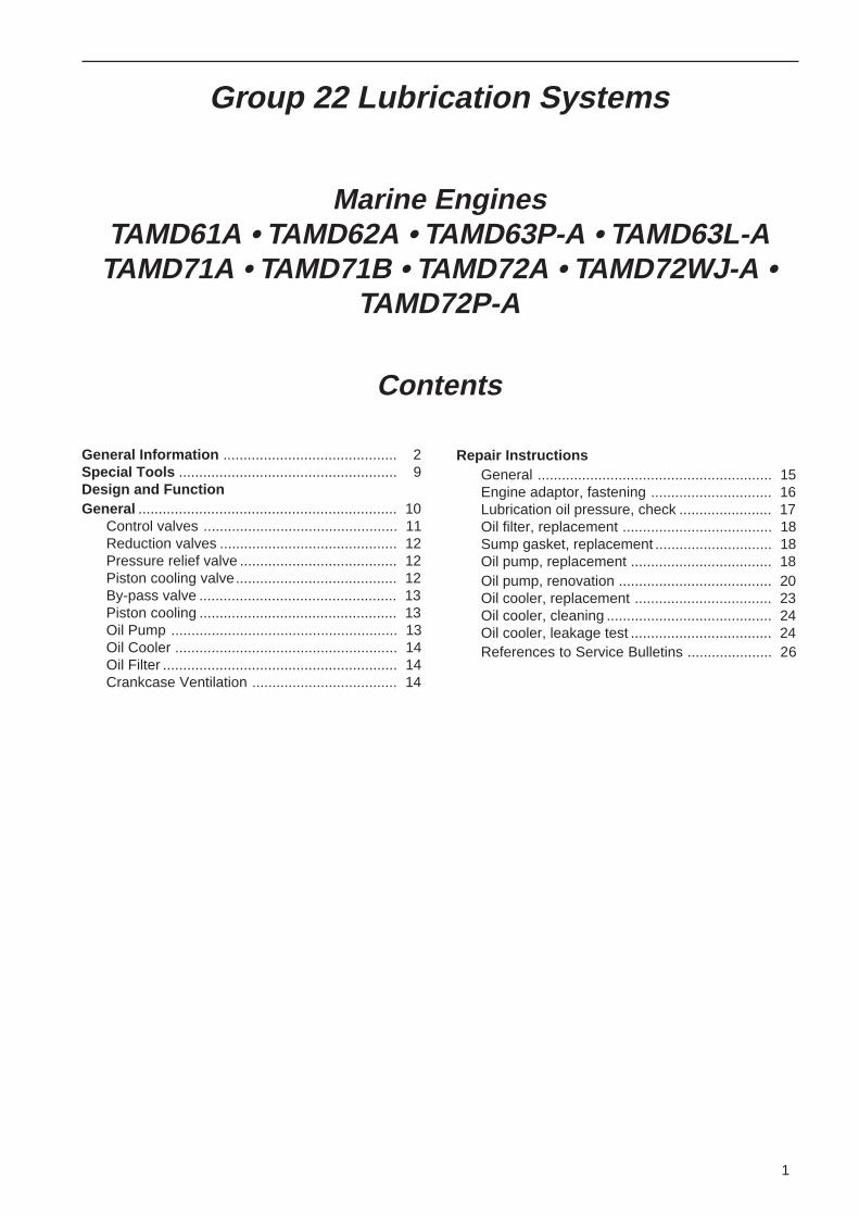
Group 22 Lubrication Systems
Marine EnginesTAMD61A • TAMD62A • TAMD63P-A • TAMD63L-ATAMD71A • TAMD71B • TAMD72A • TAMD72WJ-A •
TAMD72P-A
Contents
General Information ........................................... 2Special Tools ...................................................... 9Design and FunctionGeneral ................................................................ 10
Control valves ................................................ 11Reduction valves ............................................ 12Pressure relief valve ....................................... 12Piston cooling valve........................................ 12By-pass valve ................................................. 13Piston cooling ................................................. 13Oil Pump ........................................................ 13Oil Cooler ....................................................... 14Oil Filter .......................................................... 14Crankcase Ventilation .................................... 14
Repair InstructionsGeneral .......................................................... 15Engine adaptor, fastening .............................. 16Lubrication oil pressure, check ....................... 17Oil filter, replacement ..................................... 18Sump gasket, replacement ............................. 18Oil pump, replacement ................................... 18Oil pump, renovation ...................................... 20Oil cooler, replacement .................................. 23Oil cooler, cleaning ......................................... 24Oil cooler, leakage test ................................... 24References to Service Bulletins ..................... 26
2
Safety Precautions
IntroductionThis Workshop Manual contains technical specifica-tions, descriptions and instructions for the repair ofthe Volvo Penta products or product types describedin the Table of Contents. Check that you have thecorrect Workshop Manual for your engine.
Before starting work on the engine read the“Safety Precautions”, “General Information” and“Repair Instruction” sections of this WorkshopManual carefully.
ImportantIn this book and on the product you will find the fol-lowing special warning symbols.
WARNING! Possible danger of personal injury,extensive damage to property or serious me-chanical malfunction if the instructions are notfollowed.
IMPORTANT! Used to draw your attention tosomething that can cause damage or malfunc-tions on a product or damage to property.
Note! Used to draw your attention to important infor-mation that will facilitate the work or operation inprogress.
Below is a summary of the risks involved and safetyprecautions you should always observe or carry outwhen operating or servicing the engine.
Immobilize the engine by turning off the powersupply to the engine at the main switch (switch-es) and lock it (them) in the OFF position be-fore starting work. Set up a warning notice atthe engine control point or helm.
As a general rule all service operations mustbe carried out with the engine stopped. Howev-er, some work, for example certain adjustmentsrequire that the engine is running when theyare carried out. Approaching an engine whichis operating is a safety risk. Loose clothing orlong hair can fasten in rotating parts and causeserious personal injury. If working in proximityof an engine which is operating, carelessmovements or a dropped tool can result in per-sonal injury. Take care to avoid contact withhot surfaces (exhaust pipes, Turbocharger
(TC), air intake pipe, start element etc.) and hotliquids in lines and hoses on an engine which isrunning or which has just been stopped. Rein-stall all protective parts removed during serviceoperations before starting the engine.
Check that the warning or information labels onthe product are always clearly visible. Replacelabels which have been damaged or paintedover.
Engines with turbocharger (TC): Never start theengine without installing the air cleaner (ACL)filter. The rotating compressor in the Turbo cancause serious personal injury. Foreign objectsentering the intake ducts can also cause me-chanical damage.
Never use start spray products or similar whenstarting the engine. They may cause an explo-sion in the inlet manifold. Danger of personalinjury.
Avoid opening the filler cap for engine coolantsystem (freshwater cooled engines) when theengine is still hot. Steam or hot coolant canspray out. Open the filler cap slowly and re-lease the pressure in the system. Take greatcare if a cock, plug or engine coolant line mustbe removed from a hot engine. Steam or hotcoolant can spray out in any direction.
Hot oil can cause burns. Avoid getting hot oilon the skin. Ensure that the lubrication systemis not under pressure before carrying out anywork. Never start or operate the engine withthe oil filler cap removed, otherwise oil could beejected.
Stop the engine and close the sea cock beforecarrying out operations on the engine coolingsystem.
Only start the engine in a well-ventilated area.If operating the engine in an enclosed area en-sure that there is exhaust ventilation leadingout of the engine compartment or workshoparea to remove exhaust gases and crankcaseventilation emissions.
3
General Information
Always use protective glasses or goggles whencarrying out work where there is a risk of splin-ters, grinding sparks, acid splashes or whereother chemicals are used. The eyes are ex-tremely sensitive, an injury could result in blind-ness!
Avoid getting oil on the skin! Repeated expo-sure to oil or exposure over a long period canresult in the skin becoming dry. Irritation, dry-ness and eczema and other skin problems canthen occur. Used oil is more dangerous thanfresh oil from a health aspect. Use protectivegloves and avoid oil soaked clothes and shoprags. Wash regularly, especially before eating.There are special skin creams which counter-act drying out of the skin and make it easier toclean off dirt after work is completed.
Many chemicals used on the product (for ex-ample engine and transmission oils, glycol,gasoline and diesel oil), or chemicals used inthe workshop (for example degreasing agents,paint and solvents) are dangerous to health.Read the instructions on the product packagingcarefully! Always follow the safety precautionsfor the product (for example use of protectivemask, glasses, gloves etc.). Make sure thatother personnel are not exposed to hazardouschemicals, for example in the air. Ensure goodventilation in the work place. Follow the instruc-tions provided when disposing of used or lefto-ver chemicals.
Excercise extreme care when leak detecting onthe fuel system and testing the fuel injector jets.Use eye protection. The jet from a fuel injectornozzle is under extremely high pressure andhas great penetrative energy, so the fuel canpenetrate deep into the body tissue and causeserious personal injury. Danger of blood poi-soning.
All fuels and many chemical substances areflammable. Do not allow naked flame or sparksin the vicinity. Fuel, certain thinner productsand hydrogen from batteries can be extremelyflammable and explosive when mixed with air.Smoking is not to be permitted in the vicinity!Ensure that the work area is well ventilated andtake the necessary safety precautions beforestarting welding or grinding work. Always en-sure that there are fire extinguishers at handwhen work is being carried out.
Ensure that rags soaked in oil or fuel and usedfuel or oil filters are stored safely. Rags soakedin oil can spontaneously ignite under certaincircumstances. Used fuel and oil filters are en-vironmentally dangerous waste and must bedeposited at an approved site for destructiontogether with used lubricating oil, contaminatedfuel, paint remnants, solvent, degreasingagents and waste from washing parts.
Never expose a battery to naked flame or elec-trical sparks. Never smoke in proximity to thebatteries. The batteries give off hydrogen gasduring charging which when mixed with air canform an explosive gas - oxyhydrogen. This gasis easily ignited and highly volatile. Incorrectconnection of the battery can cause a singlespark which is sufficient to cause an explosionwith resulting damage. Do not shift the connec-tions when attempting to start the engine(spark risk) and do not lean over any of the bat-teries.
Always ensure that the Plus (positive) and Mi-nus (negative) battery leads are correctly in-stalled on the corresponding terminal posts onthe batteries. Incorrect installation can result inserious damage to the electrical equipment.Refer to the wiring diagrams.
Always use protective goggles when chargingand handling the batteries. Battery electrolytecontains sulfuric acid which is highly corrosive.Should the battery electrolyte come into con-tact with unprotected skin wash off immediatelyusing plenty of water and soap. If battery acidcomes in contact with the eyes, immediatelyflush with plenty of water and obtain medicalassistance at once.
Turn the engine off and turn off the power atthe main switch(es) before carrying out work onthe electrical system.
Clutch adjustments must be carried out withthe engine stopped.
4
General Information
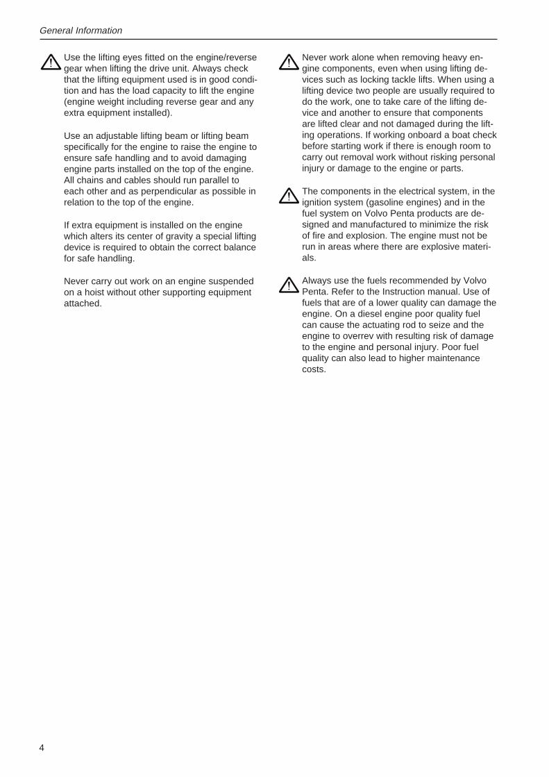
Never work alone when removing heavy en-gine components, even when using lifting de-vices such as locking tackle lifts. When using alifting device two people are usually required todo the work, one to take care of the lifting de-vice and another to ensure that componentsare lifted clear and not damaged during the lift-ing operations. If working onboard a boat checkbefore starting work if there is enough room tocarry out removal work without risking personalinjury or damage to the engine or parts.
The components in the electrical system, in theignition system (gasoline engines) and in thefuel system on Volvo Penta products are de-signed and manufactured to minimize the riskof fire and explosion. The engine must not berun in areas where there are explosive materi-als.
Always use the fuels recommended by VolvoPenta. Refer to the Instruction manual. Use offuels that are of a lower quality can damage theengine. On a diesel engine poor quality fuelcan cause the actuating rod to seize and theengine to overrev with resulting risk of damageto the engine and personal injury. Poor fuelquality can also lead to higher maintenancecosts.
Use the lifting eyes fitted on the engine/reversegear when lifting the drive unit. Always checkthat the lifting equipment used is in good condi-tion and has the load capacity to lift the engine(engine weight including reverse gear and anyextra equipment installed).
Use an adjustable lifting beam or lifting beamspecifically for the engine to raise the engine toensure safe handling and to avoid damagingengine parts installed on the top of the engine.All chains and cables should run parallel toeach other and as perpendicular as possible inrelation to the top of the engine.
If extra equipment is installed on the enginewhich alters its center of gravity a special liftingdevice is required to obtain the correct balancefor safe handling.
Never carry out work on an engine suspendedon a hoist without other supporting equipmentattached.
5
General Information
About this Workshop ManualThis Workshop Manual contains technical specifica-tions, descriptions and instructions for the repair ofthe following engines in standard format: TAMD61A,TAMD62A, TAMD63P-A, TAMD63L-A, TAMD71A,TAMD71B, TAMD72A, TAMD72WJ-A, TAMD72P-A.This Workshop Manual can show operations carriedout on any of the engines listed above. As a resultthe illustrations and pictures in the manual that showcertain parts on the engines, do not in some casesapply to all the engines listed. However the repairand service operations described are in all essentialdetails the same. Where they are not the same this isstated in the manual and where the difference is con-siderable the operations are described separately.The Engine Designations and Engine Number canbe found on the product plate. Please always includeboth the engine designation and the engine numberin all correspondance.
The Workshop Manual is produced primarily for theuse of Volvo Penta workshops and service techni-cians. For this reason the manual presupposes acertain basic knowledge of marine propulsion sys-tems and that the user can carry out the mechanical/electrical work described to a general standard of en-gineering competence.
Volvo Penta products are under a continual processof development and we therefore reserve all rightsregarding changes and modifications. All the infor-mation in this manual is based on product specifica-tions available at the time the book was published.Any essential changes or modifications introducedinto production or updated or revised service meth-ods introduced after the date of publication will beprovided in the form of Service Bulletins.
Replacement partsReplacement parts for the electrical and fuel systemsare subject to various national safety requirements,for example the United States Coast Guard SafetyRegulations. Volvo Penta Original Spare Parts meetthese specifications. Any type of damage which isthe result of using replacement parts that are notoriginal Volvo Penta replacement parts for the prod-uct in question will not be covered under any warran-ty or guarantee provided by AB Volvo Penta.
Certificated enginesEngines certificated to meet national and regionalenvironmental legislation (for example Lake Con-stance) carry with them an undertaking from themanufacturer that both new and existing engines inuse meet the enviromental demands of the legisla-tion. The product must correspond to the validatedexample that was granted certification. In order forVolvo Penta as the manufacturer to take responsibili-ty for engines in use, certain requirements regardingservice and spare parts must be met by the user ac-cording to the following:
• The Service Intervals and maintenance opera-tions recommended by Volvo Penta must be fol-lowed.
• Only Volvo Penta Original Spare Parts intendedfor the certificated engine may be used.
• Service work on the ignition system, timing andfuel injection system (gasoline) or injection pumpand injectors (diesel) must always be carried outby an authorized Volvo Penta workshop.
• The engine may not be altered or modified inany way, with the exception of accessories andservice kits developed by Volvo Penta for thatengine.
• No modifications to the exhaust pipes and airsupply ducts for the engine room (ventilationducts) may be undertaken as this may effect ex-haust emissions.
• Any seals on the engine may not be broken oth-er than by authorized persons.
IMPORTANT! If replacement parts are requireduse only Volvo Penta Original Parts. Use of re-placement parts other than AB Volvo PentaOriginal Parts will result in AB Volvo Pentabeing unable to assume any liability that theengine corresponds to the certificated en-gine variant. Volvo Penta AB excludes any lia-bility for all and any type of damage or costscaused by the use of replacement parts thatare not Volvo Penta Original Parts for the prod-uct in question.
6
Repair instructions and methods
The working methods described in the WorkshopManual apply to work carried out in a workshop. Theengine has been removed from the boat and is in-stalled in an engine fixture. Unless otherwise statedreconditioning work which can be carried out with theengine in place follows the same working method.
Warning symbols used in this Workshop Manual (forfull explanation of the symbols refer to the section;“Safety Precautions”)
WARNING!
IMPORTANT!
Note!
are not in any way comprehensive since it is impossi-ble to predict every circumstance under which ser-vice work or repairs may be carried out. Volvo PentaAB can only indicate the risks considered likely to oc-cur as a result of incorrect working methods in a well-equipped workshop using working methods and toolstested by Volvo Penta AB.
All operations described in the Workshop Manual forwhich there are Volvo Penta Special Tools availableassume that these tools are used by the servicetechnician or person carrying out the repair. VolvoPenta Special Tools have been specifically devel-oped to ensure as safe and rational working methodsas possible. It is therefore the responsibility of theperson or persons using other than Volvo Penta Spe-cial Tools or approved Volvo Penta working methods(as described in a Workshop Manual or Service Bul-letin), to acquaint themselves of the risk of personalinjury or actual mechanical damage or malfunctionthat can result from failing to use the prescribed toolsor working method.
In some cases special safety precautions and userinstructions may be required in order to use the toolsand chemicals mentioned in the Workshop Manual.Always follow these precautions as there are no spe-cific instructions given in the Workshop Manual.
By following these basic recommendations and usingcommon sense it is possible to avoid most of therisks involved in the work. A clean work place and aclean engine will eliminate many risks of personal in-jury and engine malfunction.
Above all when working on the fuel system, enginelubrication system, air intake system, Turbochargerunit, bearing seals and seals it is extremely importantto observe the highest standards of cleanliness andavoid dirt or foreign objects entering the parts or sys-tems, since this can result in reduced service life ormalfunctions.
Our joint responsibilityEvery engine consists of many systems and compo-nents that work together. If one component deviatesfrom the technical specifications this can have dra-matic consequences on the environmental impact ofthe engine even if it is otherwise in good running or-der. It is therefore critical that the stated wear toler-ances are observed, that systems which can be ad-justed are correctly set up and that only Volvo PentaOriginal Parts are used on the engine. The statedservice intervals in the Maintenance Schedule mustbe followed.Some systems, such as the components in the fuelsystem, require special expertise and special testingequipment for service and maintenance. Some com-ponents are factory sealed for environmental andproduct specific reasons. Under no circumstancesattempt to service or repair a sealed component un-less the service technician carrying out the work isauthorized to do so.Bear in mind that most of the chemicals used aroundboats are harmful to the environment if used incor-rectly. Volvo Penta recommends the use of bio-de-gradable degreasing agents for all cleaning of enginecomponents unless otherwise stated in the Work-shop Manual. When working onboard a boat make aspecial point of preventing oil, waste water fromwashing components entering the bilges; instead re-move all such waste for safe disposal at an approvedsite for destruction.
Tightening torquesThe correct tightening torques for critical joints whichmust be tightened using a torque wrench are listedunder “Technical Specifications -Tightening Torques”and stated in the method descriptions in the Work-shop Manual. All tightening torques apply to cleanedthreads, bolt heads and mating surfaces. Tigtheningtorques stated are for lightly oiled or dry threads.Where grease, locking or sealing agents are requiredfor screwed joints this is stated in both the operationdescription and in ”Tightening Torques”. Where notightening torque is stated for a joint use the generaltightening torques according to the tables below. Thetightening torques stated are a guide and the jointdoes not have to be tightened using a torque wrench.
Dimension Tightening torqueNm ft.lbs
M5 6 4,4M6 10 7,4M8 25 18,4M10 50 36,9M12 80 59,0M14 140 103,3
7
General Information
Tightening torque withProtractor tightening(angle tightening)Tightening using both a torque setting and a protrac-tor angle requires that first the recommended torqueis applied using a torque wrench and then the recom-mended angle is added according to the protractorscale. Example: a 90° protractor tightening meansthat the joint is tightened a further 1/4 turn in one op-eration after the stated tightening torque has beenapplied.
Lock nutsDo not re-use lock nuts that have been removed dur-ing dissassembly operations as these have reducedservice life when re-used - use new nuts when as-sembling or reinstalling. For lock nuts with a plasticinsert such as Nylock® the tightening torque statedin the table is reduced if the Nylock® nut has thesame head height as a standard hexagonal nut with-out plastic insert. Reduce the tightening torque by25% for bolt size 8 mm or larger. Where Nylock®nuts are higher, or of the same height as a standardhexagonal nut, the tightening torques given in the ta-ble apply.
Strength classesBolts and nuts are divided up into different classes ofstrength; the class is indicated by the number on thebolt head. A high number indicates stronger material,for example a bolt marked 10–9 indicates a higherstrength than one marked 8–8. It is therefore impor-tant that bolts removed during the disassembly of abolted joint must be reinstalled in their original posi-tion when assembling the joint. If a bolt must be re-placed check in the replacement parts catalogue tomake sure the correct bolt is used.
SealantA number of sealants and locking liquids are used onthe engines. The agents have varying properties andare used for different types of jointing strengths, op-erating temperature ranges, resistance to oil and oth-er chemicals and for the different materials and gapsizes in the engines.
To ensure service work is correctly carried out it isimportant that the correct sealant and locking fluidtype is used on the joint where the agents are re-quired.
In this Volvo Penta Workshop Manual the user willfind that each section where these agents are ap-plied in production states which type was used onthe engine.
During service operations use the same agent or analternative from a different manufacturer.
Make sure that mating surfaces are dry and free fromoil, grease, paint and anti-corrosion agent before ap-plying sealant or locking fluid. Always follow the man-ufacturer’s instructions for use regarding temperaturerange, curing time and any other instructions for theproduct.
Two different basic types of agent are used on theengine and these are:
RTV agent (Room temperature vulcanizing). Usedfor gaskets, sealing gasket joints or coating gaskets.RTV is visible when a part has been disassembled;old RTV must be removed before resealing the joint.
The following RTV agents are mentioned in the Ser-vice Manual: Loctite® 574, Volvo Penta P/N 840879-1, Permatex® No. 3, Volvo Penta P/N 1161099-5,Permatex® Nr 77. Old sealant can be removed usingmethylated spirits in all cases.
Anaerobic agents. These agents cure in an absenceof air. They are used when two solid parts, for exam-ple cast components, are installed face-to-face with-out a gasket. They are also commonly used to se-cure plugs, threads in stud bolts, cocks, oil pressureswitches and so on. The cured material is glass-likeand it is therefore colored to make it visible. Curedanaerobic agents are extremely resistant to solventsand the old agent cannot be removed. When rein-stalling the part is carefully degreased and then newsealant is applied.
The following anaerobic agents are mentioned in theWorkshop Manual: Loctite® 572 (white), Loctite®241 (blue).
Note : Loctite® is the registered trademark of Loctite Corparation,Permatex® the registered trademark of the Permatex Corporation.
8
General Information
Safety rules for fluorocarbonrubberFluorocarbon rubber is a common material in sealrings for shafts, and in O-rings, for example.
When fluorocarbon rubber is subjected to high tem-peratures (above 300°C), hydrofluoric acid can beformed, which is highly corrosive. Skin contact cangive severe chemical burns. Splashes in your eyescan give severe chemical burns. If you breathe in thefumes, your lungs can be permanently damaged.
Warning! Be very careful when working on en-gines which have been exposed to high tem-peratures, e.g. overheating during a seizure orfire. Seals must never be cut with an oxy-acety-lene torch, or be burned up afterwards in an un-controlled manner.
• Always use gloves made of chloroprene rubber(gloves for handling chemicals) and protectivegoggles.
• Handle the removed seal in the same way ascorrosive acid. All residue, including ash, can behighly corrosive. Never use compressed air toblow anything clean.
• Put the remains in a plastic box which is sealedand provided with a warning label. Wash thegloves under running water before removingthem.
The following seals are probably made from fluoro-carbon rubber:
Seal rings for the crankshaft, camshaft, intermediateshafts.
O-rings irrespective of where they are installed. O-rings for cylinder liner sealing are almost alwaysmade from fluorocarbon rubber.
Note that seals which have not been subjected tohigh temperature can be handled normally.
9
Special tools
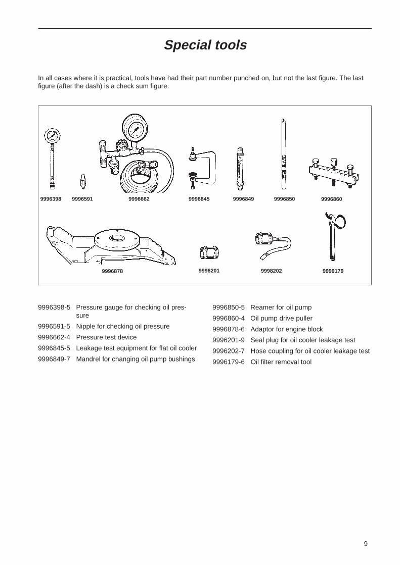
In all cases where it is practical, tools have had their part number punched on, but not the last figure. The lastfigure (after the dash) is a check sum figure.
9996398-5 Pressure gauge for checking oil pres-sure
9996591-5 Nipple for checking oil pressure
9996662-4 Pressure test device
9996845-5 Leakage test equipment for flat oil cooler
9996849-7 Mandrel for changing oil pump bushings
9996850-5 Reamer for oil pump
9996860-4 Oil pump drive puller
9996878-6 Adaptor for engine block
9996201-9 Seal plug for oil cooler leakage test
9996202-7 Hose coupling for oil cooler leakage test
9996179-6 Oil filter removal tool
9996398 9996591 9996662 9996845 9996849 9996850 9996860
9998201 9998202 99991799996878
10
Design and Function
GeneralThe engines have a pressurised lubrication systemcontaining a full flow oil filter, an oil cooler and pistoncooling.
The TAMD 63 also has a by-pass oil filter for the lub-rication oil. (The by-pass oil filter is an optional extrafor the other engines.)
The oil pump is located at the front of the sump, andis driven by the crankshaft, via an idler wheel. Thepump sucks up oil from the sump and forces it outinto two oil galleries in the cylinder block, via the oilfilter, to the lubrication points in the engine, via thepiston cooling valve and the oil cooler to the pistoncooling nozzles.
All bearings, the gudgeon pins and the bearings ofthe valve mechanism and gear wheel drives are con-nected to the pressure lubrication system. The injec-tion pump and turbocharger are also connected tothe pressure lubrication system.
The gear wheel drives are lubricated by splash fromthe idler wheel bearing, which is connected to themain oil gallery by drillings.
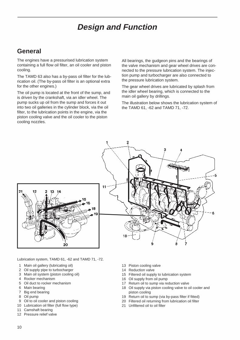
The illustration below shows the lubrication system ofthe TAMD 61, -62 and TAMD 71, -72.
Lubrication system, TAMD 61, -62 and TAMD 71, -72.
1 Main oil gallery (lubricating oil)2 Oil supply pipe to turbocharger3 Main oil system (piston cooling oil)4 Rocker mechanism5 Oil duct to rocker mechanism6 Main bearing7 Big end bearing8 Oil pump9 Oil to oil cooler and piston cooling
10 Lubrication oil filter (full flow type)11 Camshaft bearing12 Pressure relief valve
13 Piston cooling valve14 Reduction valve15 Filtered oil supply to lubrication system16 Oil supply from oil pump17 Return oil to sump via reduction valve18 Oil supply via piston cooling valve to oil cooler and
piston cooling19 Return oil to sump (via by-pass filter if fitted)20 Filtered oil returning from lubrication oil filter21 Unfiltered oil to oil filter
11
Design and Function
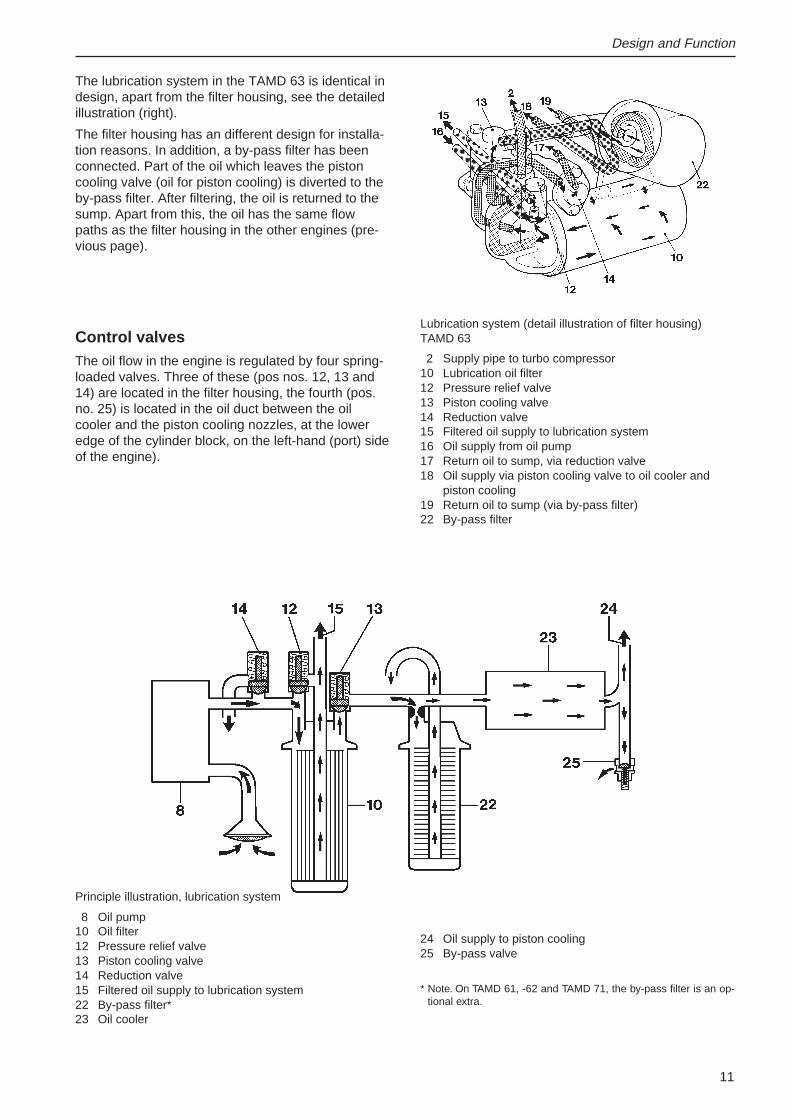
The lubrication system in the TAMD 63 is identical indesign, apart from the filter housing, see the detailedillustration (right).
The filter housing has an different design for installa-tion reasons. In addition, a by-pass filter has beenconnected. Part of the oil which leaves the pistoncooling valve (oil for piston cooling) is diverted to theby-pass filter. After filtering, the oil is returned to thesump. Apart from this, the oil has the same flowpaths as the filter housing in the other engines (pre-vious page).
Principle illustration, lubrication system
8 Oil pump10 Oil filter12 Pressure relief valve13 Piston cooling valve14 Reduction valve15 Filtered oil supply to lubrication system22 By-pass filter*23 Oil cooler
24 Oil supply to piston cooling25 By-pass valve
* Note. On TAMD 61, -62 and TAMD 71, the by-pass filter is an op-tional extra.
Lubrication system (detail illustration of filter housing)TAMD 63
2 Supply pipe to turbo compressor10 Lubrication oil filter12 Pressure relief valve13 Piston cooling valve14 Reduction valve15 Filtered oil supply to lubrication system16 Oil supply from oil pump17 Return oil to sump, via reduction valve18 Oil supply via piston cooling valve to oil cooler and
piston cooling19 Return oil to sump (via by-pass filter)22 By-pass filter
Control valvesThe oil flow in the engine is regulated by four spring-loaded valves. Three of these (pos nos. 12, 13 and14) are located in the filter housing, the fourth (pos.no. 25) is located in the oil duct between the oilcooler and the piston cooling nozzles, at the loweredge of the cylinder block, on the left-hand (port) sideof the engine).
12
Design and Function
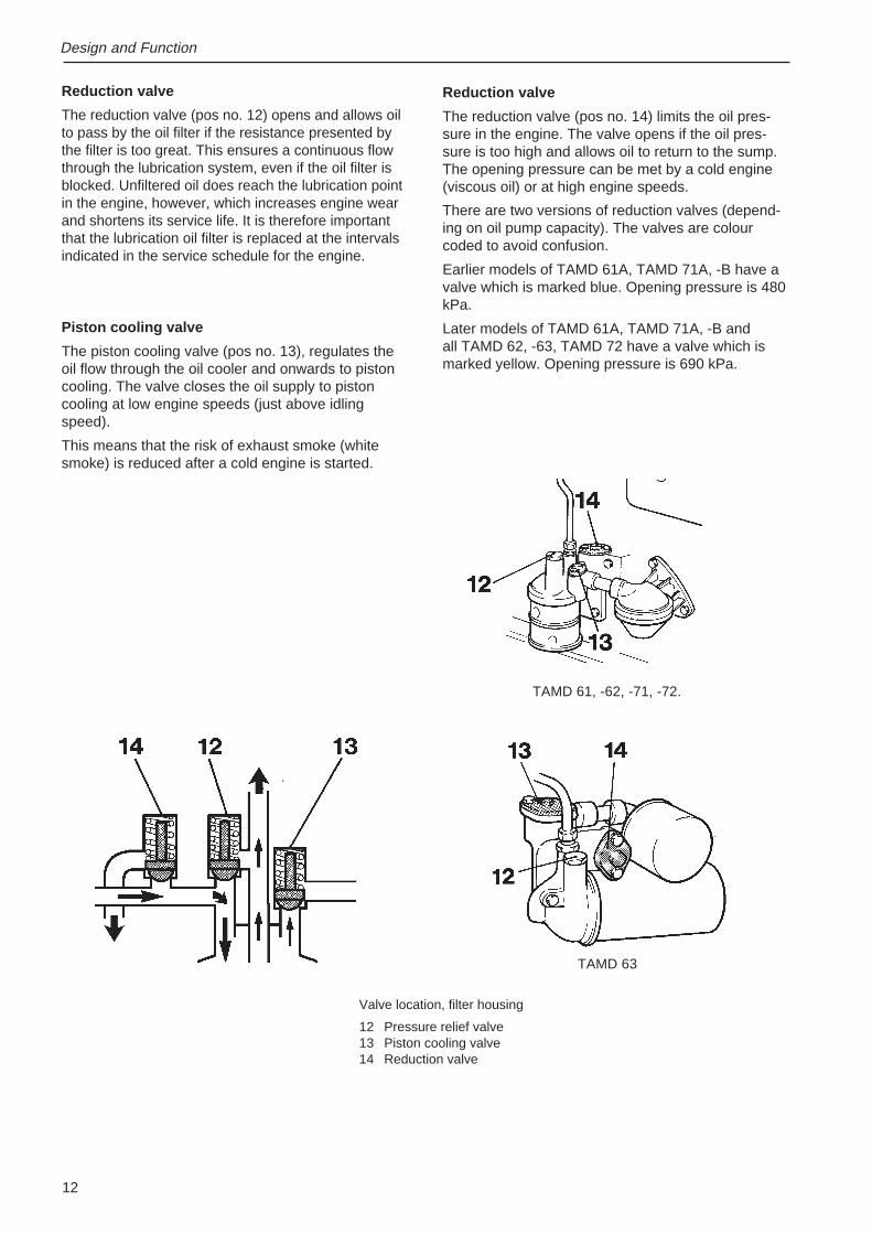
Reduction valve
The reduction valve (pos no. 12) opens and allows oilto pass by the oil filter if the resistance presented bythe filter is too great. This ensures a continuous flowthrough the lubrication system, even if the oil filter isblocked. Unfiltered oil does reach the lubrication pointin the engine, however, which increases engine wearand shortens its service life. It is therefore importantthat the lubrication oil filter is replaced at the intervalsindicated in the service schedule for the engine.
Piston cooling valve
The piston cooling valve (pos no. 13), regulates theoil flow through the oil cooler and onwards to pistoncooling. The valve closes the oil supply to pistoncooling at low engine speeds (just above idlingspeed).
This means that the risk of exhaust smoke (whitesmoke) is reduced after a cold engine is started.
Reduction valve
The reduction valve (pos no. 14) limits the oil pres-sure in the engine. The valve opens if the oil pres-sure is too high and allows oil to return to the sump.The opening pressure can be met by a cold engine(viscous oil) or at high engine speeds.
There are two versions of reduction valves (depend-ing on oil pump capacity). The valves are colourcoded to avoid confusion.
Earlier models of TAMD 61A, TAMD 71A, -B have avalve which is marked blue. Opening pressure is 480kPa.
Later models of TAMD 61A, TAMD 71A, -B andall TAMD 62, -63, TAMD 72 have a valve which ismarked yellow. Opening pressure is 690 kPa.
Valve location, filter housing
12 Pressure relief valve13 Piston cooling valve14 Reduction valve
TAMD 63
TAMD 61, -62, -71, -72.
13
Design and Function
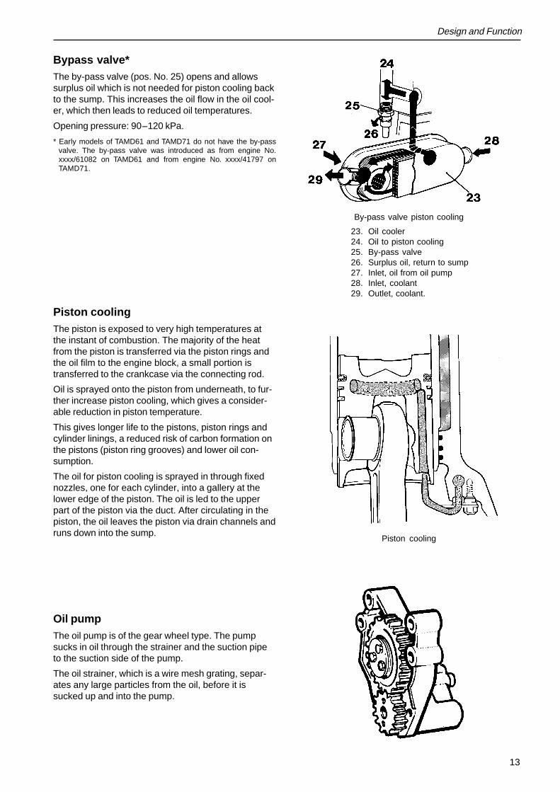
Bypass valve*The by-pass valve (pos. No. 25) opens and allowssurplus oil which is not needed for piston cooling backto the sump. This increases the oil flow in the oil cool-er, which then leads to reduced oil temperatures.
Opening pressure: 90–120 kPa.
* Early models of TAMD61 and TAMD71 do not have the by-passvalve. The by-pass valve was introduced as from engine No.xxxx/61082 on TAMD61 and from engine No. xxxx/41797 onTAMD71.
Piston coolingThe piston is exposed to very high temperatures atthe instant of combustion. The majority of the heatfrom the piston is transferred via the piston rings andthe oil film to the engine block, a small portion istransferred to the crankcase via the connecting rod.
Oil is sprayed onto the piston from underneath, to fur-ther increase piston cooling, which gives a consider-able reduction in piston temperature.
This gives longer life to the pistons, piston rings andcylinder linings, a reduced risk of carbon formation onthe pistons (piston ring grooves) and lower oil con-sumption.
The oil for piston cooling is sprayed in through fixednozzles, one for each cylinder, into a gallery at thelower edge of the piston. The oil is led to the upperpart of the piston via the duct. After circulating in thepiston, the oil leaves the piston via drain channels andruns down into the sump.
Oil pumpThe oil pump is of the gear wheel type. The pumpsucks in oil through the strainer and the suction pipeto the suction side of the pump.
The oil strainer, which is a wire mesh grating, separ-ates any large particles from the oil, before it issucked up and into the pump.
By-pass valve piston cooling
23. Oil cooler24. Oil to piston cooling25. By-pass valve26. Surplus oil, return to sump27. Inlet, oil from oil pump28. Inlet, coolant29. Outlet, coolant.
Piston cooling
14
Design and Function
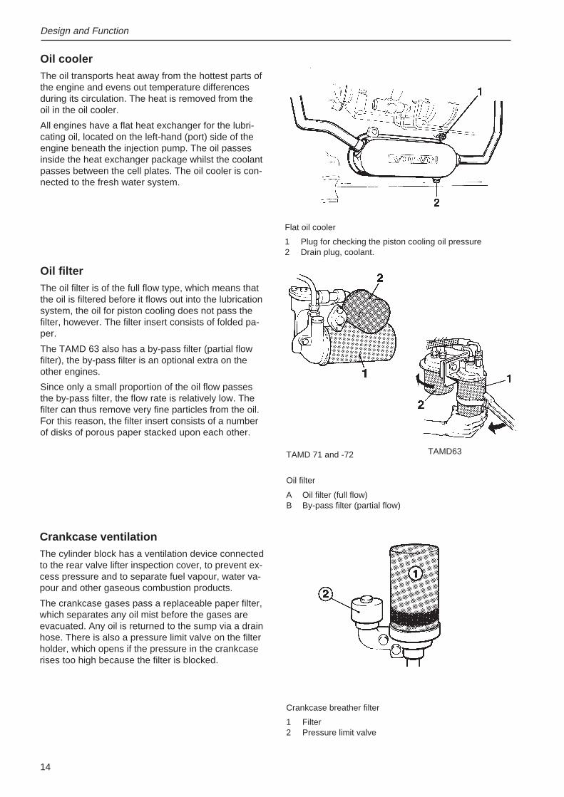
Oil coolerThe oil transports heat away from the hottest parts ofthe engine and evens out temperature differencesduring its circulation. The heat is removed from theoil in the oil cooler.
All engines have a flat heat exchanger for the lubri-cating oil, located on the left-hand (port) side of theengine beneath the injection pump. The oil passesinside the heat exchanger package whilst the coolantpasses between the cell plates. The oil cooler is con-nected to the fresh water system.
TAMD63TAMD 71 and -72
Oil filter
A Oil filter (full flow)B By-pass filter (partial flow)
Crankcase breather filter
1 Filter2 Pressure limit valve
Flat oil cooler
1 Plug for checking the piston cooling oil pressure2 Drain plug, coolant.
Oil filterThe oil filter is of the full flow type, which means thatthe oil is filtered before it flows out into the lubricationsystem, the oil for piston cooling does not pass thefilter, however. The filter insert consists of folded pa-per.
The TAMD 63 also has a by-pass filter (partial flowfilter), the by-pass filter is an optional extra on theother engines.
Since only a small proportion of the oil flow passesthe by-pass filter, the flow rate is relatively low. Thefilter can thus remove very fine particles from the oil.For this reason, the filter insert consists of a numberof disks of porous paper stacked upon each other.
Crankcase ventilationThe cylinder block has a ventilation device connectedto the rear valve lifter inspection cover, to prevent ex-cess pressure and to separate fuel vapour, water va-pour and other gaseous combustion products.
The crankcase gases pass a replaceable paper filter,which separates any oil mist before the gases areevacuated. Any oil is returned to the sump via a drainhose. There is also a pressure limit valve on the filterholder, which opens if the pressure in the crankcaserises too high because the filter is blocked.
15
Measures before lifting the engine out ofthe boat5 Turn the battery isolator off. Undo the battery
connections to the start motor.
6 Undo the connectors between the engine cables– instruments.
7 Undo the sea water connections/keel coolingconnections.
8 Undo the exhaust pipe.
9 Shut the fuel cocks. Undo the fuel connections.
10 Undo the throttle and gear selector cables.
11 Undo the propeller shaft from the reversing gear.Undo the engine mounting pads from the enginebed and lift the engine out.
Measures after lifting the engine out12 Clean the engine
Warning! Observe the following instruction ifyou are going to clean the engine with a highpressure washer. Be very careful when clean-ing, to avoid water entry into the engine. Whenthe high pressure function is engaged, thewater jet must never be aimed at seals, e.g.shaft seals, joints with gaskets, rubber hoses orelectrical components.
13 Drain the engine oil off.
14 Remove the reversing gear (when necessary)
Repair Instructions
GeneralA condition test should be done before each majorservice job, if possible, to ascertain the general con-dition of the engine, and any combined fault sourcescan be discovered. It is necessary that the enginecan be run to do the condition test, so this should bedone before the engine or engine components aredisassembled.
Please refer to the workshop manual, Engine block,for information about the condition test.
Measures before renovation in the boat1 Turn the battery isolator off.
2 Clean the outside of the engine.
NOTE! Make sure that the residue formed bywashing is collected and sent for destruction,and does not inadvertently end up in the country-side. Please refer to the warning text in item 11as well.
3 Tasks involving work on the cooling system.Shut the sea cock and drain the coolant from thesea water and fresh water systems.
Work involving cooling systems with keel cool-ing: Shut the cocks leading to the keel coolerand drain the coolant from the engine.
Warning! Make sure that all sea water inletsare securely closed and that water entry cannot take place when the cooling system compo-nents are disassembled.
16
Repair Instructions
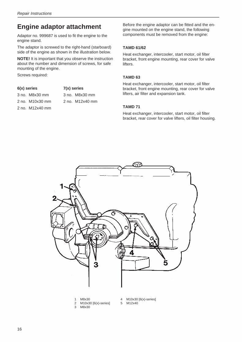
Engine adaptor attachmentAdaptor no. 999687 is used to fit the engine to theengine stand.
The adaptor is screwed to the right-hand (starboard)side of the engine as shown in the illustration below.
NOTE! It is important that you observe the instructionabout the number and dimension of screws, for safemounting of the engine.
Screws required:
6(x) series 7(x) series
3 no. M8x30 mm 3 no. M8x30 mm
2 no. M10x30 mm 2 no. M12x40 mm
2 no. M12x40 mm
Before the engine adaptor can be fitted and the en-gine mounted on the engine stand, the followingcomponents must be removed from the engine:
TAMD 61/62
Heat exchanger, intercooler, start motor, oil filterbracket, front engine mounting, rear cover for valvelifters.
TAMD 63
Heat exchanger, intercooler, start motor, oil filterbracket, front engine mounting, rear cover for valvelifters, air filter and expansion tank.
TAMD 71
Heat exchanger, intercooler, start motor, oil filterbracket, rear cover for valve lifters, oil filter housing.
1 M8x30 4 M10x30 [6(x)-series]2 M10x30 [6(x)-series] 5 M12x403 M8x30
17
• Faulty oil grade (viscosity)
If the oil is too thick (incorrect viscosity or the oilis contaminated with too many soot particles),the oil pressure takes too long to rise after astart, especially in cold weather.
If the oil shows abnormal amounts of soot, althoughthe oil is changed at the recommended intervals, andthe correct grade has been used, the reason for thefault could also be:
– incorrect combustion because of incorrect fuelgrade.
– incorrectly set injectors
– incorrect injection advance
– engine worn outside permitted wear limits (oilleakage past piston rings, valve guides etc.)
The oil has become too thin (has the wrong viscosity)because of dilution with fuel.
This can be caused by incorrect combustion becauseof
– incorrectly set injectors
– incorrect injection advance
The fault is most easily noticed because of low oilconsumption. The low oil consumption is an illusion,since the burned oil is compensated by dilution withunburned fuel, so that the oil level can remain con-stant.
• Oil filters blocked
When the oil filter is blocked, the filter by-passvalve is opened, which allows the normal oil flowresistance through the filters to fall. This is no-ticeable by a fall in pressure on idling with a hotengine.
• Defective reduction valve
• Defective piston cooling valve
• Defective oil pump
Worn or leaky oil pump.
Repair Instructions
Oil pressure, checkSpecial tools: 9996398, 9996591
1
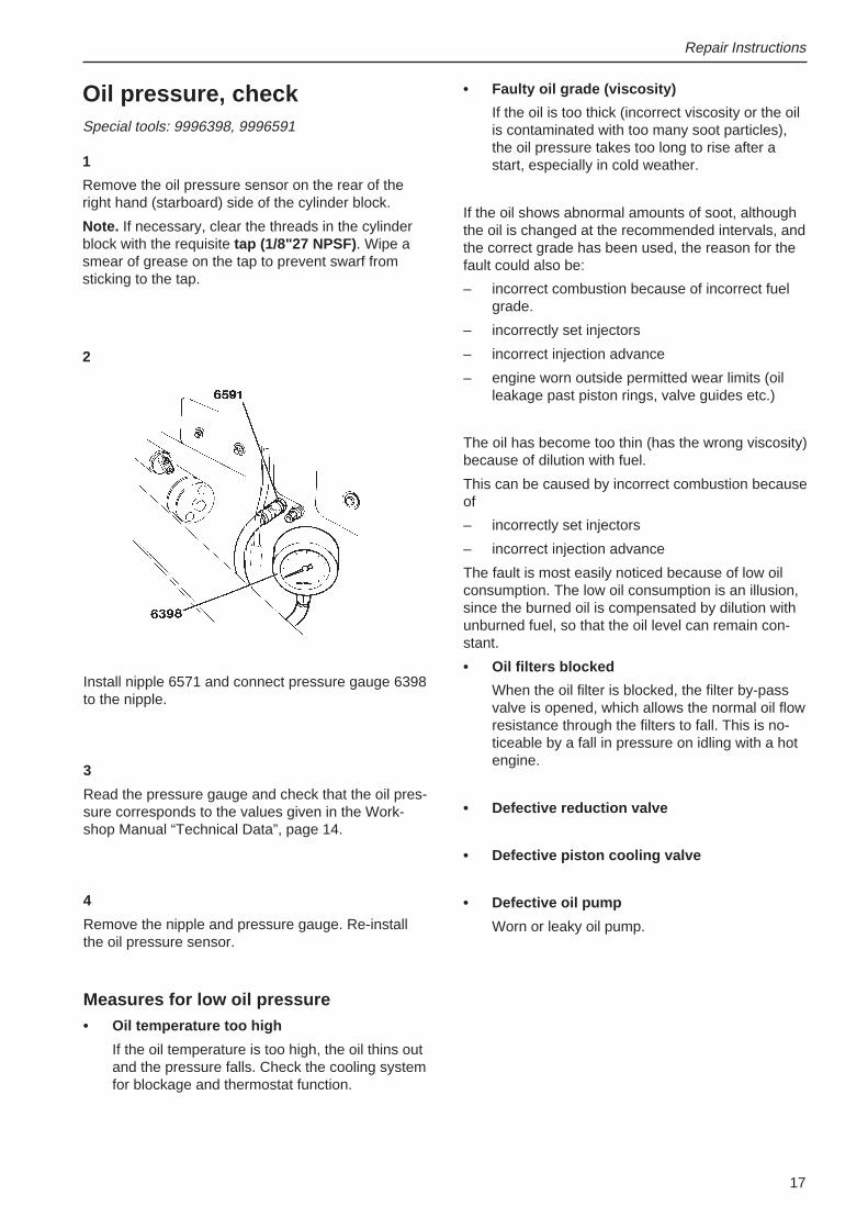
Remove the oil pressure sensor on the rear of theright hand (starboard) side of the cylinder block.
Note. If necessary, clear the threads in the cylinderblock with the requisite tap (1/8"27 NPSF) . Wipe asmear of grease on the tap to prevent swarf fromsticking to the tap.
2
Install nipple 6571 and connect pressure gauge 6398to the nipple.
3
Read the pressure gauge and check that the oil pres-sure corresponds to the values given in the Work-shop Manual “Technical Data”, page 14.
4
Remove the nipple and pressure gauge. Re-installthe oil pressure sensor.
Measures for low oil pressure• Oil temperature too high
If the oil temperature is too high, the oil thins outand the pressure falls. Check the cooling systemfor blockage and thermostat function.
18
Repair Instructions
Oil filter, replacementSpecial tool: 9999179
1
Put a collection vessel beneath the filters or pull aplastic bag over the filters.
2
Clean the filter bracket and undo the filters with toolno. 9179.
3
Moisten the gaskets of the new filters with oil, andscrew them on by hand until the gasket comes intocontact with the filter bracket. Then turn a further3/4 turn.
4
Top up with engine oil and run the engine on the startmotor until the oil pressure gauge gives a reading.
Note. The engine should be turned with the startmotor when the filter, oil cooler or other componentsin the lubrication system are changed.
5
Start the engine and check for leakage past the oilfilters.
Oil pump, replacement
(Sump removed)
Removal
1
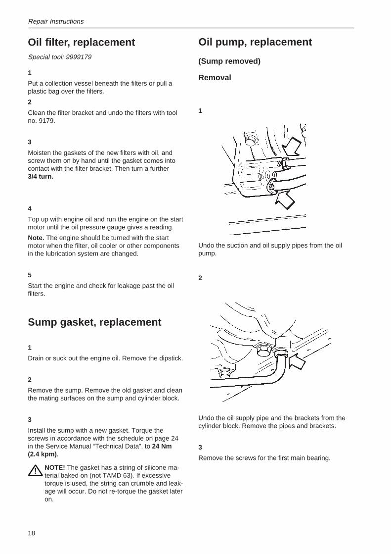
Undo the oil supply pipe and the brackets from thecylinder block. Remove the pipes and brackets.
3
Remove the screws for the first main bearing.
2
Sump gasket, replacement
1
Drain or suck out the engine oil. Remove the dipstick.
2
Remove the sump. Remove the old gasket and cleanthe mating surfaces on the sump and cylinder block.
3
Install the sump with a new gasket. Torque thescrews in accordance with the schedule on page 24in the Service Manual “Technical Data”, to 24 Nm(2.4 kpm) .
NOTE! The gasket has a string of silicone ma-terial baked on (not TAMD 63). If excessivetorque is used, the string can crumble and leak-age will occur. Do not re-torque the gasket lateron.
Undo the suction and oil supply pipes from the oilpump.
19
Install the oil supply pipe on the pump and the cylin-der block.
Tighten the unions by hand.
Note! If you re-install the old supply pipe, check theends of the pipe for cracks.
10
Tighten the unions on the pump and the cylinderblock until they bottom.
11
Mark the unions with a felt-tip pen.
Note! Permanent marking must not be used.
5
Repair Instructions
4
Remove the oil pump, together with the main bear-ing.
Remove the bearing shell from the cap.
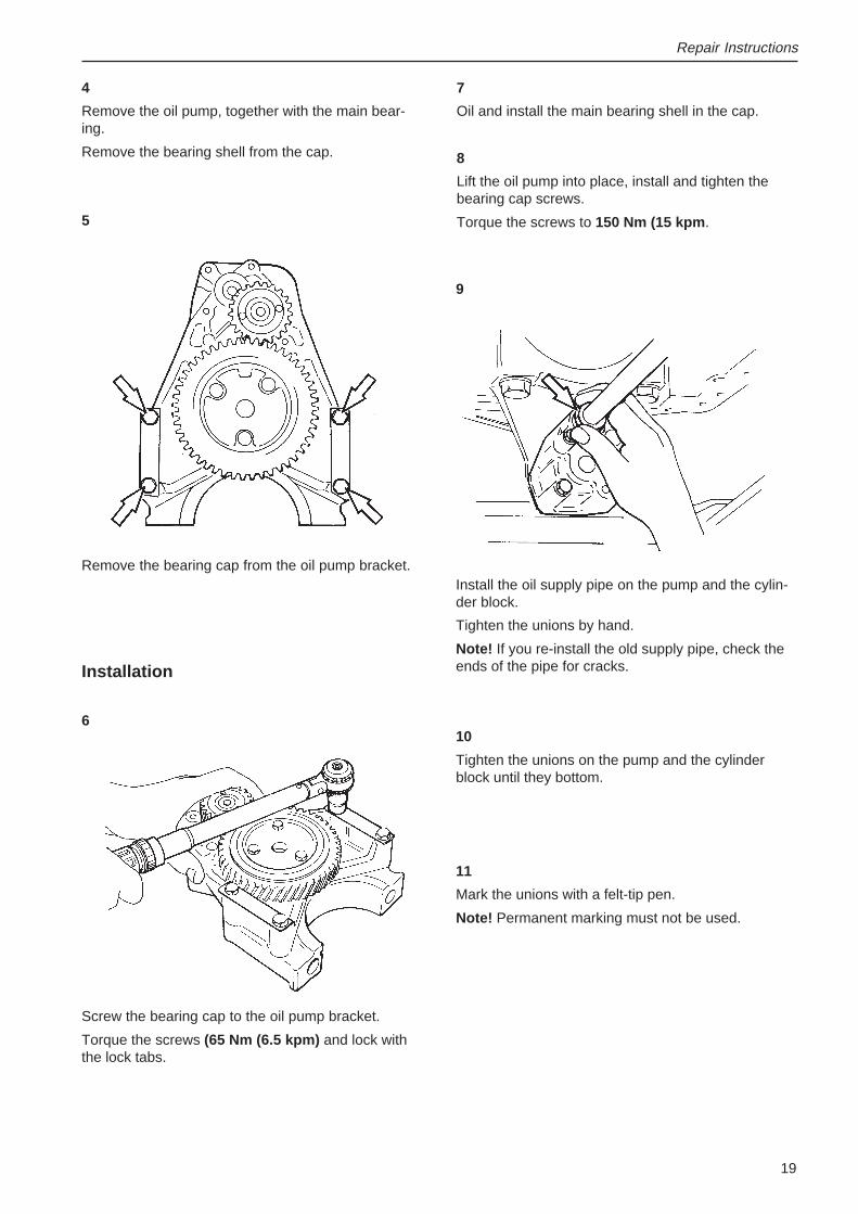
Remove the bearing cap from the oil pump bracket.
7
Oil and install the main bearing shell in the cap.
8
Lift the oil pump into place, install and tighten thebearing cap screws.
Torque the screws to 150 Nm (15 kpm .
9
Installation
6
Screw the bearing cap to the oil pump bracket.
Torque the screws (65 Nm (6.5 kpm) and lock withthe lock tabs.
20
Repair Instructions
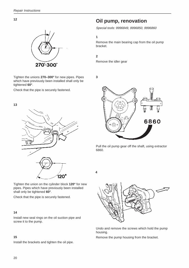
12
Tighten the unions 270–300° for new pipes. Pipeswhich have previously been installed shall only betightened 60°.
Check that the pipe is securely fastened.
Oil pump, renovationSpecial tools: 9996849, 9996850, 9996860
1
Remove the main bearing cap from the oil pumpbracket.
2
Remove the idler gear
3
Pull the oil pump gear off the shaft, using extractor6860.
Undo and remove the screws which hold the pumphousing.
Remove the pump housing from the bracket.
13
Tighten the union on the cylinder block 120° for newpipes. Pipes which have previously been installedshall only be tightened 60°.
Check that the pipe is securely fastened.
14
Install new seal rings on the oil suction pipe andscrew it to the pump.
15
Install the brackets and tighten the oil pipe.
4
21
Repair Instructions
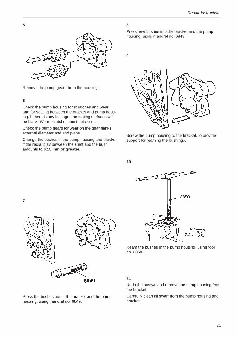
5
Remove the pump gears from the housing
6
Check the pump housing for scratches and wear,and for sealing between the bracket and pump hous-ing. If there is any leakage, the mating surfaces willbe black. Wear scratches must not occur.
Check the pump gears for wear on the gear flanks,external diameter and end plane.
Change the bushes in the pump housing and bracketif the radial play between the shaft and the bushamounts to 0.15 mm or greater.
8
Press new bushes into the bracket and the pumphousing, using mandrel no. 6849.
9
Press the bushes out of the bracket and the pumphousing, using mandrel no. 6849.
Screw the pump housing to the bracket, to providesupport for reaming the bushings.
Ream the bushes in the pump housing, using toolno. 6850.
11
Undo the screws and remove the pump housing fromthe bracket.
Carefully clean all swarf from the pump housing andbracket.
7
10
22
Repair Instructions
1512
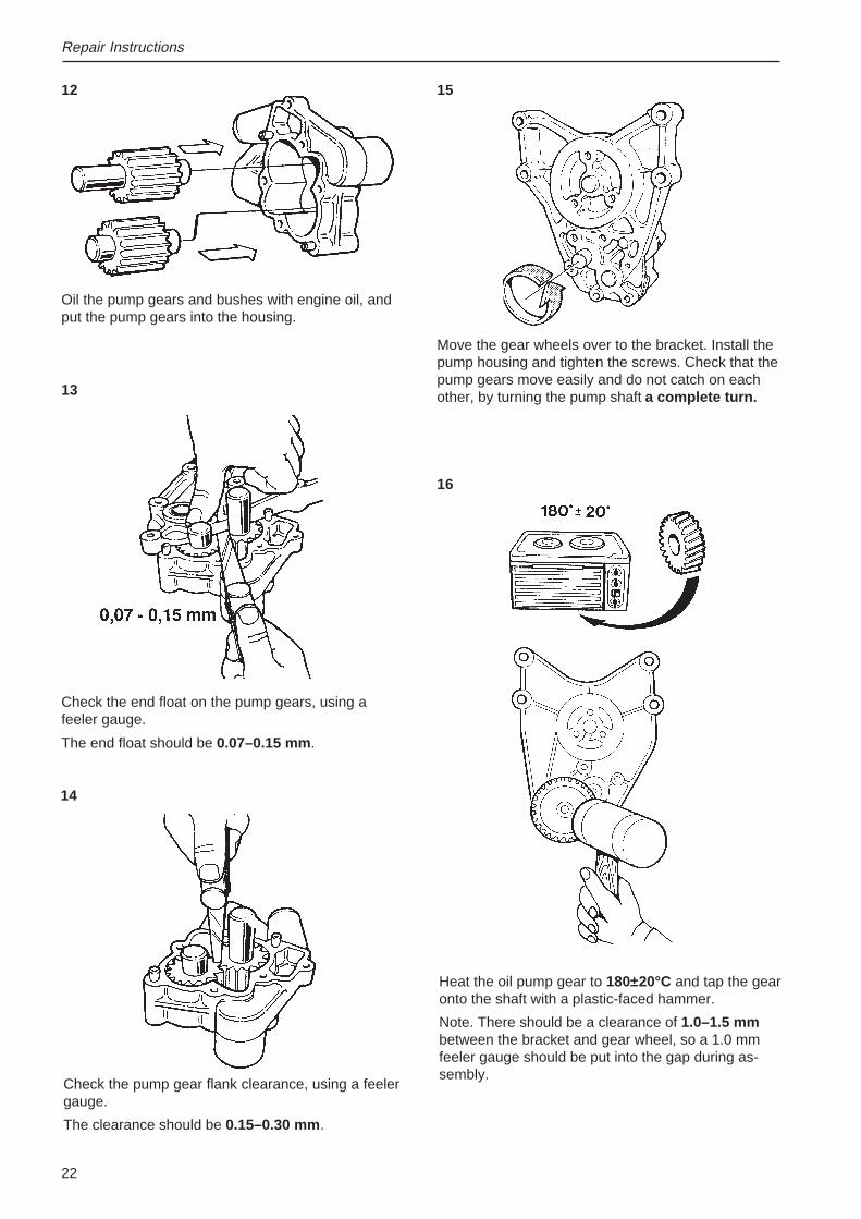
Check the pump gear flank clearance, using a feelergauge.
The clearance should be 0.15–0.30 mm .
Oil the pump gears and bushes with engine oil, andput the pump gears into the housing.
13
Check the end float on the pump gears, using afeeler gauge.
The end float should be 0.07–0.15 mm .
14
Move the gear wheels over to the bracket. Install thepump housing and tighten the screws. Check that thepump gears move easily and do not catch on eachother, by turning the pump shaft a complete turn.
Heat the oil pump gear to 180±20°C and tap the gearonto the shaft with a plastic-faced hammer.
Note. There should be a clearance of 1.0–1.5 mmbetween the bracket and gear wheel, so a 1.0 mmfeeler gauge should be put into the gap during as-sembly.
16
23
Repair Instructions
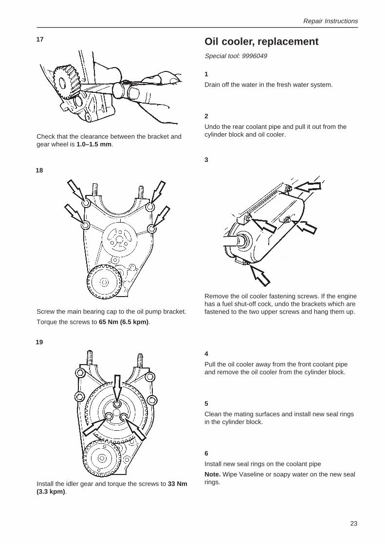
Oil cooler, replacementSpecial tool: 9996049
1
Drain off the water in the fresh water system.
2
Undo the rear coolant pipe and pull it out from thecylinder block and oil cooler.
17
3
Remove the oil cooler fastening screws. If the enginehas a fuel shut-off cock, undo the brackets which arefastened to the two upper screws and hang them up.
4
Pull the oil cooler away from the front coolant pipeand remove the oil cooler from the cylinder block.
5
Clean the mating surfaces and install new seal ringsin the cylinder block.
6
Install new seal rings on the coolant pipe
Note. Wipe Vaseline or soapy water on the new sealrings.
Check that the clearance between the bracket andgear wheel is 1.0–1.5 mm .
Screw the main bearing cap to the oil pump bracket.
Torque the screws to 65 Nm (6.5 kpm) .
18
19
Install the idler gear and torque the screws to 33 Nm(3.3 kpm) .
24
Repair Instructions
7
Press the oil cooler onto the front coolant pipe andscrew the oil cooler to the cylinder block.
8
Install the rear coolant pipe
Note: Fist press the coolant pipe into the oil cooler,then into the cylinder block.
9
Screw the rear coolant pipe to the cylinder block.
10
Top up with coolant and engine oil.
11
Run the engine with the start motor until the oil gaugegives a reading.
12
Start the engine and check for leakage around the oilcooler and connections.
Oil cooler, cleaning
1
Flush the coolant side of the oil cooler with degreas-er.
Clean the oil side with detergent.
The oil cooler must have the same temperature asthe test room for small leaks to be detected.
Flush the oil cooler with water at room temperatureuntil it has assumed room temperature.
Drain all water.
2
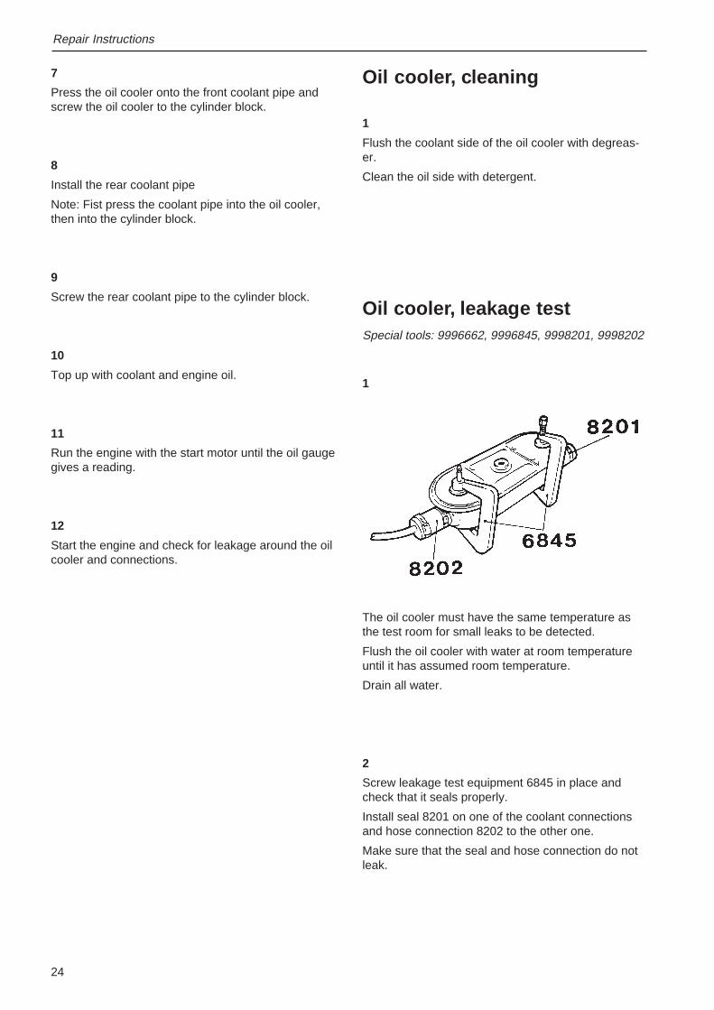
Screw leakage test equipment 6845 in place andcheck that it seals properly.
Install seal 8201 on one of the coolant connectionsand hose connection 8202 to the other one.
Make sure that the seal and hose connection do notleak.
Oil cooler, leakage testSpecial tools: 9996662, 9996845, 9998201, 9998202
1
25
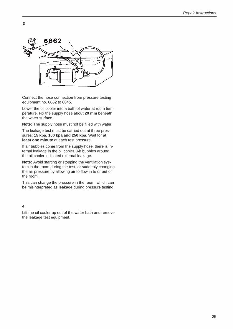
3
Connect the hose connection from pressure testingequipment no. 6662 to 6845.
Lower the oil cooler into a bath of water at room tem-perature. Fix the supply hose about 20 mm beneaththe water surface.
Note: The supply hose must not be filled with water.
The leakage test must be carried out at three pres-sures: 15 kpa, 100 kpa and 250 kpa . Wait for atleast one minute at each test pressure.
If air bubbles come from the supply hose, there is in-ternal leakage in the oil cooler. Air bubbles aroundthe oil cooler indicated external leakage.
Note: Avoid starting or stopping the ventilation sys-tem in the room during the test, or suddenly changingthe air pressure by allowing air to flow in to or out ofthe room.
This can change the pressure in the room, which canbe misinterpreted as leakage during pressure testing.
4
Lift the oil cooler up out of the water bath and removethe leakage test equipment.
Repair Instructions
26
References to service bulletins
........................................................................................................................................................................................
........................................................................................................................................................................................
........................................................................................................................................................................................
........................................................................................................................................................................................
........................................................................................................................................................................................
........................................................................................................................................................................................
........................................................................................................................................................................................
........................................................................................................................................................................................
........................................................................................................................................................................................
........................................................................................................................................................................................
........................................................................................................................................................................................
........................................................................................................................................................................................
........................................................................................................................................................................................
........................................................................................................................................................................................
........................................................................................................................................................................................
........................................................................................................................................................................................
........................................................................................................................................................................................
........................................................................................................................................................................................
........................................................................................................................................................................................
........................................................................................................................................................................................
........................................................................................................................................................................................
........................................................................................................................................................................................
........................................................................................................................................................................................
........................................................................................................................................................................................
........................................................................................................................................................................................
........................................................................................................................................................................................
........................................................................................................................................................................................
........................................................................................................................................................................................
........................................................................................................................................................................................
........................................................................................................................................................................................
........................................................................................................................................................................................
........................................................................................................................................................................................
........................................................................................................................................................................................
........................................................................................................................................................................................
Group No. Date Refers to


Report form
Do you have any complaints or other comments about this manual? Please makea copy of this page, write your comments down and post it to us. The address is atthe bottom of the page. We would prefer you to write in English or Swedish.
From: ............................................................................
......................................................................................
......................................................................................
......................................................................................
Refers to publication: .............................................................................................................................................
Publication no.: ..................................................................... Issued: ....................................................................
Suggestion/reasons: ..............................................................................................................................................
..............................................................................................................................................................................
..............................................................................................................................................................................
..............................................................................................................................................................................
..............................................................................................................................................................................
..............................................................................................................................................................................
..............................................................................................................................................................................
..............................................................................................................................................................................
..............................................................................................................................................................................
Date: ...........................................................
Name: .........................................................
AB Volvo PentaCustomer Support
Dept. 42200SE-405 08 Gothenburg
Sweden

773
6744
-9
Eng
lish
9–
2001