tamms-tasms installation instructionsdownloads.chiefmfg.com/manuals-i/tamms-tasms-i.pdfinstallation...
TRANSCRIPT

I N S T A L L A T I O N I N S T R U C T I O N S
TASMS withTS118TAMMS with TS318
Thinstall™ Steel Stud AdapterSpanish Product DescriptionGerman Product Description
Portuguese Product Description Italian Product DescriptionDutch Product Description
French Product Description
TASMS/TAMMS

TASMS/TAMMS Installation Instructions
2
DISCLAIMERMilestone AV Technologies and its affiliated corporations andsubsidiaries (collectively “Milestone”), intend to make thismanual accurate and complete. However, Milestone makes noclaim that the information contained herein covers all details,conditions or variations, nor does it provide for every possiblecontingency in connection with the installation or use of thisproduct. The information contained in this document is subjectto change without notice or obligation of any kind. Milestonemakes no representation of warranty, expressed or implied,regarding the information contained herein. Milestone assumesno responsibility for accuracy, completeness or sufficiency ofthe information contained in this document.
Chief® and Thinstall™ are registered trademarks of MilestoneAV Technologies. All rights reserved.
DEFINITIONSMOUNTING SYSTEM: A MOUNTING SYSTEM is theprimary Chief product to which an accessory and/or componentis attached.
ACCESSORY: AN ACCESSORY is the secondary Chiefproduct which is attached to a primary Chief product, and mayhave a component attached or setting on it.
COMPONENT: A COMPONENT is an audiovisual itemdesigned to be attached or resting on an accessory or mountingsystem such as a video camera, CPU, screen, display,projector, etc.
WARNING: A WARNING alerts you to the possibility ofserious injury or death if you do not follow the instructions.
CAUTION: A CAUTION alerts you to the possibility ofdamage or destruction of equipment if you do not follow thecorresponding instructions.
IMPORTANT SAFETY INSTRUCTIONS
WARNING: Failure to read, thoroughly understand, andfollow all instructions can result in serious personal injury,damage to equipment, or voiding of factory warranty! It is theinstaller’s responsibility to make sure all accessories areproperly assembled and installed using the instructionsprovided.
WARNING: Failure to provide adequate structural strengthfor this accessory can result in serious personal injury ordamage to equipment! It is the installer’s responsibility tomake sure the structure to which this accessory is attachedcan support five times the combined weight of all equipment.Reinforce the structure as required before installing theaccessory. The wall to which the mounting system /accessory is being attached may have a maximum drywallthickness of 5/8” (1.6cm). Do not install drywall anchors intothe seam between drywall pieces.
WARNING: Exceeding the weight capacity can result inserious personal injury or damage to equipment! It is theinstaller’s responsibility to make sure the combined weight ofall components attached to this accessory does not exceed50 lbs (22.67 kg) OR the weight capacity of the mountingsystem being used.
WARNING: Use this accessory only for its intended use asdescribed in these instructions. Do not use attachments notrecommended by the manufacturer.
WARNING: Never operate this accessory if it is damaged.Return the accessory to a service center for examination andrepair.
WARNING: Do not use this accessory outdoors.
IMPORTANT ! : The TASMS/TAMMS accessory is designedto be mounted to a 2" x 4"-25ga minimum steel studs wall.IMPORTANT ! : The TASMS/TAMMS accessory isdesigned to mount Chief’s Thinstall™ single stud wallmounting systems to a steel studs wall. Do not attempt toinstall any other mounting system to this accessory.
--SAVE THESE INSTRUCTIONS--
Installation Instructions TASMS/TAMMS
3
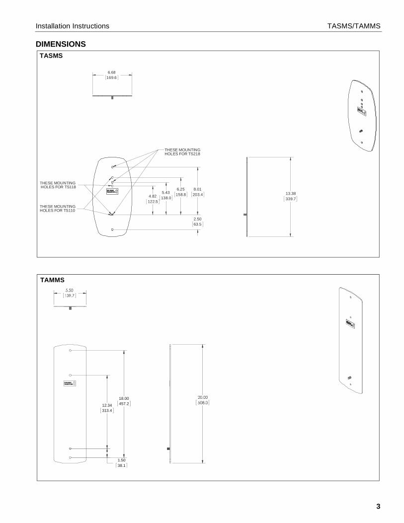
DIMENSIONS
4.82122.5
5.43138.0
6.25158.8
2.5063.5
8.01203.4
THESE MOUNTING HOLES FOR TS118
THESE MOUNTINGHOLES FOR TS110
THESE MOUNTINGHOLES FOR TS218
13.38339.7
6.68169.6
TASMS
18.00457.212.34
313.4
1.5038.1
TAMMS
TASMS/TAMMS Installation Instructions
4
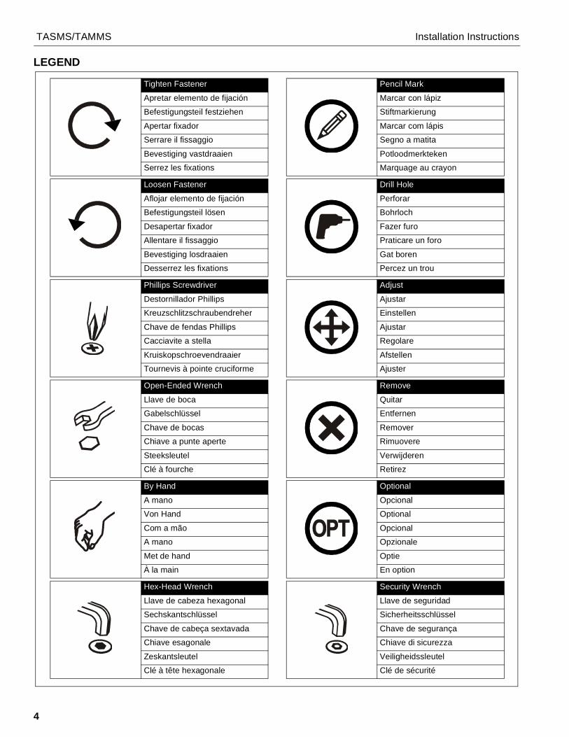
LEGEND
Tighten Fastener
Apretar elemento de fijación
Befestigungsteil festziehen
Apertar fixador
Serrare il fissaggio
Bevestiging vastdraaien
Serrez les fixations
Loosen Fastener
Aflojar elemento de fijación
Befestigungsteil lösen
Desapertar fixador
Allentare il fissaggio
Bevestiging losdraaien
Desserrez les fixations
Phillips Screwdriver
Destornillador Phillips
Kreuzschlitzschraubendreher
Chave de fendas Phillips
Cacciavite a stella
Kruiskopschroevendraaier
Tournevis à pointe cruciforme
Open-Ended Wrench
Llave de boca
Gabelschlüssel
Chave de bocas
Chiave a punte aperte
Steeksleutel
Clé à fourche
By Hand
A mano
Von Hand
Com a mão
A mano
Met de hand
À la main
Hex-Head Wrench
Llave de cabeza hexagonal
Sechskantschlüssel
Chave de cabeça sextavada
Chiave esagonale
Zeskantsleutel
Clé à tête hexagonale
Pencil Mark
Marcar con lápiz
Stiftmarkierung
Marcar com lápis
Segno a matita
Potloodmerkteken
Marquage au crayon
Drill Hole
Perforar
Bohrloch
Fazer furo
Praticare un foro
Gat boren
Percez un trou
Adjust
Ajustar
Einstellen
Ajustar
Regolare
Afstellen
Ajuster
Remove
Quitar
Entfernen
Remover
Rimuovere
Verwijderen
Retirez
Optional
Opcional
Optional
Opcional
Opzionale
Optie
En option
Security Wrench
Llave de seguridad
Sicherheitsschlüssel
Chave de segurança
Chiave di sicurezza
Veiligheidssleutel
Clé de sécurité

Installation Instructions TASMS/TAMMS
5
TOOLS REQUIRED FOR INSTALLATION
PARTS
#21/2" (12.7mm)
1/2" (12.7mm)
A (1)[Adapter plate]
B (4)1/4-20 x 1 3/4"
C (4)1/4"
D (4)1/4" anchor
F (2)[screw cap]
E (1)1/4-20
Hardware bag (only 3 of each required)
(TASMS) or (TAMMS)
G (1)1/4"

TASMS/TAMMS Installation Instructions
6
Site Requirements
(Must be centered over stud)
Drywall
**1/2" minimumDrywall Thickness
FRONT
(Both Sides of Stud)
There must be a minimum of1-7/8" (48mm) clearanceinside wall
If back side of wall is unfinished, drywall must be installedto a minimum of one stud left and right of the studsbeing used to install the mount. Drywall must besecured to stud with screws 12" on center
Steel Stud (2 x 4 / 25ga minimum)Stud type and structural strength must conform to the North AmericanSpecification for the Design of Cold-Formed Steel Structural Members.
**See hazard statementon page 2!
[362, 125 18, C-Shape, S - Stud Section]

Installation Instructions TASMS/TAMMS
7
Assembly And InstallationIMPORTANT ! : The TASMS/TAMMS accessory isdesigned to mount Chief’s Thinstall™ wall mountingsystems to a steel studs wall. Do not attempt to installany other mounting system to this accessory.1. Hold adapter plate (A) up to the wall on top of steel stud at
desired mounting location. (See Figure 1) or (See Figure 2)
2. Mark three hole locations. The middle hole to use will varybased on which mounting system is being used on theTASMS. (See Figure 1) or (See Figure 2)
3. Drill a 1/2" (12.7mm) hole at the desired mounting locations.(See Figure 1) or (See Figure 2)
Figure 1
Figure 2
4. Hold metal channel on anchor (D) flat alongside plasticstraps and slide channel through hole. (See Figure 3)
Figure 3
5. Holding plastic straps on anchor (D), pull anchor away fromwall until channel rests flush behind wall making sureanchor channel is positioned vertically on stud. (See Figure4)
6. Slide plastic cap on anchor (D) towards wall until flange ofcap is flush with wall. (See Figure 4)
Figure 4
7. Snap off plastic straps on anchor at wall by pushing side toside, snapping off straps level with flange of plastic cap.(See Figure 5)
8. Repeat Steps 3 through 7 for the other mounting hole.
Figure 5
2 3
1/2" (12.7mm)
(A)
TS110
TS218
TS118
(TASMS)
2 3
1/2"‘1 (12.7mm)
(TAMMS)
(A)
(D)
Drywall
Plastic Straps 4
(D)
Plastic Cap
Drywall
Anchor Metal ChannelSIDE VIEW
5
Steel Stud
6
Plastic Straps
Drywall
Anchor Metal Channel
Plastic Cap
SIDE VIEW
7
Steel Stud

TASMS/TAMMS Installation Instructions
8
9. Place adapter plate (A) over anchors and align mountingholes on mount with holes in anchors. (See Figure 6) or(See Figure 7)
10. Use two 1/4-20 x 1 3/4" Phillips pan machine screws (B),two screw caps (F) and two 1/4" washers (C) to secureadapter plate (A) to anchors (D) using top and bottommounting holes. (See Figure 6) or (See Figure 7)
Figure 6
Figure 7
11. Use 1/4-20 hex nut (E) to secure Thinstall mounting systemto adapter plate (A). (See Figure 8) or (See Figure 9)
12. Use 1/4-20 x 1 3/4" Phillips pan machine screw (B) and 1/4"washer (C) to secure Thinstall™ mounting system toadapter plate (A). (See Figure 8) or (See Figure 9)
Figure 8
Figure 9
13. Install Thinstall™ mount to wall plate following Thinstall™installation instructions.
(B) x 2
(D) x 2
(C) x 2
(A)
10 (F) x 2 (TASMS)
(B) x 2
(D) x 2
(A)
10
(F) x 2
(C) x 2
(TAMMS) (F)11
12 (B)
TS110 shown
(A)
(C)
(TASMS)
(TAMMS)
(F)11
12 (B)
(A)TS318
(C)

Installation Instructions TASMS/TAMMS
9

TASMS/TAMMS Installation Instructions
10

Installation Instructions TASMS/TAMMS
11

TASMS/TAMMS Installation Instructions
USA/International A 6436 City West Parkway, Eden Prairie, MN 55344P 800.582.6480 / 952.225.6000F 877.894.6918 / 952.894.6918
Europe A Franklinstraat 14, 6003 DK Weert, NetherlandsP +31 (0) 495 580 852F +31 (0) 495 580 845
Asia Pacific A Office No. 918 on 9/F, Shatin Galleria18-24 Shan Mei StreetFotan, Shatin, Hong Kong
P 852 2145 4099F 852 2145 4477
Chief, a products division ofMilestone AV Technologies
8800-002956 Rev012017 Milestone AV Technologies
www.milestone.com05/17