tampa electric integrated gasification combined-cycle...
TRANSCRIPT
Tampa ElectricIntegrated Gasification
Combined-Cycle ProjectAn Update
TOPICAL REPORT NUMBER 19 JULY 2000
TOPICAL REPORT NUMBER 19
A report on a project conducted jointly undera cooperative agreement between:
The U.S. Department of Energy andTampa Electric Company
July 2000
The Tampa ElectricIntegrated GasificationCombined-Cycle ProjectAn Update

Cover image: The Polk Power Plant site as seen from across the lake in early evening. Photography
courtesy of Lee Schmoe, Bechtel Power Corporation.
The Tampa ElectricIntegrated GasificationCombined-Cycle Project
Executive Summary ........................................................................................... 1
Background........................................................................................................ 2
Project Description ............................................................................................ 5
Power Plant Description .................................................................................... 7
Environmental Considerations .......................................................................... 9
Cost/Schedule .................................................................................................. 12
Project Objective ............................................................................................. 12
Plant Modifications/Improvements ................................................................. 12
Results ............................................................................................................. 14
Awards ............................................................................................................. 15
Commercial Applications ................................................................................ 15
Future Developments ....................................................................................... 17
Market Potential .............................................................................................. 18
Conclusions ..................................................................................................... 19
Bibliography .................................................................................................... 20
Contacts for CCT Projects and U.S. DOE CCT Program ............................... 23
List of Acronyms and Abbreviations .............................................................. 24
1
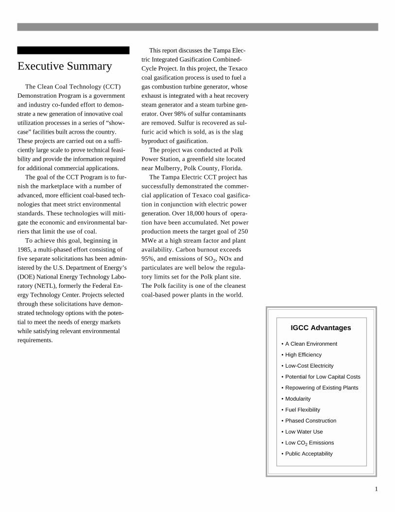
IGCC Advantages
• A Clean Environment
• High Efficiency
• Low-Cost Electricity
• Potential for Low Capital Costs
• Repowering of Existing Plants
• Modularity
• Fuel Flexibility
• Phased Construction
• Low Water Use
• Low CO2 Emissions
• Public Acceptability
Executive Summary
The Clean Coal Technology (CCT)Demonstration Program is a government
and industry co-funded effort to demon-
strate a new generation of innovative coalutilization processes in a series of “show-
case” facilities built across the country.
These projects are carried out on a suffi-ciently large scale to prove technical feasi-
bility and provide the information required
for additional commercial applications.The goal of the CCT Program is to fur-
nish the marketplace with a number of
advanced, more efficient coal-based tech-nologies that meet strict environmental
standards. These technologies will miti-
gate the economic and environmental bar-riers that limit the use of coal.
To achieve this goal, beginning in
1985, a multi-phased effort consisting offive separate solicitations has been admin-
istered by the U.S. Department of Energy’s
(DOE) National Energy Technology Labo-ratory (NETL), formerly the Federal En-
ergy Technology Center. Projects selected
through these solicitations have demon-strated technology options with the poten-
tial to meet the needs of energy markets
while satisfying relevant environmentalrequirements.
This report discusses the Tampa Elec-
tric Integrated Gasification Combined-Cycle Project. In this project, the Texaco
coal gasification process is used to fuel a
gas combustion turbine generator, whoseexhaust is integrated with a heat recovery
steam generator and a steam turbine gen-
erator. Over 98% of sulfur contaminantsare removed. Sulfur is recovered as sul-
furic acid which is sold, as is the slag
byproduct of gasification.The project was conducted at Polk
Power Station, a greenfield site located
near Mulberry, Polk County, Florida.The Tampa Electric CCT project has
successfully demonstrated the commer-
cial application of Texaco coal gasifica-tion in conjunction with electric power
generation. Over 18,000 hours of opera-
tion have been accumulated. Net powerproduction meets the target goal of 250
MWe at a high stream factor and plant
availability. Carbon burnout exceeds95%, and emissions of SO2, NOx and
particulates are well below the regula-
tory limits set for the Polk plant site.The Polk facility is one of the cleanest
coal-based power plants in the world.
2
Background
The Clean Coal Technology (CCT)
Demonstration Program, sponsored by
the U.S. Department of Energy (DOE)
and administered by the National Energy
Technology Laboratory (NETL), has been
conducted since 1985 to develop innova-
tive, environmentally friendly coal utili-
zation processes for the world energy
marketplace.
The CCT Program, which is co-funded
by industry and government, involves a
series of commercial-scale demonstration
projects that provide data for design, con-
struction, operation, and technical/eco-
nomic evaluation of full-scale applica-
tions. The goal of the CCT Program is
to enhance the utilization of coal as a ma-
jor energy source.
The CCT Program has also opened
a channel to policy-making bodies by
providing data from cutting-edge tech-
nologies to aid in formulating regulatory
decisions. DOE and the participants in
several CCT projects have provided the
Environmental Protection Agency (EPA)
with data to help establish emissions tar-
gets for nitrogen oxide (NOx) emissions
from coal-fired boilers subject to compli-
ance under the 1990 Clean Air Act
Amendments (CAAA).
The Tampa ElectricIntegrated GasificationCombined-Cycle Project
3
Integrated GasificationCombined-Cycle
Among the technologies being demon-
strated in the CCT Program is IntegratedGasification Combined-Cycle (IGCC).
IGCC is an innovative electric power gen-
eration process that combines modern coalgasification with gas turbine and steam
power generation technologies. IGCC is
one of the most efficient and cleanest ofavailable technologies for coal-based elec-
tric power generation. This technology of-
fers high system efficiencies, low costs,and very low pollution levels.
IGCC power plants offer excellent envi-
ronmental performance. Gasificationbreaks down virtually any carbon-based
feedstock into its basic constituents, enabling
the separation of pollutants to produce clean
gas for efficient electricity generation. As a
result, atmospheric emissions of pollutants
are very low. Water use is lower than con-
ventional coal-based generation because gas
turbine units require no cooling water, an es-
pecially important consideration in areas of
limited water resources. Due to their high
efficiency, less coal is used, causing IGCC
power plants to emit less carbon dioxide
(CO2) to the atmosphere, thereby decreasing
concerns about climate change. Less coal use
also results in less ash requiring disposal.
Modularity and fuel flexibility are impor-
tant attributes of IGCC power plants. The
combined-cycle unit can be operated on other
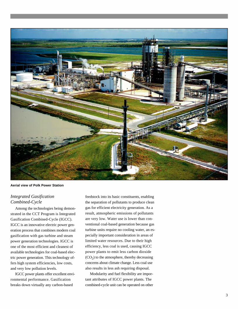
Aerial view of Polk Power Station
4
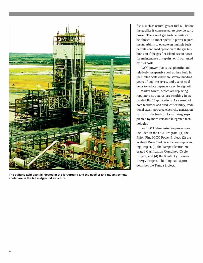
The sulfuric acid plant is located in the foreground and the gasifier and radiant syngascooler are in the tall midground structure
fuels, such as natural gas or fuel oil, before
the gasifier is constructed, to provide earlypower. The size of gas turbine units can
be chosen to meet specific power require-
ments. Ability to operate on multiple fuelspermits continued operation of the gas tur-
bine unit if the gasifier island is shut down
for maintenance or repairs, or if warrantedby fuel costs.
IGCC power plants use plentiful and
relatively inexpensive coal as their fuel. Inthe United States there are several hundred
years of coal reserves, and use of coal
helps to reduce dependence on foreign oil.Market forces, which are replacing
regulatory structures, are resulting in ex-
panded IGCC applications. As a result ofboth feedstock and product flexibility, tradi-
tional steam-powered electricity generation
using single feedstocks is being sup-planted by more versatile integrated tech-
nologies.
Four IGCC demonstration projects areincluded in the CCT Program: (1) the
Piñon Pine IGCC Power Project, (2) the
Wabash River Coal Gasification Repower-ing Project, (3) the Tampa Electric Inte-
grated Gasification Combined-Cycle
Project, and (4) the Kentucky PioneerEnergy Project. This Topical Report
describes the Tampa Project.
5
Tampa Electric Company Owner/operator
TECO Power Services Corporation Project management and commercialization
Texaco Development Corporation Licensor of gasification technology
General Electric Corporation Supplier of gas turbine/combined-cycle equipment
Bechtel Power Corporation Detailed engineering/constructionmanagement services, procurement,and startup
MAN Gutehoffnüngshutte AG Supplier of radiant syngas cooling system
L. & C. Steinmüller Gmbh Supplier of convective syngas cooling system
Air Products & Chemicals, Inc. Turnkey supplier for air separation unit
Monsanto Enviro-Chem Systems, Inc. Turnkey supplier for sulfuric acid plant
H.B. Zachry Company Power block construction
The Industrial Company Gasification area construction
Johnson Brothers Corporation Site development and civil contractor
Aqua-Chem, Inc. Supplier of brine concentration plant
Davenport Mammoet Transportation/erection of radiantHeavy Transport syngas cooler
Major Participants
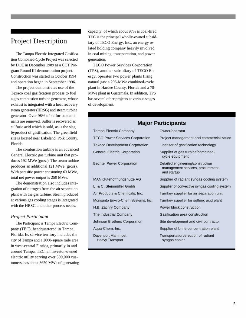
Project Description
The Tampa Electric Integrated Gasifica-tion Combined-Cycle Project was selected
by DOE in December 1989 as a CCT Pro-
gram Round III demonstration project.Construction was started in October 1994
and operation began in September 1996.
The project demonstrates use of theTexaco coal gasification process to fuel
a gas combustion turbine generator, whose
exhaust is integrated with a heat recoverysteam generator (HRSG) and steam turbine
generator. Over 98% of sulfur contami-
nants are removed. Sulfur is recovered assulfuric acid which is sold, as is the slag
byproduct of gasification. The greenfield
site is located near Lakeland, Polk County,Florida.
The combustion turbine is an advanced
General Electric gas turbine unit that pro-duces 192 MWe (gross). The steam turbine
produces an additional 121 MWe (gross).
With parasitic power consuming 63 MWe,total net power output is 250 MWe.
The demonstration also includes inte-
gration of nitrogen from the air separationplant with the gas turbine. Steam produced
at various gas cooling stages is integrated
with the HRSG and other process needs.
Project ParticipantThe Participant is Tampa Electric Com-
pany (TEC), headquartered in Tampa,
Florida. Its service territory includes thecity of Tampa and a 2000-square mile area
in west-central Florida, primarily in and
around Tampa. TEC, an investor-ownedelectric utility serving over 500,000 cus-
tomers, has about 3650 MWe of generating
capacity, of which about 97% is coal-fired.
TEC is the principal wholly-owned subsid-iary of TECO Energy, Inc., an energy re-
lated holding company heavily involved
in coal mining, transportation, and powergeneration.
TECO Power Services Corporation
(TPS), another subsidiary of TECO En-ergy, operates two power plants firing
natural gas: a 295-MWe combined-cycle
plant in Hardee County, Florida and a 78-MWe plant in Guatemala. In addition, TPS
has several other projects at various stages
of development.
6
Project SubcontractorsOther participants in the CCT project
are major technology suppliers, including
Texaco Development Company, the licen-sor of the coal gasification process; Gen-
eral Electric Corporation, the supplier of
the combined-cycle technology; Air Prod-ucts and Chemicals, Inc., supplier of the air
separation unit; Monsanto Enviro-Chem
Systems, Inc., supplier of the sulfuric acidplant; TPS, project manager and marketer;
and Bechtel Power Corporation, who pro-
vided detailed engineering and construc-tion management services.
Site DescriptionThe demonstration unit is Unit 1 of the
Polk Power Plant, a new facility built in
1996 and located near Mulberry in southcentral Polk County, Florida. The 4300-
acre site is about 45 miles southeast of
Tampa and 17 miles south of Lakeland,in the heart of central Florida’s phosphate
mining region.
The Polk site is on a tract of land thathad been previously mined for phosphate
rock, and has been redeveloped and reveg-
etated by TEC for this project.The area is predominantly rural. Polk
County is an important citrus-raising and
phosphate mining center, each being im-portant Florida industries.
About one-third of the site is used for
power generation facilities. Another third,about 1500 acres, is used to enhance the
environment by creation of public fishing
lakes for the Florida Fish and Game Com-mission. This area was converted from
phosphate mining spoils to wetlands and
uplands, thereby providing habitat for na-tive plants and animals, and was trans-
ferred to the Commission in 1997. The
final third of the site is used primarily foraccess and to provide a visual buffer.
The site contains an 850-acre cooling
reservoir. State Highway 37 crosses thesite about one mile from the IGCC power
plant.
Makeup water for the power plant isprovided from on-site wells. All process
water is recycled.
Coal SupplyCoal is delivered to the site by truck
from a transloading facility at TEC’s Big
Bend Station in Apollo Beach, Florida.Coals tested include Illinois No. 6, Pitts-
burgh No. 8, Kentucky No. 9, and Ken-
tucky No. 11, all bituminous coals havinga sulfur content ranging from 2.5-3.5%.
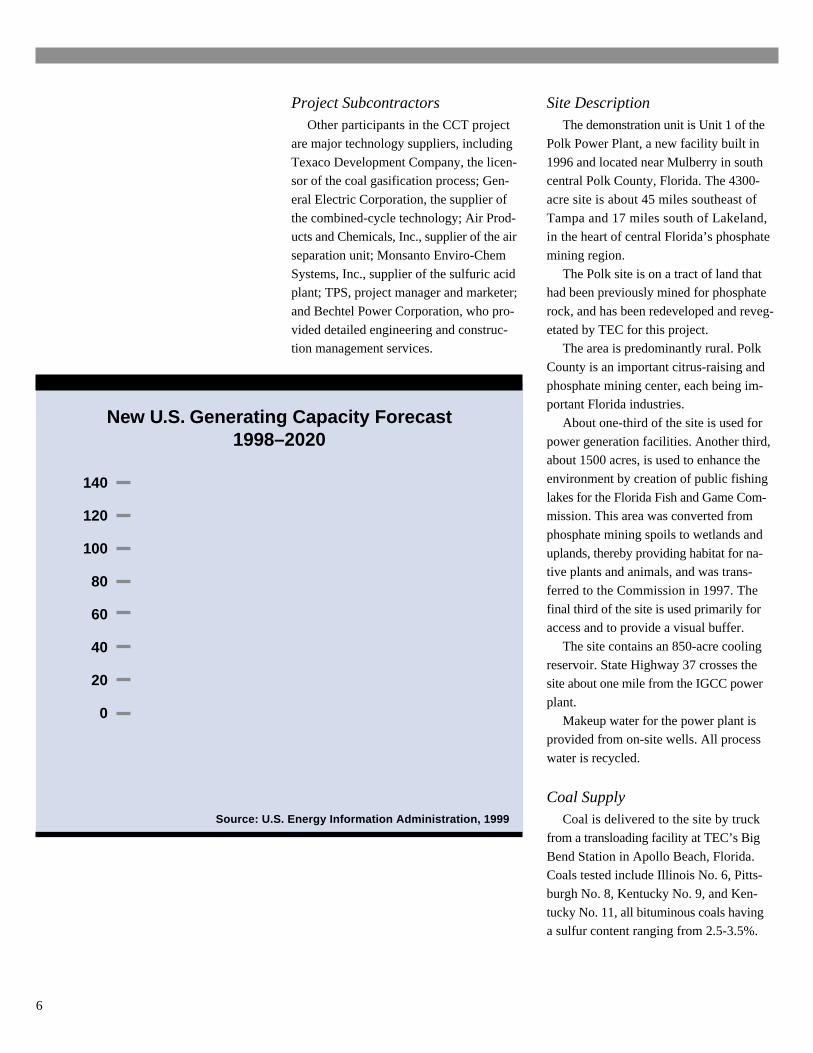
New U.S. Generating Capacity Forecast1998–2020
Source: U.S. Energy Information Administration, 1999
140
120
100
80
60
40
20
0RenewablesCombustion
TurbinesCombined
CycleFossilSteam
Cap
acit
y, G
We
Includes non-utility generators and cogenerators
7
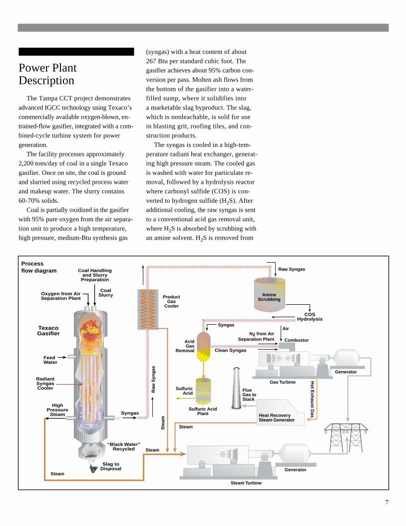
Processflow diagram
Power PlantDescription
The Tampa CCT project demonstrates
advanced IGCC technology using Texaco’s
commercially available oxygen-blown, en-trained-flow gasifier, integrated with a com-
bined-cycle turbine system for power
generation.The facility processes approximately
2,200 tons/day of coal in a single Texaco
gasifier. Once on site, the coal is groundand slurried using recycled process water
and makeup water. The slurry contains
60-70% solids.Coal is partially oxidized in the gasifier
with 95% pure oxygen from the air separa-
tion unit to produce a high temperature,high pressure, medium-Btu synthesis gas
(syngas) with a heat content of about
267 Btu per standard cubic foot. Thegasifier achieves about 95% carbon con-
version per pass. Molten ash flows from
the bottom of the gasifier into a water-filled sump, where it solidifies into
a marketable slag byproduct. The slag,
which is nonleachable, is sold for usein blasting grit, roofing tiles, and con-
struction products.
The syngas is cooled in a high-tem-perature radiant heat exchanger, generat-
ing high pressure steam. The cooled gas
is washed with water for particulate re-moval, followed by a hydrolysis reactor
where carbonyl sulfide (COS) is con-
verted to hydrogen sulfide (H2S). Afteradditional cooling, the raw syngas is sent
to a conventional acid gas removal unit,
where H2S is absorbed by scrubbing withan amine solvent. H2S is removed from
Steam
Coal Handlingand Slurry
Preparation
COSHydrolysis
Steam
CombustorN2 from Air
Separation Plant
Ho
t Exh
aust G
as
FlueGas toStack
Gas Turbine
Steam Turbine
SteamSte
am
Generator
Generator
Sulfuric AcidPlant
Raw
Syn
gas
Raw Syngas
Syngas
AcidGas
Removal
AmineScrubbing
Clean Syngas
ProductGas
Cooler
Heat RecoverySteam Generator
SulfuricAcid
Air
Slag toDisposal
RadiantSyngasCooler
CoalSlurry
FeedWater
“Black Water”Recycled
Oxygen from AirSeparation Plant
HighPressure
Steam
TexacoGasifier
Syngas
8
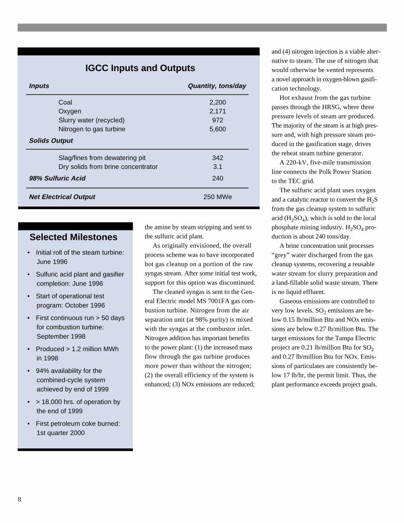
IGCC Inputs and Outputs
Inputs Quantity, tons/day
Coal 2,200Oxygen 2,171Slurry water (recycled) 972Nitrogen to gas turbine 5,600
Solids Output
Slag/fines from dewatering pit 342Dry solids from brine concentrator 3.1
98% Sulfuric Acid 240
Net Electrical Output 250 MWe
Selected Milestones
• Initial roll of the steam turbine:June 1996
• Sulfuric acid plant and gasifiercompletion: June 1996
• Start of operational testprogram: October 1996
• First continuous run > 50 daysfor combustion turbine:September 1998
• Produced > 1.2 million MWhin 1998
• 94% availability for thecombined-cycle systemachieved by end of 1999
• > 18,000 hrs. of operation bythe end of 1999
• First petroleum coke burned:1st quarter 2000
the amine by steam stripping and sent to
the sulfuric acid plant.As originally envisioned, the overall
process scheme was to have incorporated
hot gas cleanup on a portion of the rawsyngas stream. After some initial test work,
support for this option was discontinued.
The cleaned syngas is sent to the Gen-eral Electric model MS 7001FA gas com-
bustion turbine. Nitrogen from the air
separation unit (at 98% purity) is mixedwith the syngas at the combustor inlet.
Nitrogen addition has important benefits
to the power plant: (1) the increased massflow through the gas turbine produces
more power than without the nitrogen;
(2) the overall efficiency of the system isenhanced; (3) NOx emissions are reduced;
and (4) nitrogen injection is a viable alter-
native to steam. The use of nitrogen thatwould otherwise be vented represents
a novel approach in oxygen-blown gasifi-
cation technology.Hot exhaust from the gas turbine
passes through the HRSG, where three
pressure levels of steam are produced.The majority of the steam is at high pres-
sure and, with high pressure steam pro-
duced in the gasification stage, drivesthe reheat steam turbine generator.
A 220-kV, five-mile transmission
line connects the Polk Power Stationto the TEC grid.
The sulfuric acid plant uses oxygen
and a catalytic reactor to convert the H2Sfrom the gas cleanup system to sulfuric
acid (H2SO4), which is sold to the local
phosphate mining industry. H2SO4 pro-duction is about 240 tons/day.
A brine concentration unit processes
“grey” water discharged from the gascleanup systems, recovering a reusable
water stream for slurry preparation and
a land-fillable solid waste stream. Thereis no liquid effluent.
Gaseous emissions are controlled to
very low levels. SO2 emissions are be-low 0.15 lb/million Btu and NOx emis-
sions are below 0.27 lb/million Btu. The
target emissions for the Tampa Electricproject are 0.21 lb/million Btu for SO2
and 0.27 lb/million Btu for NOx. Emis-
sions of particulates are consistently be-low 17 lb/hr, the permit limit. Thus, the
plant performance exceeds project goals.
9
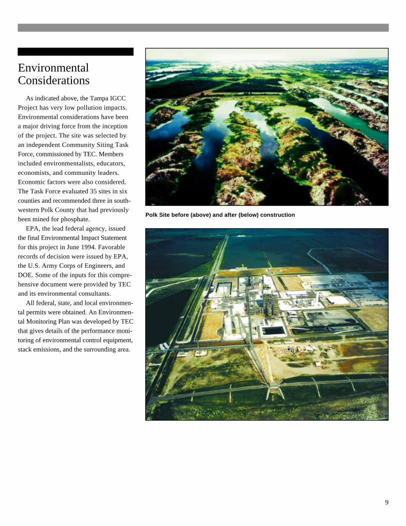
Polk Site before (above) and after (below) construction
EnvironmentalConsiderations
As indicated above, the Tampa IGCC
Project has very low pollution impacts.
Environmental considerations have beena major driving force from the inception
of the project. The site was selected by
an independent Community Siting TaskForce, commissioned by TEC. Members
included environmentalists, educators,
economists, and community leaders.Economic factors were also considered.
The Task Force evaluated 35 sites in six
counties and recommended three in south-western Polk County that had previously
been mined for phosphate.
EPA, the lead federal agency, issuedthe final Environmental Impact Statement
for this project in June 1994. Favorable
records of decision were issued by EPA,the U.S. Army Corps of Engineers, and
DOE. Some of the inputs for this compre-
hensive document were provided by TECand its environmental consultants.
All federal, state, and local environmen-
tal permits were obtained. An Environmen-tal Monitoring Plan was developed by TEC
that gives details of the performance moni-
toring of environmental control equipment,stack emissions, and the surrounding area.
10
Process Description
Coal Gasification
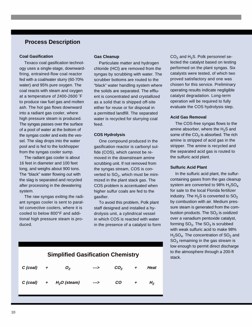
Texaco coal gasification technol-ogy uses a single-stage, downward-firing, entrained-flow coal reactorfed with a coal/water slurry (60-70%water) and 95% pure oxygen. Thecoal reacts with steam and oxygenat a temperature of 2400-2600 °Fto produce raw fuel gas and moltenash. The hot gas flows downwardinto a radiant gas cooler, wherehigh pressure steam is produced.The syngas passes over the surfaceof a pool of water at the bottom ofthe syngas cooler and exits the ves-sel. The slag drops into the waterpool and is fed to the lockhopperfrom the syngas cooler sump.
The radiant gas cooler is about16 feet in diameter and 100 feetlong, and weighs about 900 tons.The “black” water flowing out withthe slag is separated and recycledafter processing in the dewateringsystem.
The raw syngas exiting the radi-ant syngas cooler is sent to paral-lel convective coolers, where it iscooled to below 800°F and addi-tional high pressure steam is pro-duced.
Gas Cleanup
Particulate matter and hydrogenchloride (HCl) are removed from thesyngas by scrubbing with water. Thescrubber bottoms are routed to the“black” water handling system wherethe solids are separated. The efflu-ent is concentrated and crystallizedas a solid that is shipped off-siteeither for reuse or for disposal ina permitted landfill. The separatedwater is recycled for slurrying coalfeed.
COS Hydrolysis
One compound produced in thegasification reactor is carbonyl sul-fide (COS), which cannot be re-moved in the downstream aminescrubbing unit. If not removed fromthe syngas stream, COS is con-verted to SO2, which must be mini-mized in the plant stack gas. TheCOS problem is accentuated whenhigher sulfur coals are fed to thegasifier.
To avoid this problem, Polk plantstaff designed and installed a hy-drolysis unit, a cylindrical vesselin which COS is reacted with waterin the presence of a catalyst to form
CO2 and H2S. Polk personnel se-lected the catalyst based on testingperformed on the plant syngas. Sixcatalysts were tested, of which twoproved satisfactory and one waschosen for this service. Preliminaryoperating results indicate negligiblecatalyst degradation. Long-termoperation will be required to fullyevaluate the COS hydrolysis step.
Acid Gas Removal
The COS-free syngas flows to theamine absorber, where the H2S andsome of the CO2 is absorbed. The richamine is stripped of acid gas in thestripper. The amine is recycled andthe separated acid gas is routed tothe sulfuric acid plant.
Sulfuric Acid Plant
In the sulfuric acid plant, the sulfur-containing gases from the gas cleanupsystem are converted to 98% H2SO4
for sale to the local Florida fertilizerindustry. The H2S is converted to SO2
by combustion with air. Medium pres-sure steam is generated from the com-bustion products. The SO2 is oxidizedover a vanadium pentoxide catalyst,forming SO3. The SO3 is scrubbedwith weak sulfuric acid to make 98%H2SO4. The concentration of SO2 andSO3 remaining in the gas stream islow enough to permit direct dischargeto the atmosphere through a 200-ftstack.
C (coal) + O2 ---> CO2 + Heat
C (coal) + H2O (steam) ---> CO + H2
Simplified Gasification Chemistry
11
Power Block
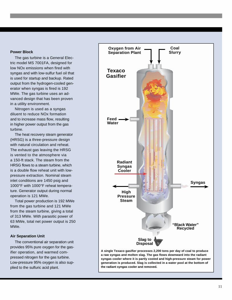
The gas turbine is a General Elec-tric model MS 7001FA, designed forlow NOx emissions when fired withsyngas and with low-sulfur fuel oil thatis used for startup and backup. Ratedoutput from the hydrogen-cooled gen-erator when syngas is fired is 192MWe. The gas turbine uses an ad-vanced design that has been provenin a utility environment.
Nitrogen is used as a syngasdiluent to reduce NOx formationand to increase mass flow, resultingin higher power output from the gasturbine.
The heat recovery steam generator(HRSG) is a three-pressure designwith natural circulation and reheat.The exhaust gas leaving the HRSGis vented to the atmosphere viaa 150-ft stack. The steam from theHRSG flows to a steam turbine, whichis a double flow reheat unit with low-pressure extraction. Nominal steaminlet conditions are 1450 psig and1000°F with 1000°F reheat tempera-ture. Generator output during normaloperation is 121 MWe.
Total power production is 192 MWefrom the gas turbine and 121 MWefrom the steam turbine, giving a totalof 313 MWe. With parasitic power of63 MWe, total net power output is 250MWe.
Air Separation Unit
The conventional air separation unitprovides 95% pure oxygen for the gas-ifier operation, and warmed com-pressed nitrogen for the gas turbine.Low-pressure 95% oxygen is also sup-plied to the sulfuric acid plant.
A single Texaco gasifier processes 2,200 tons per day of coal to producea raw syngas and molten slag. The gas flows downward into the radiantsyngas cooler where it is partly cooled and high-pressure steam for powergeneration is produced. Slag is collected in a water pool at the bottom ofthe radiant syngas cooler and removed.
RadiantSyngasCooler
CoalSlurry
FeedWater
“Black Water”Recycled
Oxygen from AirSeparation Plant
HighPressure
Steam
TexacoGasifier
Syngas
Slag toDisposal
12
Cost/Schedule
The total cost of the Tampa ElectricIGCC Project is $303 million, of which
the Participant has provided $152 mil-
lion (51%) and DOE has provided $151million (49%). The cooperative agree-
ment between TEC and DOE was
signed in March 1991. Constructionstarted in August 1994, and operation
began in September 1996. A four-year
demonstration program is in progress,with completion expected by October
2000.
The total project cost includes the costof operating the unit throughout the dem-
onstration peroid as well as experimental
work on hot gas cleanup. The investmentfor a commercial unit would be signifi-
cantly lower than that of the Tampa
project.
Gas turbine, model MS 7001F, during manufacture
Pollutant Allowed Emissions,lb/hr
SO2 357NOx 223CO 98
VOC 3PM/PM-10 17
Allowed Stack Emissions
Project Objective
The project objective is to demon-strate IGCC technology in a greenfield
commercial electric utility application
at the 250-MWe scale using a Texacogasifier with full heat recovery, con-
ventional cold-gas cleanup, and an ad-
vanced gas turbine with nitrogeninjection for power augmentation
and NOx control.
Plant Modifications/Improvements
Several modifications to the originaldesign and procedures were required
to achieve the high availability that has
been demonstrated. Soon after initialstartup, ash plugging caused failure
of some exchangers in the high-tem-
perature heat recovery system. Thisled to serious damage to the combus-
tion turbine. The exchangers were
removed in 1997, and compensatingadjustments were made in the rest of
the heat recovery system. Additional
particulate removal was provided toprotect the turbine.
Pluggage in another bank of ex-
changers in the high-temperature heatrecovery system was arrested by a de-
sign modification in 1999.
In late 1997, hot restart procedureswere implemented. These eliminated
the need to change burners and reheat
the gasifier every time it shut down,reducing gasifier restart time by over
18 hours.
13
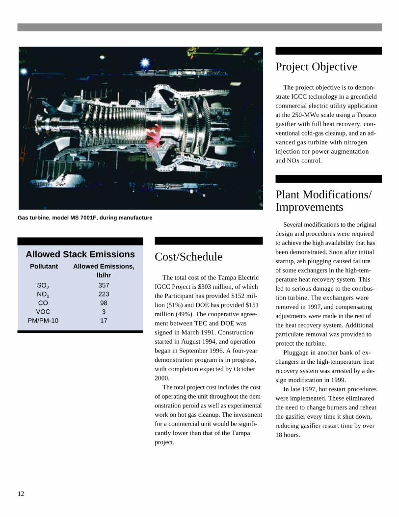
Initially, there were problems with the
gasifier which is 50% larger than any pre-vious Texaco gasifier. Carbon conversion
in this larger gasifier was lower than ex-
pected, and refractory life has been identi-fied as a significant issue. Liner replacement
is expensive and requires considerable
down time. To achieve the target life oftwo years, the gasifier is being operated at
a lower temperature than design, which in
turn results in a further decrease in carbonconversion efficiency. This caused load re-
strictions due to capacity limitations in the
fines handling system. A slag crusher and aduplicate fines handling system installed in
1998 solved this problem.
Thermocouple replacement in the gas-ifier also presents a problem. Replacement
is relatively expensive. Thermocouple fail-
ure by shearing is attributed to expansionof dissimilar materials.
In early 1998, revised operating proce-
dures were developed to handle high shelltemperatures in the dome of the radiant
syngas cooler. This problem had caused
two extended outages.Numerous short forced outages occurred
in 1997 and 1998 due to erosion and corro-
sion in the process water and coal/waterslurry piping systems, pumps, and valves.
Various changes have virtually eliminated
these problems, and no such outages oc-curred in 1999. Some of the corrective
actions taken to solve operating and main-
tenance problems in this project have re-sulted in patent applications.
Gas Turbine 192 MWeSteam Turbine 121 MWe
Gross 313 MWe
Auxiliaries Power Use 63 MWe
Net Power Output 250 MWe
Power Output
The Texaco gasifier is in the largest structure, which also contains the radiant syngascooler. The hot gas cleanup system is installed in the smaller of the two large structures.In the foreground is the air separation unit.
14
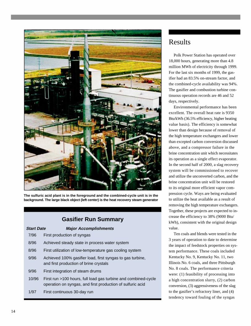
The sulfuric acid plant is in the foreground and the combined-cycle unit is in thebackground. The large black object (left center) is the heat recovery steam generator
Gasifier Run Summary
7/96 First production of syngas
8/96 Achieved steady state in process water system
8/96 First utilization of low-temperature gas cooling system
9/96 Achieved 100% gasifier load, first syngas to gas turbine,and first production of brine crystals
9/96 First integration of steam drums
10/96 First run >100 hours, full load gas turbine and combined-cycleoperation on syngas, and first production of sulfuric acid
1/97 First continuous 30-day run
Start Date Major Accomplishments
Results
Polk Power Station has operated over18,000 hours, generating more than 4.8
million MWh of electricity through 1999.
For the last six months of 1999, the gas-ifier had an 83.5% on-stream factor, and
the combined-cycle availability was 94%.
The gasifier and combustion turbine con-tinuous operation records are 46 and 52
days, respectively.
Environmental performance has beenexcellent. The overall heat rate is 9350
Btu/kWh (36.5% efficiency, higher heating
value basis). The efficiency is somewhatlower than design because of removal of
the high temperature exchangers and lower
than excepted carbon conversion discussedabove, and a compressor failure in the
brine concentration unit which necessitates
its operation as a single effect evaporator.In the second half of 2000, a slag recovery
system will be commissioned to recover
and utilize the unconverted carbon, and thebrine concentration unit will be restored
to its original more efficient vapor com-
pression cycle. Ways are being evaluatedto utilize the heat available as a result of
removing the high temperature exchangers.
Together, these projects are expected to in-crease the efficiency to 38% (9000 Btu/
kWh), consistent with the original design
value.Ten coals and blends were tested in the
3 years of operation to date to determine
the impact of feedstock properties on sys-tem performance. These coals included
Kentucky No. 9, Kentucky No. 11, two
Illinois No. 6 coals, and three PittsburghNo. 8 coals. The performance criteria
were: (1) feasibility of processing into
a high concentration slurry, (2) carbonconversion, (3) aggressiveness of the slag
to the gasifier’s refractory liner, and (4)
tendency toward fouling of the syngas
15
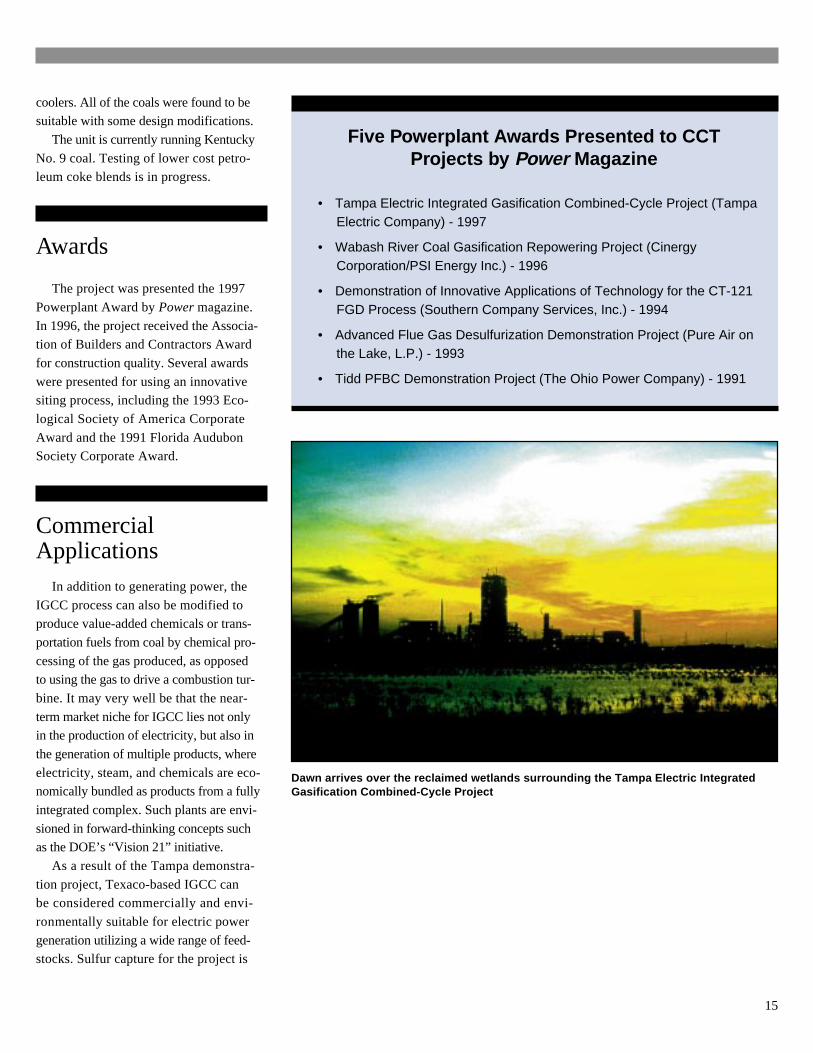
Dawn arrives over the reclaimed wetlands surrounding the Tampa Electric IntegratedGasification Combined-Cycle Project
Five Powerplant Awards Presented to CCTProjects by Power Magazine
• Tampa Electric Integrated Gasification Combined-Cycle Project (TampaElectric Company) - 1997
• Wabash River Coal Gasification Repowering Project (CinergyCorporation/PSI Energy Inc.) - 1996
• Demonstration of Innovative Applications of Technology for the CT-121FGD Process (Southern Company Services, Inc.) - 1994
• Advanced Flue Gas Desulfurization Demonstration Project (Pure Air onthe Lake, L.P.) - 1993
• Tidd PFBC Demonstration Project (The Ohio Power Company) - 1991
coolers. All of the coals were found to besuitable with some design modifications.
The unit is currently running Kentucky
No. 9 coal. Testing of lower cost petro-leum coke blends is in progress.
Awards
The project was presented the 1997
Powerplant Award by Power magazine.
In 1996, the project received the Associa-tion of Builders and Contractors Award
for construction quality. Several awards
were presented for using an innovativesiting process, including the 1993 Eco-
logical Society of America Corporate
Award and the 1991 Florida AudubonSociety Corporate Award.
CommercialApplications
In addition to generating power, the
IGCC process can also be modified toproduce value-added chemicals or trans-
portation fuels from coal by chemical pro-
cessing of the gas produced, as opposedto using the gas to drive a combustion tur-
bine. It may very well be that the near-
term market niche for IGCC lies not onlyin the production of electricity, but also in
the generation of multiple products, where
electricity, steam, and chemicals are eco-nomically bundled as products from a fully
integrated complex. Such plants are envi-
sioned in forward-thinking concepts suchas the DOE’s “Vision 21” initiative.
As a result of the Tampa demonstra-
tion project, Texaco-based IGCC canbe considered commercially and envi-
ronmentally suitable for electric power
generation utilizing a wide range of feed-stocks. Sulfur capture for the project is
16
Coal Gasification
Coal gasification has beenused for many years. Primitivecoal gasification provided towngas worldwide more than 100years ago, and a gasificationindustry produced coal-basedtransportation fuels for Germanyin World War II.
Today, coal gasification isseeing increasing use. In theU.S., a Texaco gasifier is utilizedin commercial operation at theTennessee Eastman chemicalplant in Kingsport, Tennesseeto produce synthesis gas for pro-duction of methanol. The DakotaGasification plant in North Dakotaproduces substitute natural gasand chemicals based on an ad-vanced World War II gasificationtechnology.
Overseas, a major chemicaland transportation fuel industryexists in The Republic of SouthAfrica, mostly based upon ad-vancements of World War II gasifi-cation technologies. An IGCCpower plant is in operation in TheNetherlands. There are severalGerman gasifiers that are com-mercially available. Texaco gasifi-ers are in commercial operation,or planned operation, in thePeople’s Republic of Chinaand other nations.
Advanced gasification and IGCCtechnology development began inthe U.S. in the 1960s, the stimuli be-ing the desire for (1) development ofcoal-based replacements for naturalgas and oil due to shortages andprice increases; and (2) more effi-cient, clean coal-based powerplants. Modern IGCC technology isa response of U.S. government andindustry to these needs. Such sys-tems use advanced pressurized coalgasifiers to produce a fuel for gasturbine-based electric power gen-eration; the hot-gas turbine exhaustproduces steam to generate addi-tional electricity.
The first commercial scale useof a gasifier in a U.S. IGCC projectwas the Cool Water Project in Cali-fornia, which was based upon theTexaco coal gasification technology.The Cool Water Project, which re-ceived major support from the U.S.Synthetic Fuels Corporation, South-ern California Edison Company,EPRI (formerly the Electric PowerResearch Institute), and others, wasinstrumental in proving the feasibilityof IGCC, including their exceptionalenvironmental performance.
Gas turbines for power generationhave been one of the consequencesof jet aircraft engine development.Initially utilized for peaking purposes
by utilities, their reliability, efficiencyand output have improved to the ex-tent that they now also provide inter-mediate and baseload electric power.It is projected that gas turbines andIGCCs will contribute significantly tofuture increases in power generation.
Today’s IGCC is efficient becauseof major improvements that havetaken place in coal gasification andgas turbine technologies, and a highdegree of system integration thatefficiently recovers and uses wasteheat.
Gas cleanup in an IGCC powerplant is relatively inexpensive com-pared with flue gas cleanup in con-ventional coal-fired steam powerplants. Smaller equipment is re-quired because a much smaller vol-ume of gas is cleaned. This resultsfrom the fact that contaminants areremoved from the pressurized fuelgas before combustion. In contrast,the volume of flue gas from a coal-steam power plant is 40-60 timesgreater because the flue gas iscleaned at atmospheric pressure.
Atmospheric emissions are verylow due to proven technologies forhighly effective removal of sulfur andother contaminants from the syngas.Advancements being demonstratedin the CCT program are expectedto result in still better efficiencies.
17
Typical Coal Analysis(Pittsburgh No. 8 Seam)
Ultimate Analysis, As-Received, wt%
Moisture 4.74Carbon 73.76
Hydrogen 4.72Nitrogen 1.39Chlorine 0.10Sulfur 2.45Ash 7.88
Oxygen 4.96Total 100.0
Higher Heating Value 13,290 Btu/lb
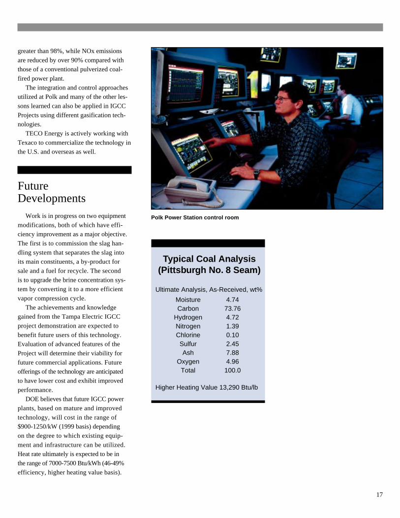
Polk Power Station control room
greater than 98%, while NOx emissions
are reduced by over 90% compared withthose of a conventional pulverized coal-
fired power plant.
The integration and control approachesutilized at Polk and many of the other les-
sons learned can also be applied in IGCC
Projects using different gasification tech-nologies.
TECO Energy is actively working with
Texaco to commercialize the technology inthe U.S. and overseas as well.
FutureDevelopments
Work is in progress on two equipment
modifications, both of which have effi-ciency improvement as a major objective.
The first is to commission the slag han-
dling system that separates the slag intoits main constituents, a by-product for
sale and a fuel for recycle. The second
is to upgrade the brine concentration sys-tem by converting it to a more efficient
vapor compression cycle.
The achievements and knowledgegained from the Tampa Electric IGCC
project demonstration are expected to
benefit future users of this technology.Evaluation of advanced features of the
Project will determine their viability for
future commercial applications. Futureofferings of the technology are anticipated
to have lower cost and exhibit improved
performance.DOE believes that future IGCC power
plants, based on mature and improved
technology, will cost in the range of$900-1250/kW (1999 basis) depending
on the degree to which existing equip-
ment and infrastructure can be utilized.Heat rate ultimately is expected to be in
the range of 7000-7500 Btu/kWh (46-49%
efficiency, higher heating value basis).
18
Composition ofCleaned Syngas
Constituent Volume %
Carbon monoxide 42.7Hydrogen 38.3Carbon dioxide 14.4Methane 0.1Water 0.3Nitrogen 3.3Argon 0.9Hydrogen sulfide 200 ppmvCarbonyl sulfide 10 ppmvAmmonia 0.0 ppmv
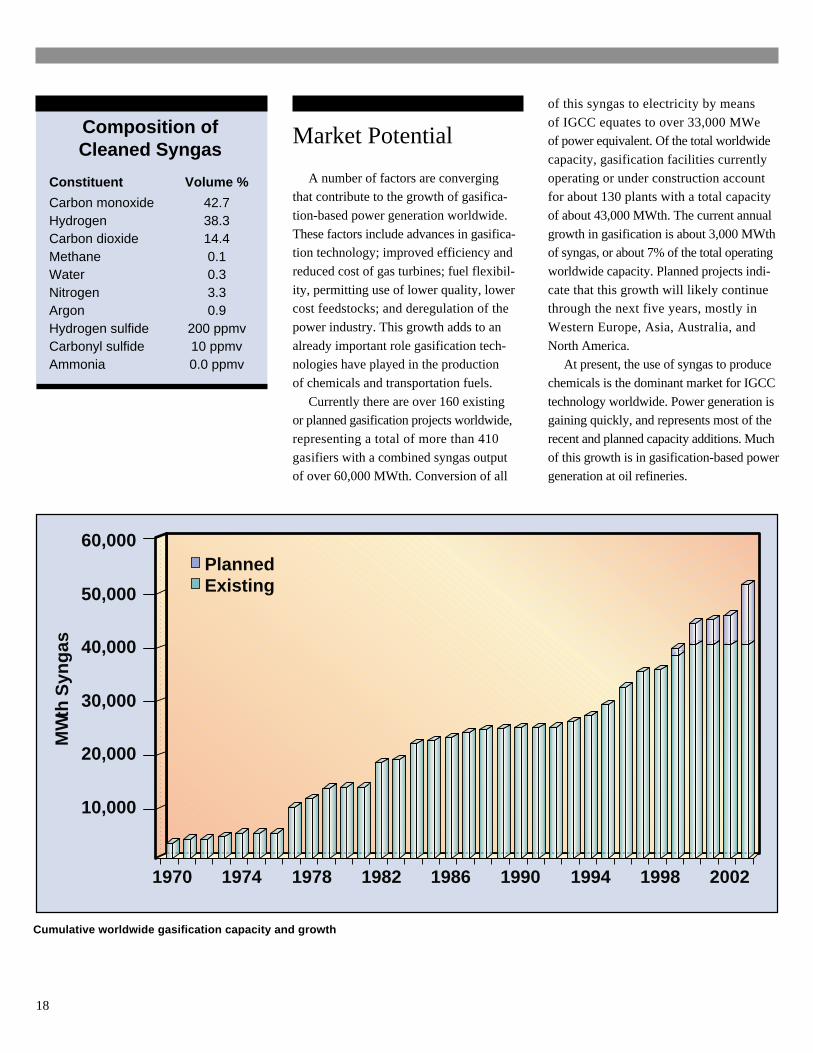
Cumulative worldwide gasification capacity and growth
1970 1974 1978 1982 1986 1990 1994 1998 2002
MW
th S
yng
as
10,000
20,000
30,000
40,000
50,000
60,000PlannedExisting
Market Potential
A number of factors are convergingthat contribute to the growth of gasifica-
tion-based power generation worldwide.
These factors include advances in gasifica-tion technology; improved efficiency and
reduced cost of gas turbines; fuel flexibil-
ity, permitting use of lower quality, lowercost feedstocks; and deregulation of the
power industry. This growth adds to an
already important role gasification tech-nologies have played in the production
of chemicals and transportation fuels.
Currently there are over 160 existingor planned gasification projects worldwide,
representing a total of more than 410
gasifiers with a combined syngas outputof over 60,000 MWth. Conversion of all
of this syngas to electricity by means
of IGCC equates to over 33,000 MWeof power equivalent. Of the total worldwide
capacity, gasification facilities currently
operating or under construction accountfor about 130 plants with a total capacity
of about 43,000 MWth. The current annual
growth in gasification is about 3,000 MWthof syngas, or about 7% of the total operating
worldwide capacity. Planned projects indi-
cate that this growth will likely continuethrough the next five years, mostly in
Western Europe, Asia, Australia, and
North America.At present, the use of syngas to produce
chemicals is the dominant market for IGCC
technology worldwide. Power generation isgaining quickly, and represents most of the
recent and planned capacity additions. Much
of this growth is in gasification-based powergeneration at oil refineries.
19
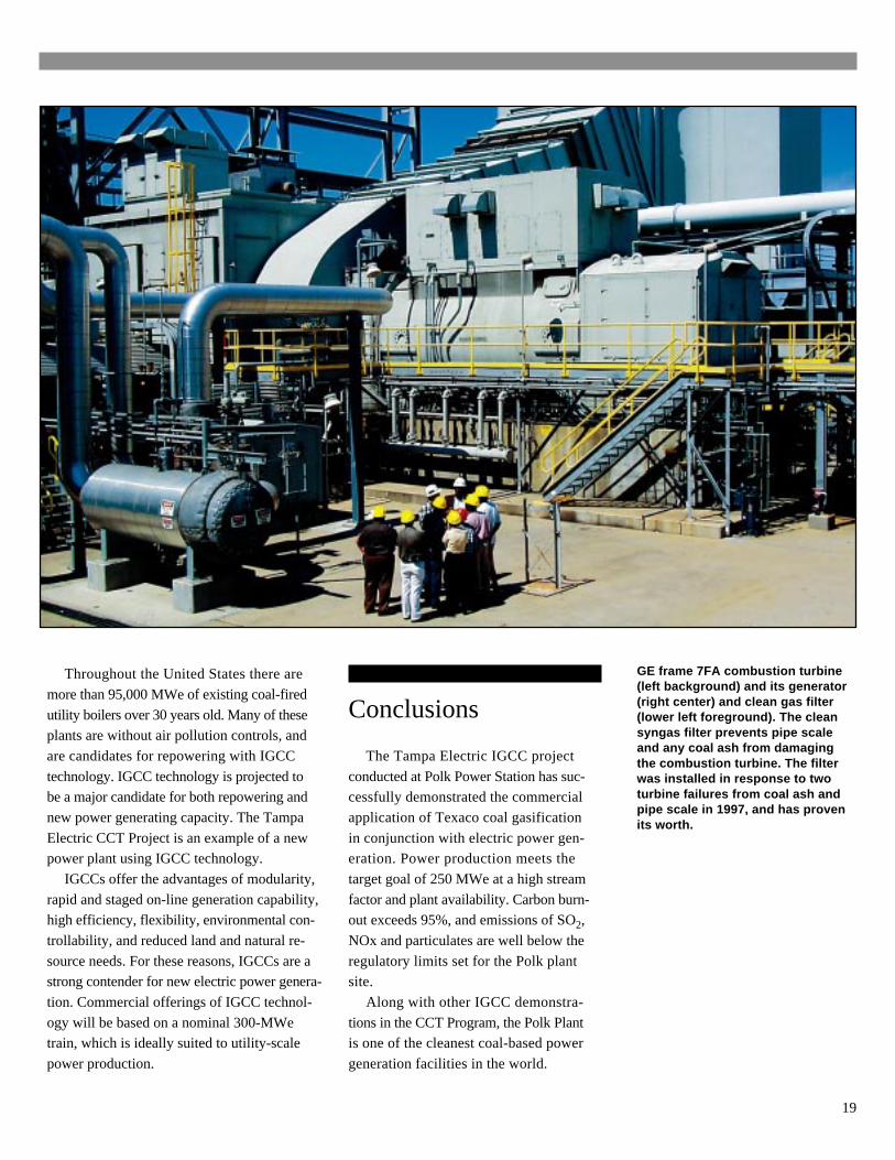
GE frame 7FA combustion turbine(left background) and its generator(right center) and clean gas filter(lower left foreground). The cleansyngas filter prevents pipe scaleand any coal ash from damagingthe combustion turbine. The filterwas installed in response to twoturbine failures from coal ash andpipe scale in 1997, and has provenits worth.
Conclusions
The Tampa Electric IGCC project
conducted at Polk Power Station has suc-cessfully demonstrated the commercial
application of Texaco coal gasification
in conjunction with electric power gen-eration. Power production meets the
target goal of 250 MWe at a high stream
factor and plant availability. Carbon burn-out exceeds 95%, and emissions of SO2,
NOx and particulates are well below the
regulatory limits set for the Polk plantsite.
Along with other IGCC demonstra-
tions in the CCT Program, the Polk Plantis one of the cleanest coal-based power
generation facilities in the world.
Throughout the United States there are
more than 95,000 MWe of existing coal-fired
utility boilers over 30 years old. Many of theseplants are without air pollution controls, and
are candidates for repowering with IGCC
technology. IGCC technology is projected tobe a major candidate for both repowering and
new power generating capacity. The Tampa
Electric CCT Project is an example of a newpower plant using IGCC technology.
IGCCs offer the advantages of modularity,
rapid and staged on-line generation capability,high efficiency, flexibility, environmental con-
trollability, and reduced land and natural re-
source needs. For these reasons, IGCCs are astrong contender for new electric power genera-
tion. Commercial offerings of IGCC technol-
ogy will be based on a nominal 300-MWetrain, which is ideally suited to utility-scale
power production.
20
Bibliography
S.D. Jenkins, “Status of Tampa ElectricCompany IGCC Project,” First Annual
Clean Coal Technology Conference
(Cleveland OH), November 1992.
D.E. Pless, “Tampa Electric Company:
Integrated Gasification Combined-CycleSystem,” Second Annual Clean Coal Tech-
nology Conference (Atlanta GA), Septem-
ber 1993.
C.R. Black, “Polk Status Update,” Twelfth
EPRI Conference on Coal Gasification
Power Plants (San Francisco CA), October
1993.
S.D. Jenkins, “Polk Status Update,” Eco-
nomics of Emerging Clean Coal Technolo-
gies III, February 1994.
U.S. Environmental Protection Agency,
“Final Environmental Impact Statement,Tampa Electric Company-Polk Power Sta-
tion,” EPA 904/9-94-002(b), June 1994.
Tampa Electric Company, “Tampa Electric
Company Polk Power Station Unit No. 1,”
Preliminary Public Design Report, June1994.
D.E. Pless, “Polk Status Update,” Third
Annual Clean Coal Technology Confer-
ence (Chicago IL), September 1994.
S.D. Jenkins, “Polk Power Station Syngas
Cooling System,” Eleventh Worldwide
Texaco Gasification Licensee Symposium
(White Plains NY), October 1994.
P.A. Pritchard and G.J. Starheim, “TurbineDevelopments for IGCC Applications, Sta-
tus Update,” Thirteenth EPRI Conference
on Coal Gasification Power Plants (SanFrancisco CA), October 1994.
D.E. Pless, “Status Update, Polk PowerStation” Fourth Annual Clean Coal Tech-
nology Conference (Denver CO), Septem-
ber 1995.
S.D. Jenkins, “Tampa Electric Company
Polk Power Station IGCC Project,” Twelfth
Annual International Pittsburgh Coal Con-
ference (Pittsburgh PA), September 1995.
C.R. Black, “Tampa Electric Company’s
Polk Power Station Construction Update,”
EPRI Conference on New Power Genera-
tion Technology (San Francisco CA), Oc-
tober 1995.
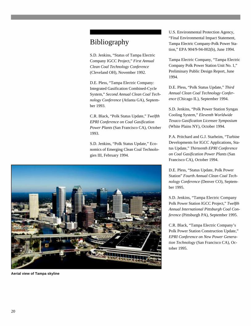
Aerial view of Tampa skyline
21
“Startup of Large-Scale Projects Casts
Spotlight on IGCC,” Power, June 1996.
“Compare Air-Blown to Oxygen-Blown
Gasification,” Power, June 1996.
Topical Report No. 6, “The Tampa Electric
Integrated Gasification Combined-CycleProject,” U.S. DOE, October 1996.
“Clean Coal Technology Breakthroughsare Expected to Keep Coal a Viable Op-
tion,” Power Engineering, May 1997.
“1997 Powerplant Award - Polk Power
Station,” Power, June 1997.
“IGCC Technology Offers Fuel Diversity,
Coproduction for Competitive Genera-
tion,” Power Engineering, September1997.
“IGCC Offers Diversity for CompetitiveGeneration,” Power Engineering, Novem-
ber 1997.
J.E. McDaniel and C.A. Shelnut, “Tampa
Electric Company Polk Power Station
IGCC Project -- Project Status,” Sixth
Clean Coal Technology Conference
(Reno NV), May 1998.
“Preparing for the Millennium,” Power
Engineering, November 1998.
J.E. McDaniel and C.A. Shelnut, “Tampa
Electric Company Polk Power Station
IGCC Project -- Project Status,” Seventh
Clean Coal Technology Conference
(Knoxville TN), June 1999.
J.E. McDaniel and C.A. Shelnut, “Tampa
Electric Company Polk Power StationIGCC Project -- Project Status,” 1999
Gasification Technologies Conference
(San Francisco CA), October 1999.
“IGCC Gathers Pace,” Power Engineering,
November 1999.
U.S. Department of Energy, Energy Infor-
mation Administration, “Annual EnergyOutlook 2000 with Projections to 2020,”
December 1999.
“Cleaning Up on Economics,” Power
Engineering, December 1999.
U.S. Department of Energy and the Gasifi-
cation Technologies Council, “Gasifica-
tion–Worldwide Use and Acceptance,”
January 2000
“Merchant Power Projects Push for Com-petitive Edge,” Power, pp. 32-39, January/
February 2000.
U.S. Department of Energy, Clean Coal
Technology Demonstration Program–
Program Update, April 2000.
22
The Clean Coal Technology (CCT)Program of the U.S. Department of En-ergy (DOE), a model of governmentand industry cooperation, supportsDOE’s mission to foster a secure andreliable energy supply system in theUnited States that is environmentallyand economically sustainable. TheCCT Program represents an invest-ment of over $5 billion in advancedcoal-based technology, with industryand state governments providing asignificant share —66% —of the fund-ing. With 26 of the 38 projects havingcompleted operations, the CCT Pro-gram has resulted in clean coal tech-nologies that are capable of meetingexisting and emerging environmentalregulations and competing in a deregu-lated electric power marketplace.
The CCT Program provides a port-folio of process options that will en-able continued use of the UnitedStates’ huge economically recover-able coal reserves (over 270 yearsat current consumption rates) to meetthe nation’s energy needs economi-cally and in an environmentally soundmanner.
As the new millennium begins,many of the clean coal technologieshave reached commercial status. In-dustry stands ready to employ themboth domestically and internationallyto respond to the energy and environ-mental demands of the 21st century.For existing power plants, there arecost-effective environmental controldevices to minimize emissions of sul-fur dioxide (SO2), nitrogen oxides(NOx), and particulate matter (PM).The CCT Program has taken a pollu-tion prevention approach as well,providing technologies that removepollutants or their precursors fromcoal before combustion.
The Clean Coal Technology Program
Also ready is a new generationof technologies that can produce elec-tricity and other commodities, such assteam and synthesis gas, at high effi-ciencies consistent with concernsabout global climate change.
Additionally, new technologieshave been introduced into majorcoal-using industries, such as steelproduction, to enhance environmen-tal performance. Thanks in part tothe CCT Program, coal—abundant,secure, and economical throughoutmuch of the world—can continue inits role as a key component in sup-plying U.S. and world energy needs.
The CCT Program also has globalimportance in providing clean andefficient coal-based technologiesto a burgeoning energy market indeveloping countries. World energyconsumption is expected to increase63% by 2020, and coal, the predomi-nant indigenous fuel in much of theworld, will be the fuel of choice forelectricity production. CCT pro-cesses offer a cost-effective meansto mitigate potential environmentalproblems associated with this un-precedented energy growth.
Most of the CCT demonstrationshave been conducted at commercialscale, in actual user environments,and under circumstances typical ofcommercial operations. Each projectaddresses one of the following fourmarket sectors:
• Advanced electric powergeneration
• Environmental control devices• Coal processing for clean fuels• Industrial applicationsThe project described in this Topi-
cal Report was developed under thecategory of Advanced Electric PowerGeneration.
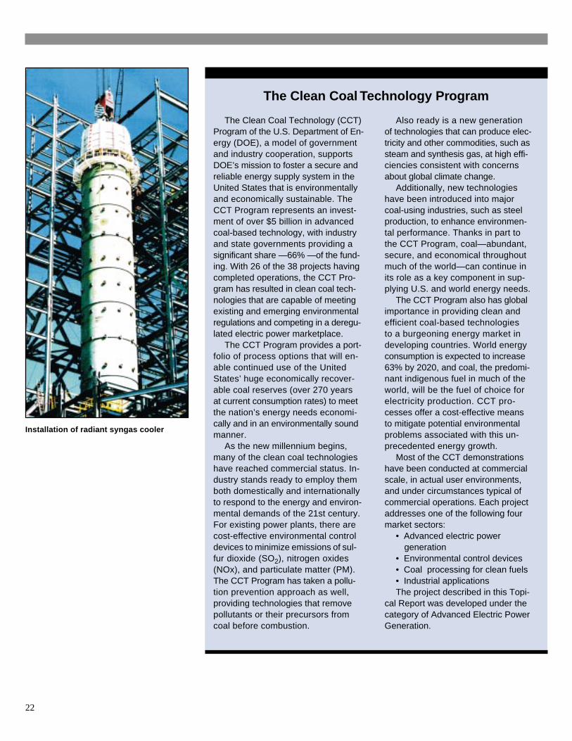
Installation of radiant syngas cooler
23
Robert C. PorterDirector, Office of CommunicationU.S. Department of Energy, FE-51000 Independence Ave SWWashington DC 20585(202) 586-6503(202) 586-5146 [email protected]
Otis MillsPublic Information OfficeU.S. Department of EnergyNational Energy Technology
LaboratoryP.O. Box 10940Pittsburgh PA 15236-0940(412) 386-5890(412) 386-6195 [email protected]
Participant Contact
Mark HornickGeneral Manager - Polk Power StationTampa Electric CompanyP.O. Box 111Tampa FL 33601-0111(813) 228-1111 x 39988(863) 428-5927 [email protected]
U.S. Department of Energy Contacts
Victor DerDirector, Office of Power SystemsU.S. Department of Energy, FE-24Germantown MD 20874-1290(301) 903-2700(301) 903-2713 [email protected]
James U. WattsProject ManagerNational Energy Technology
LaboratoryP.O. Box 10940Pittsburgh PA 15236-0940(412) 386-5991(412) 386-4775 [email protected]
Contacts for CCT Projectsand U.S. DOE CCT Program
This report is available on the Internetat U.S. DOE, Office of Fossil Energy’s home page: www.fe.doe.gov
and on the Clean Coal Technology Compendium home page:www.lanl.doe.gov/projects/cctc
To Receive AdditionalInformation
To be placed on the Departmentof Energy’s distribution list for futureinformation on the Clean Coal Tech-nology Program, the demonstrationprojects it is financing, or other FossilEnergy Programs, please contact:

24
List of Acronyms and Abbreviations
Btu. ............................................................. British thermal unit
CAAA ......................................................... Clean Air Act Amendments of 1990
CCT ............................................................ Clean Coal Technology
CO............................................................... carbon monoxide
CO2 ............................................................. carbon dioxide
COS ............................................................ carbonyl sulfide
DOE ............................................................ U.S. Department of Energy
EPA ............................................................ U.S. Environmental Protection Agency
HCl ............................................................. hydrogen chloride
HRSG ......................................................... heat recovery steam generator
H2S ............................................................. hydrogen sulfide
H2SO4 ......................................................... sulfuric acid
IGCC .......................................................... integrated gasification combined-cycle
kV ............................................................... kilovolt
kWh ............................................................ kilowatt hour
MWe ........................................................... megawatts of electric power
MWth .......................................................... megawatts of thermal power (1 MWth = 3.413x10⁶ Btu/hr)
NETL .......................................................... National Energy Technology Laboratory
NOx ............................................................ nitrogen oxides
O2 ................................................................ oxygen
PM .............................................................. particulate matter
ppmv ........................................................... parts per million by volume
psig ............................................................. pressure, pounds per square inch (gauge)
SO2 ............................................................. sulfur dioxide
SO3 ............................................................. sulfur trioxide
syngas ......................................................... synthesis gas
TEC ............................................................ Tampa Electric Company
TPS ............................................................. TECO Power Services Corporation
VOC ............................................................ volatile organic compounds
wt % ............................................................ percent by weight