tank operations contractor high-efficiency particulate air ...€¦ · the tank operations...
TRANSCRIPT

A-6002-767 (REV. 3)
(DRAFT) RPP-RPT-54544, Rev.1
Tank Operations Contractor High-Efficiency Particulate Air (HEPA) Filter Management Plan S. Khabir Washington River Protection Solutions, LLC Richland, WA 99352 U.S. Department of Energy Contract DE-AC27-08RV14800 EDT/ECN: UC: Cost Center: 2KA00 Charge Code: B&R Code: Total Pages: Key Words: HEPA, Filters, Management Plan, Service Life Abstract: The Hanford Tank Operations Contractor (TOC) is responsible to operate and maintain Double-Shell Tank (DST) and Single-Shell Tank (SST) farms, 242-A Evaporator Building and 222-S Laboratory facilities in 200 East and 200 West area of the Hanford Site. This management plan reviews HEPA filter service discussed in various national consensuses nuclear industry standards/guidelines. It reviews shelf and operating life of installed HEPA filters and provides recommendations for replacement. TRADEMARK DISCLAIMER. Reference herein to any specific commercial product, process, or service by trade name, trademark, manufacturer, or otherwise, does not necessarily constitute or imply its endorsement, recommendation, or favoring by the United States Government or any agency thereof or its contractors or subcontractors.
Release Approval Date Release Stamp
Approved For Public Release

RPP-RPT-54544 Revision 1 (DRAFT)
A-6002-767 (REV. 3)
Tank Operations Contractor High-Efficiency Particulate Air (HEPA) Filter Management Plan Prepared by S. Khabir Engineering Program & Standards TOC HVAC Systems Discipline Lead Washington River Protection Solutions, LLC Date Published February 2015
Prepared for the U.S. Department of Energy Office of River Protection Contract No. DE-AC27-08RV14800
RPP-RPT-54544, Rev. 1 (DRAFT)
i
EXECUTIVE SUMMARY The Tank Operations Contractor (TOC) is responsible to operate and maintain the Double-Shell Tank Farm, Single-Shell Tank Farm, 242-A Evaporator, and 222-S Laboratory facilities in the 200 East and 200 West Areas of the Hanford Site. The TOC ventilation system High Efficiency Particulate Air (HEPA) filters protect the workers, the public, and the environment from an exposure to airborne particulates from the liquid radioactive waste storage tanks prior to discharging the air to the atmosphere. The TOC HEPA filter management plan describes the different categories of HEPA filters within the TOC facilities and establishes a program for HEPA filter management depending on the category of HEPA filter and factors affecting filter’s operating life. Some HEPA filters are regulated by the Washington State Department of Health (WDOH) and are categorized as Potential Impact Category (PIC) 1 through 4 based on the source term potential to emit. The HEPA filters not regulated by WDOH are included in this management plan as “Best Management Practice” filters for completeness and replacement associated cost should the existing performance based approach identify the need for a different change-out frequency. Some of the WDOH-regulated PIC-1 through PIC-4 HEPA filters are changed out on an automatic schedule or periodic frequency due to WDOH air permit license requirements. In other cases, HEPA filters are changed out because they fail performance testing and do not approach a time-based established limit change-out. The remaining subset of HEPA filters are changed out based on a time limit. The time-based change-out frequency program establishes a HEPA filter maximum service/total life of 20 years (maximum of 10 years shelf life and maximum of 10 years operating life) for the initial replacement frequency because the installation date of the HEPA filter is unknown. Once HEPA filters are replaced initially under a time-based change-out frequency, the subsequent replacement frequency filters (banks) approaching 10 years of operating life will be scheduled for replacement before 10 years of operating life expire. The TOC emission unit HEPA filters are procured, maintained, and operated in accordance with national consensus industry standards, best engineering practices and applicable codes utilizing a graded approach commensurate with the associated hazards in each facility. In order to address the backlog of filters requiring replacement, a priority list of WDOH-regulated PIC-1 through PIC-4 HEPA filters to be replaced during plan implementation has been developed and is found in Appendix A. In addition, the list in Appendix A provides a basis to develop a rough order of magnitude estimate for implementation of the program annually for the next 10 years and is not intended to be updated or maintained. Replacement priority is based on filter age and PIC category. An engineering evaluation of HEPA filter service/total life was completed for continuously-operated powered emission units used at the TOC. This evaluation reviewed operational history, failure rates, filter classifications, location, filter age, performance, storage and any potential exposure to moisture to develop a prioritized list for replacement of the HEPA filters (see Appendix A).

RPP-RPT-54544, Rev. 1 (DRAFT)
ii
TABLE OF CONTENTS
1.0 INTRODUCTION ...............................................................................................................1
1.1 PURPOSE ................................................................................................................1
1.2 SCOPE .....................................................................................................................1
1.3 APPLICABILITY ....................................................................................................1
1.4 IMPLEMENTATION ..............................................................................................2
2.0 DEFINITIONS .....................................................................................................................3
3.0 HIGH EFFICIENCY PARTICULATE AIR FILTER REQUIREMENTS .........................5
3.1 OVERVIEW ............................................................................................................5
3.2 HIGH EFFICIENCY PARTICULATE AIR FILTER PROCUREMENT ..............6 3.2.1 Requirements ...............................................................................................6 3.2.2 Basis .............................................................................................................6
3.3 PACKAGING, SHIPPING, AND STORAGE ........................................................7 3.3.1 Requirements ...............................................................................................7 3.3.2 Basis .............................................................................................................7
3.4 SHELF LIFE ............................................................................................................7 3.4.1 Requirements ...............................................................................................7 3.4.2 Basis .............................................................................................................7
3.5 SERVICE/TOTAL LIFE .........................................................................................8 3.5.1 Requirements ...............................................................................................8 3.5.2 Basis .............................................................................................................8
3.6 OPERATING LIFE .................................................................................................9 3.6.1 Requirements ...............................................................................................9 3.6.2 Basis .............................................................................................................9
3.7 MANUFACTURER IN–PLACE CHALLENGE TEST .......................................11 3.7.1 Requirements .............................................................................................11 3.7.2 Basis ...........................................................................................................12
3.8 MONITORING ......................................................................................................12 3.8.1 Environmental Parameters .........................................................................12 3.8.2 Monitoring Parameters/Limits ...................................................................13
4.0 IMPLEMENTATION REQUIREMENTS ........................................................................14
4.1 MANAGEMENT OF HIGH EFFICIENCY PARTICULATE AIR FILTERS IMPLEMENTATION ...........................................................................14
RPP-RPT-54544, Rev. 1 (DRAFT)
iii
4.2 HIGH EFFICIENCY PARTICULATE AIR FILTER STORAGE AND INVENTORY TRACKING...................................................................................14
4.3 HIGH EFFICIENCY PARTICULATE AIR FILTER INSTALLATION AND REPLACEMENT TRACKING ...................................................................14
4.4 PLANNING AND SCHEDULING .......................................................................15
5.0 RECOMMENDATIONS ...................................................................................................16
6.0 REFERENCES ..................................................................................................................16
APPENDIX A – FACILITY FILTERS EVALUATION ........................................................... A-1
LIST OF TABLES Table 1-1. Tank Operations Contractor High Efficiency Particulate Air Filter Category and Locations. ................................................................................................................................. 2
Table 4-1. Tank Operations Contractor High Efficiency Particulate Air Filter Service Life. ................................................................................................ Error! Bookmark not defined. Table A-1. Tank Farm Filter Replacement Priority List................................................................ 4
Table A-2. 222-S Laboratory Filter Replacement Priority List. .................................................... 6
Table A-3. List of 242-A Evaporator Building High Efficiency Particulate Air Filter Installations. .................................................................................................................................... 6
Table A-4. List of Tank Operations Contractor Best Management Practice High Efficiency Particulate Air Filters. ................................................................................................... 7
Table A-5. Rough Order of Magnitude Estimate to Replace High Efficiency Particulate Air Filters. ..................................................................................................................................... 15
Table A-6. Facility Rough Order of Magnitude Estimate to Replace High Efficiency Particulate Air Filters. ................................................................................................................... 15
LIST OF FIGURES Figure A-1. Guidance for Evaluating High Efficiency Particulate Air Filter Shelf and
Operating Life. ....................................................................................................... A-3

RPP-RPT-54544, Rev. 1 (DRAFT)
iv
LIST OF TERMS Abbreviations and Acronyms
ACGIH American Conference of Governmental Industrial Hygienists
ALARA As Low as Reasonably Achievable
ANSI American National Standards Institute
ASHRAE American Society of Heating, Refrigeration, and Air Conditioning Engineers
ASME American Society of Mechanical Engineers
BMP Best Management Practice
DNFSB Defense Nuclear Facilities Safety Board
DOE U.S. Department of Energy
DP differential pressure
DST Double-Shell Tank
EAM Enterprise Asset Management
FTF Filter Test Facility
GS General Service
HEPA High Efficiency Particulate Air
PIC Potential Impact Category
PMID Preventive Maintenance Identification
PTE Potential to Emit
QL Quality Level
RCW Revised Code of Washington SME Subject Matter Expert
SST Single-Shell Tank
TOC Tank Operations Contractor
WAC Washington Administrative Code WDOH Washington State Department of Health
WRPS Washington River Protection Solutions
w.g. Water Gauge
RPP-RPT-54544, Rev. 1 (DRAFT)
1
1.0 INTRODUCTION
The Tank Operations Contractor (TOC) at the Hanford Site is responsible to operate and maintain Double-Shell Tank (DST) and Single-Shell Tank (SST) Farms, 242-A Evaporator, and 222-S Laboratory facilities in 200 East and 200 West Areas of the Hanford Site. These ventilation systems have High Efficiency Particulate Air (HEPA) filters in the exhaust stream prior to air being discharged through stacks and released to the atmosphere. This is to protect the workers, the public and the environment from an exposure to airborne particulates from the liquid radioactive waste storage tanks. The HEPA filters are procured to “full quality” level as described in Washington River Protection Solutions (WRPS) standard TFC-ENG-STD-07, “Ventilation System Design Standard,” and are installed in the general service (GS) ventilation systems. Currently, there are no safety significant ventilation systems at TOC facilities. Some TOC HEPA filters are regulated by the Washington State Department of Health (WDOH) to meet the Washington Administrative Code (WAC) requirements found in WAC 246-247, “Radiation Protection – Air Emissions.” 1.1 PURPOSE
High Efficiency Particulate Air filters are a component of nuclear air and gas treatment systems that are subject to performance degradation from a number of factors including filter shelf time, operating time, and exposure to moisture in the processed air. The Defense Nuclear Facility Safety Board (DNFSB) Recommendation 2004-2, Active Confinement Systems identifies the need for the U.S. Department of Energy (DOE) contractors to establish a filter service life program per DOE-HDBK-1169-2003, Nuclear Air Cleaning Handbook, Section 3.2 and Appendix C. 1.2 SCOPE
This HEPA filter management plan applies to the DST and SST farms, 242-A Evaporator, and 222-S Laboratory emission units. The TOC HEPA filter management plan identifies programmatic requirements for management of HEPA filters. Because Revision 1 establishes a new, time-based change-out frequency program element as part of the TOC HEPA management plan, the plan also identifies a prioritized list for replacement of those filters currently operating beyond a service/total life (combined shelf and operating life) of 15 years, and then of 20 years. Once HEPA filters are replaced initially under a time-based change-out frequency, the subsequent replacement frequency filters (banks) approaching 10 years of operating life will be scheduled for replacement before 10 years of operating life expire. 1.3 APPLICABILITY
This document is applicable to any HEPA filter under TOC management and includes HEPA filters regulated by WDOH and those not regulated by WDOH (termed Best Management

RPP-RPT-54544, Rev. 1 (DRAFT)
2
Practice [BMP] in this document). Table 1-1 identified the category of HEPA filters maintained within the TOC.
Table 1-1. Tank Operations Contractor High Efficiency Particulate Air Filter Category and Locations.
High Efficiency Particulate Air Filter Category
Locations
Potential Impact Category 1 • Double-Shell Tank Primary Ventilation Systems • Most portable exhausters
Potential Impact Category 2 • 222-S Laboratory main exhaust
Potential Impact Category 3 • Most Double-Shell Tank Annulus exhausters • 242-A Evaporator
Potential Impact Category 4 • Single-Shell Tank breather filters • 222-S Laboratory sample gallery hood at the 219-S Tank
System • Miscellaneous tank breather filters • Portable temporary exhausters • High Efficiency Particulate Air vacuums
Best Management Practice • 222-S Laboratory hoods • Double-Shell Tank inlet vents
Note: For the complete list of HEPA filters regulated by WDOH, refer to RPP-16922, Environmental Specification Requirements. 1.4 IMPLEMENTATION
Upon publication of Revision 1, implementation of this plan will be used as a basis for future planning and scheduling of the TOC HEPA filter replacement program and development of implementing procedure(s). Initial implementation of this plan will be phased in over a period of time based on the recommended priority list included in Attachment A. The TOC Contract DE-AC27-08RV14800, Recovery Act – Tank Operations Contract, the contractual agreement with DOE, has a list of DOE directives, regulations, policies, and standards in Table J.2.8, “Directives, Regulations, Policies, and Standards.” In that table, DOE O 420.1B, Facility Safety is the applicable document listed for the facility safety. Section 4.b of DOE O 420.1B states:
“…All new construction, as a minimum, must comply with national consensus industry standards and the model building codes applicable for the state or region, supplemented in a graded manner with additional safety requirements for the associated hazards in the facility that are not addressed by the codes.”

RPP-RPT-54544, Rev. 1 (DRAFT)
3
The TOC complies with Revised Code of Washington (RCW) 70.94, “Washington Clean Air Act” requirements stated in WAC 246-247. The code states that the applicant (operator) will evaluate all available technologies that can reduce levels of radionuclide emissions to the environment. The emission unit design and construction must meet the technology standards if the potential to emit (PTE) exceeds 0.1 mrem/yr total effective dose to the maximum exposed individual per WAC 246-247-120, “Appendix B—BARCT Compliance Demonstration,” Appendix B.
2.0 DEFINITIONS
Age of Filters – The age of the HEPA filters is established from the date of manufacturer or the date stamped or marked on the filter. Should the date of manufacture be indeterminate, the date of the original certification at a DOE Filter Test Facility (FTF) shall be substituted for the date of manufacture. Best Management Practice – Filters whose performances are not derived from the regulations, are not identified or categorized in the facility permit applications, and are therefore included as recommended practices, not as requirements. Dry Ventilation System – Dry operation of a filter is defined as any operating condition or installation where the air relative humidity at the filter is maintained below 70%. Operating Mode – Tank farm operating mode is being defined for the first time for consistency with the HEPA filter management requirements. The tank farm operating mode depends on the facility mission and operational demands, as follows.
1. Normal active ventilation. Normal operating mode of the ventilation system to support day-to-day safe operations. There is no specific duration for the operating mode associated with maintaining the DST ventilation. This operating mode requires normal monitoring of the HEPA filter pressure and temperature during day-to-day operations.
2. Waste transfer activities. This operating mode does not have a defined duration and depends on the volume associated with waste transferred. The HEPA filters (including prefilter and first stage) differential pressure (DP) will increase due to the entrained particulates and amount of aerosol removed from the tank head space(s). This operating mode requires close monitoring of the prefilter and first stage HEPA filter DPs and affect the operating life of 10 years.
3. Mixer Pump Operation. This is a planned future operation mode for mixing tank waste contents prior to transferring waste to the Waste Treatment Plant. Prefilters and HEPA filters are expected to be replaced more frequently.

RPP-RPT-54544, Rev. 1 (DRAFT)
4
Note: Operating requirement technical basis for the ventilation systems, i.e., pressure, temperature, in-place leak test, and monitoring requirements and frequency are identified in the RPP-11413, Ventilation System In-Service Requirements. Potential Impact Category – Potential impact category (PIC) is defined as a ranking classification of potential radiological impact, based on factors such as PTE. A category applied to a radiological emission unit reflecting a graded approach for determining sampling and monitoring for the unit based on how much its PTE contributes to the Regulatory offsite dose limit. Referenced from American National Standards Institute (ANSI) N13.1-1999, Sampling and Monitoring Releases of Airborne Radioactive Substances from the Stacks and Ducts of Nuclear Facilities:
• PIC-1: PTE is > 5 mrem
• PIC-2: PTE is ≥ 0.1 mrem and ≤ 5 mrem
• PIC-3: PTE is ≥ 0.01 mrem and < 0.1 mrem
• PIC-4: PTE is ≤ 0.01 mrem Shelf Life – The time from when the HEPA filter is manufactured or date stamped by the manufacturer until it is placed into service. Operating Life – The time from when a HEPA filter is placed in service until it is removed from service. The time count begins as soon as a filter is placed in the filter housing regardless of whether it is in operation or standby operating mode. Factors such as humidity, DP, and radiation dose will affect the operating life. Service/Total Life – HEPA filter service/total life is defined as the time from the manufacturer date stamped or marked to the time at which the filter is removed from service. The term “service/total life” will only be used during the initial scheduling of HEPA change-out. Subsequent HEPA change-out frequencies will use operating life as a basis. Wet Ventilation System – Potential wet operation of a filter is defined as any filter operating condition or service installation where a filter may be exposed to liquid water or to high air humidity, as specified below.
1. Direct spray of nozzle-generated water droplets, at any temperature, and of any time duration.
2. Airborne droplets of condensed water (fog) at any temperature, and of any time duration.
3. Moist air flow at a relative humidity greater than 70%.
4. Gravity-driven surface water in the form of seepage or flood, that originates from any source.
Note: Wetting is not expected to occur in any of the powered TOC ventilation HEPA filtration systems due to installed design features such as demisters, heaters, and prefilters.
RPP-RPT-54544, Rev. 1 (DRAFT)
5
3.0 HIGH EFFICIENCY PARTICULATE AIR FILTER REQUIREMENTS
Requirements for HEPA filters are applicable to TOC HEPA filtered ventilation systems and facilities that protect personnel, the public, and the environment from exposure to hazardous aerosol particles. This section provides an overview of requirements, and then provides specific discussion of programmatic requirements. 3.1 OVERVIEW
Requirements for TOC HEPA filters are identified in Section 1.0 based on both Environmental and Engineering requirements. The documented safety analysis documents for DST, SST, 242-A Evaporator, and 222-S Laboratory facilities conclude that HEPA filters do not include any safety function and therefore do not impose requirements. For Environmental requirements, the Hanford Site Air Operating Permit, FF-01, Radioactive Air Emissions License for the Department of Energy Richland Office Hanford Site, issued by WDOH, meets the requirements for WAC 246-247. WRPS Environmental Protection maintains the FF-01 requirements in RPP-16922. Section 2 of RPP-16922 includes operational and preventive maintenance requirements. For Engineering requirements, the nuclear industry codes, and standards and guidelines such as those of the American Society of Mechanical Engineers (ASME), American Society of Heating, Refrigeration, and Air Conditioning Engineers (ASHRAE), American Conference of Governmental Industrial Hygienists, ANSI, Sheet Metal and Air Conditioning Contractors National Association, shall be used for ventilation system design and procurement along with standard industry practices. Based on sound engineering practices, these codes, standards and guidelines are the most applicable for design and procurement of ventilation systems and system components. These requirements are based on DOE 0 420.1B Change 1; ASME AG-1-2009, Code on Nuclear Air and Gas Treatment; ASME N509, Nuclear Power Plant Air-Cleaning Units and Components and N510, Testing of Nuclear Air Treatment Systems; guidelines in DOE-HDBK-1169-2003; and current ASHRAE standards and handbook. Installed active HEPA ventilation systems operating status including DP readings, air temperature, visual inspection, and aerosol test data shall be tracked in Enterprise Asset Management (EAM) for trending. Daily and weekly round field walk downs and monitoring are performed to identify any potential degrading conditions. Furthermore, HEPA filter shelf life and operating life are tracked in the EAM to ensure compliance with the implementing requirements. The applicable implementing codes and standards are:
• ASME/ANSI AG-1, Code on Nuclear Air and Gas Treatment,
• ASME N509, Nuclear Power Plant Air-Cleaning Units and Components,
• ASME N510, Testing of Nuclear Air Treatment Systems,

RPP-RPT-54544, Rev. 1 (DRAFT)
6
• ASME N511, In-Service Testing of Nuclear Air Treatment, Heating, Ventilating, and Air-Conditioning Systems,
• ASME NQA-1-2012, Quality Assurance Requirements for Nuclear Facility Applications,
• Title 40, Code of Federal Regulations, Part 60, “Standards of Performance for New Stationary Sources” (40 CFR 60) Appendix A, Methods 1, 1A, 2, 2A, 2C, 2D, 4, 5, and 17,
• ANSI/HPS N13.1-1999, Sampling and Monitoring Releases of Airborne Radioactive Substances from the Stacks and Ducts of Nuclear Facilities,
• ANSI N42.18, American National Standard Specification and Performance of On-Site Instrumentation for Continuously Monitoring Radioactivity in Effluents,
• ERDA 76-21, Nuclear Air Cleaning Handbook,
• ACGIH 2013, American Conference of Governmental Industrial Hygienists. 3.2 HIGH EFFICIENCY PARTICULATE AIR FILTER PROCUREMENT
3.2.1 Requirements
The HEPA filter procurement of material and subcontracted services shall include requirements necessary to ensure their compliance with ASME NQA-1-2012, Quality Assurance Requirements for Nuclear Facility Applications (hereinafter referred to as ASME NQA-1). 3.2.2 Basis
WAC 246-247 requires ASME AG-1 for compliant abatement technology. ASME AG-1, Division I, “General Requirements,” Section AA, “Common Article” requires that documents for procurement of material and subcontracted services shall include requirements necessary to ensure their compliance with ASME NQA-1. Procurement specifications for HEPA filtration systems are developed to meet the ASME AG-1 Article FC-I-3000 requirements. All HEPA filters at the Hanford Site are procured as “Full Quality” nuclear grade specifications per HNF-S-0477, Procurement Specification for Standard, Nuclear Grade, High Efficiency Particulate Air (HEPA) Filters (For Filters That Do Not Conform to ASME AG-1), HNF-S-0552, Procurement Specification for Standard, Nuclear Grade, High Efficiency Particulate Air (HEPA) Filters (For ASME AG-1 Section FC Compliant Filters), and RPP-SPEC-28675, AG-1, Section FK Special HEPA Filter (Radial and Axial) Procurement Specification. The HEPA filters used in the TOC nuclear facilities meet the ASME NQA-1 acceptable requirements of performance, design, construction, acceptance, and testing per ASME AG-1, Section FC, “HEPA Filters,” FC-4000, “Design”, and WAC 246-247.

RPP-RPT-54544, Rev. 1 (DRAFT)
7
3.3 PACKAGING, SHIPPING, AND STORAGE
3.3.1 Requirements
Per the ASME N509-2002 Section 6, packaging, shipping, receiving, storage, and handling shall meet the requirements of ASME NQA-1; ASME AG-1, Article AA-7000; and various specific ASME AG-1 Code sections. The HEPA filters should be stored in ASME NQA-1 Level B storage locations where they will not be exposed to dampness, excessive heat or cold or rapidly changing temperatures. The HEPA filters shall be packaged in corrugated cardboard cartons that conform to shipping regulations (ASME NQA-1, Requirement 13, “Handling, Storage and Shipping,” and Subpart 2.2). 3.3.2 Basis
ASME NQA-1 Requirement 13, “Handling, Storage and Shipping” under special requirements states that items requiring special protective environments such as pressure, temperature levels, or moisture content levels shall be specified, provided, and their existence verified. In addition, ASME NQA-1 Subpart 2.2 identifies Level B for items that are sensitive to environment conditions and requires measures for protection from the effects of temperature extremes, humidity and vapor, etc. The WRPS HEPA filters are stored in Level B warehouse environment up to a maximum of 10 years shelf life. These requirements are also identified in DOE-HDBK-1169-2003 and ASME AG-1, Article FC-7000. 3.4 SHELF LIFE
3.4.1 Requirements
Maximum shelf life of TOC HEPA filters shall be 10 years from the date of manufacture. The HEPA filters with gasket seals shall be inspected and durometer tested after 3 years in storage and prior to installation for service life. The HEPA filter with gel seals shall be inspected prior to installation. 3.4.2 Basis
Currently, there are no approved regulations or standards concerning the shelf life of HEPA filters. Based on the manufacturer recommendations, HEPA filter seals are inspected for damage, discontinuity, and elastomer gaskets (tested by the durometer in accordance with the Flanders inspection requirement) prior to use by the qualified Level 2 quality assurance inspector. Although Flanders recommends 3 years shelf life based on the blu-Jel®1 seal and elastomer gasket pliability, based on the review of the non-conformance database, TOC inspections of the HEPA filters prior to use have not revealed any blu-Jel® seal and elastomer gasket degradation for the past 10-year shelf life. Subsequent to pre-installation inspection of HEPA filters in the warehouse Level B, HEPA filters are in-service aerosol penetration tested
1 Flanders® and blu-Jel® are registered trademarks of Flanders Filters, Inc., Washington, North Carolina.

RPP-RPT-54544, Rev. 1 (DRAFT)
8
upon installation to ensure compliance with ASME N511-2007, Mandatory Appendix III, HEPA Filter Bank In-Place Leak Test Procedure. As previously stated in Section 3.1 of this document, HEPA filter age limits are based on highly variable process conditions and filters could fail at 7 to 13 years when dry. Because of the effective filter storage, inspection, monitoring programs, and identification of the influencing factors discussed earlier, and WRPS operating experiences, WRPS establishing the 10-year shelf life is an acceptable plan for meeting the emission unit’s compliance with WAC 246-247-120 Appendix B. 3.5 SERVICE/TOTAL LIFE
3.5.1 Requirements
The service/total life of a HEPA filter will only be used to prioritize replacing the backlog of HEPA filters. After the initial replacement, the installation date of the HEPA filter will be tracked using the 10-year operating life as the tracking criteria, and the service/total life will become obsolete. The user/owner of the facility shall incorporate written specifications on the service life of the HEPA filters for change-out criteria (DOE-HDBK-1169-2003 Chapter 3). WRPS has established a maximum operating life of 10 years for all filters. 3.5.2 Basis
Because the current WRPS program is not a time-based program, the installation date of a HEPA filter is labor-intensive to find. Using the service/total life is an efficient way to prioritize replacement of the HEPA filter backlog. DOE HDBK-1169-2003 Appendix C, “Determination of HEPA Filter Life,” provides recommended guidance for determining the acceptable service life of the HEPA filters. In addition, ASME AG-1-2012 Appendix FC-B (Draft April 2013) provides recommended guidelines for setting limits on the maximum allowable limit on service life for non-reinforced glass-fiber media under dry conditions, and adverse operating conditions involving potential and actual filter exposure to moisture are set no greater than 10 years. The TOC ventilation systems operating modes define the HEPA filter’s operating life. The TOC active ventilation systems design is comprised of prefilters and first stage and second stage filters to protect the workers, the public, and the environment from an exposure to hazardous materials from the liquid radioactive waste storage tanks prior to discharging air to the atmosphere. The service life of HEPA filters is extended by using less efficient filters as prefilters that selectively remove the largest particles and fibers from the incoming airstream. Lifetimes of HEPA filters can be increased by as much as four times with multiple prefilter changes during the interval between HEPA filter changes. The TOC operating experience has concluded that operating life of 10 years meets the DOE-HDBK-1169-2003 and ASME AG-1 non-mandatory guidance based on the current operating modes and the monitoring requirement as stated in Section 3.8 of this document. As the operating mode or the mission of the TOC ventilation systems change, the HEPA filter operating life will change as well. In general, HEPA filter systems tend to load up slowly until a pressure drop of 2 to 3 in. w.g. is reached and further operation will increase pressure drop much

RPP-RPT-54544, Rev. 1 (DRAFT)
9
faster. The HEPA filter change-out is normally initiated when the pressure drop approaches 3.0 in. w.g. The HEPA filter change-out and initiation levels may vary for specific filters based on filter loading rate, operational requirements, system configuration and maintenance scheduling. If under special operational conditions any filter cannot be replaced at the end of 10 years operating life, a technical evaluation will be performed for supporting the extension and will be submitted to DOE for concurrence. For determination of factors affecting shelf life, a flow chart is developed consistent with the DOE-HDBK-1169-2003 Appendix C (see Appendix A). The evaluation shall document filters were not exposed to events that could impact HEPA filters’ performance conditions and beyond the limits noted in sections (pressure drop 3.0 in. w.g., 200°F, and 70% relative humidity), and including trending the in-service challenge test. Filters are used until one of the following conditions trigger filter change-out:
• Filter DP exceeds preset limits (typically 5.9 in w.g. on first stage and 4.0 in w.g. on second stage filters)
• Aerosol test efficiency is less than 99.95%
• Dose rates reach or exceed as low as reasonably achievable (ALARA) limits for personnel exposure.
3.6 OPERATING LIFE
3.6.1 Requirements
• HEPA filter operating life is 10 years maximum from date installed, for all PIC-1 through PIC-4 emissions units and dry ventilation systems, unless as otherwise specified below;
• Radial passive breather filters shall be replaced on the frequency specified in the WDOH FF-01 license (e.g., every 365 days);
• G-1 breather filters shall be replaced every 3 to 5 years based on having condensation with potential for wicking;
• Filters exposed to an abnormal environment, i.e., liquid water, high air humidity that becomes saturated, shall be changed out as soon as possible;
• HEPA filter in-service aerosol penetration testing shall be performed annually or every 365 days, as specified in the WDOD FF-01 license for regulated HEPA filters.
3.6.2 Basis
High Efficiency Particulate Air filters are components of a nuclear air and gas treatment system that degrade with service. The user/owner of the facility shall incorporate written specifications on the operating life of the HEPA filters for change-out criteria in accordance with DOE-HDBK-1169-2003, Chapter 3, Section 3.1 and Appendix C. Defense Nuclear Facilities

RPP-RPT-54544, Rev. 1 (DRAFT)
10
Safety Board (DNFSB) Recommendation 2004-2 requires each DOE facility to establish a filter service life program using inputs from DOE-HDBK-1169-2003, Section 3.1 and ASME AG-1. The handbook requires the HEPA filter operating life and change-out be established based on the aging and upset environmental condition requirements. The HEPA filter shelf life and operating life must consider the environmental and operational parameters when exposed continuously. Currently, there are no approved regulations or standards concerning the operating life of HEPA filters. However, WRPS has established the operating life limit of 10 years from the date of installation based on the past and present process operating experiences, and monitoring program as outlined in Section 3.8 of this document. In addition, a review of other published documents such as UCRL-JC-115891, Rev. 1, Preliminary Studies to Determine the Shelf Life of HEPA Filters and “Aging of Filters In Service and In Storage” (ABSA 1996) has been considered for establishing the HEPA filter operating life limit. Both of these preliminary research published studies have concluded that tensile strength decreases with age, but the data used was not conclusive and sufficient enough to establish shelf or in service life. It is worthy of mentioning that the individual glass fibers undergo some degree of crystallization over time and become susceptible to breakage under the pressure pulsations associated with starting and stopping the system air flow, but there are no test results that confirm this belief. For this reason, it is recommended that HEPA filter operation be continuous. Furthermore, most filter failures identified in the studies were due to overpressure, pressure pulse, filter medium weak structure, lack of sufficient binder in the medium, sealant, and filter pack loose inside the filter frame. The factors that gradually change physical characteristics and performance of the filters over time are wear, embrittlement, corrosion, chemicals, and physical degradation processes. The filter components such as pleated filter medium, corrugated separators (aluminum), filter casing (304 SS), adhesive, and neoprene gaskets or gel seals are affected by these factors. As described in the DOE-HDBK-1169-2003 Appendix C, the age limits are based on highly variable process conditions and filters that could fail at 7 to 13 years when dry. Because of these influencing factors and industry experiences in failing HEPA filters in the past, recently published ASME AG-1 Non-Mandatory Appendix FC-B (DRAFT April 2013, pending approval), Guidelines for the Determination of HEPA Filter Service Life has provided recommended guidelines for setting limits on the maximum allowable service life of 10 years for dry conditions (FC-B-3100). The limits on service life were set based primarily upon data derived from observed decreases in tensile strength and water repellency of dry filter media samples with age and cumulative reductions in strength with repeated exposure to water. The non-mandatory appendix in subsection FC-B-3400 Responsibility states that “The Owner or designee of the facility should determine a filter service life for each filter application based upon relevant operating conditions specific to each individual air or gas treatment system.” The TOC ventilation systems are comprised of two ventilation trains (A train and B train) per tank farm designed to be operated simultaneously or independently. Currently, DST ventilations operate with one running train while the other is in standby. Each train consists of a demister, heater, prefilter, first and second stage filters, and exhaust fan. The second stage HEPA filters protect the system filtration integrity and provide added assurance should the prefilter and first stage filter monitoring parameters indicate any failure due to unforeseen conditions. Under such conditions, Operations stop the affected train and render the train inoperable for further
RPP-RPT-54544, Rev. 1 (DRAFT)
11
evaluation. In addition, each train runs on an average of 40% to 60% during normal modes of operations, and therefore the filter banks are not exposed to continuous operation as it is suggested for setting the maximum allowable service life of 10 years in DOE-HDBK-1169-2003 and ASME AG-1 non-mandatory Appendix FC-B. Should this service life requirement be imposed to WRPS mode of operation, the operating life perhaps could be extended to a roughly non-linear age limit of < 14 years. The HEPA filter operational experience obtained at Tank Farm facilities supports the operating life of 10 years due to the fact that the standby HEPA filter banks, including prefilters and first and second stage filters, experience a higher chance of failure due to exposure to entrained aerosol, pressure, and temperature when the system status changes from standby mode to the running mode. However, none of the ventilation system failures in the past have been caused by such failures. The WRPS ventilation systems monitoring program as stated in Section 3.8 of this document supports acceptability of the maximum of 10 years operating life. For determination of factors affecting operating life, a flow chart is developed consistent with the DOE-HDBK-1169-2003 Appendix C (see Appendix A). The TOC HEPA filter aerosol penetration testing of active ventilation systems is performed annually and meets the aerosol test efficiency of 99.97% to comply with the ASME N511-2007, Mandatory Appendix III, HEPA Filter Bank In-Place Leak Test Procedure. The radial HEPA filters that are installed on a passive ventilation system are replaced on the frequency specified in the WDOH FF-01 license (e.g., every 365 day) and are not aerosol tested. The G-1 filters will be replaced every 3 to 5 years based on having condensation with potential for wicking. 3.7 MANUFACTURER IN–PLACE CHALLENGE TEST
3.7.1 Requirements
The HEPA filter testing shall be performed by the filter manufacturer and by DOE at a designated FTF. The HEPA filters shall exhibit a minimum efficiency of 99.97% when tested with an aerosol of 0.3 m diameter test aerosol particles. The total test aerosol penetration through the filter media, frame, and gasket shall not be greater than 0.03% of upstream concentration when tested at rated airflow, and at 20% of rated flow when tested in accordance with ASME AG-1 FC-5120 shall be aerosol penetration tested and be less than 0.05%. In addition to the manufacturer in-service testing, the HEPA filters are sent to a DOE program for quality assurance inspection and performance testing of HEPA filters (DOE-STD-3020-2005, DOE Technical Standard Specification for HEPA Filters Used by DOE Contractors) to be installed in DOE nuclear facilities. Quality assurance inspection and performance testing shall be performed at a DOE-approved FTF prior to HEPA filter installation (DOE-STD-3025, Quality Assurance Inspection and Testing of HEPA Filters). This standard describes the operational requirements and procedures in performing HEPA filter quality assurance inspection and performance testing.

RPP-RPT-54544, Rev. 1 (DRAFT)
12
3.7.2 Basis
The HEPA filter manufacturer and DOE-approved FTF shall perform testing per ASME AG-1, Division IV, “Testing Procedures,” Section TA, “Field Testing of Air Treatment Systems.” The ASME AG-1, Section TA-4634, “In-Place Leak Test” requires the challenge aerosol leak rate of each HEPA filter bank be measured in accordance with the ASME AG-1, Mandatory Appendix TA-VI, “HEPA Filter Bank In-Place Leak Test Procedural Guidelines,” with the system operating at design flow rate (± 10%). The aerosol penetration shall be determined to be less than 0.05%. The point source emission units are required to maintain a HEPA filter as emission abatement equipment (WAC 246-247-120) (RPP-16922). The DOE facilities operated by TOC must comply with RCW 70.94 environment requirements stated in WAC 246-247 in order to be operated safely, to protect the workers, the public and the environment. WAC 246-247-120 and WAC 246-247-130, “Appendix C—ALARACT Compliance Demonstration” state that the applicant shall evaluate all available control technologies that can reduce the level of radionuclide emissions. The HEPA filters are in-place leak tested annually to ensure compliance with the WAC-246-247 and ASME AG-1 Mandatory Appendix TA-VI. In addition, when systems are designed to operate at more than one specified flow rate, the air-aerosol mixing test and subsequent in-place leakage tests shall be performed at each flow rate (10%). 3.8 MONITORING
3.8.1 Environmental Parameters
Requirements: All parts and components of the air-cleaning unit shall be selected or designed to operate under the facility environmental parameters (temperature, relative humidity, pressure, radiation, etc.). Components shall be selected or treated to limit generation of combustibles and contaminants and to resist corrosion and degradation that would result in loss of function when exposed to the specified environmental conditions for the design life of the component. Basis: Appendix B in WAC 246-247-120 requires that the applicant (operator) should evaluate all available technologies that can reduce the level of radionuclide emissions. The technology requirements are identified in ASME-AG-1 Appendix FC-B and ASME N509-2002, Section 5.5.1. Procurement specifications for HEPA filtration systems are developed to meet the ASME AG-1 Article FC-4200 performance requirements based on the environmental service conditions, i.e., temperature, air flow, humidity, chemicals, penetration particle size, etc.

RPP-RPT-54544, Rev. 1 (DRAFT)
13
3.8.2 Monitoring Parameters/Limits
Requirements: The TOC ventilation systems shall be monitored for the following parameters/limits as identified in RPP-13033, Tank Farms Documented Safety Analysis, Table 4.4.10-1, DST Primary Tank Ventilation System Standby Train Operability Checklist and environmental requirements. Examples of possible requirements include:
• Filter aerosol penetration test
• Heater outlet/HEPA filter, inlet temperature instrumentation (as applicable)
• DP readings across the heaters (as applicable), prefilters, first stage HEPA filters, and second stage HEPA filters
• Air stream temperature upstream of the first stage of HEPA filters < 200°F
• Exhaust air temperature at the stack discharge
• Stack exhausts flow
• Exhaust fan speed (as applicable as required in RPP-13033, Table 4.4.10-1)
• Continuous air monitor sampling
• Stack record sample system
• Routine visual inspections of HEPA filter housing, exhaust fan, and motor
• Shock Pressures (pulse) > 1.7 psig. Basis: The TOC monitoring and route visual inspection exceeds the recommended monitoring of ASME AG-1 and DOE-HDBK-1169-2003. This monitoring ensures the following.
• In-service filter aerosol penetration tests are performed annually per ASME N511-2007, Mandatory Appendix III, HEPA Filter Bank In-Place Leak Test Procedure.
• Monitoring of HEPA filter DP, ensuring loading does not exceed 10 in. w.g. as required by AG-1, FC (conservative values are set at 5.9 in. w.g. on the first stage and 4.0 in. w.g. on the second stage).
• Maintain the air stream temperature below 200°F and monitor routinely to ensure longer operating filter life and more reliable service.
• Prefilter and HEPA filter banks and moisture separator bank are visually inspected routinely per ASME N511 Mandatory Appendix I.
• Stack temperatures are monitored by the asset monitoring system.
• Relative humidity maintained below 70% (PIC-1 and PIC-2 emission units) as required by ASME N509-2002, Section 5.1.1.

RPP-RPT-54544, Rev. 1 (DRAFT)
14
• High pressure of > 6.0 in. w.g., internal or across filter media is monitored by the asset monitoring system. Filters are changed if the DP (adjusted for rated flow) exceeds 4.0 in. w.g.
• Filters are used until one of the following conditions trigger filter change-out:
− Filter DP exceeds preset limits (5.8 in w.g. on first stage and 4.0 in. w.g. on second stage filters)
− Annual aerosol tests are conducted to ensure filters continue to meet 99.95% efficiency
− Dose rates reach or exceed ALARA limits for personnel exposure.
4.0 IMPLEMENTATION REQUIREMENTS
4.1 MANAGEMENT OF HIGH EFFICIENCY PARTICULATE AIR FILTERS IMPLEMENTATION
The implementation of the proposed HEPA filter replacement program will have impact on warehouse inventory tracking, filter installation and replacement tracking and initiation of a technical evaluation of HEPA filters that have exceeded their operating life. The HEPA filter procedure(s) implement(s) changes to HEPA filter procurement, inventory tracking, installation and replacement tracking, and tracking of technical evaluations. The new TOC HEPA Filters Management Program will apply to active HEPA ventilation systems at TOC facilities on the Hanford Site. The initial implementation phase will include a plan that prioritizes active HEPA ventilation systems replacement of HEPA filters based on age over a specified period, i.e., 10 years of operating life. 4.2 HIGH EFFICIENCY PARTICULATE AIR FILTER STORAGE AND
INVENTORY TRACKING
Asset Suite catalog identifiers for HEPA filter spares is reviewed by Production Operations Engineering for the inclusion of HEPA filters in EAM. The HEPA filters are inspected and verified with the established shelf life when they are removed from the warehouse prior to installation. 4.3 HIGH EFFICIENCY PARTICULATE AIR FILTER INSTALLATION AND
REPLACEMENT TRACKING
Prior to installation, all filters with elastomer gaskets that are more than 3 years old from the date of manufacture must have a resiliency test (e.g., durometer test) performed prior to installation. The acceptance value is in accordance with the manufacturer’s recommendation and ASTM D2240-05, Standard Test Method for Rubber Property-Durometer Hardness. If the durometer value is outside the acceptable range, the filter will not be used and will be excessed.

RPP-RPT-54544, Rev. 1 (DRAFT)
15
The replacement of filter gaskets is not permitted in the field as it will void the warranty of the HEPA filter supplier, Flanders Corporation, as well as the certification from a DOE FTF. The EAM work management system tracks the HEPA filter installation and replacement. The production base operation monitors the HEPA filter priorities for replacement (Appendix A) frequently to ensure adherence to the maximum 10 years shelf life and maximum of 10 years operating life. This includes ensuring that all HEPA filter installations have a unique preventive maintenance activity that can be scheduled and performed at a regular frequency. This is accomplished by modifying the existing ‘Task-on-Demand’ unique activities (preventive maintenance identification [PMID] numbers) in EAM to occur on a regular frequency. Data sheets used by quality control technicians embedded in these same PMIDs will be standardized to include recording of inspection, testing and filter operating life information that will be used to schedule filter replacement. 4.4 PLANNING AND SCHEDULING
In order to address the backlog of filters requiring replacement, a priority list of filters to be replaced during the initial implementation period has been developed based on the list in Appendix A. Replacement priority is based on service/total life and PIC. Once the plan is fully implemented, filters (banks) approaching 10 years of operating life will be scheduled for replacement before 10 years of operating life expire. The scheduling priority to address the backlog will be based on Table 4-1.
Priority 3 Priority 2 Priority 1
Emission Units < 10 Years >10 Years >15 Years > 20 Years
PIC-1 6 20 0 0
PIC-2 10 106 93 0
PIC-3 56 26 31 0
PIC-4 9 0 3 0
Total 81 152 127 0
Table 4-1. TOC HEPA Filter Service Life
Service Life / Priority

RPP-RPT-54544, Rev. 1 (DRAFT)
16
5.0 RECOMMENDATIONS
The TOC HEPA filter management plan implementation to eliminate the backlog, as discussed in earlier sections, is based on the HEPA filter service/total life and it complies with the DOE-HDBK-1169-2003 and ASME AG-1-2012 recommendations. The HEPA filter change-out requirements of the maximum 10-year shelf life and 10-year operating life are based on the operating modes, monitoring programs, and passing in-place challenge aerosol penetration rate of each HEPA filter bank being measured in accordance with the ASME AG-1 Mandatory Appendix TA-VI with the system operating at design flow rate (± 10%). If under special operational conditions any filter cannot be replaced at the end of 10 years operating life, a technical evaluation described in Appendix A will be performed for supporting the extension and will be submitted to DOE for concurrence. In addition, all HEPA filters exceeding 10-year shelf life or filters with seals or gaskets which do not pass elasticity testing and inspection will be excessed.
6.0 REFERENCES
40 CFR 60, “Standards of Performance for New Stationary Sources,” Code of Federal Regulations, as amended.
ABSA, 1996, “Aging of Filters In Service and In Storage,” Journal of the American Biological Safety Association, Vol. 1, pp. 52–62.
ANSI N13.1-1999, 1999, Sampling and Monitoring Releases of Airborne Radioactive Substances from the Stacks and Ducts of Nuclear Facilities, American National Standards Institute, McLean, Virginia.
ANSI N42.18-2004, 2004, American National Standard Specification and Performance of On-Site Instrumentation for Continuously Monitoring Radioactivity in Effluents, American National Standards Institute, McLean, Virginia.
ASME AG-1-2009, 2009, Code on Nuclear Air and Gas Treatment, American Society of Mechanical Engineers, New York, New York.
ASME AG-1-2012, Code on Nuclear Air and Gas Treatment, American Society of Mechanical Engineers, New York, New York (Public review, Not released)
ASME N509-2002, 2002, Nuclear Power Plant Air Cleaning Units and Components, American Society of Mechanical Engineers, New York, New York.
ASME N510-2007, 2007, Testing of Nuclear Air-Treatment Systems, American Society of Mechanical Engineers, New York, New York.

RPP-RPT-54544, Rev. 1 (DRAFT)
17
ASME N511-2007, 2007, In-Service Testing of Nuclear Air Treatment, Heating, Ventilating, and Air-Conditioning Systems, American Society of Mechanical Engineers, New York, New York.
ASME NQA-1-2012, 2013, Quality Assurance Requirements for Nuclear Facility Applications, American Society of Mechanical Engineers, New York, New York.
ASTM D2240-05, Standard Test Method for Rubber Property – Durometer Hardness, American Society for Testing and Methods, West Conshohocken, Pennsylvania.
DE-AC27-08RV14800, 2009, Recovery Act – Tank Operations Contract, U.S. Department of Energy, Washington, D.C.
DNFSB 2004-2, 2004, Active Confinement Systems, Defense Nuclear Facilities Safety Board, Washington, D.C.
DOE HDBK-1169-2003, 2003, Nuclear Air Cleaning Handbook, U.S. Department of Energy, Washington, D.C.
DOE O 420.1B, 2005, Facility Safety, U.S. Department of Energy, Washington, D.C.
DOE-STD-3020-2005, 2005, DOE Technical Standard Specification for HEPA Filters Used by DOE Contractors, U.S. Department of Energy, Washington, D.C.
DOE-STD-3025-2007, 2007, DOE Technical Standard Quality Assurance Inspection and Testing of HEPA Filters, U.S. Department of Energy, Washington, D.C.
ERDA 76-21, 1976, Nuclear Air Cleaning Handbook, U.S. Energy Research and Development Administration, Richland, Washington.
FF-01, 2012, Radioactive Air Emissions License for the Department of Energy Richland Office Hanford Site, State of Washington Department of Health, Office of Radiation Protection, Olympia, Washington.
HNF-S-0477, 2005, Procurement Specification for Standard, Nuclear Grade, High Efficiency Particulate Air (HEPA) Filters (For Filters That Do Not Conform to ASME AG-1), Rev. 6, Fluor Hanford, Richland, Washington.
HNF-S-0552, 2010, Procurement Specification for Standard, Nuclear Grade, High Efficiency Particulate Air (HEPA) Filters (For ASME AG-1 Section FC Compliant Filters), Rev. 6, CH2M HILL Plateau Remediation Company, Richland, Washington.
RCW 70.94, “Washington Clear Air Act,” Revised Code of Washington, as amended.
RPP-11413, 2010, Ventilation System In-Service Requirements, Rev. 5, Washington River Protection Solutions, Richland, Washington.

RPP-RPT-54544, Rev. 1 (DRAFT)
18
RPP-13033, 2015, Tank Farms Documented Safety Analysis, Rev. 5-I, Washington River Protection Solutions, Richland, Washington.
RPP-16922, 2014, Environmental Specification Requirements, Rev. 29, Washington River Protection Solutions, Richland, Washington.
RPP-SPEC-28675, 2012, AG-1, Section FK Special HEPA Filters (Radial and Axial) Procurement Specification, Rev. 7, Washington River Protection Solutions, Richland, Washington.
TFC-ENG-STD-07, Rev. G-3, “Ventilation System Design Standard,” Washington River Protection Solutions, Richland, Washington.
UCRL-JC-115891, 1995, Preliminary Studies to Determine the Shelf Life of HEPA Filters, Rev. 1, Lawrence Livermore National Laboratory, Livermore, California.
WAC 246-247, “Radiation Protection – Air Emissions,” Washington Administrative Code, as amended.
WAC 246-247-120, “Appendix B—BARCT Compliance Demonstration,” Washington Administrative Code, as amended.
WAC 246-247-130, “Appendix C—ALARACT Compliance Demonstration,” Washington Administrative Code, as amended.

RPP-RPT-54544, Rev. 1 (DRAFT)
A-1
APPENDIX A – FACILITY FILTERS EVALUATION

RPP-RPT-54544, Rev. 1 (DRAFT)
A-2
A.1 HIGH EFFICIENCY PARTICULATE AIR FILTER TECHNICAL EVALUATION PROCESS
A base line technical evaluation of each filter category [potential impact category (PIC) 1, PIC-2, PIC-3, and PIC-4] shall be performed initially to determine state of filter service life and path forward for continued use, replacement, or placement of the facility in a restricted status. A need to perform a technical evaluation prior to transferring waste into a facility may be required if the operating life of 10 years is approached for continued operation. The technical evaluation will be submitted to the U.S. Department of Energy (DOE) for concurrence when continued use is identified as the path forward after a known wetting event or after filters are challenged by other events such as shock/overpressure, chemical exposure, excessive radiation exposure, and fire or soot loading. If under special operational conditions a Washington State Department of Health (WDOH) regulated high efficiency particulate air (HEPA) filter (PIC-1 through PIC-4) cannot be replaced at the end of 10 years operating life, a technical evaluation will be performed for supporting the extension and will be submitted to DOE for concurrence. The technical evaluation will be performed by the System Engineer to determine if filters have been exposed to degrading factors, especially when exposed to “Wet System” (if any). The HEPA filter technical evaluation is documented on a Technical Evaluation Form, reviewed, and approved by the appropriate engineering manager, placed in the System Notebook, Enterprise Asset Management (EAM), Asset Suites, and HEPA filter share area. The technical evaluations will be included in the Tank Operations Contractor (TOC) Ventilation Quarterly System Health Report. The health report will address the baseline data such as facility-specific information, system status, system technical baseline, and design document. Technical evaluation shall address the following input for satisfying the successful continuous HEPA filter operation:
• Review filter replacement history
• Document filter age and basis
• Evaluate potential filter chemical exposure
• Evaluate potential filter heat exposure
• Evaluate potential filter exposure to humidity >70%
• Evaluate potential filter radiological exposure
• Shock pulse history (if applicable)
• Evaluate potential filter wetting exposure (if any) applicable to mixer pump operations. The HEPA operating life determination relies on the evaluation of degrading factors documented to determine if the HEPA filters are acceptable for continued use. If no degrading factors are identified and the HEPA filter age is within the 10-year operating life limit, then the filters are

RPP-RPT-54544, Rev. 1 (DRAFT)
A-3
considered acceptable for continued use. However, if degrading factors are identified, then the technical evaluation documents the path forward such as filter replacement, placing facility into a restricted operating mode, or continued use. The path forward will require a facility manager, Subject Matter Expert (SME), and DOE approval. The following flow charts (Figure A-1) provide guidance for HEPA shelf life and operating life evaluation of degrading factors for documenting HEPA filters acceptability for continued use.
Figure A-1. Guidance for Evaluating High Efficiency Particulate Air Filter Shelf and Operating Life.
Flanders HEPA Tested and
Manufacturer Dated
FTF for Testing and Inspection
Warehouse Receipt Inspection
Storage upto 10 Years
WP OK Shelf Life Date by
Manufacturer Date
Degrade to GS QL0
Field Installation
>9 YearsSME Review
A
No
Yes
SHELF LIFE
Excess for useNon-nuclear Facilities
Change Filter
• Service Life is 5 Years
• For Existing Systems, SME Evaluation is Required
Operating Life is10 Years
Suspected Filter Wetting
Radiation Levels on the Filter
HousingRead Above
Acceptable Level
High Temperature>200 F
Filter Media is Wetted (Soaked)
Delta “P” Across Filter Exceed Established
Setpoint
Filter Fails Aerosol Penetration Test
No
No
No
No
No
Yes
Yes
A
No
Yes
OPERATING LIFE
Visual Inspection Pass
HEPA FILTER TOTAL LIFE
Yes
No
FTF = Filter Test Facility GS QL0 = General Service Quality Level Zero HEPA = High Efficiency Particulate Air
SME = Subject Matter Expert WP OK = Work Package “Okay”

RPP-RPT-54544, Rev. 1 (DRAFT)
A-4
A.2 TANK OPERATIONS CONTRACTOR FACILITY FILTERS SERVICE/TOTAL LIFE SUMMARY
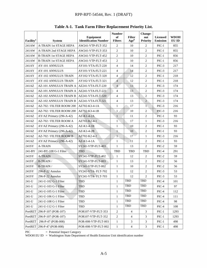
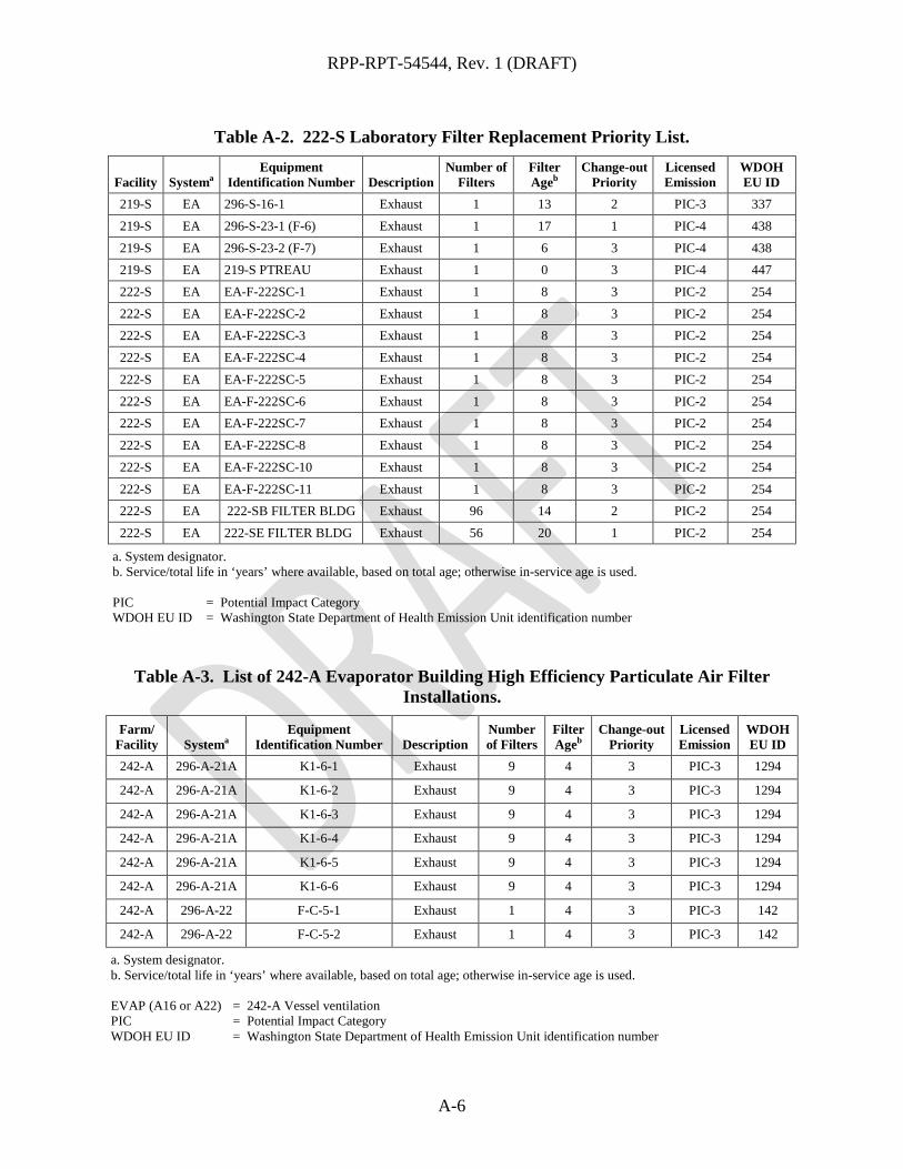
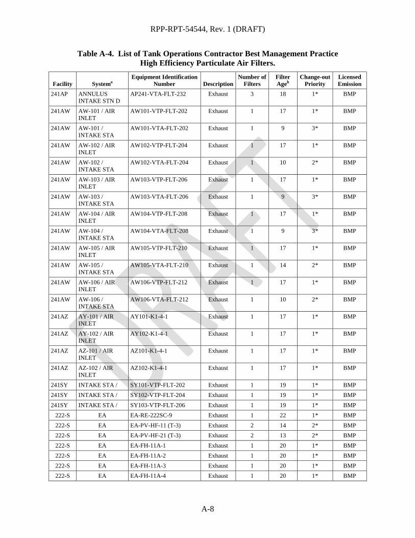
The tables in this section identify the list of TOC HEPA filters that need to be replaced before compliance with a 10 year operating life is established under the HEPA filter management plan program. The HEPA filters listed in Tables A-1, A-2, and A-3 constitute a backlog of what needs to be scheduled for replacement based on the service/total life of the HEPA filters. The HEPA filters listed in a particular row may be combined with other filters when a work package is prepared for field work in order to change out a bank/train of filters. The HEPA filters listed in Tables A-1, A-2, and A-3 have been evaluated based on the licensed emission units designations and have been prioritized based on the listed service life. The first set of priorities will be based on PIC-1 and PIC-2 units because of their potential to contribute to the regulatory offsite dose limit. PIC-3 and PIC-4 units are of lower priority. The BMP HEPA filters listed in Table A-4 are not regulated by WDOH and are included in this management plan for completeness and replacement associated cost should the existing performance based approach identify the need for a different change-out frequency.
Table A-1. Tank Farm Filter Replacement Priority List.
Facilitya System Equipment
Identification Number
Number of
Filters Filter Ageb
Change-out
Priority Licensed Emission
WDOH EU ID
241AN A-TRAIN 1st STAGE AN241-VTP-FLT-352 2 11 2 PIC-1 735
241AN A-TRAIN EX / 2nd STAGE AN241-VTP-FLT-353 2 11 2 PIC-1 735
241AN B-TRAIN EX / 1st STAGE AN241-VTP-FLT-452 2 11 2 PIC-1 736 241AN B-TRAIN EX / 2nd STAGE AN241-VTP-FLT-453 2 10 2 PIC-1 736
241AN TRAIN A / AN241-VTA-FLT-701 4 18 1 PIC-3 228
241AN TRAIN A / AN241-VTA-FLT-702 4 18 1 PIC-3 228
241AN TRAIN B / AN241-VTA-FLT-802 4 18 1 PIC-3 228 241AN TRAIN B / AN241-VTA-FLT-801 4 14 2 PIC-3 228
241AP 296-A-41 / TRAIN A AP241-VTA-FLT-701 9 18 1 PIC-2 205
241AP 296-A-41 / TRAIN B AP241-VTA-FLT-801 9 18 1 PIC-2 205
241AP 296-A-41 / TRAIN B AP241-VTA-FLT-802 9 18 1 PIC-2 205 241AP K2-4-6 / TRAIN A AP241-VTA-FLT-702 9 18 1 PIC-2 205
241AP PRIMARY EXHAUST TRAIN A
AP241-VTP-FLT-302 1 10 2 PIC-2 204
241AP PRIMARY EXHAUST TRAIN A
AP241-VTP-FLT-303 1 10 2 PIC-2 204
241AP PRIMARY EXHAUST TRAIN B
AP241-VTP-FLT-403 1 10 2 PIC-2 204
241AP PRIMARY EXHAUST TRAIN B
AP241-VTP-FLT-402 1 10 2 PIC-2 204
241AW ANNULUS EXHAUST / TRAIN A
AW241-VTA-FLT-701 4 18 1 PIC-3 156
241AW ANNULUS EXHAUST / TRAIN A
AW241-VTA-FLT-702 4 18 1 PIC-3 156
241AW ANNULUS TRAIN B AW241-VTA-FLT-801 4 18 1 PIC-3 156
241AW ANNULUS TRAIN B AW241-VTA-FLT-802 4 18 1 PIC-3 156
RPP-RPT-54544, Rev. 1 (DRAFT)
A-5
Table A-1. Tank Farm Filter Replacement Priority List.
Facilitya System Equipment
Identification Number
Number of
Filters Filter Ageb
Change-out
Priority Licensed Emission
WDOH EU ID
241AW A-TRAIN 1st STAGE HEPA AW241-VTP-FLT-352 2 10 2 PIC-1 855
241AW A-TRAIN 2nd STAGE HEPA AW241-VTP-FLT-353 2 10 2 PIC-1 855
241AW B-TRAIN 1st STAGE HEPA AW241-VTP-FLT-452 2 10 2 PIC-1 856
241AW B-TRAIN 1st STAGE HEPA AW241-VTP-FLT-453 2 10 2 PIC-1 856 241AY AY-101 ANNULUS AY101-VTA-FLT-220 4 14 2 PIC-3 217
241AY AY-101 ANNULUS AY101-VTA-FLT-221 4 14 2 PIC-3 217
241AY AY-102 ANNULUS TRAIN AY102-VTA-FLT-320 4 12 2 PIC-1 218
241AY AY-102 ANNULUS TRAIN AY102-VTA-FLT-321 4 12 2 PIC-1 218 241AZ AZ-101 ANNULUS TRAIN A AZ241-VTA-FLT-220 4 13 2 PIC-3 174
241AZ AZ-101 ANNULUS TRAIN A AZ241-VTA-FLT-221 4 13 2 PIC-3 174
241AZ AZ-102 ANNULUS TRAIN B AZ241-VTA-FLT-320 4 13 2 PIC-3 174 241AZ AZ-102 ANNULUS TRAIN B AZ241-VTA-FLT-321 4 13 2 PIC-3 174
241AZ AZ-702 / FILTER ROOM 200 AZ702-K3-4-1A 1 17 1 PIC-3 216
241AZ AZ-702 / FILTER ROOM 200 AZ702-K3-4-1B 1 10 2 PIC-3 216
241AZ AY/AZ Primary (296-A-42) AZ-K1-4-2A 1 11 2 PIC-1 93 241AZ AZ-702 / FILTER ROOM A AZ702-K2-4-1 1 17 1 PIC-3 216
241AZ AY/AZ Primary (296-A-42) AZ-K1-4-1B 1 10 2 PIC-1 93
241AZ AY/AZ Primary (296-A-42) AZ-K1-4-2B 1 10 2 PIC-1 93
241AZ AZ-702 / FILTER ROOM B AZ702-K2-4-2 1 17 1 PIC-3 216 241AZ AY/AZ Primary (296-A-42) AZ-K1-4-1A 1 11 2 PIC-1 93
241SY A-TRAIN SY241-VTP-FLT-403 1 13 2 PIC-2 59
241-BY 241-BY-108 G-1 Filter TBD TBD TBD TBD PIC-4 291
241SY A-TRAIN SY241-VTP-FLT-402 1 12 2 PIC-2 59 241SY B-TRAIN / SY241-VTP-FLT-003 1 13 2 PIC-2 56
241SY B-TRAIN / SY241-VTP-FLT-002 1 10 2 PIC-2 56
241SY 296-P-22 Annulus SY241-VTA- FLT-702 1 12 2 PIC-3 53
241SY 296-P-22 Annulus SY241-VTA- FLT-703 1 12 2 PIC-3 53 241-U 241-U-102 G-1 Filter TBD 1 TBD TBD PIC-4 101
241-U 241-U-103 G-1 Filter TBD 1 TBD TBD PIC-4 97
241-U 241-U-105 G-1 Filter TBD 1 TBD TBD PIC-4 112
241-U 241-U-106 G-1 Filter TBD 1 TBD TBD PIC-4 111 241-U 241-U-108 G-1 Filter TBD 1 TBD TBD PIC-4 98
241-U 241-U-112 G-1 Filter TBD 1 TBD TBD PIC-4 108
PortRET 296-P-107 (POR-107) POR107-VTP-FLT-353 2 4 3 PIC-1 1293
PortRET 296-P-107 (POR-107) POR107-VTP-FLT-352 2 4 3 PIC-1 1293 PortRET 296-P-47 (POR-008) POR-008-VTP-FLT-003 1 3 3 PIC-1 498
PortRET 296-P-47 (POR-008) POR-008-VTP-FLT-002 1 4 3 PIC-1 498
PIC = Potential Impact Category WDOH EU ID = Washington State Department of Health Emission Unit identification number
RPP-RPT-54544, Rev. 1 (DRAFT)
A-6
Table A-2. 222-S Laboratory Filter Replacement Priority List.
Facility Systema Equipment
Identification Number Description Number of
Filters Filter Ageb
Change-out Priority
Licensed Emission
WDOH EU ID
219-S EA 296-S-16-1 Exhaust 1 13 2 PIC-3 337
219-S EA 296-S-23-1 (F-6) Exhaust 1 17 1 PIC-4 438
219-S EA 296-S-23-2 (F-7) Exhaust 1 6 3 PIC-4 438 219-S EA 219-S PTREAU Exhaust 1 0 3 PIC-4 447
222-S EA EA-F-222SC-1 Exhaust 1 8 3 PIC-2 254
222-S EA EA-F-222SC-2 Exhaust 1 8 3 PIC-2 254 222-S EA EA-F-222SC-3 Exhaust 1 8 3 PIC-2 254
222-S EA EA-F-222SC-4 Exhaust 1 8 3 PIC-2 254
222-S EA EA-F-222SC-5 Exhaust 1 8 3 PIC-2 254
222-S EA EA-F-222SC-6 Exhaust 1 8 3 PIC-2 254 222-S EA EA-F-222SC-7 Exhaust 1 8 3 PIC-2 254
222-S EA EA-F-222SC-8 Exhaust 1 8 3 PIC-2 254
222-S EA EA-F-222SC-10 Exhaust 1 8 3 PIC-2 254
222-S EA EA-F-222SC-11 Exhaust 1 8 3 PIC-2 254 222-S EA 222-SB FILTER BLDG Exhaust 96 14 2 PIC-2 254
222-S EA 222-SE FILTER BLDG Exhaust 56 20 1 PIC-2 254
a. System designator. b. Service/total life in ‘years’ where available, based on total age; otherwise in-service age is used. PIC = Potential Impact Category WDOH EU ID = Washington State Department of Health Emission Unit identification number
Table A-3. List of 242-A Evaporator Building High Efficiency Particulate Air Filter Installations.
Farm/ Facility Systema
Equipment Identification Number Description
Number of Filters
Filter Ageb
Change-out Priority
Licensed Emission
WDOH EU ID
242-A 296-A-21A K1-6-1 Exhaust 9 4 3 PIC-3 1294
242-A 296-A-21A K1-6-2 Exhaust 9 4 3 PIC-3 1294
242-A 296-A-21A K1-6-3 Exhaust 9 4 3 PIC-3 1294
242-A 296-A-21A K1-6-4 Exhaust 9 4 3 PIC-3 1294
242-A 296-A-21A K1-6-5 Exhaust 9 4 3 PIC-3 1294
242-A 296-A-21A K1-6-6 Exhaust 9 4 3 PIC-3 1294
242-A 296-A-22 F-C-5-1 Exhaust 1 4 3 PIC-3 142
242-A 296-A-22 F-C-5-2 Exhaust 1 4 3 PIC-3 142
a. System designator. b. Service/total life in ‘years’ where available, based on total age; otherwise in-service age is used. EVAP (A16 or A22) = 242-A Vessel ventilation PIC = Potential Impact Category WDOH EU ID = Washington State Department of Health Emission Unit identification number

RPP-RPT-54544, Rev. 1 (DRAFT)
A-7
Table A-4. List of Tank Operations Contractor Best Management Practice High Efficiency Particulate Air Filters.
Facility Systema Equipment Identification
Number Description Number of
Filters Filter Ageb
Change-out Priority
Licensed Emission
241AN AN-101 / AIR CTL ST
AN101-VTP-FLT-202 Exhaust 1 16 1* BMP
241AN AN-101 / INTAKE STN
AN101-VTA-FLT-202 Exhaust 1 18 1* BMP
241AN AN-102 / AIR CTL ST
AN102-VTP-FLT-204 Exhaust 1 10 2* BMP
241AN AN-102 / INTAKE STN
AN102-VTA-FLT-204 Exhaust 1 18 1* BMP
241AN AN-103 / AIR CTL ST
AN103-VTP-FLT-206 Exhaust 1 17 1* BMP
241AN AN-103 / INTAKE STN
AN103-VTA-FLT-206 Exhaust 1 18 1* BMP
241AN AN-104 / AIR CTL ST
AN104-VTP-FLT-208 Exhaust 1 17 1* BMP
241AN AN-104 / INTAKE STN
AN104-VTA-FLT-208 Exhaust 1 18 1* BMP
241AN AN-105 / AIR CTL ST
AN105-VTP-FLT-210 Exhaust 1 17 1* BMP
241AN AN-105 / INTAKE STN
AN105-VTA-FLT-210 Exhaust 1 18 1* BMP
241AN AN-106 / AIR CTL ST
AN106-VTP-FLT-212 Exhaust 1 16 1* BMP
241AN AN-106 / INTAKE STN
AN106-VTA-FLT-212 Exhaust 1 18 1* BMP
241AN AN-107 / AIR CTL ST
AN107-VTP-FLT-214 Exhaust 1 17 1* BMP
241AN AN-107 / INTAKE STN
AN107-VTA-FLT-214 Exhaust 1 18 1* BMP
241AP ANNULUS INTAKE STN A
AP241-VTA-FLT-202 Exhaust 3 18 1* BMP
241AP ANNULUS INTAKE STN B
AP241-VTA-FLT-212 Exhaust 3 18 1* BMP
241AP ANNULUS INTAKE STN C
AP241-VTA-FLT-222 Exhaust 3 18 1* BMP
RPP-RPT-54544, Rev. 1 (DRAFT)
A-8
Table A-4. List of Tank Operations Contractor Best Management Practice High Efficiency Particulate Air Filters.
Facility Systema Equipment Identification
Number Description Number of
Filters Filter Ageb
Change-out Priority
Licensed Emission
241AP ANNULUS INTAKE STN D
AP241-VTA-FLT-232 Exhaust 3 18 1* BMP
241AW AW-101 / AIR INLET
AW101-VTP-FLT-202 Exhaust 1 17 1* BMP
241AW AW-101 / INTAKE STA
AW101-VTA-FLT-202 Exhaust 1 9 3* BMP
241AW AW-102 / AIR INLET
AW102-VTP-FLT-204 Exhaust 1 17 1* BMP
241AW AW-102 / INTAKE STA
AW102-VTA-FLT-204 Exhaust 1 10 2* BMP
241AW AW-103 / AIR INLET
AW103-VTP-FLT-206 Exhaust 1 17 1* BMP
241AW AW-103 / INTAKE STA
AW103-VTA-FLT-206 Exhaust 1 9 3* BMP
241AW AW-104 / AIR INLET
AW104-VTP-FLT-208 Exhaust 1 17 1* BMP
241AW AW-104 / INTAKE STA
AW104-VTA-FLT-208 Exhaust 1 9 3* BMP
241AW AW-105 / AIR INLET
AW105-VTP-FLT-210 Exhaust 1 17 1* BMP
241AW AW-105 / INTAKE STA
AW105-VTA-FLT-210 Exhaust 1 14 2* BMP
241AW AW-106 / AIR INLET
AW106-VTP-FLT-212 Exhaust 1 17 1* BMP
241AW AW-106 / INTAKE STA
AW106-VTA-FLT-212 Exhaust 1 10 2* BMP
241AZ AY-101 / AIR INLET
AY101-K1-4-1 Exhaust 1 17 1* BMP
241AZ AY-102 / AIR INLET
AY102-K1-4-1 Exhaust 1 17 1* BMP
241AZ AZ-101 / AIR INLET
AZ101-K1-4-1 Exhaust 1 17 1* BMP
241AZ AZ-102 / AIR INLET
AZ102-K1-4-1 Exhaust 1 17 1* BMP
241SY INTAKE STA / SY101-VTP-FLT-202 Exhaust 1 19 1* BMP 241SY INTAKE STA / SY102-VTP-FLT-204 Exhaust 1 19 1* BMP
241SY INTAKE STA / SY103-VTP-FLT-206 Exhaust 1 19 1* BMP
222-S EA EA-RE-222SC-9 Exhaust 1 22 1* BMP
222-S EA EA-PV-HF-11 (T-3) Exhaust 2 14 2* BMP 222-S EA EA-PV-HF-21 (T-3) Exhaust 2 13 2* BMP
222-S EA EA-FH-11A-1 Exhaust 1 20 1* BMP
222-S EA EA-FH-11A-2 Exhaust 1 20 1* BMP
222-S EA EA-FH-11A-3 Exhaust 1 20 1* BMP 222-S EA EA-FH-11A-4 Exhaust 1 20 1* BMP

RPP-RPT-54544, Rev. 1 (DRAFT)
A-9
Table A-4. List of Tank Operations Contractor Best Management Practice High Efficiency Particulate Air Filters.
Facility Systema Equipment Identification
Number Description Number of
Filters Filter Ageb
Change-out Priority
Licensed Emission
222-S EA EA-GB-11A-1 Exhaust 1 6 3* BMP
222-S EA EA-RE-11A-1 Exhaust 1 20 1* BMP 222-S EA EA-RE-11A-2 Exhaust 1 20 1* BMP
222-S EA EA-RE-11A-3 Exhaust 1 20 1* BMP
222-S EA EA-RE-11A-4 Exhaust 1 20 1* BMP
222-S EA EA-RE-11A-6 Exhaust 1 20 1* BMP 222-S EA EA-RE-11A-7 Exhaust 1 20 1* BMP
222-S EA EA-RE-1A-1 Exhaust 1 25 1* BMP
222-S EA 1A Hot Cell Exhaust 1 18 1* BMP
222-S EA EA-FH-1B-1 Exhaust 1 18 1* BMP 222-S EA EA-FH-1B-2 Exhaust 1 18 1* BMP
222-S EA EA-FH-1B-3 Exhaust 1 18 1* BMP
222-S EA EA-FH-1B-4 Exhaust 1 18 1* BMP
222-S EA EA-FH-1B-5 Exhaust 1 18 1* BMP 222-S EA EA-FH-1B-6 Exhaust 1 18 1* BMP
222-S EA EA-FH-1B-7 Exhaust 1 18 1* BMP
222-S EA EA-FH-1B-8 Exhaust 1 18 1* BMP
222-S EA EA-FH-1B-9 Exhaust 1 18 1* BMP 222-S EA EA-FH-1C-1 Exhaust 1 17 1* BMP
222-S EA EA-FH-1C-4 Exhaust 1 3 3* BMP
222-S EA EA-GB-1C-A Exhaust 1 17 1* BMP
222-S EA EA-GB-1C-B Exhaust 1 17 1* BMP 222-S EA EA-FH-1D-1 Exhaust 1 18 1* BMP
222-S EA EA-FH-1D-2 Exhaust 1 18 1* BMP
222-S EA EA-FH-1D-3 Exhaust 1 18 1* BMP
222-S EA EA-FH-1D-4 Exhaust 1 18 1* BMP 222-S EA EA-FH-1D-5 Exhaust 1 18 1* BMP
222-S EA EA-FH-1D-6 Exhaust 1 18 1* BMP
222-S EA EA-FH-1D-7 Exhaust 1 18 1* BMP 222-S EA EA-FH-1D-8 Exhaust 1 18 1* BMP
222-S EA EA-FH-1E-1 Exhaust 1 16 1* BMP
222-S EA EA-FH-1E-2 Exhaust 1 19 1* BMP
222-S EA 1E1 Hot Cell In-Cell Exhaust 3 22 1* BMP 222-S EA 1E2 Hot Cell Exhaust 1 9 3* BMP
222-S EA EA-FH-1F-5 Exhaust 1 16 1* BMP
222-S EA 1E2 Hot Cell In-Cell Exhaust 2 20 1* BMP
222-S EA EA-RE-T4-1 (T-4) Exhaust 1 29 1* BMP 222-S EA EA-RE-T4-2 (T-4) Exhaust 1 29 1* BMP
222-S EA EA-RE-T8-1 (T-8) Exhaust 1 20 1* BMP

RPP-RPT-54544, Rev. 1 (DRAFT)
A-10
Table A-4. List of Tank Operations Contractor Best Management Practice High Efficiency Particulate Air Filters.
Facility Systema Equipment Identification
Number Description Number of
Filters Filter Ageb
Change-out Priority
Licensed Emission
222-S EA EA-RE-T8-2 (T-8) Exhaust 1 15 2* BMP
222-S EA EA-FH-1GA-1 Exhaust 1 22 1* BMP 222-S EA EA-FH-1GA-2 Exhaust 1 22 1* BMP
222-S EA EA-FH-1GA-3 Exhaust 1 22 1* BMP
222-S EA EA-FH-1GA-4 Exhaust 1 22 1* BMP
222-S EA EA-FH-1GA-5 Exhaust 1 22 1* BMP 222-S EA EA-FH-1GC-1 Exhaust 1 25 1* BMP
222-S EA EA-FH-1J-ICP-1 Exhaust 1 22 1* BMP
222-S EA EA-FH-1J-ICP-1B Exhaust 1 22 1* BMP
222-S EA EA-FH-1J-ICP-2 Exhaust 1 3 3* BMP 222-S EA EA-RE-1J-1 Exhaust 1 27 1* BMP
222-S EA EA-FH-1K-1 Exhaust 1 19 1* BMP
222-S EA EA-FH-1K-2 Exhaust 1 4 3* BMP
222-S EA EA-FH-1GB-2 Exhaust 1 10 3* BMP 222-S EA EA-FH-1GB-3 Exhaust 1 22 1* BMP
222-S EA EA-FH-1GB-5 Exhaust 1 22 1* BMP
222-S EA EA-FH-1GB-6 Exhaust 1 22 1* BMP
222-S EA EA-FH-1L-1 Exhaust 1 10 3* BMP 222-S EA EA-FH-1L-3 Exhaust 1 19 1* BMP
222-S EA EA-FH-1L-5 Exhaust 1 29 1* BMP
222-S EA EA-FH-1L-6 Exhaust 1 22 1* BMP
222-S EA EA-FH-2B-1 Exhaust 1 4 3* BMP 222-S EA EA-RE-2A-1 Exhaust 1 25 1* BMP
222-S EA EA-FH-2B-2 Exhaust 1 4 3* BMP
222-S EA EA-FH-2B-3 Exhaust 1 13 2* BMP
222-S EA EA-FH-2B-16 Exhaust 2 30 1* BMP 222-S EA EA-RE-2B1-1 Exhaust 1 27 1* BMP
222-S EA EA-FH-2B2-2 Exhaust 1 4 3* BMP
222-S EA EA-FH-2B2-3 Exhaust 1 25 1* BMP 222-S EA EA-FH-2D-1 Exhaust 1 22 1* BMP
222-S EA EA-RE-2E-1 Exhaust 1 20 1* BMP
222-S EA EA-FH-2H-1 Exhaust 1 10 3* BMP
222-S EA EA-FH-2H-2 Exhaust 1 31 1* BMP 222-S EA EA-RE-2A-1 Exhaust 1 25 1* BMP
222-S EA EA-FH-4A-1 Exhaust 1 24 1* BMP
222-S EA EA-FH-4A-3 Exhaust 1 4 3* BMP
222-S EA EA-FH-4A-4 Exhaust 1 5 3* BMP 222-S EA EA-FH-4A-5 Exhaust 1 5 3* BMP
222-S EA EA-FH-4A-7 Exhaust 1 13 2* BMP

RPP-RPT-54544, Rev. 1 (DRAFT)
A-11
Table A-4. List of Tank Operations Contractor Best Management Practice High Efficiency Particulate Air Filters.
Facility Systema Equipment Identification
Number Description Number of
Filters Filter Ageb
Change-out Priority
Licensed Emission
222-S EA EA-FH-4A-9 Exhaust 1 24 1* BMP
222-S EA EA-FH-4A-11 Exhaust 1 11 2* BMP 222-S EA EA-FH-4A-12 Exhaust 1 24 1* BMP
222-S EA EA-FH-4B-1 Exhaust 1 18 2* BMP
222-S EA EA-FH-4B-2 Exhaust 1 18 1* BMP
222-S EA EA-FH-4B-3 Exhaust 1 11 2* BMP 222-S EA EA-FH-4B-4 Exhaust 1 18 2* BMP
222-S EA EA-FH-4B-5 Exhaust 1 11 2* BMP
222-S EA EA-FH-4B-6 Exhaust 1 18 1* BMP
222-S EA EA-FH-4B-7 Exhaust 1 18 1* BMP 222-S EA EA-FH-4B-8 Exhaust 1 18 1* BMP
222-S EA EA-FH-4B-9 Exhaust 1 18 1* BMP
222-S EA EA-FH-4B-10 Exhaust 1 18 1* BMP
222-S EA EA-FH-4B-11 Exhaust 1 18 1* BMP 222-S EA EA-FH-4B-12 Exhaust 1 18 1* BMP
222-S EA EA-FH-4C-1 Exhaust 1 >25.0 1* BMP
222-S EA EA-FH-4C-2 Exhaust 1 >25.0 1* BMP
222-S EA EA-RE-4C-3 Exhaust 1 >25.0 1* BMP 222-S EA EA-FH-4C-4 Exhaust 1 16 1* BMP
222-S EA EA-FH-4C-5 Exhaust 1 >25.0 1* BMP
222-S EA EA-FH-4C-6 Exhaust 1 >25.0 1* BMP
222-S EA EA-FH-4C-7 Exhaust 1 >25.0 1* BMP 222-S EA EA-FH-4C-9 Exhaust 1 17 1* BMP
222-S EA EA-FH-4C-11 Exhaust 1 >25.0 1* BMP
222-S EA EA-FH-4C-12 Exhaust 1 >25.0 1* BMP
222-S EA EA-FH-4D-7 Exhaust 1 4 3* BMP 222-S EA EA-FH-4D-11 Exhaust 1 4 3* BMP
222-S EA EA-FH-4E-1 Exhaust 1 18 1* BMP
222-S EA EA-FH-4E-2 Exhaust 1 18 1* BMP 222-S EA EA-FH-4E-10 Exhaust 1 18 1* BMP
222-S EA EA-FH-4E-11 Exhaust 1 18 1* BMP
222-S EA EA-FH-4E-12 Exhaust 1 18 1* BMP
222-S EA EA-FH-4H-1 Exhaust 1 14 2* BMP 222-S EA EA-FH-4H-2 Exhaust 1 >25.0 1* BMP
222-S EA EA-FH-4H-3 Exhaust 1 8 3* BMP
222-S EA EA-FH-4H-4 Exhaust 1 >25.0 1* BMP
222-S EA EA-FH-4H-5 Exhaust 1 >25.0 1* BMP 222-S EA EA-FH-4H-6 Exhaust 1 >25.0 1* BMP
222-S EA EA-FH-4H-7 Exhaust 1 >25.0 1* BMP

RPP-RPT-54544, Rev. 1 (DRAFT)
A-12
Table A-4. List of Tank Operations Contractor Best Management Practice High Efficiency Particulate Air Filters.
Facility Systema Equipment Identification
Number Description Number of
Filters Filter Ageb
Change-out Priority
Licensed Emission
222-S EA EA-FH-4H-8 Exhaust 1 >25.0 1* BMP
222-S EA EA-FH-4H-9 Exhaust 1 14 2* BMP 222-S EA EA-FH-4H-10 Exhaust 1 8 3* BMP
222-S EA EA-FH-4H-12 Exhaust 1 4 3* BMP
222-S EA EA-FH-4J-1 Exhaust 1 18 1* BMP
222-S EA EA-FH-4J-2 Exhaust 1 18 1* BMP 222-S EA EA-FH-4J-3 Exhaust 1 18 1* BMP
222-S EA EA-FH-4J-4 Exhaust 1 10 2* BMP
222-S EA EA-FH-4J-5 Exhaust 1 18 1* BMP
222-S EA EA-FH-4J-6 Exhaust 1 18 1* BMP 222-S EA EA-FH-4J-7 Exhaust 1 18 1* BMP
222-S EA EA-FH-4J-8 Exhaust 1 18 1* BMP
222-S EA EA-FH-4J-9 Exhaust 1 18 1* BMP
222-S EA EA-FH4J-10 Exhaust 1 14 2* BMP 222-S EA EA-FH-4J-11 Exhaust 1 18 1* BMP
222-S EA EA-FH-4J-12 Exhaust 1 18 1* BMP
222-S EA EA-FH-4K-1 Exhaust 1 15 2* BMP
222-S EA EA-FH-4K-3 Exhaust 1 6 3* BMP 222-S EA EA-FH-4K-4 Exhaust 1 31 1* BMP
222-S EA EA-FH-4K-7 Exhaust 1 10 2* BMP
222-S EA EA-FH-4K-9 Exhaust 1 10 1* BMP
222-S EA EA-FH-4K-10 Exhaust 1 22 1* BMP 222-S EA EA-FH-4K-11 Exhaust 1 6 3* BMP
222-S EA EA-FH-4K-12 Exhaust 1 18 1* BMP
222-S EA EA-FH-4L-1 Exhaust 1 18 1* BMP
222-S EA EA-FH-4L-2 Exhaust 1 18 1* BMP 222-S EA EA-FH-4L-4 Exhaust 1 18 1* BMP
222-S EA EA-FH-4L-5 Exhaust 1 18 1* BMP
222-S EA EA-FH-4L-6 Exhaust 1 18 1* BMP 222-S EA EA-FH-4L-7 Exhaust 1 18 1* BMP
222-S EA EA-FH-4L-8 Exhaust 1 18 1* BMP
222-S EA EA-FH-4L-12 Exhaust 1 18 1* BMP
222-S EA EA-FH-4L-10 Exhaust 1 18 1 PIC-4 222-S EA EA-FH-4L-11 Exhaust 1 18 1 PIC-4
222-S EA EA-FH-4M-1 Exhaust 1 13 2* BMP
222-S EA EA-FH-4M-2 Exhaust 1 11 2* BMP
222-S EA EA-FH-4M-3 Exhaust 1 19 1* BMP 222-S EA EA-FH-4M-4 Exhaust 1 19 1* BMP
222-S EA EA-FH-4N-1 Exhaust 1 >25.0 1* BMP

RPP-RPT-54544, Rev. 1 (DRAFT)
A-13
Table A-4. List of Tank Operations Contractor Best Management Practice High Efficiency Particulate Air Filters.
Facility Systema Equipment Identification
Number Description Number of
Filters Filter Ageb
Change-out Priority
Licensed Emission
222-S EA EA-FH-4N-2 Exhaust 1 >25.0 1* BMP
222-S EA EA-FH-4N-3 Exhaust 1 >25.0 1* BMP 222-S EA EA-FH-4N-6 Exhaust 1 >25.0 1* BMP
222-S EA EA-RE-4N-5 Exhaust 1 32 1* BMP
222-S EA EA-FH-4N-7 Exhaust 1 9 3* BMP
222-S EA EA-FH-4N-8 Exhaust 1 24 1* BMP 222-S EA EA-FH-4N-10 Exhaust 1 >25.0 1* BMP
222-S EA EA-FH-4P-8 Exhaust 1 3 3* BMP
222-S EA EA-FH-4P-10 Exhaust 1 3 3* BMP
222-S EA EA-FH-4Q-1 Exhaust 1 9 3* BMP 222-S EA EA-FH-4R-4 Exhaust 1 9 3* BMP
222-S EA EA-FH-4S-3 Exhaust 1 28 1* BMP
222-S EA EA-FH-4S-4 Exhaust 1 28 1* BMP
222-S EA EA-FH-4S-6 Exhaust 1 28 1* BMP 222-S EA EA-FH-4S-8 Exhaust 1 28 1* BMP
222-S EA EA-FH-4S-10 Exhaust 1 14 2* BMP
222-S EA EA-FH-4S-11 Exhaust 1 28 1* BMP
222-S EA EA-FH-4TUV-1 Exhaust 1 10 3* BMP 222-S EA EA-RE-4TUV-2 Exhaust 1 10 3* BMP
222-S EA EA-RE-S3B-1 Exhaust 1 20 1* BMP
222-S EA EA-RE-S3B-2 Exhaust 1 20 1* BMP
222-S EA EA-FH-5A/B-1 Exhaust 1 3 3* BMP 222-S EA EA-FH-5A/B-3 Exhaust 1 3 3* BMP
222-S EA 11A Hot Cell Inlet 1 20 1* BMP
222-S EA EA-GB-11A-1 Inlet 1 6 3* BMP
222-S EA EA-F-CFX-PIT Inlet 1 34 1* BMP 222-S EA 1A Hot Cell Inlet 1 20 1* BMP
222-S EA EA-GB-1C-A Inlet 1 17 1* BMP
222-S EA EA-GB-1C-B Inlet 1 17 1* BMP 222-S EA 1E1 Hot Cell Inlet 1 7 3* BMP
222-S EA 1E2 Hot Cell Inlet 1 22 1* BMP
222-S EA 1F Hot Cell Inlet 1 3 3* BMP
222-S EA HCC-F-1 Exhaust 1 13 2* BMP 222-S EA HCC-F-2 Exhaust 1 13 2* BMP
222-S EA HCC-F-3 Exhaust 1 13 2* BMP
222-S EA EA-F-11A-8 Exhaust 1 8 3* BMP
222-S EA EA-F-11A-9 Exhaust 1 20 1* BMP 222-S EA EA-F-CFX Exhaust 1 20 1* BMP
222-S EA EA-F-CFX/B1F Exhaust 1 34 1* BMP
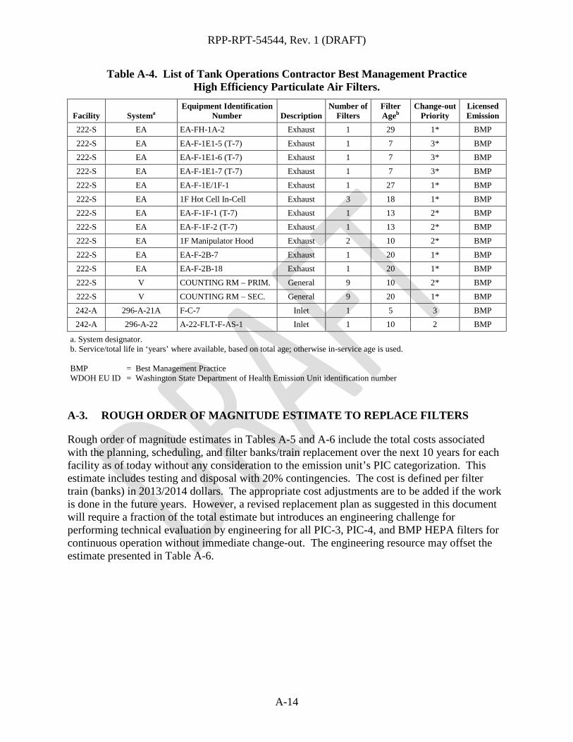
RPP-RPT-54544, Rev. 1 (DRAFT)
A-14
Table A-4. List of Tank Operations Contractor Best Management Practice High Efficiency Particulate Air Filters.
Facility Systema Equipment Identification
Number Description Number of
Filters Filter Ageb
Change-out Priority
Licensed Emission
222-S EA EA-FH-1A-2 Exhaust 1 29 1* BMP
222-S EA EA-F-1E1-5 (T-7) Exhaust 1 7 3* BMP 222-S EA EA-F-1E1-6 (T-7) Exhaust 1 7 3* BMP
222-S EA EA-F-1E1-7 (T-7) Exhaust 1 7 3* BMP
222-S EA EA-F-1E/1F-1 Exhaust 1 27 1* BMP
222-S EA 1F Hot Cell In-Cell Exhaust 3 18 1* BMP 222-S EA EA-F-1F-1 (T-7) Exhaust 1 13 2* BMP
222-S EA EA-F-1F-2 (T-7) Exhaust 1 13 2* BMP
222-S EA 1F Manipulator Hood Exhaust 2 10 2* BMP
222-S EA EA-F-2B-7 Exhaust 1 20 1* BMP 222-S EA EA-F-2B-18 Exhaust 1 20 1* BMP
222-S V COUNTING RM – PRIM. General 9 10 2* BMP
222-S V COUNTING RM – SEC. General 9 20 1* BMP
242-A 296-A-21A F-C-7 Inlet 1 5 3 BMP 242-A 296-A-22 A-22-FLT-F-AS-1 Inlet 1 10 2 BMP
a. System designator. b. Service/total life in ‘years’ where available, based on total age; otherwise in-service age is used. BMP = Best Management Practice WDOH EU ID = Washington State Department of Health Emission Unit identification number A-3. ROUGH ORDER OF MAGNITUDE ESTIMATE TO REPLACE FILTERS
Rough order of magnitude estimates in Tables A-5 and A-6 include the total costs associated with the planning, scheduling, and filter banks/train replacement over the next 10 years for each facility as of today without any consideration to the emission unit’s PIC categorization. This estimate includes testing and disposal with 20% contingencies. The cost is defined per filter train (banks) in 2013/2014 dollars. The appropriate cost adjustments are to be added if the work is done in the future years. However, a revised replacement plan as suggested in this document will require a fraction of the total estimate but introduces an engineering challenge for performing technical evaluation by engineering for all PIC-3, PIC-4, and BMP HEPA filters for continuous operation without immediate change-out. The engineering resource may offset the estimate presented in Table A-6.
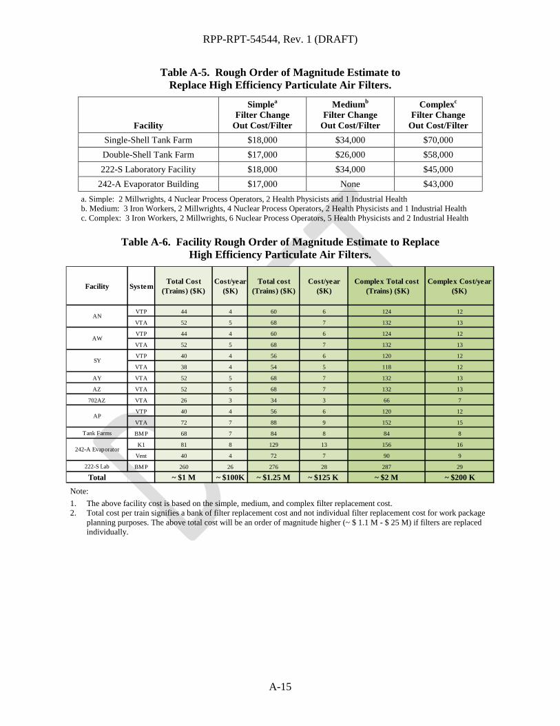
RPP-RPT-54544, Rev. 1 (DRAFT)
A-15
Table A-5. Rough Order of Magnitude Estimate to Replace High Efficiency Particulate Air Filters.
Facility
Simplea Filter Change
Out Cost/Filter
Mediumb Filter Change
Out Cost/Filter
Complexc Filter Change
Out Cost/Filter Single-Shell Tank Farm $18,000 $34,000 $70,000 Double-Shell Tank Farm $17,000 $26,000 $58,000 222-S Laboratory Facility $18,000 $34,000 $45,000
242-A Evaporator Building $17,000 None $43,000 a. Simple: 2 Millwrights, 4 Nuclear Process Operators, 2 Health Physicists and 1 Industrial Health b. Medium: 3 Iron Workers, 2 Millwrights, 4 Nuclear Process Operators, 2 Health Physicists and 1 Industrial Health c. Complex: 3 Iron Workers, 2 Millwrights, 6 Nuclear Process Operators, 5 Health Physicists and 2 Industrial Health
Table A-6. Facility Rough Order of Magnitude Estimate to Replace
High Efficiency Particulate Air Filters.
Note: 1. The above facility cost is based on the simple, medium, and complex filter replacement cost. 2. Total cost per train signifies a bank of filter replacement cost and not individual filter replacement cost for work package
planning purposes. The above total cost will be an order of magnitude higher (~ $ 1.1 M - $ 25 M) if filters are replaced individually.
Facility SystemTotal Cost
(Trains) ($K)Cost/year
($K)Total cost
(Trains) ($K)Cost/year
($K)Complex Total cost
(Trains) ($K)Complex Cost/year
($K)
VTP 44 4 60 6 124 12
VTA 52 5 68 7 132 13
VTP 44 4 60 6 124 12
VTA 52 5 68 7 132 13
VTP 40 4 56 6 120 12
VTA 38 4 54 5 118 12
AY VTA 52 5 68 7 132 13
AZ VTA 52 5 68 7 132 13
702AZ VTA 26 3 34 3 66 7
VTP 40 4 56 6 120 12
VTA 72 7 88 9 152 15
Tank Farms BMP 68 7 84 8 84 8
K1 81 8 129 13 156 16
Vent 40 4 72 7 90 9
222-S Lab BMP 260 26 276 28 287 29
Total ~ $1 M ~ $100K ~ $1.25 M ~ $125 K ~ $2 M ~ $200 K
AN
AW
SY
AP
242-A Evaporator