tarzan
DESCRIPTION
laserTRANSCRIPT
COL 9(5), 051402(2011) CHINESE OPTICS LETTERS May 10, 2011
Deformation behavior of laser bending of
circular sheet metal
Q. Nadeem∗ and S. J. Na
Department of Mechanical Engineering, KAIST, Yuseong-Gu, Daejeon, South Korea∗Corresponding author: [email protected]
Received October 26, 2010; accepted January 3, 2011; posted online April 18, 2011
The application of a thermal source in non-contact forming of sheet metal has long been used. However, thereplacement of this thermal source with a laser beam promises much greater controllability of the process.This yields a process with strong potential for application in aerospace, shipbuilding, automobile, andmanufacturing industries, as well as the rapid manufacturing of prototypes and adjustment of misalignedcomponents. Forming is made possible through laser-induced non-uniform thermal stresses. In this letter,we use the geometrical transition from rectangular to circle-shaped specimen and ring-shaped specimen toobserve the effect of geometry on deformation in laser forming. We conduct a series of experiments on awide range of specimen geometries. The reasons for this behavior are also analyzed. Experimental resultsare compared with simulated values using the software ABAQUS. The utilization of line energy is found tobe higher in the case of laser forming along linear irradiation than along curved ones. We also analyze theeffect of strain hindrance. The findings of the study may be useful for the inverse problem, which involvesacquiring the process parameters for a known target shape of a wide range of complex shape geometries.
OCIS codes: 140.0140, 160.0160.doi: 10.3788/COL201109.051402.
Forming techniques consist of metal working processes inwhich the material is shaped in solid state by plastic de-formation. There are two classifications of forming tech-niques: bulk forming and sheet forming. Bulk formingcomprises rolling, extrusion, and forging. On the otherhand, bending and contouring are common processes ofsheet forming. Conventionally, sheet metal bending us-ing punch and die requires hard tooling, external forces,and spring back action. The idea of using lasers forforming sheet metal was first conceived by Kitamura inJapan[1]. The laser forming process is concerned withthe bending and correction of sheet metals/tubes usinga laser beam. Laser forming of sheet metal componentsand tubes requires no hard tooling and external forces,and is therefore suited for die-less rapid prototyping andlow-volume, high-variety production of sheet metal andtube components. Moshaiov et al.[2] showed that theprocess was similar to the well established torch flamebending used on large sheet material in the ship-buildingindustry, but it offered much more control over the finalproduct.
In recent years, laser forming techniques have beeninvestigated extensively. Empirical, analytical, and fi-nite element method (FEM) tools[3,4] have been usedto predict the distortions and relation between bend-ing angle and process parameters, such as power of thelaser beam, speed at which the laser beam scans thesheet metal, and the laser beam spot diameter, amongothers. Most researches have focused on the laser form-ing along linear irradiation paths and over rectangularplates. Different irradiation strategies have to be devel-oped for the production of complex shaped parts (e.g., aspherical dome). A certain deformation can be obtainedif the laser beam scans the sheet several times along thesame path. Edwardson et al.[5] studied the forming pro-cess of saddle-shaped parts using five different scanning
strategies. Their results showed that the warped de-formation occurred because of the dissymmetry of laserirradiations.
The effect of processing parameters on the deformationis not simple because we change linear scanning pathsto curved paths. Similarly, laser forming of the circularshape specimens have deformation behaviors differentfrom rectangular shapes. Hennige proposed a path strat-egy for ring and circle segments, but the range of segmentangle was limited and the work did not explain the rea-sons for using arbitrary paths to obtain dome shape[6].Paths used do not provide information regarding theoffset between successive laser scanning passes, whichinitiates the need for further understanding of the pro-cess of laser forming along curved irradiations and curvedgeometry as well.
In this letter, we present the change in deformationbehavior during transition from linear to curved geome-tries and irradiations. A significant change of the processmechanisms and its dependencies on the part geome-try can be ascertained. The forming of axis-symmetricshapes that include ring-shaped geometry and circle-shaped geometry is investigated and compared withrectangular-shaped geometry. Moreover, the effects ofstrain hindrance on the deformation are investigated.All the experimental results are compared with simu-lated values using the software ABAQUS.
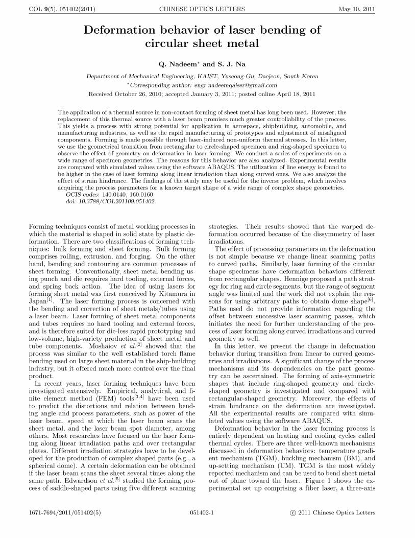
Deformation behavior in the laser forming process isentirely dependent on heating and cooling cycles calledthermal cycles. There are three well-known mechanismsdiscussed in deformation behaviors: temperature gradi-ent mechanism (TGM), buckling mechanism (BM), andup-setting mechanism (UM). TGM is the most widelyreported mechanism and can be used to bend sheet metalout of plane toward the laser. Figure 1 shows the ex-perimental set up comprising a fiber laser, a three-axis
1671-7694/2011/051402(5) 051402-1 c© 2011 Chinese Optics Letters

COL 9(5), 051402(2011) CHINESE OPTICS LETTERS May 10, 2011
Fig. 1. Experimental Setup.
Fig. 2. Schematic of the laser bending setup.
computure numerical control (CNC) table, and a laserdisplacement sensor. The fiber laser used had a maxi-mum power of 100 W and a motion assistant was usedto control the three-axis CNC table.
If the specimen is not so large and the spot size is lessthan or nearly equal to the sheet thickness, the TGMmechanism is dominant for acquiring a given shape. Fur-thermore, the bending is always toward the laser beam,namely, positive bending (Fig. 2). We also apply positivebending with an adjustment of the process parametersin this study. The bending angle was measured by laserdisplacement sensor. To simplify the process, the ve-locity of laser scanning beam and radius of concentricheating paths r were kept constant at 720 mm/min and30 mm, respectively, whereas the power of the laser beamP varied during the experiments otherwise stated. Allspecimens were made of common engineering low-carbonsteel.
There were thus two basic part geometries, one ofwhich can be considered as a circular plate having tworadii (outer and inner radii), named ring-shaped spec-imen, and the other as a circular plate with an outerradius only, named circle-shaped specimen. The ge-ometries mentioned above were selected to describe thetransition from linear to curved irradiation laser bending.The circle-shaped specimens had a total radius of 50 mm,whereas the ring-shaped specimens had an outer radiusof 50 mm and an inner radius of 10 mm. All specimenshad a thickness of 0.8 mm. To enhance laser absorptionby the workpiece, graphite coating was applied to the ir-radiated surface[7]. The segment angle β is defined as thetotal central angle of a specimen. This segment angle fora particular specimen is further subdivided into a num-ber of small divisions called “in-plane angle α”. Figure 3
illustrates three of the part geometries used in the exper-iments: Fig. 3(a) depicts circle-shaped specimen with β= 90◦, Fig. 3(b) depicts ring-shaped specimen with β =90◦, and Fig. 3(c) depicts ring-shaped specimen with β= 180◦. Radial lines along the circumferential directionshow in-plane angles of 45◦, 90◦, 135◦, and 180◦, respec-tively. The objective of the in-plane angle is to measurethe bending angle along the concentric heating path at adefinite radius.
As a general rule, the minimum number of measur-ing locations or number of divisions of segment anglealong the heating paths is three. To compensate for edgeeffects, the bending angle was not measured at or veryclose to the edges of specimens. The values of bendingangles shown here were taken as the root-mean-square(RMS) average of measured angles at different in-planeangles. The time delay between any two consecutivepasses was 90 s in case of multiple irradiations.
In addition to the geometries mentioned above, forcomparison, rectangular plates acting as a reference basewith varying segment angles were taken. These spec-imens were of constant length of 50 mm, whereas thewidth (heating source moving parallel to the width ofplate) was equal to the length of concentric heatingpaths. One set of geometries for the segment angle of90◦ is shown in Fig. 4. For instance, the width w of areferenced rectangular plate for definite segment angle is
Fig. 3. Definition of circular part geometries, segment angleβ, and in-plane angle α while concentric paths describe theheating path radius ri. (a) Circle-shaped specimen, β = 90◦;(b) ring-shaped specimen, β = 90◦; (c) ring-shaped specimen,β = 180◦.
Fig. 4. Referenced rectangular, circle-shaped, and ring-shaped specimens (left to right), β = 90◦, r = 30 mm.
041003-2

COL 9(5), 051402(2011) CHINESE OPTICS LETTERS May 10, 2011
defined as w = ri × βi, where ri is the radius of heatingpath, and βi is the segment angle (in radians).
A specially designed jig that can rotate about the z-axis was used to facilitate accurate measurements.
A series of experiments for ring-shaped, circle-shaped,and referenced rectangular specimens were conducted fora range of 5◦ < β < 180◦. In addition to these experi-ments, a second series of investigations with constant β= 180◦, P = 80 W, r = 30 mm, and varying inner radiusfrom 0 to 25 mm were carried out.
If the sheet metal is relatively thin, the influence ofstrain hardening and material thickening along the bend-ing edge is almost insignificant when the number of irra-diations is small[8]. Hence, a linear relationship betweenbending angle and number of irradiations exists.
Figure 4 shows one set of formed specimens after exper-iments on the ring-shaped, circle-shaped, and referencedrectangular specimens. The laser had a spot diameter of1 mm, and its power was maintained at a constant valueof 80 W. Figure 5 clearly shows the influence of differentirradiation geometries on the achievable bending anglefor the case of multiple irradiations or number of passes(N).
As mentioned earlier, a series of experiments were con-ducted for all three kinds of specimens with different βvalues. Figure 6 shows some of the formed ring-shapedspecimens, with β = 45◦, 90◦, 120◦, and 180◦. The over-all bending angle was determined by the continuous heat-ing and cooling events as well as the associated thermaleffects[9]. The results of experiments are shown in Fig.7. From the figure, the bending angle is clearly smallerfor all specimens with β = 5◦. This is because the sur-rounding cooled material is not sufficient to restrict theexpansion of irradiated surface in the heating cycle. As aresult, the material has the maximum counter bending,and during cooling cycles, the irradiated surface has com-paratively less positive bending at the end of the formingprocess. When the segment angle increases up to 45◦, thebending angle digressively increases for all three kinds ofspecimens. Different scanning methods showed differentbending behaviors due to the dissimilar nature of fac-tors affecting the deformation behavior. One importantfactor is geometrical constraint. Referenced rectangularspecimens at particular segment angles have larger de-formation than ring-shaped and circle-shaped specimens.This means that for linear irradiations, the maximumstresses utilized for deformation and the produced strainshave an insignificant amount of strain hindrance. It wassuggested that the line energy for linear irradiations isgreater than that for curved irradiations[10]. Thus, defor-mations for linear irradiations are greater than those forcurved irradiations. Another aspect has been describedby Jung that during circular heating, strain historiesexhibit greater thermal strain effect than plastic strainduring heating[11]. Thus, the restraint or bending rigid-ity of the plate becomes non-symmetric, resulting in lessbending angle. Hennige described the strong influenceof the geometrical process induced strain hindrance onthe forming results in the circle-line heating process[12].The degree of the bend angle was digressive comparedwith the straight-line heating process. Other factors thathave to be addressed might influence the residual stressesand change the forming mechanism itself. This behavior
occurs at very early stages during forming, such as β =5◦.
In the case of referenced rectangular specimens, thebending angle continued to increase digressively up toa measured saturation value. On the other hand, forring-shaped and circle-shaped specimens, 45◦< β <120◦,the bending angle decreased continuously. We also no-ticed that longitudinal distortion was induced when β >45◦. When β >120◦, the bending angle again startedto increase for ring-shaped specimens but continued todecrease for circle-shaped specimens. For circle-shapedspecimens, the strain hindrance had a strong negativeeffect on deformation. It implies that the complex math-ematical analysis of combined effect of circumferentialand radial stresses and longitudinal distortion is required.
Fig. 5. Relation between bending angle and number of passes(N). β = 90◦, d = 1 mm, P = 80 W.
Fig. 6. Ring-shaped specimens after forming with β = 45◦,90◦, 120◦, and 180◦.
Fig. 7. Effect of transition geometries on deformation. P =80 W, N = 15.
041003-3

COL 9(5), 051402(2011) CHINESE OPTICS LETTERS May 10, 2011
Among the ring-shaped and circle-shaped specimens,the latter has some additional amount of material nearthe inner side with varying influence along the circum-ference, which acts as a strong strain hindrance. If thestrain hindrance is increased further using circle-shapedspecimens instead of ring-shaped specimens, the achiev-able bending angle decreases in comparison with the cor-responding ring-shaped specimens[6]. Therefore, circle-shaped specimens have smaller bending angles comparedwith ring-shaped specimens. If the inner radius of ring-shaped specimen is varied, it will have a negative orpositive influence on deformation.
Experiments with a spot size of 1 mm, heating path-radius of 30 mm, and varying inner radius of ring-shapedspecimens were carried out. Figure 8 describes the statedeffect for half-circular ring-shaped specimen (β = 180◦).The bending angle increases with increasing inner radiusuntil edge effects dominate.
Zero value of the inner radius corresponded to thecircle-shaped specimen. As shown in the figure, thebending angle decreases at an inner radius of 25 mm.Obviously, the reason for this was the edge effects be-cause the heating path’s radius of 30 mm and the innerradius of ring-shaped specimen of 25 mm were closer toeach other. Therefore, the edge effects were significant.
FEM is a very strong and effective tool to study thelaser forming process. The different stages of the processsuch as the developing of counter bending and the con-traction during cooling could be identified with the useof FE simulations. Numerical simulation for curved irra-diation paths on rectangular sheet and ring sheet metalshas been studied[13,14]. The software used in this studyfor FE analysis was ABAQUS. A subroutine was alsorequired for a simulation made in FORTRAN. It was anonlinear, transient complex analysis that required sim-plifying assumptions, including the following aspects: 1)material is isotropic; 2) laser operates in continuous wavemode; 3) no melting occurs; 4) no external mechanicalforce exists; 5) variation of material parameters withtemperature has been obtained by means of linear inter-polation; 6) the metal plate is flat and free of residualstresses.
In the analysis, the heat source distribution was aGaussian distribution. Furthermore, natural convec-tion and radiation were used as boundary conditions foranalysis. Process parameters similar to the actual pro-cess were also considered. Temperature-dependent ther-mal and mechanical material properties for low-carbonsteel were taken from Ref. [7]. The temperature ranged
Fig. 8. Effect of strain hindrance at β = 180◦. Bending an-gle increases with increasing inner radius until edge effectsappear. Path radius is 30 mm, P = 80 W, N = 15.
Fig. 9. FE simulation. Deformation is clearly toward the laserbeam source. Ring-shaped specimen, β = 180◦.
from 0 to 1400 ◦C with increments of 100 ◦C. All ofthe physical properties at any temperature can be deter-mined by interpolation[3]. To ensure the quality of theanalysis, unknown properties were considered throughlinear interpolation. These material properties weredefined in ABAQUS program during the “defining ma-terial” stage[13].
FE analysis was sequential type, i.e., to conclude thedeformation (structural analysis) behavior, output ofthermal analysis was needed. Therefore, thermal analy-sis was finished before structural analysis. All the otherprocess parameters considered in the FE analysis weresimilar with the ones used during experiments.
For verification of experimental results, a series of sim-ulations was ran for ring-shaped specimens within theβ range of 0◦–180◦ and N = 1. Figure 9 shows the FEsimulation model of ring-shaped specimen with β = 180◦
only. The result after simulation clearly showed the de-formation toward the laser beam.
As described above, the value of bending angle wasthe RMS average of values measured at various locationsalong definite concentric paths or in-plane angles. Fig-ure 10 describes the validity of considered RMS valueof bending angle. There is clearly a negligible devia-tion along the definite concentric path and experimentalresults match the FE simulation results. Additionally,for comparison, a series of numerical investigations wasconducted for a number of ring-shaped specimens withβ = 0◦–180◦ at N = 15. Figure 11 illustrates the resultsof comparison between FE analysis calculations and ex-perimental measured values. The deformation behaviorduring experiments indicates a very good correlationwith FE investigations.
In conclusion, a series of investigation is carried outusing experimental and numerical methods to analyzethe influence of the curved irradiations and geometrytransitions on deformation behavior in laser forming
Fig. 10. Bending angle variation along definite concentricpaths is insignificant as shown by experiments and FE simu-lation.
041003-4

COL 9(5), 051402(2011) CHINESE OPTICS LETTERS May 10, 2011
Fig. 11. Results of FE simulations and experiments have verygood correlation, with negligible deviation, for ring-shapedspecimens with β = 0◦–180◦.
process. Our investigations show that linear irradia-tion paths for rectangular plates have more deformationthan curved irradiation paths for ring-shaped and circle-shaped specimens. This means that the utilization ofline energy, and thus stresses for linear irradiations, ishigher. Deformation along the particular concentricpath has negligible deviation, which indicates the po-tential of curved irradiations for three-dimensional (3D)laser forming. The specimens having additional mate-rial near the center, such as the circle-shaped specimens,have less deformation than the ring-shaped specimens.The reason proposed is strain hindrance. FE analysisby ABAQUS software is found to be a very strong toolto predict the deformation behavior and provides verygood correlation between numerically found and experi-mentally measured values of bending angles. To obtainimproved understanding and control over the process,
further study is needed. Future work will concentrateon the extension of β range from 0◦ to 360◦ and thehandling of inverse problem to determine the processparameters for a given deformation or target shape forsuch kinds of geometries. Moreover, the influence of theseunderlying factors would be determined by utilizing nu-merical simulations under the laws of bending mechanics.
References
1. N. Kitamura, “Technical report of joint project on mate-rials processing by high power laser” JWES-TP-8302 359(1983).
2. A. Moshaiov and W. Vorus, J. Ship Res. 31, 269 (1987).
3. Z. Ji and S. Wu, J. Mater. Process. Tech. 74, 89 (1998).
4. A. K. Kyrsanidi, Th. B. Kermanidis, and S. G. Pante-lakis, J. Mater. Process. Tech. 104, 94 (2000).
5. S. P. Edwardson, K. G. Watkins, G. Dearden, and J.Magee, in Proceedings of the 3rd International Confer-ence on Laser Assisted Net Shaping 559 (2001).
6. T. Hennige, J. Mater. Process. Tech. 103, 102 (2001).
7. J. Kim and S. J. Na, Opt. Laser Technol. 35, 605 (2003).
8. J. Bao and Y. L. Yao, J. Manuf. Sci. Eng. 123, 53(2001).
9. Z. Hu, R. Kovacevic, and M. Labudovic, Int. J. MachineTools and Manufacture 42, 1427 (2002).
10. Q. Nadeem, W. J. Seong, and S. J. Na, in Proceedings ofAutumn Annual Conference of KWJS 52, 22 (2009).
11. H. C. Jung, “A study on laser forming processes withfinite element analysis” PhD. Thesis (University of Can-terbury, Christchurch, 2006).
12. T. Hennige, in Proceedings of the LANE’97 409 (1997).
13. P. Zhang, J. Yu, and X. Zheng, Tsinghua Sci. Technol.14, 132 (2009).
14. P. Zhang, B. Guo, D. B. Shan, and Z. Ji, J. Mater. Pro-cess. Tech. 184, 157 (2007).
051402-5