tascam - 8track.jdwilson.ca · multitrack cassette recorder the 488 records on readily available...
TRANSCRIPT

TASCAM TEAC Professional Division
488
5700123804

Table Of Contents
Safety Instructions 3 Introduction 4 The Recording System 5-6
The three steps to multitrack 6 Understanding the Mixer 7-8
Signal flow in the 488 mixer 7 Cue monitor system 7
Multitrack Cassette Recorder 9 Track Format and Tape Recommendations 9-10 Block Diagram 11 Brief Guide 12-15 Step-By-Step Operations Guide 16-24
Let's tray the 488 mixer 16 How to record on track 1 18 How to make an overdub on track 2 20 How to record all other tracks 20 How to record many sources
onto a single track 22 How to record multiple tracks
simultaneously 22 How to mix down 23
Using Memory Location Points 25-26 Loading MEMO points 25 Locating the tape 26
Repeat Play 27 PUNCH-IN or INSERT Recording 28-30
REHEARSE function 28 Punch-in/out procedure 28 Punch-in/out with RECORD 29 Using RECORD FUNCTION switch 30 Using the remote footswitch (RC-30P) 30
Bouncing Tracks (Ping-Pong) 31-32 Ping-pong procedure 31 Ping-pong in stereo procedure 32
Using Effects with the PORTASTUDIO 488 33-34 Setting effect send levels 33 Setting the output level of effect devices 33 Setting the mix/balance control
on effect devices 33 How to connect your effects devices 34
Recording with TAPE SYNC 35 Features and Controls 36-43
488 Mixer Input section 36 Tape monitor section 37 Channel controls 37 Channel assignment section • 37 Effect send section 38 Stereo input section 38 Group master section 40 Monitor section 40
488 Recorder Cassette loading and dbx system 41 Transport-controls 41 Track controls 42 Displays 42 Auto locators 3 Sync features 43
Care and Maintenance 44-45 Cleaning 44 Degaussing (demagnetizing) 45
How the dbx Works 45 Troubleshooting 46 Specifications 46-48 Level Diagrams 49-50 Optional Accessories 51
Safety Instructions
CAUTION: • Read all of these instructions. • Save these instructions for later use. • Follow all warnings and instructions marked on the
audio equipment.
1. Read Instructions — All the safety and operating instructions should be read before the appliance is operated.
2. Retain Instructions — The safety and operating instructions should be retained for future reference.
3. Heed Warnings — All warnings on the appliance and in the operating instructions should be adhered to.
4. Follow Instructions — All operating and use instructions should be followed.
5. Water and Moisture — The appliance should not be used near water — for example, near a bathtub, washbowl, kitchen sink, laundry tub, in a wet basement, or near a swimming pool, etc.
6. Carts and Stands — The appliance should be used only with a cart or stand that is recommended by the manufacturer.
6A. An appliance and cart combination should be moved with care. Quick stops, excessive force, and uneven surfaces may cause the appliance and cart combination to overturn.
7. Wall or Ceiling Mounting - The appliance should be mount¬ ed to a wall or ceiling only as recommended by the manu¬ facturer.
8. Ventilation — The appliance should be situated so that its location or position does not interfere with its proper venti¬ lation. For example, the appliance should not be situated on a bed, sofa, rug, or similar surface that may block the ventilation openings; or, placed in a built-in installation, such as a bookcase or cabinet that may impede the flow of air through the ventilation openings.
9. Heat — The appliance should be situated away from heat sources such as radiators, heat registers, stoves, or other appliances (including amplifiers) that produce heat.
10. Power Sources — The appliance should be connected to a power supply only of the type described in the operating in¬ structions or as marked on the appliance.
11. Grounding or Polarization — The precautions that should be taken so that the grounding or polarization means of an appliance is not defeated.
12. Power-Cord Protection — Power-supply cords should be routed so that they are not likely to be walked on or pinch¬ ed by items placed upon or against them, paying particular attention to cords at plugs, convenience receptacles, and the point where they exit from the appliance.
13. Cleaning — The appliance should be cleaned only as recom¬ mended by the manufacturer.
14. Power Lines — An outdoor antenna should be located away from power lines.
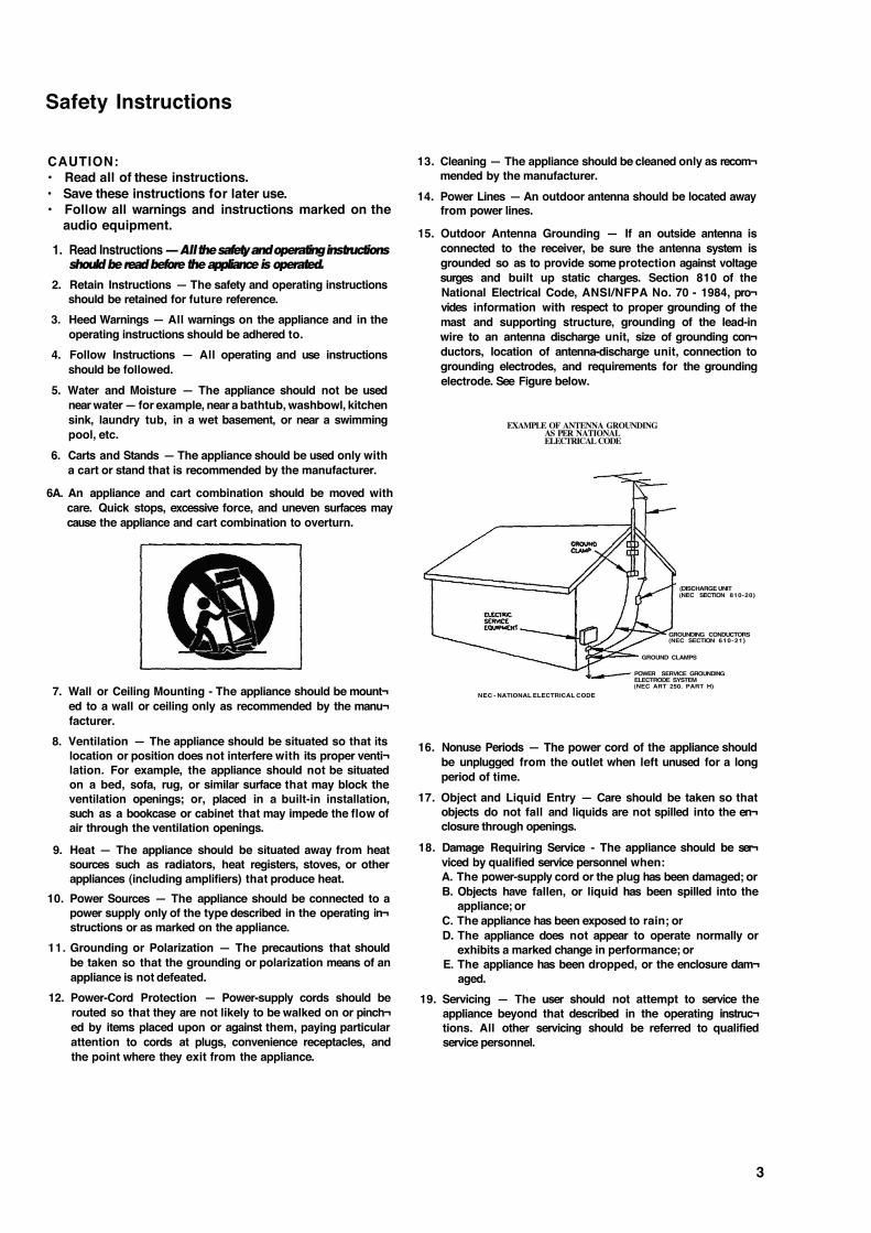
15. Outdoor Antenna Grounding — If an outside antenna is connected to the receiver, be sure the antenna system is grounded so as to provide some protection against voltage surges and built up static charges. Section 810 of the National Electrical Code, ANSI/NFPA No. 70 - 1984, pro¬ vides information with respect to proper grounding of the mast and supporting structure, grounding of the lead-in wire to an antenna discharge unit, size of grounding con¬ ductors, location of antenna-discharge unit, connection to grounding electrodes, and requirements for the grounding electrode. See Figure below.
EXAMPLE OF ANTENNA GROUNDING AS PER NATIONAL ELECTRICAL CODE
NEC - NATIONAL ELECTRICAL CODE
(DISCHARGE UNIT (NEC SECTION 810-20)
GROUNDING CONDUCTORS (NEC SECTION 610-21)
GROUND CLAMPS
POWER SERVICE GROUNDING ELECTRODE SYSTEM (NEC ART 250. PART H)
16. Nonuse Periods — The power cord of the appliance should be unplugged from the outlet when left unused for a long period of time.
17. Object and Liquid Entry — Care should be taken so that objects do not fall and liquids are not spilled into the en¬ closure through openings.
18. Damage Requiring Service - The appliance should be ser¬ viced by qualified service personnel when: A. The power-supply cord or the plug has been damaged; or B. Objects have fallen, or liquid has been spilled into the
appliance; or C. The appliance has been exposed to rain; or D. The appliance does not appear to operate normally or
exhibits a marked change in performance; or E. The appliance has been dropped, or the enclosure dam¬
aged. 19. Servicing — The user should not attempt to service the
appliance beyond that described in the operating instruc¬ tions. All other servicing should be referred to qualified service personnel.
3
Introduction
The PORTASTUDIO 488 is...
The PORTASTUDIO 488 is an 8-track "Multitrack Master" cassette tape recorder and a full-function mixer with 12 inputs/4 outputs combined into a single workstation.
Its high audio quality and creative flexibility reflect the experience and innovation that have allowed TASCAM to earn its reputation in professional audio production fields, and its user-friendly design makes the 488 suitable for anyone, from expert to novice.
Using this manual : To get the most out of your 488, please take the time to read through this manual. Some time spent now will keep you from overlooking some of the features that make the 488 a more creative tool. You may discover some new tricks you haven't tried before.
Use of capital letters : In general, we use all upper case type to designate a particular switch, control, jack name or label (like PAN). Transport modes and some features are described with an upper case first letter (like Record mode).
NOTE FOR U.K. CUSTOMERS
U.K. Customers Only: Due to the variety of plugs being used in the
U.K.; this unit is sold without an AC plug. Please request your dealer to install the correct plug to match the mains power outlet where your unit will be used as per these instructions.
IMPORTANT
The wires in this mains lead colored in accordance with the following code:
BLUE: NEUTRAL BROWN: LIVE
in
As the colours of the wires in the mains lead of this apparatus may not correspond with the coloured markings identifying the terminals of your plug, proceed as follows:
The wire Which is coloured BLUE must be connected to the terminal which is marked with the letter N or coloured BLACK. The wire which is coloured BROWN must be connected to the terminal which is marked with the letter L or coloured RED.
This product is manufactured to comply with the
radio interference of EEC directive "82/499/EEC."
THIS DIGITAL APPARATUS DOES NOT EX-CEED THE CLASS B LIMITS FOR RADIO NOISE EMISSIONS FROM DIGITAL APPARA-TUS AS SET OUT IN THE RADIO INTER-FERENCE REGULATIONS OF THE CANADIAN DEPARTMENT OF COMMUNICATIONS.
4

The Recording System
The PORTASTUDIO 488 is a complete audio production facility in a single box. It is divided into two major sections: a full-function mixer and an 8-channel, multitrack cassette recorder. To complete the recording system, you'll
additionally need these: Input devices (microphones, instruments). Output devices (headphones), 2-track recorder, Effects processors, etc.
5

The Three Steps to Multitrack
The diagram below depicts how signals from equipment connected to the 488 can be routed.
In TRACKING and Overdubbing, the mixer inputs are usually microphones or instruments, going IC. different tracks of the recorder. In OVERDUBBING, the MONITOR section and TAPE CUE of the mixer must be used to listen to previous tracks while you record new ones, so there is a two-way flow through the console. In MIXDOWN, signal comes from the multitrack and is sent to an external 2-track recorder.
6

Understanding the Mixer
Signal Flow in the 488 mixer
The illustration below shows how the input signal passes through the 488 Mixer section. After the MASTER faders they go to the GROUP
OUT jacks and the multitrack recorder (not shown). This is the most important signal route in the mixer and is called "Main Mix".
To Tape
(RECORD FUNCTION switches)

Cue Monitor System
The CUE mix and MONITOR switches are also crucial for successful multitrack recording, because they control what you hear in the headphones. This CUE mix is totally independent from the Main Mix going to tape. If you don't use the CUE mix, you run the risk of accidentally "bouncing tracks" every time you record new material.
The TAPE control in each of the first 8 channels gets its signal from the multitrack recorder, and sends playback to either the Main Mix, or the CUE Monitor. When all of these TAPE controls are turned to the right (CUE), and CUE is pressed in the MONITOR switch, you can hear tape playback in the headphones. You can adjust the monitor level of each track by adjusting its TAPE control. The channels of the Main Mix remain free to handle external inputs for recording.
The five MONITOR Source switches choose which mix(es) you can hear in the PHONES - the CUE mix, and any of the four GROUPS. You press the applicable GROUP switch to hear what you are recording: for example, GROUP 4 while recording onto Track 4.
If you need to add external sources to the CUE mix (for example, a MIDI-synchronized drum machine that you don't want to record on tape), the INPUT ASSIGN switches for channels 5 to 8 have a CUE position. This sends the LINE IN jack signal directly to the CUE mix. (In this case, the LINE IN signal is disconnected from the mixer channel controls, so there must be a volume control on the source device.)
8

Multitrack Cassette Recorder
The 488 records on readily available standard (Philips) Compact Cassette tape, high bias Type II. The recorder has 8 tracks while the mixer has 4 group outs; you can record a maximum of 4 tracks at one time. For more details, see "How to Record Multiple Tracks Simultaneously", page 22.
The 488's dbx Noise Reduction virtually eliminates unwanted tape noise. A special SYNC feature turns off the dbx on track 8 separately, making it possible to record and play back the MIDI sync tones or SMPTE/EBU time code without being affected by the dbx encode/decode. This ensures that the sync tones/code are recorded and played back without unnecessary processing. With proper operating techniques, it is not necessary to leave a guard band between music and sync tone tracks because of the low crosstalk of the TASCAM heads.
reliable functions that make the unit easier to use:
• A three position autolocator (MEMO 1 and 2 and Zero) allows key positions to be located automatically.
• REPEAT allows a section to be played over and over between the MEM01 and MEM02 points for rehearsal.
• RHSL (rehearsal) allows you to "preview" what your recording will sound like and repeat the record punch in/out sequence as many times as you wish before actually executing it on tape.
• The tape speed can be increased or decreased with the PITCH CONTROL dial in both playback and record, to match pitch or for special effects.
The transport controls of the 488 are microprocessor operated, allowing highly
• Punch-in and Punch-out can be engaged using the optional RC-30P footswitch, which gives you an "extra hand" in the recording process.
Track Format and Tape Recommendations
The Portastudio 488 uses a basic speed of 9.5 cm/sec. (3-3/4 ips) which is two times (2X) the normal speed of a standard audio cassette. It also employs a discrete 8-channel format head
developed especially by TEAC for TASCAM multitrack cassette recorders. Here is a comparision of various cassette formats:
9
Tapes recorded on stereo cassette recorders will not playback properly on the 488 because of the differences in the track format and tape speed. For the same reasons, tapes recorded on the Portastudio 488 will not playback properly on stereo cassette recorders. Material recorded on the 488 must be mixed down to stereo for final distribution.
The 488 needs the entire width of the tape to record its eight tracks, eliminating the option of recording on both sides (actually, it's both directions). Therefore, you should decide which side (side- "A" or side "B") you want to use and use that side exclusively. It's a good idea to get into habit of consistently using the same side on all multitrack tapes.
Tape Type The Portastudio 488 is internally adjusted for HIGH BIAS "Type II" tape. For best results, you should only use tapes of this type. TDK SA, Maxell XL-II or equivalent formulations are recommended. We strongly suggest that you select one good quality brand and use it exclusively. The time you spend creating your multitrack master is much more valuable than the money you save by buying inferior tape. The cassette shell essentially becomes a part of the 488's transport. Poor quality shells can cause wrinkles, snarls and shredding of the edges of the tape with use. Even small scratches on the tape oxide can cause "dropouts" (temporary loss of signal) on one or more tracks. High quality tapes are less likely to cause problems in the long run.
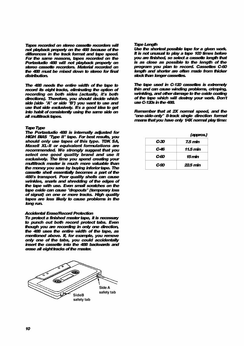
Accidental Erase/Record Protection To protect a finished master tape, it is necessary to punch out both record protect tabs. Even though you are recording in only one direction, the 488 uses the entire width of the tape, as mentioned above. If, for example, you remove only one of the tabs, you could accidentally insert the cassette into the 488 backwards and erase all eight tracks of the master.
Tape Length Use the shortest possible tape for a given work. It is not unusual to play a tape 100 times before you are finished, so select a cassette length that is as close as possible to the length of the program you plan to record. Cassettes C-60 length and shorter are often made from thicker stock than longer cassettes.
The tape used in C-120 cassettes is extremely thin and can cause winding problems, crimping, wrinkling, and other damage to the oxide coating of the tape which will destroy your work. Don't use C-120s in the 488.
Remember that at 2X normal speed, and the "one-side-only" 8-track single direction format means that you have only 1/4X normal play time:
(approx.)
C-30 7.5 min
C-46 11.5 min
C-60 15 min
C-90 22.5 min
SideB safety tab
Side A safety tab
10
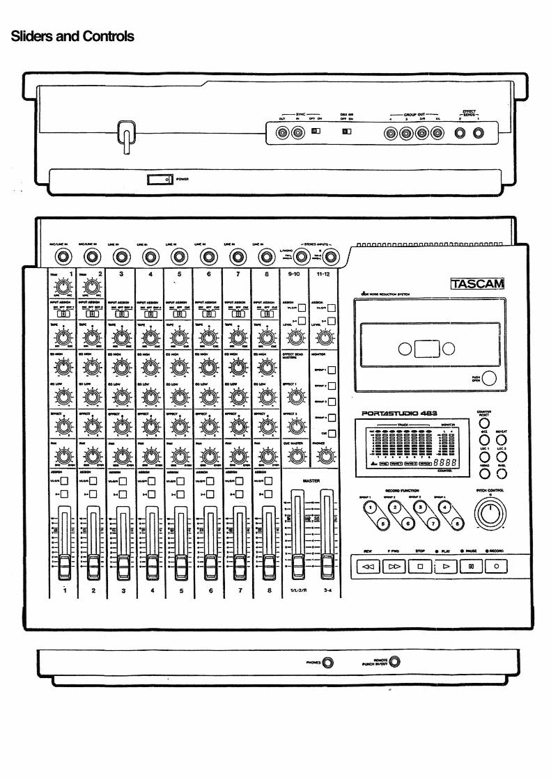
Sliders and Controls

Brief Guide
Input selection and adjustment
MIC/LINE IN (Ch. 1-2) or LINE IN (Ch. 3-8): These are the input jacks for the mixer channels. Connect line-level signals to any channel; connect lower-level signals (from microphones and some guitar pickups) to the MIC/LINE INs (channel 1 or 2).
TRIM (Ch. 1-2 only): Sets how much preamplification will be added to the MIC/LINE IN jack. Turn to the right if the signal needs amplification, to the left if the signal is so loud it is distorting the mixer electronics.
•INPUT ASSIGN: Determines where the IN jack signal will go to. MIX sends it through the mixer channel, and is the normal setting.
OFF is used during a typical mixdown.
GRP 1-4. or CUE sends the input signal directly to a GROUP or the CUE mix, bypassing the channel controls - this makes the IN jack work as a "buss input", for use with external mixers or other line inputs that don't need channel control.
• If you are using MIDI-sequenced "virtual tracks", connect them to channels 5-8, so they can be sent directly to the CUE mix without being recorded.
Tape Mix/Cue
This acts as a combination level and assignment control for the corresponding tape track. • At center (12 o'clock), the tape signal is off and cant be heard. • Turn it to the left of center (MIX) to send the tape signal through the mixer
channel. - If INPUT ASSIGN is also in its MIX position, the tape return and the input signal will both go through the mixer channel simultaneously. - Turn it all the way to the left and turn INPUT ASSIGN off to make tape the only source of the channel at mixdown.
• Turn it to the right of center (CUE) to send the tape signal to the CUE mix for monitoring through headphones.
Equalization and Effect send
•EQ HIGH: Cuts or boosts treble frequencies. Its shelving point is 10 kHz; it can affect frequencies down to 2 kHz.
EQ LOW: Cuts or boosts bass frequencies. Shelving type, 100 Hz, can affect frequencies up to 500 Hz.
• EFFECT: A post-fader effect send from the channel. The center position is OFF. Turn to the left to send signal to Effect Send Master 1, and to the right to send signal to Effect Send Master 2.
Channel Output section
-ASSIGN switches: Press to send the output of the channel to any (or all) of four output groups for recording onto the multitrack. Works in cooperation with PAN.
• PAN: Sets the pan position (left-right balance) of the channel between odd/even groups (left for 1 & 3, right for 2 & 4, center for all).
- Channel fader: Sets the volume of the channel feeding the group master faders.
12

STEREO INPUTS (Channel 9-12)
STEREO INPUTS: Connect any line-level signal (such as an effect return, or electronic instrument) here. They can operate in three different ways. • Four Sources: By using a special 3-conductor Tip-
Ring-Sleeve (TRS) cable, each jack can accept two signals at once (Tip to the left. Ring to the right on Channel 9/10, vice versa on Channel 11/12).
• Two Sources: If TRS "stereo splitter" cables are not available, standard mono 1/4" cables can be connected to these jacks. In this case, the left (9/10) jack can be assigned only to the "left" groups (1 & 3), and the right (11/12) jack can only reach the right groups (2 & 4).
• One source: Plug a mono cable into the left (9/10) jack and leave the right (11/12) jack empty. The signal automatically connects to both channels, making assignment to all four groups possible.
ASSIGN switches: Press to send the output of the Stereo channel to any (or all) of the four output groups for recording onto the multitrack.
-LEVEL: Controls the volume of the stereo channels feeding the GROUP MASTERS.
Master Section
-EFFECT SEND MASTERS: These are the master controls for the two effect send outputs.
-CUE MASTER: This controls the overall level of the TAPE CUE mix. (CUE must be pressed in the MONITOR section for this to have any effect on your headphone mix.)
-MONITOR switches: These select what signals you will hear in the PHONES, and see displayed on the MONITOR L/R meter. You can hear any or all of the four output groups of the mixer, plus the tape cue mix, depending on what is pressed down.
•PHONES: This is the volume control for the built-in headphone amp.
3
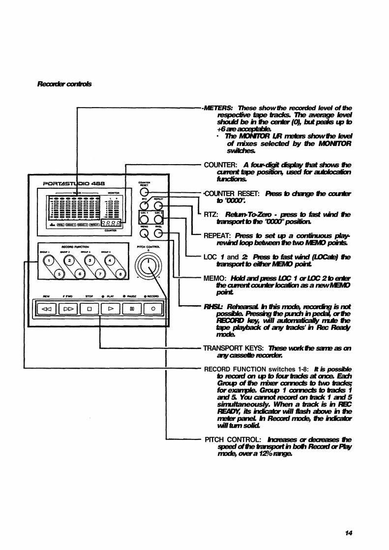
Recorder controls
-METERS: These show the recorded level of the respective tape tracks. The average level should be in the center (0), but peaks up to +6 are acceptable. • The MONITOR L/R meters show the level
of mixes selected by the MONITOR switches.
COUNTER: A four-digit display that shows the current tape position, used for autolocation functions.
•COUNTER RESET: Press to change the counter to "0000".
RTZ: Return-To-Zero - press to fast wind the transport to the "0000" position.
REPEAT: Press to set up a continuous play-rewind loop between the two MEMO points.
LOC 1 and 2: Press to fast wind (LOCate) the transport to either MEMO point.
MEMO: Hold and press LOC 1 or LOC 2 to enter the current counter location as a new MEMO point.
RHSL: Rehearsal. In this mode, recording is not possible. Pressing the punch in pedal, or the RECORD key, will automatically mute the tape playback of any tracks' in Rec Ready mode.
TRANSPORT KEYS: These work the same as on any cassette recorder.
RECORD FUNCTION switches 1-8: It is possible to record on up to four tracks at once. Each Group of the mixer connects to two tracks; for example. Group 1 connects to tracks 1 and 5. You cannot record on track 1 and 5 simultaneously. When a track is in REC READY, its indicator will flash above in the meter panel. In Record mode, the indicator will turn solid.
PITCH CONTROL: Increases or decreases the speed of the transport in both Record or Play mode, over a 12% range.
14
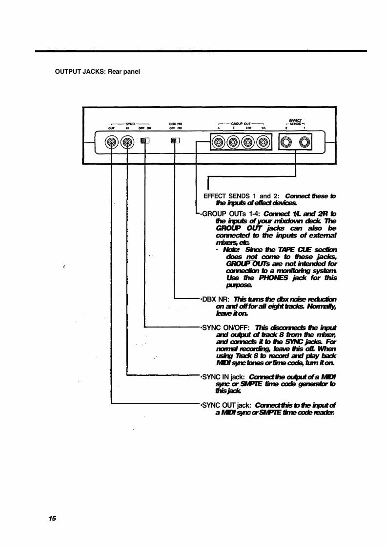
OUTPUT JACKS: Rear panel
EFFECT SENDS 1 and 2: Connect these to the inputs of effect devices.
-GROUP OUTs 1-4: Connect 1/L and 2/R to the inputs of your mixdown deck. The GROUP OUT jacks can also be connected to the inputs of external mixers, etc. • Note: Since the TAPE CUE section
does not come to these jacks, GROUP OUTs are not intended for connection to a monitoring system. Use the PHONES jack for this purpose.
•DBX NR: This turns the dbx noise reduction on and off for all eight tracks. Normally, leave it on.
•SYNC ON/OFF: This disconnects the input and output of track 8 from the mixer, and connects it to the SYNC jacks. For normal recording, leave this off. When using Track 8 to record and play back MIDI sync tones or time code, turn it on.
•SYNC IN jack: Connect the output of a MIDI sync or SMPTE time code generator to this jack.
•SYNC OUT jack: Connect this to the input of a MIDI sync or SMPTE time code reader.
15
Step-By-Step Operations Guide
Let's try the 488 mixer
Before connections
Input connections
Powering on
Headphone connection
Routing inputs
Panning
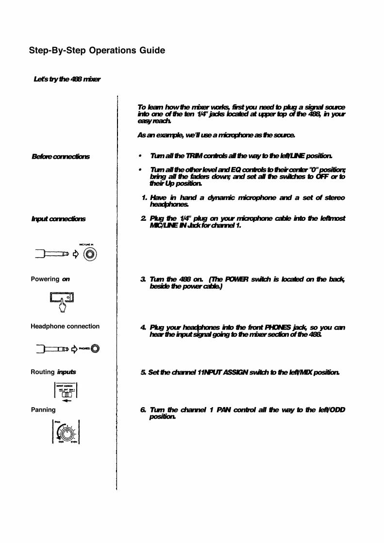
To learn how the mixer works, first you need to plug a signal source into one of the ten 1/4" jacks located at upper top of the 488, in your easy reach.
As an example, we'll use a microphone as the source.
• Turn all the TRIM controls all the way to the left/LINE position.
• Turn all the other level and EQ controls to their center "0" position; bring all the faders down; and set all the switches to OFF or to their Up position.
1. Have in hand a dynamic microphone and a set of stereo headphones.
2. Plug the 1/4" plug on your microphone cable into the leftmost MIC/LINE IN Jack for channel 1.
3. Turn the 488 on. (The POWER switch is located on the back, beside the power cable.)
4. Plug your headphones into the front PHONES jack, so you can hear the input signal going to the mixer section of the 488.
5. Set the channel 11NPUT ASSIGN switch to the left/MIX position.
6. Turn the channel 1 PAN control all the way to the left/ODD position.

Assigning to groups
Channel level
Group level
Monitor selection
Listening level
TRIM adjustment
17
7. Press the channel 1 ASSIGN "1/L-2/R" switch.
8. Raise the channel fader to "7" on the scale.
9. Raise the MASTER "1/L-2/R" fader to "7".
10. Press the MONITOR "GROUP 1" switch.
11. Turn the PHONES level control up to the 12 o'clock position.
12. While speaking into the mic, slowly turn the TRIM control in channel 1 to the right. You will hear your voice in the headphones.
When using a line level source {such as electronic instruments) instead of the mic, the TRIM does not need to be turned up very far, if at all.
How to record on track 1
Loading a cassette
Getting past the leader tape
Resetting the counter
Selecting tracks
Mic level adjustment
Beginning to record
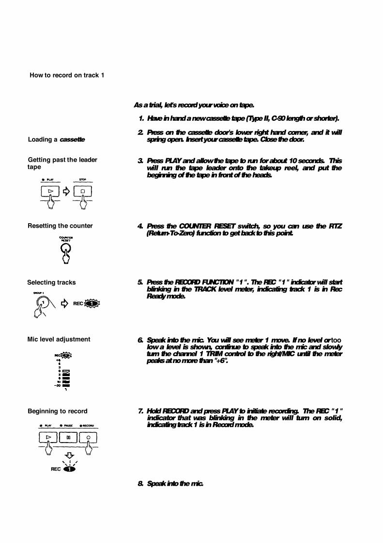
As a trial, let's record your voice on tape.
1. Have in hand a new cassette tape (Type II, C-90 length or shorter).
2. Press on the cassette door's lower right hand corner, and it will spring open. Insert your cassette tape. Close the door.
3. Press PLAY and allow the tape to run for about 10 seconds. This will run the tape leader onto the takeup reel, and put the beginning of the tape in front of the heads.
4. Press the COUNTER RESET switch, so you can use the RTZ (Return-To-Zero) function to get back to this point.
5. Press the RECORD FUNCTION "1". The REC "1" indicator will start blinking in the TRACK level meter, indicating track 1 is in Rec Ready mode.
6. Speak into the mic. You will see meter 1 move. If no level or too low a level is shown, continue to speak into the mic and slowly turn the channel 1 TRIM control to the right/MIC until the meter peaks at no more than "+6".
7. Hold RECORD and press PLAY to initiate recording. The REC "1" indicator that was blinking in the meter will turn on solid, indicating track 1 is in Record mode.
8. Speak into the mic.

Stopping to record
Putting track into "Safe"
9. Press STOP to stop the tape and terminate recording.
10. The REC "1" indicator in the meter should now be blinking as before. Press the RECORD FUNCTION "1" switch to turn that indicator off.
Track 1 playback through CUE MONITOR
Locating tape to 0000
Routing inputs
Routing tape signals to CUE
Monitor selection
CUE MASTER level adjustment
Stop in play
19
1. Press the RTZ key. The tape will rewind, automatically stopping at counter zero point
2. Set the channel 1 INPUT ASSIGN switch to the center OFF position.
3. Turn the channel's TAPE control all the way to the right/CUE position.
4. Press CUE in the MONITOR select switches, so you can hear the tape.
5. Press PLAY.
6. Slowly turn the CUE MASTER control to the right You will hear what you have recorded on track 1 in your headphones.
7. Press STOP to stop play.
Begin to play

How to make an overdub on track 2
Routing input
Panning
Assigning to group
Channel 1 level
Channel 2 level
Monitor selection
Locating tape to 0000
Record level adjustment (TRIM)
Overdubbing is recording one or more additional tracks on the same tape, while listening to previously recorded tracks using CUE.
Leave the microphone connected to the channel 1 input. There is no need to repatch it to channel 2 to record on track 2. You can continue to use channel 1 because the channel's ASSIGN makes it possible to send any mixer input to any track of the recorder.
1. Set the channel 1 INPUT ASSIGN switch to the left/MIX position.
2. Turn the channel 1 PAN control all the way to the right/EVEN position.
3. Check to see that the channel 1 ASSIGN 1/L-2/R switch is still on (down position).
4. Bring the channel 1 fader to 7.
5. Bring the MASTER 1/L-2/R fader to 7.
6. Press the MONITOR select switch GROUP 2 to turn it on. Press the GROUP 1 switch, turning it off (Up position).
7. Press the RTZ key, so the tape will rewind to the beginning of the track 1 recording.
8. Press the RECORD FUNCTION "2" switch. The REC 2 indicator will start blinking in the meter.
9. Speak into the mic to check to see meter 2 move. If no level or too low a level is shown, continue to speak into the mic and slowly turn the channel 1 TRIM control to the right until the meter peaks at no more than +6.
Track selection
20

Begin to record
Monitoring input/tape
Stop recording
Putting track into "Safe
10. Hold RECORD and press PLAY to initiate recording. The REC "2" indicator that was blinking will turn on solid, indicating track 2 is now being recorded.
11. You will hear track 1 play, together with the new signal going to track 2, in the headphones.
NOTE: Adjust only the TAPE control of channel 1 if you need to change the balance between the old and new tracks in your headphones. Leave the CHANNEL LEVEL and GROUP 2 MASTER alone, because they control the level being recorded.
12. Press STOP to stop recording.
13. The REC 2 indicator in the meter should now be blinking as before. Press the RECORD FUNCTION "2" switch to turn that indicator off.
How to record all other tracks
Tracks 3 to 8 can be recorded using almost the same procedure used for tracks 1 and 2. The differences are that the ASSIGN 3-4 switch is used for recording on tracks 3, 4. and 7 and 8 as selected by the RECORD FUNCTION switches, and the ASSIGN 1-2 switch is again used for
recording tracks 5 and 6 as selected by the RECORD FUNCTION switches. The PAN controls should also be rotated to ODD or EVEN depending on the track numbers. See table below.
Track TRK1 TRK2 TRK3 TRK4 TRK5 TRK6 TRK7 TRK8
Group to be used GRP1 GRP2 GRP3 GRP4 GRP1 GRP2 GRP3 GRP4
Channel setting: Pan ODD EVEN ODD EVEN ODD EVEN ODD EVEN
: Assign 1-2 3-4 1-2 3-4
Record Function 1 2 3 4 5 6. 7 8
21

How to record many sources onto a single track How to record multiple tracks simultaneously
In the first example we recorded one microphone onto one track at a time. However, if you want to record more than one source onto a track at once, set the ASSIGN and PAN controls of each channel to the same setting, for example:
If you want to record more than one track at a time, you simply decide which instruments you want to record on which tracks, and use the channel ASSIGN and PAN controls to send them there:
-As desired
These mixer channels are being sent to Group 1, for recording on either Track 1 or Track 5.
In this example, press RECORD FUNCTION 1 to record on track 1 all instruments plugged into inputs 1-4.
This mixer channel is being sent to Group 1, for record¬ ing on either Track 1 or Track 5.
This mixer channel is being sent to Group 4, for record¬ ing on either Track 4 or Track 8.
Restrictions: The 488's mixer section only has 4 output groups, so 4 tracks is the maximum number that can be recorded at one time. Also, two tracks that share the same group cannot be recorded simultaneously. For example, you cant record on track 4 and track 8 at the same time.
Monitoring is done by pressing the MONITOR switches corresponding to the GROUPs you are recording (plus CUE if you need to hear tape tracks or MIDI virtual tracks).
Recording is the same procedure as for one track, except that you put multiple tracks into REC READY mode. In the example above, press RECORD FUNCTION 1 and 4 to record on tracks 1 and 4 simultaneously.

How to mix down
Connections
Master level
Monitor source
Routing inputs
Routing tape signals
Assigning to groups
When the 8 tracks are all recorded, the final step is mixing them into a standard stereo format. This procedure is known as Remixing or Mixing down. During this procedure the tracks are blended together and balanced to create the desired sound.
1. Connect the GROUP OUT 1/L jack of the 488 to the left line input of the mixdown deck, and the GROUP OUT 2/R jack to the right line input.
2. Raise the 1/L-2/R MASTER fader to the shaded area between 7
and 8.
3. Press the GROUP 1 and GROUP 2 MONITOR selector switches. All other MONITOR switches must be UP.
4. Set all the INPUT ASSIGN switches on the input channels to the center OFF position.
5. Turn the TAPE controls of all eight channels fully counterclockwise to the MIX position.
6. Press all the 1/L-2/R ASSIGN switches.
23
Playback level
Review
Record level
7. Press PLAY and, while listening to the tape play, use the channel faders to set each track's relative level for the desired balance. The channel 1 fader is being fed with track 1, the channel 2 fader with track 2, the channel 3 fader with track 3, and so on.
8. Adjust the PAN controls to set each track's left-to'-right position for the desired stereo image. You may also want to use the EQ controls to adjust the individual tracks for the desired tonality. (For using effects, see page 33.)
9. When the signal balance, level, and tonality sound right, rewind the tape, and press PLAY again to check the result.
10. Rewind the Multitrack tape again. Put a blank tape in the mixdown deck and let it play for 10 to 15 seconds, then stop it and reset the mixdown deck's counter to zero.
11. Press PLAY on the 488.
12. Put the mixdown deck into its "Record Ready" mode, and adjust its input level controls for the desired record level.
13. Rewind the multitrack tape to the beginning of the recording.
14. Put the mixdown deck into Record mode then press PLAY on the 488.
15. When the recording is done, stop both machines, rewind the mixdown tape and listen to it.
If the mixdown tape does not sound right, make the necessary corrections and re-do from the beginning.
24
Using Memory Location Points
Loading MEMO points
MEM0 1
MEMO 2
Establishing new MEMOs
Recalculation of MEMOs
Checking MEMO points
Erasing
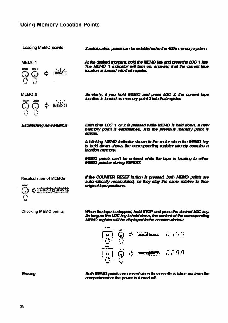
2 autolocation points can be established in the 488's memory system.
At the desired moment, hold the MEMO key and press the LOC 1 key. The MEMO 1 indicator will turn on, showing that the current tape location is loaded into that register.
Similarly, if you hold MEMO and press LOC 2, the current tape location is loaded as memory point 2 into that register.
Each time LOC 1 or 2 is pressed while MEMO is held down, a new memory point is established, and the previous memory point is erased.
A blinking MEMO indicator shown in the meter when the MEMO key is held down shows the corresponding register already contains a location memory.
MEMO points can't be entered while the tape is locating to either MEMO point or during REPEAT.
If the COUNTER RESET button is pressed, both MEMO points are automatically recalculated, so they stay the same relative to their original tape positions.
When the tape is stopped, hold STOP and press the desired LOC key. As long as the LOC key is held down, the content of the corresponding MEMO register will be displayed in the counter window.
Both MEMO points are erased when the cassette is taken out from the compartment or the power is turned off.
25

Locating the tape
To 0000
To MEMO 1
To MEMO 2
Auto play
RTZ
Auto pause
Press the RTZ key to fast wind the tape to the counter zero point.
Press the LOC 1 key to fast wind the tape to the MEMO 1 point.
Press the LOC 2 key to fast wind the tape to the MEMO 2 point.
If PLAY is pressed after RTZ, LOC 1 or LOC 2, the tape will automatically start playing when the location point is reached.
If PAUSE is pressed after RTZ, LOC 1 or LOC 2, the tape will enter Pause mode after the search operation.
26
Repeat Play
Operating procedure
To interrupt REPEAT sequence
Notes
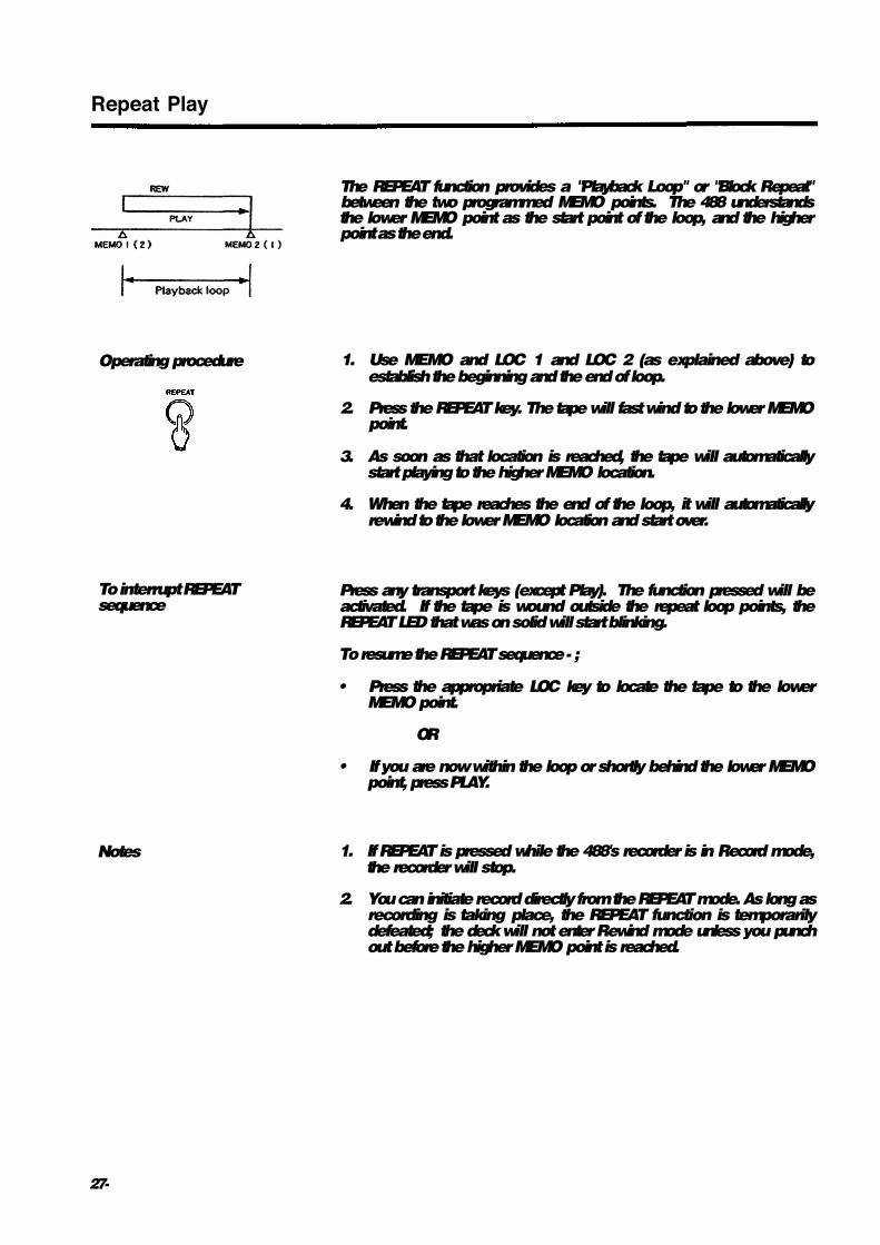
The REPEAT function provides a "Playback Loop" or "Block Repeat" between the two programmed MEMO points. The 488 understands the lower MEMO point as the start point of the loop, and the higher point as the end.
1. Use MEMO and LOC 1 and LOC 2 (as explained above) to establish the beginning and the end of loop.
2. Press the REPEAT key. The tape will fast wind to the lower MEMO point.
3. As soon as that location is reached, the tape will automatically start playing to the higher MEMO location.
4. When the tape reaches the end of the loop, it will automatically rewind to the lower MEMO location and start over.
Press any transport keys (except Play). The function pressed will be activated. If the tape is wound outside the repeat loop points, the REPEAT LED that was on solid will start blinking.
To resume the REPEAT sequence - ;
• Press the appropriate LOC key to locate the tape to the lower MEMO point.
OR
• If you are now within the loop or shortly behind the lower MEMO point, press PLAY.
1. If REPEAT is pressed while the 488's recorder is in Record mode, the recorder will stop.
2. You can initiate record directly from the REPEAT mode. As long as recording is taking place, the REPEAT function is temporarily defeated; the deck will not enter Rewind mode unless you punch out before the higher MEMO point is reached.
27-

PUNCH-IN or INSERT Recording
"Punching in" or "insert recording" is when you record over a small section of a previously recorded track in order to fix a mistake or improve a performance, while keeping the rest of the track as before. The mixer settings should be exactly the same as they were during the original recording.
The 488 can manually punch-in with the RECORD (•) key, the RECORD FUNCTION switches, or the optional RC-30P footswitch.
REHEARSE function
This function is activated by pressing the RHSL switch. Its LED will start blinking. During a rehearsal, what you hear in the monitor mix and read on the TRACK level meters will be the same as during recording, but signal won't be recorded on tape. The playback is simply muted while RECORD is on.
You can rehearse your punch-in as many times as you need without affecting the existing recording at all. When you are sure of your performance and ready to actually record the insert, turn off the RHSL LED by pressing the switch again.
Punch-in/out procedure
Preliminary
The 488 offers 3 ways to initiate the punch-in. The first is with the transport RECORD key, the second with the track RECORD FUNCTION switch, and the third with the remote foot switch.
In the following, we'll use track 2 as the punch-in track as an example.
1. As the punch-in track is track 2 in our example, your input needs to be assigned to GROUP 2. To do so, turn the PAN control in the channel which your source instrument is plugged into, all the way to the right (EVEN), and press the channel's 1/L-2/R ASSIGN switch.
Keep all the other channels' ASSIGN switches off.
2. To hear the tape, the CUE signal path is used. So, turn each TAPE control to the right of center (CUE side) and press the CUE switch in the MONITOR switch rack.
3. To hear the instrument press the MONITOR GROUP 2 switch.
4. Press PLAY to play the tape, then adjust the CUE MASTER control until the MONITOR level meters peak at about 0 to +3, and adjust the PHONES control for the desired listening level of the headphones.
5. Play the instrument. You'll hear it together with the tape signals in the headphones. Stopping the tape will allow you to hear only the instrument.
28
Selecting in and out points
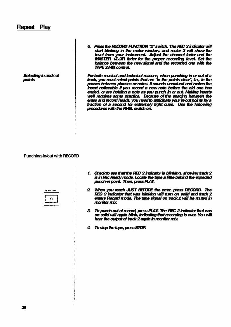
6. Press the RECORD FUNCTION "2" switch. The REC 2 indicator will start blinking in the meter window, and meter 2 will show the level from your instrument. Adjust the channel fader and the MASTER 1/L-2/R fader for the proper recording level. Set the balance between the new signal and the recorded one with the TAPE 2 MIX control.
For both musical and technical reasons, when punching in or out of a track, you must select points that are "in the points clear", i.e., in the pauses between phrases or notes. It sounds unnatural and makes the insert noticeable if you record a new note before the old one has ended, or are holding a note as you punch in or out. Making inserts well requires some practice. Because of the spacing between the erase and record heads, you need to anticipate your in/out points by a fraction of a second for extremely tight cues. Use the following procedures with the RHSL switch on.
Punching-in/out with RECORD
1. Check to see that the REC 2 indicator is blinking, showing track 2 is in Rec Ready mode. Locate the tape a little behind the expected punch-in point. Then, press PLAY.
2. When you reach JUST BEFORE the error, press RECORD. The REC 2 indicator that was blinking will turn on solid and track 2 enters Record mode. The tape signal on track 2 will be muted in monitor mix.
3. To punch-out of record, press PLAY. The REC 2 indicator that was on solid will again blink, indicating that recording is over. You will hear the output of track 2 again in monitor mix.
4. To stop the tape, press STOP.
29
Repeat Play
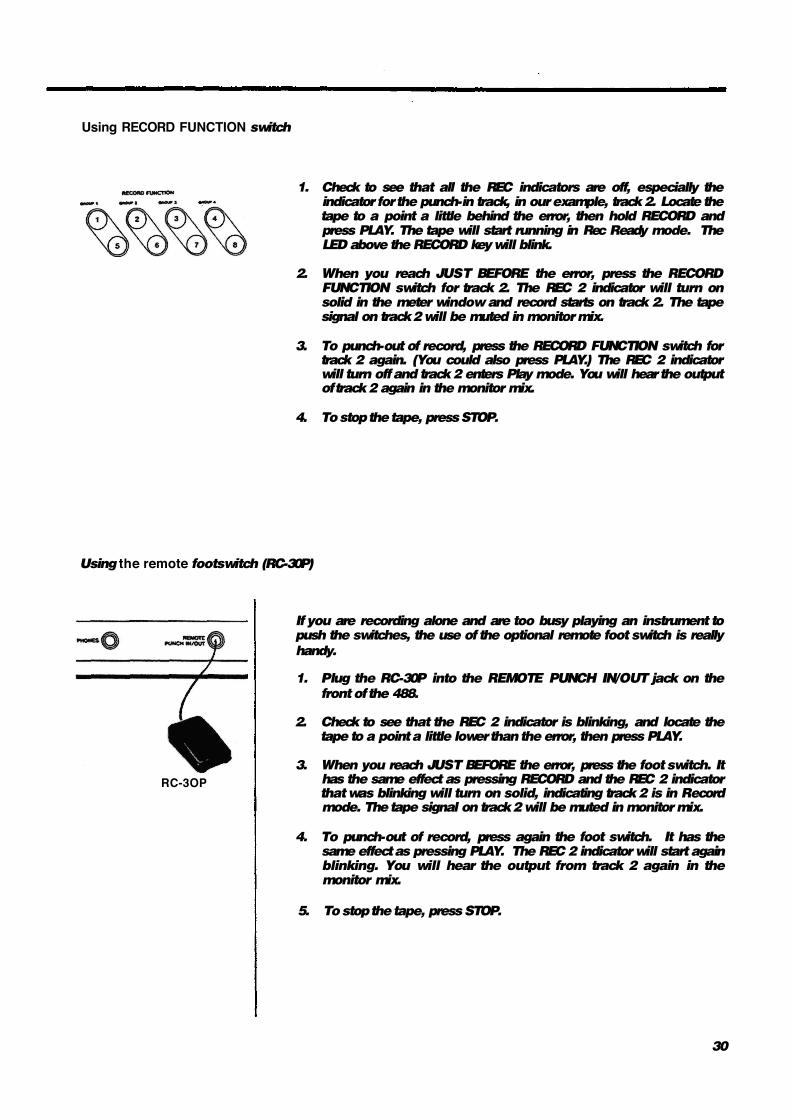
Using RECORD FUNCTION switch
1. Check to see that all the REC indicators are off, especially the indicator for the punch-in track, in our example, track 2. Locate the tape to a point a little behind the error, then hold RECORD and press PLAY. The tape will start running in Rec Ready mode. The LED above the RECORD key will blink.
2. When you reach JUST BEFORE the error, press the RECORD FUNCTION switch for track 2. The REC 2 indicator will turn on solid in the meter window and record starts on track 2. The tape signal on track 2 will be muted in monitor mix.
3. To punch-out of record, press the RECORD FUNCTION switch for track 2 again. (You could also press PLAY.) The REC 2 indicator will turn off and track 2 enters Play mode. You will hear the output of track 2 again in the monitor mix.
4. To stop the tape, press STOP.
Using the remote footswitch (RC-30P)
RC-3OP
If you are recording alone and are too busy playing an instrument to push the switches, the use of the optional remote foot switch is really
handy. •
1. Plug the RC-30P into the REMOTE PUNCH IN/OUT jack on the
front of the 488.
2. Check to see that the REC 2 indicator is blinking, and locate the tape to a point a little lower than the error, then press PLAY.
3. When you reach JUST BEFORE the error, press the foot switch. It has the same effect as pressing RECORD and the REC 2 indicator that was blinking will turn on solid, indicating track 2 is in Record mode. The tape signal on track 2 will be muted in monitor mix.
4. To punch-out of record, press again the foot switch. It has the same effect as pressing PLAY. The REC 2 indicator will start again blinking. You will hear the output from track 2 again in the monitor mix.
5. To stop the tape, press STOP.
30

Bouncing Tracks (Ping-Pong)
The recording capability of the PORTASTUDIO 488 is not limited to eight tracks. You can "bounce" or combine tracks you have recorded to an empty track, and then replace the original tracks with new material. A bounce is like a mixdown, except you are recording to one of the tracks of the 488 instead to an external recorder.
The following diagrams depict the process.
Bouncing tracks 1-4 onto track 8
Tracks 1-4 available for recording new parts
Bouncing new tracks 1-4 onto track 7
Also, while you are bouncing, you can add live sources to the combination of the prerecorded tracks, by setting both the INPUT SELECT switch and TAPE controls to MIX position. (See the signal flowing chart on page 7.)
Ping-pong procedure
In this example, we will combine material from tracks 1-4 onto track 8.
1. Set all the channels' INPUT ASSIGN switches to the center/OFF position.
2. Turn the TAPE control on channels 1-4 all the way to the left/MIX.
3. Turn the channels' PAN controls all the way to the right/EVEN.
4. Press the ASSIGN "3-4" switch on channels 1-4.
5. Raise the MASTER "3-4" fader to 7.
6. Press the MONITOR "GROUP 4" switch, and make sure all other MONITOR switches (CUE, GROUP 1-3) are OFF.
7. Press the RECORD FUNCTION switch for track 8. The REC 8 indicator will start blinking in the meter window, indicating the track is in Rec Ready mode.
31

8. Press PLAY. The tape will start playing.
9. Use channel faders 1 through 4 to make any necessary level adjustments. You may want to repeat this step several times to get the balance correct
10. When the balance is right and the level is peaking at no more than +6 on the TRACK 8 meter, stop and rewind the tape to the beginning of the track.
11. Hold RECORD and press PLAY. The REC 8 indicator that was blinking will turn on solid and track 8 will record a copy of what is on tracks 1-4.
12. You'll hear the mix being recorded on track 8 in the headphones.
13. Once the recording is done, press STOP.
14. The REC 8 indicator will now be blinking as before. Turn that off by pressing the RECORD FUNCTION switch for track 8.
Ping-pong in stereo procedure
It is also common to bounce six channels to two tracks (for example, tracks 1-6 to 7 & 8) as a stereo pair.
1. Set all the channels' INPUT ASSIGN switches to the center/OFF position.
2. Simply arrange the PAN controls for channels 1-6 as disired -some left, some right, some in the middle.
3. Press the RECORD FUNCTION switch for both tracks 7 and 8.
4. Continue as the above example.
32

Using Effects with the PORTASTUDIO 488
Effects and signal processing is one of the areas where you can really start to have fun customizing your, sound, and develop your own unique recording style- Because there are so many possibilities, it also can be confusing. There are many different effect units on the market all with different controls, types of inputs and outputs, and other characteristics. Read the manual of your effects device, and the following sections to get the complete story of what's possible for your particular situation.
1. In-line processing: The processing that's easiest to understand doesn't involve the 488 directly at all. You can plug your instrument directly into the input of the effect device, and plug the output of the device directly into a line input of the 488. The whole signal gets processed (flanged, doubled, limited, delayed etc.), and only one instrument can use that processor. Effect pedals for guitar are typically used this way. To get a mix of processed ("wet") and original ("dry") signal, the unit must have its own "MIX" or "BALANCE" control.
2. Send/return mix processing: This is the most common method of effect processing, especially for reverb and delay. It allows a number of different channels to use the same effect, while allowing you to control how much effect is mixed with each channel. Each of the lower 8 mixer channels can send signals to the EFFECT SEND 1 or 2 outputs on the upper top panel. These outputs can then be connected to the input of effect devices. The processed signals from the devices come back into the mix via the STEREO INPUTS. Finally, the effect is mixed onto one of the groups with the ASSIGN switch on the stereo channels (9-10 and 11-12). This whole path- from the EFFECT SENDS to the reverb and back into STEREO INPUTS -- is called an effects loop. The EFFECT SENDS and 2 MASTERS control how much signal goes to the reverb unit; the LEVEL control on the stereo channels determine how much returns from the reverb unit. In this method, the stereo inputs function as "effect returns".
Setting Effect Send Levels
The goal is not to distort the device, while staying above the noise that effect units generate. To get the best signal-to-noise from most effects units, you should send it as strong a signal as you can. With a properly set input signal in the 488, the channel EFFECT Send set to either 3 o'clock (EFFECT 1 feed) or 9 o'clock (EFFECT 2 feed), and the EFFECT MASTERS at about 2 o'clock, you should get a fairly loud signal from the EFFECT SEND jacks.
If your effects device has an input level control of its own, it should be set so the meter or signal light of the effects device is just under the overload point on peak signals. When you want to hear less effect overall, turn down the return LEVEL control, not the EFFECT MASTERS.
Setting the output level of effect devices
If the effect send level has been set properly, in most cases the output level of the effect unit should be set as high as possible without clipping (distorting) the STEREO INPUTS of the 488, but low enough so that you have a reasonable range of control. If you can get the effect sound you want with the return LEVEL control in the 12 to 2 o'clock range, you're in the ballpark. If, on the other hand, very small settings of the Effects Return still give you a mix drowning in effects, turn down the output level of your effect device.
Some effect units have rear panel switches setting input and output level ranges between "+4" and "-20 dB". In this case, try setting the input to -20 (high sensitivity) and the output to +4 (full output level).
Setting the mix/balance control on effect devices
When it's being used in a send-return mix, set the mix/balance of your effect device all the way to "wet" or full processing with no direct original signal. In send/receive processing, the dry signal goes down the 488's CHANNEL FADER to be mixed with the effect return signal on a group master. Therefore, you don't need any "dry" signal coming to the effects return. The mix/balance control is set toward "dry" only when you're using the effects device as an in-line processor.
33

How to connect your effects devices
There is no absolute "right" or "wrong" way to do this-there are several ways, each with its own consequences.
This is the most common method. EFF 1 feeds a reverb unit, which has a synthesized stereo output patched into STEREO INPUTS 9-10. EFF 2 feeds a chorus device with a stereo output patched into STEREO INPUTS 11-12.
Mono returns: A special feature of the STEREO INPUTS allows continuously variable control between left and right if desired: a mono effect connected to L/MONO will go to both the "9-10" and "11-12" LEVEL controls if nothing is plugged into the R jack. In this mono mode, the "9-10" LEVEL control adjusts how loud the mono effect will be on the Left side (Odd-numbered groups), and the "11-12" LEVEL controls how loud it will be on the Right side (Even-numbered groups). You can vary the two controls to send signal anywhere between the two groups, similar to using a PAN control.
Patching effects to an input channel: There's no law that says the output of an effects device must be plugged into a STEREO INPUT, either. They can also be plugged into LINE INs just like any other source, if you are cautious about one thing: make sure the EFFECT controls of those channels are set to the center (off) position. Otherwise, you will be sending the output of the effect device back to itself, which is a kind of feedback. If the effect device is a digital delay, feedback has the same effect as a regeneration (number of echoes) control. An advantage of returning effects to a main channel is that you can EQ the effect return.
To record reverb onto a track: Simply assign the return to the proper GROUP for the track being recorded and adjust the controls for the sound you want. Remember the stereo effects must be recorded onto two tracks, or mixed to mono.
To hear reverb in the headphones but not record the reverb: Assign the effect return channel(s) to a group that's not being recorded (for example, assign it to group 4 while you're recording on tracks 1 and 2). By pressing the Group 4 switch in the monitor and turning up its LEVEL control, you'll hear the reverb, but the recording will be "dry".
An alternate method, which leaves all four groups free but offers less control, is: 1. Patch the output of the effect device to
any LINE IN 5 through 8. 2. Switch the INPUT ASSIGN of this channel
to the right (CUE). The effect return can now be heard in the CUE mix. Since all level controls of the channel are bypassed, you will have to make output level adjustments on the effect device itself.
34

Recording with TAPE SYNC
Connections
Meter 8 function during SYNC
The 488 has a SYNC feature that allows you to have your electronic instruments play in sync with the tape. MIDI clocks are themselves a computer type digital language and cannot be recorded on analog tape ; it is necessary to convert them to recordable FSK (Frequency Shift Keying) signals using an appropriate converter, such as the MTS-30.
The MTS-30 is not a mere MIDI-FSK converter but translates MIDI clocks into a FSK sync signal containing score "bar" information or "Song Position Pointer", allowing the associated MIDI equipment to stay in sync and follow the tape no matter where you move the tape within a given song. The maximum stability or resolution of the synchronization is ensured by a TEAC-exclusive error correction circuit in the MTS-30.
The 488 has dedicated jacks for SYNC tones and can directly record and read them without passing through the 488 mixer. A direct connection between the sync tone generator and the 488 recorder ensures that FSK won't accidentally leak into the audio, and unwanted audio won't leak into the FSK tone.
1. Locate the SYNC ON/OFF switch to the 488's rear panel and set it to ON. This defeats the dbx encode/decode for track 8 only.
2. Connect the TAPE OUT of the MTS-30 to the SYNC IN of the 488, and the SYNC OUT of the 488 to the TAPE IN of the MTS-30.
When the SYNC ON/OFF switch is set to ON, the level meter for track 8 is switched to the SYNC IN jack and is active only when track 8 is in Record or Record ready modes. In playback, the meter 8 will not display.
488
35
488 MIXER
Input Section
The input section of the 488 is made up of input jacks, input level controls (on channels 1 and 2 only) and switches that determine where the input signal is sent.
Channels 1-2 differ from channels 3-8 in construction.
[Channels 1-2]
1. MIC/LINE IN jack: This 1/4" jack accepts unbalanced signals ranging from -50 dBV (0. 3 mV) to -10 dBV (0.3 V), depending on the setting of the TRIM control (#3).
3. TRIM control: This sets how much pream-plification level there is on the MIC/LINE INputs (#1). When TRIM is turned all the way to the left (LINE position), the preamplifier gain is low, allowing the jack to accept line level sources such as electronic instruments or other -10 dBV output audio equipment. As you turn TRIM up, the preamplifier gain increases, and when you turn TRIM full clockwise (MIC position), the nominal input sensitivity of the jack increases to -50 dBV (0.3 mV).
4. INPUT ASSIGN switch: This controls where the MIC/LINE jack signal is sent:
MIX: signal is sent through the mixer channel controls.
OFF: stops the signal here. GRP: sends signal directly to the correspon¬
ding MASTER faders, directly, without passing through the mixer channel controls.
[Channels 3-8]
2. LINE IN jack: This 1/4" jack is for connection of unbalanced line level signals. The nominal input sensitivity is -10 dBV (0.3 V). The LINE input has no trim control and directly reaches the INPUT ASSIGN switch.
4. INPUT ASSIGN switch: This controls where the LINE jack signal is sent
MIX:for sending signal through the mixer channel controls.
OFF :turns the signal off. GRP (channels 3 and 4):
sends signal to MASTER fader "3-4", directly, bypassing the channel controls.

CUE (channels 5-8): for sending signals directly to the CUE MASTER control, for monitoring in headphones without recording.
Tape Monitor Section
In this section of the 488, you control the playback levels of previously recorded tracks. You can send signal to the CUE section (for hearing during overdubs) or to the MIXer channel (for mixdown or bouncing tracks).
5. TAPE control: This is a combination "where to" and "how much" control. It gets its signal only from the tape and controls how much of it will go to the mixer channel or to the headphones via the CUE MASTER control (#19) and the MONITOR "CUE" switch.
MIX: when the control is turned to the left of center, the playback signal from the corresponding track* is sent through the mixer channel, so the tape signal can be controlled by the channel fader, EQ, and assigned to group outputs.
If the channel's INPUT ASSIGN switch (#4) is set to the left/MIX position, the input signal will also be sent through the channel controls. To get a balance between Input and Tape playback, turn the TAPE control.
CUE: when the control is turned to the right of center, it sends the track playback signal to the CUE MASTER control (#19). Adjusting how far you turn each control sets the level of each track in the CUE mix.
* The TAPE control in channel 1 gets its signal from track 1, the control in channel 2 from track 2, the control in channel 3 from track 3, and so on.
Channel Controls
This section of the 488 is made up of equalizers and input faders and gets its signal from the MIX position of both the INPUT ASSIGN switch and the TAPE control.
The equalizer or EQ is the circuitry that allows you to adjust the tonality of the signal going through the input channel. The EQ in the 488 is a two-band type: HIGH and LOW.
6. EQ HIGH: This controls the tonality of the high or "treble" frequencies. Turn it to the right to boost the high frequency content of the signal and emphasize its brilliance or brightness. Turning it to the left cuts the high frequency content, if the signal sounds too harsh or shrill. The EQ shelving point is 10 kHz.
7. EQ LOW: Turned to the right, the control boosts the bass frequencies and the signal will sound relatively heavy. Turn the control to the left to cut bass and make the signal sound thinner. The EQ shelving point is 100 Hz.
8. Channel Fader: This linear control varies the level feeding the "Group Master" section.
The nominal setting position is between 7-8 (shaded area).
Channel Assignment Section
In this section you'll send (assign) the signal coming from the channel faders to any of the four master group outputs, and control the amount of signal between odd/even (or Left/ Right) groups.
The 488 mixer has only four group outputs while the incorporated recorder has eight tracks. You can record a maximum of 4 tracks at a time. Group 1 can feed either track 1 or 5, Group 2 feeds track 2 or 6, Group 3 feeds track 3 or 7, and Group 4 feeds track 4 or 8. The diagram below depicts how a channel signal goes through the mixer controls to the tracks.
37

lf the 'PAN is set towards the center, it is possible to send to multiple groups at once.
9. PAN control: This control allows you to create stereo mixes by sending the signal from the channel fader in continuously variable degrees to the odd or even groups (or to the left or right sides of the stereo mix at mixdown time).
10. ASSIGN switch: This routes signals coming from the PAN control to the corresponding MASTER faders, for recording onto multitracks.
Effect Send Section
Through this section of the 488, channel signals are sent to external devices, primarily effects processors (such as reverb units).
11. EFFECT control: This is a combination "where to" and "how much" control. It gets its signal from a point just after the channel fader and routes the corresponding channel signal to one of the two Effect Send Masters. In the center (12 o'clock) position, the effect send is OFF. Turn the control to the left of center to send signal to EFFECT 1, or to the right of center to send signal to EFFECT 2. The further you turn it either way, the louder it will be - if it's turned all the way to the left, it's at full volume to EFFECT 1 ; and if it's turned all the way to the right, it's at full volume to EFFECT 2.
12. EFFECTS SEND MASTERS: These are the master volume controls for the EFF 1 and EFF 2 mixes. They get their signal from the EFFECT controls in the channels. The signal then goes to the EFFECT SENDS 1 and 2 jacks on the back panel. Adjust the EFFECT SEND MASTERS until you have the correct
level feeding your external effects device. See p.33, "Setting Effects Send Levels".
13. EFFECT SENDS jacks: These are the outputs from the EFFECT SEND mixes of the 488. Signal comes here directly from the EFFECT SEND MASTERS level controls. They are typically connected to the inputs of external devices such as reverbs, digital delays, etc. (After the signals are processed, they are usually returned to the 488 via STEREO INPUTS on channels 9-10 and 11-12. A mono return may also be connected to any LINE IN jack on the channels 1 thru 8.) The EFFECT SENDS may also be used to feed a separate monitor.
Stereo Inputs Section
This section of the 488 includes two stereo signal paths which are equivalent to four additional inputs. You can use these inputs as EFFECT RETURNS:
14. STEREO INPUTS jacks: These jacks are the 3-conductor stereo (TRS) type. You can connect the outputs of your effects devices to these jacks, but they can be used for any line level input if desired. The nominal input level is-10 dBV (0.3 V).
Thanks to their special design, the STEREO INPUTS of the 488 have various functions:
Two Stereo Pairs (using insertion cables): By using a special cable (sometimes called an "insert" or "stereo splitter" cable, such as the TASCAM PW-2Y or PW-4Y), each STEREO INPUT jack can return two signals (left and right) from a stereo unit. The cable has a 3-conductor stereo 1/4" plug on one end, and at the other end splits into two cables, each with 2-conductor (mono) 1/4" plug. Plug the 3-conductor (tip-ring-sleeve) end into the STEREO INPUT of the 488, and the two mono plugs into the Left and Right outputs of the effect device or synthesizer.
NOTE: On the 9/10 stereo input, the tip signal is sent to the left (Groups 1 and 3), and ring to the right (Groups 2 and 4). On the 11/12 input the signals are reversed (tip to the right ring to the left).
Single Stereo Pair (using separate mono cables): If you only have standard mono cables, plug the left output of the unit into the 9/10 input of the 488 (also labeled "L/MONO"). Patch the right output of the unit
38
:Using Effects with the PORTASTUDIO 488

into the 11/12 input of the 488 (also labeled •R"). In this case, the 9/10 LEVEL controls the volume of the left (1-3) side, and the 11/12 LEVEL controls the volume of the right (2-4) side; use both LEVEL controls for the desired stereo balance.
Mono feature: If you have a mono-output device that you want to return to the center of the mix, connect that device to STEREO INPUTS "L/MONO" jack, making sure the R jack is empty. In this condition, the signal will "normal" to both LEVEL controls. By
adjusting the two LEVEL controls separately, you can send signal in varying degrees to the left, right, or center of the mix similar to using a pan pot.
NOTE: If you're feeding a stereo signal to the L/MONO jack, but have nothing in the R jack, make sure that the LEVEL control on the 11-12 channel is turned down all the way, otherwise the stereo picture will become more mono since the channel 11-12 LEVEL control will feed some of the left signal to the right side.
Special mono adapter plug: If you want to convert a Stereo Effect Return to mono operation that will feed the center of the mix but only use one control, wire a cable with a TRS (stereo) plug with the Tip and Ring both
connected to the signal lead from the effect device as shown. It is possible to have two mono effect returns feeding the center of the mix if two of these plugs are used,
To MONO OUTPUT of
Effects Devices
To a STEREO INPUTS Jack
39

15. ASSIGN switch: This routes signals coming from the LEVEL control (#16) to the corresponding MASTER faders, for recording onto multitrack.
When using TRS plugs, each switch sends signals separately to two Groups at once. In mono operation, each switch sends only to one Group (Ch.9/10 to 1 or 3, Ch.11/12 to 2 or 4) at a time.
16. LEVEL control: This rotary control varies the level feeding the "Group Master" Section.
The nominal setting position is about "2 o'clock".
Group Master Section
This section of the 488 gets its signal from the individual channels and is made up of two MASTER faders and four GROUP OUT jacks.
17. MASTER faders: These faders adjust the output levels of the groups. They get their signal from the ASSIGN switches in the channels. They send signal to the four GROUP OUT jacks on the back panel, to the MONITOR GROUP 1-4 switches, and to the multitrack recorder. The left fader controls the output level of groups 1 and 2, and is labeled "L/R" because during MIXDOWN the GROUP OUT 1/L and 2/R jacks normally feed the stereo two-track recorder. The right fader controls the output level of Groups 3 and 4.
18. GROUP OUT Jacks: These jacks are the line-level outputs from the four GROUP MASTER faders. The 1/L and 2/R jacks are typically connected to your two-track mixdown recorder at MIXDOWN. Another use of the GROUP OUT jacks is when you want to send the mixer outputs of the 488 to the sub inputs of a larger mixer.
Monitor Section
In this section of the 488, you'll control what and how much you hear in your headphones.
19. CUE MASTER control: This gets its signal from tape via the CUE side of the TAPE control in channels 1-8. It can also receive signals fed into channels 5-8 if their INPUT ASSIGN switch is in the CUE position.
The CUE MASTER mix is sent to the MONITOR "CUE" switch, then to the PHONES jack.
20. MONITOR (headphones) selector switch: What you'll hear in the headphones is controlled by this group of switches.
GROUP 1-4: sends each group mix to the headphones from a point after the MASTER faders, allowing you to hear what is going to tape during recording.
CUE: selects signals from the CUE MASTER control (#19 above). This position is typically used to listen to the previously recorded track (or tracks) during overdubs.
CUE should always be turned OFF during mixdown or while bouncing tracks. Press only GROUP 1 and 2 during mixdown. Press only the GROUP(s) actually being recorded through during a bounce.
Note also: Groups 1 and 3 are always sent to the left side of the headphone mix, and groups 2 and 4 are always sent to the right side. When only odd-numbered or even-numbered groups are selected, that mix is heard in center mono, as follows:
• GROUP 1/3 switches pressed (switches 2/4 released) - Group mix 1/3 is heard in the center.
• GROUP 1 and 2 and/or 3 and 4 switches pressed - Group mixes 1 and 3 feed the left side, and Group mixes 2 and 4 feed the right side.
• GROUP 2/4 switches pressed (switches 1/3 released) - Group mix 2/4 is heard in the center.
• CUE monitor mix is always monophonic, in the center.
21. PHONES control: This affects signal from the MONITOR selector switch and sets the level you'll hear in the headphones.
22. PHONES jack: Connect any stereo head¬ phones (with a 1/4" stereo TRS 3-conductor plug) to this jack.
40
488 RECORDER
Cassette Loading and dbx System
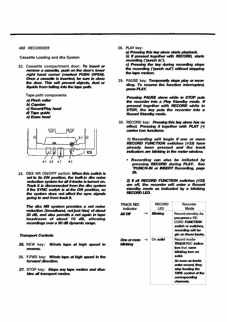
23. Cassette compartment door: To insert or remove a cassette, push on the door's lower right hand corner (marked PUSH OPEN). Once a cassette is inserted, be sure to close the door. This will prevent objects, dust or liquids from falling into the tape path.
Tape path components a) Pinch roller b) Capstan c) Record/Play head d) Tape guide e) Erase head
24. DBX NR ON/OFF switch: When this switch is set to its ON position, the built-in dbx noise reduction system for all 8 tracks is turned on. Track 8 is disconnected from the dbx system if the SYNC switch is at the ON position, so the system does not affect the sync signals going to and from track 8.
The dbx NR system provides a net noise reduction (broadband, not just hiss) of about 30 dB, and also permits a net again in tape headroom of about 10 dB, allowing recordings over a 90 dB dynamic range.
Transport Controls
25. REW key: Winds tape at high speed in
reverse.
26. F.FWD key: Winds tape at high speed in the forward direction.
27. STOP key: Stops any tape motion and disa-bles all transport modes.
28. PLAY key: a) Pressing this key alone starts playback. b) If pressed together with RECORD, starts recording ("punch in"). c) Pressing the key during recording stops the recording ("punch out") without stopping the tape motion.
29. PAUSE key: Temporarily stops play or recor-ding. To resume the function interrupted, press PLAY.
Pressing PAUSE alone while in STOP puts the recorder into a Play Standby mode. If pressed together with RECORD while in STOP, the key puts the recorder into a Record Standby mode.
30. RECORD key: Pressing this key alone has no effect. Pressing it together with PLAY (•) carries two functions:
1) Recording will begin if one or more RECORD FUNCTION switches (#33) have already been pressed and the track indicators are blinking in the meter window.
• Recording can also be initiated by pressing RECORD during PLAY. See "PUNCH-IN or INSERT Recording, page 28.
2) If all RECORD FUNCTION switches (#33) are off, the recorder will enter a Record standby mode as indicated by a blinking RECORD LED.
TRACK REC indicator
All Off
One or more blinking
RECORD LED
Recorder Mode
Blinking Record standby-As you press a RE-CORD FUNCTION
switch or switches,
recording will be-
gin on those tracks.
On solid Record mode-TRACK REC indica-
tors that were
blinking turn on
solid.
As soon as tracks
enter record, they
stop feeding the
TAPE control of the
corresponding
channels.

31. PITCH CONTROL dial: Provides a plus or minus 12% variation to the tape speed in both record and play modes. Turn the dial to the left to lower the speed, or to the right to increase the speed. Set the dial to the center "0" position for the tape to run at the standard 9.5 cm/sec.
This can sometimes be used to save parts that are a little out-of-tune, or to create sound effects such as flanging. Note that if you record with the dial at its maximum or minimum settings, you will NOT have the ability to make further adjustment in that direction upon playback.
CAUTION: The PITCH CONTROL dial affects the record speed also. Check to make sure that the dial is at its center "0" position unless you are using the function intentionally.
32. REMOTE PUNCH IN/OUT jack: For conne¬ ction to the optional RC-30P remote footswitch.
Track Controls
33. RECORD FUNCTION switches 1-8: These switches put the respective tracks into Rec Ready, or directly into Record mode if the master RECORD and the PLAY key have already been pressed. The 488 has four group outputs. This means up to four tracks can be recorded at once. Only one of each track pair can be selected at a time (1 or 5, 2 or 6,3 or 7, 4 or 8).
Each track's current mode is indicated by the TRACK REC indicators in the level meter window. See the next item, # 34.
Displays
34. TRACK REC indicators: They show the individual track's status as selected by the RECORD FUNCTION switches (#33).
TRACK REC indicator
Track status
Off Safe
Blinking Record Stand¬ by
On solid Record
35. TRACK level meters: They register Input to the tracks (= "group mix") or Output from them (= "tape signal"). Whether Input or Output is being metered depends on both the transport modes and the setting of the RECORD FUNCTION switches (#33), as shown in table below.
TRACK REC indicator
Measured Signal
Off (Safe) Tape (Output from the recorded tracks)
Blinking
(Record Standby) Group mix (Input to the tracks: Record source)
On solid (Record) Group mix (Input to the tracks: Record source)
36. MONITOR level meters: They show the level in the monitor mix selected by the MONITOR switches (#20). The meters are "Pre" (before) the rotary MASTER level control and this control does not affect the meter readings.
37. Tape COUNTER: This 4-digit electronic counter displays the distance the tape has moved from a zero reference point. Each time you press the COUNTER RESET switch (#39), a new zero reference point is established. The counter display is also reset to zero when the 488 is turned off or the cassette is removed.
38. Other Indicators: They show whether or not the following 5 functions are in use:
a)dbx- lights up when the DBX NR switch (#24) is set to ON.
b) RHSL- blinks when the RHSL switch (#45) is on and the function is activated. Recording is not possible unless this is OFF.
c) MEMO1 - lights up when a tape location is loaded into the corresponding memory register.
d) MEMO2 - lights up when a tape location is loaded into the correspond¬ ing memory register.
e) REPEAT- lights up during Repeat Play.
42
Autolocators Sync Features
39. COUNTER RESET switch: This resets the COUNTER to 0000 to use any point on the tape as a starting location. Pressing RTZ (#40) gets you back to that location.
40. RTZ (Return-To-Zero) key: When this key is pressed in any transport mode, the tape will fast wind to the counter 0000 point
41. REPEAT switch: This provides a "playback loop" or "block repeat" between MEMO 1 and MEMO 2 points.
42. LOC 1 key: This key has two functions: 1) If pressed while the MEMO key (#44) is held down, it loads the current tape location into MEMO 1 register. 2) If pressed alone, it causes the tape to fast wind in either direction to the MEMO 1 point (if this has been memorized).
43. LOC 2 key: Similar to LOC 1 ; used to establish MEMO 2 point and to locate tape to that memory point
44. MEMO key: Used together with the LOC 1 and LOC 2 keys to load the current tape location into memory. See #42 and 43 above.
45. RHSL (Rehearsal) switch: In rehearsal mode, any track in REC READY mode is automatically muted in the monitor when you press RECORD or the RC-30P footswitch. However, recording will NOT actually take place, as long as the RHSL indicator (#38-b) is blinking. This is designed to help you rehearse a punch-in without erasing anything until you're ready to record. Press the RHSL switch again, except in RECORD, to turn off RHSL mode before recording.
46. SYNC ON/OFF switch: When this switch is set to ON, track 8 is electronically disconnected both from the dbx noise reduction system and the mixer section of the 488. Any group mix wont reach track 8 and the TAPE control in channel 8 cant get any signal from the track. Only sync tones plugged into the SYNC IN jack can be recorded on track 8. Similarly, when the 488 is in Play mode, track 8's play signal is sent directly to the SYNC OUT jack.
If you wish to use Track 8 for standard recording instead of SYNC tones, turn this switch OFF.
47. SYNC IN jack: This typically accepts FSK-converted MIDI sync signals from devices such as the TASCAM MTS-30. This jack is active only when the SYNC switch is in its ON position.
48. SYNC OUT jack: FSK tones recorded on track 8 are sent out from this jack to the MTS-30 or other synchronizers. Active only when the SYNC switch is in its ON position.
43
Care and Maintenance
Even-though the heads used in your 488 have high wear resistance and are rigidly constructed, performance degradation or electro-mechanical failure can be prevented if maintenance is performed regularly.
CLEANING
The first things your will need for maintenance are not expensive. The whole kit with the swabs and fluids you will need for months will cost less than a couple of high quality cassettes.
We cannot stress the importance of cleaning too much. Clean up before each session. Clean up after every session. Clean up every time you take a break in the middle of a session.
Here's why:
1. Any dirt or oxide build-up on the heads will force the tape away from the gaps that record and playback. This will drastically affect the response. Even so small a layer of dirt as one thousandth of an inch will result in degraded performance. All the money you have paid for high performance will be wiped out by a bit of oxide. Wipe it off with head cleaner and you're back to normal.
2. Tape and tape oxide act very much the same way as fine sandpaper. The combination will slowly grind down the tape path. If you do not clean off this abrasive material on a regular basis, the wear will be much more rapid and will become irregular. Even wear on heads can be compensated for with electronic adjustments for a while, but uneven wear can produce notches on heads and guides that will cause the tape to "skew" and skip around, making adjustment impossible. This ragged pathway also chews up the tape, producing more abrasive material which in turn causes more uneven ear. This begins a vicious circle that cannot be stopped once it gets a good start. The only solution to this will be to replace not only the heads, but the tape guides as well. Being conscientious about cleaning the tape path on your 488 will more than double the life of the heads and tape guides.
Cleaning the Heads and Tape Guides
All heads and metal parts in the tape path must be cleaned after every 6 hours of operation, or before starting and after ending a recording session.
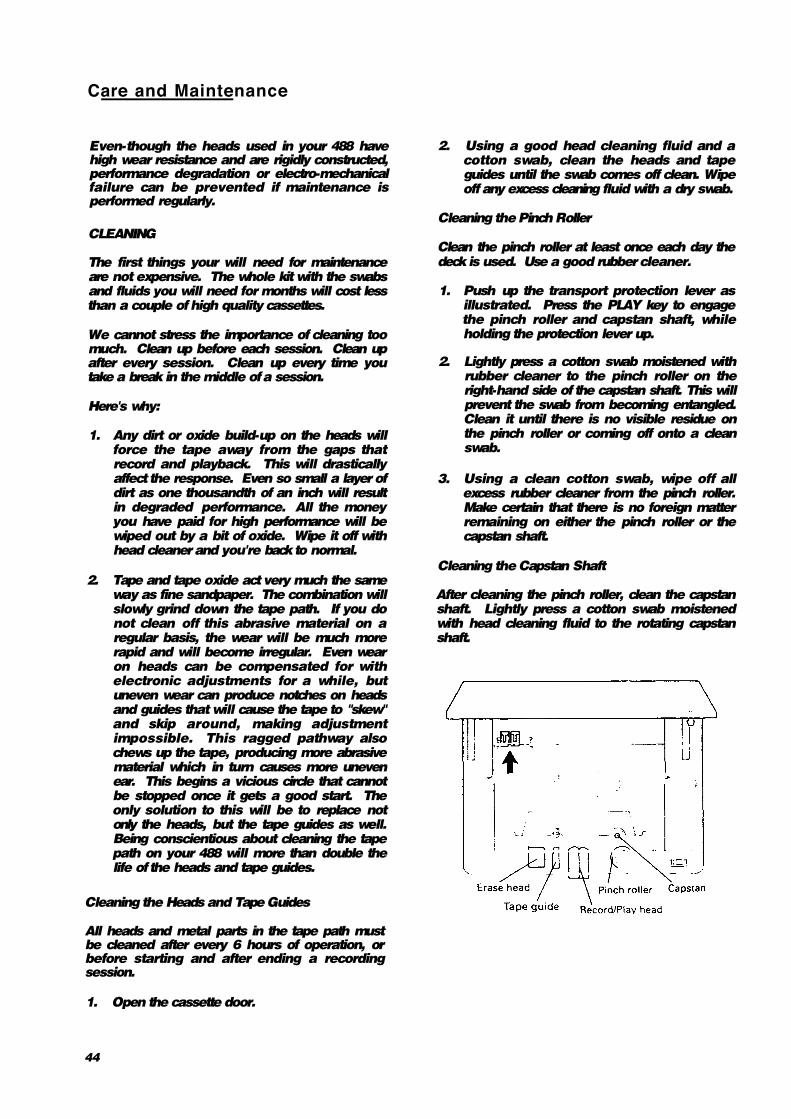
1. Open the cassette door.
2. Using a good head cleaning fluid and a cotton swab, clean the heads and tape guides until the swab comes off clean. Wipe off any excess cleaning fluid with a dry swab.
Cleaning the Pinch Roller
Clean the pinch roller at least once each day the deck is used. Use a good rubber cleaner.
1. Push up the transport protection lever as illustrated. Press the PLAY key to engage the pinch roller and capstan shaft, while holding the protection lever up.
2. Lightly press a cotton swab moistened with rubber cleaner to the pinch roller on the right-hand side of the capstan shaft. This will prevent the swab from becoming entangled. Clean it until there is no visible residue on the pinch roller or coming off onto a clean swab.
3. Using a clean cotton swab, wipe off all excess rubber cleaner from the pinch roller. Make certain that there is no foreign matter remaining on either the pinch roller or the capstan shaft.
Cleaning the Capstan Shaft
After cleaning the pinch roller, clean the capstan shaft. Lightly press a cotton swab moistened with head cleaning fluid to the rotating capstan shaft.
44

How the dbx Works
DEGAUSSING (DEMAGNETIZING)
A little stray magnetism can become quite a big nuisance in tape recording. It only takes a small amount (.2 Gauss) to cause trouble on the record head. Playing 10 cassettes will put about that much charge on the heads. A little more than that (.7 Gauss) will start to erase high frequency signals on previously recorded tapes. You can see that it's worth taking the trouble to degauss regularly.
DEGAUSSING IS ALWAYS DONE WITH THE RECORDER TURNED OFF. If you try it with the electronics on, the current pulses produced by the degausser will look just like audio signals to the heads. These pulses are around 10,000 Gauss, and will seriously damage the electronics and/ or meters. Turn off your 488, then turn on the degausser at least 1 m (3 feet) away from the recorder.
Be certain that your degausser has either a plastic cover or plastic tape covering the tip. Make sure that no metal ever touches the tape heads as it will scar them and ruin them.
Slowly move in to the tape path. Move the degausser slowly back and forth, touching lightly all metal parts in the tape path. Slowly move it away again to at least 1 m (3 feet) from the recorder before turning if off.
Be sure to concentrate while you are degaussing. Don't try to hold a conversation or think of anything else but the job you are doing. If the degausser is turned on or off by accident while it is near the heads, you may put a permanent magnetic charge on them that no amount of careful degaussing will remove. You will have to get the heads replaced. Make sure you are wide awake for this job.
A clean and properly demagnetized tape recorder will maintain its performance without any other attention for quite a while. It won't ruin previously recorded material, nor will getting it back to original specifications be difficult.
CAUTION: If the surface of the unit gets dirty, wipe the surface with a soft cloth or use a diluted neutral cleaning fluid. Clean off thoroughly. Do not use thinner, benzine, or alcohol, as they may damage the surface of the unit.
The DBX is a wide-band compression-expansion system which provides a net noise reduction (broadband, not just hiss) of a little more than 30 dB. In addition, the compression during recording permits a net gain in tape headroom of about 10 dB.
A compression factor of 2:1 is used before recording; then, 1:2 expansion on reproduce. These compression and expansion factors are linear in decibels and allow the system to produce tape recordings with over a 90 dB dynamic range - an important feature, especially when you're making live recordings. The DBX employs RMS level sensors to eliminate compressor-expander tracking errors due to phase shifts in the tape recorder, and provides excellent transient tracking capabilities.
To achieve a large reduction in audible tape hiss, without danger of overload or high-frequency self-erasure on the tape, frequency pre-emphasis and de-emphasis are added to the signal and RMS level sensors.
SUBSONICS AND INTERFERENCE
The DBX incorporates an effective bandpass filter. This filter suppresses undesirable subsonic frequencies to keep them from introducing errors into the encode or decode process. However, if rumble from trains or trucks is picked up by your microphone and fed to the DBX, modulation of the program material during low level passages may occur. This low-frequency component will not itself be passed through the recorder and so, will not be present at reproduce for proper decoding. It this low-level decoding error is encountered, and subsonics are suspected, we suggest the addition of a suitable high-pass filter in the Microphone Line.
45

Troubleshooting
Problem Possible Cause
Playback sound poor in brightness Dirty heads
Playback level won't rise Dirty heads
No playback sound TAPE controls set to OFF
Transport keys not effective Power turned off, or tape not loaded
No tape motion PAUSE pressed
No recording Cassette tab broken, or RHSL engaged
Wrong tracks recorded PAN/ASSIGN improperly set
Erratic playback pitch PITCH CONTROL set to a different position than during recording
Problem: Old tracks are always recorded along with new material.
Solution: Use the CUE section instead of the main mixer for monitoring previous tracks.
Problem: Recording are noisy.
Solution: Make sure all mixer channel ASSIGN switches are off except ones you are using. Also,
increase the volume faders of the instruments themselves — the 488 channel and master faders
should not have to be "full up" at any time.
Problem: Erratic tape sync.
Solution: Try to re-record the track through the 488 mixer; connect your sync tone generator to a
channel of the mixer, route that to Group 4, and press RECORD FUNCTION 8. This allows you to
use the mixer controls to adjust the track's recording level. The proper level should be between
-10 and 0 dB on the TRK 8 meter. Be sure to set both the SYNC and DBX NR switches to OFF.
Specifications
Mechanical Characteristics
Tape: Track Format: Head Configuration:
Motor:
Tape Speed: Pitch Control: Wow and Flutter: Fast Winding Time: Dimension (WxHxD): Weight:
Compact Cassette (C-30 to 90), High-Bias (Type II, CrO2) 8-track/8-channel, single directional record/play 8-channel record/play (sendust) x 1 8-channel erase (ferrite) x 1 DC servo capstan motor x 1 DC reel motor x 1 DC ancillary motor x 1 9.5 cm/sec.(3-3/4 ips), ± 1% ± 12 % (approx.) 0.04% WRMS, ± 0.06 % W.Peak 80 sec. (approx.) with C-60 490 x 125 x 392 mm (19-5/16" x 4-15/16" x 15-7/16") 7 kg (15-7/16 lbs.)
46

Electrical Characteristics
Mixer Section
MIC/LINE input (1/4" phone jack x 2) Input Impedance: Nominal Input Level: Maximum Input Level:
LINE input (1/4" phone jack x 6) Input Impedance: Nominal Input Level: Maximum Input Level:
50k ohms -50 dBV (3mV) at Trim Max. ~ -10 dBV (0.3 V) at Trim Min. +8 dBV (2.5 V) at Trim Min.
20k ohms -10 dBV (0.3 V) +8 dBV (2.5 V)
STEREO INPUTS (1/4" stereo phone jack x 2) Input Impedance: Nominal Input Level: Maximum Input Level:
GROUP OUT (RCA jack x 4) Output Impedance: Nominal Load Impedance: Minimum Load Impedance: Nominal Output Level:
EFFECT SENDS (1/4" phone jack x 2) Output impedance: Nominal Load Impedance: Minimum Load Impedance: Nominal Output Level:
PHONES (1/4" stereo phone jack x 1) Nominal Load Impedance: Maximum Output Level:
EQUALIZER HIGH (Shelving): LOW (Shelving):
Recorder Section
Record/Playback Channel: Noise Reduction:
SYNC IN (RCA jack x 1) Input Impedance: Nominal Input Level:
SYNC OUT (RCA jack x 1) Output Impedance: Nominal Load Impedance: Minimum Load Impedance: Nominal Output Level:
20k ohms -10 dBV (0.3 V) +8 dBV (2.5 V)
100 ohms 10k ohms 2k ohms -10 dBV (0.3 V)
100 ohms 10k ohms 2k ohms -10 dBV (0.3 V)
8 ohms 100 mW + 100 mW (at 8 ohms)
10 kHz, ±12 dB 100 Hz, ±12 dB
8 in number (4 channel simultaneous) dbx* NR (with a IN/OUT switch; ch. 8 disconnected from NR as long as the SYNC switch is ON)
10k ohms -10 dBV (0.3 V)
100 ohms 10k ohms 2k ohms -10 dBV (0.3 V)
Others
Power Requirements USA/CANADA: U.K./AUSTRALIA: EUROPE:
Power Consumption:
120 VAC, 60 Hz 240 V AC, 50 Hz 220 V AC, 50 Hz 30 W
47
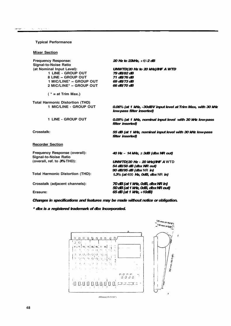
Typical Performance
Mixer Section
Frequency Response: Signal-to-Noise Ratio (at Nominal Input Level):
1 LINE - GROUP OUT 8 LINE ~ GROUP OUT 1 MIC/LINE* ~ GROUP OUT 2 MIC/LINE* ~ GROUP OUT
( * = at Trim Max.)
Total Harmonic Distortion (THD) 1 MIC/LINE - GROUP OUT
1 LINE - GROUP OUT
Crosstalk:
Recorder Section
Frequency Response (overall): Signal-to-Noise Ratio (overall, ref. to 3% THD):
20 Hz to 22kHz, +1/-2 dB
UNWTD(20 Hz to 20 kHz)/IHF A WTD
79 dB/82 dB
71 dB/76 dB
69 dB/73 dB
66 dB/70 dB
0.06% (at 1 kHz, -30dBV input level at Trim Max, with 30 kHz
low-pass filter inserted)
0.05% (at 1 kHz, nominal input level with 30 kHz low-pass
filter inserted)
55 dB (at 1 kHz, nominal input level with 30 kHz low-pass
filter inserted)
40 Hz ~ 14 kHz, ± 3dB (dbx NR out)
UNWTD(20 Hz - 20 kHz)/IHF A WTD 54 dB/58 dB (dbx NR out)
90 dB/95 dB (dbx NR in)
1.3% (at 400 Hz, 0dB, dbx NR in) Total Harmonic Distortion (THD):
Crosstalk (adjacent channels):
Erasure:
Changes in specifications and features may be made without notice or obligation.
* dbx is a registered trademark of dbx Incorporated.
70 dB (at 1 kHz, 0dB, dbx NR in) 50 dB (at 1 kHz, 0dB, dbx NR out) 65 dB (at 1 kHz, +10dB)
490mm(19-5/16")
48

Level Diagrams
MIXER SECTION
49

RECORDER SECTION
50

Optional Accessories
RC-30P Remote Footswitch MTS-30 MIDI-Tape Synchronizer
Head Demagnetizer PW-2Y/PW-4Y Insertion Cable
TZ-261 Cleaning Kit (Except U.S.) HC-1 Head Cleaner & RC-1 Rubber Cleaner (U.S.only)
51
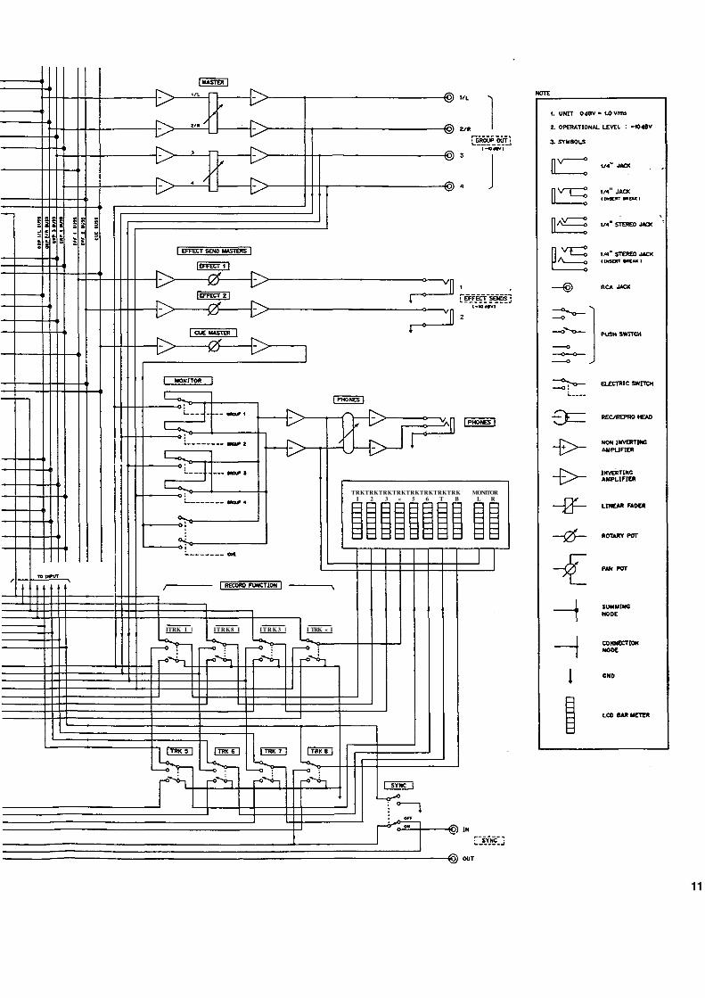
TRKTRKTRKTRKTRKTRKTRKTRK MONITOR I 2 3 « 5 6 T B L R
ITRK I | ITRK8 I I T R K 3 | I TRK « I
11

Block Diagram
I
S TRACK SOUNNEL REC/REPSO AMPLIFIER
0«X MR (ENCODER)

TASCAM TEAC Professional Division
488