task 1 deliverable report for: new technology research … · task 1 deliverable report . for: new...
TRANSCRIPT
Demonstration of a Verification-ready, Retrofittable Dual-loop EGR System for NOx Reduction without Aftertreatment
Task 1 Deliverable Report
for:
New Technology Research and Development Program
582-11-13469-2019
Submitted by:
QuantLogic Corporation
In collaboration with: Houston Advanced Research Center
Principal Investigators:
Deyang Hou, Ph.D., Yiqun Huang, Ph.D.,
& John Colvin
October 10, 2011
The preparation of this report is based on work funded in part
by the State of Texas
through a Grant from the Texas Commission on Environmental Quality
i
Table of Contents
ABSTRACT/EXECUTIVE SUMMARY .................................................................................................................. 4
INTRODUCTION / BACKGROUND ....................................................................................................................... 5
PROJECT OBJECTIVES / TECHNICAL APPROACH........................................................................................ 5
TASKS .......................................................................................................................................................................... 5
TASK 1 PROCURE COMPONENTS ................................................................................................................................ 6 Specification of Rapid prototyping engine control unit (ECU) ............................................................................. 6 Dual Loop EGR Configuration ........................................................................................................................... 10
DISCUSSION/OBSERVATIONS ............................................................................................................................ 13
OBJECTIVES VS. RESULTS ........................................................................................................................................ 13
SUMMARY/CONCLUSIONS .................................................................................................................................. 14
ACKNOWLEDGEMENTS ...................................................................................................................................... 14
ii
Table of Figures
Figure 1: G2.9 HUEI injector used in the International DT570 test engine ................................................. 7
Figure 2: HUEI injector driver output illustration ....................................................................................... 8
Figure 3: OpenECU (Pi-Shurlok) signal and actuator driver configuration ................................................. 9
Figure 4: Rapid prototyping engine control system (OpenECU) and wireharness ....................................... 9
Figure 5: Crank angle encoder from Kistler for low emission combustion analysis .................................. 10
Figure 6: Low pressure loop EGR configuration ........................................................................................ 11
Figure 7: Installation of sensors for pressure and temperature measurement for low pressure loop EGR control ......................................................................................................................................................... 11
Figure 8: Illustration of major dual loop EGR components as installed ..................................................... 12
Figure 9: Engine setup and components installed ....................................................................................... 13
iii
Abstract/Executive Summary
This project will develop a technology much needed for reducing nitrogen oxide (NOx) and particulate matter (PM) emissions from heavy-duty trucks, especially drayage trucks used in Texas ports and rail terminals. Drayage trucks are significant emissions sources for ports and rail terminals around the nation. However, the current United States Environmental Protection Agency (EPA) or California Air Resources Board (CARB) verified technologies for NOx reduction are mostly urea selective catalytic reduction (SCR) based. The urea-SCR technologies, no matter under retrofit or first fit, are not effective for drayage cycles because they are unable to maintain SCR light-off temperature. Exhaust gas recirculation (EGR) is the most effective way to reduce engine-out NOx emissions through reducing engine combustion temperature which contributes to lower NOx emissions.
Traditional high pressure loop EGR method tends to increase smoke emissions especially at high engine loads. Alternative combustion modes with high EGR rates from an advanced EGR system have shown to be being more effective in NOx reduction.
The effectiveness of advanced Dual Loop EGR system for retrofit drayage truck application has been demonstrated by the investigators in a previous New Technology Research and Development (NTRD) grant project with 50% NOx reduction over light to medium loads under steady-state conditions without any fuel penalty.
The benefits of this proposed project include a fully developed dual loop EGR system and demonstration over the full engine speed and load range including transient conditions with a 50% NOx reduction goal over light to medium loads for drayage truck applications. The complete dual loop EGR system will be implemented on the target vehicle for mileage accumulation and durability demonstration for future verification purpose.
4
Introduction / Background
Drayage trucks are significant emission sources for Texas ports. However, urea-SCR retrofit technologies are not effective for drayage cycles because they are unable to maintain SCR light-off temperature. Exhaust gas recirculation (EGR) is the most effective way to reduce engine-out NOx emissions through reducing engine combustion temperature which attributes to high NOx emissions. Traditional high pressure loop EGR method tends to increase smoke emissions especially at high engine loads. Alternative combustion modes with high EGR rates from an advanced EGR system have shown to be being more effective in NOx reduction.
The effectiveness of advanced Dual Loop EGR system for retrofit drayage truck application has been demonstrated by the applicant in a previous NTRD project with 50% NOx reduction over light to medium loads under steady-state conditions without any fuel penalty.
In the new project, the dual loop EGR system will be fully developed and demonstrated over the full engine speed and load range including transient conditions with a 50% NOx reduction goal over light to medium loads for drayage truck applications. The complete dual loop EGR system will be implemented on the target vehicle for mileage accumulation and durability demonstration for future verification purpose.
Project Objectives / Technical Approach
The objectives for this work are to: develop a drayage truck retrofit dual-loop EGR system resulting in at least 50% NOx reduction under light to medium load without after-treatment, and demonstrate the prototype retrofit on a drayage truck to begin accumulating hours in preparation for verification testing.
Tasks
The following seven tasks are identified in the Grant Activities (Scope of Work):
Task 1: Procure Components,
Task 2: Set up engine retrofit and engine control systems,
Task 3: Steady-state engine calibration and emissions testing,
Task 4: Transient control strategy development and testing,
Task 5: Transient emissions tuning and testing,
Task 6: Vehicle installation of retrofit,
Task 7: Reporting.
The Task 1 accomplishment and hardware specifications are summarized below.
5
Task 1: Procure Components
From the Grant Activites (Scope of Work):
Task 1: Procure Components
2.1. Task Statement: The PERFORMING PARTY will finalize the specifications for and procure all test components needed for the completion of the project.
2.1.1. The PERFORMING PARTY will finalize the specifications for components and the dual loop EGR configuration based on the target engine, an International 9.3L 2004 to 2007 model year HT570 or DT570 heavy duty diesel engine, and vehicle configuration and dimensions.
2.1.2.. The PERFORMING PARTY will procure all test components needed for the completion of the project, including: target test engine, low and high pressure loop EGR valves and coolers, throttle valves, prototyping engine control system, temperature, pressure and air flow sensors, NOx and O2 sensors, DOC, DPF, cylinder pressure sensors, etc.
2.1.3. Schedule: The PERFORMING PARTY shall complete this task within 3 months of the signed Notice to Proceed Date as issued by TCEQ.
2.1.4. Deliverables: The PERFORMING PARTY shall submit a report to the TCEQ upon completion of this task. This report will include but is not limited to the final component and dual loop EGR configuration specifications.
All components for the current engine setup and dual loop EGR systems have been procured. The remaining 10% of the procurement is related to the final optimized vehicle retrofits and will require more precise configuration such as dimensions for retrofit and results from the combustion and emission testing. It is more efficient to accomplish them at the stage after the emission reductions development and before the vehicle retrofit stage. The major procured components for the dual loop EGR, combustion and emissions development include:
Driveshaft and flywheel adaptor for connecting dyno to the engine flywheel;
Rapid prototyping engine control system (open engine control unit) and wire harness;
Crankshaft encoder, sensors (temperature, pressure, and NOx/O2), and actuators;
Exhaust aftertreatment devices (DOC and DPF);
EGR cooler for low pressure loop EGR; and
Exhaust plumbing for high and low pressure loop EGR.
The remaining 10% of the procurement work will be associated with all remaining tasks up to Task 6, thus it will be reported along with report of Task 6.
6
Specification of Rapid prototyping engine control unit (ECU)
ECU is a key component to the implementation of low engine-out emissions control strategy. An open-ECU platform is a best fit for the project for its flexibility of programming and robustness for vehicle installation and application at the vehicle retrofit stage of the project.
Four different types of open ECU (rapid prototyping control system) were investigated for functions of sensor inputs, actuator drive outputs, injector driver capability, etc. They are:
RapidPro+MicroAutoBox from dSPACE Inc,
MotoHawk from Woodward,
Compact Rio from National Instrument, and
M250+S070 OpenECU from Pi-Shurlok.
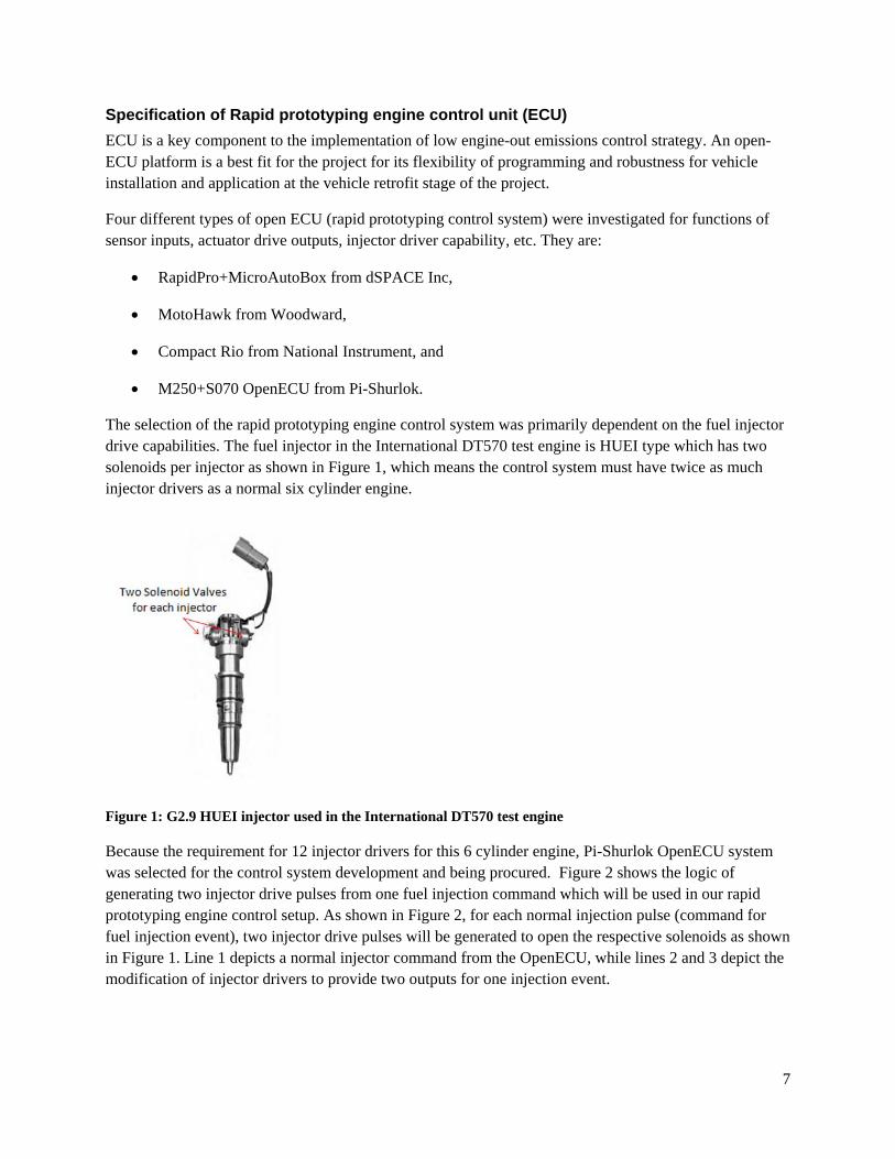
The selection of the rapid prototyping engine control system was primarily dependent on the fuel injector drive capabilities. The fuel injector in the International DT570 test engine is HUEI type which has two solenoids per injector as shown in Figure 1, which means the control system must have twice as much injector drivers as a normal six cylinder engine.
Figure 1: G2.9 HUEI injector used in the International DT570 test engine
Because the requirement for 12 injector drivers for this 6 cylinder engine, Pi-Shurlok OpenECU system was selected for the control system development and being procured. Figure 2 shows the logic of generating two injector drive pulses from one fuel injection command which will be used in our rapid prototyping engine control setup. As shown in Figure 2, for each normal injection pulse (command for fuel injection event), two injector drive pulses will be generated to open the respective solenoids as shown in Figure 1. Line 1 depicts a normal injector command from the OpenECU, while lines 2 and 3 depict the modification of injector drivers to provide two outputs for one injection event.
7

Figure 2: HUEI injector driver output illustration
In the later vehicle retrofitting phase, a production oriented ECU will be procured.
The configuration of OpenECU, injector drivers as well as input signals is shown in Figure 3. Two M250 OpenECU will be linked as “Master and Slave” configuration via CAN2.0 communication line. Each of the M250 will control a S070 injector drive to control 3 injectors (6 solenoids). The signals from various sensors and drive of other actuators such as EGR valves and Variable Geometry Turbocharger (VGT) can either be connected to the master controller alone or can be parallel to each controller at the same time. Figure 3 shows the signal and actuator drive configuration with the OpenECU system.
8
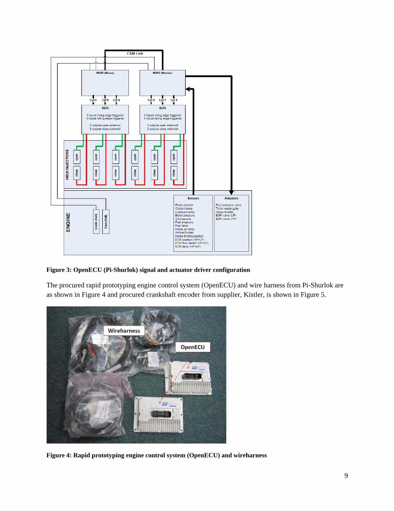
Figure 3: OpenECU (Pi-Shurlok) signal and actuator driver configuration
The procured rapid prototyping engine control system (OpenECU) and wire harness from Pi-Shurlok are as shown in Figure 4 and procured crankshaft encoder from supplier, Kistler, is shown in Figure 5.
Figure 4: Rapid prototyping engine control system (OpenECU) and wireharness
9
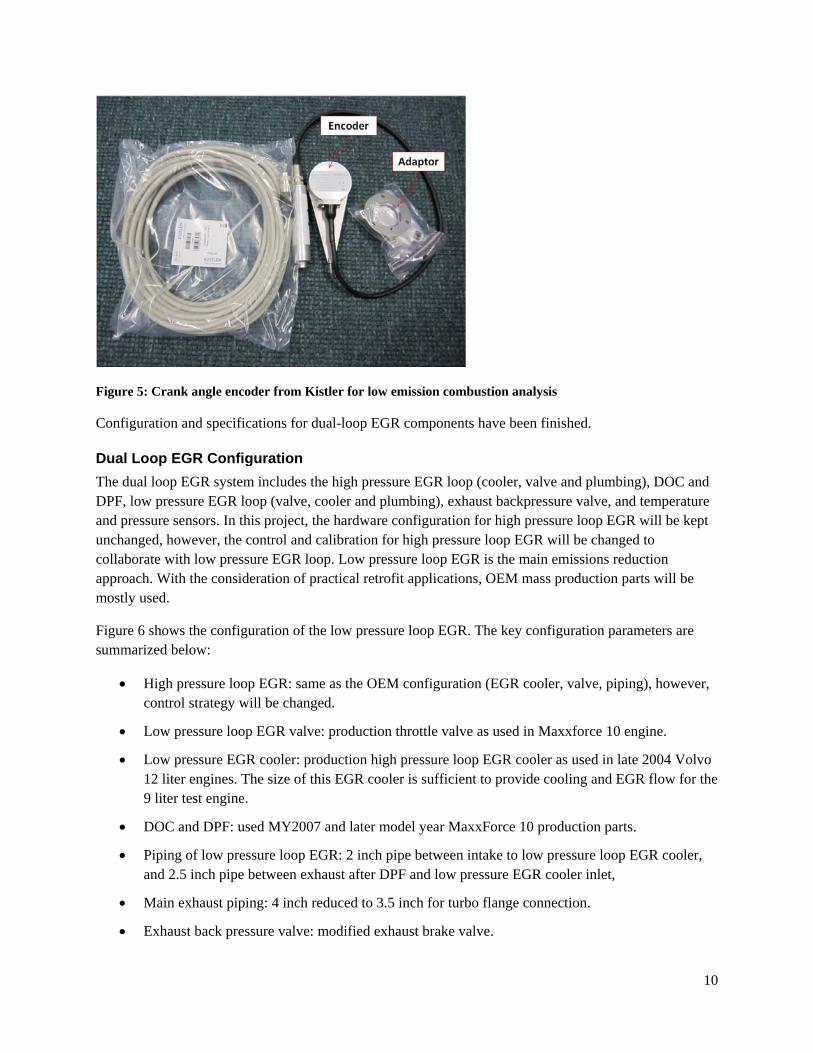
Figure 5: Crank angle encoder from Kistler for low emission combustion analysis
Configuration and specifications for dual-loop EGR components have been finished.
Dual Loop EGR Configuration
The dual loop EGR system includes the high pressure EGR loop (cooler, valve and plumbing), DOC and DPF, low pressure EGR loop (valve, cooler and plumbing), exhaust backpressure valve, and temperature and pressure sensors. In this project, the hardware configuration for high pressure loop EGR will be kept unchanged, however, the control and calibration for high pressure loop EGR will be changed to collaborate with low pressure EGR loop. Low pressure loop EGR is the main emissions reduction approach. With the consideration of practical retrofit applications, OEM mass production parts will be mostly used.
Figure 6 shows the configuration of the low pressure loop EGR. The key configuration parameters are summarized below:
High pressure loop EGR: same as the OEM configuration (EGR cooler, valve, piping), however, control strategy will be changed.
Low pressure loop EGR valve: production throttle valve as used in Maxxforce 10 engine.
Low pressure EGR cooler: production high pressure loop EGR cooler as used in late 2004 Volvo 12 liter engines. The size of this EGR cooler is sufficient to provide cooling and EGR flow for the 9 liter test engine.
DOC and DPF: used MY2007 and later model year MaxxForce 10 production parts.
Piping of low pressure loop EGR: 2 inch pipe between intake to low pressure loop EGR cooler, and 2.5 inch pipe between exhaust after DPF and low pressure EGR cooler inlet,
Main exhaust piping: 4 inch reduced to 3.5 inch for turbo flange connection.
Exhaust back pressure valve: modified exhaust brake valve.
10
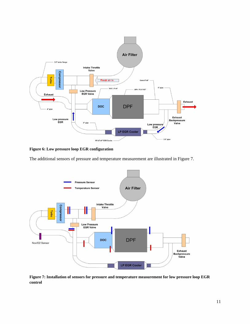
Figure 6: Low pressure loop EGR configuration
The additional sensors of pressure and temperature measurement are illustrated in Figure 7.
Figure 7: Installation of sensors for pressure and temperature measurement for low pressure loop EGR control
11
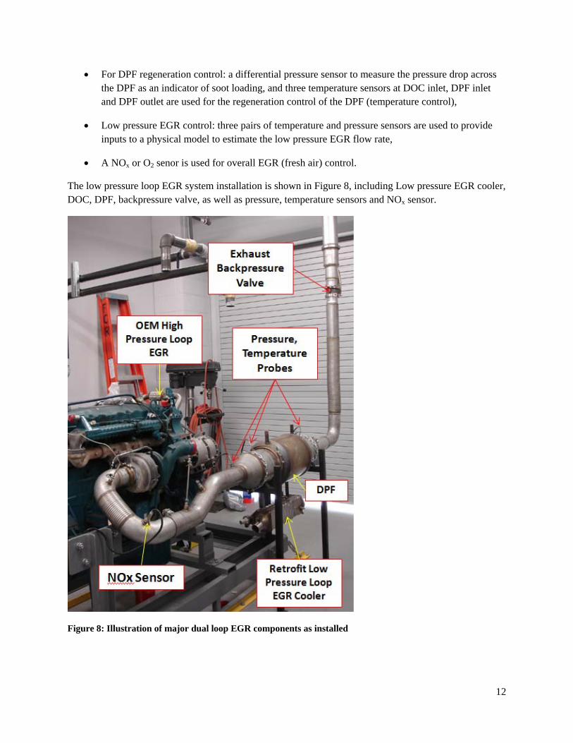
For DPF regeneration control: a differential pressure sensor to measure the pressure drop across the DPF as an indicator of soot loading, and three temperature sensors at DOC inlet, DPF inlet and DPF outlet are used for the regeneration control of the DPF (temperature control),
Low pressure EGR control: three pairs of temperature and pressure sensors are used to provide inputs to a physical model to estimate the low pressure EGR flow rate,
A NOx or O2 senor is used for overall EGR (fresh air) control.
The low pressure loop EGR system installation is shown in Figure 8, including Low pressure EGR cooler, DOC, DPF, backpressure valve, as well as pressure, temperature sensors and NOx sensor.
Figure 8: Illustration of major dual loop EGR components as installed
12
Discussion/Observations
Objectives vs. Results
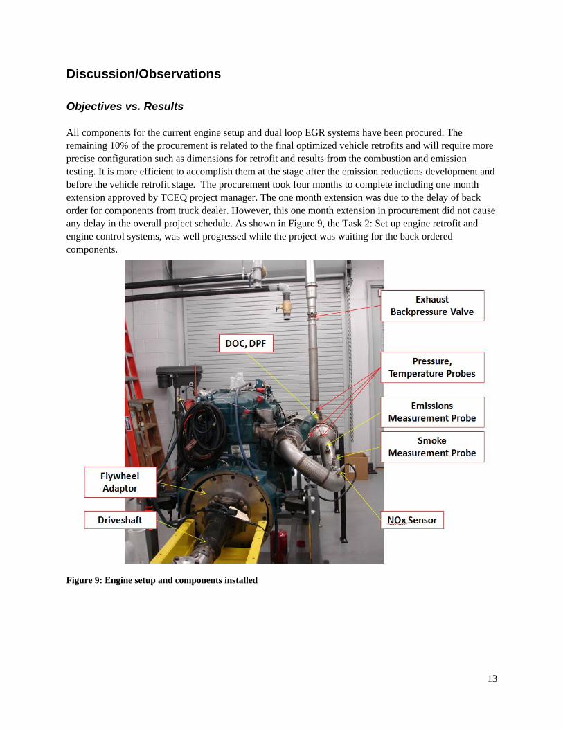
All components for the current engine setup and dual loop EGR systems have been procured. The remaining 10% of the procurement is related to the final optimized vehicle retrofits and will require more precise configuration such as dimensions for retrofit and results from the combustion and emission testing. It is more efficient to accomplish them at the stage after the emission reductions development and before the vehicle retrofit stage. The procurement took four months to complete including one month extension approved by TCEQ project manager. The one month extension was due to the delay of back order for components from truck dealer. However, this one month extension in procurement did not cause any delay in the overall project schedule. As shown in Figure 9, the Task 2: Set up engine retrofit and engine control systems, was well progressed while the project was waiting for the back ordered components.
Figure 9: Engine setup and components installed
13
Summary/Conclusions
The goals of the Task 1 were accomplished. The specifications of components and the dual loop EGR configuration based on the target engine and vehicle configuration and dimensions were determined, and all components for the current engine setup and dual loop EGR systems have been procured. The remaining 10% of the procurement is related to the final optimized vehicle retrofits and will require more precise configuration such as dimensions for retrofit and results from the combustion and emission testing. It is more efficient to accomplish them at the stage after the emission reductions development and before the vehicle retrofit stage. The procurement task took four months to complete including one month extension approved by TCEQ project manager.
The project is currently under Task 2: Set up engine retrofit and engine control systems. The overall project progress is within the original planned schedule and budget.
Acknowledgements
The principal investigators are grateful for the support from TCEQ project management team, especially for the guidance and many helps from Ms. Katherine Williams. QuantLogic is also grateful for the diligent and excellent work conducted by the team of Houston Advanced Research Center, and the kind help from International Trucks of Houston for part procurements.
14