taverna, · pdf filetaverna, reloaded paolo missier 1, stian soiland-reyes , stuart owen , wei...
TRANSCRIPT

Taverna, reloaded
Paolo Missier1, Stian Soiland-Reyes1, Stuart Owen1, Wei Tan2, Alexandra Nenadic1, Ian Dunlop1,Alan Williams1, Tom Oinn3, and Carole Goble1
1 School of Computer Science, The University of Manchester, UK2 Mathematics and Computer Science Division, Argonne National Laboratory, Argonne., IL., USA
3 European Bioinformatics Institute, UK
Abstract. The Taverna workflow management system is an open source project with ahistory of widespread adoption within multiple experimental science communities, and a long-term ambition of effectively supporting the evolving need of those communities for complex,data-intensive, service-based experimental pipelines. This paper describes how the recentlyoverhauled technical architecture of Taverna addresses issues of efficiency, scalability, andextensibility, and presents performance results based on a collection of synthetic workflows,as well as a concrete case study involving a production workflow in the area of cancer research.
1 Introduction
Taverna [10] is a workflow language and computational model designed to support the automationof complex, service-based and data-intensive processes. Although Taverna has been successfullyapplied in domains as diverse as bioinformatics, astronomy, medical research, and music, it isperhaps best known for its application to the Life Sciences [6, 15], where it has been used to supportexperimental investigation into a variety of research areas, including gene and protein sequence andstructure annotation, proteomics, microarray analysis, text mining, systems biology, and more. Thefirst version, launched in 2004 [18], has enjoyed broad adoption over the years4, owing in part toa fairly intuitive model for service composition, and to a growing number (in the order of tensof thousands) of available services, mostly community-provided and free to use, and to Taverna’sability to invoke ad hoc scripts and Java object methods.
Taverna combines a dataflow model of computation [14], whereby a workflow consists of aset of processors (representing software components such as Web Services) that are connectedthrough data dependencies links, with a functional model that accounts for collection-orientedprocessing. This hybrid model is designed to strike a balance between expressivity and simplicity,with the ultimate goal of empowering users, who may have only a rudimentary understanding ofprogramming, to assemble complex workflows. While the model and its theoretical underpinnings[23] have remained largely stable over the years, the evolving requirements of e-science applicationshave recently prompted a radical re-design of the architecture, which we will refer to as “Taverna2” (T2 for short) to distinguish it from the previous version, T1.x.
This paper presents the salient features of the new architecture, which has two main goals.Firstly, to improve the scalability of workflow execution, both in terms of data volume and executiontimes, over its predecessor. Secondly, to provide third-party developers with clear configurationpoints for performance tuning, and with extensibility points for adding new high-level constructs,4 In 2008 there were over 4000 active users of Taverna, a year-on-year increase of 43%. Currently it stands
at more than 57,000 downloads total, running at 40 downloads/day.

such as a while-loop, to the dataflow model, in order to facilitate workflow design in paradigmaticscenarios. More specifically, the following architectural requirements have inspired the design of theT2 architecture:
Parallelism. Models of computation that combine dataflow and functional models are known tofacilitate parallel execution [13], making the exploitation of the parallelism provided implicitlyby the workflow specification a realistic goal. Potential parallelism can be found both amongstprocessors (inter-processor), by statically determining data dependencies amongst processors inthe dataflow graph, as well as amongst multiple invocations of the same processors (intra-processordata parallelism), i.e., on individual elements of an input collection.
Configurability. Each processor may have different operational requirements, for example regardingits tolerance to transient error conditions in the underlying service invocation. Thus, it should bepossible to fine-tune the behaviour of each processor independently from that of the others.
Openness. It should be possible for third party contributors to extend the functionality of theexecution model in a principled way. For example, interacting with asynchronous services thatrequire periodic polling to check on result availability, does not fit the data-driven model well.While in T1.x the model can be “stretched” to simulate polling processors, T2 accommodatesthis requirement by implementing a limited form of while-loop construct by exploiting a genericextensibility mechanism, called the dispatch stack.
Separation of data and process spaces. For data-centric computing to scale to arbitrary data vol-umes, the data space should be managed separately from the process space, and, whenever possible,data should be passed from one processor to the next by reference rather than by value.
This paper describes how the design principles listed above have been translated into a coherentarchitectural design for T2, and presents performance results for the current implementation.
1.1 Related work
Workflow modelling for data-intensive scientific applications is, of course, not new. One of therecognized challenges of scientific workflow management systems is to provide abstract modellingconstructs that are then automatically instantiated as an orchestration of concrete tasks that ex-ecute on an sunderlying parallel architecture [4, 9]. This is the approach taken for example by thePegasus system [5] and exemplified in the CyberShake case study [3], with the goal of decouplingthe logical specification of the workflow from the pool of resources required to execute it. In thisparadigm, resources are allocated by the scheduler incrementally and dynamically. In a similarfashion, Chimera [7] provides a dedicated language (VDL) for the partial specification of logicalworkflows. A complementary, bottom up approach, is to start with a job management system, likeCondotr, and then provide users with a model for building complex workflows from a pool of indi-vidual jobs [1]. Another example of concrete and well-known mechanism used for the specificationof complex dataflows is shell pipes, proposed in [26]. Finally, an interesting development [27] ofthe Kepler workflow manager is its integration with Hadoop5, an open-source implementation of
5 http://hadoop.apache.org/.

the MapReduce pattern [2]. Thanks to this integration, Kepler users are able to specify MapRe-duce problems at a high level, leaving the details of its realization through the Hadoop API to theworkflow manager.
While the Taverna workflow manager shares some of the goals of abstraction and dataflow-basedparallelism, the majority of the workflows designed by its traditional user base, for the most partin the bioinformatics domain, are rather more data-intensive than compute-intensive. Typically,Taverna workflows perform some form of “on-the-fly data integraton” on large collections of datavalues retrieved from a variety of databases through their Web service interfaces, exposed as Tavernaprocessors. In this setting, each of the available parallel threads tends to carry a potentially largedata item, while involving very small amount of computation. Also, its execution is bound to thatof some underlying remote service, making an explicit mapping of Taverna threads to a parallelarchitecture less of a priority. Naturally, therefore, the emphasis in T2 has been on efficient datamanagement, by separating the data space from the process space as much as possible, and ondeveloper-facing features such as well-defined extensibility points. In turn, these translate into asimplification of the workflow design and testing phase, as well as access to large collection of thirdparty services in specific application domains.
1.2 Paper organization
The rest of the paper is organised as follows. The execution model is presented in Sec. 3; thedispatch stack model used for processor execution control is described in Sec. 3.1, its application tothe design of the while-loop operator is described in Sec. 5, and the separation of data and processspaces is discussed in Sec. 4. Performance results are presented in Sec. 6, followed by the descriptionof a concrete case study from the caGrid project, in Sec. 7.
2 Workflow model
We begin by briefly summarizing the Taverna computational model. While a full account is beyondthe scope of this paper, the formal semantics for T1.x and T2 has been independently described in[23] and [21], respectively6.
2.1 Dataflow specification
A Taverna workflow is specified by a directed graph where nodes, called processors, representsoftware components, typically Web Services or local scripts. A processor node consumes data thatarrives on its input ports and produces data on its output ports. Each arc in the graph connects apair of ports, and denotes a data dependency from the output port of the source processor to theinput port of the sink processor. Additionally, control links can be placed between a source and asink processor, to denote that the latter can only be executed after the former has produced all itsoutput.
An example of a Taverna workflow for bioinformatics appears in Fig. 1 (the workflow is publishedon the myExperiment website7). The workflow accepts one or more input collections of gene IDs,and for each such list, on output port paths per gene it produces a list of metabolic pathway IDs,6 The two papers follow different approaches to formally define essentially the same semantics.7 http://www.myexperiment.org/workflows/778

obtained from the KEGG pathway database8, which involve each of the genes in the list. In thismodel, data items are either of a simple type (string, number, etc.), or are lists of items, nestedto arbitrary levels. For example, list [[mmu:26416, mmu:34212 ],[mmu:328788]] is a valid input forthe example workflow.
Conceptually, a workflow computation proceeds by pushing data through the directed datalinks from one processor to all of its successors, starting with the items that are presented on theworkflow inputs. A processor is ready to execute when all of its inputs ports are populated with adata item. A processor’s execution consists of the invocation of an associated activity, for examplea Web Service or a local script, and produces new data items on its output ports. These are thenpropagated along the outgoing arcs.
Importantly, an activity can itself be a workflow, i.e., an entire workflow can be associatedto any individual processor. This makes the Taverna model closed under activity composition,i.e., a workflow is a composition of activities, and can be an activity itself. This dual nature ofworkflows results in a structurally recursive model where a collection of elementary activities formsthe baseline layer. This has two main benefits: firstly, it can be used to support control constructsfrom traditional programming languages, such as a while-loop, which operate on a “body of code”;here the body is encapsulated within a sub-workflow. And secondly, it allows for the dynamicspecification of workflows, by allowing the late binding of activities to processors, a feature thatwas found to be useful in certain contexts [8], and which opens the way for service discovery tooccur at workflow execution time.
Fig. 1. Taverna workflow for metabolic pathways lookup
8 http://www.genome.jp/kegg/pathway.html

2.2 List data types
The handling of input lists by processors in Taverna is based upon the declared depth associated toeach input port. The depth denotes the level of nesting of the expected input, where an atomic inputhas depth = 0. For example, the list [ [’red’, ’blue’], [’fox’, ’parrot’]] has depth 2. For processorsthat represent Web service operation invocations, the declared depth is determined automatically.Consider for example a KEGG Web service whose WSDL interface specification includes operationgetPathwayDescriptions, with a single input parameter string9, which accepts a string. Whenthe operation invocation is added to the workflow of Fig. 1, typically using the Taverna workbench(the visual environment used for workflow composition), a processor with the same name as theoperation, and one port of depth 0, are automatically generated.
During execution, the actual value that arrives on the port may have a different nesting levelthan expected. If the preceding processor get pathway by genes produces a simple list (of depth1) of pathway IDs, for example, there is a mismatch between the declared and the offered list depthon the port. In this case, list processing in Taverna is reminiscent of a functional computationalmodel: the mismatch of 1 between declared and offered depths causes the engine to iterativelyinvoke the processor over each element of the list. In each such invocation, the port is bound toan atomic value, as expected by the underlying service invocation. The results of each invocationare then collected into a new output list. In our example, since each invocation generates a list ofdescriptions for an input pathway ID, the final value on the return port is a list of lists, of depth2.
Iterations over collections have been formally described in terms of higher-order functions [13],and a complete account of the Taverna implicit iteration model can be found in [21]10. The implicitlist iteration semantics provides intra-processor parallelism, because the list elements that are beingiterated upon are independent from each other, and thus multiple processor instances that operateon those elements one at a time can potentially proceed in parallel (assuming they generate no sideeffects). Furthermore, implicit iterations may propagate through a sequence of iterating processors.For example, if getPathwayDescriptions, which expects a string, is presented with a list producedby the preceding processor, the computation again unfolds into multiple processor instances.
As we explain in the next section, the runtime architecture of Taverna is designed to exploitboth intra-processor parallelism, as well as the inter-processor parallelism that is implicit in thedataflow processing model.
3 Workflow processing model and architecture
We now describe the suite of architectural solutions adopted to realize each of the principles enun-ciated in the introduction. The overview architectural diagram is shown in Fig. 2.
A workflow specification is compiled into a multi-threaded object model (implemented in Java),where processors are represented by objects, and data transfers from output to input ports of down-stream processor objects are realized using local method invocations between objects. One or moreactivities are associated to each processor. These activities may consist of entire sub-workflows,in addition to executable software components. While data-driven computation in T1.x relies ona centralized workflow enactment system, in T2 there is no need for a central controller: as each9 This is the name chosen by KEGG for this parameter.
10 The full model described in [21] accounts for multiple mismatches on more than one input port. Thislevel of detail does not add much to our architectural discussion and is omitted.

Fig. 2. Overview block diagram of Taverna 2 architecture
processor is mapped to an object, it independently starts its own execution, in a separate thread,as soon as all of its (connected) input ports are populated with a data item, and it autonomouslytransfers its output along the arcs upon completion. Although execution is decentralized, a facadepattern is used to provide external components, notably the monitor and result presentation com-ponents in Fig. 2, with a single point of contact (a different facade is used for each workflow run).The monitor listens to various events emitted by the processors, which are translated into visualinformation on the progress of execution.
3.1 The dispatch stack
A processor’s execution culminates with the invocation of one of its associated activities. In doingso, however, a number of additional functionalities are involved, which collectively define a con-figurable and extensible runtime behaviour. These functionalities provide configurable quality ofservice management, and are implemented as separate components which are organized accordingto the interceptor design pattern. We use the terms layers and stack to denote the components andthe pattern, respectively, as this resembles the behaviour of a protocol stack, as shown in Fig. 3(a).The following standard layers (in the order they are presented) are defined for each processor:
Parallelise: this ensures that, when iterations over lists are involved, independent concurrent threadsare created to process each list element;
Error Bounce: is responsible for immediately terminating an execution when any of the inputs arein an error state. This protects the underlying activities from being invoked on invalid input;
Failover: detects the failure of an activity associated to the processor, and is responsible for selectingan alternate activity, if available (recall that activities can be added and removed dynamically);

Default dispatch stack
Parallelise
Error bounce
Failover
Invoke
Retry
Re
qu
es
t
(a) (b)
Re
sp
on
se
Re
qu
es
t
Re
sp
on
se
Extended dispatch stack
Parallelise
Error bounce
Failover
Invoke
Retry
Loop/Branching
Fig. 3. Processor dispatch stack
Retry: provides tolerance to transient errors in the underlying activity, by repeatedly attemptingthe same invocation for a configurable number of times.
The stack is activated by a request message to the processor, consisting of the data on the inputports. The message is pushed down the stack, where each layer performs its function and, if needed,forwards a new version of the request to the next layer. At the bottom of the stack, the Invokelayer performs the actual invocation of an activity; in the case of a Web Service invocation, forinstance, this layer is a Web Service client that maps the incoming request to a SOAP message,and manages the interaction with the service. The result is mapped to a response message, whichfinds its way back up along the stack, where it is intercepted by each layer, possibly transformed,and forwarded. Ultimately, the processor invocation terminates and the response is forwarded todownstream processors along the data links.
3.2 Configurability and extensibility
In this architecture, a private instance of the dispatch stack is associated to each processor, makingit configurable independently of the others. Also, the interceptor pattern naturally allows new layersto be added to the standard stack shown in Fig. 3(a)11. Useful additional layers that are alreadyavailable as part of the current release include the while-loop layer, shown in Fig. 3(b) and describedin more detail in Sec. 5, as well a Provenance layer, designed to generate audit events from theprocessor’s execution as a basis for collecting workflow provenance [17].
Layers are typically added and configured as part of the workflow design activity, but users neednot be aware of the stack architecture. For example, the Taverna workbench has a new option thatallows users to qualify any processor as a “while loop processor”, and to specify the correspondingelements, i.e., the loop exit condition and the body of the loop. The body in particular can be anelementary activity, or an entire sub-workflow (which, as explained in Sec. 2, is itself an activity).The workbench then maps this specification to a local stack configuration where the activity asso-ciated to the processor is precisely the body of the loop, and where a while-loop layer is added andconfigured with an automatically generated script for testing the exit condition.
Configuration parameters for the standard layers could potentially be similarly exposed throughadvanced settings in the workbench12. These include the number of allowed retries in the Retry layer,
11 Layers are Java classes that implement a particular interface.12 Currently, however, these settings can only be modified through a Java workflow management API.

the time delay between retries (needed to avoid flooding a Web Service with requests), as well asthe maximum number of concurrent threads available for intra-processor parallelism, used by theParallelise layer. Configuring the list of activities associated to a processor is especially important,as these typically represent alternative deployments of functionally equivalent services, which theFailover layer will try in succession in response to failures in service invocations.
Note also that a processor’s behaviour is also affected by the relative position of the layers in thestack (the Invoke layer, however, is always at the bottom of the stack). By switching the positionsof the Retry and Failover layers, for example, one obtains a processor that goes through the listof alternate services, trying each of them only once, but then iterates over the entire list a presetnumber of times.
3.3 Adding support for specific service types
We mentioned earlier that Taverna processors can be automatically generated in response to theuser’s request to add a Web service invocation to a workflow, by analysing the WSDL interfacespecification for the service. In some cases, however, interacting with the service requires the clientto support an extended protocol beyond standard SOAP. The caGrid services [25], for example,support state preservation across invocations, through the Web Services Resource Framework13,and furthermore, their clients must provide security credentials prior to accessing the service. Inorder to seamlessly interface with such services, Taverna provides a plugin architecture wherebythird party service providers can extend the workflow manager’s functionality through a ServiceProvider Interface (SPI), in order to support services with specific requirements. The SPI generalisesTaverna’s standard service discovery and automated client generation method, by letting providersimplement specific service discovery methods, as well as client generation code that is dedicated tothe specific services.
A discovery method for services of a certain type, for example caGrid, enables workflow designersto find services of that type, from locations that are known to the provider, and to add them tothe local Taverna service registry. Once the services are visible, they can be added to workflows asnormal. This, however, triggers the generation of client code that is specific for the service type. Inthe case of caGrid, the generated code supports the exchange of security credentials required by theservice as part of its initial handshake. Additionally, the SPI implementor may provide a provider-specific configuration UI that integrates with Taverna’s visual workbench. For caGrid, such a UI isused to obtain the security access credential from users, either at design or at execution time. ThecaGrid Taverna plugin is described in [22].
The plugin functionality is a vital component of Taverna’s open architecture, providing a way toaccommodate third party contributions, for example the Biomoby and Rshell plugins, which weredeveloped by external contributors but are now shipped as part of the core Taverna distribution.
3.4 Parallelism and pipelining
Inter-processor parallelism, which is available for processors that have no data dependency amongstthem, is achieved by letting those processors begin execution in a new thread as soon as they receivetheir input data. Since a request is pushed down the stack only when data is present on all theinput ports, this criterion is sufficient to ensure that data-independent processors can always execute
13 http://www.globus.org/wsrf/.

in parallel. The stack execution model also ensures intra-processor parallelism, by exploiting theimplicit iteration on collections described in Sec. 2. To recall, when a list appears on a port wherea simple type is expected, each element of the list is processed independently from the others.This is a case of SPMD parallel processing [11], where the same function is applied concurrentlyto multiple data elements, and potentially results in multiple independent pipelines (see also the“Multiple instances with a priori runtime knowledge” pattern described in [24]), and is achieved inT2 by having the Parallelise layer allocate one thread to each element in the input collection, withan appropriate setting for the max number of threads. Since this layer is at the top of the stack, thishas the effect of activating the processor on multiple concurrent requests (which may succeed orfail independently of one another). The collection of all the corresponding responses is then collatedinto a new output list, which is forwarded to the next processor. Since the requests may be servedat different speeds, the elements of the response collection may be produced in arbitrary order. TheParallelise layer deals with this by simply waiting for the last element to arrive, before emittingthe entire output list, with its order preserved. Additionally, however, a chain of processors whichboth iterate on their inputs, say P1 and P2, provide an opportunity for pipelining, as follows. TheParallelise layer of P1 forwards each response element as soon as it arrives, without waiting for theothers and regardless of its position in the collection. In P2, each such element is again independentof the rest of the list, so the Parallelise layer of P2 can consume it immediately as part of a newthread. When extended to a chain of iterating processors, this strategy results in multiple, parallelpipelines, where both intra- and inter-processor parallelism is maximized. Clearly, any processorthat requires to see the entire input before starting its processing represents a serialization point inthe pipeline.
This form of superscalar and streaming pipelining [19] provides the basis for efficiently support-ing workflow processing over streams of data, i.e., sequences of discrete input elements of unboundedlength that are continuously produced by a source. Biomart14[20] is an example of a service thatsupplies its output in a streamed fashion.
4 The Data Manager
In T1.x, the data produced and consumed by services needs to be entirely loaded into the enactor’sprocess space for as long as there are processors that need it, with the risk that large lists, or a fewlarge data items (images, for example) would consume unbounded memory resources. In contrast,the T2 data architecture is based on the principle that data is only loaded into the executionprocess space on demand, when it is required by some processor’s input port, and it is swappedout to a separate persistent storage when it is no longer needed. Thus, while the same data may betransferred back and forth from storage multiple times, the total amount of main memory requiredby an execution is bounded. The max memory footprint is determined by the size of each data itemand the number of concurrent threads that require in-memory data at any given time. As shownin the use case presented in Sec. 7, the max number of active threads, a parameter that can beconfigured independently for each processor, can be used to control the total amount of memoryrequired.
The separation of the data from the workflow execution space is achieved by registering allvalues that are produced during a computation with a new Data Manager (DM). The DM’s mainfunction is to index the values by assigning to them a unique data reference (a URI) and store them
14 www.biomart.org.

into a database, from where a processor that requires the values as part of its input can retrievethem using the reference. As shown in Fig. 4, all requests to register a new value or retrieve avalue are issued by activities (A1 and A2) associated to processors (P1 and P2), while the servicesthemselves are oblivious to T2 data references.
Consider for example a dataflow consisting of two processors, with associated activities, whereone output port of P1 is connected to one input port of P2. The sequence diagram of Fig. 4 illustratesthe operations that occur when some input data reaches P1. ref0 is a reference to a piece of datathat has been registered with the DM as a result of some prior service execution. Upon receivingthis reference, P1 pushes it down its dispatch stack until it reaches the Invoke layer, where A1 isactivated (this is summarized in Fig. 4 by the initial “invoke” call). Activities are responsible forobtaining the data values, e.g. m1, from the DM and for passing it to their associated service as partof its invocation (operation S1.op(m0)). Upon completion, S1 produces value m1, which A1 registerswith the DM, obtaining a reference ref1 for it. This reference is returned to P1, which pushes it toP2 along their connecting arc, represented by the receive call. This new data event triggers P2’sexecution, which culminates in A2’s invocation on input ref1. A2 obtains the corresponding valuem1 from the DM, which becomes S2’s input. In this interaction, only the activities interact with theDM, thus acting as wrappers around the unaltered Web Services.
T2 Data SpaceService SpaceT2 Processor Space
Processor:P1
Activity:A1
Service:S1
invoke(ref0)
ref1
receive(ref1)
Processor:P2
Activity:A2
invoke(ref1)
Service:S2
op(m1)
ref1
deref(ref1)
m1
register(m1)
deref(ref0)
m0
Data Manager
m1
op(m0)
execute(m0)
Fig. 4. Data Manager interactions
Thus, the sequence in Fig. 4 has the effect of “swapping out” data values as soon as theyare produced (and the associated thread terminates). While most of these values still need to betransferred back to the process space when other activities need to consume them, as is the case forA2 in the example, this now only happens on demand, and at a rate that is ultimately determinedby the number of active threads in the workflow. This decoupling between data and their referencesremoves the need to keep all data in memory at all times, and is particularly beneficial in the case ofpipelined execution on a sequence of processors, where the number of active threads is configurable,as explained in the previous section.
Note also that, in data-intensive applications, it is increasingly common for services to store theiroutput on dedicated data servers, which typically make it available through FTP or HTTP. In thiscase, the data values stored in the DM are references to the data, i.e., URLs, and the correspondingT2 data references simply map to these native references. Clearly, in this scenario the actual data

is transferred directly from service to service, and never needs to be transferred into the workflowprocess space.
The DM is also capable of mapping across some of the native data reference types, for exampleby returning a file-URL as a handle to a file in a local filesystem. Of particular importance isthe capability to register data files and return them as streams. T2 can exploit this capability toimplement a further type of optimization whereby large data, such as XML documents or images,is streamed to a Web Service rather than being constructed as one large message, thus avoidinghaving to buffer the entire data into memory. This option relies on the ability to inject a streamof discrete data elements into a SOAP message as the message is being sent. While the streamingWeb Service idea has been tested in the past (such a “Data Proxy” was implemented as an optionalcomponent of T1.x), the DM’s ability to return data values as streams is a new opportunity forcontrolling the memory footprint of a workflow execution.
5 Control structures as model extension: the case of While-loop
Control constructs such as while-loop and if-then-else are not part of a pure dataflow model. In somecases, however, using an iteration control structure within a well-defined context solves paradigmaticdesign problems. We have implemented the loop structure as a new layer in the dispatch stack (seeSec. 3.1), to address the specific problem of interacting with asynchronous services, which accept ajob request and expect the client to check for result availability at some later time.
(a) Loop construct in T1
!"#$% &'()
*)&+,-.+/)012&
/)012& 3&&3456)7&.$0&
(3/360 4"7&)7&
/1787&)/9/":437
3&&3456)7&.$0& !"#$%
!"#$%
45)4;:&3&10
3&&3456)7&.$0& 0&3&10
(b) Equivalent T2 constructwith looping processor
Fig. 5.

To appreciate the problem, consider the T1.x workflow in Fig. 5(a). The sub-workflow is anexample of a pattern used to “simulate” an iteration structure: it tests whether a job submittedusing runInterProScan has finished, by requesting a status report from the service. ProcessorcheckStatus outputs the status report from the service; Is done outputs true if and only if thestatus indicates that the result is available, and the Success processor fails its execution (andthus causes the entire sub-workflow to fail) if the value of the input is not true. This achieves theexpected behaviour, because (i) the failed sub-worfklow will be re-tried (after a configurable timeinterval and for a set number of times), thus testing the service status again, and (ii) a control link(not shown in the figure) from the sub-workflow to get XML Result ensures that the result is onlyretrieved after the sub-workflow terminates successfully, i.e., the result is indeed available.
Compare this with the corresponding workflow pattern in T2 and shown in Fig. 5(b), whererunInterProScan submits a job to the Interpro database, and checkStatus is a new loop processor.As explained in Sec. 3, the loop’s functionality is specified using the T2 Workbench, and as aresult the dispatch stack is configured so that (i) the activity associated to the processor is a WebService call to get the job status from Interpro, (ii) a loop layer is added to the stack, and (iii) thetest condition tested by the layer predicates on the value of the status port. When the iterationterminates, i.e., status = true, the control link (denoted by the dot on the sink end) enables theGet XML result processor, which also receives the job ID value it needs to retrieve the result, onthe jobId port.
This example illustrates how the idea of an extensible dispatch stack promotes the principledimplementation of new functionalities, in this case a control structure, which in turn providesworkflow designers with natural patterns for addressing typical design problems.
6 Performance Evaluation
In this section we compare T2’s execution times and memory usage with those of T1.x, under avariety of experimental conditions. Focusing on intra- and inter-parallelism, we have programmati-cally generated a test workflow for performance analysis. The workflow consists of a linear chain ofprocessors, each of which is made to iterate over elements of an input list of varying size. This simpleworkflow is sufficient to test the effect of both intra-processor parallelism, i.e., concurrent processingof the list elements, and pipelining through the chain of processors, as explained in Sec. 3.4. Wehave used this workflow to assess the execution times and memory usage for both T1.x and T2,with varying length of the input list and sizes of the list elements (strings). All experiments wereconducted using a Taverna workbench running on a Java 6 JVM on a PC with 2GB of RAM and2.3GhZ dual core processor. The workflows and source code used for all measurement are publiclyavailable15. All processors invoke the same echo remote Web service, deployed on a concurrentserver on a dual core machine on the same local network.
The experiments support the intuition that, when the workflow is structured in a way thatmakes pipelining available, T2 exploits it effectively, at the cost of an increase in memory usage,while T1.x must rely solely on intra-processor parallelism. Furthermore, the T2 Data Manager witha database back-end (as opposed to an in-memory data model) make the engine scalable over largedata inputs. In the rest of the section we analyse these results in detail.
Fig. 6 compares the T1.x memory usage with that of T2 in two Data Manager configurations,namely (a) using a database (embedded Derby) or (b) in-memory data (in the latter, intermediate
15 Please visit http://code.google.com/p/ws-menagerie/.
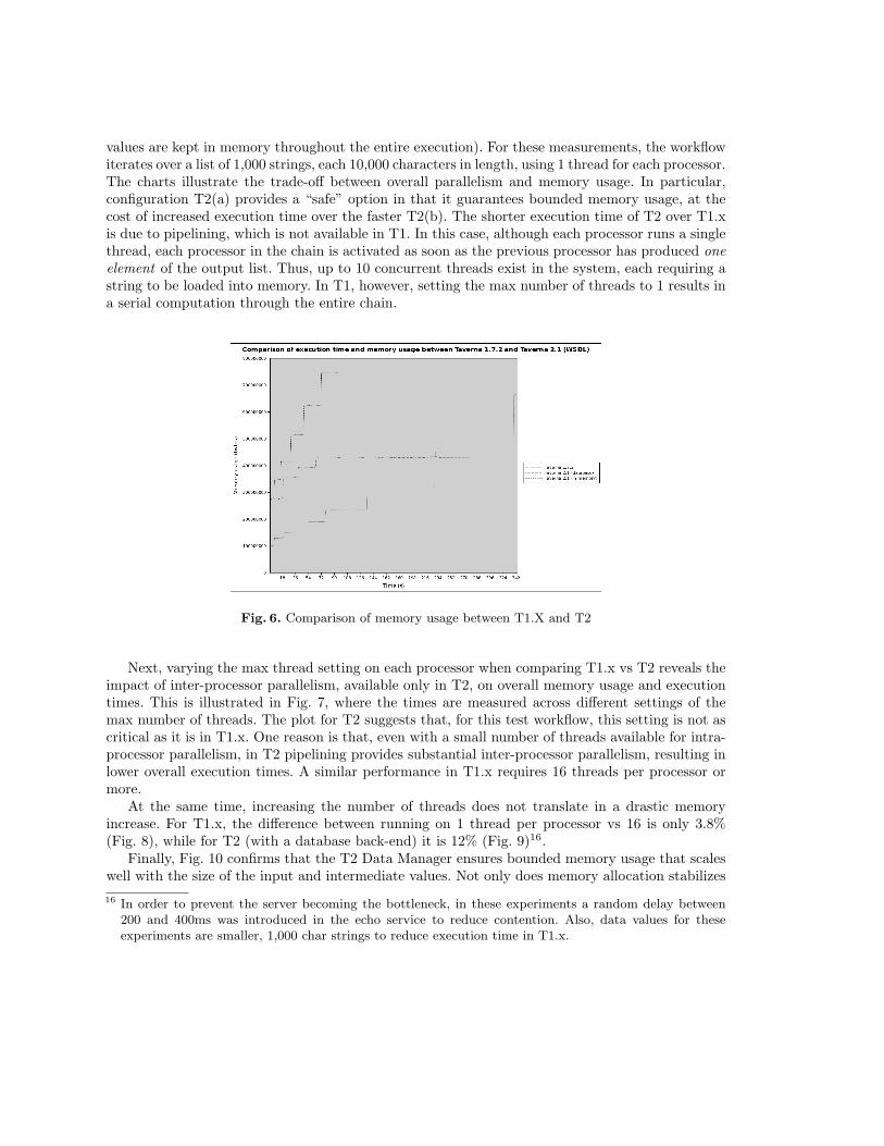
values are kept in memory throughout the entire execution). For these measurements, the workflowiterates over a list of 1,000 strings, each 10,000 characters in length, using 1 thread for each processor.The charts illustrate the trade-off between overall parallelism and memory usage. In particular,configuration T2(a) provides a “safe” option in that it guarantees bounded memory usage, at thecost of increased execution time over the faster T2(b). The shorter execution time of T2 over T1.xis due to pipelining, which is not available in T1. In this case, although each processor runs a singlethread, each processor in the chain is activated as soon as the previous processor has produced oneelement of the output list. Thus, up to 10 concurrent threads exist in the system, each requiring astring to be loaded into memory. In T1, however, setting the max number of threads to 1 results ina serial computation through the entire chain.
Fig. 6. Comparison of memory usage between T1.X and T2
Next, varying the max thread setting on each processor when comparing T1.x vs T2 reveals theimpact of inter-processor parallelism, available only in T2, on overall memory usage and executiontimes. This is illustrated in Fig. 7, where the times are measured across different settings of themax number of threads. The plot for T2 suggests that, for this test workflow, this setting is not ascritical as it is in T1.x. One reason is that, even with a small number of threads available for intra-processor parallelism, in T2 pipelining provides substantial inter-processor parallelism, resulting inlower overall execution times. A similar performance in T1.x requires 16 threads per processor ormore.
At the same time, increasing the number of threads does not translate in a drastic memoryincrease. For T1.x, the difference between running on 1 thread per processor vs 16 is only 3.8%(Fig. 8), while for T2 (with a database back-end) it is 12% (Fig. 9)16.
Finally, Fig. 10 confirms that the T2 Data Manager ensures bounded memory usage that scaleswell with the size of the input and intermediate values. Not only does memory allocation stabilizes
16 In order to prevent the server becoming the bottleneck, in these experiments a random delay between200 and 400ms was introduced in the echo service to reduce contention. Also, data values for theseexperiments are smaller, 1,000 char strings to reduce execution time in T1.x.

Fig. 7. Comparison of execution times between T1.X and T2 with varying thread limits
Fig. 8. T1.x memory usage for different “max thread” processor settings
as the execution progresses, but, importantly, this is true across a range of data sizes that vary byan order of magnitude.
7 Case study: performance of a caGrid workflow
Taverna is the workflow model of choice for the caGrid project [25], which provides a service-basedinfrastructure consisting of data and computation resources designed to assist in-silico scientificinvestigation in cancer research [12]. As a specific case study, in this section we compare the perfor-mance of T2 against T1.x using a caGrid production workflow17 used to carry out cancer diagnosisbased on microarray analysis [16]. The workflow begins by extracting hybridization data, obtained
17 The workflow, not reproduced here due to space constraints, is available from the myExperiment website, at http://www.myexperiment.org/workflows/746.

Fig. 9. T2 memory usage for different “max thread” processor settings
from samples that belong to two different lymphoma types, from a microarray database. The datais then normalized and used to learn a classification model for lymphoma type prediction, usingthe Support Vector Machine (SVM) and K-Nearest Neighbour (KNN) algorithms. The model canthen be used to classify lymphoma types from an unknown microarray dataset.
Our observations confirm the insight provided by the results presented in the previous section,regarding the time/memory trade-off available in T2. Specifically, Fig. 11 shows similar executiontimes (380sec. for T1.x and 450sec for T2 with a similar total number of threads, 40 vs 47), butbetter memory management for T2. The main difference between the two execution models is thatT2 resolves references to microarray datasets, each about 10MB in size, on demand, transferringthem from disk to process space and flushing them after use. This makes better use of memory butinvolves additional disk transfers. The in-memory model of T1.x saves transfer time but results inunbound memory usage.
As a second experiment aimed at showing the effect of pipelining, we have monitored the exe-cution time and memory usage under different settings of max threads per processor, for a portionof the same caGrid workflow consisting of a linear chain of processors (Fig. 12), which are made toiterate over an input list of 10 experiment IDs. The results, shown in Fig. 13, indicate a near-linearcorrelation between max-thread setting on the processors and execution time, up to 10 threads perprocessor. A higher number of threads would bring diminishing returns, however, since the amountof real concurrency available on the Java-based workflow engine is limited by the number of coresthat the JVM can use (2, in this experiment), and at the same time those threads saturate theconcurrent server where the Web services execute, making it a bottleneck.
8 Conclusions
We have presented the salient architectural features of the Taverna 2 workflow management system,which make it both more scalable and extensible than its predecessor. These features include, amongothers: (i) a runtime environment in which the available intra- and inter-processor parallelism thatare implicit in the dataflow model are exposed as multiple execution threads; (ii) extensibility andconfigurability points based on the interceptor pattern; (iii) openness to thrid party service types,

Fig. 10. Memory usage in T2 for different input strings lengths
based on a Service Provider Interface model, and (iv) a two-tier data architecture that separatesthe data space from the workflow enactment space. We have exploited the extensible dispatch stackby adding custom layers to add control constructs, such as a while-loop and if-then-else, to theworkflow model.
Our performance results, measured on a suite of programmatically generated workflows thatexhibit both processor iteration and pipelining, indicate that T2 with a database-based Data Man-ager offers good control of workflow execution memory while exhibiting competitive execution time.Furthermore, when pipelining can be exploited, the performance is not sensitive to the size of thethread pool available to each processor.
Finally, we have presented a concrete case study that highlights the memory usage / executiontime trade-offs on a production workflow from the caGrid project.
References
1. Peter Couvares, Tevfik Kosar, Alain Roy, Jeff Weber, and Kent Wenger. Workflows for e-Science,chapter Workflow Management in Condor. Springer, 2007.
2. Jeffrey Dean and Sanjay Ghemawat. MapReduce: Simplified Data Processing on Large Clusters. InOSDI, pages 137–150, 2004.
3. Ewa Deelman, Scott Callaghan, Edward Field, Hunter Francoeur, Robert Graves, Nitin Gupta, VipinGupta, Thomas Jordan, Carl Kesselman, Philip Maechling, John Mehringer, Gaurang Mehta, DavidOkaya, Karan Vahi, and Li Zhao. Managing Large-Scale Workflow Execution from Resource Provision-ing to Provenance Tracking: The CyberShake Example. In e-Science, page 14, 2006.
4. Ewa Deelman and Ann L Chervenak. Data Management Challenges of Data-Intensive Scientific Work-flows. In CCGRID, pages 687–692, 2008.
5. Ewa Deelman, Gurmeet Singh, Mei-Hui Su, James Blythe, Yolanda Gil, Carl Kesselman, GaurangMehta, Karan Vahi, G Bruce Berriman, John Good, Anastasia C Laity, Joseph C Jacob, and Daniel SKatz. Pegasus: A framework for mapping complex scientific workflows onto distributed systems. Sci-entific Programming, 13(3):219–237, 2005.

Fig. 11. Memory footprints for the lymphoma workflow in T1.X and T2
6. P. Fisher, C. Hedeler, K. Wolstencroft, H. Hulme, H. Noyes, S. Kemp, R. Stevens, and A. Brass. A sys-tematic strategy for large-scale analysis of genotype phenotype correlations: identification of candidategenes involved in African trypanosomiasisafrican trypanosomiasis. Nucleic Acids Research, 35(16):5625–33, Aug 2007.
7. Ian T. Foster, Jens-S. Vockler, Michael Wilde, and Yong Zhao. Chimera: Avirtual data system forrepresenting, querying, and automating data derivation. In SSDBM, pages 37–46. IEEE ComputerSociety, 2002.
8. D. Georgakopoulos, H. Schuster, D. Baker, and A. Cichocki. Managing escalation of collaborationprocesses in crisis mitigation situations. In Data Engineering, 2000. Proceedings. 16th InternationalConference on, pages 45–56, 2000.
9. Y. Gil, E. Deelman, M. Ellisman, T. Fahringer, G. Fox, D. Gannon, C. Goble, M. Livny, L. Moreau,and J. Myers. Examining the challenges of scientific workflows. Computer, 40(12):24–32, Dec. 2007.
10. D. Hull, K. Wolstencroft, R. Stevens, C. A. Goble, M. R. Pocock, P. Li, and T. Oinn. Taverna: a toolfor building and running workflows of services. Nucleic Acids Research, 34(Web-Server-Issue):729–732,2006.
11. K. Hwang and F. A. Briggs. Computer architecture and parallel processing. McGraw-Hill, New York,1986.
12. S Joel, K Tahsin, H Shannon, L Stephen, and O Scott Et al. e-Science, caGrid, and TranslationalBiomedical Research. Computer, 41:58–66, 2008.
13. E. A. Lee. Dataflow process networks. Memorandum UCB/ERL M94/53, UC Berkeley EECS Dept,1994.
14. E. A. Lee and A. Sangiovanni-Vincentelli. Comparing models of computation. In ICCAD ’96: Pro-ceedings of the 1996 IEEE/ACM international conference on Computer-aided design, pages 234–241,Washington, DC, USA, 1996. IEEE Computer Society.
15. P. Li, J. Castrillo, G. Velarde, I. Wassink, S. Soiland-Reyes, S. Owen, D. Withers, T. Oinn, M. Pocock,C. Goble, S. Oliver, and D. Kell. Performing statistical analyses on quantitative data in taverna work-flows: an example using R and maxdBrowse to identify differentially-expressed genes from microarraydata. BMC Bioinformatics, 9(334), August 2008.
16. M. A. Shipp, K N Ross, P Tamayo, A P Weng, J L Kutok, and R C T Aguiar. Diffuse large B-celllymphoma outcome prediction by gene-expression profiling and supervised machine learning. NatureMedicine, 8:68–74, 2002.
17. Paolo Missier, Norman Paton, and Khalid Belhajjame. Fine-grained and efficient lineage querying ofcollection-based workflow provenance. In Procs. EDBT, Lausanne, Switzerland, 2010.

Fig. 12. Pipelined portion of the lym-phoma workflow
threadpool size
exec time(sec)
maxmemory(MB)
maxthreadcount
1 41 317 47
1 29 317 47
5 24 383 55
10 21 442 56
Fig. 13. Execution times and memory usage bythread pool size
18. T. Oinn, M. Addis, J. Ferris, D. Marvin, M. Senger, M. Greenwood, T. Carver, K. Glover, M. R.Pocock, A. l Wipat, and P. Li. Taverna: a tool for the composition and enactment of bioinformaticsworkflows. Bioinformatics, 20(17):3045–3054, 2004.
19. C. Pautasso and G. Alonso. Parallel computing patterns for grid workflows. In Proc. of the HPDC2006Workshop on Workflows in Support of Large-Scale Science (WORKS06), Paris, France, 2006.
20. D. Smedley, S. Haider, B. Ballester, R. Holland, D. London, G. Thorisson, and A. Kasprzyk. Biomart– biological queries made easy. BMC Genomics, 10(22), 2009.
21. Jacek Sroka, Jan Hidders, Paolo Missier, and Carole Goble. Formal semantics for the taverna 2 workflowmodel. Journal of Computer and System Sciences, 2009.
22. Wei Tan, Ravi Madduri, Kiran Keshav, Baris E. Suzek, Scott Oster, and Ian Foster. Orchestrating cagridservices in taverna. The 2008 IEEE International Conference on Web Services (ICWS 2008),Beijing,China (Accepted), September 2008.
23. D. Turi, P. Missier, D. De Roure, C. Goble, and T. Oinn. Taverna Workflows: Syntax and Semantics.In Proceedings of the 3rd e-Science conference, Bangalore, India, December 2007.
24. Wil M. P. van der Aalst, Arthur H. M. ter Hofstede, Bartek Kiepuszewski, and Alistair P. Barros.Workflow patterns. Distributed and Parallel Databases, 14(1):5–51, 2003.
25. W. Tan I. Foster and R Madduri. Combining the Power of Taverna and caGrid: Scientific Workflowsthat Enable Web-Scale Collaboration. IEEE Internet Computing, 12:61–68, 2008.
26. Edward Walker, Weijia Xu, and Vinoth Chandar. Composing and executing parallel data-flow graphswith shell pipes. In WORKS ’09: Proceedings of the 4th Workshop on Workflows in Support of Large-Scale Science, pages 1–10, New York, NY, USA, 2009. ACM.
27. Jianwu Wang, Daniel Crawl, and Ilkay Altintas. Kepler + Hadoop: a general architecture facilitatingdata-intensive applications in scientific workflow systems. In WORKS ’09: Proceedings of the 4thWorkshop on Workflows in Support of Large-Scale Science, pages 1–8, New York, NY, USA, 2009.ACM.