tbm drives in squeezing ground – shield-rock interaction · pdf filetbm drives in...
TRANSCRIPT
Institute for Geotechnical EngineeringTunnelling and Rock Engineering Group
Marco Ramoni & Georg Anagnostou Institute for Geotechnical Engineering, ETH Zurich, Switzerland
"TBM drives in squeezing ground – Shield-rock interaction"
AFTES International Congress Monaco Grimaldi Forum, Montecarlo, Monaco – 6-8 October 2008
Reference: Ramoni M. & Anagnostou G. (2008): TBM drives in squeezing rock - Shield-rock interaction; Building underground for the future; AFTES International Congress Monaco, Montecarlo; 163-172; Edition specifique Limonest.
TBM drives in squeezing ground – Shield-rock interaction
Avancement avec TBM dans des roches poussantes – Interaction bouclier-roche
Marco Ramoni, Research Assistant, ETH Zurich, Switzerland
Georgios Anagnostou, Professor, ETH Zurich, Switzerland
Address of the Authors
MSc ETH/SIA Marco Ramoni ETH Zurich, Institute for Geotechnical Engineering, Tunnelling and Rock Engineering Research Group
HIL D14.3, POB 133, Wolfgang-Pauli-Strasse 15, CH-8093 Zurich
Prof. Dr. Georgios Anagnostou ETH Zurich, Institute for Geotechnical Engineering, Tunnelling and Rock Engineering Research Group
HIL D14.3, POB 133, Wolfgang-Pauli-Strasse 15, CH-8093 Zurich
ABSTRACT: This paper investigates the risk of TBM immobilization in squeezing ground. We identify the relevant factors, outline possible counter-measures and analyze quantitatively the effect of the advance rate, of the duration of a possible standstill, of the ground permeabil-ity, of the shield length and of the installed thrust force by means of numerical calculations. The drive of deep, long tunnels with variable geological conditions calls for mechanized tunneling at the limit of TBM applicability. This paper analyses the problems concerning TBM drives in weak ground with emphasis to the phenomenon of squeezing. Squeezing ground in tunneling is associated with large deforma-tions of the tunnel perimeter and of the tunnel face and may therefore cause a series of difficulties such as sticking of the cutter head or jamming of the shield, extensive convergences of the bored profile or destruction of the tunnel support. These difficulties, alone or in com-bination with other ones, may slow down or even obstruct TBM operation and, if occurring over frequent tunnel intervals or persisting over longer portions of a tunnel, may have a decisive effect on the economic viability and on the feasibility of a TBM drive. From tunneling prac-tice it is well-known that squeezing is a time-dependent process which may take place over a period of days, weeks or months. The time-dependency can be traced back to the rheological properties of the ground (creep) and to the pore water pressure dissipation in the case of water bearing, low-permeability ground (consolidation). These two mechanisms are in general superimposed on the spatial stress redistri-bution taking place in the vicinity of the advancing face. Although cases are also known of intense and rapid deformations close to the tun-nel heading, squeezing deformations normally develop slowly. The risk of jamming depends therefore essentially on the TBM advance rate or on the duration of standstills. RÉSUMÉ: Cet article étudie le risque d'immobilisation de TBM dans des roches poussantes. Nous identifions les facteurs déterminants, décrivons des mesures constructives qui peuvent être utilisées et analysons quantitativement l'effet de la vitesse d'avancement, de la du-rée d'un éventuel arrêt de l'excavation, de la perméabilité du terrain, de la longueur du bouclier et de la force de poussée installée avec de calculs numériques. L'excavation d'un tunnel long et profond est souvent accomplie en utilisant une TBM. En raison des conditions géolo-giques variables, il est possible que la TBM doive être utilisée jusqu'à ses limites. Cet article analyse les problèmes concernant l'avance-ment en terrain faible avec TBM, mettant l'accent sur le phénomène des roches poussantes. La construction d'un tunnel dans des roches poussantes est associée à de larges déformations du front de taille et du périmètre du tunnel qui peuvent causer une série de difficultés comme un blocage de la tête de forage ou du bouclier, des convergences considérables ou même la destruction du soutènement. Ces dif-ficultés, seules ou en association avec d'autres, peuvent ralentir ou même empêcher le fonctionnement d'une TBM. Si elles surviennent fréquemment ou de manière persistante sur de longues portions d'un tunnel, elles peuvent avoir un effet décisif sur la viabilité économique et technique d'une excavation mécanisée. Des expériences pratiques vécues, il est bien connu que le phénomène des roches poussantes est un processus dépendant du temps, qui peut se dérouler sur une période de plusieurs jours, semaines ou mois. La dépendance du temps peut être attribuée aux propriétés rhéologiques du sol (fluage) et à la dissipation des pressions de l'eau interstitielle, dans le cas des terrains aquifère à faible perméabilité (consolidation). Ces deux mécanismes sont en général superposés à la redistribution spatiale de tensions qui se déroule à proximité du front de taille. Bien que des cas soient aussi connus où les déformations ont été intenses et rapides près de la tête de forage, normalement, dans le cas de roche poussante, les déformations se développent lentement. Le risque de blocage de la TBM dépend donc essentiellement de la vitesse d'avancement de la TBM ou de la durée d'arrêt de service.
1 – INTRODUCTION The construction of new infrastructures for the intercity people and goods traffic often requires the excavation of long, deep tunnels. In order to reduce the construction time and, in some cases, even to allow an economically justifiable realization of these underground structures, the use of tunnel boring machines (TBMs) is aimed. Due to alignment constraints and – particularly for long, deep tunnels – limitations of the geological exploration, it is not always possible to avoid difficult geological zones with sufficient reliability. In some cases, even the limits of applicability of the TBM can be reached. If occurring over frequent tunnel intervals or persisting over longer portions of a tunnel these difficulties may be decisive for the economic viability and the feasibility of a TBM drive. TBM performance can be affected by the geological conditions in a great variety of ways. In hard rock, for example, boreability problems may occur such as a low penetration rate or excessive wear necessitating frequent cutter changes or maintenance work. Mixed face or blocky rock conditions may cause steering difficulties or severe vibrations lead-
ing to considerable wear or even damage to the cutter head. Water inflows may affect mucking efficiency or the installation of a seg-mental lining. A series of difficulties are associated with a low strength or high deformability ground and, in a wider sense, fall under the heading of "stability and deformation problems". Low strength ground, such as highly fractured or weathered rock, may lead to cave-ins ahead of the tunnel face or to blockage of the cutter head. In open-type TBMs difficulties with the support installation or the gripper positioning may also occur as a conse-quence of instabilities of the excavation walls. Particularly challenging is the crossing of fault zones with soil-like material under high water pressures (Anagnostou & Kovári 2005). When such a zone is suddenly encountered, water and loose material flows into the opening. In some cases the fault zones are accompanied laterally by a heavily jointed and fractured rock, in other cases the transition to competent rock is very distinct. During driving operation it is absolutely essential to recognize such zones early by advance probing. To overcome fault zones involv-ing soil-like ground under water pressure, the ground is drained
and strengthened ahead of the working face. Both the identification and the treatment of such zones may reduce TBM utilization con-siderably. When driving through zones of highly deformable ground the tunnelling engineer is faced with problems of a completely different kind. If suitable preventive measures are not implemented, large long-term deformations of the opening occur, which may lead even to a complete closure of the tunnel cross section. The rock exerts a gradually increasing pressure on the lining, which may lead to its damage or even its complete destruction. In such cases one speaks of "genuine rock pressure" and the ground is characterized as "squeezing ground" (Kovári 1998). Experience shows that large rock deformations and large rock pressures occur only in weak rocks with a high deformability and a low strength, often in combi-nation with a high overburden. Typical examples of such rocks are phyllite, schist, serpentinite, claystone, certain types of Flysch and decomposed clay and micaceous rocks (Barla 2001, Kovári & Staus 1996). Experience also shows that a high pore water pres-sure promotes the development of squeezing. Squeezing ground conditions may slow down or even obstruct TBM operation and even question the feasibility of a TBM drive. It should also be noted, nevertheless, that the difficulties associated with squeezing often arise in combination with the instability phe-nomena mentioned above. In several cases a feedback between the different problems may be observed (Kovári 1986a). This paper discusses the specific problems of mechanized tunnelling in squeezing ground, with particular emphasis on the problem of shield jamming (Section 2), on the time-dependency of squeezing (Section 3), on understanding the mechanisms govern-ing the ground response to tunnelling operations and on some practical questions of mechanized tunnelling through water bearing squeezing ground (Section 4). At the end of this paper some other considerations related to a case history will be illustrated (Sec-tion 5). 2 – SPECIFIC PROBLEMS OF TBM DRIVES IN SQUEEZ-ING GROUND TBM performance is the result of an interaction between the ma-chine, the tunnel support and the ground. The latter may be con-sidered as "given", because improvement measures such as drainage are time-consuming and stay therefore in conflict with the goal of attaining a high advance rate. Furthermore, the feasibility and effectiveness of such measures strongly depends on the ground characteristics and has to be checked in each particular case. The potential hazards associated with squeezing ground con-cern both the machine (sticking of the cutter head, jamming of the shield) and the back-up area (inadmissible convergences of the bored profile, damage to the support). The problems in the back-up area are basically the same as in conventional tunnelling, the main difference being that in conventional tunnelling one can excavate a considerably larger profile in order to allow for large deformations. Due to the fixed geometry and the limited flexibility of the TBM, the space available for ground deformations and support is largely pre-
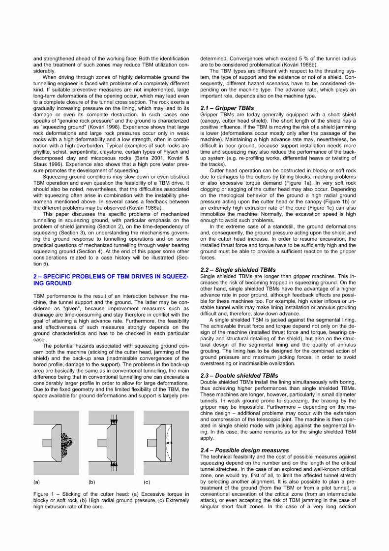
determined. Convergences which exceed 5 % of the tunnel radius are to be considered problematical (Kovári 1986b). The TBM types are different with respect to the thrusting sys-tem, the type of support and the existence or not of a shield. Con-sequently, different hazard scenarios have to be considered de-pending on the machine type. The advance rate, which plays an important role, depends also on the machine type. 2.1 – Gripper TBMs Gripper TBMs are today generally equipped with a short shield (canopy, cutter head shield). The short length of the shield has a positive influence. If the TBM is moving the risk of a shield jamming is lower (deformations occur mostly only after the passage of the machine). Maintaining a high advance rate may, nevertheless, be difficult in poor ground, because support installation needs more time and squeezing may also reduce the performance of the back-up system (e.g. re-profiling works, differential heave or twisting of the tracks). Cutter head operation can be obstructed in blocky or soft rock due to damages to the cutters by falling blocks, mucking problems or also excessive torque demand (Figure 1a). In very soft rock clogging or sagging of the cutter head may also occur. Depending on the rheological behavior of the ground a high radial ground pressure acting upon the cutter head or the canopy (Figure 1b) or an extremely high extrusion rate of the core (Figure 1c) can also immobilize the machine. Normally, the excavation speed is high enough to avoid such problems. In the extreme case of a standstill, the ground deformations and, consequently, the ground pressure acting upon the shield and on the cutter head increase. In order to resume excavation, the installed thrust force and torque have to be sufficiently high and the ground must be able to provide a sufficient reaction to the gripper forces. 2.2 – Single shielded TBMs Single shielded TBMs are longer than gripper machines. This in-creases the risk of becoming trapped in squeezing ground. On the other hand, single shielded TBMs have the advantage of a higher advance rate in poor ground, although feedback effects are possi-ble for these machines too. For example, high water inflows or un-stable tunnel walls may make lining installation or annulus grouting difficult and, therefore, slow down advance. A single shielded TBM is jacked against the segmental lining. The achievable thrust force and torque depend not only on the de-sign of the machine (installed thrust force and torque, bearing ca-pacity and structural detailing of the shield), but also on the struc-tural design of the segmental lining and the quality of annulus grouting. The lining has to be designed for the combined action of ground pressure and maximum jacking forces, in order to avoid overstressing or inadmissible ovalization. 2.3 – Double shielded TBMs Double shielded TBMs install the lining simultaneously with boring, thus achieving higher performances than single shielded TBMs. These machines are longer, however, particularly in small diameter tunnels. In weak ground prone to squeezing, the bracing by the gripper may be impossible. Furthermore – depending on the ma-chine design – additional problems may occur with the extension and compression of the telescopic joint. The machine is then oper-ated in single shield mode with jacking against the segmental lin-ing. In this case, the same remarks as for the single shielded TBM apply. 2.4 – Possible design measures The technical feasibility and the cost of possible measures against squeezing depend on the number and on the length of the critical tunnel stretches. In the case of an explored and well-known critical zone, one would try, first of all, to limit the affected tunnel stretch by selecting another alignment. It is also possible to plan a pre-treatment of the ground (from the TBM or from a pilot tunnel), a conventional excavation of the critical zone (from an intermediate attack), or even accepting the risk of TBM jamming in the case of singular short fault zones. In the case of a very long section
Figure 1 – Sticking of the cutter head: (a) Excessive torque inblocky or soft rock, (b) High radial ground pressure, (c) Extremely high extrusion rate of the core.
through squeezing ground, the possibility of selecting a larger bor-ing diameter for the whole tunnel can also be examined. The design of the TBM plays an important role. Improvements in TBM-technology allow the installation of higher thrust force and torque – of up to 150 MN and 30 MNm, respectively, for a Ø 10 m shielded TBM (Grandori 2006, Stahn & Grimm 2006) – and the reduction of the machine length also for double shielded TBMs (easier to realize for bigger diameters) up to a ratio machine length to boring diameter of about 1-2 (Estefania 2002, Grandori 2006). The shield can also be slightly "conical" by 2-4 cm in radius (Hemphill & Tempelis 2005, Lovat 1997). The friction between shield skin and ground can be reduced up to 50 % by lubricants such as bentonite (Gehring 1996). A moderate amount of squeezing can be accommodated by using extendable gauge cutters when such ground is encountered. This solution allows an increasing of the boring diameter up to 30 cm (Wolff & Goliasch 2003) and can be easily handled by grip-per TBMs; for shielded TBMs, lifting of the centerline of the shield is necessary (Voerckel 2001). For all TBM types a re-positioning of the mucking buckets is also needed (Schmid 2008). However the overboring technology is not yet well developed and its value is very uncertain at least for long reaches with squeezing conditions (ITA 2003). The trouble-free application of it seems to be possible only in very soft rocks. Another critical aspect is related with the timely decision making during construction. The determination of the right time-point for the begin of the complicated overboring pro-cedure is not easy under job site conditions. 3 – TIME-DEPENDENCY OF GROUND DEFORMATIONS 3.1 – Observations Experience shows that squeezing may take place over a period of days, weeks or months. Usually it is a slow process, although there have also been cases of intense and rapid development of ground deformations close to the working face. As an example, the "Strada"-section of the headrace tunnel Tavanasa-Ilanz in Switzerland can be mentioned. This tunnel crosses a phyllitic verrucano and was bored in the period 1985-1988 by a gripper TBM (Ø = 5.20 m). During the drive in an over-thrust zone, measurements revealed that within just a half day the convergence was greater than 25 cm, i.e. 5 % of the boring diame-ter (Marty 1989). Another interesting example is the water tunnel Evinos-Mornos in Greece. This tunnel crosses mainly Flysch and it was con-structed in the years 1993-1994 by two gripper TBMs (Ø = 4.20 m) and two double shielded TBMs (Ø = 4.04 m). During the gripper TBM drives through some thrust zones, the ground squeezed so rapidly that the radial displacements amounted 3-5 cm right at the cutter head and 5-8 cm at the location of support installation (Vigl & Jäger 1997). The double shielded TBMs encountered squeezing conditions in an overthrust zone which was more than 650 m long. Within less than one hour after the excavation, at a distance of only 2 m from the working face, the convergences reached 15 cm, i.e.
4.% of the boring diameter (Grandori & Antonini 1994, Grandori et al. 1995). The New Viola water tunnel (Italy) was constructed in the years 1999-2004 by a double shielded TBM (Ø = 3.60 m). The machine was trapped first during excavation in a phyllitic rock. The ground deformation was fast enough to close the gap (8 cm) around the shield (L = 9 m) within six to ten hours (Höfle 2001). The same machine was later stopped again because of squeezing ground, although this was after a one-week holiday stop. 3.2 – Mechanisms The gradual increase of the ground deformation or pressure is first of all a consequence of the spatial stress redistribution associated with progressive excavation (Lombardi 1973). The stress redistri-bution is completed within a relatively short distance from the face, and cannot therefore explain long-term phenomena but is, never-theless, essential for the convergence in the machine area and, consequently, for the loads acting upon the shield. Long-term deformations can be traced back to the creep and consolidation processes taking place in the ground surrounding the tunnel (Anagnostou & Kovári 1999). In the vicinity of the working face, creep and consolidation are in general superimposed on the spatial stress redistribution associated with the advancing excava-tion. Consolidation comes into play when tunnelling through a wa-ter-bearing, low-permeability ground. Creep depends on the rheological properties of the ground and becomes evident espe-cially when the ground is highly stressed as the state of failure is approached. It is therefore of great importance in the case of squeezing ground (Fritz 1981). In order to reduce complexity, creeping will not be considered further in this paper. Instead, atten-tion will be paid to the consolidation processes around the advanc-ing face. 3.3 – Pore water pressure generation and dissipation Squeezing is usually accompanied by a volume increase of the ground. The volume increase can be theoretically explained by the so-called "plastic dilatancy" of the ground (also referred to as "loosening" in tunnelling practice) and by the reduction of the stresses within the overstressed zone around the opening. As this volume increase is associated with an increase of the pore volume, squeezing of a saturated ground leads also to a rise in water con-tent. This occurs more or less rapidly depending on the permeabil-ity of the ground. In a low-permeability ground, the water content remains constant in the short term. Since the pore water hinders dilatancy, excess pore water pressures develop, which dissipate slowly over the course of time. Tunnel excavation in a saturated squeezing ground thus triggers a transient seepage flow process. Seepage flow and ground deformation are coupled to each other. The pore water pressures and the effective stresses change with time, the latter leading to additional deformations or, in the pres-ence of a lining, to increasing loading (Anagnostou & Kovári 2005). Two important limiting states of the transient process are the state at time t = 0+ ("short-term behavior") and the state at t = ∞
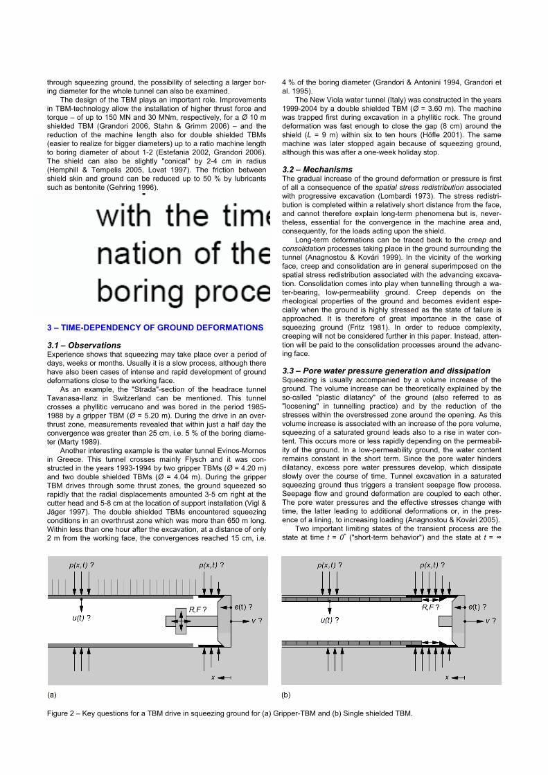
Figure 2 – Key questions for a TBM drive in squeezing ground for (a) Gripper-TBM and (b) Single shielded TBM.
("long-term behavior"). The first is characterized by the condition of a constant water content (so-called "undrained conditions"), while the second is governed by the steady state pore water pressure distribution (so-called "drained conditions"). According to theoreti-cal and experimental investigations (Vogelhuber 2007), the nega-tive excess pore pressures developing under undrained conditions strengthen the ground (so-called "dilatancy hardening"). The short-term behavior is therefore more favorable than the long-term beha-vior. During continuous tunnel excavation, consolidation takes place in general simultaneously with the stress redistribution caused by the advancing tunnel heading. In the case of rapid excavation through a low-permeability ground, the favourable "undrained con-ditions" prevail in the vicinity of the advancing face. If the excava-tion proceeds slowly or the permeability of the ground is high, the unfavourable "drained conditions" prevail practically right from the start. A simple dimensional analysis shows that the ratio of ad-vance rate v to ground permeability k is decisive for the time de-velopment of the ground deformations close to the tunnel face (Anagnostou 2007). The same mechanisms govern the ground behavior in the course of an excavation standstill. If the drained conditions have not been reached already during the preceding continuous excava-tion (i.e. if the advance rate was high enough or the ground per-meability low), consolidation will continue during the standstill pe-riod until reaching the steady state pore pressure distribution. Due to the change of the effective stresses, the ground will deform and the rock pressure will increase over time. The higher the advance rate during the preceding excavation, the more the conditions pre-vailing at the begin of standstill will deviate from the drained condi-tions and, consequently, the more time must elapse until reaching a steady state. So, rapid excavation is advantageous also with re-spect to a subsequent standstill, whether the latter is intended or not. 4 – NUMERICAL INVESTIGATIONS For the evaluation of the feasibility of a TBM drive and for the de-sign of the TBM, a series of questions must be investigated con-cerning the ground pressure p (acting upon the cutter head, the shield and the lining), the deformations of the tunnel wall u and of the tunnel face e, the needed thrust force F and torque and the resulting reaction forces R (Figure 2). As explained above, all these parameters depend also on the advance rate v or on the du-ration of a standstill. Besides the experiences from projects with comparable geo-logical conditions, numerical analyses are helpful for evaluating the potential hazards as they provide indications of the magnitude of the key parameters. In the following sections, the problem of shield jamming, the effects of possible countermeasures and, more gen-erally, the shield-rock interaction will be analyzed. The numerical investigations are based on an axially symme-tric model. The ground is modelled as a saturated porous medium accord-ing to the principle of effective stresses. Seepage flow is taken into
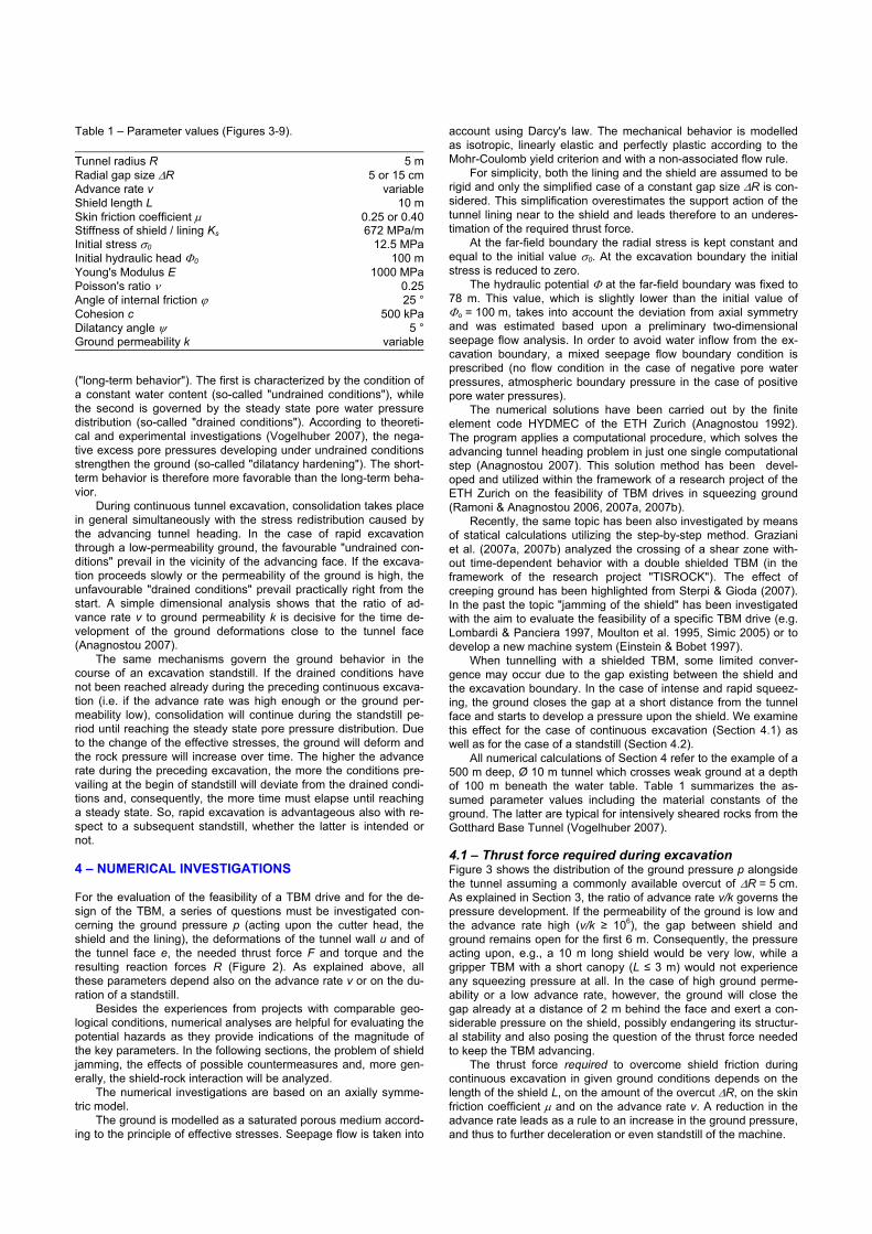
account using Darcy's law. The mechanical behavior is modelled as isotropic, linearly elastic and perfectly plastic according to the Mohr-Coulomb yield criterion and with a non-associated flow rule. For simplicity, both the lining and the shield are assumed to be rigid and only the simplified case of a constant gap size ΔR is con-sidered. This simplification overestimates the support action of the tunnel lining near to the shield and leads therefore to an underes-timation of the required thrust force. At the far-field boundary the radial stress is kept constant and equal to the initial value σ0. At the excavation boundary the initial stress is reduced to zero. The hydraulic potential Φ at the far-field boundary was fixed to 78 m. This value, which is slightly lower than the initial value of Φo = 100.m, takes into account the deviation from axial symmetry and was estimated based upon a preliminary two-dimensional seepage flow analysis. In order to avoid water inflow from the ex-cavation boundary, a mixed seepage flow boundary condition is prescribed (no flow condition in the case of negative pore water pressures, atmospheric boundary pressure in the case of positive pore water pressures). The numerical solutions have been carried out by the finite element code HYDMEC of the ETH Zurich (Anagnostou 1992). The program applies a computational procedure, which solves the advancing tunnel heading problem in just one single computational step (Anagnostou 2007). This solution method has been devel-oped and utilized within the framework of a research project of the ETH Zurich on the feasibility of TBM drives in squeezing ground (Ramoni & Anagnostou 2006, 2007a, 2007b). Recently, the same topic has been also investigated by means of statical calculations utilizing the step-by-step method. Graziani et al. (2007a, 2007b) analyzed the crossing of a shear zone with-out time-dependent behavior with a double shielded TBM (in the framework of the research project "TISROCK"). The effect of creeping ground has been highlighted from Sterpi & Gioda (2007). In the past the topic "jamming of the shield" has been investigated with the aim to evaluate the feasibility of a specific TBM drive (e.g. Lombardi & Panciera 1997, Moulton et al. 1995, Simic 2005) or to develop a new machine system (Einstein & Bobet 1997). When tunnelling with a shielded TBM, some limited conver-gence may occur due to the gap existing between the shield and the excavation boundary. In the case of intense and rapid squeez-ing, the ground closes the gap at a short distance from the tunnel face and starts to develop a pressure upon the shield. We examine this effect for the case of continuous excavation (Section 4.1) as well as for the case of a standstill (Section 4.2). All numerical calculations of Section 4 refer to the example of a 500 m deep, Ø 10 m tunnel which crosses weak ground at a depth of 100 m beneath the water table. Table 1 summarizes the as-sumed parameter values including the material constants of the ground. The latter are typical for intensively sheared rocks from the Gotthard Base Tunnel (Vogelhuber 2007). 4.1 – Thrust force required during excavation Figure 3 shows the distribution of the ground pressure p alongside the tunnel assuming a commonly available overcut of ΔR = 5 cm. As explained in Section 3, the ratio of advance rate v/k governs the pressure development. If the permeability of the ground is low and the advance rate high (v/k ≥ 106), the gap between shield and ground remains open for the first 6 m. Consequently, the pressure acting upon, e.g., a 10 m long shield would be very low, while a gripper TBM with a short canopy (L ≤ 3 m) would not experience any squeezing pressure at all. In the case of high ground perme-ability or a low advance rate, however, the ground will close the gap already at a distance of 2 m behind the face and exert a con-siderable pressure on the shield, possibly endangering its structur-al stability and also posing the question of the thrust force needed to keep the TBM advancing. The thrust force required to overcome shield friction during continuous excavation in given ground conditions depends on the length of the shield L, on the amount of the overcut ΔR, on the skin friction coefficient μ and on the advance rate v. A reduction in the advance rate leads as a rule to an increase in the ground pressure, and thus to further deceleration or even standstill of the machine.
Table 1 – Parameter values (Figures 3-9).
Tunnel radius R 5 mRadial gap size ΔR 5 or 15 cmAdvance rate v variableShield length L 10 mSkin friction coefficient μ 0.25 or 0.40Stiffness of shield / lining Ks 672 MPa/mInitial stress σ0 12.5 MPaInitial hydraulic head Φ0 100 mYoung's Modulus E 1000 MPaPoisson's ratio ν 0.25Angle of internal friction ϕ 25 °Cohesion c 500 kPaDilatancy angle ψ 5 °Ground permeability k variable
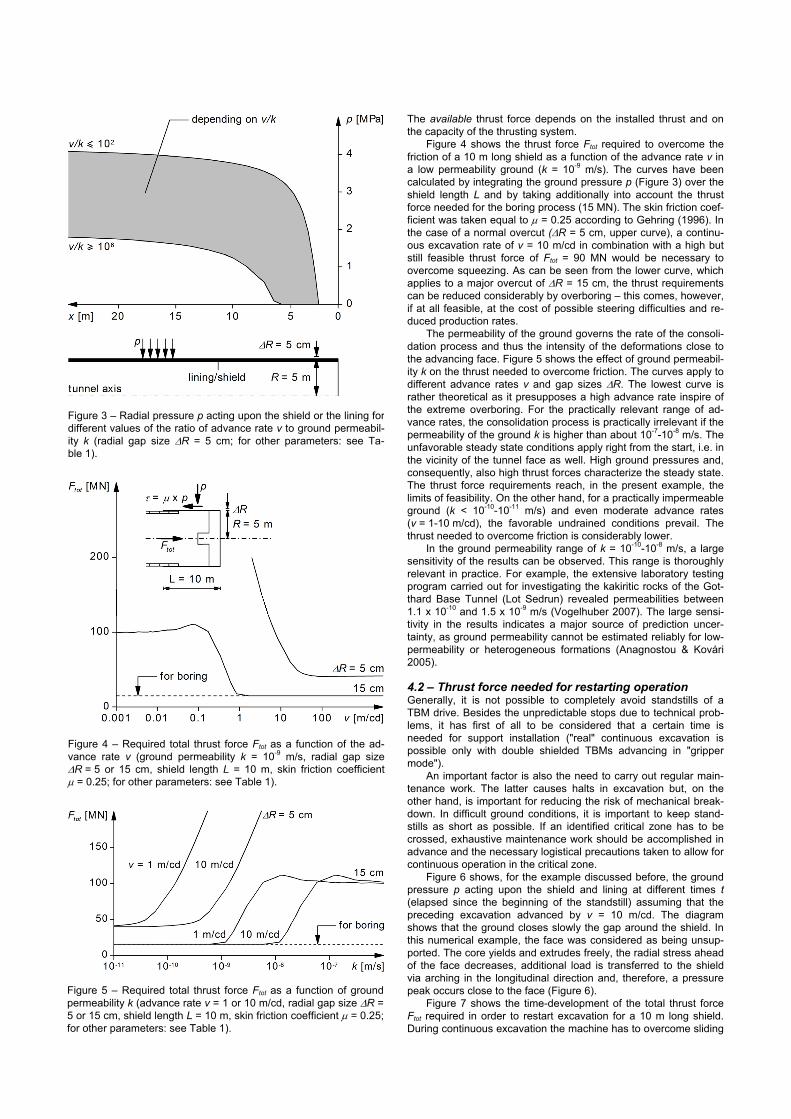
The available thrust force depends on the installed thrust and on the capacity of the thrusting system. Figure 4 shows the thrust force Ftot required to overcome the friction of a 10 m long shield as a function of the advance rate v in a low permeability ground (k = 10-9 m/s). The curves have been calculated by integrating the ground pressure p (Figure 3) over the shield length L and by taking additionally into account the thrust force needed for the boring process (15 MN). The skin friction coef-ficient was taken equal to μ = 0.25 according to Gehring (1996). In the case of a normal overcut (ΔR = 5 cm, upper curve), a continu-ous excavation rate of v = 10 m/cd in combination with a high but still feasible thrust force of Ftot = 90 MN would be necessary to overcome squeezing. As can be seen from the lower curve, which applies to a major overcut of ΔR = 15 cm, the thrust requirements can be reduced considerably by overboring – this comes, however, if at all feasible, at the cost of possible steering difficulties and re-duced production rates. The permeability of the ground governs the rate of the consoli-dation process and thus the intensity of the deformations close to the advancing face. Figure 5 shows the effect of ground permeabil-ity k on the thrust needed to overcome friction. The curves apply to different advance rates v and gap sizes ΔR. The lowest curve is rather theoretical as it presupposes a high advance rate inspire of the extreme overboring. For the practically relevant range of ad-vance rates, the consolidation process is practically irrelevant if the permeability of the ground k is higher than about 10-7-10-8 m/s. The unfavorable steady state conditions apply right from the start, i.e. in the vicinity of the tunnel face as well. High ground pressures and, consequently, also high thrust forces characterize the steady state. The thrust force requirements reach, in the present example, the limits of feasibility. On the other hand, for a practically impermeable ground (k < 10-10-10-11 m/s) and even moderate advance rates (v = 1-10 m/cd), the favorable undrained conditions prevail. The thrust needed to overcome friction is considerably lower. In the ground permeability range of k = 10-10-10-8 m/s, a large sensitivity of the results can be observed. This range is thoroughly relevant in practice. For example, the extensive laboratory testing program carried out for investigating the kakiritic rocks of the Got-thard Base Tunnel (Lot Sedrun) revealed permeabilities between 1.1 x 10⁻¹⁰ and 1.5 x 10⁻⁹ m/s (Vogelhuber 2007). The large sensi-tivity in the results indicates a major source of prediction uncer-tainty, as ground permeability cannot be estimated reliably for low-permeability or heterogeneous formations (Anagnostou & Kovári 2005). 4.2 – Thrust force needed for restarting operation Generally, it is not possible to completely avoid standstills of a TBM drive. Besides the unpredictable stops due to technical prob-lems, it has first of all to be considered that a certain time is needed for support installation ("real" continuous excavation is possible only with double shielded TBMs advancing in "gripper mode"). An important factor is also the need to carry out regular main-tenance work. The latter causes halts in excavation but, on the other hand, is important for reducing the risk of mechanical break-down. In difficult ground conditions, it is important to keep stand-stills as short as possible. If an identified critical zone has to be crossed, exhaustive maintenance work should be accomplished in advance and the necessary logistical precautions taken to allow for continuous operation in the critical zone. Figure 6 shows, for the example discussed before, the ground pressure p acting upon the shield and lining at different times t (elapsed since the beginning of the standstill) assuming that the preceding excavation advanced by v = 10 m/cd. The diagram shows that the ground closes slowly the gap around the shield. In this numerical example, the face was considered as being unsup-ported. The core yields and extrudes freely, the radial stress ahead of the face decreases, additional load is transferred to the shield via arching in the longitudinal direction and, therefore, a pressure peak occurs close to the face (Figure 6). Figure 7 shows the time-development of the total thrust force Ftot required in order to restart excavation for a 10 m long shield. During continuous excavation the machine has to overcome sliding
Figure 3 – Radial pressure p acting upon the shield or the lining fordifferent values of the ratio of advance rate v to ground permeabil-ity k (radial gap size ΔR = 5 cm; for other parameters: see Ta-ble 1).
Figure 4 – Required total thrust force Ftot as a function of the ad-vance rate v (ground permeability k = 10-9 m/s, radial gap sizeΔR = 5 or 15 cm, shield length L = 10 m, skin friction coefficient μ = 0.25; for other parameters: see Table 1).
Figure 5 – Required total thrust force Ftot as a function of ground permeability k (advance rate v = 1 or 10 m/cd, radial gap size ΔR = 5 or 15 cm, shield length L = 10 m, skin friction coefficient μ = 0.25; for other parameters: see Table 1).
friction, while directly after the TBM-stop (t = 0) static friction be-comes relevant. Therefore, a higher skin-friction coefficient μ was considered (0.40 instead of 0.25, Gehring 1996). In the case of a major overboring (ΔR = 15 cm), the gap between shield and ground remains open for a certain period. The ground starts to ex-ert a pressure upon the shield only after 5 days, while reaching steady state conditions takes about 50 days. The required thrust
force may increase to the level of the available thrust force after a certain period of time. Figure 8 shows the influence of ground permeability k on the critical standstill duration tcrit under the assumptions that the ad-vance rate was v = 10 m/cd before the standstill and that the avail-able thrust force amounts to 150 MN – a high, but still feasible value (Grandori 2006, Stahn & Grimm 2006). The higher the per-meability of the ground, the shorter the critical standstill duration will be. For ground permeabilities higher than about k = 10-9 m/s and a normal overcut of ΔR = 5 cm, the critical standstill duration tcrit decreases rapidly to zero: at this ground permeability range, the required thrust force was close to the available one already during the previous continuous excavation that proceeded with v = 10 m/cd. However, as explained in Section 3, the conditions prevailing at the beginning of a standstill will depend on the advance rate dur-ing the previous TBM operation: for a given ground permeability k, the higher the advance rate v, the lower the total required thrust force Ftot will be during excavation (Figure 4) and, therefore, the more time must elapse during a standstill in order that the required thrust force reaches the available one (Figure 9). If the standstill was caused by an excessive ground pressure acting upon the shield during excavation, the restart of the TBM will be even more difficult. 5 – APPLICATION 5.1 – Introduction As a practical application example, the case of a tunnel with severe squeezing phenomena will be discussed in this section. The tunnel has a diameter of 5 m and is currently under construction. Excava-tion is carried out by a single shielded TBM. The shield is 12 m long and the installed thrust force amounts to 30 MN. The ground is of Triassic origin and consists of a claystone matrix containing 1-50 cm big sandstone lenses. The claystone fraction amounts to about 80 %. The claystones are intensively sheared, have several slickensides and disintegrate quickly under the action of water. Laboratory results revealed an angle of internal friction ϕ of about 20 º, strongly variable cohesion values (c = 50-400 kPa) and a Young's Modulus E of 200-1000 MPa. During the past TBM operation, squeezing caused jamming of the shield on several occasions although the depth of cover of about 120 m is rather moderate. The available monitoring results are very sparse, but some observations indicate a large variability of the squeezing intensity and maximum deformation rates of up to 60 mm/hour. We carried out a comprehensive parametric study in order to improve understanding for the observed phenomena, to analyze the factors influencing the jamming of the TBM and to evaluate the effectiveness of possible technical improvements. Section 5.2 pre-sents some results of this study, while Section 5.3 discusses in more detail the shield-ground interaction in short critical zones consisting of weak ground. 5.2 – TBM-drive in homogenous ground The calculations have been carried out under the assumption that time-effects are associated only with the spatial stress-redistribution around the advancing heading, i.e. consolidation or creep processes have not been taken into account. This simplifying assumption is safe with respect to the problem under considera-tion, as it leads to an upper limit of the pressure acting upon the shield. Furthermore, due to the low strength of the encountered ground, the assumption was made that the force needed for the boring process is so small, that it can be neglected in the thrust force calculations. The skin friction coefficient μ was taken equal to 0.50. This value is relevant for the static friction conditions prevail-ing during excavation restart after a stop for the installation of the segmental lining and has been taken after Gehring (1996). For a given overburden and given TBM parameters (Table 2) a critical range of rock mass parameters can be determined beyond which jamming occurs. The critical ground conditions for an over-burden of H = 120 m and for different values of the overcut ΔR are represented by combinations of the Young's modulus E and the cohesion c in Figure 10 (all the others ground parameters have
Figure 6 – Radial pressure p acting upon the shield or the lining atdifferent times t during standstill (advance rate before standstill v = 10 m/cd, ground permeability k = 10-9 m/s, radial gap sizeΔR = 5 or 15 cm; for other parameters: see Table 1).
Figure 7 – Required total thrust force Ftot as a function of the stand-still length t (advance rate before standstill v = 10 m/cd, groundpermeability k = 10-9 m/s, radial gap size ΔR = 5 or 15 cm, shieldlength L = 10 m, skin friction coefficient μ = 0.25 or 0.40 for con-tinuous excavation or standstill, respectively; for other parameters:see Table 1).
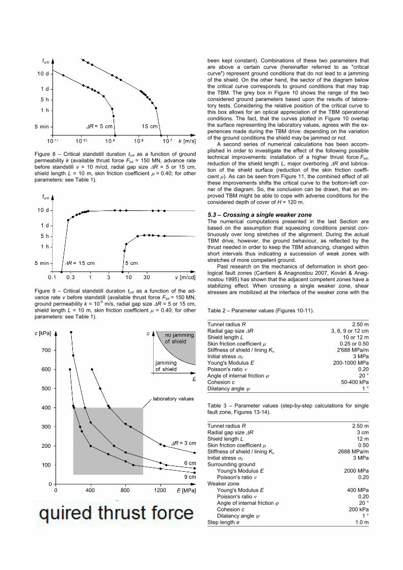
been kept constant). Combinations of these two parameters that are above a certain curve (hereinafter referred to as "critical curve") represent ground conditions that do not lead to a jamming of the shield. On the other hand, the sector of the diagram below the critical curve corresponds to ground conditions that may trap the TBM. The grey box in Figure 10 shows the range of the two considered ground parameters based upon the results of labora-tory tests. Considering the relative position of the critical curve to this box allows for an optical appreciation of the TBM operational conditions. The fact, that the curves plotted in Figure 10 overlap the surface representing the laboratory values, agrees with the ex-periences made during the TBM drive: depending on the variation of the ground conditions the shield may be jammed or not. A second series of numerical calculations has been accom-plished in order to investigate the effect of the following possible technical improvements: installation of a higher thrust force Ftot, reduction of the shield length L, major overboring ΔR and lubrica-tion of the shield surface (reduction of the skin friction coeffi-cient μ). As can be seen from Figure 11, the combined effect of all these improvements shifts the critical curve to the bottom-left cor-ner of the diagram. So, the conclusion can be drawn, that an im-proved TBM might be able to cope with adverse conditions for the considered depth of cover of H = 120 m. 5.3 – Crossing a single weaker zone The numerical computations presented in the last Section are based on the assumption that squeezing conditions persist con-tinuously over long stretches of the alignment. During the actual TBM drive, however, the ground behaviour, as reflected by the thrust needed in order to keep the TBM advancing, changed within short intervals thus indicating a succession of weak zones with stretches of more competent ground. Past research on the mechanics of deformation in short geo-logical fault zones (Cantieni & Anagnostou 2007, Kovári & Anag-nostou 1995) has shown that the adjacent competent zones have a stabilizing effect. When crossing a single weaker zone, shear stresses are mobilized at the interface of the weaker zone with the
Figure 8 – Critical standstill duration tcrit as a function of groundpermeability k (available thrust force Ftot = 150 MN, advance ratebefore standstill v = 10 m/cd, radial gap size ΔR = 5 or 15 cm,shield length L = 10 m, skin friction coefficient μ = 0.40; for otherparameters: see Table 1).
Figure 9 – Critical standstill duration tcrit as a function of the ad-vance rate v before standstill (available thrust force Ftot = 150 MN, ground permeability k = 10-9 m/s, radial gap size ΔR = 5 or 15 cm,shield length L = 10 m, skin friction coefficient μ = 0.40; for otherparameters: see Table 1).
Figure 10 – Critical ground conditions for an available thrust forceof Ftot = 30 MN (radial gap size ΔR = 3, 6 or 9 cm, shield length L = 12 m, skin friction coefficient μ = 0.50, safety factor for the re-quired thrust force SF = 2.0, for other parameters: see Table 2).
Table 2 – Parameter values (Figures 10-11).
Tunnel radius R 2.50 mRadial gap size ΔR 3, 6, 9 or 12 cmShield length L 10 or 12 mSkin friction coefficient μ 0.25 or 0.50Stiffness of shield / lining Ks 2'688 MPa/mInitial stress σ0 3 MPaYoung's Modulus E 200-1000 MPaPoisson's ratio ν 0.20Angle of internal friction ϕ 20 °Cohesion c 50-400 kPaDilatancy angle ψ 1 °
Table 3 – Parameter values (step-by-step calculations for single fault zone, Figures 13-14).
Tunnel radius R 2.50 mRadial gap size ΔR 3 cmShield length L 12 mSkin friction coefficient μ 0.50Stiffness of shield / lining Ks 2688 MPa/mInitial stress σ0 3 MPaSurrounding ground Young's Modulus E 2000 MPa Poisson's ratio ν 0.20Weaker zone Young's Modulus E 400 MPa Poisson's ratio ν 0.20 Angle of internal friction ϕ 20 ° Cohesion c 200 kPa Dilatancy angle ψ 1 °Step length e 1.0 m
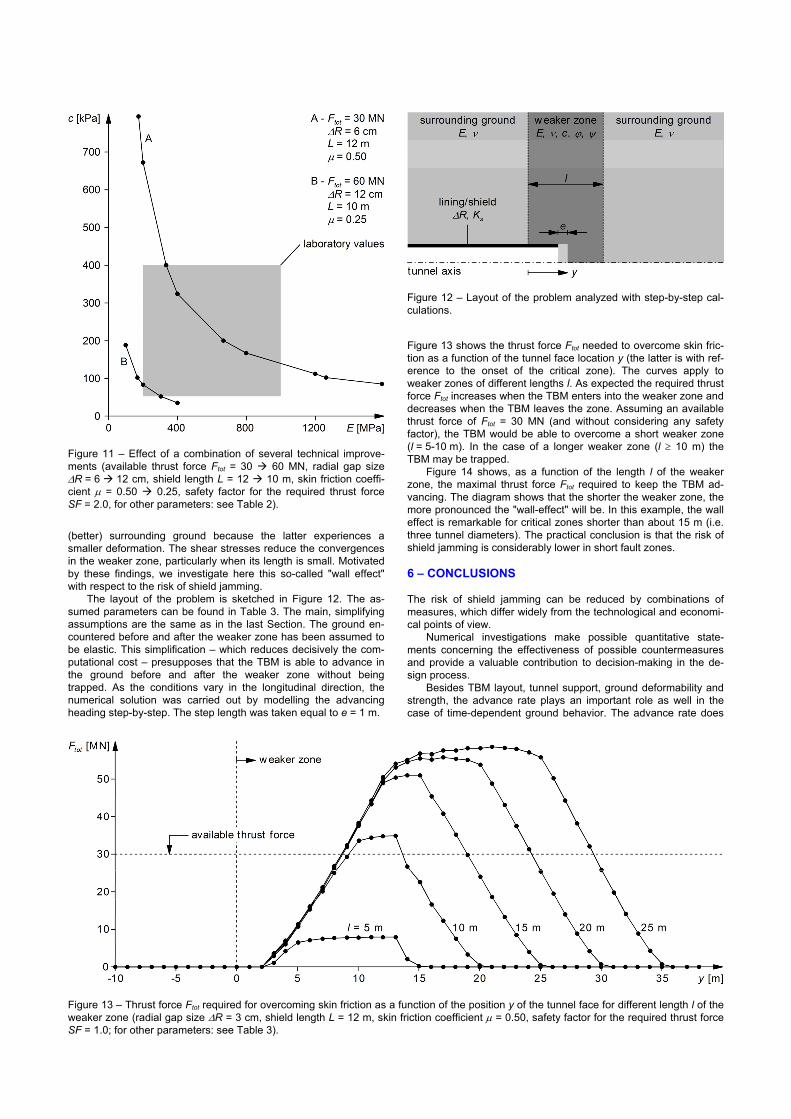
(better) surrounding ground because the latter experiences a smaller deformation. The shear stresses reduce the convergences in the weaker zone, particularly when its length is small. Motivated by these findings, we investigate here this so-called "wall effect" with respect to the risk of shield jamming. The layout of the problem is sketched in Figure 12. The as-sumed parameters can be found in Table 3. The main, simplifying assumptions are the same as in the last Section. The ground en-countered before and after the weaker zone has been assumed to be elastic. This simplification – which reduces decisively the com-putational cost – presupposes that the TBM is able to advance in the ground before and after the weaker zone without being trapped. As the conditions vary in the longitudinal direction, the numerical solution was carried out by modelling the advancing heading step-by-step. The step length was taken equal to e = 1 m.
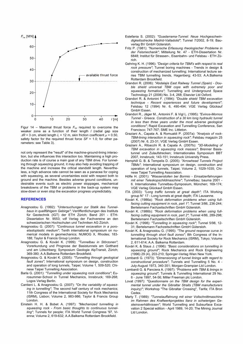
Figure 13 shows the thrust force Ftot needed to overcome skin fric-tion as a function of the tunnel face location y (the latter is with ref-erence to the onset of the critical zone). The curves apply to weaker zones of different lengths l. As expected the required thrust force Ftot increases when the TBM enters into the weaker zone and decreases when the TBM leaves the zone. Assuming an available thrust force of Ftot = 30 MN (and without considering any safety factor), the TBM would be able to overcome a short weaker zone (l = 5-10 m). In the case of a longer weaker zone (l ≥ 10 m) the TBM may be trapped. Figure 14 shows, as a function of the length l of the weaker zone, the maximal thrust force Ftot required to keep the TBM ad-vancing. The diagram shows that the shorter the weaker zone, the more pronounced the "wall-effect" will be. In this example, the wall effect is remarkable for critical zones shorter than about 15 m (i.e. three tunnel diameters). The practical conclusion is that the risk of shield jamming is considerably lower in short fault zones. 6 – CONCLUSIONS The risk of shield jamming can be reduced by combinations of measures, which differ widely from the technological and economi-cal points of view. Numerical investigations make possible quantitative state-ments concerning the effectiveness of possible countermeasures and provide a valuable contribution to decision-making in the de-sign process. Besides TBM layout, tunnel support, ground deformability and strength, the advance rate plays an important role as well in the case of time-dependent ground behavior. The advance rate does
Figure 11 – Effect of a combination of several technical improve-ments (available thrust force Ftot = 30 60 MN, radial gap sizeΔR = 6 12 cm, shield length L = 12 10 m, skin friction coeffi-cient μ = 0.50 0.25, safety factor for the required thrust forceSF = 2.0, for other parameters: see Table 2).
Figure 13 – Thrust force Ftot required for overcoming skin friction as a function of the position y of the tunnel face for different length l of the weaker zone (radial gap size ΔR = 3 cm, shield length L = 12 m, skin friction coefficient μ = 0.50, safety factor for the required thrust force SF = 1.0; for other parameters: see Table 3).
Figure 12 – Layout of the problem analyzed with step-by-step cal-culations.
not only represent the "result" of the machine-ground-lining interac-tion, but she influences this interaction too. Maintaining a high pro-duction rate is of course a main goal of any TBM drive. For tunnel-ing through squeezing ground, it may also help avoiding trapping of the machine and increase the critical standstill length. Neverthe-less, a high advance rate cannot be seen as a panacea for coping with squeezing, as several uncertainties exist with respect both to ground and the machine. Besides adverse ground conditions, un-desirable events such as electric power stoppages, mechanical breakdowns of the TBM or problems in the back-up system may slow-down or even stop the excavation progress unpredictably. REFERENCES Anagnostou G. (1992): "Untersuchungen zur Statik des Tunnel-
baus in quellfähigem Gebirge"; Veröffentlichungen des Instituts für Geotechnik (IGT) der ETH Zürich; Band 201 - ETH-Dissertation Nr. 9553; vdf Verlag der Fachvereine an den schweizerischen Hochschulen und Techniken AG Zürich.
Anagnostou G. (2007): "Continuous tunnel excavation in a poro-elastoplastic medium"; Tenth international symposium on nu-merical models in geomechanics; NUMOG X, Rhodes; 183-188; Taylor & Francis Group London.
Anagnostou G. & Kovári K. (1999): "Tunnelbau in Störzonen"; Vorerkundung und Prognose der Basistunnels am Gotthard und am Lötschberg; Symposium Geologie AlpTransit, Zürich; 369-380; A.A.Balkema Rotterdam Brookfield.
Anagnostou G. & Kovári K. (2005): "Tunnelling through geological fault zones"; International symposium on design, construction and operation of long tunnels, Taipei; Volume 1, 509-520; Chi-nese Taipei Tunnelling Association.
Barla G. (2001): "Tunnelling under squeezing rock conditions"; Eu-rosummer-School in Tunnel Mechanics, Innsbruck; 169-268; Logos Verlag Berlin.
Cantieni L. & Anagnostou G. (2007): "On the variability of squeez-ing in tunnelling"; The second half century of rock mechanics; 11th Congress of the International Society for Rock Mechanics (ISRM), Lisbon; Volume 2, 983-986; Taylor & Francis Group London.
Einstein H. H. & Bobet A. (1997): "Mechanized tunnelling in squeezing rock - From basic thoughts to continuous tunnel-ling"; Tunnels for people; ITA World Tunnel Congress '97, Vi-enna; Volume 2, 619-632; A.A.Balkema Rotterdam Brookfield.
Estefania S. (2002): "Guadarrama-Tunnel: Neue Hochgeschwin-digkeitsstrecke Madrid-Valladolid"; Tunnel 7/2002, 8-19; Bau-verlag BV GmbH Gütersloh.
Fritz P. (1981): "Numerische Erfassung rheologischer Probleme in der Felsmechanik"; Mitteilung Nr. 47 - ETH-Dissertation Nr. 6848; Institut für Strassen-, Eisenbahn- und Felsbau - ETH Zü-rich.
Gehring K. H. (1996): "Design criteria for TBM's with respect to real rock pressure"; Tunnel boring machines - Trends in design & construction of mechanized tunnelling; International lecture se-ries TBM tunnelling trends, Hagenberg; 43-53; A.A.Balkema Rotterdam Brookfield.
Grandori R. (2006): "Abdalajis East Railway Tunnel (Spain) - Dou-ble shield universal TBM cope with extremely poor and squeezing formations"; Tunnelling and Underground Space Technology 21 (2006) No. 3-4, 268; Elsevier Ltd Oxford.
Grandori R. & Antonini F. (1994): "Double shield TBM excavation technique - Recent experiences and future development"; Felsbau 12 (1994) Nr. 6, 490-494; VGE Verlag Glückauf GmbH Essen.
Grandori R., Jäger M., Antonini F. & Vigl L. (1995): "Evinos-Mornos Tunnel - Greece. Construction of a 30 km long hydraulic tunnel in less than three years under the most adverse geological conditions"; Rapid Excavation and Tunnelling Conference, San Francisco; 747-767; SME Inc. Littleton.
Graziani A., Capata A. & Romualdi P. (2007a): "Analysis of rock-TBM-lining interaction in squeezing rock"; Felsbau magazin 25 (2007) Nr. 6, 23-31; VGE Verlag GmbH Essen.
Graziani A., Ribacchi R. & Capata A. (2007b): "3D-Modelling of TBM excavation in squeezing rock masses"; Brenner Basis-tunnel und Zulaufstrecken; Internationales Symposium BBT 2007, Innsbruck; 143-151; Innsbruck University Press.
Hemphill G. B. & Tempelis D. (2005): "Arrowhead Tunnels Project TBMs"; International symposium on design, construction and operation of long tunnels, Taipei; Volume 2, 1029-1035; Chi-nese Taipei Tunnelling Association.
Höfle H. (2001): "Wasserstollen bei Bormio - Einsatzerfahrungen mit einer Teleskopschildmaschine"; Tunnelbau; bauma 2001 - 6. Internationales Tunnelbau-Symposium, München; 169-174; VGE Verlag Glückauf GmbH Essen.
ITA (2003): "Long traffic tunnels at great depth"; ITA Working group N° 17 - Long tunnels at great depth; ITA Lausanne.
Kovári K. (1986a): "Rock deformation problems when using full-facing cutting equipment in rock, part 1"; Tunnel 3/86, 236-244; Bertelsmann Fachzeitschriften GmbH Gütersloh.
Kovári K. (1986b): "Rock deformation problems when using full-facing cutting equipment in rock, part 2"; Tunnel 4/86, 289-298; Bertelsmann Fachzeitschriften GmbH Gütersloh.
Kovári K. (1998): "Tunnelling in squeezing rock"; Tunnel 5/98, 12-31; Bertelsmann Fachzeitschriften GmbH Gütersloh.
Kovári K. & Anagnostou G. (1995): "The ground response curve in tunnelling through short fault zones"; 8th Congress of the In-ternational Society for Rock Mechanics (ISRM), Tokyo; Volume 2, 611-614; A.A. Balkema Rotterdam.
Kovári K. & Staus J. (1996): "Basic considerations on tunnelling in squeezing ground"; Rock Mechanics and Rock Engineering (1996) 29 (4), 203-210; Springer-Verlag Wien New York.
Lombardi G. (1973): "Dimensioning of tunnel linings with regard to constructional procedure"; Tunnels and Tunnelling 5 No. 4 - July-August 1973, 340-351; Morgan-Grampian Ltd London.
Lombardi G. & Panciera A. (1997): "Problems with TBM & linings in squeezing ground"; Tunnels & Tunnelling International 29 No. 6 - June 1997, 54-56; Miller Freeman plc London.
Lovat (1997): "Questionnaire on the TBM design for the experi-mental tunnel under the Gibraltar Straits (TBM manufacturers inquiry)"; Workshop "The Gibraltar Crossing", Tarifa; ITA Bron Cedex.
Marty T. (1989): "Tunnelauffahrung mit einer Vollschnittmaschine im Rahmen des Kraftwerkprojektes Ilanz in schwierigen Ge-steinsverhältnissen"; World Tunnelling and Subsurface Exca-vation 2 Special edition - April 1989, 14-20; The Mining Journal Ltd London.
Figur 14 – Maximal thrust force Ftot required to overcome theweaker zone as a function of their length l (radial gap sizeΔR = 3 cm, shield length L = 12 m, skin friction coefficient μ = 0.50, safety factor for the required thrust force SF = 1.0; for other pa-rameters: see Table 3).
Moulton B. G., Cass D. T., Nowak D. E. & Poulin R. M. (1995): "Tunnel boring machine concept for converging ground"; Rapid Excavation and Tunnelling Conference, San Francisco; 509-523; SME Inc. Littleton.
Ramoni M. & Anagnostou G. (2006): "On the feasibility of TBM drives in squeezing ground"; Tunnelling and Underground Space Technology 21 (2006) No. 3-4, 262; Elsevier Ltd Oxford.
Ramoni M. & Anagnostou G. (2007a): "The effect of advance rate on shield loading in squeezing ground"; Underground space - The 4th dimension of metropolises; ITA World Tunnel Con-gress 2007, Prague; Volume 1, 673-677; Taylor & Francis Group London.
Ramoni M. & Anagnostou G. (2007b): "Numerical analysis of the development of squeezing pressure during TBM standstills"; The second half century of rock mechanics; 11th Congress of the International Society for Rock Mechanics (ISRM), Lisbon; Volume 2, 963-966; Taylor & Francis Group London.
Schmid L. (2008): "Personal communication"; March 2008. Simic D. (2005): "Tunnels de Guadarrama - Problématique des
tunnels profonds. La traversée de la faille de la Umbria du tun-nel de Guadarrama"; Tunnels et ouvrages souterrains N° 190 - Supplement Juillet/Aout 2005, 13-21; AFTES Paris.
Stahn C. & Grimm K. (2006): "Der Wienerwaldtunnel - Eine tunnel-bautechnische Herausforderung"; geotechnik 29 (2006) Nr. 2, 167-172; VGE Verlag Glückauf GmbH Essen.
Sterpi D. & Gioda G. (2007): "Ground pressure and convergence for TBM driven tunnels in visco-plastic rocks"; ECCOMAS The-matic conference on computational methods in tunnelling; EURO:TUN 2007, Vienna; 89; Vienna University of Technol-ogy.
Vigl L. & Jäger M. (1997): "Double shield TBM and open TBM in squeezing rock - A comparison"; Tunnels for people; ITA World Tunnel Congress '97, Vienna; Volume 2, 639-643; A.A.Balkema Rotterdam Brookfield.
Voerckel M. (2001): "Tunnelling with TBM - State of the art and future development"; Progress in tunnelling after 2000; ITA World Tunnel Congress 2001, Milan; Volume II, 493-500; Pàtron Editore Bologna.
Vogelhuber M. (2007): "Der Einfluss des Porenwasserdrucks auf das mechanische Verhalten kakiritisierter Gesteine"; Veröffent-lichungen des Instituts für Geotechnik (IGT) der ETH Zürich; Band 230 - ETH Dissertation Nr. 17079; vdf Hochschulverlag AG Zürich.
Wolff W. & Goliasch R. (2003): "Überschneideinrichtungen auf Hartgesteins-TBM - Kritische Betrachtungen anhand der Erfah-rungen vom Lötschberg Basistunnel"; Felsbau 21 (2003) Nr. 5, 147-154; VGE Verlag Glückauf GmbH Essen.