tcp/ip interface module
TRANSCRIPT

Manual No: 577013-776 Revision: D
Installation Guide
TCP/IP Interface Module

Notice
Veeder-Root makes no warranty of any kind with regard to this publication, including, but not limited to, theimplied warranties of merchantability and fitness for a particular purpose.
Veeder-Root shall not be liable for errors contained herein or for incidental or consequential damages inconnection with the furnishing, performance, or use of this publication.
Veeder-Root reserves the right to change system options or features, or the information contained in thispublication.
This publication contains proprietary information which is protected by copyright. All rights reserved. No partof this publication may be photocopied, reproduced, or translated to another language without the prior writtenconsent of Veeder-Root.
DAMAGE CLAIMS
1. Thoroughly examine all components and units as soon as they are received. If damaged, write a completeand detailed description of the damage on the face of the freight bill. The carrier's agent must verify theinspection and sign the description.
2. Immediately notify the delivering carrier of damage or loss. This notification may be given either in personor by telephone. Written confirmation must be mailed within 48 hours. Railroads and motor carriers arereluctant to make adjustments for damaged merchandise unless inspected and reported promptly.
3. Risk of loss, or damage to merchandise remains with the buyer. It is the buyer's responsibility to file a claimwith the carrier involved.
RETURN SHIPPING
For the parts return procedure, please follow the appropriate instructions in the "General Returned GoodsPolicy" and "Parts Return" pages in the "Policies and Literature" section of the Veeder-Root North AmericanEnvironmental Products price list.
©Veeder-Root 2004. All rights reserved.

Table of Contents
i
Table of Contents
IntroductionGeneral .............................................................................................................................1TCP/IP Interface Requirements ........................................................................................1TCP/IP Kits .......................................................................................................................1Contractor Certification Requirements ..............................................................................1Related Manuals ...............................................................................................................2Safety Precautions ............................................................................................................2
TCP/IP Interface Module InstallationVerifying TCP/IP Interface Module Configuration .............................................................3Installing the TCP/IP Interface Module in the Console .....................................................4
TLS-300/ProPlus Consoles ......................................................................................4TLS-350/ProMax Series Consoles ...........................................................................5
TCP/IP Interface Module Communication Setup ..............................................................7
TCP/IP Interface Module Initial ConnectionConnecting to the TCP/IP Interface Module Over a Network .................................10Connecting to the TCP/IP Interface Module Directly ..............................................11
TCP/IP Interface Module’s IP Address/Configuration Setup ...........................................15Entering the TCP/IP Interface Module’s IP Address...............................................15After Configuring The TCP/IP Module ....................................................................19
TCP/IP Interface Module Configuration Using A Web Browser ......................................19
FiguresFigure 1. TCP/IP interface module component locations .......................................3Figure 2. TLS-300/ProPlus Console battery backup switch location .....................4Figure 3. Installing TCP/IP module into TLS-300/ProPlus Console .......................5Figure 4. TLS-350/ProMax Series Console battery backup switch location ..........5Figure 5. TLS-350/ProMax Series TCP/IP module installation ..............................6Figure 6. Installing TCP/IP Module in TLS-350/ProMax Comm Bay Slot 4 ...........7Figure 7. Network connection ..............................................................................10Figure 8. Locating network connection/activity LEDs ..........................................10Figure 9. Direct connect using ethernet crossover cable .....................................11Figure 10. Network Screen ....................................................................................12Figure 11. TCP/IP Properties dialog box ...............................................................13Figure 12. Local Area Connection Status Screen ..................................................13Figure 13. Local Area Connection Properties Screen ............................................14Figure 14. Internet Protocol TCP/IP Properties dialog box ....................................14Figure 15. Telnet Setup Menu ...............................................................................16Figure 16. Web Browser Login ..............................................................................19Figure 17. Web Manager Interface ........................................................................20

Table of Contents
ii

1
Introduction
General
This manual contains procedures to install a TCP/IP Interface Module into the following consoles:
• Veeder-Root TLS-3XX Consoles
• Red Jacket ProPlus and ProMax Consoles
If this is a new installation or if site preparation is necessary, refer to the console’s Site Preparation and Installation manual, or contact your Veeder-Root representative for assistance.
TCP/IP Interface Requirements
Minimum system requirements for TCP/IP Interface Module operation are listed below:
• Console system software: Version 15 or higher - Version 21 or higher is recommended.
• Network connection to a PC requires a hub. Connecting to a hub requires a straight CAT 5 cable.
• Direct connection to a laptop requires an ethernet crossover cable.
• Connection to a LAN or WAN.
• Knowledge of networking.
TCP/IP Kits
• TLS-300/ProPlus Console Kit (P/N 330020-424):
- TCP/IP module (P/N 331871-001)
- #4-40 x 0.312” taptite screw - T-10 Torx drive (P/N 510500-414)
- Installation Guide (P/N 577013-776)
• TLS-350/ProMax Console Kit (P/N 330020-425):
- TCP/IP module (P/N 331870-001)
- Wiring harness (P/N 330584-001)
- Installation Guide (P/N 577013-776)
Contractor Certification Requirements
Veeder-Root requires the following minimum training certifications for contractors who will install and setup the equipment discussed in this manual:
Level 1 Contractors holding valid Level 1 Certification are approved to perform wiring and conduit routing, equipment mounting, probe and sensor installation, tank and line preparation, and line leak detector installation.

TLS RF Console Site Prep & Installation Manual Related Manuals
2
Level 2/3 Contractors holding valid Level 2 or 3 Certifications are approved to perform installation checkout, startup, programming and operations training, troubleshooting and servicing for all Veeder-Root Tank Monitoring Systems, including Line Leak Detection and associated accessories.
Warranty Registrations may only be submitted by selected Distributors.
Related Manuals
576013-623 TLS-3XX/ProPlus/ProMax Series System Setup Manual
576013-879 TLS-3XX/ProPlus/ProMax Series Consoles Site Prep and Installation Guide
Safety Precautions
The following safety symbols are used throughout this manual to alert you to important safety hazards and precautions.
EXPLOSIVEFuels and their vapors are extremely explosive if ignited.
ELECTRICITYHigh voltage exists in, and is supplied to, the device. A potential shock hazard exists.
TURN POWER OFFLive power to a device creates a potential shock hazard. Turn Off power to the device and associated accesso-ries when servicing the unit.
READ ALL RELATED MANUALSKnowledge of all related procedures before you begin work is important. Read and understand all manuals thoroughly. If you do not understand a procedure, ask some-one who does.
WARNINGYou are working with a device in which potentially lethal voltages may be present.Death or injury may result if safety precautions are not followed.
1. Read all instructions and warnings.
OFF

3
TCP/IP Interface Module Installation
Installation of the TCP/IP Interface module consists of:
1. Verifying the module’s configuration,
2. Installing the module in the TLS-300 Console (page 4) or the TLS-350 Console (page 5),
3. Setting up the module (page 7), and
4. Connecting the module to the local area network (page 15).
Verifying TCP/IP Interface Module Configuration
Key components of the TCP/IP Interface module are shown in Figure 1.
IMPORTANT! Write down the ethernet address from the label on the back of the TCP/IP board. You will need to enter this number for the TCP/IP board’s hardware address in “TCP/IP Interface Module’s IP Address/Configuration Setup” on page 15. Also record the rev of the board as it may be needed in setup.
Figure 1. TCP/IP interface module component locations
Legend for numbered boxes in Figure 1
1. End plate for TLS-300/ProPlus console TCP/IP module.2. RJ-45 Connector (typical both end plates)3. Reset button access (typical both plates)4. End plate for TLS-350/ProMax console TCP/IP module5. Network connection/activity LEDs (typical both end plates)6. J1 Connector7. J2 Jumper - Interrupt8. J3 Jumper - Chip Select9. Write down the ethernet address from the label on the LTRX XPort module (in this example, 00-20-4A-82-54-CD). You
will need this address for the TCP/IP module setup.10. Also record the rev number (in this example A11). It may be needed for the TCP/IP module setup.
RXGRN
TXRED
INT CL
RESET
J1
J3J2
cab&dim\tcpip2.eps
LTRX XPort
00-20-4A-82-54-CD
LTRX XPort
00-20-4A-82-54-CD
XPXXXXXXX-XXPatent Pending XXXXX
Rev. A11
1
2
3
4
5
6 7
8
109

TLS RF Console Site Prep & Installation Manual Installing the TCP/IP Interface Module in the Console
4
Installing the TCP/IP Interface Module in the Console
TLS-300/PROPLUS CONSOLES
1. Open the left door of the console (see Figure 2). Verify that the battery backup switch is in the On position, then turn Off power to the console.
2. Remove knockout blank from left bottom of console. Slide in the configured TCP/IP Interface Module until the motherboard connector is snugly seated and the left edge of the module’s bracket is in the notch cutout in the left side of the console. Attach securing screw from kit (see Figure 3). Leave the console door open.
Legend for numbered boxes in Figure 3
1. Battery backup switch (S1) shown in ‘On’ position (to left)
2. Remove knockout blank to install TCP/IP module.
3. Connector for TCP/IP module
Figure 2. TLS-300/ProPlus Console battery backup switch location
OFF
S2
S1
12
34
OP
EN
1
L
G
N
AC
NC
NO
C
2
NC
NO
C
1
RE
LA
Y+-
2
+-
1
INP
UT
BARRIERGROUND
RELAYRATINGS:
FORM CCONTACTS
120 VAC,2A Max; or24 VDC,2 A Max.
WARNING: TO INSUREINTRINSIC SAFETY,THIS COVER MUSTNOT BE REMOVED.
+1
WARNITHIS
3
2
1

TLS RF Console Site Prep & Installation Manual Installing the TCP/IP Interface Module in the Console
5
TLS-350/PROMAX SERIES CONSOLES
1. Open the left door of the console. Verify that the battery backup switch (SW1) is in the ‘On’ position (see Figure 4), then turn off power to the console.
Legend for numbered boxes in Figure 3
1. TX (red)
2. RX (green)
3. Bracket secured in notch
4. Remove blank in console base for access to module's plug-in connector
5. #4-40 x 0.312” taptite screw - T-10 Torx drive (P/N 510500-414)
6. Module bracket
7. Module plugs into male connector on motherboard
Figure 3. Installing TCP/IP module into TLS-300/ProPlus Console
Legend for numbered box in Figure 4
1. Battery backup switch (S1) shown in ‘On’ position (up).
Figure 4. TLS-350/ProMax Series Console battery backup switch location
cab&dim\tcpip300.eps
27
6
3
45
1
OFF
SW
2
SW
1
cab&dim\tcpip2fig3.eps
1 2 3 4
OPEN
1

TLS RF Console Site Prep & Installation Manual Installing the TCP/IP Interface Module in the Console
6
2. Installing the TCP/IP module in slots 1 - 3 (Preferred Location)
The TCP/IP module can be installed in any empty slot of the Comm Bay card cage, but the module’s default settings require that it be installed in slots 1 - 3.
If your console has a snap connector which secures the cover plate in the card cage, pull it out and lift out the cover plate. If your console has “knockout” cover plates, open the printer door and insert a flat blade screw driver in the slot provided in the front of the cover plate you are removing and twist it to break the front set of metal securing tabs (ref item 2 in Figure 5). Once the front tabs are broken, carefully move the loosened end of the plate up and down until the rear set of securing tabs break. Remove and discard the cover plate. Slide the module into the open slot until the motherboard connector is snugly seated. Do not apply excessive force when installing the module. With your thumb, push in the black retaining fastener on the end plate until it snaps into the hole in the card cage.
Installing the TCP/IP module in slot 4
If slots 1 - 3 are in use, or if you want to free up slots 1 - 3 for other modules, the TCP/IP module can be in-stalled in slot 4. To use slot 4, you must move jumpers J2 and J3 on the module onto the 2 top pins, and con-nect the cable from the kit (P/N 330584-001) to connector J1 on the module and to connector J5 on the console’s ECPU board (see Figure 6). Note: if the TCP/IP module is installed in slot 4, the displayed slot number (X) will be 5.
3. Verify that the RJ-45 plug in the module’s bracket is accessible through the slot opening in the bottom of the console.
Legend for numbered boxes in Figure 5
1. Comm bay card cage
2. Comm slot cover plate
3. Module slots 1 - 4
4. 24-pin board connector on TCP/IP module
Figure 5. TLS-350/ProMax Series TCP/IP module installation
cab&dim\tcpipins.eps
1 2 3 4
1
4 3 2

TLS RF Console Site Prep & Installation Manual TCP/IP Interface Module Communication Setup
7
4. When you are finished, make sure any unused slots in the comm cage have a blank end plate installed. Leave the console door open.
TCP/IP Interface Module Communication Setup
1. Close and secure the console front door. Restore power to the console.
2. You will need to know what version software is installed in the console to properly setup the TCP/IP module. Press the front panel MODE key to access Diag Mode. Press FUNCTION key to access System Diagnostic:
Press the STEP key to view the software revision level:
Legend for numbered boxes in Figure 5
1. J2/J3 jumper positions if installing TCP/IP module in slots 1-3 (default positions)
2. Move jumpers J2/J3 onto 2 top pins if installing TCP/IP module in slot 4
3. J1 connector4. Interconnecting cable from
the kit (P/N 330584-001)5. J5 on ECPU board
Figure 6. Installing TCP/IP Module in TLS-350/ProMax Comm Bay Slot 4
42 31
RXGRN
TXRED
INT CL
RESET
J1
J3J2
LTRX XPort
00-20-4A-82-54-CD
INT CL
J3J2
INT CL
J3J2
cab&dim\350tcpipins.eps
3 5
1
2
4
SYSTEM DIAGNOSTICPRESS <STEP> TO CONTINUE
SOFTWARE REVISION LEVELVERSION XYY.XX
TLS RF Console Site Prep & Installation Manual TCP/IP Interface Module Communication Setup
8
Where YY equals the console’s installed software. For example, if the version is 123.02, the software version is 23.
3. Press the front panel MODE key to access the Setup Mode. Press the FUNCTION key to access Communications Setup.
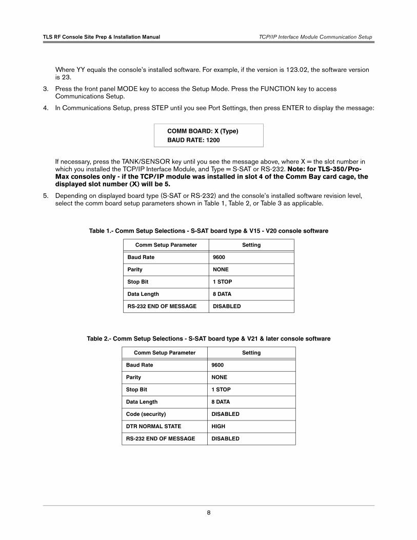
4. In Communications Setup, press STEP until you see Port Settings, then press ENTER to display the message:
If necessary, press the TANK/SENSOR key until you see the message above, where X = the slot number in which you installed the TCP/IP Interface Module, and Type = S-SAT or RS-232. Note: for TLS-350/Pro-Max consoles only - if the TCP/IP module was installed in slot 4 of the Comm Bay card cage, the displayed slot number (X) will be 5.
5. Depending on displayed board type (S-SAT or RS-232) and the console’s installed software revision level, select the comm board setup parameters shown in Table 1, Table 2, or Table 3 as applicable.
Table 1.- Comm Setup Selections - S-SAT board type & V15 - V20 console software
Comm Setup Parameter Setting
Baud Rate 9600
Parity NONE
Stop Bit 1 STOP
Data Length 8 DATA
RS-232 END OF MESSAGE DISABLED
Table 2.- Comm Setup Selections - S-SAT board type & V21 & later console software
Comm Setup Parameter Setting
Baud Rate 9600
Parity NONE
Stop Bit 1 STOP
Data Length 8 DATA
Code (security) DISABLED
DTR NORMAL STATE HIGH
RS-232 END OF MESSAGE DISABLED
COMM BOARD: X (Type)BAUD RATE: 1200

TLS RF Console Site Prep & Installation Manual TCP/IP Interface Module Communication Setup
9
Table 3.- Comm Setup Selections - RS-232 board type and V15 & later console software
Comm Setup Parameter Setting
Baud Rate 9600
Parity NONE
Stop Bit 1 STOP
Data Length 8 DATA
Code (security) DISABLED
RS-232 END OF MESSAGE DISABLED
10
TCP/IP Interface Module Initial Connection
After the TCP/IP Interface Module is installed and set up in the console, it can be connected to a PC in two ways:
• Over a network (LAN, WAN), or
• Directly
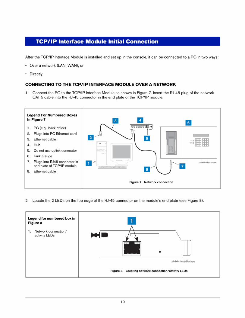
CONNECTING TO THE TCP/IP INTERFACE MODULE OVER A NETWORK
1. Connect the PC to the TCP/IP Interface Module as shown in Figure 7. Insert the RJ-45 plug of the network CAT 5 cable into the RJ-45 connector in the end plate of the TCP/IP module.
2. Locate the 2 LEDs on the top edge of the RJ-45 connector on the module’s end plate (see Figure 8).
Legend For Numbered Boxes In Figure 7
1. PC (e.g., back office)
2. Plugs into PC Ethernet card
3. Ethernet cable
4. Hub
5. Do not use uplink connector
6. Tank Gauge
7. Plugs into RJ45 connector in end plate of TCP/IP module
8. Ethernet cable
Figure 7. Network connection
Legend for numbered box in Figure 8
1. Network connection/activity LEDs
Figure 8. Locating network connection/activity LEDs
ALARM
WARNING
POWER
T1: PREMIUM UNLEADEDVOLUMEULLAGE90% ULLAGETC VOLUMEHEIGHTWATER VOLWATERTEMP
T1: REGULAR GASOLINEVOLUMEULLAGE90% ULLAGETC VOLUMEHEIGHTWATER VOLWATERTEMP
4208 GALS 5792 GALS 4792 GALS 4194 GALS41.02 INCHES 0 GALS 0.00 INCHES 65.0 DEG F
9038 GALS 962 GALS 0 GALS 8950 GALS81.37 INCHES 28 GALS 1.37 INCHES 74.9 DEG F
========
========
2
3
5
46
78
1 cab&dim\tcpipnc.eps
cab&dim\tcpip2led.eps
1

TLS RF Console Site Prep & Installation Manual TCP/IP Interface Module Communication Setup
11
Depending on network connection speed, the left or right LED on the top edge of the RJ-45 connector should remain ‘On’ when a proper connection is made (ref. Table 4).
After confirming a successful link between the PC and the TCP/IP module, go to “TCP/IP Interface Module’s IP Address/Configuration Setup” on page 15.
CONNECTING TO THE TCP/IP INTERFACE MODULE DIRECTLY
Connect the PC to the TCP/IP Interface Module as shown in Figure 9. Insert the RJ-45 plug of the ethernet crossover cable into the RJ-45 connector in the end plate of the TCP/IP Interface Module. Important! you must use an ethernet crossover cable.
Locate the 2 LEDs on the top edge of the RJ-45 connector on the module’s end plate (see Figure 8 on page 10).
Table 4.- Network Connection/Activity LED Codes (ref. view in Figure 8)
Left LED Right LED Meaning
Off Off No link
Off Solid amber 100Base-T half-duplex link
Off Blinking amber 100Base-T half-duplex; activity
Off Solid green 100Base-T full-duplex link
Off Blinking green 100Base-T full-duplex; activity
Solid amber Off 10Base-T half-duplex link
Blinking amber Off 10Base-T half-duplex; activity
Solid green Off 10Base-T full-duplex; link
Blinking green Off 10Base-T full-duplex; activity
Legend For Numbered Boxes In Figure 9
1. Plugs into RJ45 Ethernet Adaptor in Laptop
2. Laptop
3. You MUST use an Ethernet crossover cable!
4. Plugs into RJ45 connector in end plate of TCP/IP module
5. Tank Gauge
Figure 9. Direct connect using ethernet crossover cable
consoles\tcpipdc.eps
ALARM
WARNING
POWER
T1: PREMIUM UNLEADEDVOLUMEULLAGE90% ULLAGETC VOLUMEHEIGHTWATER VOLWATERTEMP
T1: REGULAR GASOLINEVOLUMEULLAGE90% ULLAGETC VOLUMEHEIGHTWATER VOLWATERTEMP
4208 GALS 5792 GALS 4792 GALS 4194 GALS41.02 INCHES 0 GALS 0.00 INCHES 65.0 DEG F
9038 GALS 962 GALS 0 GALS 8950 GALS81.37 INCHES 28 GALS 1.37 INCHES 74.9 DEG F
========
========
13
42
5

TLS RF Console Site Prep & Installation Manual TCP/IP Interface Module Communication Setup
12
Depending on the network card installed in the laptop, the left or right LEDs on the top edge of the RJ-45 connector should remain ‘On’ when a proper connection is made as shown in Table 4.
Before entering the TCP/IP Interface Module’s IP Address enter a static IP Address in your connected laptop. IP Address setup procedures for both Windows 98 and 2000 are discussed in this section. Windows ME or XP procedures may be different. Please check those operating system’s manuals to verify their method of entering IP Addresses.
Setting Your Laptop’s IP Address for Direct Connect (PC with Windows 98 Operating System)
1. Connect your laptop to the TCP/IP card as shown in Figure 9 above. Go to your laptop’s Control Panel folder and doubleclick the ‘Network’ icon to display the Network screen (Figure 10)
Figure 10. Network Screen
2. In the ‘The following network components are installed.’ window, highlight TCP/IP and then click the Properties button to display the TCP/IP Properties dialog box (Figure 11).

TLS RF Console Site Prep & Installation Manual TCP/IP Interface Module Communication Setup
13
Figure 11. TCP/IP Properties dialog box
3. Click the Use the following IP Address radio button and enter an IP Address and Subnet mask for your laptop. You can use an IP address that is one digit off from the customer supplied IP Address you will assign to the console’s TCP/IP Interface Module. For example, if the IP Address for the TCP/IP module is 10.2.1.51, you would enter 10.2.1.50 for the laptop’s IP Address. You also need to enter a Subnet mask. Use the same Subnet mask that is shown in Figure 11 above (255.255.255.0).
Note: Prior to reconnecting your laptop to a network, you will need to select the Obtain an IP address auto-matically radio button as shown in Figure 11 above.
4. You are now ready to enter the TCP/IP Interface Module’s IP Address.
5. Proceed to page 15.
Setting Your Laptop’s IP Address for Direct Connect (PC with Windows 2000 Operating System)
1. Connect your laptop to the TCP/IP module as shown in Figure 9 on page 11 above. Go to your laptop’s Control Panel folder and doubleclick the ‘Network and Dial-up Connections’ icon.
2. Select Local Area Connection and the status screen displays (Figure 12).
Figure 12. Local Area Connection Status Screen

TLS RF Console Site Prep & Installation Manual TCP/IP Interface Module Communication Setup
14
3. Click the Properties button and the Local Area Connection Properties screen displays (Figure 13).
Figure 13. Local Area Connection Properties Screen
4. In the ‘Components checked are used by this connection’ window, highlight Internet Protocol (TCP/IP) and then click the Properties button to display the Internet Protocol TCP/IP Properties dialog box (Figure 14).
Figure 14. Internet Protocol TCP/IP Properties dialog box
5. Click the Use the following IP Address radio button and enter an IP Address and Subnet mask for your laptop. You can use an IP address that is one digit off from the customer supplied IP Address you will assign to the console’s TCP/IP Interface Module. For example, if the IP Address for the TCP/IP module is 10.2.1.51, you would enter 10.2.1.50 for the laptop’s IP Address. You also need to enter a Subnet mask. Use the same Subnet mask that is in the example in Figure 14 above (255.255.255.0).
Note: Prior to reconnecting your laptop to a network, you will need to select the Obtain an IP address auto-matically radio button as shown in Figure 14 above.
6. You are now ready to enter the TCP/IP Interface Module’s IP Address.

TLS RF Console Site Prep & Installation Manual TCP/IP Interface Module’s IP Address/Configuration Setup
15
TCP/IP Interface Module’s IP Address/Configuration Setup
ARP and Telnet are utilities available in Windows operating systems and are used in the TCP/IP addressing procedure:
ARP - ARP is a TCP/IP protocol used to convert an IP address into a physical address (called a DLC address), such as an Ethernet address. A host wishing to obtain a physical address broadcasts an ARP request onto the TCP/IP network. The host on the network that has the IP address in the request then replies with its physical hardware address. ARP will only work when the console and PC share the same subnet.
Telnet - Telnet is a terminal emulation program for TCP/IP networks such as the Internet. The Telnet program runs on your computer and connects your PC to a server on the network. You can then enter commands through the Telnet program and they will be executed as if you were entering them directly on the server console. This enables you to control the server and communicate with other servers on the network.
Port Number- This setting represents the source port number in TCP connections. It is the number that identifies the channel for remotely initiating connections. The range of permissable port numbers is 1 - 65535, except for the following reserved port numbers:
NOTE: Do not use any of the reserved port numbers on any version of the TCP/IP board.
NOTE: In addition to the IP address configuration instructions provided in this manual, it may also be possible to use the Lantronix device installer found in the Lantronix website (www.lantronix.com) to configure your TCP/IP module’s IP address.
ENTERING THE TCP/IP INTERFACE MODULE’S IP ADDRESS
With the PC connected to the TCP/IP Interface Module as discussed above, perform the steps below.
1. At the DOS command prompt type (the spaces between words and letters in all entries must be entered as shown or the address will not be successfully assigned):
arp -s y.y.y.y 00-20-4a-xx-xx-xx
(where y.y.y.y is the IP address of the TCP/IP module (see your network administrator) and 00-20-4A-xx-xx-xx is the number from the label on the back of your TCP/IP module [see Figure 1 on page 3]).
Press Enter.
The module’s IP address is added to the ARP table and the screen will return to the DOS command prompt. Type ARP -A at the DOS command prompt and press Enter to view the contents of the ARP table and verify the presence of the TCP/IP Interface Module’s IP Address.
2. At the DOS command prompt type:
telnet y.y.y.y 1
Press Enter.
Reserved Port Numbers
1 - 1024
9999
14000-14009
30704
30718

TLS RF Console Site Prep & Installation Manual TCP/IP Interface Module’s IP Address/Configuration Setup
16
The following message will appear:
Connecting to y.y.y.y...could not open a connection to host on port 1. Con-nect failed or could not open connection to Y.Y.Y.Y.
Press OK to close the pop up screen. Close the Telnet screen. The screen will then display the DOS com-mand prompt.
3. At the DOS command prompt type:
telnet y.y.y.y 9999
Press Enter as soon as the Telnet screen appears, press Enter again (NOTE: Telnet screen will timeout if you do not press Enter within approximately 4 seconds after the Telnet screen appears).
The Telnet Setup menu will appear on the screen (see Figure 15). Enter the required TCP/IP Interface Mod-ule’s configuration settings shown in Table 5 if your console has software versions 15 - 20, or enter the set-tings in Table 6 if your console has software versions 21 and later.
Note: to accept a setting already in the Telnet Setup menu, press Enter to accept the value and skip to the next selection.
4. After completing the TCP/IP Interface Module’s configuration, connect the module to the customer’s network.
NOTE: Make changes to server configuration and channel 1 configuration only!
Press 9 and Enter to save settings and exit Telnet. A Telnet screen will pop up a warning of lost connection. Press OK and continue.
Figure 15. Telnet Setup Menu
NOTE: depending on your Telnet configuration, it may be possible to scroll up on the above window and see additional settings.

TLS RF Console Site Prep & Installation Manual TCP/IP Interface Module’s IP Address/Configuration Setup
17
Table 5.- Telnet Setup Menu Settings (Consoles with V15 - 20 Software)
Menu Selection Setting
BASIC PARAMETERS - to access, select Change Setup option 0, press Enter
IP Address (of console) (get from your network administrator)
Gateway (get from your network administrator)
Netmask (get from your network administrator)
Telnet config password (N)
CHANNEL 1 - to access, select Change Setup option 1, press Enter
Baud rate 9600
I/F Mode 4C
Flow 00
Port 10001
Connect Mode C4 (incoming net connection - accept unconditional; star-tup - manual connection)
Remote IP Adr IP address of the computer the console will call on dia-lout. Example: 010.002.001.0591
(Remote) port port of the remote computer
Disconn Mode 80 (with DTR drop)
Flush Mode 00
Disconn Time (minutes:seconds) 01:30 (Note: to enter Disconn time, first enter minutes press Enter, then enter seconds and press Enter)
Sendchar1 00
Sendchar2 00
1 When setting up the console to dial out, enter CXXX for receiver phone number - where xxx is the last set of digits in the Remote IP Address set in Channel 1 of the Telnet Setup menu. For example, if you have a remote IP address of 010.002.001.059, you would enter C059.
SECURITY - to access, select Change Setup option 6, press Enter
Telnet setup is enabled
TFTP download is enabled
Port 77FEh is enabled
Web Server is enabled
Enhanced password is disabled
SAVE AND EXIT - after making the above selections, select Change Setup option 9, press Enter

TLS RF Console Site Prep & Installation Manual TCP/IP Interface Module’s IP Address/Configuration Setup
18
Table 6.- Telnet Setup Menu Settings (Consoles with V21 and Later Software)
Menu Selection Setting
BASIC PARAMETERS - to access, select Change Setup option 0, press Enter
IP Address (of console) (get from your network administrator)
Gateway (get from your network administrator)
Netmask (get from your network administrator)
Telnet config password (N)
CHANNEL 1 - to access, select Change Setup option 1, press Enter
Baud rate 9600
I/F Mode 4C
Flow 02
Port 10001
Connect Mode C4 (incoming net connection - accept unconditional; startup - manual connection)
Remote IP Adr IP address of the computer the console will call on dialout. Example: 010.002.001.0591
(Remote) port port of the remote computer
Disconn Mode 80 (with DTR drop)
Flush Mode 00
Disconn Time (minutes:seconds) 01:30 (Note: to enter Disconn time, first enter minutes press Enter, then enter seconds and press Enter)
Sendchar1 00
Sendchar2 00
1 When setting up the console to dial out, enter CXXX for receiver phone number - where xxx is the last set of digits in the Remote IP Address set in Channel 1 of the Telnet Setup menu. For example, if you have a remote IP address of 010.002.001.059, you would enter C059.
SECURITY - to access, select Change Setup option 6, press Enter
Telnet setup is enabled
TFTP download is enabled
Port 77FEh is enabled
Web Server is enabled
Enhanced password is disabled
SAVE AND EXIT - after making the above selections, select Change Setup option 9, press Enter

TLS RF Console Site Prep & Installation Manual TCP/IP Interface Module Configuration Using A Web Browser
19
5. After saving your Telnet menu setup settings for the TCP/IP Interface Module made in either Table 5 or Table 6 above as required, you can now communicate with the console in one of five ways:
- Telnet Session
At the DOS command prompt type:
Telnet y.y.y.y 10001
(where y.y.y.y is the IP address of the TCP/IP Interface Module and 10001 is the port number. Make sure you enter spaces as shown).
- Inform (version 2.0 or later)
See Inform’s online help for setup instructions using a TCP/IP connection.
- ProCom’s Telnet interface - see this software’s instructions.
- Windows Terminal application.
- Using customer’s own application.
AFTER CONFIGURING THE TCP/IP MODULE
When using an ethernet crossover cable to configure the TCP/IP Interface Module, and programming is completed, connect the console to the network.
TCP/IP Interface Module Configuration Using A Web Browser
After your TCP/IP Interface Module has an IP address, you can log into it using a standard Web browser with Java enabled. Note, this procedure is not necessary if you completed the configuration using the Telnet method discussed in the previous section.
1. Type the TCP/IP Interface Module’s IP address into the Web browser’s URL (Address/Location) field (see Figure 16).
.
Figure 16. Web Browser Login
Once you have connected to the TCP/IP Interface Module, you will see the Lantronix Web Manager interface (see Figure 17).

TLS RF Console Site Prep & Installation Manual TCP/IP Interface Module Configuration Using A Web Browser
20
Figure 17. Web Manager Interface
TLS RF Console Site Prep & Installation Manual TCP/IP Interface Module Configuration Using A Web Browser
21
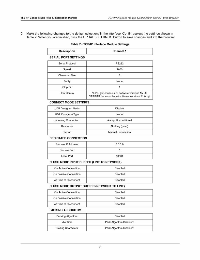
2. Make the following changes to the default selections in the interface. Confirm/select the settings shown in Table 7. When you are finished, click the UPDATE SETTINGS button to save changes and exit the browser.
Table 7.- TCP/IP Interface Module Settings
Description Channel 1
SERIAL PORT SETTINGS
Serial Protocol RS232
Speed 9600
Character Size 8
Parity None
Stop Bit 1
Flow Control NONE [for consoles w/ software versions 15-20] CTS/RTS [for consoles w/ software versions 21 & up]
CONNECT MODE SETTINGS
UDP Datagram Mode Disable
UDP Datagram Type None
Incoming Connection Accept Unconditional
Response Nothing (quiet)
Startup Manual Connection
DEDICATED CONNECTION
Remote IP Address 0.0.0.0
Remote Port 0
Local Port 10001
FLUSH MODE INPUT BUFFER (LINE TO NETWORK)
On Active Connection Disabled
On Passive Connection Disabled
At Time of Disconnect Disabled
FLUSH MODE OUTPUT BUFFER (NETWORK TO LINE)
On Active Connection Disabled
On Passive Connection Disabled
At Time of Disconnect Disabled
PACKING ALGORITHM
Packing Algorithm Disabled
Idle Time Pack Algorithm Disabled!
Trailing Characters Pack Algorithm Disabled!

TLS RF Console Site Prep & Installation Manual TCP/IP Interface Module Configuration Using A Web Browser
22
Send Immediate After Send Char
Disable
Send Char Define 2-Byte Sequence
Disable
Send Characters 01 Not Set
Send Characters 02 Not Set
ADDITIONAL SETTINGS
Disconnect Mode with DTR Drop
Check For Ctrl-D To Discon-nect
Disable
Port Password Disabled
Telnet Mode Disabled
Inactivity Timeout Enabled
Inactivity Timer 1:30
Port Password
Table 7.- TCP/IP Interface Module Settings
Description Channel 1


Australia21 Highgate StreetAuburn 2144NSW AustraliaTel: +61 2 8737 7777Email: [email protected]
BrazilRua ado Benatti, 92Sao Paulo - SP 05037-904Tel: +55 (0) 11 3611 2155Fax: +55 (0) 11 3611 1982Email: [email protected]
CanadaEastern CanadaTel: (519) 925-9899Western CanadaTel: (604) 576-4469Email: [email protected]
ChinaRoom 2202, Scitech TowerNo. 22 Jian Guomen Wai DaJieBeijing 100004Tel: +86 10 6512 8081Fax: +86 10 6522 0887Email: lu [email protected]
EnglandHydrex House, Garden RoadRichmond, Surrey TW9 4NRTel: +44 (0) 20 8392 1355Fax: +44 (0) 20 8878 6642Email: [email protected]
France94, rue Blaise Pascal, ZI des Mardelles93600 Aulnay-Sous-BoisTel: +33 (0) 1 48 79 55 90Fax: +33 (0) 1 48 68 39 00Email: [email protected]
GermanyFerdinand-Henze-Straße 9, D-33154 SalzkottenTel: +49 (0)52 58 130 Fax: +49 (0)52 58 131 07Email: [email protected]
ItalyVia de’Cattani, 220/G, 50145 Firenze Tel: +39 (0)55 30941 Fax: +39 (0)55 318603Email: [email protected]
MexicoSagitario #4529-3Col. La Calma C.P. 45070Zapopan, JaliscoTel: (523) 632 3482Fax: (523) 133 3219Email: [email protected]
Poland01-517 Warszawa ul. Mickiewicza 18/12Tel/Fax: +48 (0)22 839 0847Email: [email protected]
Singapore246 MacPherson Road#08-01 Betime Building348578 Tel: +65 (0) 6745 9265Fax: +65 (0) 6745 1791Email: francis [email protected]
Headquarters125 Powder Forest DriveSimsbury, CT 06070-7684Tel: (860) 651-2700Fax: (860) 651-2719Email: [email protected]
www.veeder.com