tcp/ip network essentials
TRANSCRIPT

TCP/IP Network Essentials
Linux System Administration and IP Services

Layers Complex problems can be solved using the
common divide and conquer principle. In this case the internals of the Internet are divided into separate layers. • Makes it easier to understand • Developments in one layer need not require changes in
another layer • Easy formation (and quick testing of conformation to)
standards Two main models of layers are used:
• OSI (Open Systems Interconnection) • TCP/IP

OSI Model
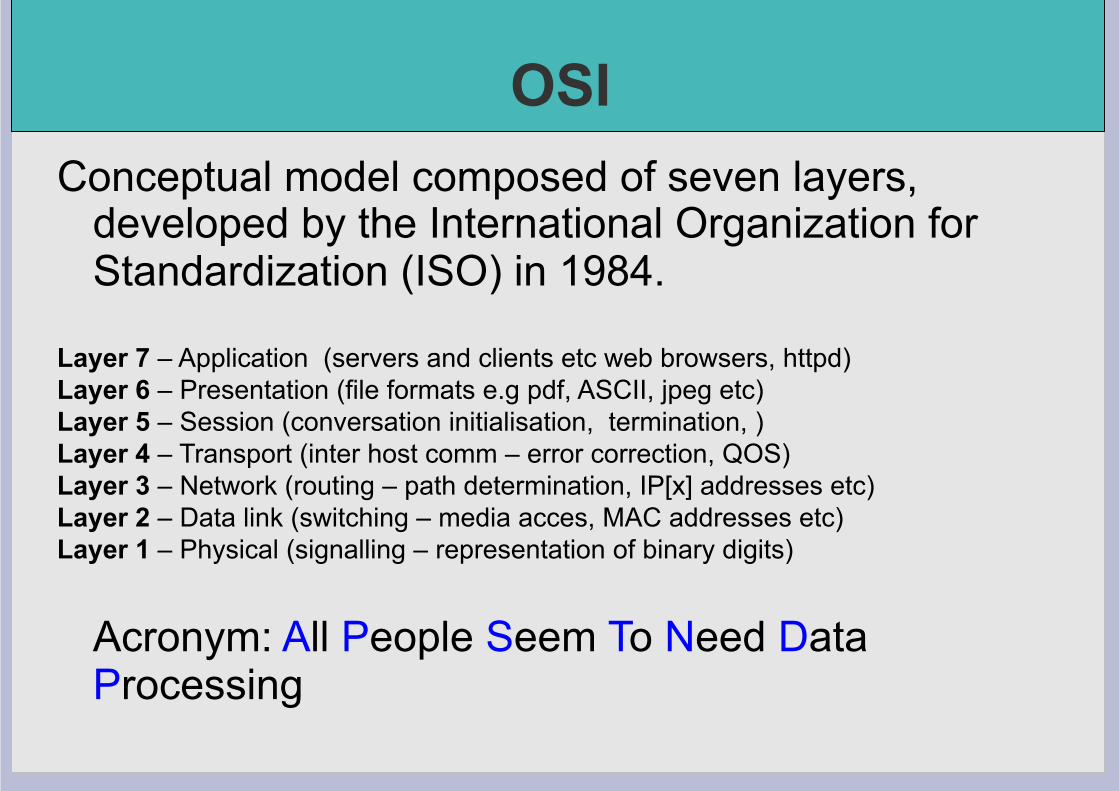
OSI Conceptual model composed of seven layers,
developed by the International Organization for Standardization (ISO) in 1984.
Layer 7 – Application (servers and clients etc web browsers, httpd) Layer 6 – Presentation (file formats e.g pdf, ASCII, jpeg etc) Layer 5 – Session (conversation initialisation, termination, ) Layer 4 – Transport (inter host comm – error correction, QOS) Layer 3 – Network (routing – path determination, IP[x] addresses etc) Layer 2 – Data link (switching – media acces, MAC addresses etc) Layer 1 – Physical (signalling – representation of binary digits)
Acronym: All People Seem To Need Data Processing

TCP/IP
Generally, TCP/IP (Transmission Control Protocol/Internet Protocol) is described using three to five functional layers. We have chosen the common DoD reference model, which is also known as the Internet reference model. • Process/Application Layer consists of applications and
processes that use the network. • Host-to-host transport layer provides end-to-end data delivery
services. • Internetwork layer defines the datagram and handles the
routing of data. • Network access layer consists of routines for accessing
physical networks.

TCP/IP model – the “hourglass”
Browser MUA
HTTP SMTP
TCP UDP
DNS RTSP
Video Player
ICMP
PING
IP
802.11 WiFi Ethernet PPP
Copper Fiber Pigeons Air :)

TCP/IP model – IPv4 and IPv6
Browser MUA
HTTP SMTP
TCP UDP
DNS RTSP
Video Player
ICMP
PING
802.11 WiFi Ethernet PPP
Copper Fiber Pigeons Air :)
IPv4 IPv6

OSI and TCP/IP
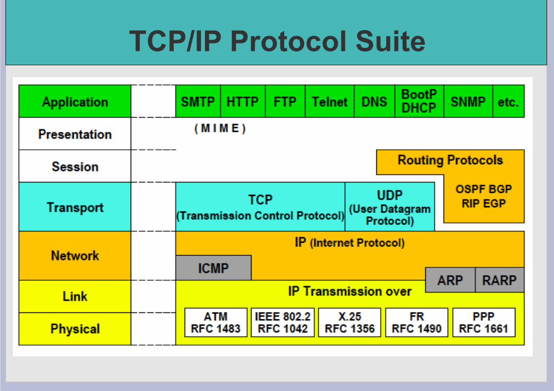
TCP/IP Protocol Suite

Encapsulation & Decapsulation
Lower layers add headers (and sometimes trailers) to upper layers packets
Application
Transport
Network
Data Link
Data
Data Header
Transport Packet Header Data Header Header
Network Packet Data Header Header
Header Header
Trailer Trailer

Frame, Datagram, Segment, Packet
Different names for packets at different layers • Ethernet (link layer) frame • IP (network layer) datagram • TCP (transport layer) segment
Terminology is not strictly followed • we often just use the term “packet” at any layer

Summary
Networking is a problem approached in layers. • OSI Layers • TCP/IP Layers
Each layer adds headers to the packet of the
previous layer as the data leaves the machine (encapsulation) and the reverse occurs on the receiving host (decapsulation)

So what is an IPv4 address anyway?
32 bit number (4 octet number) can be represented in lots of ways:
133 27 162 125
10000101 00011011 10100010 01111101
85 1B A2 7D

Calculating dec, hex, bin ipcalc is your friend - try: $ ipcalc 41.93.45.1 linux command line is your friend - try: $ echo 'ibase=10;obase=16;27' | bc 1B $ echo 'ibase=10;obase=2;27' | bc 11011 $ echo 'ibase=16;obase=A;1B' | bc 27

More to the structure
Hierarchical Division in IP Address: Network Part (Prefix) describes which network Host Part (Host Address) describes which host on that network
Boundary can be anywhere used to be a multiple of 8 (/8, /16/, /24), but not usual today
Network Host
205 . 154 . 8 1
11001101 10011010 00001000 00000001 Mask

Network Masks
Network Masks help define which bits are used to describe the Network Part and which for hosts
Different Representations: • decimal dot notation: 255.255.224.0 (128+64+32 in byte 3) • binary: 11111111 11111111 111 00000 00000000 • hexadecimal: 0xFFFFE000 • number of network bits: /19 (8 + 8 + 3)
Binary AND of 32 bit IP address with 32 bit netmask yields network part of address

Sample Netmasks
137.158.128.0/17 (netmask 255.255.128.0)
1000 1001 1001 1110 1 000 0000 0000 0000 1111 1111 1111 1111 1 000 0000 0000 0000
1100 0110 1000 0110 0000 0000 0000 0000 1111 1111 1111 1111 0000 0000 0000 0000
1100 1101 0010 0101 1100 0001 10 00 0000 1111 1111 1111 1111 1111 1111 11 00 0000
198.134.0.0/16 (netmask 255.255.0.0)
205.37.193.128/26 (netmask 255.255.255.192)

Allocating IP addresses
The subnet mask is used to define size of a network
E.g a subnet mask of 255.255.255.0 or /24 implies 32-24=8 host bits 2^8 minus 2 = 254 possible hosts
Similarly a subnet mask of 255.255.255.224 or /27 implies 32-27=5 host bits 2^5 minus 2 = 30 possible hosts

Special IP Addresses All 0’s in host part: Represents Network
e.g. 193.0.0.0/24 e.g. 138.37.128.0/17 e.g. 192.168.2.128/25 (WHY?)
All 1’s in host part: Broadcast (all hosts on net) e.g. 137.156.255.255 (137.156.0.0/16) e.g. 134.132.100.255 (134.132.100.0/24) e.g. 192.168.2.127/25 (192.168.2.0/25) (WHY?)
127.0.0.0/8: Loopback address (127.0.0.1) 0.0.0.0: Various special purposes (DHCP, etc.)

Networks – super- and subnetting
/24
/25
/27
....
By adding one bit to the netmask, we subdivide the network into two smaller networks. This is subnetting. i.e.: If one has a /26 network (32 – 26 = 6 => 2^6 => 64 addresses), that network can be subdivided into two subnets, using a /27 netmask, where the state of the last bit will determine which network we are addressing (32 – 27 = 5 => 2^5 => 32 addresses). This can be done recursively (/27 => 2 x /28 or 4 x /29, etc...). Example: 192.168.10.0/25 (.0 - .127) can be subnetted into 192.168.10.0 / 26 and 192.168.10.64 / 26
/27
/27
/27 /27
/27
/27
/27
/26
/26
/26
/26 /25

Networks – super- and subnetting
/24
/25
/25
Inversely, if two networks can be “joined” together under the same netmask, which encompasses both networks, then we are supernetting. Example: Networks 10.254.4.0/24 and 10.254.5.0/24 can be “joined” together into one network expressed: 10.254.4.0/23. Note: for this to be possible, the networks must be contiguous, i.e. it is not possible to supernet 10.254.5.0/24 and 10.254.6.0/24
/26
/26
/26
/26

Numbering Rules
Private IP address ranges (RFC 1918) • 10/8 (10.0.0.0 – 10.255.255.255) • 192.168/16 (192.168.0.0 – 192.168.255.255) • 172.16/12 (172.16.0.0 – 172.31.255.255)
• Public Address space available from AfriNIC • Choose a small block from whatever range you
have, and subnet your networks (to avoid problems with broadcasts, and implement segmentation policies – DMZ, internal, etc...)

Network related settings
Files
/etc/network/interfaces /etc/hosts /etc/resolv.conf
Commands
# ifconfig eth0 10.10.0.X/24 # route add default gw 10.10.0.254 # hostname pcX.ws.nsrc.org

Network related settings
Files /etc/network/interfaces – excerpt:
auto eth0 iface eth0 inet dhcp auto eth1 iface eth1 inet static address 41.93.45.101 gateway 41.93.45.1 netmask 255.255.255.0
/etc/resolv.conf - example: domain mydomain.org search mydomain.org nameserver 41.93.45.3

Network related settings
Commands Modern Linux distributions are in the process of deprecating ifconfig and route –
one new command does it all: #ip Try #ip addr show #ip route show #ip addr add 10.10.10.10 eth0 #ip route add default .... For details: #man ip

Routing
Every host on the internet needs a way to get packets to other hosts outside its local network.
This requires special hosts called routers that
can move packets between networks. Packets may pass through many routers
before they reach their destinations.

The route table All hosts (including routers) have a route table
that specifies which networks it is connected to, and how to forward packets to a gateway router that can talk to other networks.
Linux routing table from “netstat –rn46” Kernel IP routing table Destination Gateway Genmask Flags MSS Window irtt Iface 0.0.0.0 128.223.157.1 0.0.0.0 UG 0 0 0 eth0 128.223.157.0 0.0.0.0 255.255.255.128 U 0 0 0 eth0 Kernel IPv6 routing table Destination Next Hop Flag Met Ref Use If 2001:468:d01:103::/64 :: UAe 256 0 0 eth0 fe80::/64 :: U 256 0 0 eth0 ::/0 fe80::2d0:1ff:fe95:e000 UGDAe 1024 0 0 eth0 ::/0 :: !n -1 1 7 lo ::1/128 :: Un 0 1 1125 lo 2001:468:d01:103:3d8c:b867:f16d:efed/128 :: Un 0 1 0 lo 2001:468:d01:103:a800:ff:fe9c:4089/128 :: Un 0 1 0 lo fe80::a800:ff:fe9c:4089/128 :: Un 0 1 0 lo ff00::/8 :: U 256 0 0 eth0 ::/0 :: !n -1 1 7 lo

What do route table entries mean? Destination Gateway Genmask Flags MSS Window irtt Iface 0.0.0.0 128.223.157.1 0.0.0.0 UG 0 0 0 eth0 128.223.157.0 0.0.0.0 255.255.255.128* U 0 0 0 eth0 • The destination is a network address. • The gateway is an IP address of a router that can forward packets
(or 0.0.0.0, if the packet doesn't need to be forwarded). • Flags indicate various attributes for each route:
- U Up: The route is active. - H Host: The route destination is a single host. - G Gateway: Send anything for this destination on to this remote system, which will figure out from there where to send it. - D Dynamic: This route was dynamically created by something like gated or an ICMP redirect message. - M Modified: This route is set if the table entry was modified by an ICMP redirect message. - ! Reject: The route is a reject route and datagrams will be dropped.
• MSS is the Maximum Segment Size. Largest datagram kernel will construct for transmission via this route.
• Window is maximum data host will accept from a remote host. • irtt initial round trip time. • Iface the network inferface this route will use
*What size network is 255.255.255.128?

How the route table is used
A packet that needs to be sent has a destination IP address.
For each entry in the route table (starting with the
first): 1. Compute the logical AND of the destination IP and the genmask entry. 2. Compare that with the destination entry. 3. If those match, send the packet out the interface, and we're done. 4. If not, move on to the next entry in the table.

Reaching the local network
Suppose we want to send a packet to 128.223.143.42 using this route table.
Destination Gateway Genmask Flags Interface 128.223.142.0 0.0.0.0 255.255.254.0 U eth0 0.0.0.0 128.223.142.1 0.0.0.0 UG eth0 • In the first entry 128.223.143.42 AND 255.255.254.0 = 128.223.142.0 • This matches the destination of the first routing table entry, so
send the packet out interface eth0. • That first entry is called a network route.
Do you notice anything different about this routing table?

Reaching other networks
Suppose we want to send a packet to 72.14.213.99 using this route table.
Destination Gateway Genmask Flags Interface 128.223.142.0 0.0.0.0 255.255.254.0 U eth0 0.0.0.0 128.223.142.1 0.0.0.0 UG eth0 1. 72.14.213.99 AND 255.255.254.0 = 72.14.212.0 2. This does not match the first entry, so move on to the next
entry. 3. 72.14.213.99 AND 0.0.0.0 = 0.0.0.0 4. This does match the second entry, so forward the packet to
128.223.142.1 via bge0.

The default route
Note that this route table entry: Destination Gateway Genmask Flags Interface 0.0.0.0 128.223.142.1 0.0.0.0 UG eth0
matches every possible destination IP address.
This is called the default route. The gateway has to be a router capable of forwarding traffic.

More complex routing
Consider this route table: Destination Gateway Genmask Flags Interface 192.168.0.0 0.0.0.0 255.255.255.0 U eth0 192.168.1.0 0.0.0.0 255.255.255.0 U eth1 192.168.2.0 0.0.0.0 255.255.254.0 U eth2 192.168.4.0 0.0.0.0 255.255.252.0 U eth3 0.0.0.0 192.168.1.1 0.0.0.0 UG eth0
This is what a router's routing table might look
like. Note that there are multiple interfaces for multiple local networks, and a gateway that can reach other networks.

Forwarding packets
Any UNIX-like (and other) operating system can function as a gateway:
- In Ubuntu /etc/sysctl.conf set:
# Uncomment the next line to enable # packet forwarding for IPv4 #net/ipv4/ip_forward=1 # Uncomment the next line to enable # packet forwarding for IPv6 #net/ipv6/ip_forward=1

Forwarding packets
Important
Without forwarding enabled, the box will not forward packets from one interface to another: it is simply a host with multiple interfaces.