tdm firmware loader instructions dc & stepper motor … · note: tdm100/150 equipped with a dc...
TRANSCRIPT
TDM Firmware Loader Instructions DC & Stepper Motor Dispensers
07103-00231-03 May 22, 2014
Corporate Headquarters: 21405 B St.
Long Beach, MS 39560 Phone: (800) 259-6672 Fax: (228) 868-9445
Copyright Notice © 2014 Triton. All Rights Reserved. TRITON logo is a
registered trademark of Triton Systems of Delaware LLC.

DOCUMENT UPDATES
October 15, 2013 Original October 29, 2013 Rev B and added board/cable installation to TDM 100 December 12, 2013 Added synchronizing mainboard instructions May 22, 2014 Added Stepper Motor installation and Rev C
TDM 200 / 250
Tools Required T6 Driver
NO KIT REQUIRED
Description Quantity
Cassette Present Sensor w/ Security Switch 1
TDM 100 / 150 – DC Motor
Tools Required T6 Driver T20 Driver
TY Wrap Cutters
KIT P/N: 06200-00178
TDM 1xx Cassette Present w/Security Switch Board Upgrade Kit
PARTS SUPPLIED
Description Quantity
Cassette Present Sensor w/ Security Switch 1
Cassette Present Cable 1
T6 | 2.5mm x 6mm | Self-Tapping | Screw 1
6 inch TY Wraps 7
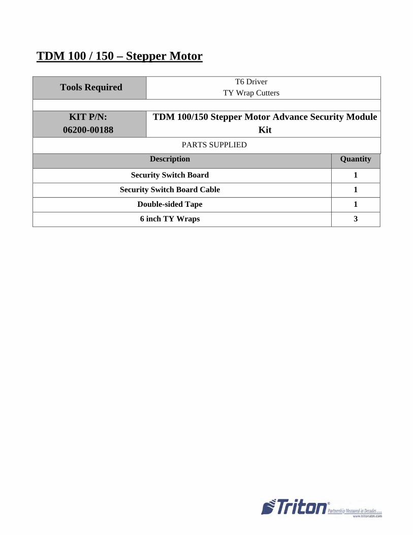
TDM 100 / 150 – Stepper Motor
Tools Required T6 Driver
TY Wrap Cutters
KIT P/N: 06200-00188
TDM 100/150 Stepper Motor Advance Security Module Kit
PARTS SUPPLIED
Description Quantity
Security Switch Board 1
Security Switch Board Cable 1
Double-sided Tape 1
6 inch TY Wraps 3
Page 1 of 31
Installing the TDM Cassette Present Sensor with Security Switch
Before starting installation of TDM Firmware Loader v16.03 Rev C, the TDM Cassette Sensor with
Security Switch must be installed.
Always perform a proper shut down of ATM before servicing the TDM mechanism.
TDM 200/250
Tools Needed: ‐ T6 Driver
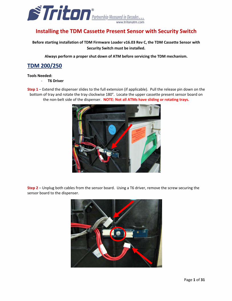
Step 1 – Extend the dispenser slides to the full extension (if applicable). Pull the release pin down on the bottom of tray and rotate the tray clockwise 180°. Locate the upper cassette present sensor board on
the non‐belt side of the dispenser. NOTE: Not all ATMs have sliding or rotating trays.
Step 2 – Unplug both cables from the sensor board. Using a T6 driver, remove the screw securing the sensor board to the dispenser.
Page 2 of 31
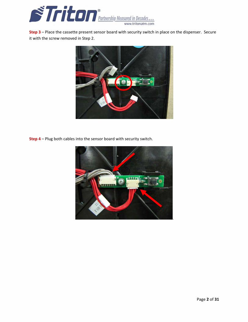
Step 3 – Place the cassette present sensor board with security switch in place on the dispenser. Secure
it with the screw removed in Step 2.
Step 4 – Plug both cables into the sensor board with security switch.
.

Page 3 of 31
TDM 100/150 – DC Motor
NOTE: TDM100/150 equipped with a DC motor, dispensers manufactured after
May 2, 2005 (Julian date: 12205), perform pages 4 – 12.
Older model TDM100s equipped with a Stepper Motor skip to page 13.
DC Motor
Page 4 of 31
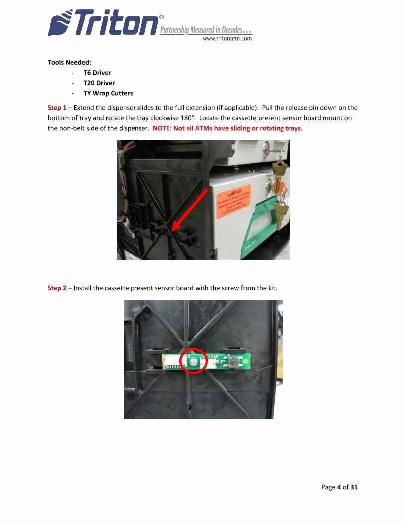
Tools Needed:
‐ T6 Driver
‐ T20 Driver
‐ TY Wrap Cutters
Step 1 – Extend the dispenser slides to the full extension (if applicable). Pull the release pin down on the
bottom of tray and rotate the tray clockwise 180°. Locate the cassette present sensor board mount on
the non‐belt side of the dispenser. NOTE: Not all ATMs have sliding or rotating trays.
Step 2 – Install the cassette present sensor board with the screw from the kit.
Page 5 of 31
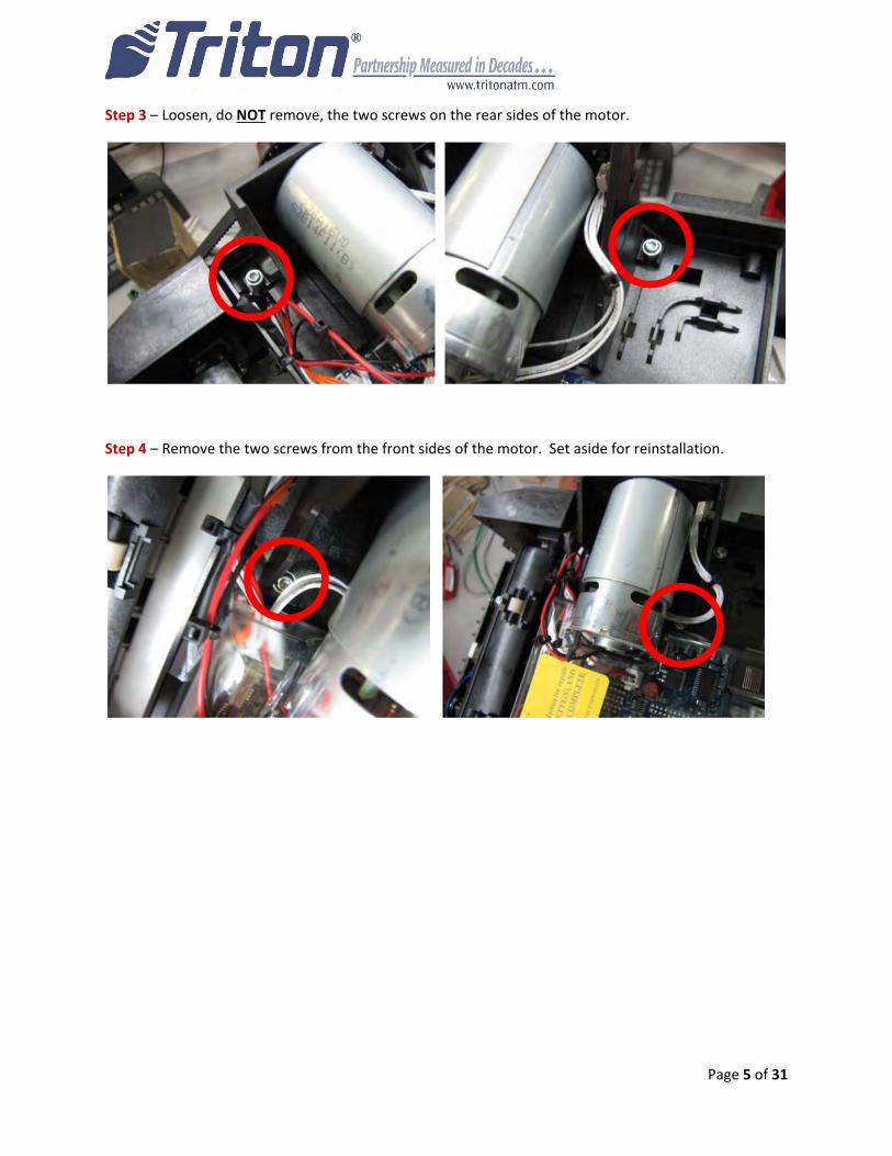
Step 3 – Loosen, do NOT remove, the two screws on the rear sides of the motor.
Step 4 – Remove the two screws from the front sides of the motor. Set aside for reinstallation.
Page 6 of 31
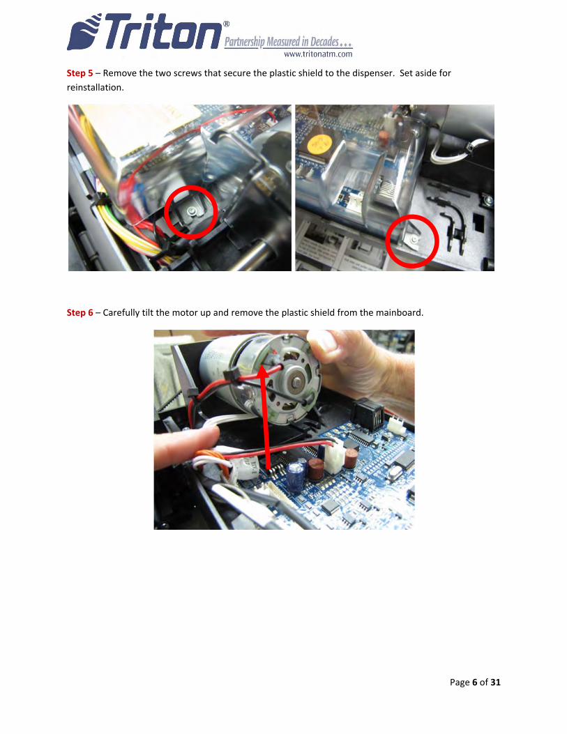
Step 5 – Remove the two screws that secure the plastic shield to the dispenser. Set aside for
reinstallation.
Step 6 – Carefully tilt the motor up and remove the plastic shield from the mainboard.
Page 7 of 31
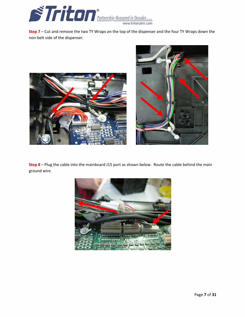
Step 7 – Cut and remove the two TY Wraps on the top of the dispenser and the four TY Wraps down the
non‐belt side of the dispenser.
Step 8 – Plug the cable into the mainboard J15 port as shown below. Route the cable behind the main
ground wire.
Page 8 of 31
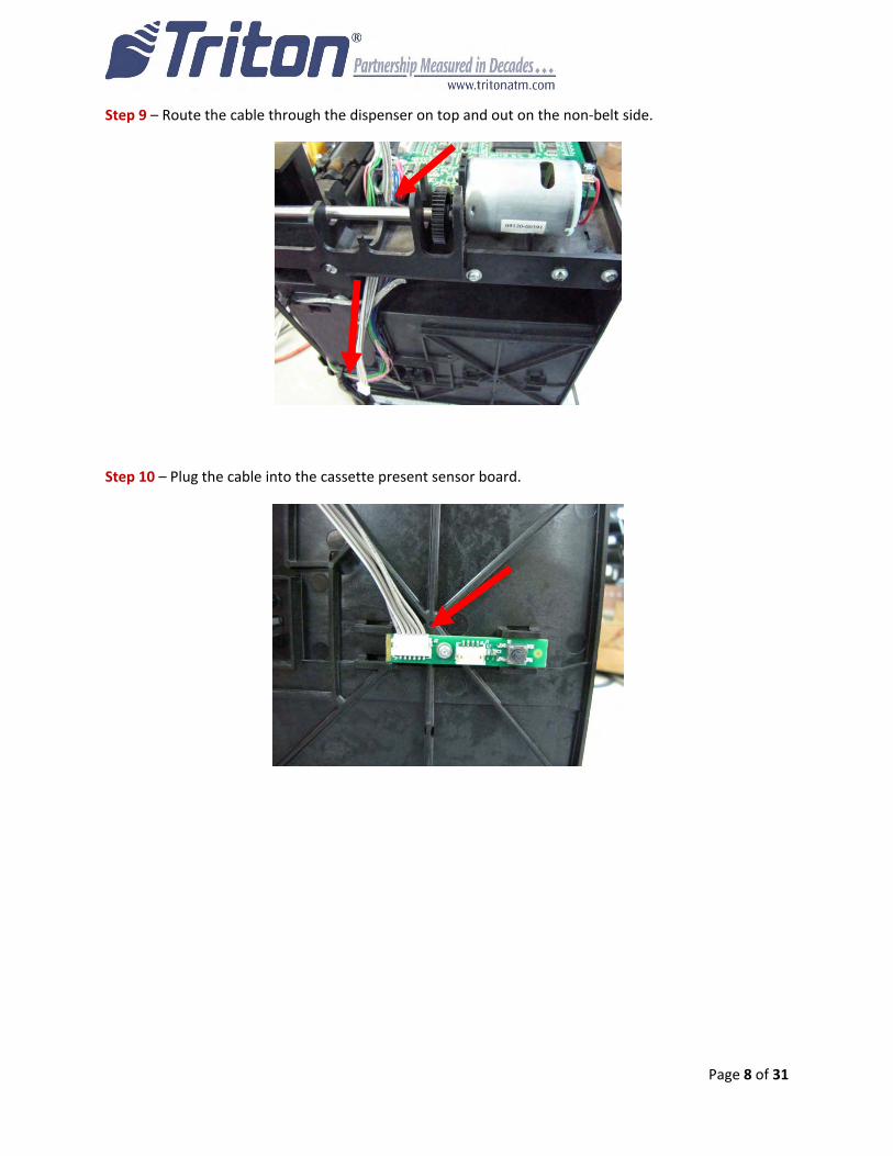
Step 9 – Route the cable through the dispenser on top and out on the non‐belt side.
Step 10 – Plug the cable into the cassette present sensor board.
Page 9 of 31
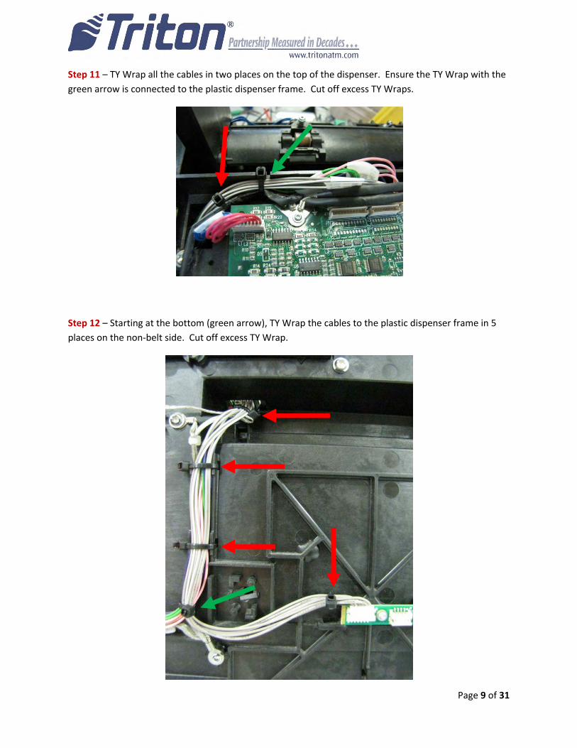
Step 11 – TY Wrap all the cables in two places on the top of the dispenser. Ensure the TY Wrap with the
green arrow is connected to the plastic dispenser frame. Cut off excess TY Wraps.
Step 12 – Starting at the bottom (green arrow), TY Wrap the cables to the plastic dispenser frame in 5
places on the non‐belt side. Cut off excess TY Wrap.
Page 10 of 31
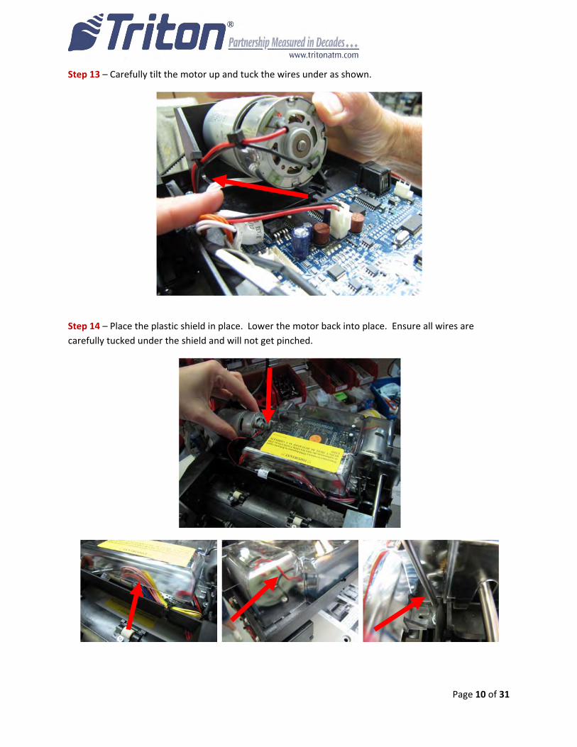
Step 13 – Carefully tilt the motor up and tuck the wires under as shown.
Step 14 – Place the plastic shield in place. Lower the motor back into place. Ensure all wires are
carefully tucked under the shield and will not get pinched.
Page 11 of 31
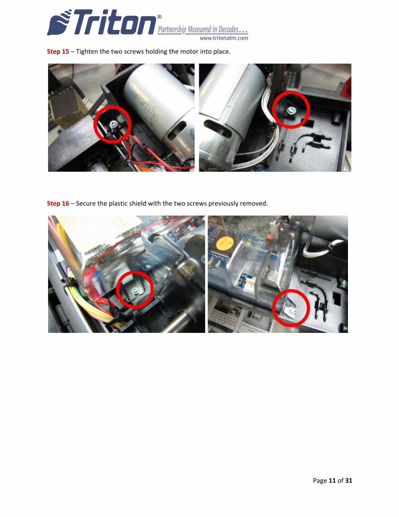
Step 15 – Tighten the two screws holding the motor into place.
Step 16 – Secure the plastic shield with the two screws previously removed.
Page 12 of 31
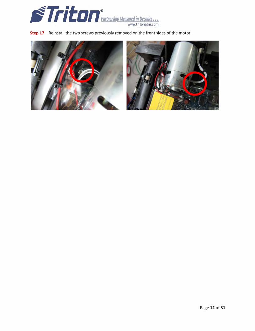
Step 17 – Reinstall the two screws previously removed on the front sides of the motor.
Page 13 of 31
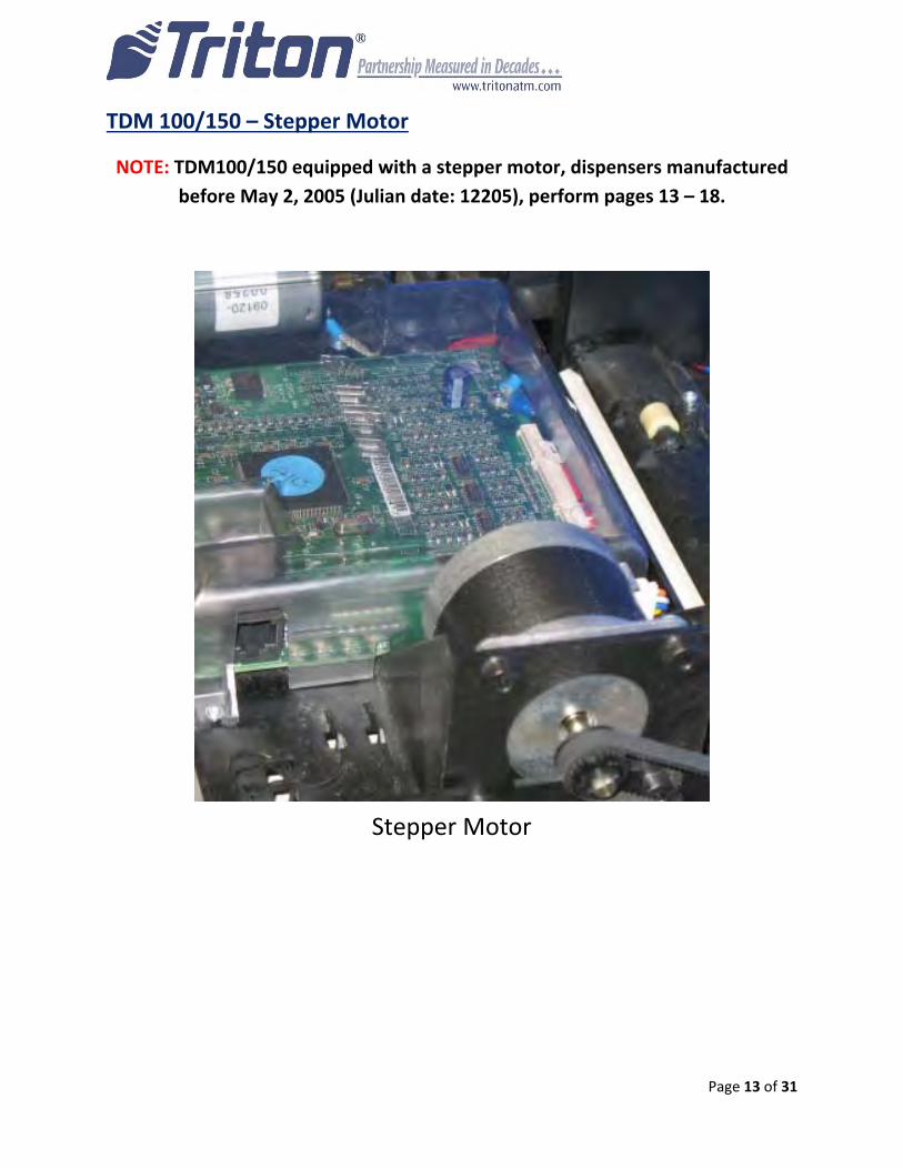
TDM 100/150 – Stepper Motor
NOTE: TDM100/150 equipped with a stepper motor, dispensers manufactured
before May 2, 2005 (Julian date: 12205), perform pages 13 – 18.
Stepper Motor
Page 14 of 31
Tools Needed:
‐ T6 Driver
‐ TY Wrap Cutters
Step 1 – Extend the dispenser slides to the full extension (if applicable). Pull the release pin down on the
bottom of tray and rotate the tray clockwise 180°. NOTE: Not all ATMs have sliding or rotating trays.
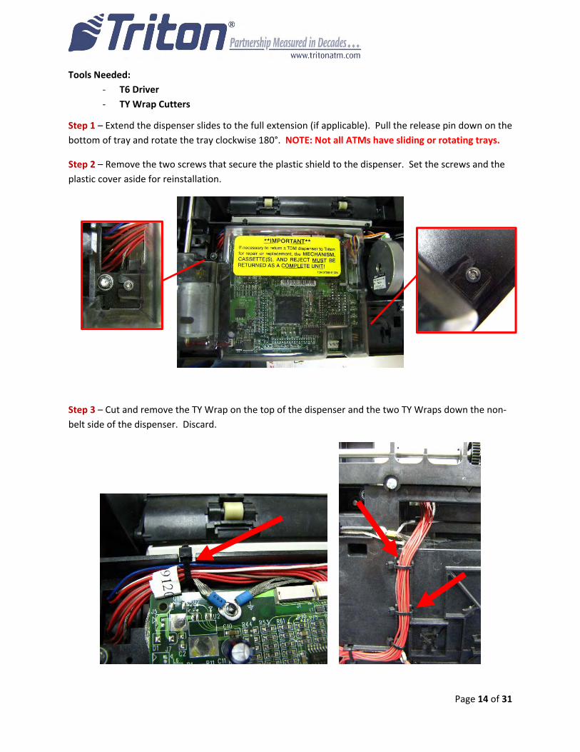
Step 2 – Remove the two screws that secure the plastic shield to the dispenser. Set the screws and the
plastic cover aside for reinstallation.
Step 3 – Cut and remove the TY Wrap on the top of the dispenser and the two TY Wraps down the non‐
belt side of the dispenser. Discard.
Page 15 of 31
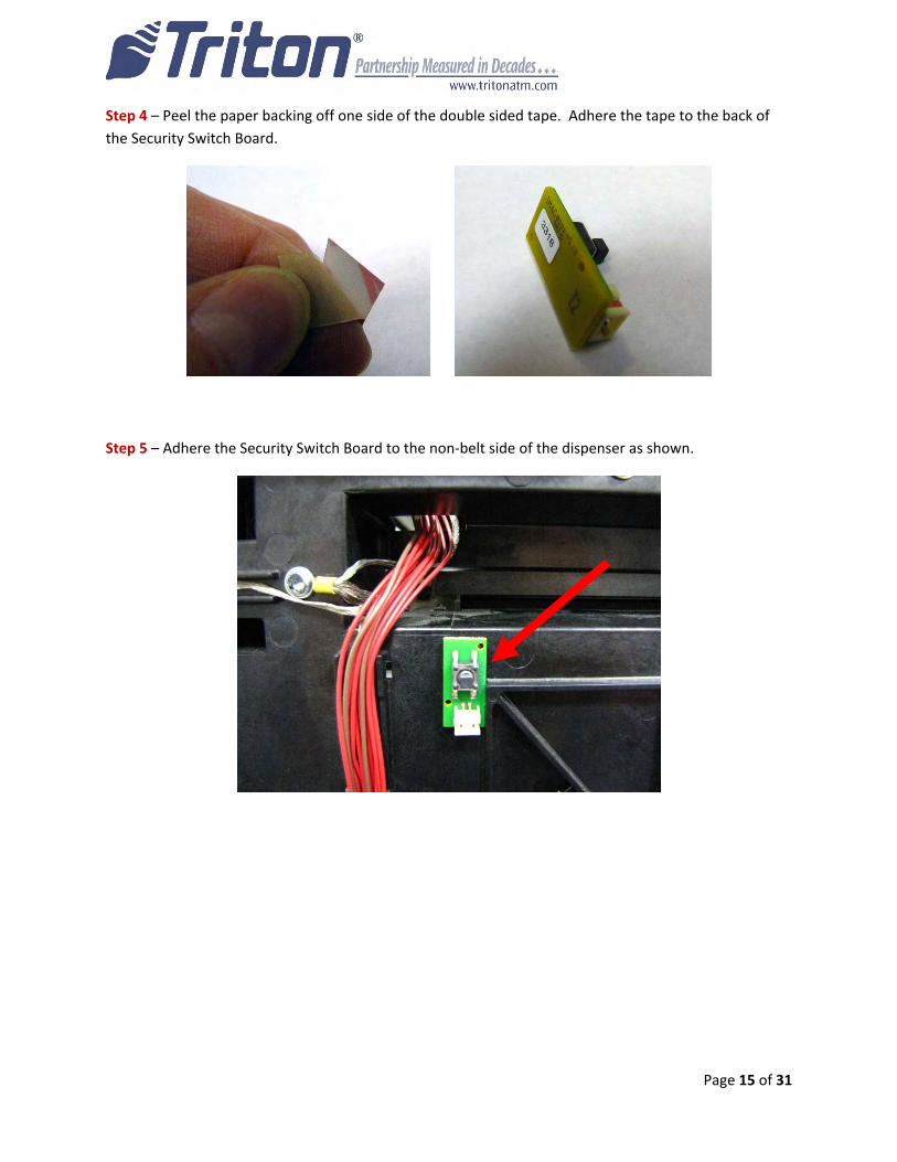
Step 4 – Peel the paper backing off one side of the double sided tape. Adhere the tape to the back of
the Security Switch Board.
Step 5 – Adhere the Security Switch Board to the non‐belt side of the dispenser as shown.
Page 16 of 31
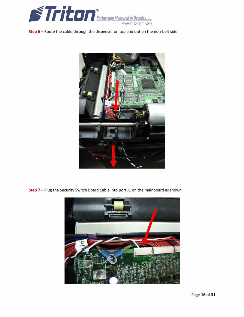
Step 6 – Route the cable through the dispenser on top and out on the non‐belt side.
Step 7 – Plug the Security Switch Board Cable into port J1 on the mainboard as shown.
Page 17 of 31
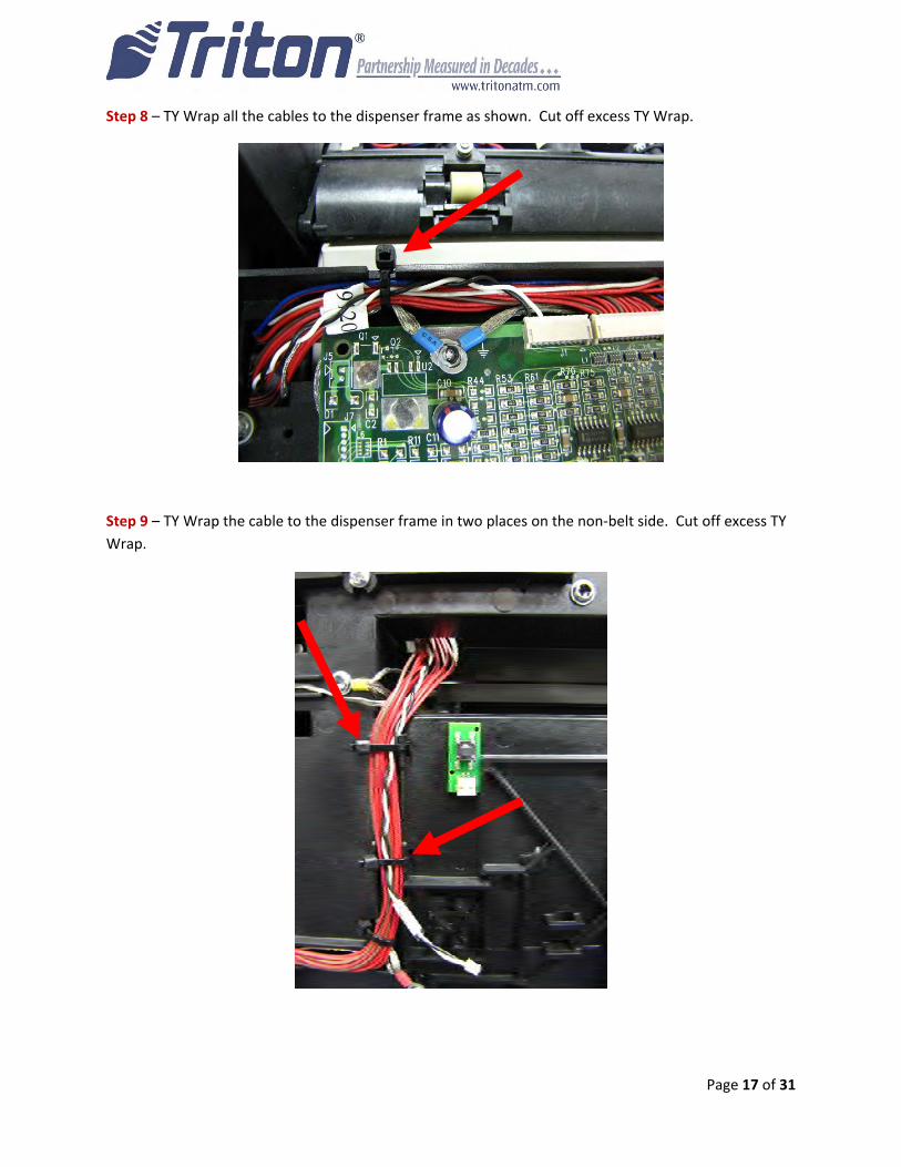
Step 8 – TY Wrap all the cables to the dispenser frame as shown. Cut off excess TY Wrap.
Step 9 – TY Wrap the cable to the dispenser frame in two places on the non‐belt side. Cut off excess TY
Wrap.
Page 18 of 31
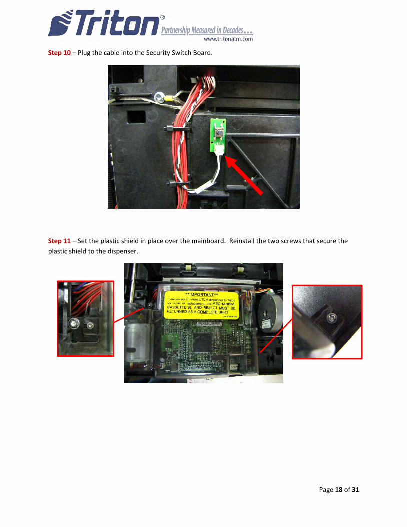
Step 10 – Plug the cable into the Security Switch Board.
Step 11 – Set the plastic shield in place over the mainboard. Reinstall the two screws that secure the
plastic shield to the dispenser.
Page 19 of 31
Installing the TDM Firmware Loader on a PC
Before starting installation of TDM Firmware Loader v16.03 Rev C, unplug the comloc from the PC and
the data cable from the dispenser.
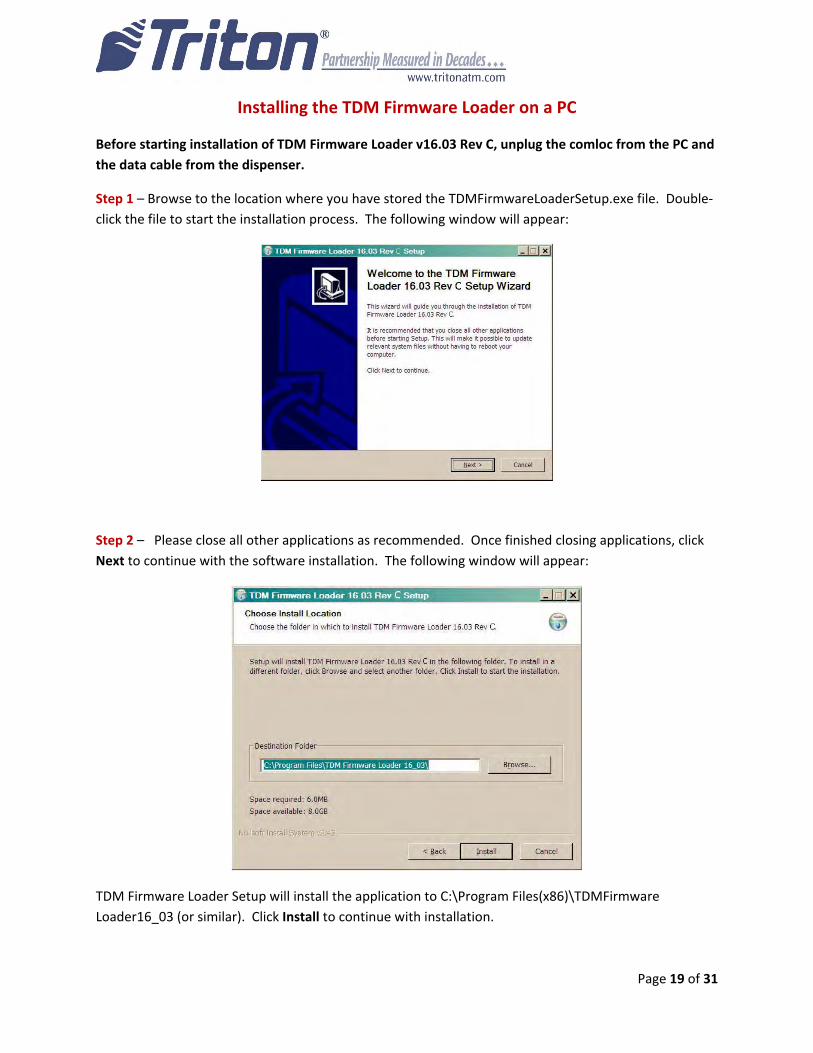
Step 1 – Browse to the location where you have stored the TDMFirmwareLoaderSetup.exe file. Double‐
click the file to start the installation process. The following window will appear:
Step 2 – Please close all other applications as recommended. Once finished closing applications, click
Next to continue with the software installation. The following window will appear:
TDM Firmware Loader Setup will install the application to C:\Program Files(x86)\TDMFirmware
Loader16_03 (or similar). Click Install to continue with installation.

Page 20 of 31
Step 3 – When prompted, remove the COMLOC (if installed) from the computer and click OK.
Step 4 – When prompted, attach the COMLOC to the computer and click OK.
Step 5 – When the installation is complete, the “Completing the TDM Firmware Loader 16.03 Rev C
Setup Wizard” box will appear.
To start the Firmware upgrade on the TDM, ensure the “Run TDM Firmware Loader 16.03 Rev C”
box is checked and click Finish.
To upgrade the Firmware on the TDM at a later time, uncheck the “Run TDM Firmware Loader
16.03 Rev C” box and click Finish.
Page 21 of 31
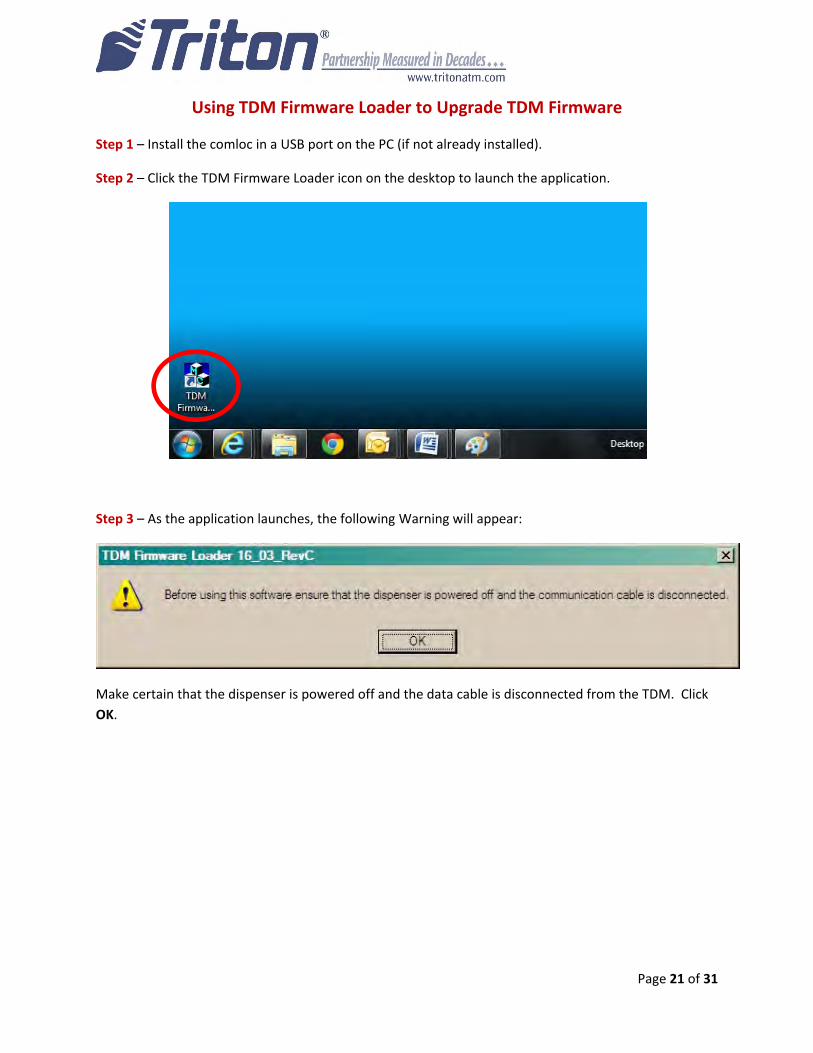
Using TDM Firmware Loader to Upgrade TDM Firmware
Step 1 – Install the comloc in a USB port on the PC (if not already installed).
Step 2 – Click the TDM Firmware Loader icon on the desktop to launch the application.
Step 3 – As the application launches, the following Warning will appear:
Make certain that the dispenser is powered off and the data cable is disconnected from the TDM. Click
OK.
Page 22 of 31
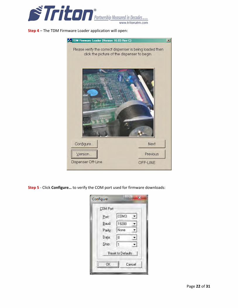
Step 4 – The TDM Firmware Loader application will open:
Step 5 ‐ Click Configure… to verify the COM port used for firmware downloads:
Page 23 of 31
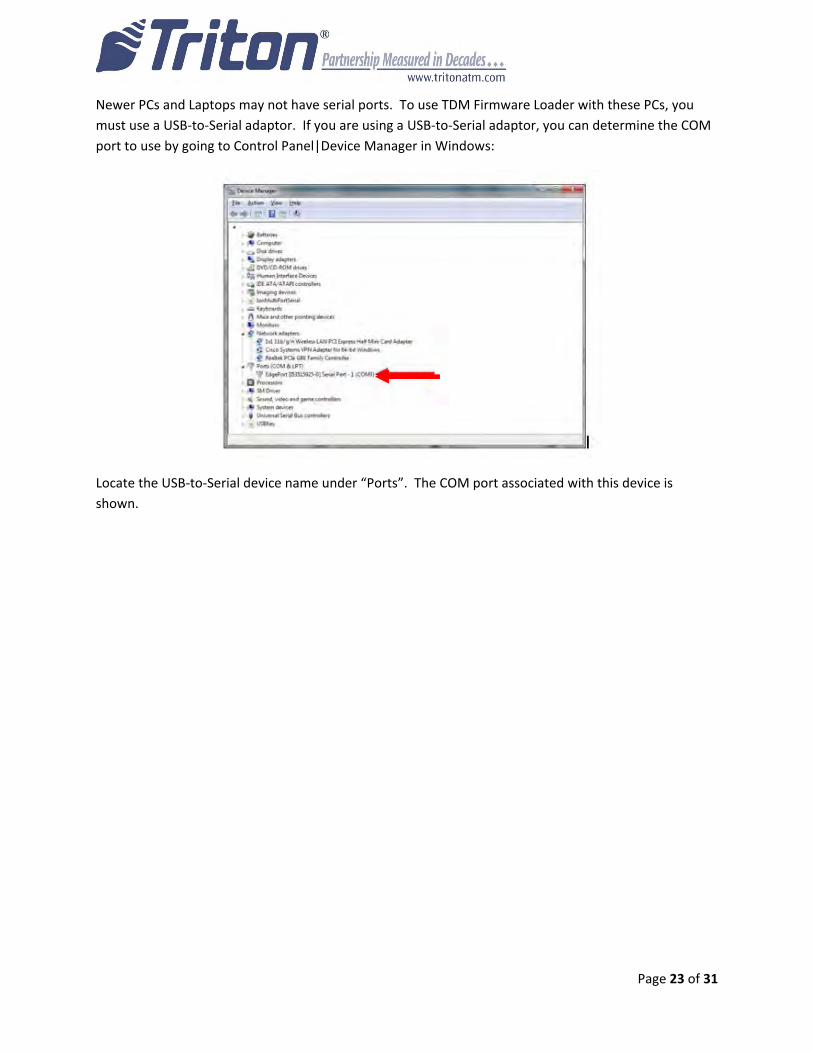
Newer PCs and Laptops may not have serial ports. To use TDM Firmware Loader with these PCs, you
must use a USB‐to‐Serial adaptor. If you are using a USB‐to‐Serial adaptor, you can determine the COM
port to use by going to Control Panel|Device Manager in Windows:
Locate the USB‐to‐Serial device name under “Ports”. The COM port associated with this device is
shown.

Page 24 of 31
Step 6 – Click “Next” or “Previous” to find the picture that matches your TDM:
IMPORTANT: If you select the wrong dispenser and the firmware load fails, the TDM Firmware Loader
application will need to be closed and reopened before attempting another download.
Once the correct picture is shown, click on the picture.

Page 25 of 31
Step 7 – Verify that your TDM matches the photo in the window that appears:
Click Yes if the picture matches your TDM dispenser. Click No to return to the previous window and
select another dispenser.
NOTE: This TDM Firmware Loader application does not support all TDM types. Verify that the dispenser
you wish to load matches the one pictured.
Step 8 – Once you click Yes, turn on the dispenser’s power:
Click OK once the dispenser is powered.

Page 26 of 31
Step 9 – Once you have powered the dispenser and clicked OK, connect the data cable to the load port
on the dispenser:
Click OK after connecting the data cable. The firmware download will start automatically.
Note the window now says “Dispenser Opened”.
The Firmware Download will take approximately 30 seconds – 2 minutes.
Page 27 of 31
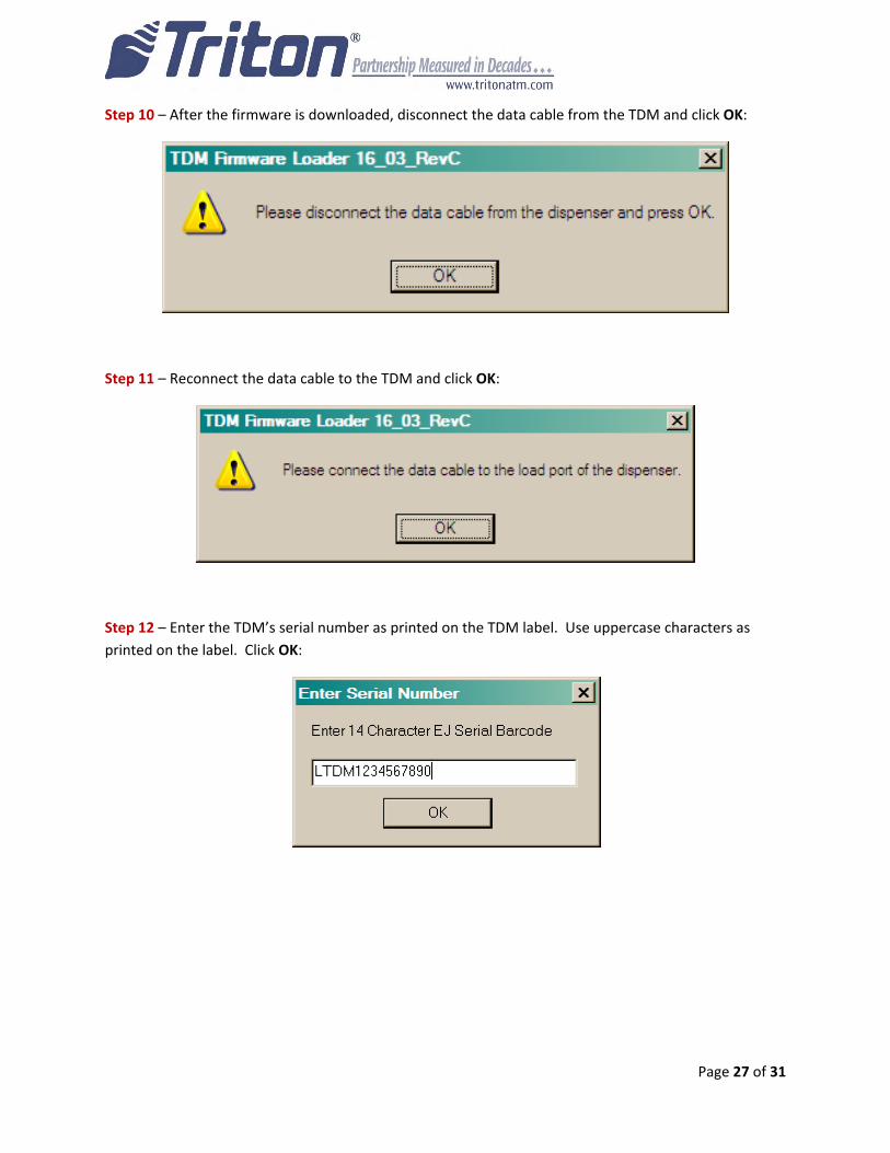
Step 10 – After the firmware is downloaded, disconnect the data cable from the TDM and click OK:
Step 11 – Reconnect the data cable to the TDM and click OK:
Step 12 – Enter the TDM’s serial number as printed on the TDM label. Use uppercase characters as
printed on the label. Click OK:
Page 28 of 31
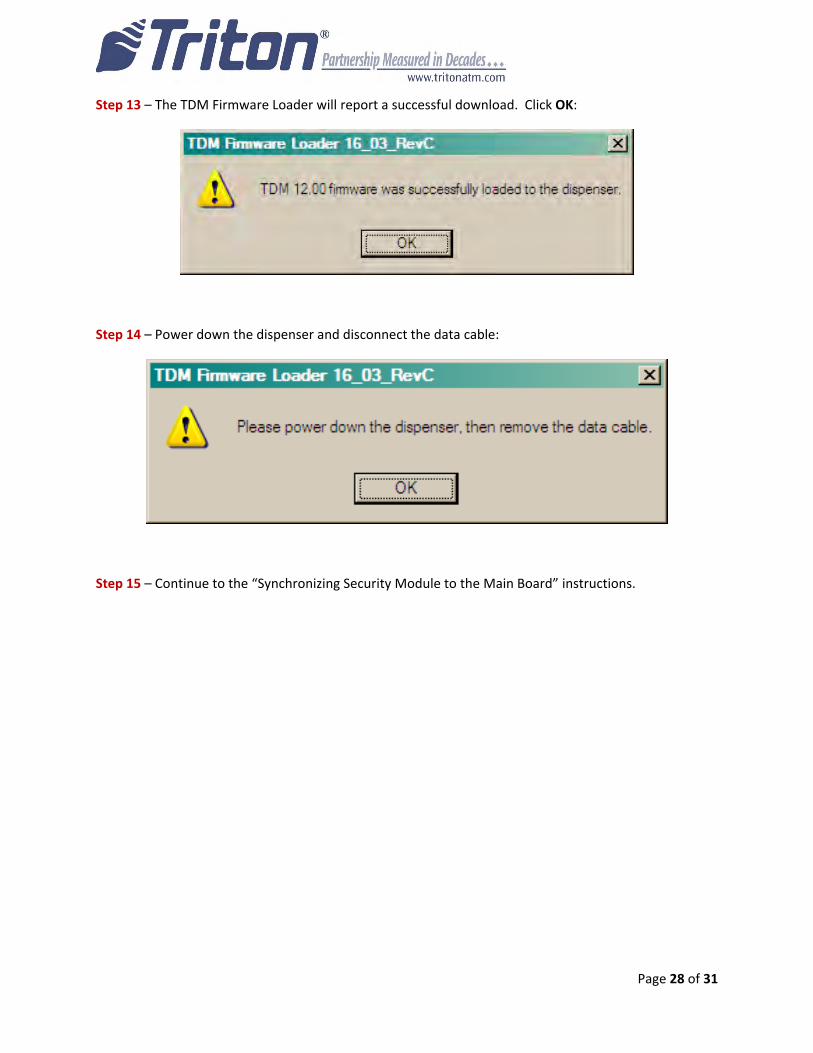
Step 13 – The TDM Firmware Loader will report a successful download. Click OK:
Step 14 – Power down the dispenser and disconnect the data cable:
Step 15 – Continue to the “Synchronizing Security Module to the Main Board” instructions.
Page 29 of 31
Synchronizing the Security Module to the Mainboard
Step 1‐ Power up the unit by flipping the power switch on the unit’s power supply to the “ON” position.
Step 2‐ When the unit is fully powered up, press and hold the “blank” key on the keypad and then press
the “1” key.
Step 3‐ Enter your password to log into Management Functions and press ENTER.
Step 4‐ If applicable, press “0” to navigate to the Main Menu page.
Step 5‐ On the Main Menu page, press “2” Diagnostics.
Step 6‐ On the Terminal Diagnostics page, press “4” Dispenser.
Step 7‐ On the Cash Dispenser Diagnostics page, press “7” Initialize Dispenser.
Step 8‐ Press ENTER on the keypad to confirm the initialization.
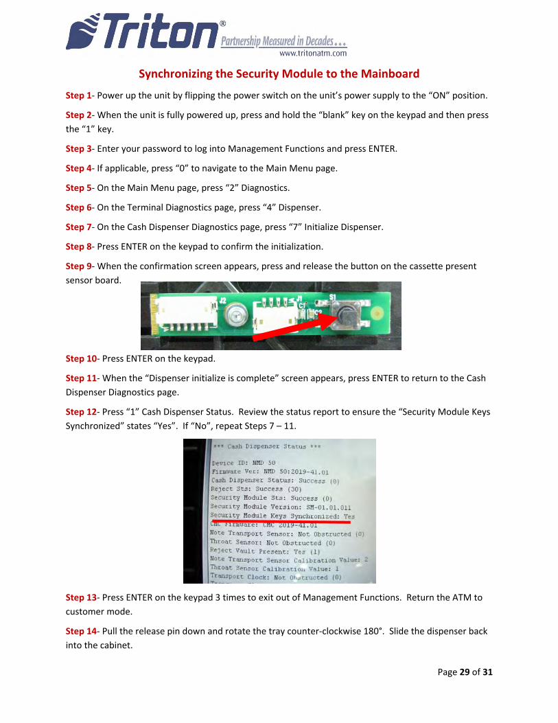
Step 9‐ When the confirmation screen appears, press and release the button on the cassette present
sensor board.
Step 10‐ Press ENTER on the keypad.
Step 11‐ When the “Dispenser initialize is complete” screen appears, press ENTER to return to the Cash
Dispenser Diagnostics page.
Step 12‐ Press “1” Cash Dispenser Status. Review the status report to ensure the “Security Module Keys
Synchronized” states “Yes”. If “No”, repeat Steps 7 – 11.
Step 13‐ Press ENTER on the keypad 3 times to exit out of Management Functions. Return the ATM to
customer mode.
Step 14‐ Pull the release pin down and rotate the tray counter‐clockwise 180°. Slide the dispenser back
into the cabinet.
Page 30 of 31
Updating Your TDM Firmware License
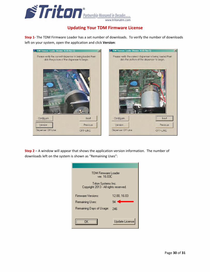
Step 1‐ The TDM Firmware Loader has a set number of downloads. To verify the number of downloads
left on your system, open the application and click Version:
Step 2 – A window will appear that shows the application version information. The number of
downloads left on the system is shown as “Remaining Uses”:
Page 31 of 31
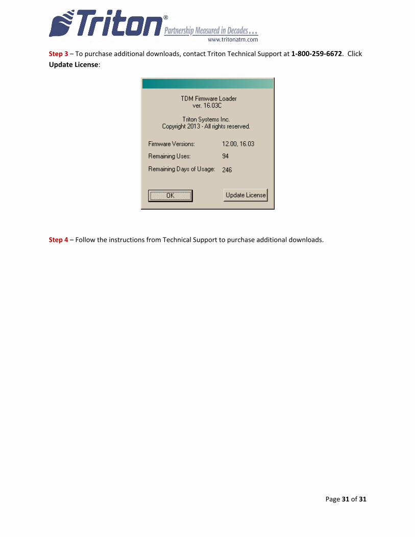
Step 3 – To purchase additional downloads, contact Triton Technical Support at 1‐800‐259‐6672. Click
Update License:
Step 4 – Follow the instructions from Technical Support to purchase additional downloads.