tdq06s24b-4 (en41qyba) dc-dc converter
TRANSCRIPT

TDQ06S24B-4 (EN41QYBA) DC-DC Converter
Technical Manual V1.1Issue V1.1
Date 2019-04-02
HUAWEI TECHNOLOGIES CO., LTD.

About This Document
PurposeThis document describes the TDQ06S24B-4 (EN41QYBA) DC-DC Converter , including its electricalspecifications, features, applications, and communication.
The figures provided in this document are for reference only.
Intended AudienceThis document is intended for:
l Sales personnell Technical support engineersl System engineersl Software engineersl Hardware engineers
Symbol ConventionsThe symbols that may be found in this document are defined as follows.
Symbol Description
Indicates an imminently hazardous situation which, if not avoided, willresult in death or serious injury.
Indicates a potentially hazardous situation which, if not avoided, couldresult in death or serious injury.
Indicates a potentially hazardous situation which, if not avoided, mayresult in minor or moderate injury.
Indicates a potentially hazardous situation which, if not avoided, couldresult in equipment damage, data loss, performance deterioration, orunanticipated results.NOTICE is used to address practices not related to personal injury.
Calls attention to important information, best practices and tips.NOTE is used to address information not related to personal injury,equipment damage, and environment deterioration.
TDQ06S24B-4 DC-DCConverter
Technical Manual V1.1 About This Document
i

Change HistoryChanges between document issues are cumulative. The latest document issue contains all the changes made inearlier issues.
Issue 1.1 (2019-04-02)Updated 7 Mechanical Overview.
Issue 1.0 (2019-03-26)This issue is the first release.
TDQ06S24B-4 DC-DCConverter
Technical Manual V1.1 About This Document
ii

Contents
About This Document...................................................................................................................... i
1 Product Overview..........................................................................................................................1
2 Electrical Specifications............................................................................................................... 22.1 Environmental................................................................................................................................................................ 22.2 Input................................................................................................................................................................................22.3 Output............................................................................................................................................................................. 32.4 Efficiency........................................................................................................................................................................42.5 Protection........................................................................................................................................................................42.6 Dynamic Characteristics.................................................................................................................................................52.7 Insulation Characteristics............................................................................................................................................... 52.8 Other Characteristics...................................................................................................................................................... 5
3 Remote On/Off...............................................................................................................................6
4 Output Voltage Trim.................................................................................................................... 7
5 Remote Sense................................................................................................................................. 8
6 Protection Characteristic.............................................................................................................. 9
7 Mechanical Overview................................................................................................................. 10
8 Safety..............................................................................................................................................118.1 EMC Specifications...................................................................................................................................................... 118.2 Recommended Fuse......................................................................................................................................................118.3 Recommended Reverse Polarity Protection Circuit..................................................................................................... 118.4 Qualification Testing.................................................................................................................................................... 128.5 Thermal Consideration................................................................................................................................................. 128.6 MSL Rating.................................................................................................................................................................. 138.7 Mechanical Consideration............................................................................................................................................ 13
TDQ06S24B-4 DC-DCConverter
Technical Manual V1.1 Contents
iii

1 Product Overview
Features
l Efficiency: ≥ 90% (TA = 25°C; Vin = 110 VDC)
l Length x Width x Height: 60.6 x 39 x 12.7mm (2.39 x 1.54 x 0.50 in.)
l Weight: 100 gl Input undervoltage protection, output
overvoltage protection (hiccup mode), outputovercurrent protection (hiccup mode), outputshort circuit protection (hiccup mode),andovertemperature protection (self-recovery)
l Remote on/offl UL,CE certificationl UL 60950-1, UL62368-1, EN 60950-1,
EN62368-1, IEC 61000-4-2, IEC 61000-4-5,IEC 61000-4-29 and EN55032 compliant
l RoHS6 and IPC9592B compliant
Product Description
The TDQ06S24B-4 is a new generation isolatedDC-DC converter that uses an industry non-standard quarter-brick structure, featuring highefficiency and power density with low outputripple and noise.It operates from an input voltagerange of 60 V to 160 V, and provides the ratedoutput voltage of 24 V as well as the themaximum output current of 6 A.
Model Naming Convention Applications
1 — 60-160V input, high performance, digtialcontrol, nonstandard2 — Output current: 6 A3 — Single output4 — Output voltage: 24 V5 — With a baseplate6 — Pin length: 4.8 mm
l Electric powerl Railway and metrol Automobilel Industrial equipment
TDQ06S24B-4 DC-DCConverter
Technical Manual V1.1 1 Product Overview
1

2 Electrical Specifications
2.1 Environmental
Table 2-1 Environmental specification
Parameter Min. Typ. Max. Unit Notes & Conditions
Operating ambient temperature(TA)
–40 - 85 °C Baseplate temperature, TB≤100℃,
see Figure 2-1
Storage temperature –45 - 125 °C -
Operating humidity 5 - 95 % RH Non-condensing
Altitude - - 5000 m -
Figure 2-1 Baseplate temperature measuring point
2.2 Input
Table 2-2 Input specification
Parameter Min. Typ. Max.
Unit Notes & Conditions
Input voltage 60 - 160 V -
Input transient voltage (1 s) - - 200 V -
TDQ06S24B-4 DC-DCConverter
Technical Manual V1.1 2 Electrical Specifications
2

Parameter Min. Typ. Max.
Unit Notes & Conditions
Maximum input current - - 6 A Vin = 0–160 V, Iout = 6 A
No-load loss - - 9.6 W Vin = 110 V, TA = 25℃
Input capacitance 100 - - µF Aluminum electrolytic capacitor
2.3 Output
Table 2-3 Output specification
Parameter Min. Typ. Max. Unit Notes & Conditions
Output voltage setpoint 23.76 24.00 24.24 V Vin = 110 V; Iout = 50%Ionom
TA = 25℃(Ionom = 6A)
Output current 0 - 6 A Vin = 60–160 V
Output power 0 - 144 W Vin = 60–160 V
Output line regulation –0.3 - 0.3 % Vin = 60–160 V; Iout = Ionom
Output load regulation –0.3 - 0.3 % Vin = 60–160 V; Iout = 0 - Ionom
Regulated voltage precision –3 - 3 % Vin = 60–160 V; Iout = 0 - Ionom
Temperature coefficient –0.02 - 0.02 %/°C TA = –40°C to +85°C(-40 ℉ to+185 ℉ )
External capacitance 470 - 2000 µF Aluminum solid capacitor.
Output voltage ripple and noise(peak to peak)
- - 400 mV Bandwidth: 20 MHz.
Output voltage Trim range 90 - 110 %
Output voltage overshoot - - 5 % Full range of Vin, Iout, and TA.
Output voltage delay time 0.3 - 5 s From Vin connection to 10% Vout.
Output voltage rise time - - 100 ms From 10% Vout to 90% Vout
Switching frequency 140 180 220 kHz Vin = 110 V; Iout = 50%Ionom; TA = 25℃
TDQ06S24B-4 DC-DCConverter
Technical Manual V1.1 2 Electrical Specifications
3

2.4 Efficiency
Table 2-4 Efficiency specification
Parameter Min. Typ. Max. Unit Notes & Conditions
100% load 90 - - % TA = 25°C, Vin = 110 V
2.5 Protection
Table 2-5 Input Protection
Parameter Min. Typ. Max. Unit Notes & Conditions
Input undervoltage protection startupthreshold
58 60 62 V -
Input undervoltage protectionshutdown threshold
56 58 60 V -
Input undervoltage protectionhysteresis
1 2 - V -
Table 2-6 Output Protection
Parameter Min. Typ. Max.
Unit Notes & Conditions
Output overcurrent protection 110 - 160 %Iomax Hiccup mode
Output short circuit protection - - - - Hiccup mode
Output overvoltage protection 28.1 - 30.5 V Hiccup mode
Overtemperature protection threshold 105 - 130 °C Self-recoveryThe values are obtained bymeasuring the temperature of thePCB near the thermal resistor.
Overtemperature protectionhysteresis
5 - - °C
TDQ06S24B-4 DC-DCConverter
Technical Manual V1.1 2 Electrical Specifications
4
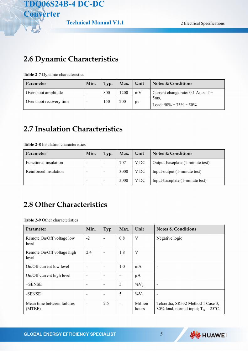
2.6 Dynamic Characteristics
Table 2-7 Dynamic characteristics
Parameter Min. Typ. Max. Unit Notes & Conditions
Overshoot amplitude - 800 1200 mV Current change rate: 0.1 A/µs, T =5ms,Load: 50%–75%–50%
Overshoot recovery time - 150 200 µs
2.7 Insulation Characteristics
Table 2-8 Insulation characteristics
Parameter Min. Typ. Max. Unit Notes & Conditions
Functional insulation - - 707 V DC Output-baseplate (1-minute test)
Reinforced insulation - - 3000 V DC Input-output (1-minute test)
- - 3000 V DC Input-baseplate (1-minute test)
2.8 Other Characteristics
Table 2-9 Other characteristics
Parameter Min. Typ. Max. Unit Notes & Conditions
Remote On/Off voltage lowlevel
-2 - 0.8 V Negative logic
Remote On/Off voltage highlevel
2.4 - 1.8 V
On/Off current low level - - 1.0 mA -
On/Off current high level - - - µA
+SENSE - - 5 %Vo -
-SENSE - - 5 %Vo -
Mean time between failures(MTBF)
- 2.5 - Millionhours
Telcordia, SR332 Method 1 Case 3;80% load, normal input; TA = 25°C.
TDQ06S24B-4 DC-DCConverter
Technical Manual V1.1 2 Electrical Specifications
5

3 Remote On/Off
The main output of module can be turned on or turned off by On/Off signal.
Logic Enable On/Off Pin Level Status
Negative logic Low level On
High level Off
Figure 3-1 Various circuits for driving the On/Off pin
TDQ06S24B-4 DC-DCConverter
Technical Manual V1.1 3 Remote On/Off
6

4 Output Voltage Trim
The output voltage can be adjusted according to the trim range specification by using the Trim pin.
Figure 4-1 Configuration diagram for Trim up
The relationship between Radj-up and Vout:
Figure 4-2 Configuration diagram for Trim down
The relationship between Radj-down and Vout:
TDQ06S24B-4 DC-DCConverter
Technical Manual V1.1 4 Output Voltage Trim
7

5 Remote Sense
This function is used to compensate for voltage drops on Rw. The Sense(+), Sense(-), Vout(+), and Vout(-)terminals should meet the following requirements:
[Vout(+) – Vout(-)] – [Sense(+) – Sense(-)] ≤ 10% x Vnom
(Vnom is the rated output voltage.)
Figure 5-1 Configuration diagram for remote sense
NOTE
1. Rw indicates the line impedance between the output terminal and the load.
2. If the remote sense function is disabled, the Sense(+) terminal directly connects to the Vout(+) terminal and the Sense(-)terminal directly connects to the Vout(-) terminal.
TDQ06S24B-4 DC-DCConverter
Technical Manual V1.1 5 Remote Sense
8

6 Protection Characteristic
l Input Undervoltage ProtectionThe converter will shut down after the input voltage drops below the undervoltage protection threshold forshutdown. The converter will start to work again after the input voltage reaches the input undervoltageprotection threshold for startup. For the hysteresis, see Table 2-5.
l Output Overvoltage ProtectionThe converter equipped with current limiting circuitry can provide protection from an output overload orshort circuit condition. If the output current exceeds the output overcurrent protection threshold, theconverter enters hiccup mode. When the fault condition is removed, the converter will automatically restart,see Table 2-6.
l Output Overcurrent ProtectionWhen the voltage directly across the output pins exceeds the output overvoltage protection threshold, theconverter will enter hiccup mode. When the fault condition is removed, the converter will automaticallyrestart.
l Overtemperature ProtectionA temperature sensor on the converter senses the average temperature of the module. It protects the converterfrom being damaged at high temperatures. When the temperature exceeds the overtemperature protectionthreshold, the output will shut down. It will allow the converter to turn on again when the temperature of thesensed location falls by the value of Overtemperature Protection Hysteresis.
TDQ06S24B-4 DC-DCConverter
Technical Manual V1.1 6 Protection Characteristic
9

7 Mechanical Overview
Figure 7-1 Mechanical overview
Table 7-1 Pin description
Pin No. Function Pin No. Function Pin No. Function
1 Vin (+) 4 Vout (-) 7 Sense(+)
2 ON/OFF 5 Sense (-) 8 Vout (+)
3 Vin (–) 6 Trim - -
NOTE
1. All dimensions in mm [in.].
Tolerances: x.x±0.5 mm [x.xx±0.02 in.]; x.xx±0.25 mm [x.xxx ± 0.010 in.].
2. Pin 1-3, 5-7 are 1.00 ± 0.05 mm [0.040 ± 0.002 in.] diameter with 2.00 ± 0.10 mm [0.080 ± 0.004 in.] diameter standoffshoulders. Pin 4 and pin 8 are 1.50 ± 0.05 mm [0.060 ± 0.002 in.] diameter with 2.50 ± 0.10 mm [0.098 ± 0.004 in.]diameter standoff shoulders.
3. M3 Screw used to boltt units base plate to other surfaces (such as heatsink) must not exceed 2.5 mm (0.10 in.) depth belowthe surface of base plate.
4. Components will vary between models.
TDQ06S24B-4 DC-DCConverter
Technical Manual V1.1 7 Mechanical Overview
10

8 Safety
8.1 EMC SpecificationsThe acceptance standard is required as the conducted emission limits of CISPR22 Class A with 6 dB margin.
Table 8-1 EMC
Items Standard Port Specification
CE EN55032 DC Input Class B, 6dB margin.
ESD IEC 61000-4-2 HCP/VCP Contact discharge +/-6KV, +/-8KV Criterion B;air discharge: +/-8KV, +/-15KV Criterion B;Input, Output
Baseplate
SURGE IEC 61000-4-5 DC Input DM:2kV/2Ω ,CM:4kV/12Ω, Criterion BDM /CM:1.8kV (5/50us), Criterion B
DC DIP IEC 61000-4-29 DC Input UT =110V Rated load, normal temperature test;0%UT, 100ms Criterion B40%UT, 100ms Criterion B70%UT, 100ms Criterion B
8.2 Recommended FuseThe converter has no internal fuse. To meet safety and regulatory requirements, a 6 A fuse is recommended.
8.3 Recommended Reverse Polarity Protection CircuitReverse polarity protection is recommended under installation and cabling conditions where reverse polarityacross the input may occur.
Figure 8-1 Recommended reverse polarity protection circuits
TDQ06S24B-4 DC-DCConverter
Technical Manual V1.1 8 Safety
11

8.4 Qualification TestingParameter Units Condition
Highly accelerated lifetest (HALT)
3 Low temperature limit: -60°C; high temperature limit: 110°C; vibrationlimit: 40 G; temp change rate: 40 ℃/min; vibration freq range: 10 Hz to10000 Hz; axes of vibration: X/Y/Z
Thermal shock 32 Temperature slope: 20°C/min; 700 cycles; Lasting for 30 minutes both at-40°C and +125°C
Thermal humidity bias(THB)
32 Maximum input voltage; 85°C; 85% RH; 1000 operating hours underlowest load power
High temperatureoperation bias (HTOB)
32 Rated input voltage; air flow: 0.5 m/s (100 LFM) to 5 m/s (1000 LFM);ambient temperature between +45°C and +55°C; 1000 operating hours;50% to 80% load
Power and temperaturecycling test (PTC)
32 Rated input voltage; air flow: 0.5 m/s (100 LFM) to 5 m/s (1000 LFM);ambient temperature between -40°C and +85°C; 1200 cycles; 50% load
8.5 Thermal Consideration
Thermal Test Point
Decide proper airflow to be provided by measuring the temperature of the PCB near the thermal resistor shown inFigure 23 to protect the converter against overtemperature. The overtemperature protection threshold is alsoobtained based on this thermal test point.
Figure 8-2 Thermal test point
Power Dissipation
The converter power dissipation is calculated based on efficiency. The following formula reflects the relationshipbetween the consumed power (Pd), efficiency (ŋ), and output power (Po): Pd = Po(1-ŋ)/ŋ.
TDQ06S24B-4 DC-DCConverter
Technical Manual V1.1 8 Safety
12

8.6 MSL RatingStore and transport the converter as required by the MSL rating 1 specified in the J-STD-020D/033C. The surfaceof a soldered converter must be clean and dry. Otherwise the assembly, test, or even reliability of the converterswill be negatively affected.
8.7 Mechanical Consideration
InstallationAlthough the converter can be mounted in any direction, free airflow must be available.
SolderingThe converter supports standard wave soldering and hand soldering. Reflow soldering is not allowed.
1. For wave soldering, the converter pins can be soldered at 260°C for less than 7 seconds.2. For reflow soldering, the converter pins can be soldered at 250°C for less than 10 seconds.3. For hand soldering, the iron temperature should be maintained at 350°C to 420°C and applied to the
converter pins for less than 10 seconds.
The converter can be rinsed using the isopropyl alcohol (IPA) solvent or other suitable solvents.
Figure 8-3 Recommended reflow profile using lead-free solder
TDQ06S24B-4 DC-DCConverter
Technical Manual V1.1 8 Safety
13

Copyright © Huawei Technologies Co., Ltd. 2019. All rights reserved.
No part of this document may be reproduced or transmitted in any form or by any means without prior written consent of Huawei Technologies Co., Ltd.
Trademarks and Permissions
and other Huawei trademarks are trademarks of Huawei Technologies Co., Ltd.
All other trademarks and trade names mentioned in this document are the property of their respective holders.
Notice
The purchased products, services and features are stipulated by the contract made between Huawei
and the customer. All or part of the products, services and features described in this document may not
be within the purchase scope or the usage scope. Unless otherwise specified in the contract, all
statements, information, and recommendations in this document are provided "AS IS" without
warranties, guarantees or representations of any kind, either express or implied.
The information in this document is subject to change without notice. Every effort has been made in the
preparation of this document to ensure accuracy of the contents, but all statements, information, and
recommendations in this document do not constitute a warranty of any kind, express or implied.
Huawei Technologies Co., Ltd.
Huawei Industrial BaseBantian, LonggangShenzhen 518129
People's Republic of China
www.huawei.com