teacher’s notes sustainable future: through …resources/~/media/documents...teacher’s notes...
TRANSCRIPT
© Queensland Museum 2010
Teacher’s notes Sustainable Future: through mechatronics
Overview: 1. Intelligent machines and how they can respond to the environment.
2. Introduction to programming intelligent machines.
a. Programming procedures: examples that give instructions to an intelligent machine
b. A sample test program: Motion test
c. Components of an intelligent machine: inputs, processor, outputs, energy sources.
d. 5 steps to programming using PicLogicator™ software.
3. Challenge activities for students solve: a guide for students
a. Let’s dance: Program to dance in time with selected music using the sound sensor to trigger changes in movement
b. The Heat Is On: Provide a warning alarm for a controlled temperature environment such as an egg incubator
c. Dodgem Cars: Design and construct a vehicle that can navigate around randomly placed obstacles. This vehicle is the forerunner for the first “crash proof” vehicle.
d. A Light on Activity: A security light needs to switch on automatically at dusk each day and turn off automatically at dawn each day.
4. Extended project ideas are suggested at the end of each of the four challenges above.
Note to user: Whilst this guide is based on the Picaxe 18X microprocessor chip and the PicLogicator™ software, the ideas contained in this guide can be applied to any platform that provides a programmable way of sensing and controlling the environment.
The key idea is that intelligent machines respond to the environment by sensing conditions then making decisions based on that data. The guide presented here provides a framework for student learning to occur.
2
© Queensland Museum 2007
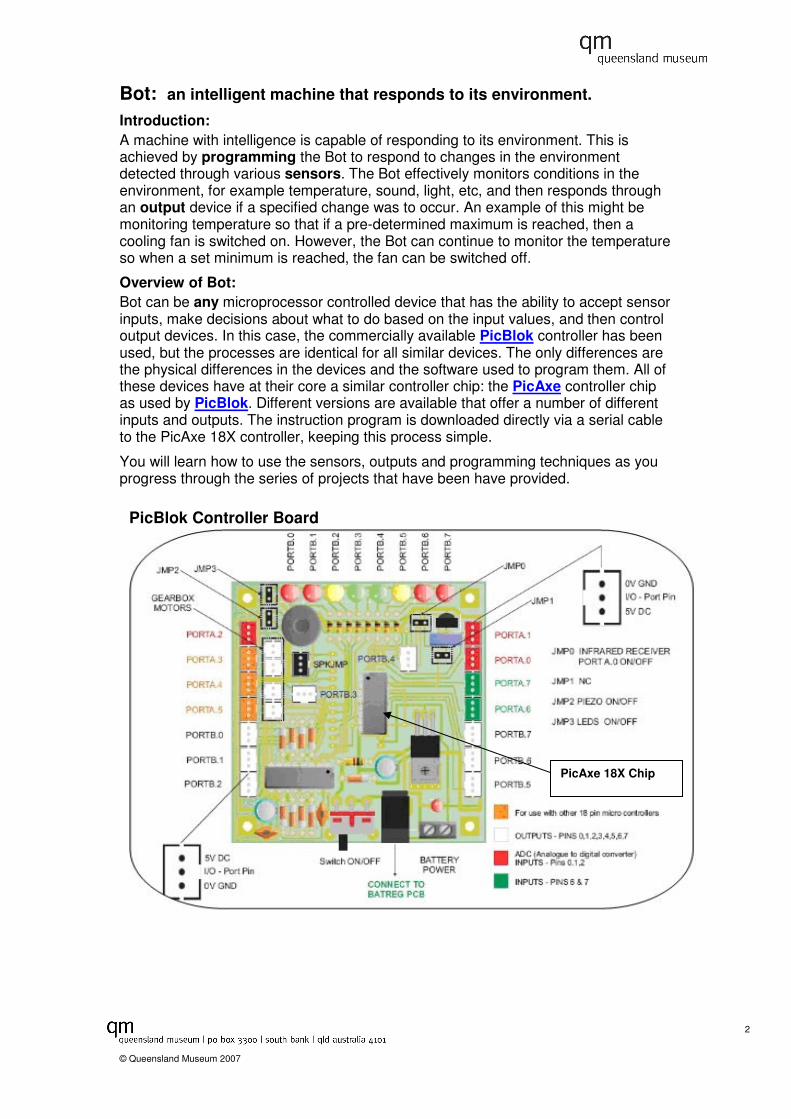
PicBlok Controller Board
Bot: an intelligent machine that responds to its environment. Introduction: A machine with intelligence is capable of responding to its environment. This is achieved by programming the Bot to respond to changes in the environment detected through various sensors. The Bot effectively monitors conditions in the environment, for example temperature, sound, light, etc, and then responds through an output device if a specified change was to occur. An example of this might be monitoring temperature so that if a pre-determined maximum is reached, then a cooling fan is switched on. However, the Bot can continue to monitor the temperature so when a set minimum is reached, the fan can be switched off.
Overview of Bot: Bot can be any microprocessor controlled device that has the ability to accept sensor inputs, make decisions about what to do based on the input values, and then control output devices. In this case, the commercially available PicBlok controller has been used, but the processes are identical for all similar devices. The only differences are the physical differences in the devices and the software used to program them. All of these devices have at their core a similar controller chip: the PicAxe controller chip as used by PicBlok. Different versions are available that offer a number of different inputs and outputs. The instruction program is downloaded directly via a serial cable to the PicAxe 18X controller, keeping this process simple.
You will learn how to use the sensors, outputs and programming techniques as you progress through the series of projects that have been have provided.
PicAxe 18X Chip
3
© Queensland Museum 2007
Introduction to programming:
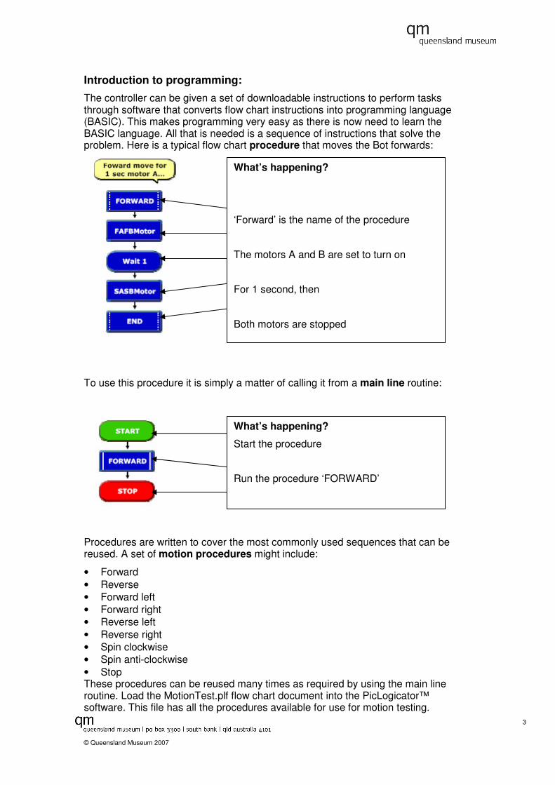
The controller can be given a set of downloadable instructions to perform tasks through software that converts flow chart instructions into programming language (BASIC). This makes programming very easy as there is now need to learn the BASIC language. All that is needed is a sequence of instructions that solve the problem. Here is a typical flow chart procedure that moves the Bot forwards:
To use this procedure it is simply a matter of calling it from a main line routine:
Procedures are written to cover the most commonly used sequences that can be reused. A set of motion procedures might include:
• Forward • Reverse • Forward left • Forward right • Reverse left • Reverse right • Spin clockwise • Spin anti-clockwise • Stop These procedures can be reused many times as required by using the main line routine. Load the MotionTest.plf flow chart document into the PicLogicator™ software. This file has all the procedures available for use for motion testing.
What’s happening?
‘Forward’ is the name of the procedure
The motors A and B are set to turn on
For 1 second, then
Both motors are stopped
What’s happening?
Start the procedure
Run the procedure ‘FORWARD’

4
© Queensland Museum 2007
MotionTest.plf segment

5
© Queensland Museum 2007
INPUT
SENSORS
PROCESSOR
Light
Temperature
Colour
Sound
Distance
Touch
POWER SUPPLY
Battery pack
Diode regulator
Solar cells
OUTPUT
MOSFET POWER SWITCH
HIGH POWER
Siren
Control valve
Heating panel
Stepper
Motor A
Motor B
Fan
Tri-colour LEDs
LED light
B.2
B.0
B.1
B.2
B.5 – B.7
B.3
B.4
12V 1A DC
MOS Output 12VDC
MOS Output 12VDC
MOS Output 12VDC
MOS Output 12VDC
A.0 – A.2
A.0 – A.2
A.0 – A.2
A.0 – A.2
A.0 – A.2
A.6 – A.7
Analogue Sensors
Digital Sensor

6
© Queensland Museum 2007
How to use the PicLogicator™ software:
5. Download after connecting cable to Pic controller
1. Drag flowchart elements to main line
Available procedures
2. Double click and set properties
3. Join elements with arrows
5 easy steps to programming: 1. Drag the elements of the flow chart from the right hand column to under the
icon.
2. Set the properties of the elements by double clicking. In this case, the DoProcedure element properties allows for selection of the procedure to use. These are the procedures that have previously been created on the page. All procedures that are created will appear in the list.
3. Join the elements using the line drawing tool. Right click on the first element then drag to the last element and then right click again.
4. Test the procedure by clicking on the green arrow button. This should show what will happen once the program is downloaded.
5. Download the program onto the pic controller chip. Make sure the controller is switched on and the serial cable is connected from the computer to the controller.
4. Test button

7
© Queensland Museum 2007
This is how the ‘DEBUG’ dialog box should look. The value of ‘A’ could be a range of values depending on the level of background noise.
Let’s Dance Your Challenge Program Bot to dance in time with selected music What you need
1 Sensors Sound Sensor
2 Outputs Motor A&B on Bot B0, B1
3 Processing Calibrate.plf
lets dance.plf
4 Other • Music with a range of sound levels such as Rock Music or Techno Beat or any suitable dance music. Choose music with a range of sound frequencies rather just your favourite track.
• CD Player
What you do
Phase 1 Calibration Phase:
1. Attach sound sensor to Port A0.
2. Load calibrate.plf into PicLogicator™ software
3. Check that ‘ANALOGCAL’ is the chosen procedure then download to Bot
4. Select ‘PIC’ from menu, then choose ‘DEBUG’.
5. Test that your sensor is working by clapping loudly near the sensor, to see the value of ‘A’ change in the dialog box.
6. Now start your music and write down the varying values of ‘A’ as the music changes. (record values in a table)
Highest value Lowest value Most often value
This completes the calibration phase
8
© Queensland Museum 2007
Phase 2 Making and Testing:
1. Load the lets dance.plf into PicLogicator™ software
2. Choose 4 values between the lowest and highest values to add to the decision boxes.
eg. For the range 200 – 250 use values 200, 210, 220, 230, 240 and 250.
3. Choose a spin routine for the most often value. Eg. 210 - spinc
4. Save your project under a name of your choice
5. Download your program onto Bot
6. Start the music, push the green go button on Bot and watch the fun.
Phase 3 Debug:
At all times ensure the batteries are fully charged as this may alter the performance of Bot.
1. Problem: Bot not responding to the music
� Check that the music is loud enough
� Move Bot closer to speaker
� Turn up the volume
� Check the sensor lead is firmly plugged into input ‘A0’
2. Problem: Bot only moves in 1 or 2 different ways
� Check the highest and lowest values of ‘A’.
� Now scale all the alternative values of ‘A’ to occur between these values.
� Check that the music provides a range of values for ‘A’. The larger the range the better.
3. Problem: Bot keeps moving off the dance floor area in either forward or reverse direction.
� Check the values of ’A’ for the most commonly occurring value.
� Use this value of ‘A’ to use the spin procedure. This should keep Bot on the dance floor.
To do this, double click in the ‘decision box’ to adjust values.
9
© Queensland Museum 2007
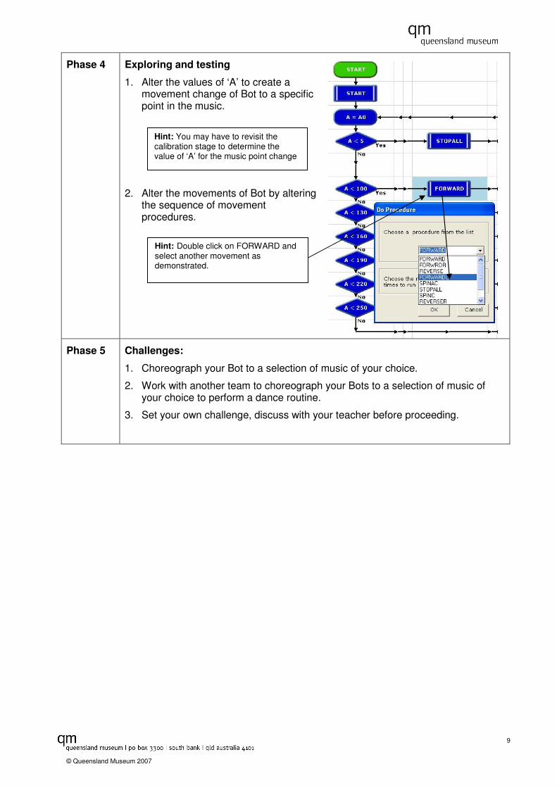
Phase 4 Exploring and testing
1. Alter the values of ‘A’ to create a movement change of Bot to a specific point in the music.
2. Alter the movements of Bot by altering the sequence of movement procedures.
Phase 5 Challenges:
1. Choreograph your Bot to a selection of music of your choice.
2. Work with another team to choreograph your Bots to a selection of music of your choice to perform a dance routine.
3. Set your own challenge, discuss with your teacher before proceeding.
Hint: Double click on FORWARD and select another movement as demonstrated.
Hint: You may have to revisit the calibration stage to determine the value of ‘A’ for the music point change

10
© Queensland Museum 2007
The Heat Is On Your Challenge Provide a warning alarm for a controlled temperature environment such as an egg incubator What you need
1 Sensors Temperature
2 Outputs On board piezo buzzer
On board Light Emitting Diode (LED)
3 Processing Calibrate.plf
Thermo.plf
Thermofan.plf
4 Other Stand alone fan (computer fan)
Mosfet power supply + 12 V power adaptor
Heating panel
Thermofanheater.plf
What you do
Phase 1 Calibration Phase:
1. Attach Temperature sensor to Port A0
2. Load calibrate.plf into PicLogicator™ software
3. Check that ‘TEMPCAL’ is the chosen procedure then download to Bot
4. Select ‘PIC’ from menu, then select ‘DEBUG’
5. Test that your sensor is working by holding the sensor between two fingers and watch the temperature rise.
6. Record room temperature and highest temperature values in a table.
This completes the calibration phase
This is how the ‘DEBUG’ dialog box should look. The value of ‘A’ should be close to room temperature.
11
© Queensland Museum 2007
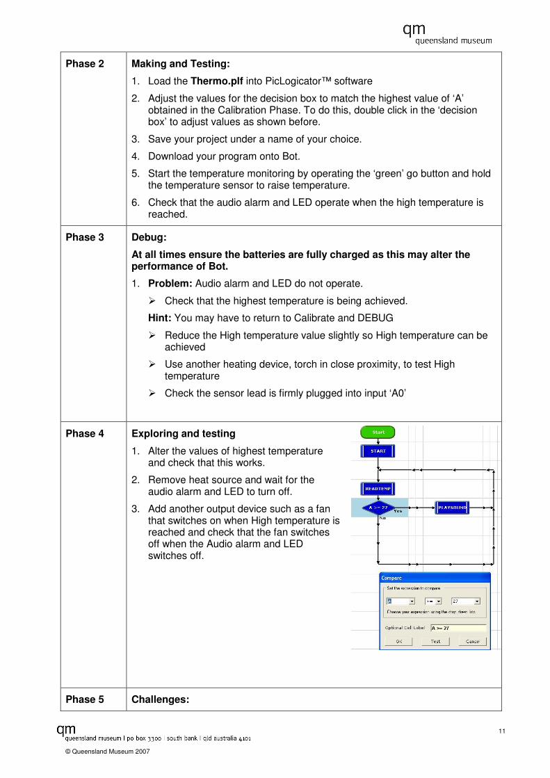
Phase 2 Making and Testing:
1. Load the Thermo.plf into PicLogicator™ software
2. Adjust the values for the decision box to match the highest value of ‘A’ obtained in the Calibration Phase. To do this, double click in the ‘decision box’ to adjust values as shown before.
3. Save your project under a name of your choice.
4. Download your program onto Bot.
5. Start the temperature monitoring by operating the ‘green’ go button and hold the temperature sensor to raise temperature.
6. Check that the audio alarm and LED operate when the high temperature is reached.
Phase 3 Debug:
At all times ensure the batteries are fully charged as this may alter the performance of Bot.
1. Problem: Audio alarm and LED do not operate.
� Check that the highest temperature is being achieved.
Hint: You may have to return to Calibrate and DEBUG
� Reduce the High temperature value slightly so High temperature can be achieved
� Use another heating device, torch in close proximity, to test High temperature
� Check the sensor lead is firmly plugged into input ‘A0’
Phase 4 Exploring and testing
1. Alter the values of highest temperature and check that this works.
2. Remove heat source and wait for the audio alarm and LED to turn off.
3. Add another output device such as a fan that switches on when High temperature is reached and check that the fan switches off when the Audio alarm and LED switches off.
Phase 5 Challenges:

12
© Queensland Museum 2007
1. Switch a fan on so that temperature is maintained at no more than 40 C above normal room temperature. Hint: Use thermofan.plf as a basis for procedures.
2. Modify the program so that the temperature is maintained at no more than 40 C above normal room temperature. Hint: use thermofan.plf and a heater panel.
3. Set your own challenge; discuss this with your teacher before proceeding

13
© Queensland Museum 2007
Dodgem Cars Your Challenge Design and construct a vehicle that can navigate around randomly placed obstacles. This vehicle is the forerunner for the first “crash proof” vehicle. What you need
1 Sensors Distance sensor
2 Outputs Motors A & B
3 Processing Calibrate.plf
Avoid.plf
4 Other Design your own obstacle maze to navigate through. Hint: A simple approach would be to use text books as obstacles.
What you do
Phase 1 Calibration Phase:
1. Attach Distance sensor to Port A0
2. Load calibrate.plf into PicLogicator™ software
3. Check that ‘ANALOGCAL’ is the chosen procedure then download to Bot.
4. Select ‘PIC’ from menu, then select ‘DEBUG’.
5. Test that your sensor is working by varying the distance of the object from the sensor.
6. Record values of ‘A’ for different distances from the object in a table.
Object Distance (cm)
10 15 20 25 30 35
This is how the ‘DEBUG’ dialog box should look. The value of ‘A’ could be a range of values depending on distance of sensor to the object.
14
© Queensland Museum 2007
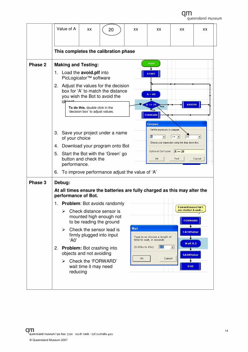
Value of A xx
xx xx xx xx
This completes the calibration phase
Phase 2 Making and Testing:
1. Load the avoid.plf into PicLogicator™ software
2. Adjust the values for the decision box for ‘A’ to match the distance you wish the Bot to avoid the object.
3. Save your project under a name of your choice
4. Download your program onto Bot
5. Start the Bot with the ‘Green’ go button and check the performance.
6. To improve performance adjust the value of ‘A’
Phase 3 Debug:
At all times ensure the batteries are fully charged as this may alter the performance of Bot.
1. Problem: Bot avoids randomly
� Check distance sensor is mounted high enough not to be reading the ground
� Check the sensor lead is firmly plugged into input ‘A0’
2. Problem: Bot crashing into objects and not avoiding
� Check the ‘FORWARD’ wait time it may need reducing
20
To do this, double click in the ‘decision box’ to adjust values.

15
© Queensland Museum 2007
Phase 4 Exploring and testing
1. Alter the procedure for avoiding the object to another procedure on the program sheet.
2. Test and check the changes in performance.
Phase 5 Challenges:
1. Find the most efficient way to navigate a series of obstacles. Hint: You may need to try different avoidance procedures.
2. Combine this with the ‘Heat is On’ worksheet to design a machine to search for and measure the temperature of objects. This device could be used to detect and react to specific temperatures.
3. Set your own challenge, discuss with teacher before proceeding
To do this, double click on the AVOIDR procedure box then select another procedure.
16
© Queensland Museum 2007
A Light on Activity Your Challenge A security light needs to switch on automatically at dusk each day and turn off automatically at dawn each day. What you need
1 Sensors Light sensor (photo transistor)
2 Outputs 2 x LED Lights (You may need to use one of the onboard LED’s as one output).
3 Processing Calibrate.plf
Light.plf
4 Other Light Source (torch)
Container of clean water and a container of dirty water for Challenge 2.
What you do
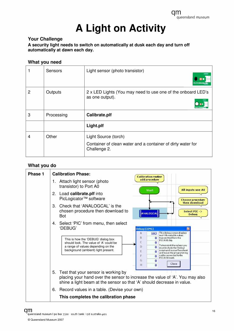
Phase 1 Calibration Phase:
1. Attach light sensor (photo transistor) to Port A0
2. Load calibrate.plf into PicLogicator™ software
3. Check that ‘ANALOGCAL’ is the chosen procedure then download to Bot
4. Select ‘PIC’ from menu, then select ‘DEBUG’
5. Test that your sensor is working by placing your hand over the sensor to increase the value of ‘A’. You may also shine a light beam at the sensor so that ‘A’ should decrease in value.
6. Record values in a table. (Devise your own)
This completes the calibration phase
This is how the ‘DEBUG’ dialog box should look. The value of ‘A’ could be a range of values depending on the background (ambient) light present.
17
© Queensland Museum 2007
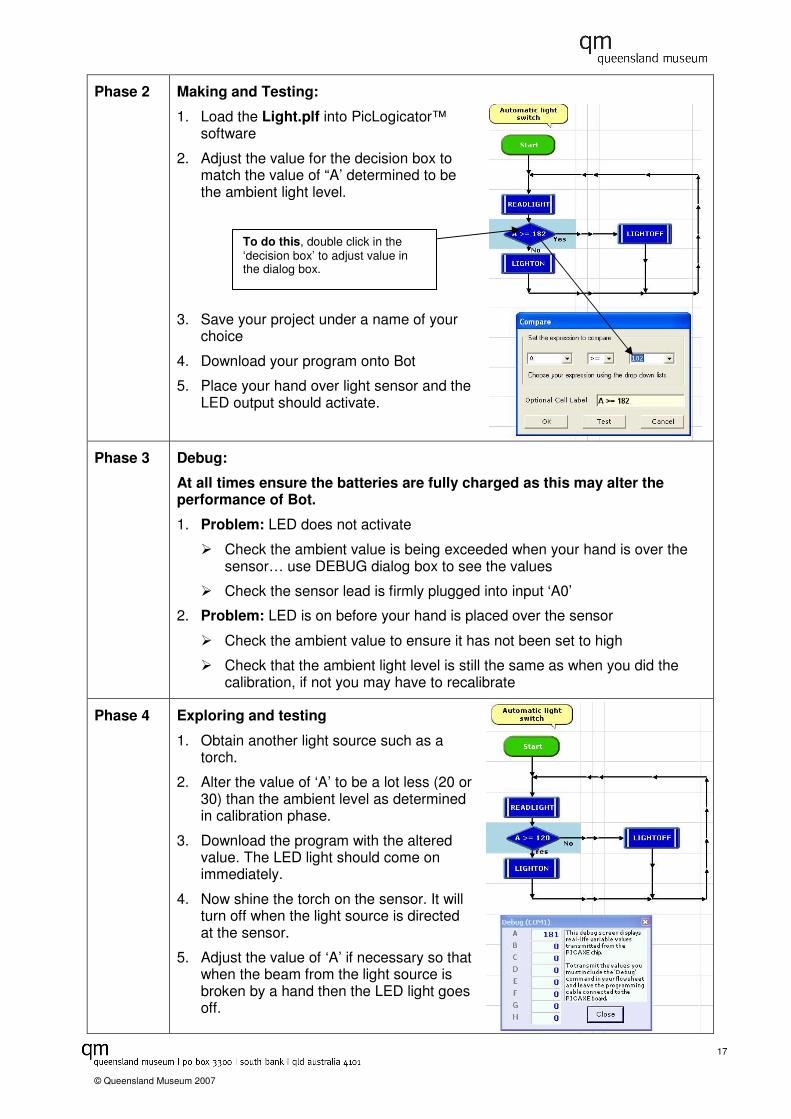
Phase 2 Making and Testing:
1. Load the Light.plf into PicLogicator™ software
2. Adjust the value for the decision box to match the value of “A’ determined to be the ambient light level.
3. Save your project under a name of your choice
4. Download your program onto Bot
5. Place your hand over light sensor and the LED output should activate.
Phase 3 Debug:
At all times ensure the batteries are fully charged as this may alter the performance of Bot.
1. Problem: LED does not activate
� Check the ambient value is being exceeded when your hand is over the sensor… use DEBUG dialog box to see the values
� Check the sensor lead is firmly plugged into input ‘A0’
2. Problem: LED is on before your hand is placed over the sensor
� Check the ambient value to ensure it has not been set to high
� Check that the ambient light level is still the same as when you did the calibration, if not you may have to recalibrate
Phase 4 Exploring and testing
1. Obtain another light source such as a torch.
2. Alter the value of ‘A’ to be a lot less (20 or 30) than the ambient level as determined in calibration phase.
3. Download the program with the altered value. The LED light should come on immediately.
4. Now shine the torch on the sensor. It will turn off when the light source is directed at the sensor.
5. Adjust the value of ‘A’ if necessary so that when the beam from the light source is broken by a hand then the LED light goes off.
To do this, double click in the ‘decision box’ to adjust value in the dialog box.
18
© Queensland Museum 2007
Phase 5 Challenges:
1. Burglar Alarm-Alter the program so that if a light beam is broken the LED light and Alarm (audio alarm on BOT) is turned on. Hint: Refer to the Heat Is On activity for how the audio alarm works.
2. Dirty Water Detector-Construct a method for Bot to detect if dirty water is passing the Light sensor. Turn on a white light for clean water and a red light for dirty water, you may wish to use an audio alarm also. Hint: To detect the water clarity, try shining a light through containers of clean and dirty water. Calibrate the sensor to read the different clarities of the water.
3. Set your own challenge; discuss this with your teacher before proceeding.