teaching plc programming and industrial automation in ... · teaching plc programming and...
TRANSCRIPT
Paper ID #13212
Teaching PLC Programming and Industrial Automation in Mechatronics En-gineering
Dr. Shouling He, Vaughn College of Aeronautics & Technology
Dr. Shouling He is an associate professor of Engineering and Technology at Vaughn College of Aero-nautics and Technology, where she is teaching the courses in Mechatronics Engineering and ElectricalEngineering Technology. Her research interests include modeling and simulation, microprocessors andPLCs, control system designs and Robotics. She has published more than 45 journal and conferencepapers in these research areas.
Dr. Hossein Rahemi, Vaughn College of Aeronautics & Technology
Dr. Hossein Rahemi is a professor and department chair of Engineering and Technology at Vaughn Col-lege of Aeronautics & Technology. He is the author of two books, Vaughn College Journal of Engineeringand Technology (VCJET), numerous conference papers in the areas of solid mechanics, computationalmechanics, vibration analysis, fracture mechanics and reliability analysis. He is also a principle investi-gator for the NSF S-STEM grant and the HIS-STEM grant and a student adviser for a number of technicalpapers in the areas of mechanics, robotics and industrial automation.
Prof. Khalid Mouaouya, Vaughn College of Aeronautics & Technology
Khalid Mouaouya, associate professor of engineering and technology, received his BT from Collegeof Aeronautics and Technology, his MME from Manhattan College, MCE -Professional Degree- fromColumbia University. His teaching interests involved finding ways to make students understand and ap-preciate the role of mathematics in solving different and complex engineering problems.
c©American Society for Engineering Education, 2015
Page 26.1483.1
Teaching PLC Programming and Industrial Automation in
Mechatronics Engineering
Abstract
This paper presents an approach to teach programmable logic controller (PLC) programming and
industrial automation to students in Mechatronics Engineering program at Vaughn College of
Aeronautics and Technology. The first course, i.e. PLC Programming, introduces texted
languages, such as instruction list and structured text, according to IEC61131-3 standard so that
students can learn a fundamental concept about PLC hardware and software using the standards-
based programming languages. The advanced course, Industrial Automation, focuses on teaching
students the sequence control concept and problem solving strategy, where Sequential Function
Chart, Ladder Diagram and Function Block Diagram are used to put the design of industrial
manufacturing assembly line into operation. The classes have been taught in project based
approach and the kinesthetic learning style has been adopted throughout all laboratory sections.
From students’ comments, the teaching approach was very successful. By the end of the
academic year, students have developed their own various projects using the knowledge they
learned from PLC Programming and Industrial Automation courses. Some of the projects have
been further advanced as a student research paper published at the college technology day
conference, ASEE regional conferences or the Latin American Caribbean Conference for
Engineering and Technology. Moreover, these courses are intended to enhance career
opportunities for the students in Mechatronics Engineering program. Currently some of our
graduates have chosen their careers in the area of PLC programming and industrial automation.
Keywords: PLC Programming, Sequence Control, Industrial Automation.
Page 26.1483.2
Introduction
Programmable Logic Controller (PLC) is an industrial computer which takes in data from
sensors and sends commands to actuators to implement complex industrial controls. Since PLC
controllers are highly configurable and reliable, they have been widely used in various industries
ranging from automotive1, nuclear power and energy systems
2, material handling
3 to food
manufacturing4. Due to higher demands in industries, PLC programming course as well as the
fundamentals of industrial automation has been introduced and taught by many universities and
colleges with addressing various applications and practical issues5,6
.
PLC programming has been taught using Ladder Diagram since PLCs were introduced in earlier
1970s. The programming technique was designed following two-wire relay control logic
schematics. The process begins with entering the first rung to satisfy the first output requirement
and the rungs are continually entered until the solution to the problem under investigation is
reached. The special programming approach makes the electricians who are responsible for the
maintenance of a PLC control system easy for troubleshooting and updating programs due to the
similarity between the relay control hardware and software schematic. However, for the students
in Mechatronics Engineering at Vaughn College, although they have taken a 3-credit DC/AC
Circuits course and a 3-credit Electronics course (including laboratory exercises), their
knowledge in electrical engineering is still very limited since they need to learn courses from
mechanics, thermal science and material science as well as computer engineering. Therefore, the
relay control schematic is a new topic for the students in understanding the hardware and
software programming.
On the other hand, the students in the program have had some knowledge in texted programming
languages since they learned MATLAB programming through the computational method course
in mechanical engineering and assembly language through the microprocessors course in
computer engineering. Under the circumstance, teaching the logic programming in PLCs can be
easier if starting from texted languages. Therefore, the texted languages designated by the
IEC61131-1 standard, such as Instruction List (IL) and Structured Text (ST), have been taught in
the first course, PLC Programming, at the college. After students have mastered the fundamental
knowledge needed for programming industrial automation devices, the Sequential Function
Chart (SFC), Ladder Diagram (LD) and Function Block Diagram (FCB) are taught in the
advanced course, Industrial Automation, where Siemens Step 7 PLCs have been used.
Particularly, the SFC chart has been taught as an approach of developing a complex algorithm so
that students can first develop the pseudo code as an SFC-like diagram and then implement it in
LD or FCB diagram7.
The courses, PLC Programming and Industrial Automation, have been taught at the college since
2010. As a result, students have developed various course projects which aim to solve problems
in the real world using PLCs. The corresponding educational research papers have been
successfully presented in several conferences. Furthermore, a number of students have landed
jobs in the industry as control and automation engineers.
This paper will present the result that we got from teaching the courses, which is organized as
follows. In Section 2, the course schedule for the first course PLC programming is introduced.
Page 26.1483.3
The course layout for the advanced course, Industrial Automation, is presented in Section 3 and
the course survey as well as the students' papers in conferences are discussed in Section 4,
respectively. The approach to teach PLC programming and industrial automation is concluded in
Section 5.
Course Setup for PLC Programming
At Vaughn College, the PLC Programming course is scheduled in the second semester of
junior year. As Mechatronics Engineering students in junior year standing, they have learned
MATLAB programming, assembly language and C language programming from the courses as
MATLAB, C++ Programming, Computational Methods in Engineering, and Microprocessors.
With the knowledge background, the main goal for the PLC programming course is to let
students understand the fundamental structure of PLC technology and programming skills used
in PLCs in the automation and manufacturing industry, such as addressing mode in PLC
programming, timers and counters, PLC digital input/output module and analog input/output
module, etc. Furthermore, students are required to solve some practical problems through
programming the PLCs. By the end of the course, the concept of Sequential Function Chart is
taught as an algorithm development approach so that students are ready to be engaged in
developing a PLC control logic for a complicated industrial automation system. Based on the
goals, the course topics and laboratory project exercises are scheduled as shown in Table1.
Table 1: Course Topics and Lecture Hours Devoted to Each Topic
Week Hour Topic
1 2 PLC technique overview.
2-3 4 Addressing mode in PLC programming, basic logic programming in Instruction
List and Structured Text languages
4 2 Combination of Boolean operations and storing elements
5 2 Function blocks, edge-trigged functions, timers including switch-on delay, switch
off delay and pulse function
6 2 Up counters, down counter, up/down counter with applications
7 2 Programming structure - function calls and jump statements
8 Course Review and Midterm
9 2 Analog to digital conversion and digital to analog conversion in PLC program.
10 2 Conveyor belt station: basic sensors and actuators in manufacturing industry
11 – 12 4 Sequence control development and programming.
13 – 14 4 Introduction to PLC network communication and PROFIBUS configuration
15 Course Review and Final Exam
In the laboratory exercise sections, the Uni-trainer as well as the corresponding conveyor belt
system, provided by Lucas Nuelle (LN) Ltd8, is used, which is shown in Figure1. According to
the course topics, the laboratory exercises are arranged as a sequence of small homework
Page 26.1483.4
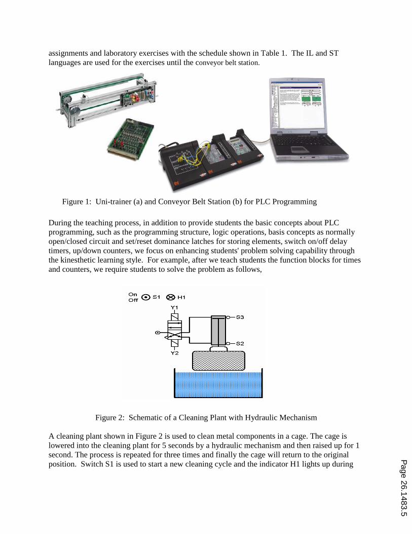
assignments and laboratory exercises with the schedule shown in Table 1. The IL and ST
languages are used for the exercises until the conveyor belt station.
During the teaching process, in addition to provide students the basic concepts about PLC
programming, such as the programming structure, logic operations, basis concepts as normally
open/closed circuit and set/reset dominance latches for storing elements, switch on/off delay
timers, up/down counters, we focus on enhancing students' problem solving capability through
the kinesthetic learning style. For example, after we teach students the function blocks for times
and counters, we require students to solve the problem as follows,
Figure 2: Schematic of a Cleaning Plant with Hydraulic Mechanism
A cleaning plant shown in Figure 2 is used to clean metal components in a cage. The cage is
lowered into the cleaning plant for 5 seconds by a hydraulic mechanism and then raised up for 1
second. The process is repeated for three times and finally the cage will return to the original
position. Switch S1 is used to start a new cleaning cycle and the indicator H1 lights up during
Figure 1: Uni-trainer (a) and Conveyor Belt Station (b) for PLC Programming
(a)
(b)
Page 26.1483.5
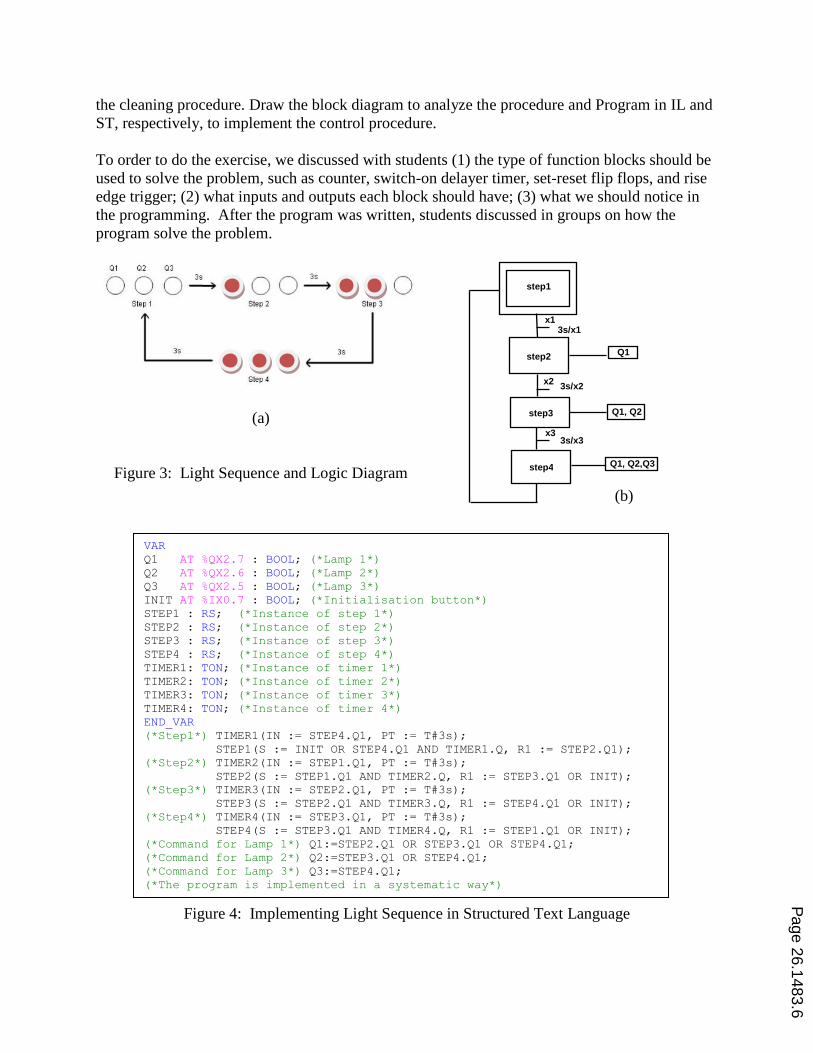
the cleaning procedure. Draw the block diagram to analyze the procedure and Program in IL and
ST, respectively, to implement the control procedure.
To order to do the exercise, we discussed with students (1) the type of function blocks should be
used to solve the problem, such as counter, switch-on delayer timer, set-reset flip flops, and rise
edge trigger; (2) what inputs and outputs each block should have; (3) what we should notice in
the programming. After the program was written, students discussed in groups on how the
program solve the problem.
(a)
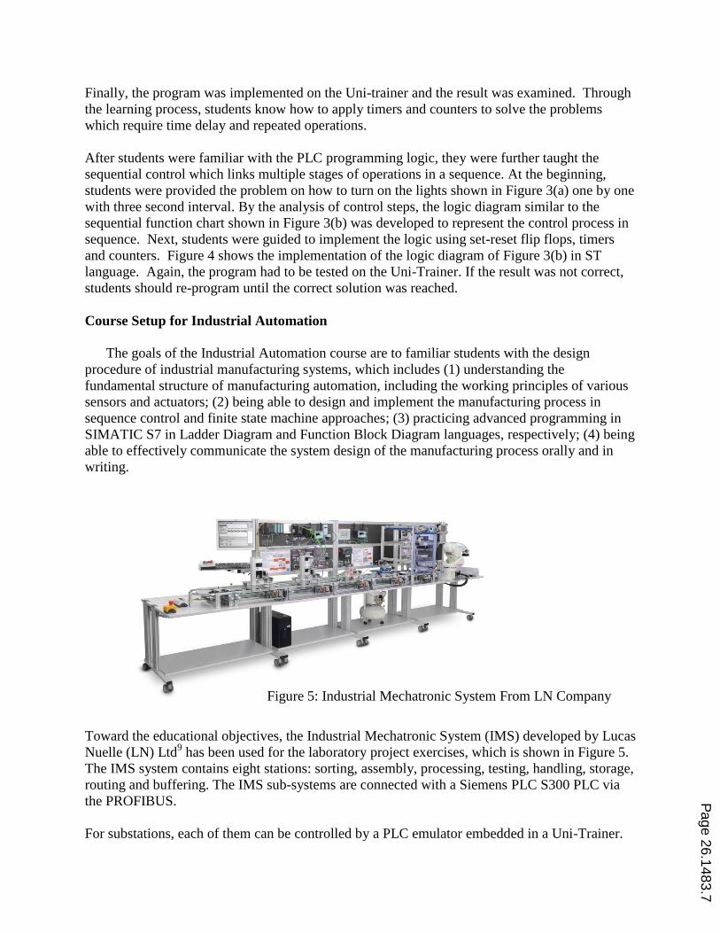
Figure 3: Light Sequence and Logic Diagram
Figure 4: Implementing Light Sequence in Structured Text Language
step1
Q1, Q2,Q3
step2
step3
x1
3s/x1
3s/x2
Q1, Q2
Q1
x3 3s/x3
x2
step4
(b)
VAR
Q1 AT %QX2.7 : BOOL; (*Lamp 1*)
Q2 AT %QX2.6 : BOOL; (*Lamp 2*)
Q3 AT %QX2.5 : BOOL; (*Lamp 3*)
INIT AT %IX0.7 : BOOL; (*Initialisation button*)
STEP1 : RS; (*Instance of step 1*)
STEP2 : RS; (*Instance of step 2*)
STEP3 : RS; (*Instance of step 3*)
STEP4 : RS; (*Instance of step 4*)
TIMER1: TON; (*Instance of timer 1*)
TIMER2: TON; (*Instance of timer 2*)
TIMER3: TON; (*Instance of timer 3*)
TIMER4: TON; (*Instance of timer 4*)
END_VAR
(*Step1*) TIMER1(IN := STEP4.Q1, PT := T#3s);
STEP1(S := INIT OR STEP4.Q1 AND TIMER1.Q, R1 := STEP2.Q1);
(*Step2*) TIMER2(IN := STEP1.Q1, PT := T#3s);
STEP2(S := STEP1.Q1 AND TIMER2.Q, R1 := STEP3.Q1 OR INIT);
(*Step3*) TIMER3(IN := STEP2.Q1, PT := T#3s);
STEP3(S := STEP2.Q1 AND TIMER3.Q, R1 := STEP4.Q1 OR INIT);
(*Step4*) TIMER4(IN := STEP3.Q1, PT := T#3s);
STEP4(S := STEP3.Q1 AND TIMER4.Q, R1 := STEP1.Q1 OR INIT);
(*Command for Lamp 1*) Q1:=STEP2.Q1 OR STEP3.Q1 OR STEP4.Q1;
(*Command for Lamp 2*) Q2:=STEP3.Q1 OR STEP4.Q1;
(*Command for Lamp 3*) Q3:=STEP4.Q1;
(*The program is implemented in a systematic way*)
Page 26.1483.6
Finally, the program was implemented on the Uni-trainer and the result was examined. Through
the learning process, students know how to apply timers and counters to solve the problems
which require time delay and repeated operations.
After students were familiar with the PLC programming logic, they were further taught the
sequential control which links multiple stages of operations in a sequence. At the beginning,
students were provided the problem on how to turn on the lights shown in Figure 3(a) one by one
with three second interval. By the analysis of control steps, the logic diagram similar to the
sequential function chart shown in Figure 3(b) was developed to represent the control process in
sequence. Next, students were guided to implement the logic using set-reset flip flops, timers
and counters. Figure 4 shows the implementation of the logic diagram of Figure 3(b) in ST
language. Again, the program had to be tested on the Uni-Trainer. If the result was not correct,
students should re-program until the correct solution was reached.
Course Setup for Industrial Automation
The goals of the Industrial Automation course are to familiar students with the design
procedure of industrial manufacturing systems, which includes (1) understanding the
fundamental structure of manufacturing automation, including the working principles of various
sensors and actuators; (2) being able to design and implement the manufacturing process in
sequence control and finite state machine approaches; (3) practicing advanced programming in
SIMATIC S7 in Ladder Diagram and Function Block Diagram languages, respectively; (4) being
able to effectively communicate the system design of the manufacturing process orally and in
writing.
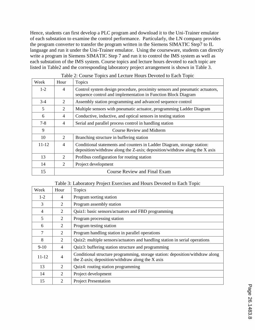
Toward the educational objectives, the Industrial Mechatronic System (IMS) developed by Lucas
Nuelle (LN) Ltd9 has been used for the laboratory project exercises, which is shown in Figure 5.
The IMS system contains eight stations: sorting, assembly, processing, testing, handling, storage,
routing and buffering. The IMS sub-systems are connected with a Siemens PLC S300 PLC via
the PROFIBUS.
For substations, each of them can be controlled by a PLC emulator embedded in a Uni-Trainer.
Figure 5: Industrial Mechatronic System From LN Company
Page 26.1483.7
Hence, students can first develop a PLC program and download it to the Uni-Trainer emulator
of each substation to examine the control performance. Particularly, the LN company provides
the program converter to transfer the program written in the Siemens SIMATIC Step7 to IL
language and run it under the Uni-Trainer emulator. Using the courseware, students can directly
write a program in Siemens SIMATIC Step 7 and run it to control the IMS system as well as
each substation of the IMS system. Course topics and lecture hours devoted to each topic are
listed in Table2 and the corresponding laboratory project arrangement is shown in Table 3.
Table 2: Course Topics and Lecture Hours Devoted to Each Topic
Week Hour Topics
1-2 4 Control system design procedure, proximity sensors and pneumatic actuators,
sequence control and implementation in Function Block Diagram
3-4 2 Assembly station programming and advanced sequence control
5 2 Multiple sensors with pneumatic actuator, programming Ladder Diagram
6 4 Conductive, inductive, and optical sensors in testing station
7-8 4 Serial and parallel process control in handling station
9 Course Review and Midterm
10 2 Branching structure in buffering station
11-12 4 Conditional statements and counters in Ladder Diagram, storage station:
deposition/withdraw along the Z-axis; deposition/withdraw along the X axis
13 2 Profibus configuration for routing station
14 2 Project development
15 Course Review and Final Exam
Table 3: Laboratory Project Exercises and Hours Devoted to Each Topic
Week Hour Topics
1-2 4 Program sorting station
3 2 Program assembly station
4 2 Quiz1: basic sensors/actuators and FBD programming
5 2 Program processing station
6 2 Program testing station
7 2 Program handling station in parallel operations
8 2 Quiz2: multiple sensors/actuators and handling station in serial operations
9-10 4 Quiz3: buffering station structure and programming
11-12 4 Conditional structure programming, storage station: deposition/withdraw along
the Z-axis; deposition/withdraw along the X axis
13 2 Quiz4: routing station programming
14 2 Project development
15 2 Project Presentation
Page 26.1483.8
For the laboratory project exercises, five high-quality laboratory project reports are required to
be written plus a course project report. The topic of the course project can be chosen by students.
The problems existed in industries are encouraged to choose and solve. In addition to the course
project report, a course presentation will be held by the end of the semester. Students are
required to present the project design and demonstrate the successful implementation of the
developed PLC program.
The lecture of each substation focuses on certain new knowledge, for example new sensors or
pneumatic/hydraulic actuators with various types of valves, new programming language or new
programming skills, such as parallel programming and conditional structure. For each substation,
students develop the PLC program and test it by the following steps: (1) Examine the
functionality of the station and the corresponding inputs and outputs; (2) Identify the number of
stages to complete the procedure and develop the logic diagram or table to represent the stage
commands and conditions; (3) Program according to the logic diagram; (4) Test the program and
troubleshoot.
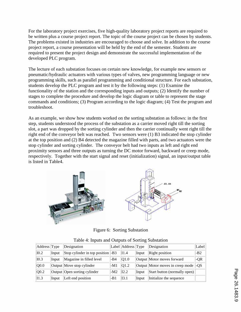
As an example, we show how students worked on the sorting substation as follows: in the first
step, students understood the process of the substation as a carrier moved right till the sorting
slot, a part was dropped by the sorting cylinder and then the carrier continually went right till the
right end of the conveyor belt was reached. Two sensors were (1) B3 indicated the stop cylinder
at the top position and (2) B4 detected the magazine filled with parts, and two actuators were the
stop cylinder and sorting cylinder. The conveyor belt had two inputs as left and right end
proximity sensors and three outputs as turning the DC motor forward, backward or creep mode,
respectively. Together with the start signal and reset (initialization) signal, an input/output table
is listed in Table4.
Figure 6: Sorting Substation
Table 4: Inputs and Outputs of Sorting Substation
Address Type Designation Label Address Type Designation Label
I0.2 Input Stop cylinder in top position -B3 I1.4 Input Right position -B2
I0.3 Input Magazine in filled level -B4 Q1.0 Output Motor moves forward -QR
Q0.0 Output Move stop cylinder -M1 Q1.2 Output Motor moves in creep mode -QS
Q0.2 Output Open sorting cylinder -M2 I2.2 Input Start button (normally open)
I1.3 Input Left end position -B1 I3.1 Input Initialize the sequence
Page 26.1483.9
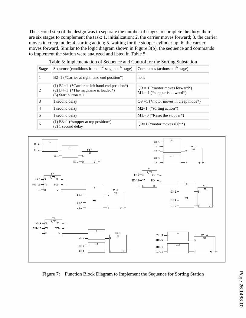
The second step of the design was to separate the number of stages to complete the duty: there
are six stages to complement the task: 1. initialization; 2. the carrier moves forward; 3. the carrier
moves in creep mode; 4. sorting action; 5. waiting for the stopper cylinder up; 6. the carrier
moves forward. Similar to the logic diagram shown in Figure 3(b), the sequence and commands
to implement the station were analyzed and listed in Table 5.
Table 5: Implementation of Sequence and Control for the Sorting Substation
Figure 7: Function Block Diagram to Implement the Sequence for Sorting Station
Stage Sequence (conditions from i-1th
stage to ith
stage) Commands (actions at ith
stage)
1 B2=1 (*Carrier at right hand end position*) none
2
(1) B1=1 (*Carrier at left hand end position*)
(2) B4=1 (*The magazine is loaded*)
(3) Start button = 1.
QR = 1 (*motor moves forward*)
M1:= 1 (*stopper is downed*)
3 1 second delay QS =1 (*motor moves in creep mode*)
4 1 second delay M2=1 (*sorting action*)
5 1 second delay M1:=0 (*Reset the stopper*)
6 (1) B3=1 (*stopper at top position*)
(2) 1 second delay QR=1 (*motor moves right*)
Page 26.1483.10
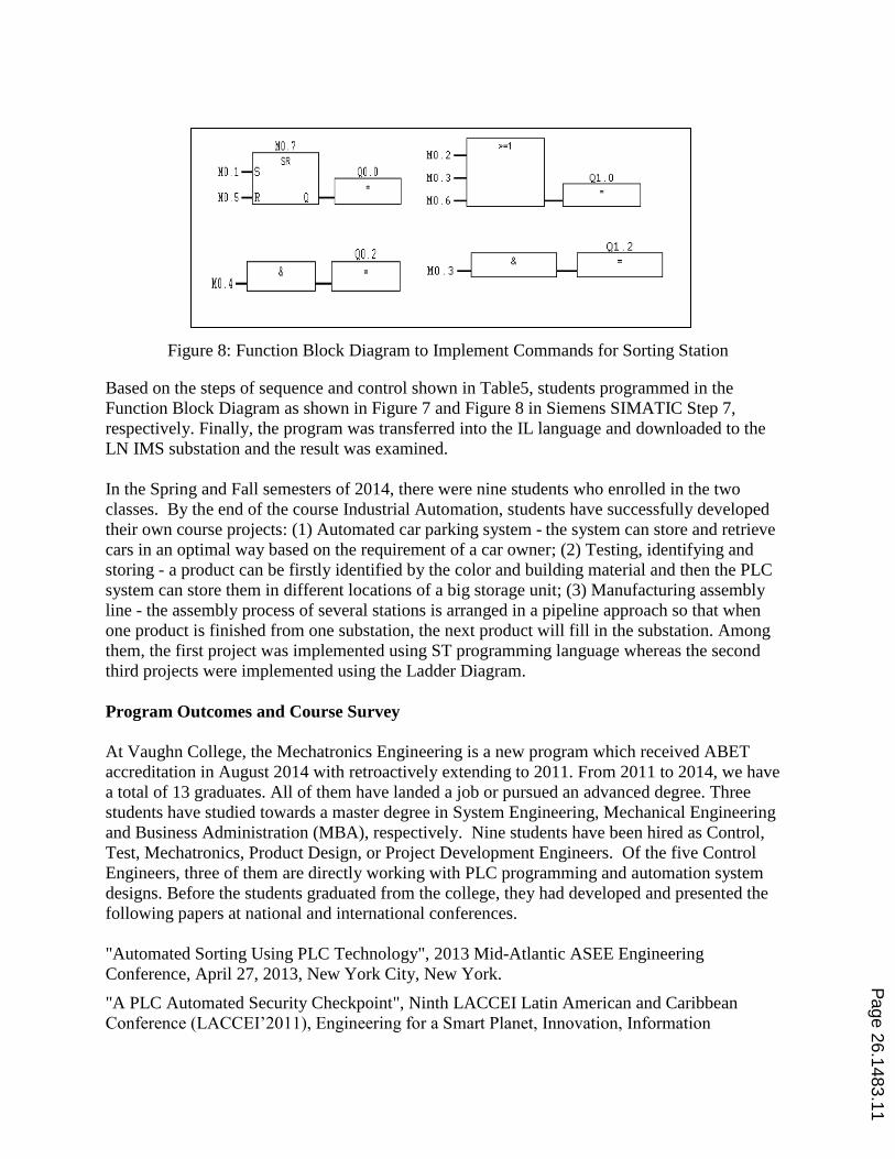
Figure 8: Function Block Diagram to Implement Commands for Sorting Station
Based on the steps of sequence and control shown in Table5, students programmed in the
Function Block Diagram as shown in Figure 7 and Figure 8 in Siemens SIMATIC Step 7,
respectively. Finally, the program was transferred into the IL language and downloaded to the
LN IMS substation and the result was examined.
In the Spring and Fall semesters of 2014, there were nine students who enrolled in the two
classes. By the end of the course Industrial Automation, students have successfully developed
their own course projects: (1) Automated car parking system - the system can store and retrieve
cars in an optimal way based on the requirement of a car owner; (2) Testing, identifying and
storing - a product can be firstly identified by the color and building material and then the PLC
system can store them in different locations of a big storage unit; (3) Manufacturing assembly
line - the assembly process of several stations is arranged in a pipeline approach so that when
one product is finished from one substation, the next product will fill in the substation. Among
them, the first project was implemented using ST programming language whereas the second
third projects were implemented using the Ladder Diagram.
Program Outcomes and Course Survey
At Vaughn College, the Mechatronics Engineering is a new program which received ABET
accreditation in August 2014 with retroactively extending to 2011. From 2011 to 2014, we have
a total of 13 graduates. All of them have landed a job or pursued an advanced degree. Three
students have studied towards a master degree in System Engineering, Mechanical Engineering
and Business Administration (MBA), respectively. Nine students have been hired as Control,
Test, Mechatronics, Product Design, or Project Development Engineers. Of the five Control
Engineers, three of them are directly working with PLC programming and automation system
designs. Before the students graduated from the college, they had developed and presented the
following papers at national and international conferences.
"Automated Sorting Using PLC Technology", 2013 Mid-Atlantic ASEE Engineering
Conference, April 27, 2013, New York City, New York.
"A PLC Automated Security Checkpoint", Ninth LACCEI Latin American and Caribbean
Conference (LACCEI’2011), Engineering for a Smart Planet, Innovation, Information
Page 26.1483.11
Technology and Computational Tools for Sustainable Development, August 3-5, 2011, Medellín,
Colombia. (The paper has won the second place at the college's technology day conference.)
"Innovative Cargo Screening Using a PLC System", 2011 ASEE St. Lawrence Conference, April
18-19, Albany, New York. (The poster has been awarded as the best poster of the conference.)
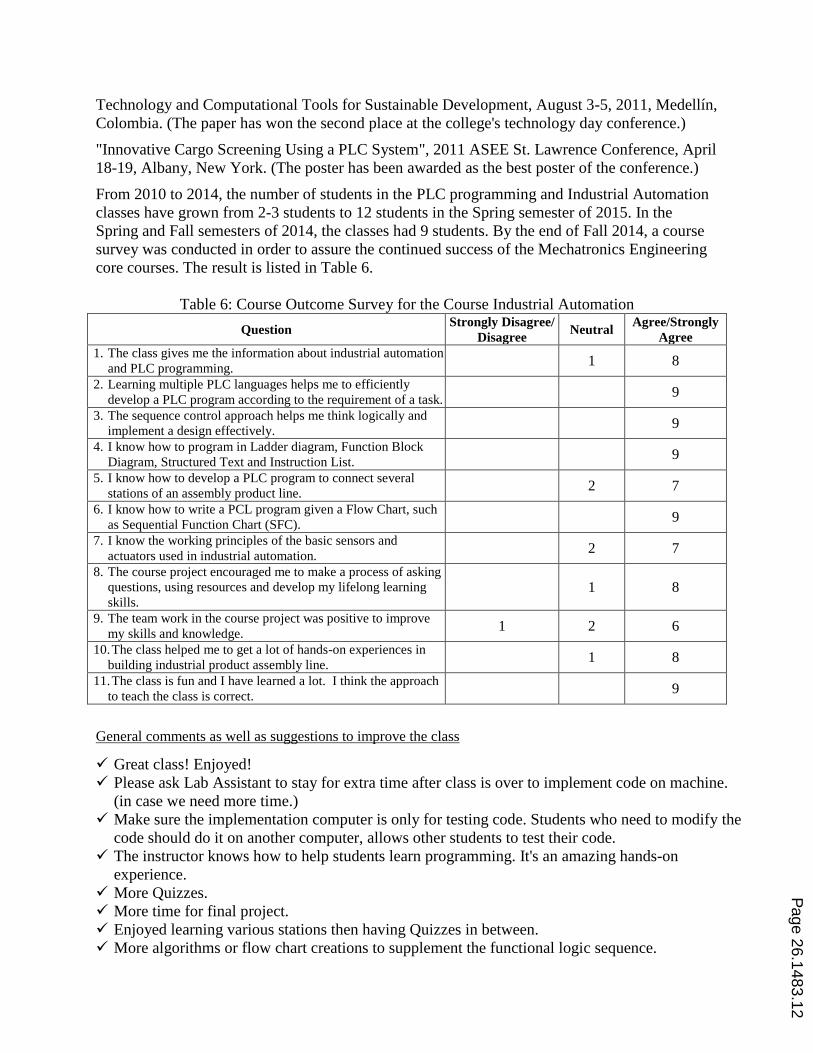
From 2010 to 2014, the number of students in the PLC programming and Industrial Automation
classes have grown from 2-3 students to 12 students in the Spring semester of 2015. In the
Spring and Fall semesters of 2014, the classes had 9 students. By the end of Fall 2014, a course
survey was conducted in order to assure the continued success of the Mechatronics Engineering
core courses. The result is listed in Table 6.
Table 6: Course Outcome Survey for the Course Industrial Automation
Question Strongly Disagree/
Disagree Neutral
Agree/Strongly
Agree
1. The class gives me the information about industrial automation
and PLC programming. 1 8
2. Learning multiple PLC languages helps me to efficiently
develop a PLC program according to the requirement of a task. 9
3. The sequence control approach helps me think logically and
implement a design effectively. 9
4. I know how to program in Ladder diagram, Function Block
Diagram, Structured Text and Instruction List. 9
5. I know how to develop a PLC program to connect several
stations of an assembly product line. 2 7
6. I know how to write a PCL program given a Flow Chart, such
as Sequential Function Chart (SFC). 9
7. I know the working principles of the basic sensors and
actuators used in industrial automation. 2 7
8. The course project encouraged me to make a process of asking
questions, using resources and develop my lifelong learning
skills. 1 8
9. The team work in the course project was positive to improve
my skills and knowledge. 1 2 6
10. The class helped me to get a lot of hands-on experiences in
building industrial product assembly line. 1 8
11. The class is fun and I have learned a lot. I think the approach
to teach the class is correct. 9
General comments as well as suggestions to improve the class
Great class! Enjoyed!
Please ask Lab Assistant to stay for extra time after class is over to implement code on machine.
(in case we need more time.)
Make sure the implementation computer is only for testing code. Students who need to modify the
code should do it on another computer, allows other students to test their code.
The instructor knows how to help students learn programming. It's an amazing hands-on
experience.
More Quizzes.
More time for final project.
Enjoyed learning various stations then having Quizzes in between.
More algorithms or flow chart creations to supplement the functional logic sequence.
Page 26.1483.12
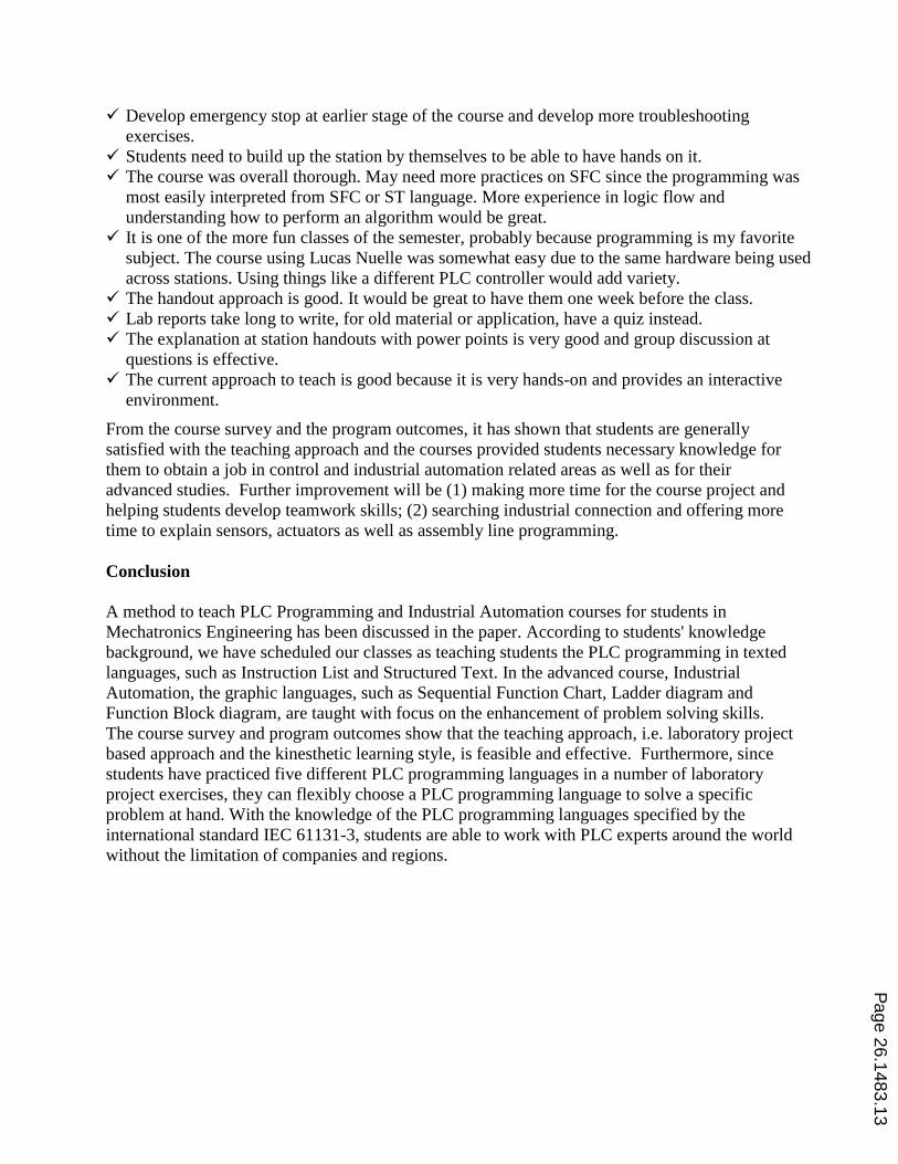
Develop emergency stop at earlier stage of the course and develop more troubleshooting
exercises.
Students need to build up the station by themselves to be able to have hands on it.
The course was overall thorough. May need more practices on SFC since the programming was
most easily interpreted from SFC or ST language. More experience in logic flow and
understanding how to perform an algorithm would be great.
It is one of the more fun classes of the semester, probably because programming is my favorite
subject. The course using Lucas Nuelle was somewhat easy due to the same hardware being used
across stations. Using things like a different PLC controller would add variety.
The handout approach is good. It would be great to have them one week before the class.
Lab reports take long to write, for old material or application, have a quiz instead.
The explanation at station handouts with power points is very good and group discussion at
questions is effective.
The current approach to teach is good because it is very hands-on and provides an interactive
environment.
From the course survey and the program outcomes, it has shown that students are generally
satisfied with the teaching approach and the courses provided students necessary knowledge for
them to obtain a job in control and industrial automation related areas as well as for their
advanced studies. Further improvement will be (1) making more time for the course project and
helping students develop teamwork skills; (2) searching industrial connection and offering more
time to explain sensors, actuators as well as assembly line programming.
Conclusion
A method to teach PLC Programming and Industrial Automation courses for students in
Mechatronics Engineering has been discussed in the paper. According to students' knowledge
background, we have scheduled our classes as teaching students the PLC programming in texted
languages, such as Instruction List and Structured Text. In the advanced course, Industrial
Automation, the graphic languages, such as Sequential Function Chart, Ladder diagram and
Function Block diagram, are taught with focus on the enhancement of problem solving skills.
The course survey and program outcomes show that the teaching approach, i.e. laboratory project
based approach and the kinesthetic learning style, is feasible and effective. Furthermore, since
students have practiced five different PLC programming languages in a number of laboratory
project exercises, they can flexibly choose a PLC programming language to solve a specific
problem at hand. With the knowledge of the PLC programming languages specified by the
international standard IEC 61131-3, students are able to work with PLC experts around the world
without the limitation of companies and regions.
Page 26.1483.13
Bibliography [1] M. R. Lucas and D. M. Tilbury, Comparing industrial logic design methods used in the automotive industry.
IEEE Conf. on System, Man, and Cybernetics, 2003, pp. 530-537.
[2] P. Burkimsher and H. Milcent, Applying industrial solutions to the control of HEP experiments. Proc. of Int.
Conf. on Accelerator and Large Experimental Physics Control Systems, Trieste, Italy, 1999, pp. 362-364.
[3] A. Ozkan and K. Çetinkaya, Process automation and mixture filling system design. J. of Engineering Research
and Applied Science, 1(2), 2012, pp. 98-106.
[4] M. Gäfvert, T. Skoglund, J. Tummescheit, J. Wikander, J. Windahl and P. Reuterswärd, Real-time HWIL
simulation of liquid food process lines. Proc. of 6th
Int. Modelica Conf., 2008, pp.709-715, Modelica
Association.
[5] H. Jack, Automating Manufacturing Systems with PLCs, Lulu Press, Inc, 2010.
[6] W. T. Evans, Programmable Logic Controllers: Fundamentals and Applications, Spiral, 2005.
[7] J. A. Rehg, "Structured PLC programming with sequential function charts", The 2001 ASEE Annual
Conference & Exposition, Albuquerque, New Mexico, June 2001.
[8] Lucas Nueller Ltd, http://www.lucas-nuelle.us/2757/apg/1425/Products/UniTrain-I.htm, accessed by Jan. 2015.
[9] Lucas Nueller Ltd, http://www.lucas-nuelle.us/2768/apg/3484/Mechatronics-Sub-Systems-with-Siemens-
PLC.htm, accessed by Jan. 2015.
Page 26.1483.14