teams - · pdf filemicroscope (om) 1 50 - 1 µm yes yes ... function apply ice layer to...
TRANSCRIPT


TeamsTeam Personnel
1. Team leader and system engineer Marine
2. Science Jonas, Esmee, Julia, Victoria
2. Payload John, Adrian, Gwenael
3. Platform Marine, Adrian, Fabio, Lisa, Marta
4. Mission analysis Mattia, Andre, Jophiel
3

Contents
1. Science case2. Payload concept3. Mission profile4. Platform5. Mission design6. Conclusion
4

Contents
1. Science case2. Payload concept3. Mission profile4. Platform5. Mission design6. Conclusion
5

Contents
1. Science case2. Payload concept3. Mission profile4. Platform5. Mission design6. Conclusion
6

Contents
1. Science case2. Payload concept3. Mission profile4. Platform5. Mission design6. Conclusion
7

Contents
1. Science case2. Payload concept3. Mission profile4. Platform5. Mission design6. Conclusion
8
Contents
1. Science case2. Payload concept3. Mission profile4. Platform5. Mission design6. Conclusion
9

Science case

Investigating the physics of grain growth Why study dust growth?● Planets● Gaps in knowledge
○ Models○ 30 µm - 100 µm○ Low velocity interaction
Why a laboratory in space?● Remote observations cannot
resolve interactions● Need:
○ Low relative velocities○ Long time in micro-gravity○ No big disturbances Zsom et al. 2010
11

Understand the physics of dust growth at low velocities (<5 mm/s) in protoplanetary disks by observing the evolution of
dust size and shape in micro-gravity over long time scales.
Science objective
12
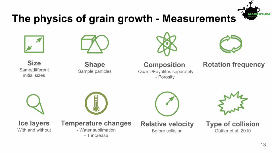
The physics of grain growth - Measurements
Relative velocity Before collision
Size Same/different
initial sizes
Composition - Quartz/Fayalites separately
- Porosity
Type of collision Güttler et al. 2010
Rotation frequency
Ice layers With and without
Shape Sample particles
Temperature changes - Water sublimation
- T increase
13

The physics of grain growth - Environment
● Gas : dust mass ratio = 100 : 1 for µm-sized particles
● Magnetic field: expected to be in the order of ~2.9*10-5 T inside the volume● Temperature: < 230 K inside the volume● Pressure: between 0.1 - 6 mbar inside the volume
14

Initial experimental conditions
15

Payload

Scientific requirement Measurement requirement Rationale
Measure of sizeThe size shall be measured in the range between 1 µm and 1cm with a precision
of 10%.
Analyze how the size of the incoming particles affect the
grain growth.
Measure of relative velocity
The relative velocity of incoming and outgoing particles shall be measured in the range between 1µm/s and 5 mm/s
with a precision of 1%.
Analyze the influence of relative velocity in the grain growth.
Measure of rotational velocity
The rotational velocity of incoming particles shall be measured at 120 fps
(frames per second).
Analyze possible influence of rotation in the particle interaction
and grain growth.
Measurement requirements
17
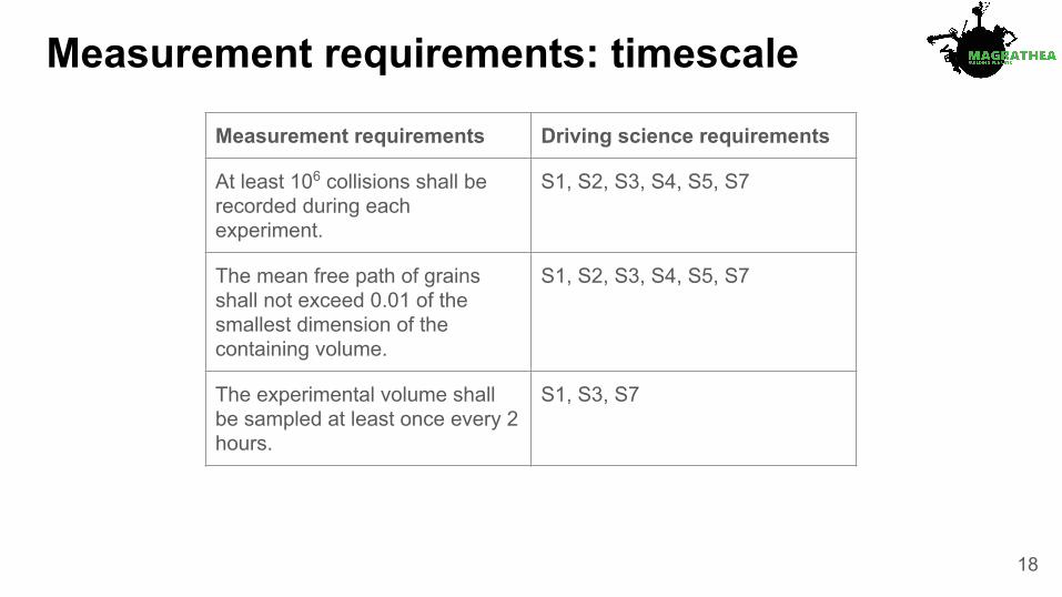
Measurement requirements: timescale
M3: For close-range measurements, the experimental volume shall be sampled at least once per hr.
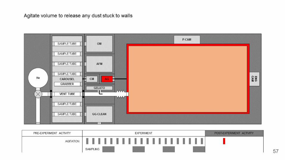
M4: The number of particles stuck to the walls of the experimental volume shall not exceed 20% of the total number of particles in the experimental volume at any time.
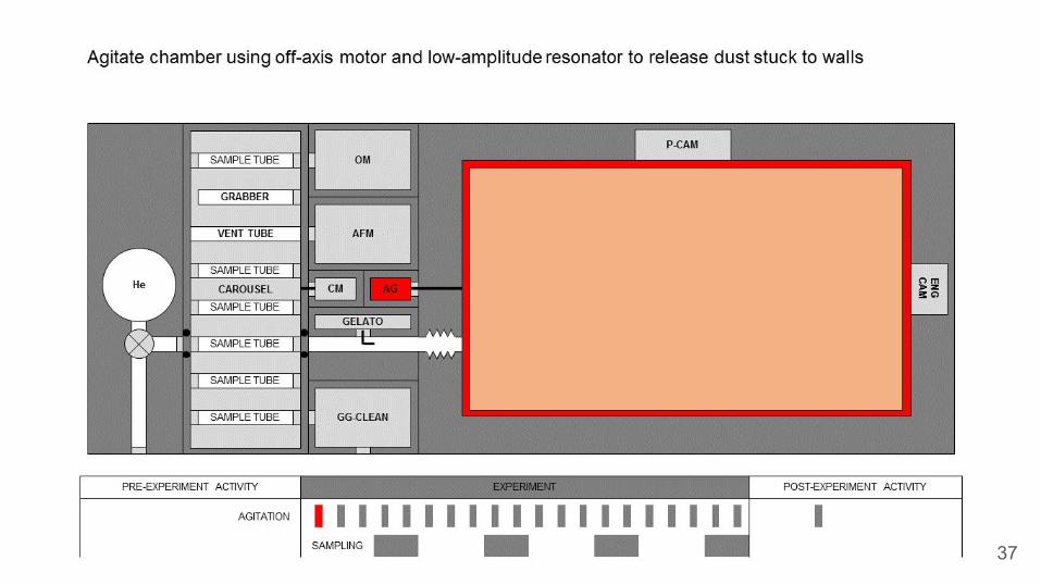
M5: The velocity of particles released from the walls during any agitation manoeuvre shall not exceed 2 mm s-1, measured relative to the wall.
M6: The number of particles in the experimental volume at the start of each experiment shall not exceed 1% of the number of particles at the end of the previous experiment.
Measurement requirements Driving science requirements
At least 106 collisions shall be recorded during each experiment.
S1, S2, S3, S4, S5, S7
The mean free path of grains shall not exceed 0.01 of the smallest dimension of the containing volume.
S1, S2, S3, S4, S5, S7
The experimental volume shall be sampled at least once every 2 hours.
S1, S3, S7
18

Measurement requirements: cleanliness
Measurement requirements Driving science requirements
No more than 20% of particles may be stuck to the walls of the containing volume during any experiment
S1, S2, S3, S4, S5, S7
The speed of particles released from walls after any agitation shall not exceed 2 mm s-1
S1, S2, S3, S4, S5, S7
No more than 1% of particles may remain in the chamber after each experiment
S1, S2, S3, S4, S5, S7
19
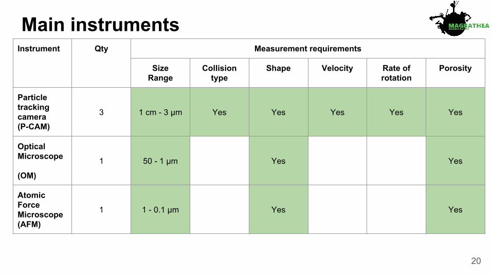
Instrument Qty Measurement requirements
SizeRange
Collision type
Shape Velocity Rate of rotation
Porosity
Particle tracking camera (P-CAM)
3 1 cm - 3 µm Yes Yes Yes Yes Yes
Optical Microscope
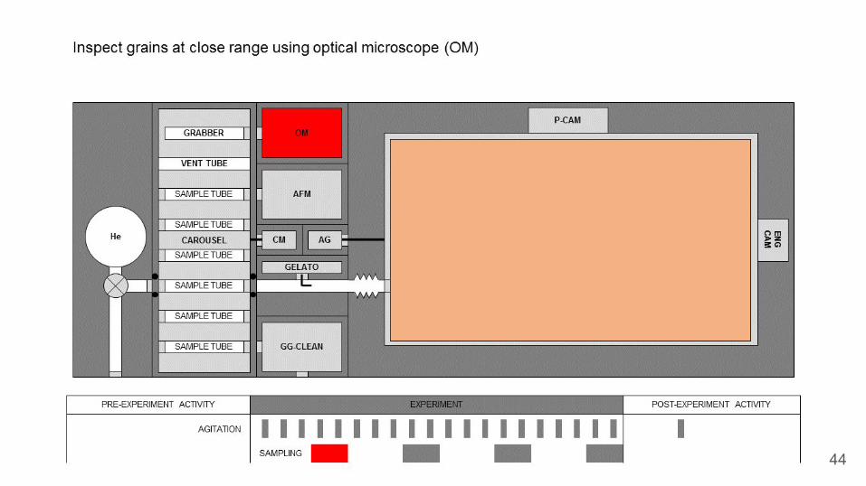
(OM)
1 50 - 1 µm Yes Yes
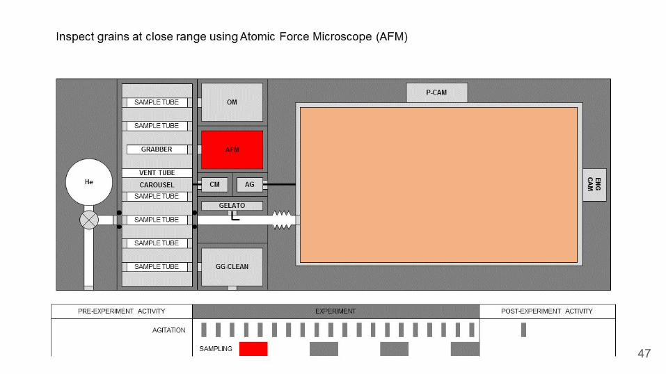
Atomic Force Microscope (AFM)
1 1 - 0.1 µm Yes Yes
Main instruments
20

Measurement principlesParticle tracking Optical microscopy Atomic force microscopy
21

Particle Tracking Camera (P-CAM)
Optical Microscope(OM)
Atomic Force Microscope (AFM)
Heritage: Phoenix (MARDI)Mass: 1.5 kgPower: 4 WData rate: 5.4 Mb s-1
Volume: 70x70x70 mm
Heritage: Rosetta (CIVA-M/V)Mass: 1.1 kgPower: 1 WData rate: 0.075 Mb s-1
Volume: 70x50x91 mm
Heritage: Rosetta (MIDAS)Mass: 8.3 kgPower: 17 WData rate: 0.001 Mb s-1
Volume: 300x250x100 mm
Instrument description
22

PAYLOAD
INSTRUMENTATION
ENVIRONMENTAL MONITORING
FAR RANGE GRAIN MEASUREMENT
CLOSE RANGE GRAIN MEASUREMENT
PRESSURE TRANSDUCER X6
THERMOCOUPLE X6
MAGNETOMETER
PARTICLE TRACKING CAMERA X3
VOLUME MONITOR CAMERA
OPTICAL MICROSCOPE
ATOMIC FORCE MICROSCOPE
SAMPLE HANDLING AND PROCESSING
EXPERIMENTAL VOLUMECAROUSEL
GRAIN INJECTION SYSTEM
PASSIVE COOLING
VOLUME AGITATION SYSTEM
H2O GAS DISPERSAL (GELATO)MASTER VALVE
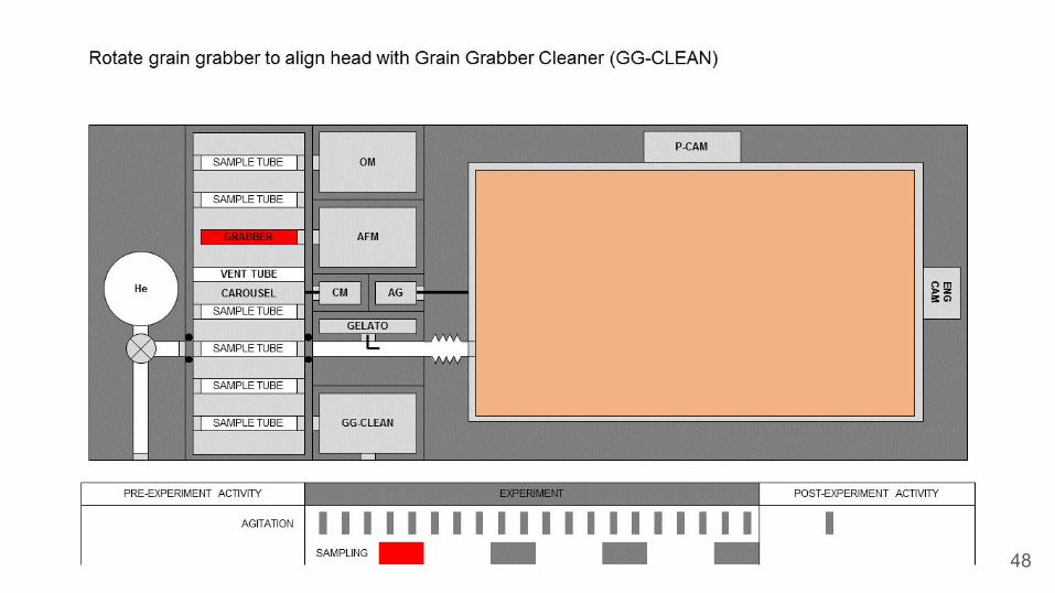
GRAIN RETRIEVAL(GRABBER)
GRAIN EJECTION SYSTEM
Payload breakdown structure
23

Frame
Experimentalvolume
CamerasClose range instruments:-AFM-OM
Suspension
Carousel
Step engine
Agitator
Payload design
GELATO
24

25

26

27

28
29
30
H2O
31
32

33

34

35

36
37

38

39

40

41

42

43
44

45

46
47
48
49

50

51

52

53

54
55

56
57

58
59

60

● The video cameras are working constantly to record the collisions between particles.○ The volume of data is really huge, 41.616 Gb/s○ Problematic to send to Earth, so we need to process it onboard
● Using particle tracking, a program can detect the movement of a particle ○ It is possible then to calculate the linear velocity of incident particles and collisional products.○ This satisfies then the requirement of S4
● Using particle tracking, a program can detect the movement of positions of a particle.○ It is possible then to calculate the size, the inclination of the rotational axis, and the three
rotational velocities around the three angular axes for the incident particles.○ This satisfies then the requirement of S1 and S5
● For particles with an effective radius of 10 micrometer or bigger, we want to see the shape of the incident particles and the shape and collision type of the collisional products. For this, we will send a picture of the particles.
○ This satisfies the requirement of S1, S2 and S3.● Resulting data is expected to be under 17 Mb/s
Data type Maximum data generation rate (Mb s-1)
Raw
Total raw data 42000
After processing
Particle velocities 8
Particle rotation rates 9
Particle images 0.3
Total after processing 17
On-board data processing
61

● Current TRL: 2● Function
○ Collect sample○ Hold samples
● Requirement○ Reusability○ Long stroke
● Solution○ Linear actuator○ Static charger○ Piezo actuator (Curiosity heritage)
● Verification○ Lab testing○ Micro-g for grain adhesionPI Motion Position
SKF
62
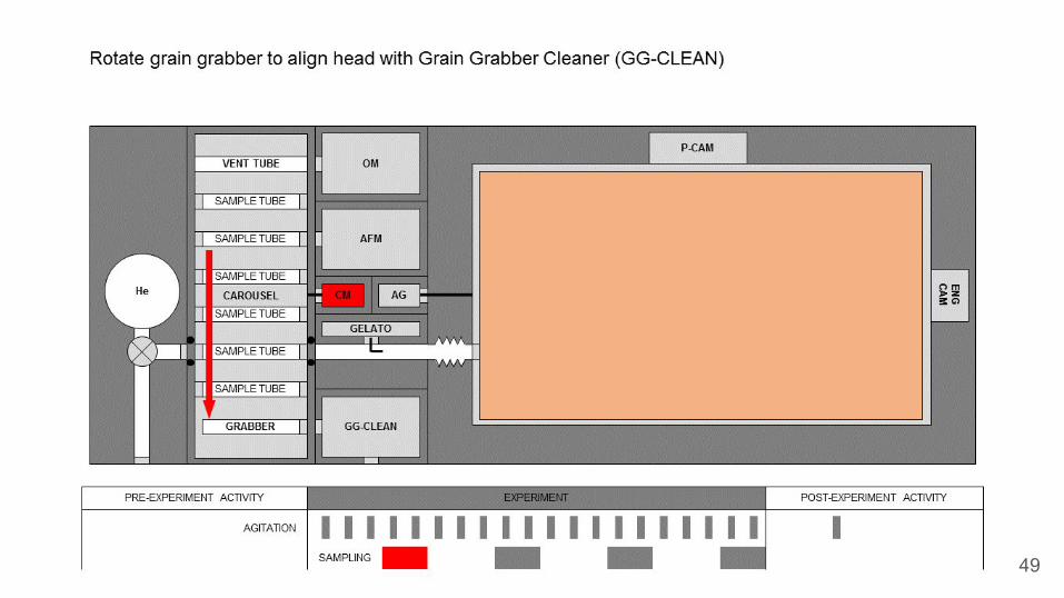
Key technology development plan - Grain Grabber

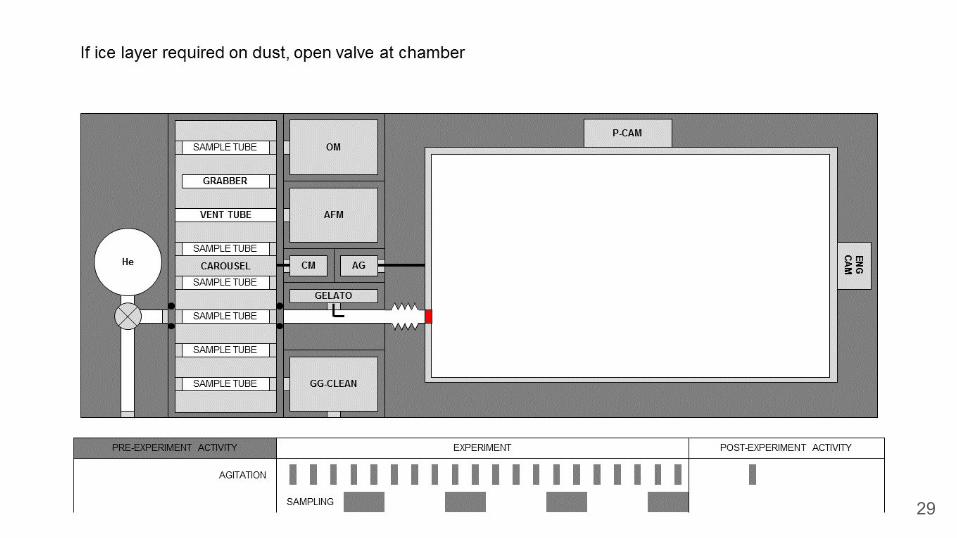
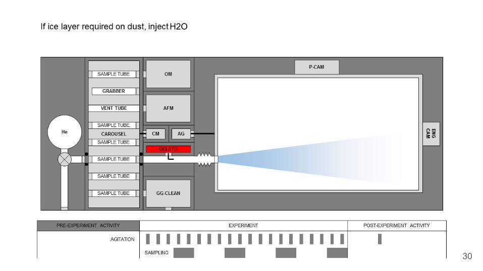
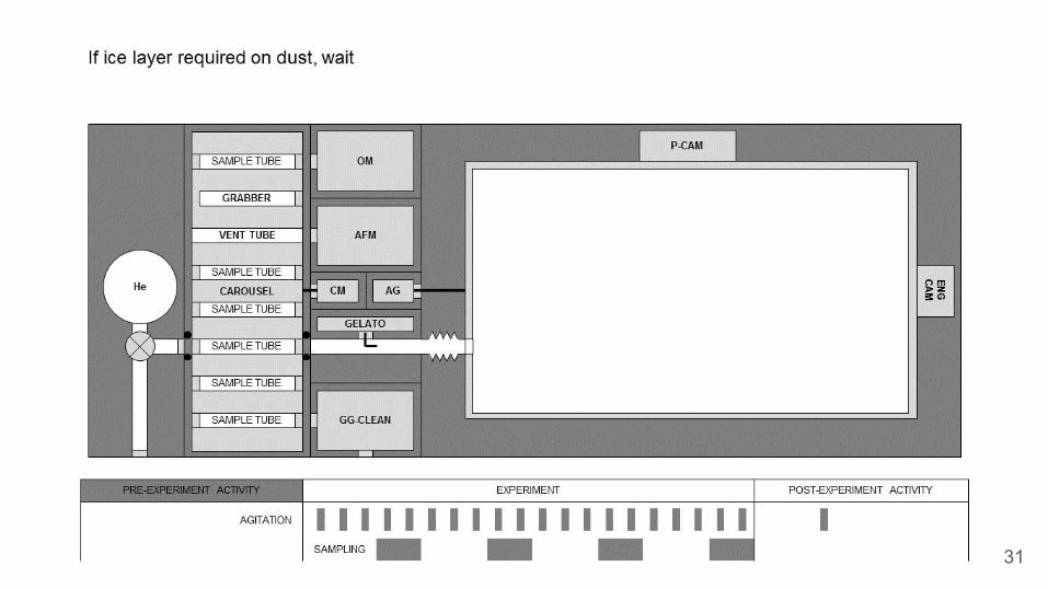
● Current TRL: 2● Function
○ Apply ice layer to dust particles
● Requirement○ Diffuse gaseous H2O
● Solution○ Based on fuel injectors○ Aerosol experiments
● Verification○ Lab testing○ Micro-g for grain adhesion
Key technology development plan - GELATO
63

● Current TRL: 2● Function
○ Hold sample container○ Rotate Grain Grabber
● Requirement○ Hold multiple experiments○ 1m radius
● Solution○ Curiosity SAM module Heritage○ Counter mechanism
Honeybee Robotics
● Testing:○ Eath laboratory○ Micro-G
Key technology development plan - Carousel
64

Mission profile

Objectives, requirements, and driversMission objectives
Achieve all planned science experiments
Downlink and analyse data on the ground
Main system drivers and mission requirements
- Long duration in microgravity- Minimal external disturbances- Thermal control- Data rate
66

Pre-flight● Prepare grain canisters
Transit● Env. conditions on launch
Launch● Soyuz● Sun-Synchronous● 800 km● Mass < 2t● Shared ride possible.
Detumble● Stabilize● Obtain attitude● Deploy comms● Deploy solar
Commissioning● Eliminate rotation● System check● Initiate science
Experiment● Release sample● Take measurements● Vent chamber
Housekeeping● Reorbit● Diagnosis

Launcher and transfer
Launch Vehicle: SoyuzTarget: SSO 800 kmLaunch Base: Guiana Space Center
Orbit Altitude Inclination
Injection 785 ± 12 km 98.6° ± 0.12°
Target 800 km 98.6°
68

OrbitLaunch site: Guyana Space CenterOrbit type: Sun-synchronousAltitude: 800 kmInclination: 98.6°RAAN: 6:00 pm RADN: 6:00am
● Long access times for the downlink● Thermal stability● No attitude corrections to point at
the sun● Acc. from drag & Solar pressure
~10-7 m/s2
69

Delta V BudgetDelta V [m/s] Fuel mass [kg]
Injection 37.85 15.3
Station Keeping
1 Year Mission10 Years
1 Year Mission10 Years
Inclination 5.1 51 1.7 17
Drag 2.4 24 0.8 8
Collision avoidance
0.1 1 0.03 0.3
Deorbit 74.8 31.1
Total 188 71.7
70
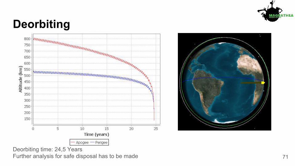
Deorbiting
Deorbiting time: 24,5 YearsFurther analysis for safe disposal has to be made 71

Operations and ground segment● Redu GS - TT&C subsystem - 2.4 m antenna
operating in S-Band
○ 100 kbps up, 2 Mbps down
● Kiruna GS - Scientific data downlink - 15 m antenna operating in X-Band
○ 191.4 GB downloaded per day at 175 Mbps
○ 12 passes per day to download scientific data
○ Each pass consists of 730 seconds (~12 minutes)
72

Platform

Overview of subsystems
74

75
System drivers

1. Solar panels2. Sun shield3. Spacecraft bus4. Payload container5. Louvres for thermal control6. Quartz mirror for thermal control7. Frame8. Ion thrusters for attitude control (x6)9. Hydrazine thrusters (x4)
1
2
36
Spacecraft dimensions:
H: 4400 mmW: 2800 mmL: 2800 mm
Sunshield: ⌀ 5000 mm
4
7
5
8a
8b
9
Spacecraft configuration
76

Spacecraft configuration
77
Spacecraft in stowed arrangement compared with the Soyuz fairing usable volume and a human for scale
Magrathea - concept model

Propulsion subsystem● Functions
○ Orbit injection and correction maneuver○ Detumbling phase○ Station keeping○ Debris avoidance○ End of life maneuver
● Driver○ Safe deorbiting at EOL
● Solution○ 4 x 20 N monopropellant hydrazine○ Isp = 220 s○ DeltaV = 164 m/s
● Technology readiness○ TRL 9
78
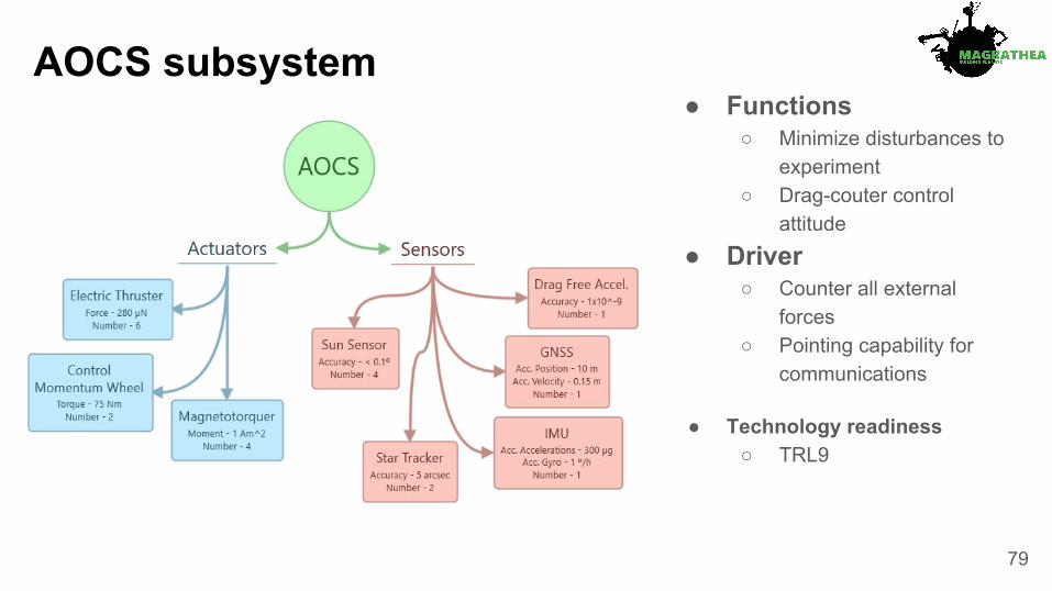
AOCS subsystem● Functions
○ Minimize disturbances to experiment
○ Drag-couter control attitude
● Driver○ Counter all external
forces○ Pointing capability for
communications
● Technology readiness○ TRL9
79

Thermal subsystem● Functions
○ Provide required temperatures for experiment and bus
○ account for IR emission from Earth● Solution
○ MLI○ Sun shield○ Coating○ Louvres○ Heaters○ Optical surface reflector
● Maturity○ TRL9 but high criticality
80
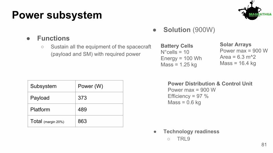
Power subsystem
Subsystem Power (W)
Payload 373
Platform 489
Total (margin 20%) 863
● Solution (900W)
● Technology readiness○ TRL9
● Functions○ Sustain all the equipment of the spacecraft
(payload and SM) with required power
Solar ArraysPower max = 900 WArea = 6.3 m^2Mass = 16.4 kg
Power Distribution & Control UnitPower max = 900 WEfficiency = 97 %Mass = 0.6 kg
Battery CellsN°cells = 10Energy = 100 WhMass = 1.25 kg
81
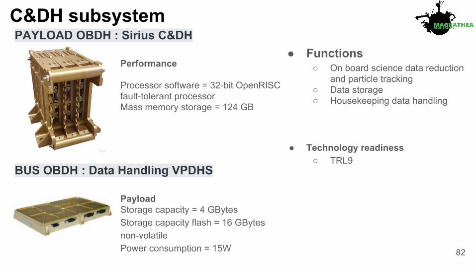
C&DH subsystemPAYLOAD OBDH : Sirius C&DH
BUS OBDH : Data Handling VPDHS
Performance
Processor software = 32-bit OpenRISC fault-tolerant processorMass memory storage = 124 GB
Payload Storage capacity = 4 GBytesStorage capacity flash = 16 GBytes non-volatilePower consumption = 15W
● Functions○ On board science data reduction
and particle tracking○ Data storage○ Housekeeping data handling
● Technology readiness○ TRL9
82
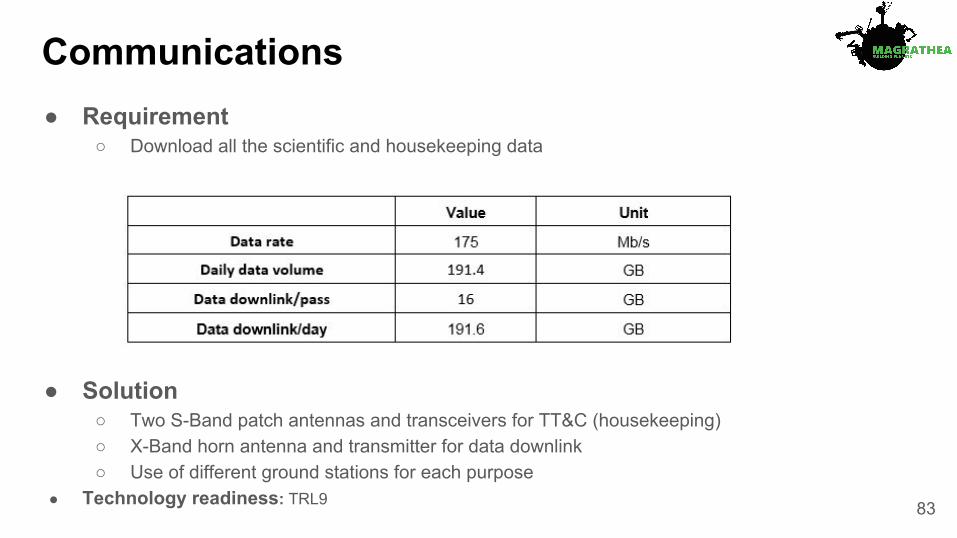
Communications● Requirement
○ Download all the scientific and housekeeping data
● Solution○ Two S-Band patch antennas and transceivers for TT&C (housekeeping)○ X-Band horn antenna and transmitter for data downlink○ Use of different ground stations for each purpose
● Technology readiness: TRL9 83

Main budgetsSubsystem Margin Mass (kg) Power (W)
Payload 35% 289 454
Telecom 20% 23 66
OBDH 20% 3 18
Power 20% 29 27
AOCS 20% 84 266
Propulsion 20% 37 24
Thermal 20% 121 36
Structure 20% 373 0
Propellant 20% 75 0
Total Wet: 1033 891 84
Mission design

Cost Analysis
S/C Bus cost
86

Risk Analysis
R1: Chamber agitationR2: Chamber contaminationR3: Louvre blocking (thermal)R4: Thermal chamber instabilityR5: Solar radiationR6: Debris impactR7: Chamber ventingR8: Water condensationR9: Technology development
(Sample handling andprocessing SS - TRL2)
R10: Wall sticking
87
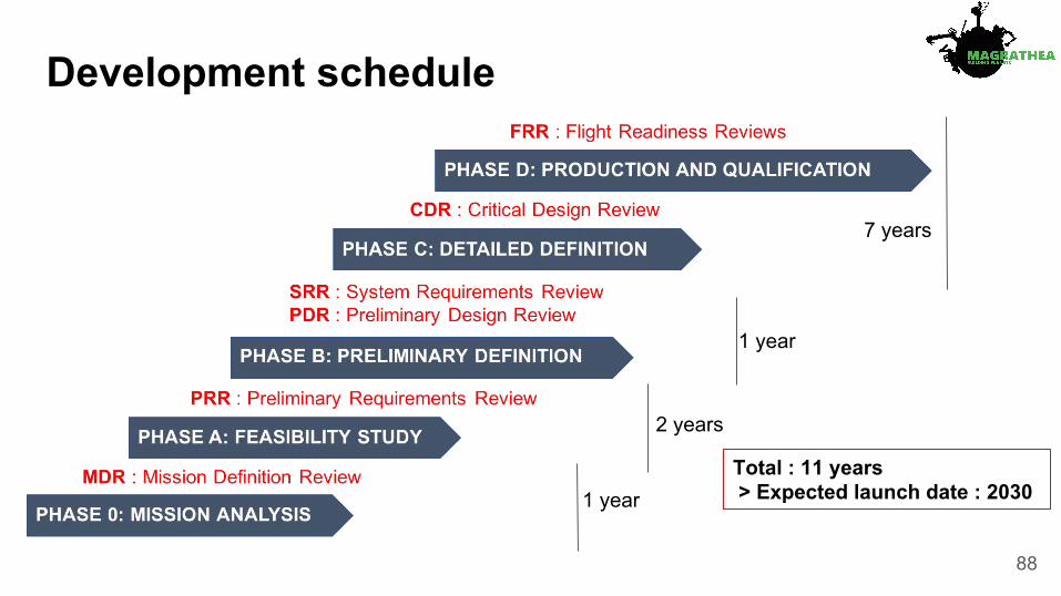
Development schedule
1 year
2 years
1 year
7 years
Total : 11 years > Expected launch date : 2030
88

Descoping options● Reduce number of experiments according to science priority● Remove ice-layer generation capability (GELATO)● Remove Atomic Force Microscope
89

Outreach

Outreach - Middle school
91

Outreach - College
92

Outreach - College
93

Outreach - College
94

Thank you for the Alpbach summer school!
95

96
97
Appendix slides
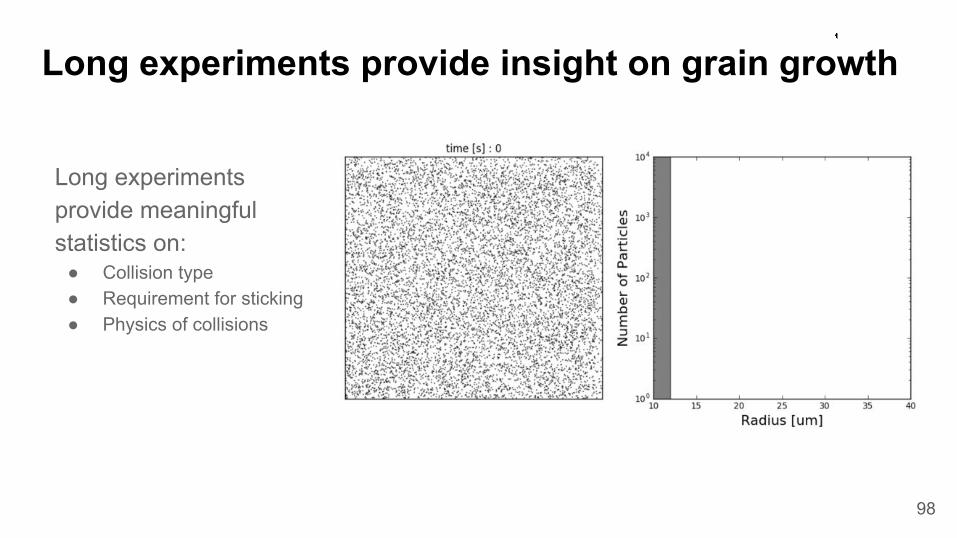
Long experiments provide meaningful statistics on:
● Collision type● Requirement for sticking● Physics of collisions
98
Long experiments provide insight on grain growth

Science requirements Measurement requirements (M1 - M8)
Min. Max. Precision
Understand how the following parameters affect dust grain growth in protoplanetary disks
S1: size (reff) 0.5 µm 1 cm ± 0.1 µm
S2: collision type Classify collision type according to Guttler et al. 2010
S3: shape ± 0.1 µm
S4: rel. velocity 1 µm s-1 5 mm s-1 ± 10 %
S5: rotation rate 0 rev s-1 60 rev s-1 ± 1 %
S6: composition N/A - compositions selected before launch
S7: porosity (φ) 0 1 ± 1 %
S8: ice mantle N/A - icy mantle produced during grain injection
Measurement requirements (old version)
99
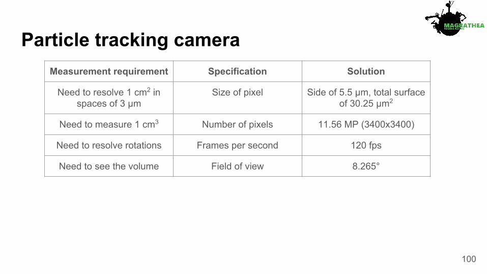
Particle tracking cameraMeasurement requirement Specification Solution
Need to resolve 1 cm2 in spaces of 3 µm
Size of pixel Side of 5.5 µm, total surface of 30.25 µm2
Need to measure 1 cm3 Number of pixels 11.56 MP (3400x3400)
Need to resolve rotations Frames per second 120 fps
Need to see the volume Field of view 8.265°
100

Antennas● TT&C: two S-Band patch antennas and transceivers
● Data downlink: X-Band horn antenna and transmitter
● Gain: 8 dB● Half Power Beam Width (HPBW): 71°● Transmitted power: 20 dBm
● Gain: 10 dB● Half Power Beam Width (HPBW): 55°● Transmitted power: 37.8 dBm
101
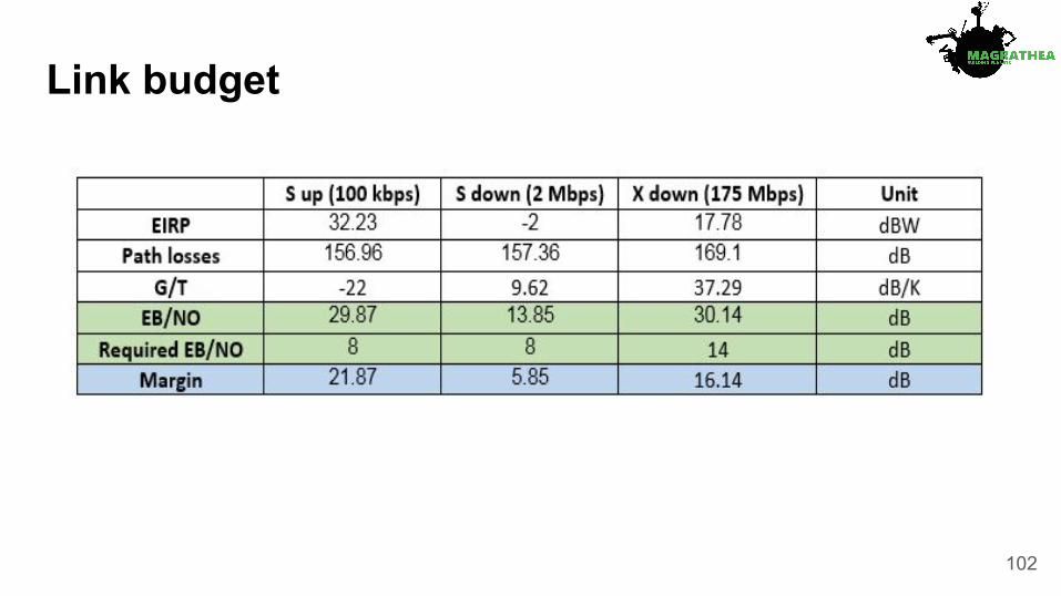
Link budget
102

Thank you tutors!

Thank you tutors!

Thank you tutors!