teamwork & technology
TRANSCRIPT
“TEAMWORK & TECHNOLOGY – A Pre-requisite for Today’s Projects”
“TEAMWORK & TECHNOLOGY – A Pre-requisite for Today’s Projects”
Matt Oakley B.Eng., C.Eng., DIS, MICE.
Project Director - Genesis Structural Systems Sdn Bhd and
Manfred Braun Dipl.-Ing.(FH) Project Director – Köhler+Seitz Beraten und Planen GmbH
SYNOPSIS
The Kuala Lumpur Monorail Project was a pioneer project in many ways with new advances in engineering, construction and management, not just by Malaysian standards, but at an international level also. This paper describes how these new advances were achieved by a fully integrated team including main contractor, designer, specialist subcontractors and suppliers. The close working relationship between these key parties was paramount to the successful development of engineered solutions and their subsequent implementation. Rather than describing the whole of the Monorail construction in general, key topics have been chosen to illustrate the pertinent issues presented. Finally, a case study illustrates further points using experiences encountered whilst completing three very difficult non-typical spans crossing Jalan Mahameru close to the Klang River, which required a 50m main span. The focus will be on the necessity to communicate and coordinate with all parties in order to provide a tailor made engineered solution that would use the latest technology available in the industry. Aspects covered will include planning, integration of buildability, methodology, temporary works and permanent works design; preparing and understanding all the boundary conditions for the design; use of specialist design and analysis software and electronic data transfer between parties; preparation of fully detailed construction drawings; and selection of specialist equipment and materials from suppliers and subcontractors. 1.0 INTRODUCTION
1.1 Teamwork and Technology
Teamwork in construction is not a new concept, but many of its applications to the construction industry are, such as better flow of information, added value to the design, etc. In addition, its use in construction projects is rapidly increasing as its benefits and advantages are becoming more apparent and pervasive.
Page 1 of 25
“TEAMWORK & TECHNOLOGY – A Pre-requisite for Today’s Projects”
Through teamwork and its active involvement of all key parties (e.g. Contractor, Suppliers, Consultants), projects are far more likely to be finished within the budget, on time, and with the least number of conflicts, claims and work defects. With its emphasis on commitment, trust, equity, continual project evaluations, minimized risks, and its mandate for open communication, teamwork solves problems, saves time and money (thus increasing profits), and minimizes headaches. Further, over the past several years, quality management and teamwork have rapidly worked their way into a prominent position for creating and maintaining smooth, profitable construction projects. If the Construction Industry is to strive to improve, create new milestones and become more efficient, it is vital to explore and develop new technologies to assist us. This process is commonplace in many industries such as electronics, manufacturing, petrochemical, pharmaceuticals etc, where it is known as Research and Development (R&D). These industries have huge R&D departments and divisions with large budgets allocated just for the very purpose of improving so that they can offer something better or cheaper than their competitors. However, in the construction industry it is rarely practised since few consultants or contractors are willing to fund or invest in R&D knowing that any commercial advantages gained would be short lived. Few Engineers or Contractors are willing to jeopardise their reputations by attempting something new at the risk of it failing or being unable to complete the project successfully, and instead tend towards proven techniques and materials. Neither Engineers nor Contractors attempt to look towards other fields of engineering outside of their civil engineering domain, to see if other technologies which have already been proven can be used on civil engineering projects. There is much knowledge to be learnt from this type of continuous improvement since it is cost effective and fast. Areas that can be explored should not just be limited to design or equipment and methods, but management skills also. Topics such as project scheduling, budget, safety and quality are all worthy topics for study including their planning, implementation and monitoring.
1.2 The Kuala Lumpur Monorail Project The Kuala Lumpur Monorail (KLM) Project was a pioneer project in many ways with new advances in engineering, construction and management, not just by Malaysian standards, but at an international level also. Although KLM was the first large scale Monorail project in Malaysia, the Monorail technology has been used elsewhere in the world for more than forty years. However, some of the
Page 2 of 25
Photo 1: The first large scale Monorailsystem in Malaysia
“TEAMWORK & TECHNOLOGY – A Pre-requisite for Today’s Projects”
structural design concepts, critical alignment geometry, span arrangements and construction methodology used in KLM can be considered a first anywhere in the world. This paper describes how these new advances were achieved by a fully integrated team including main contractor, designer, specialist subcontractors and suppliers. The close working relationship between these key parties was paramount to the successful development of engineered solutions and their subsequent implementation.
2.0 OVERVIEW OF KLM GUIDEWAY SYSTEM
The KL Monorail’s infrastructure includes 8.6km of elevated dual guideway beams, 11 stations, 5 associated power sub-stations and 1 depot for maintenance and overhaul. The KLM route begins at Jalan Tun Razak and passes through Jalan Pahang, Jalan Tuanku Abdul Rahman, Jalan Sultan Ismail. Jalan Imbi, Jalan Hang Tuah, Jalan Maharajalela, Jalan Sultan Sulaiman, Jalan Tebing, Jalan Tun Sambanthan 5 before terminating at KL Sentral. The Monorail guideway structure is unique in many ways since the structure also forms the running surface for the vehicle, unlike other rail or highway structures, which have additional surfacing, or track laid over the top. This fundamental constraint of the design criteria means that the beams have to be formed to suit the final alignment geometry, including both vertical and horizontal curves, gradients, transition curves and superelevation. The design of the Monorail structure is based on individually precast post-tensioned beams that are erected and stitched together with insitu concrete joints and continuity post-tensioning to form continuous frames of beams consisting of between two and five spans. Given that the alignment of the beams is so variable with multiple span combinations each frame is considered unique, and must be modelled and analysed individually. With more than eighty frames in the 8.6km alignment the design process is extremely time consuming. Generally, spans are around 30m, however due to various obstructions such as junctions, buried utilities and drainage, as well as other structures such as stations and switches, the spans vary between 12m and 44m. The substructure consists of 900mm diameter bored piles in Kenny Hill formation or 300mm diameter micropiles in limestone formation with cast insitu pilecaps and columns. Generally the crossheads are precast and secured to the column with a prestressed bar connection.
Page 3 of 25
“TEAMWORK & TECHNOLOGY – A Pre-requisite for Today’s Projects”
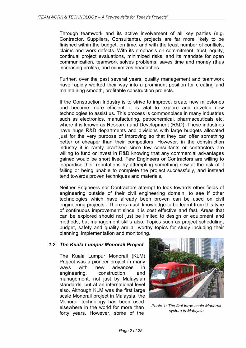
Photo 2: The Sungai Long Precasting Yard was established specifically for casting Guideway
Beams using state of the art technology The beams are precast in a purpose built factory near Sungai Long, from where they are transported to the city using multiaxle transporters ready for their subsequent erection. The lifting and placing of the beams is typically done at night using two telescopic mobile cranes and then held in place by a sophisticated temporary works system which will stabilise the beam and allow beams to be adjusted later to their final position prior to continuity works.
3.0 DESIGN Different contractors submitted their bid for the construction of KL Monorail Guideway Beams. Genesis Structural Systems Sdn Bhd (GSS) teamed up with Köhler+Seitz Beraten und Planen GmbH (K+S) to submit a proposal and establish an estimated construction cost. All existing information, which had been produced by earlier parties, was evaluated/checked and then K+S provided GSS with a guaranteed Bill of Quantities to price. As a result, the bid by GSS was the lowest and GSS was awarded with the Design & Construct package for KL Monorail Guideway Beam. The early creation of a close working relationship between contractor and consultant prior to contract award enabled a competitive proposal to be made. After award of the works to GSS, an agreement between GSS & K+S was finalized and the design works could start. The first step was to study/evaluate the works previously performed by others and to look for areas of improvement as it is always good to learn from the experiences of others. 3.1 Methodology and Buildability,
It is paramount that the construction methodology be thought out at the onset of any project and continuously throughout the duration of the project particularly as new and different situations and locations present themselves. With a wide variety of span combinations and alignment geometry shared with differing topography on site, the methods of construction were required to be flexible enough to suit the stringent requirements of the permanent works design. However, it was also necessary for the permanent works to be tailored to suit the methodology in some cases.
Page 4 of 25
“TEAMWORK & TECHNOLOGY – A Pre-requisite for Today’s Projects”
Buildability is a fashionable word used by both Engineers and Contractors today, both of whom generally disagree when it is used to describe the design for their project which leads to subjective arguments. However, if the Engineer and Contractor are working as one team, together with their specialist subcontractors and suppliers, the methodology can be fully established and understood between them, hence, buildability is no longer a potential topic for conflict, change or delay to the project. The final method to be adopted may be influenced by a number of factors including availability of plant and equipment, traffic management requirements by third parties such local authorities, as well as requirements for custom made items of temporary works equipment.
3.2 Establish Design Criteria
The KLM is very different from many civil engineering projects since there are so many influencing factors on the design. Therefore it is fundamental to establish a full set of design criteria and then document them prior to commencing design activities. These factors include:
a) vehicle loading; b) vehicle rideability; c) other system requirements such as E&M inserts for signalling,
communications and traction power; d) local authority requirements; e) codes of practices and standards; and f) construction methods and operational requirements such as casting
cycle times, transport, lifting and erection systems, prestressing systems and other material specifications.
The preparation of such a design criteria document requires the input from many parties including, client, end users /system supplier, various construction teams as well as perhaps those with previous experience through research and further study.
3.3 Detailed Analysis and Design
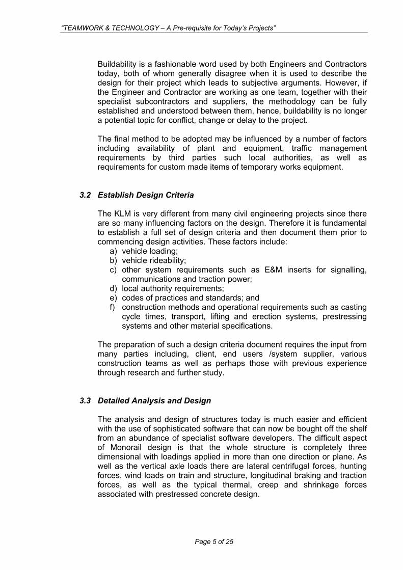
The analysis and design of structures today is much easier and efficient with the use of sophisticated software that can now be bought off the shelf from an abundance of specialist software developers. The difficult aspect of Monorail design is that the whole structure is completely three dimensional with loadings applied in more than one direction or plane. As well as the vertical axle loads there are lateral centrifugal forces, hunting forces, wind loads on train and structure, longitudinal braking and traction forces, as well as the typical thermal, creep and shrinkage forces associated with prestressed concrete design.
Page 5 of 25
“TEAMWORK & TECHNOLOGY – A Pre-requisite for Today’s Projects”
With such an array of loadings to apply to more than eighty unique frames, the selection of a software package(s) which could model all of these criteria together with the soil interaction from the fixed piers within the portal frame type structure, was crucial. The software that was used was called “Sofistik” which allowed all of the forces to be applied to each three dimensional frame model, including an auto loader to simulate the moving train. The software also provided all the necessary details for the prestressing design including post-tensioning forces, losses and expected tendon extensions. The design required a time dependent analysis for the creep and shrinkage effects since the construction method required several stages of prestressing at different phases of the construction, as well as different support conditions during lifting, storage, transportation and placement. The software was able to provide all this and allowed the input for each frame to be entered using various template formats to make the whole analysis process more efficient. The design process would have been considerably more tedious and time consuming if the design team had not decided to invest time and money in new software and consequently new technology.
3.4 Preparation of Detailed Construction Drawings.
It is the conviction of K+S that shop-drawings need to be prepared by the Consultant/Designer since they are in the best position and understanding of critical construction details. Ambiguities, misunderstandings and confusion during the construction execution are eliminated via fully descriptive shop drawings to enhance to overall construction quality. More important, detailed shop-drawings help to avoid cost overruns. One must remember that the majority of the project cost is spent on site. Any design related problems encountered during the construction process are extremely costly and delay the project completion. Further, having many “site-meetings” to discuss technical issues binds resources of top personnel that could be used elsewhere more effectively. While developing difficult details on the drafting board, possible problems can be addressed and counter-measures can be taken already during the design stage. If necessary, due to geometric problems in the reinforcement/prestressing arrangement, a different design approach may have to be taken. This proves to be of no major problem during the design stage but is a major “headache” during the actual construction as it is difficult to make major changes by then.
Page 6 of 25

“TEAMWORK & TECHNOLOGY – A Pre-requisite for Today’s Projects”
K+S prepared for each frame an overview drawing showing the following information:
• Plan layout and elevation • Continuity prestressing detail • Joint details • Bearing schedule • Height levels • Beam weights
Further, K+S prepares for each & every beam reinforcement-drawings showing the following information:
• Reinforcement details • Prestressing tendon profiles • Inserts & cast-in-items for Lifting and E&M System • Bar-bending schedules
In addition to the above, various sequence drawings and standard details are prepared to compliment the reinforcement drawings.
Figure 1: Example of fully detailed construction drawing showing special construction sequence for Frame 68
Page 7 of 25
“TEAMWORK & TECHNOLOGY – A Pre-requisite for Today’s Projects”
4.0 SPECIAL REQUIREMENTS FOR PRECASTING
4.1 Concrete Technology
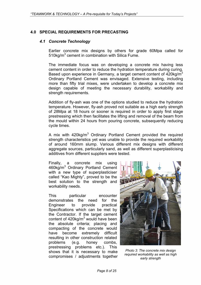
Earlier concrete mix designs by others for grade 60Mpa called for 510kg/m3 cement in combination with Silica Fume. The immediate focus was on developing a concrete mix having less cement content in order to reduce the hydration temperature during curing. Based upon experience in Germany, a target cement content of 420kg/m3 Ordinary Portland Cement was envisaged. Extensive testing, including more than fifty trial mixes, were undertaken to develop a concrete mix design capable of meeting the necessary durability, workability and strength requirements. Addition of fly-ash was one of the options studied to reduce the hydration temperature. However, fly-ash proved not suitable as a high early strength of 28Mpa at 18 hours or sooner is required in order to apply first stage prestressing which then facilitates the lifting and removal of the beam from the mould within 24 hours from pouring concrete, subsequently reducing cycle times. A mix with 420kg/m3 Ordinary Portland Cement provided the required strength characteristics yet was unable to provide the required workability of around 160mm slump. Various different mix designs with different aggregate sources, particularly sand, as well as different superplasticising additives from different suppliers were tested. Finally, a concrete mix using 460kg/m3 Ordinary Portland Cement with a new type of superplasticiser called “Kao Mighty”, proved to be the best solution to the strength and workability needs. This particular encounter demonstrates the need for the Engineer to provide practical Specifications which can be met by the Contractor. If the target cement content of 420kg/m3 would have been the absolute criteria; placing and compacting of the concrete would have become extremely difficult resulting in other construction related problems (e.g. honey combs, prestressing problems etc.). This shows that it is necessary to make compromises / adjustments together r
Page 8 of 25
Photo 3: The concrete mix design equired workability as well as high
early strength
“TEAMWORK & TECHNOLOGY – A Pre-requisite for Today’s Projects”
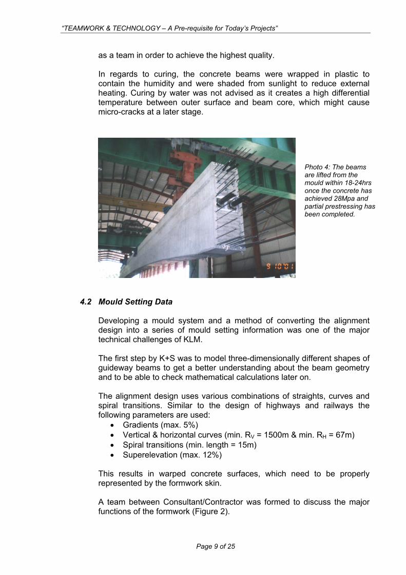
as a team in order to achieve the highest quality. In regards to curing, the concrete beams were wrapped in plastic to contain the humidity and were shaded from sunlight to reduce external heating. Curing by water was not advised as it creates a high differential temperature between outer surface and beam core, which might cause micro-cracks at a later stage.
Photo 4: The beams are lifted from the mould within 18-24hrs once the concrete has achieved 28Mpa apartial prestressing has been completed.
nd
4.2 Mould Setting Data Developing a mould system and a method of converting the alignment design into a series of mould setting information was one of the major technical challenges of KLM. The first step by K+S was to model three-dimensionally different shapes of guideway beams to get a better understanding about the beam geometry and to be able to check mathematical calculations later on. The alignment design uses various combinations of straights, curves and spiral transitions. Similar to the design of highways and railways the following parameters are used:
• Gradients (max. 5%) • Vertical & horizontal curves (min. RV = 1500m & min. RH = 67m) • Spiral transitions (min. length = 15m) • Superelevation (max. 12%)
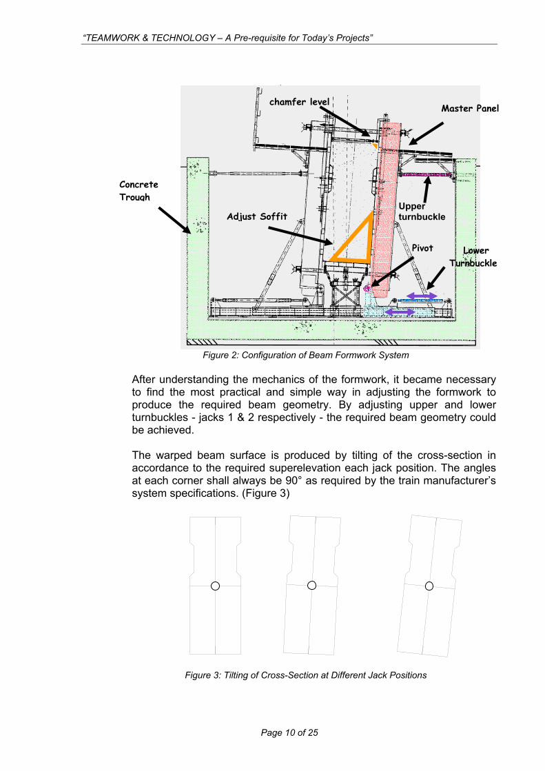
This results in warped concrete surfaces, which need to be properly represented by the formwork skin. A team between Consultant/Contractor was formed to discuss the major functions of the formwork (Figure 2).
Page 9 of 25
“TEAMWORK & TECHNOLOGY – A Pre-requisite for Today’s Projects”
fter understanding the mechanics of the formwork, it became necessary
he warped beam surface is produced by tilting of the cross-section in
Figure 3: Tilting of Cross-Section at Different Jack Positions
Adjust top
Figure 2: Configuration of Beam Formwork System
Adjust Soffit
l
Concrete
Master Panel
Upper
Pivot Lower
chamfer leve
Trough
turnbuckle
Turnbuckle
Ato find the most practical and simple way in adjusting the formwork to produce the required beam geometry. By adjusting upper and lower turnbuckles - jacks 1 & 2 respectively - the required beam geometry could be achieved. Taccordance to the required superelevation each jack position. The angles at each corner shall always be 90° as required by the train manufacturer’s system specifications. (Figure 3)
Page 10 of 25
“TEAMWORK & TECHNOLOGY – A Pre-requisite for Today’s Projects”
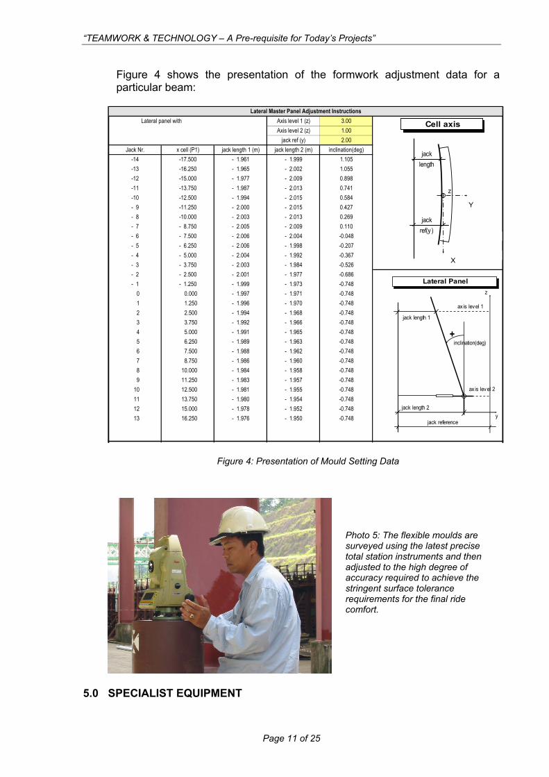
igure 4 shows the presentation of the formwork adjustment data for a
Figure 4: Presentation of Mould Setting Data
5.0 SPECIALIST EQUIPMENT
Fparticular beam:
Cell axis
z
A
jack length
jackref(y )
Y
X
Lateral Panelz
y
ax is level 1
jack reference
+inclination(deg)
jack length 2
jack length 1
ax is level 2
Photo 5: The flexible moulds are
e
de
surveyed using the latest precisetotal station instruments and thenadjusted to the high degree of accuracy required to achieve thstringent surface tolerance requirements for the final ricomfort.
Axis level 1 (z) 3.00Axis level 2 (z) 1.00
jack ref (y) 2.00Jack Nr. x cell (P1) jack length 1 (m) jack length 2 (m) inclination(deg)
-14 -17.500 - 1.961 - 1.999 1.105-13 -16.250 - 1.965 - 2.002 1.055-12 -15.000 - 1.977 - 2.009 0.898-11 -13.750 - 1.987 - 2.013 0.741-10 -12.500 - 1.994 - 2.015 0.584- 9 -11.250 - 2.000 - 2.015 0.427- 8 -10.000 - 2.003 - 2.013 0.269- 7 - 8.750 - 2.005 - 2.009 0.110- 6 - 7.500 - 2.006 - 2.004 -0.048- 5 - 6.250 - 2.006 - 1.998 -0.207- 4 - 5.000 - 2.004 - 1.992 -0.367- 3 - 3.750 - 2.003 - 1.984 -0.526- 2 - 2.500 - 2.001 - 1.977 -0.686- 1 - 1.250 - 1.999 - 1.973 -0.748
0 0.000 - 1.997 - 1.971 -0.7481 1.250 - 1.996 - 1.970 -0.7482 2.500 - 1.994 - 1.968 -0.7483 3.750 - 1.992 - 1.966 -0.7484 5.000 - 1.991 - 1.965 -0.7485 6.250 - 1.989 - 1.963 -0.7486 7.500 - 1.988 - 1.962 -0.7487 8.750 - 1.986 - 1.960 -0.7488 10.000 - 1.984 - 1.958 -0.7489 11.250 - 1.983 - 1.957 -0.748
10 12.500 - 1.981 - 1.955 -0.74811 13.750 - 1.980 - 1.954 -0.74812 15.000 - 1.978 - 1.952 -0.74813 16.250 - 1.976 - 1.950 -0.748
Lateral panel withLateral Master Panel Adjustment Instructions
Page 11 of 25
“TEAMWORK & TECHNOLOGY – A Pre-requisite for Today’s Projects”
he beam transport, lifting, stabilising and adjustment methods for this project
he curvature of the beams presents the obvious problem of managing a
.1 Lifting Beams from Mould
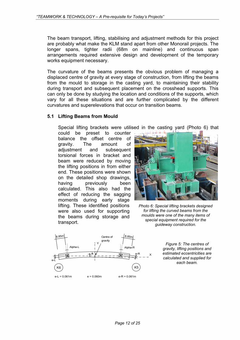
Special lifting brackets were utilised in the casting yard (Photo 6) that
Tare probably what make the KLM stand apart from other Monorail projects. The longer spans, tighter radii (68m on mainline) and continuous span arrangements required extensive design and development of the temporary works equipment necessary. Tdisplaced centre of gravity at every stage of construction, from lifting the beams from the mould to storage in the casting yard, to maintaining their stability during transport and subsequent placement on the crosshead supports. This can only be done by studying the location and conditions of the supports, which vary for all these situations and are further complicated by the different curvatures and superelevations that occur on transition beams. 5
could be preset to counter balance the offset centre of gravity. The amount of adjustment and subsequent torsional forces in bracket and beam were reduced by moving the lifting positions in from either end. These positions were shown on the detailed shop drawings, having previously been calculated. This also had the effect of reducing the sagging moments during early stage lifting. These identified positions were also used for supporting the beams during storage and transport.
.85m
Xe e-R
e-L
Alpha-RAlpha-L
K6 K5
e-L = 0.061m e-R = 0.061me = 0.060m
8.85m8 Centre of gravity
Y
Photo 6: Special lifting brackets designed for lifting the curved beams from the
moulds were one of the many items of special equipment required for the
guideway construction.
Figure 5: The centres of gravity, lifting positions and e stimated eccentricities arecalculated and supplied for
each beam.
Page 12 of 25
“TEAMWORK & TECHNOLOGY – A Pre-requisite for Today’s Projects”
5.2 Beam Transport
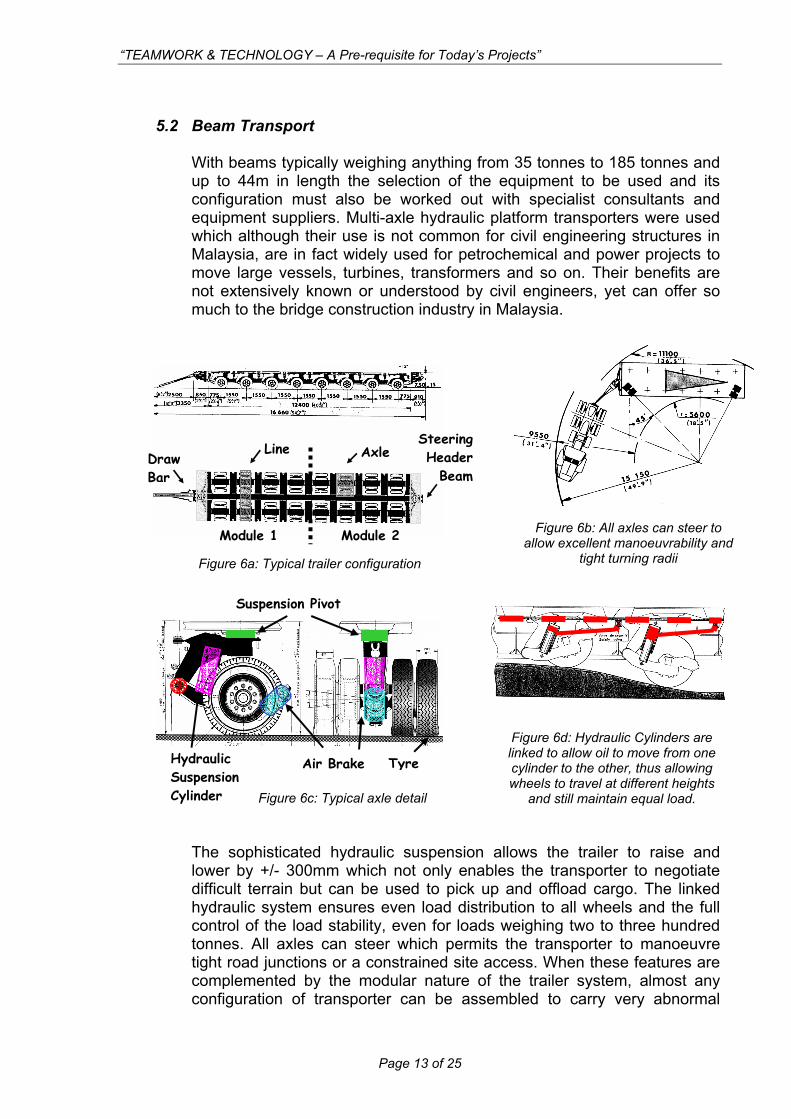
With beams typically weighing anything from 35 tonnes to 185 tonnes and up to 44m in length the selection of the equipment to be used and its configuration must also be worked out with specialist consultants and equipment suppliers. Multi-axle hydraulic platform transporters were used which although their use is not common for civil engineering structures in Malaysia, are in fact widely used for petrochemical and power projects to move large vessels, turbines, transformers and so on. Their benefits are not extensively known or understood by civil engineers, yet can offer so much to the bridge construction industry in Malaysia.
tight turning radii
Figure 6c: Typical axle detail
Figure 6b: All axles can steer to allow excellent manoeuvrability and
Figure 6a: Typical trailer configuration
Steering Header
Beam Draw Bar
Module 1 Module 2
Axle Line
Tyre Air Brake
Suspension Pivot
Hydraulic Suspension Cylinder
Figure 6d: Hydraulic Cylinders are linked to allow oil to move from one cylinder to the other, thus allowing wheels to travel at different heights
and still maintain equal load.
The sophisticated hydraulic suspension allows the trailer to raise and lower by +/- 300mm which not only enables the transporter to negotiate difficult terrain but can be used to pick up and offload cargo. The linked hydraulic system ensures even load distribution to all wheels and the full control of the load stability, even for loads weighing two to three hundred tonnes. All axles can steer which permits the transporter to manoeuvre tight road junctions or a constrained site access. When these features are complemented by the modular nature of the trailer system, almost any configuration of transporter can be assembled to carry very abnormal
Page 13 of 25
“TEAMWORK & TECHNOLOGY – A Pre-requisite for Today’s Projects”
s over the River Klang.
loads. The transporters used for this project were hauled using heavy duty prime movers equipped with powerful 500bhp engines with torque converters and special gearboxes to give maximum power and control. Figures 5a, b, c and d illustrate some of the basic features of multi-axle transporters. (Self propelled transporters with onboard drive systems, fully computer controlled steering and suspension systems are also available and can be used to pick up and move complete bridges weighing thousands of tonnes.) The design of the interface between the beam and transporter is crucial since it must accommodate the variable geometry, restraining forces required to stabilise the beam, together with the dynamic movements of the transporter as it negotiates the bends, gradients and junctions along the route from Sungai Long to the city. It was imperative to design an interface that would not only transmit the huge loads into the transporter correctly and safely but also had to ensure that dynamic forces transmitted back into the beam were controlled and considered by the beam designer. This critical interface was developed through team effort between specialist consultant, specialist transport equipment supplier and permanent works engineer and resulted in the design and fabrication of a set of “smart” bolsters and brackets that could be used for any type of guideway beam.
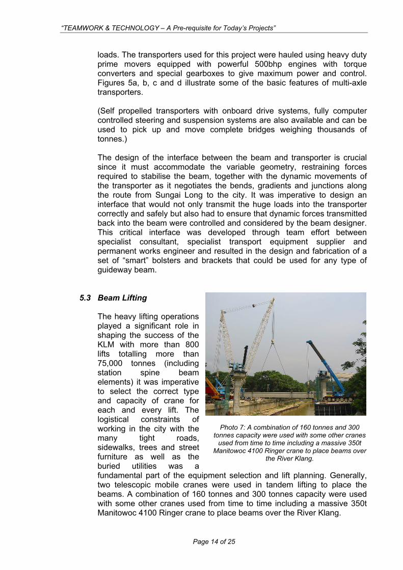
5.3 Beam Lifting The heavy lifting operations played a significant role in shaping the success of the KLM with more than 800 lifts totalling more than 75,000 tonnes (including station spine beam elements) it was imperative to select the correct type and capacity of crane for each and every lift. The logistical constraints of working in the city with the many tight roads, sidewalks, trees and street furniture as well as the buried utilities was a fundamental part of the equipment selection and lift planning. Generally, two telescopic mobile cranes were used in tandem lifting to place the beams. A combination of 160 tonnes and 300 tonnes capacity were used with some other cranes used from time to time including a massive 350t Manitowoc 4100 Ringer crane to place beam
Photo 7: A combination of 160 tonnes and 300 onnes capacity were used with some other cranes used from time to time including a massive 350t anitowoc 4100 Ringer crane to place beams over
t
Mthe River Klang.
Page 14 of 25
“TEAMWORK & TECHNOLOGY – A Pre-requisite for Today’s Projects”
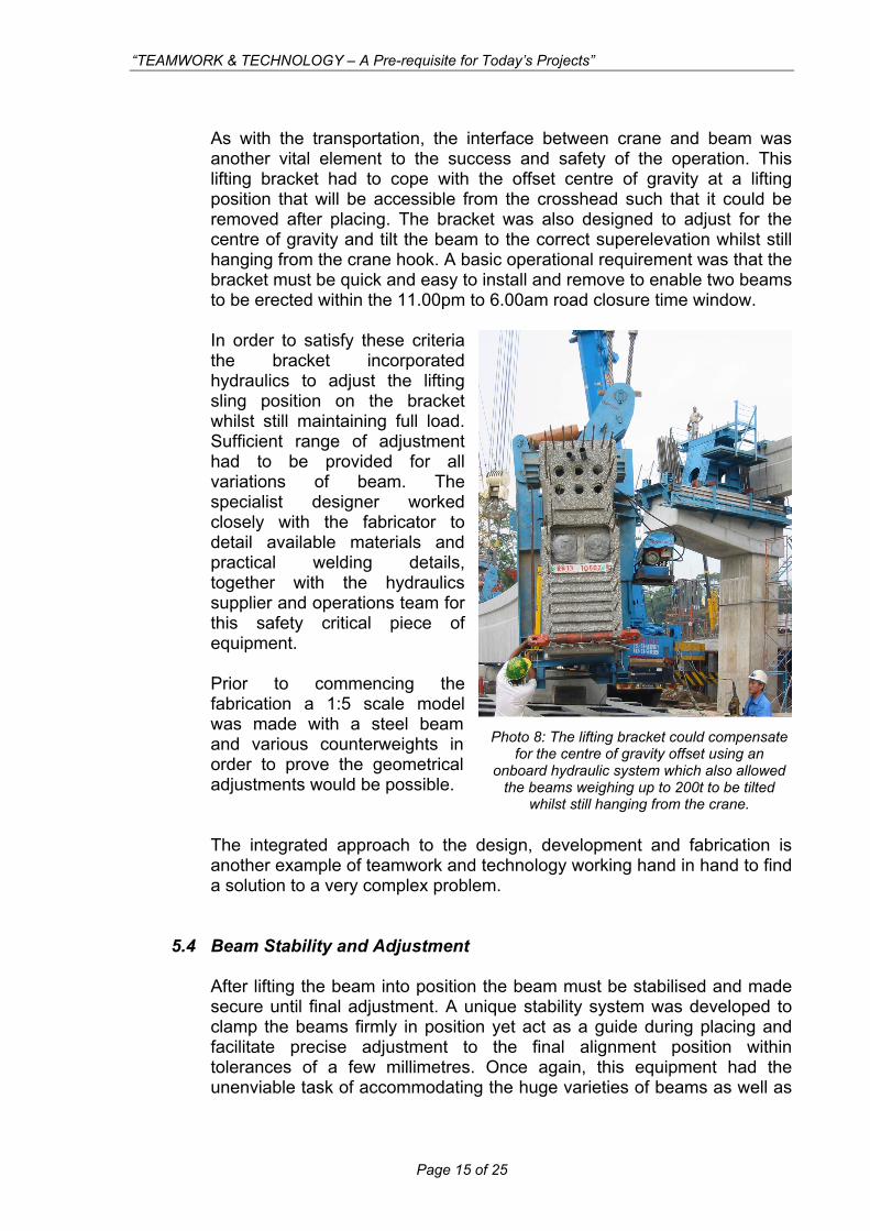
As with the transportation, the interface between crane and beam was another vital element to the success and safety of the operation. This lifting bracket had to cope with the offset centre of gravity at a lifting position that will be accessible from the crosshead such that it could be removed after placing. The bracket was also designed to adjust for the centre of gravity and tilt the beam to the correct superelevation whilst still hanging from the crane hook. A basic operational requirement was that the bracket must be quick and easy to install and remove to enable two beams to be erected within the 11.00pm to 6.00am road closure time window. In order to satisfy these criteria the bracket incorporated hydraulics to adjust the lifting sling position on the bracket whilst still maintaining full load. Sufficient range of adjustment had to be provided for all variations of beam. The specialist designer worked closely with the fabricator to detail available materials and practical welding details, together with the hydraulics supplier and operations team for this safety critical piece of equipment. Prior to commencing the fabrication a 1:5 scale model was made with a steel beam and various counterweights in order to prove the geometrical adjustments would be possible. The integrated approach to the design, development and fabrication is another example of teamwork and technology working hand in hand to find a solution to a very complex problem.
Photo 8: The lifting bracket could compensate for the centre of gravity offset using an
onboard hydraulic system which also allowed the beams weighing up to 200t to be tilted
t still hanging from the crawhils ne.
5.4 Beam Stability and Adjustment After lifting the beam into position the beam must be stabilised and made secure until final adjustment. A unique stability system was developed to clamp the beams firmly in position yet act as a guide during placing and facilitate precise adjustment to the final alignment position within tolerances of a few millimetres. Once again, this equipment had the unenviable task of accommodating the huge varieties of beams as well as
Page 15 of 25
“TEAMWORK & TECHNOLOGY – A Pre-requisite for Today’s Projects”
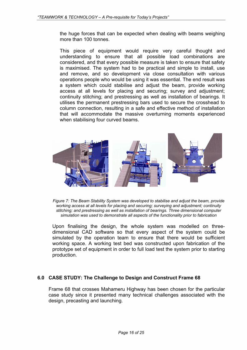
the huge forces that can be expected when dealing with beams weighing more than 100 tonnes. This piece of equipment would require very careful thought and understanding to ensure that all possible load combinations are considered, and that every possible measure is taken to ensure that safety is maximised. The system had to be practical and simple to install, use and remove, and so development via close consultation with various operations people who would be using it was essential. The end result was a system which could stabilise and adjust the beam, provide working access at all levels for placing and securing; survey and adjustment; continuity stitching; and prestressing as well as installation of bearings. It utilises the permanent prestressing bars used to secure the crosshead to column connection, resulting in a safe and effective method of installation that will accommodate the massive overturning moments experienced when stabilising four curved beams.
Figure 7: The Beam Stability System was developed to stabilise and adjust the beam, provide
working access at all levels for placing and securing; surveying and adjustment; continuity stitching; and prestressing as well as installation of bearings. Three dimensional computer
simulation was used to demonstrate all aspects of the functionality prior to fabrication Upon finalising the design, the whole system was modelled on three-dimensional CAD software so that every aspect of the system could be simulated by the operation team to ensure that there would be sufficient working space. A working test bed was constructed upon fabrication of the prototype set of equipment in order to full load test the system prior to starting production.
6.0 CASE STUDY: The Challenge to Design and Construct Frame 68
Frame 68 that crosses Mahameru Highway has been chosen for the particular case study since it presented many technical challenges associated with the design, precasting and launching.
Page 16 of 25
“TEAMWORK & TECHNOLOGY – A Pre-requisite for Today’s Projects”
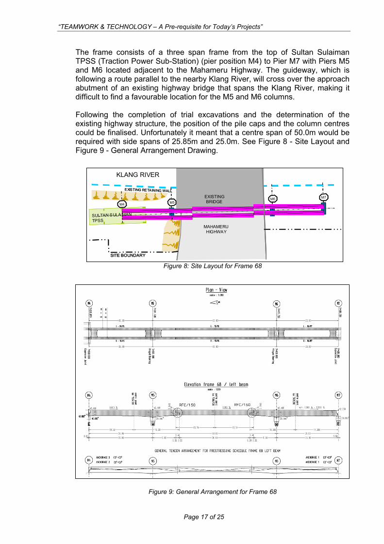
The frame consists of a three span frame from the top of Sultan Sulaiman TPSS (Traction Power Sub-Station) (pier position M4) to Pier M7 with Piers M5 and M6 located adjacent to the Mahameru Highway. The guideway, which is following a route parallel to the nearby Klang River, will cross over the approach abutment of an existing highway bridge that spans the Klang River, making it difficult to find a favourable location for the M5 and M6 columns. Following the completion of trial excavations and the determination of the existing highway structure, the position of the pile caps and the column centres could be finalised. Unfortunately it meant that a centre span of 50.0m would be required with side spans of 25.85m and 25.0m. See Figure 8 - Site Layout and Figure 9 - General Arrangement Drawing.
Figure 8: Site Layout for Frame 68
KLANG RIVER
MAHAMERU HIGHWAY
EXISTING BRIDGE
M4 M5
EXISTING RETAINING WALL
SULTAN SULAIMAN TPSS
SITE BOUNDARY
M6 M7
KLANG RIVER
MAHAMERU HIGHWAY
EXISTING BRIDGE
M4 M5
EXISTING RETAINING WALL
SULTAN SULAIMAN TPSS
SITE BOUNDARY
M6 M7
Figure 9: General Arrangement for Frame 68
Page 17 of 25
“TEAMWORK & TECHNOLOGY – A Pre-requisite for Today’s Projects”
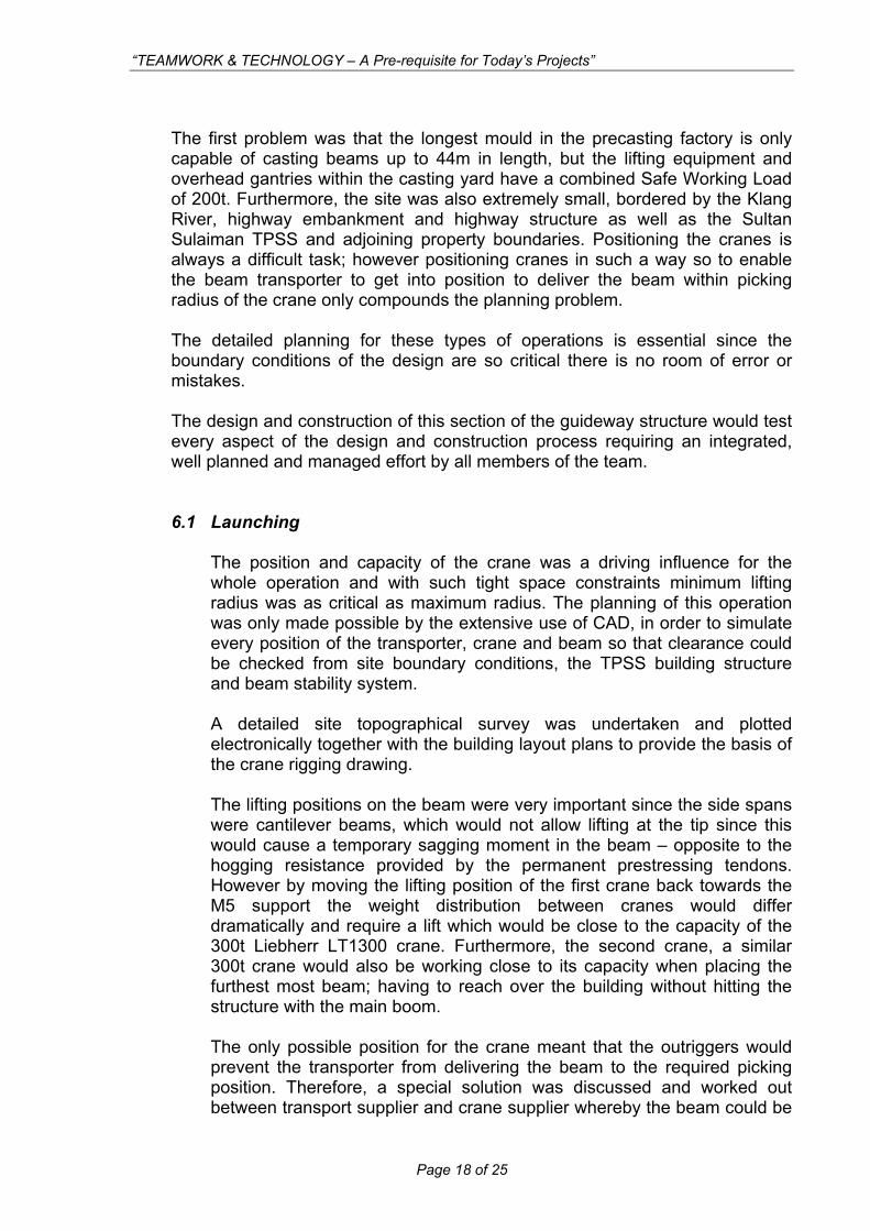
The first problem was that the longest mould in the precasting factory is only capable of casting beams up to 44m in length, but the lifting equipment and overhead gantries within the casting yard have a combined Safe Working Load of 200t. Furthermore, the site was also extremely small, bordered by the Klang River, highway embankment and highway structure as well as the Sultan Sulaiman TPSS and adjoining property boundaries. Positioning the cranes is always a difficult task; however positioning cranes in such a way so to enable the beam transporter to get into position to deliver the beam within picking radius of the crane only compounds the planning problem. The detailed planning for these types of operations is essential since the boundary conditions of the design are so critical there is no room of error or mistakes. The design and construction of this section of the guideway structure would test every aspect of the design and construction process requiring an integrated, well planned and managed effort by all members of the team.
6.1 Launching
The position and capacity of the crane was a driving influence for the whole operation and with such tight space constraints minimum lifting radius was as critical as maximum radius. The planning of this operation was only made possible by the extensive use of CAD, in order to simulate every position of the transporter, crane and beam so that clearance could be checked from site boundary conditions, the TPSS building structure and beam stability system. A detailed site topographical survey was undertaken and plotted electronically together with the building layout plans to provide the basis of the crane rigging drawing. The lifting positions on the beam were very important since the side spans were cantilever beams, which would not allow lifting at the tip since this would cause a temporary sagging moment in the beam – opposite to the hogging resistance provided by the permanent prestressing tendons. However by moving the lifting position of the first crane back towards the M5 support the weight distribution between cranes would differ dramatically and require a lift which would be close to the capacity of the 300t Liebherr LT1300 crane. Furthermore, the second crane, a similar 300t crane would also be working close to its capacity when placing the furthest most beam; having to reach over the building without hitting the structure with the main boom. The only possible position for the crane meant that the outriggers would prevent the transporter from delivering the beam to the required picking position. Therefore, a special solution was discussed and worked out between transport supplier and crane supplier whereby the beam could be
Page 18 of 25
“TEAMWORK & TECHNOLOGY – A Pre-requisite for Today’s Projects”
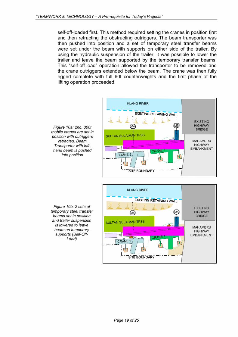
self-off-loaded first. This method required setting the cranes in position first and then retracting the obstructing outriggers. The beam transporter was then pushed into position and a set of temporary steel transfer beams were set under the beam with supports on either side of the trailer. By using the hydraulic suspension of the trailer, it was possible to lower the trailer and leave the beam supported by the temporary transfer beams. This “self-off-load” operation allowed the transporter to be removed and the crane outriggers extended below the beam. The crane was then fully rigged complete with full 60t counterweights and the first phase of the lifting operation proceeded.
Figure 10a: 2no. 300t mobile cranes are set in position with outriggers
retracted. Beam Transporter with left-hand beam is pushed
into position
KLANG RIVER
M4 M5
EXISTING RETAINING WALL
SULTAN SULAIMAN TPSS
CRANE 2CRANE 1
SITE BOUNDARY
EXISTING HIGHWAY BRIDGE
MAHAMERU HIGHWAY
EMBANKMENT
KLANG RIVER
M4 M5
EXISTING RETAINING WALL
SULTAN SULAIMAN TPSS
CRANE 2CRANE 1
SITE BOUNDARY
EXISTING HIGHWAY BRIDGE
MAHAMERU HIGHWAY
EMBANKMENT
Figure 10b: 2 sets of temporary steel transfer
beams set in position and trailer suspension
is lowered to leave beam on temporary
upports (Self-Off-sLoad)
KLANG RIVER
M4 M5
EXISTING RETAINING WALL
SULTAN SULAIMAN TPSS
CRANE 2CRANE 1
SITE BOUNDARY
EXISTING HIGHWAY BRIDGE
MAHAMERU HIGHWAY
EMBANKMENT
KLANG RIVER
M4 M5
EXISTING RETAINING WALL
SULTAN SULAIMAN TPSS
CRANE 2CRANE 1
SITE BOUNDARY
EXISTING HIGHWAY BRIDGE
MAHAMERU HIGHWAY
EMBANKMENT
Page 19 of 25
“TEAMWORK & TECHNOLOGY – A Pre-requisite for Today’s Projects”
M4 M5
EXISTING RETAINING WALL
SULTAN SULAIMAN TPSS
CRANE 2CRANE 1
SITE BOUNDARY
R= 4.0m
R= 5.7m
EXISTING HIGHWAY BRIDGE
MAHAMERU HIGHWAY
EMBANKMENT
KLANG RIVER
M4 M5
EXISTING RETAINING WALL
SULTAN SULAIMAN TPSS
CRANE 2CRANE 1
SITE BOUNDARY
R= 4.0m
R= 5.7m
EXISTING HIGHWAY BRIDGE
MAHAMERU HIGHWAY
EMBANKMENT
KLANG RIVER
M4 M5
EXISTING RETAINING WALL
SULTAN SULAIMAN TPSS
EXISTING HIGHWAY BRIDGE
MAHAMERU HIGHWAY
KLANG RIVER
M4 M5
EXISTING RETAINING WALL
SULTAN SULAIMAN TPSS
EXISTING HIGHWAY BRIDGE
MAHAMERU HIGHWAY
KLANG RIVER
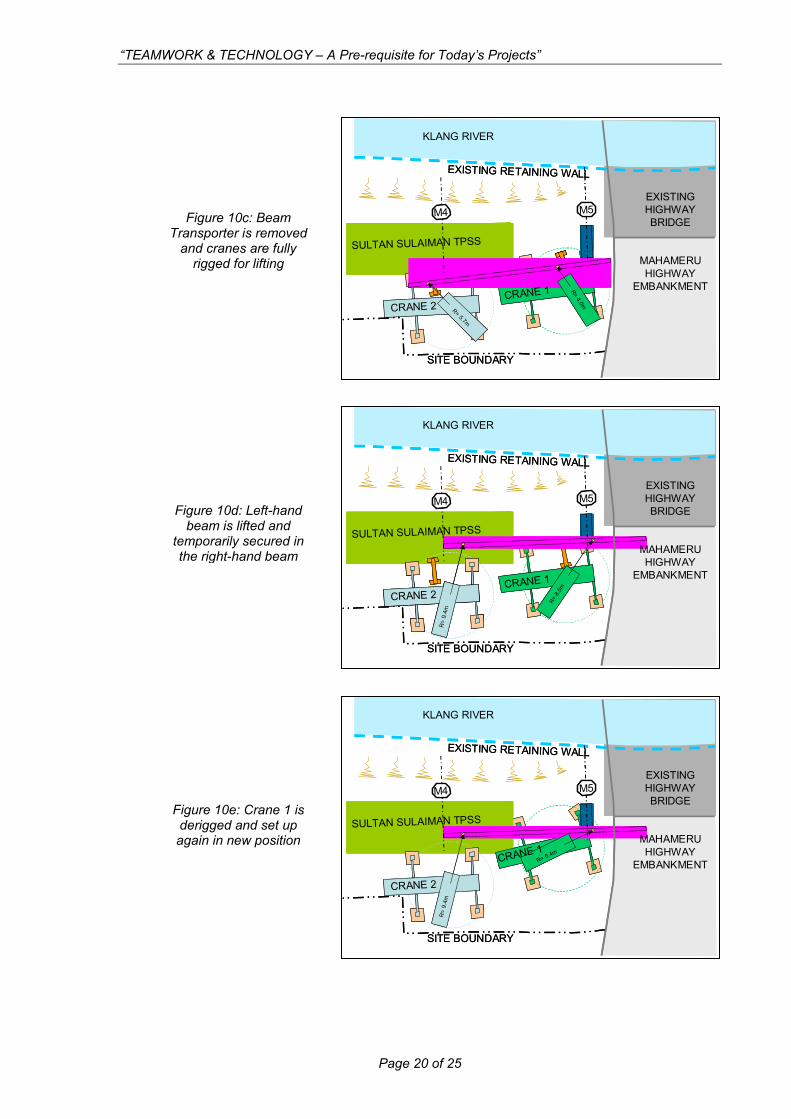
Figure 10c: Beam Transporter is removed
and cranes are fully rigged for lifting
Figure 10d: Left-hand beam is lifted and
temporarily secured inthe right-hand beam
CRANE 1
SITE BOUNDARY
CRANE 2
R=
9.4m
EMBANKMENT
R= 8
.5mCRANE 1
SITE BOUNDARY
CRANE 2
R=
9.4m
CRANE 2
R=
9.4m
EMBANKMENT
R= 8
.5m
M4 M5
EXISTING RETAINING WALL
SULTAN SULAIMAN TPSS
CRANE 2
SITE BOUNDARY
R= 6.4mCRANE 1
EXISTING HIGHWAY BRIDGE
MAHAMERU HIGHWAY
EMBANKMENT
R=
9.4m
KLANG RIVER
M4 M5
EXISTING RETAINING WALL
SULTAN SULAIMAN TPSS
CRANE 2
SITE BOUNDARY
R= 6.4mCRANE 1
EXISTING HIGHWAY BRIDGE
MAHAMERU HIGHWAY
EMBANKMENT
R=
9.4m
KLANG RIVER
Figure 10e: Crane 1 is derigged and set up again in new position
Page 20 of 25
“TEAMWORK & TECHNOLOGY – A Pre-requisite for Today’s Projects”
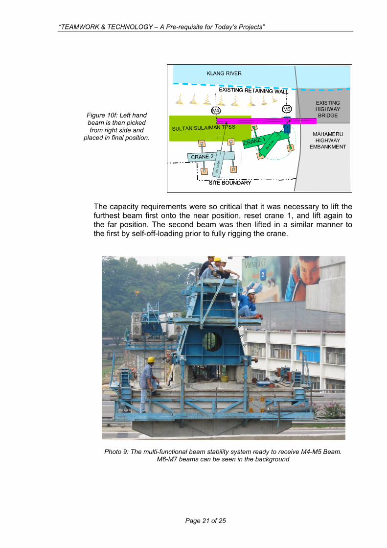
Photo 9: The multi-functional beam stabi ready to receive M4-M5 Beam.
M4 M5
EXISTING RETAINING WALL
SULTAN SULAIMAN TPSS
CRANE 2
SITE BOUNDARY
R= 8.7
m
R=
13.0
m
CRANE 1
EXISTING HIGHWAY BRIDGE
MAHAMERU HIGHWAY
EMBANKMENT
KLANG RIVER
M4 M5
EXISTING RETAINING WALL
SULTAN SULAIMAN TPSS
CRANE 2
SITE BOUNDARY
R= 8.7
m
R=
13.0
m
CRANE 1
EXISTING HIGHWAY BRIDGE
MAHAMERU HIGHWAY
EMBANKMENT
KLANG RIVER
Figure 10f: Left hand beam is then picked from right side and
d in final positplace ion.
The capacity requirements were so critical that it was necessary to lift the furthest beam first onto the near position, reset crane 1, and lift again to the far position. The second beam was then lifted in a similar manner to the first by self-off-loading prior to fully rigging the crane.
lity systemM6-M7 beams can be seen in the background
Page 21 of 25
“TEAMWORK & TECHNOLOGY – A Pre-requisite for Today’s Projects”
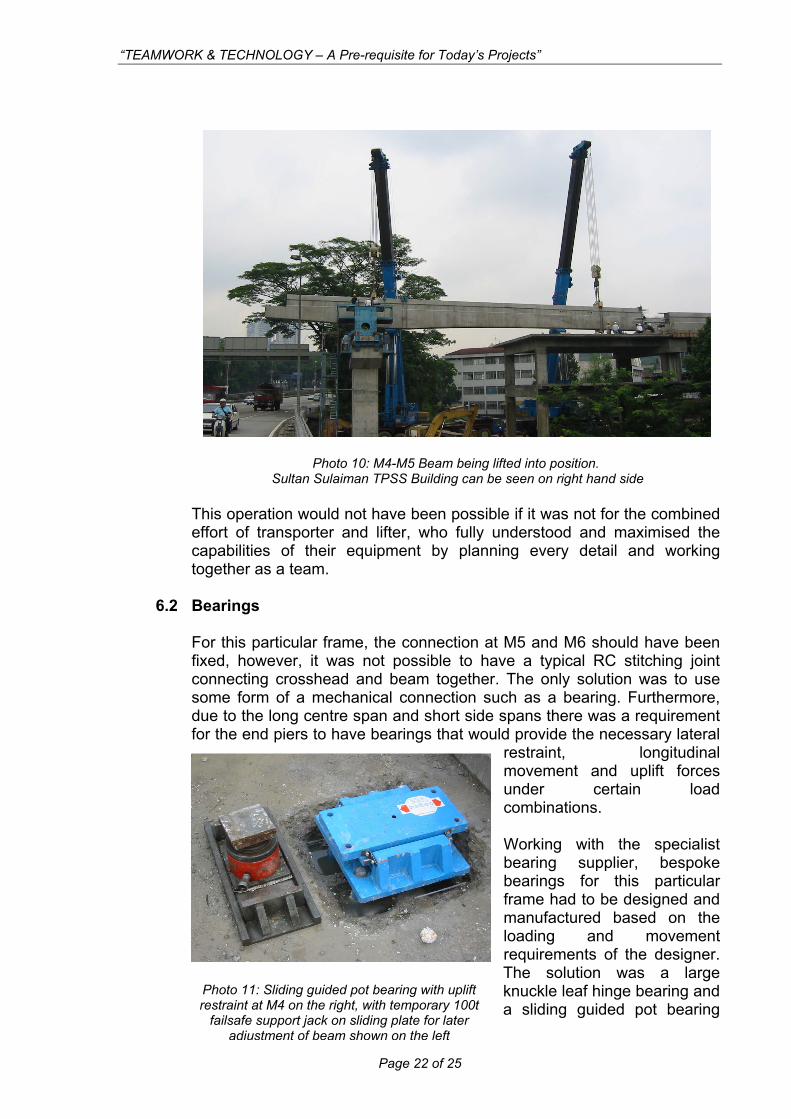
Photo 10: M4-M5 Beam being lifted into position.
Sultan Sulaiman TPSS Building can be seen on right hand side This operation would not have been possible if it was not for the combined effort of transporter and lifter, who fully understood and maximised the capabilities of their equipment by planning every detail and working together as a team.
6.2 Bearings For this particular frame, the connection at M5 and M6 should have been fixed, however, it was not possible to have a typical RC stitching joint connecting crosshead and beam together. The only solution was to use some form of a mechanical connection such as a bearing. Furthermore, due to the long centre span and short side spans there was a requirement for the end piers to have bearings that would provide the necessary lateral
restraint, longitudinal movement and uplift forces under certain load combinations.
Working with the specialist bearing supplier, bespoke bearings for this particular frame had to be designed and manufactured based on the loading and movement requirements of the designer. The solution was a large knuckle leaf hinge bearing and a sliding guided pot bearing r
Photo 11: Sliding guided pot bearing with uplift estraint at M4 on the right, with temporary 100tfailsafe support jack on sliding plate for later
adjustment of beam shown on the left
Page 22 of 25
“TEAMWORK & TECHNOLOGY – A Pre-requisite for Today’s Projects”
with uplift restraint. The congestion of the bearing reinforcement and transfer of forces between connections meant that several rounds of discussions and proposals were made before the successful solution could be issued for construction. (It was of course also necessary to ensure that the designer of the TPSS building structure had catered for the uplift as well as downward forces being transferred into his design.)
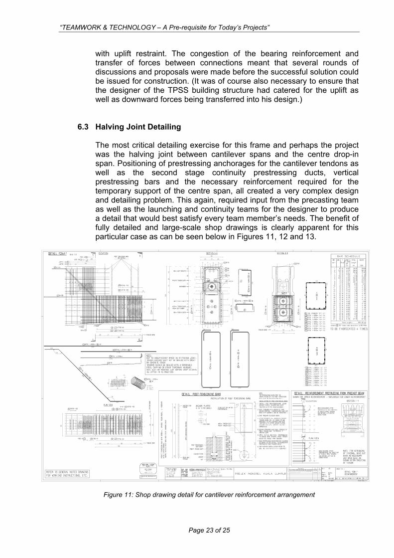
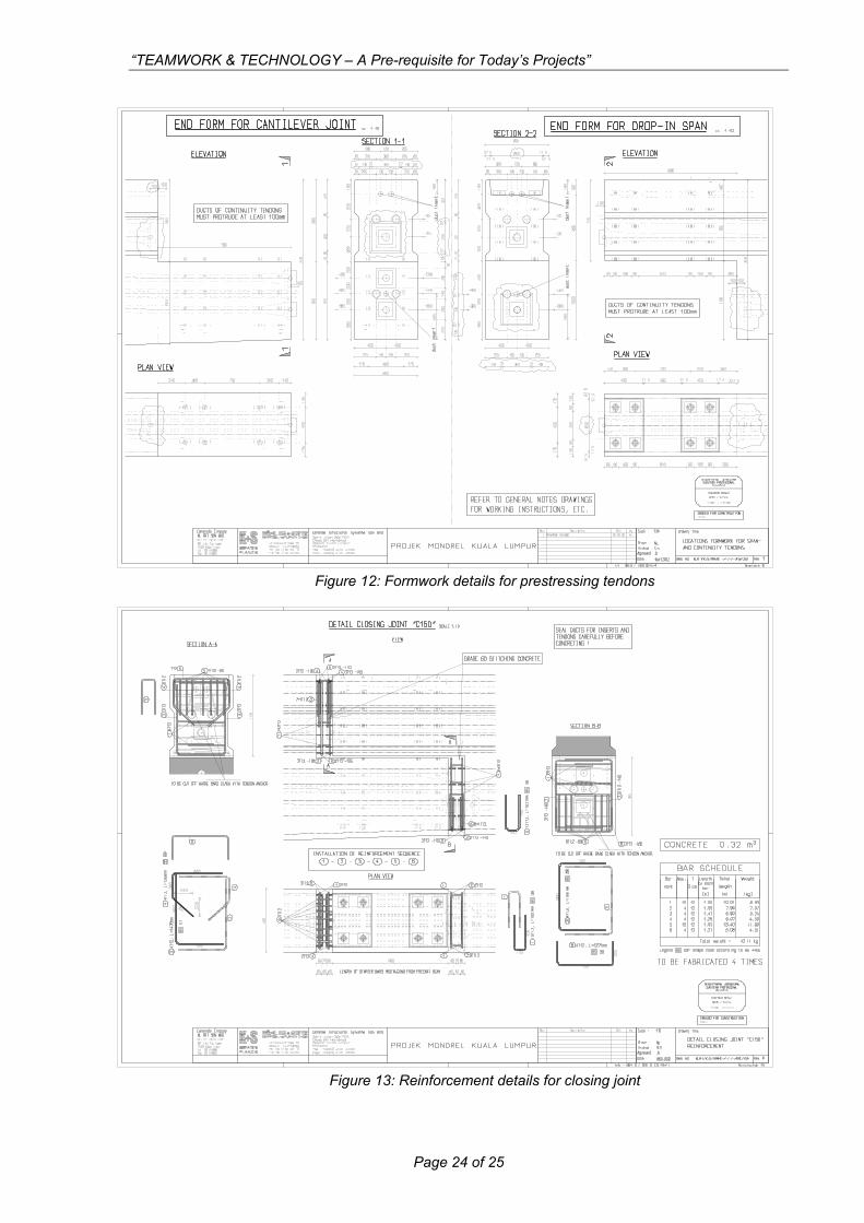
6.3 Halving Joint Detailing The most critical detailing exercise for this frame and perhaps the project was the halving joint between cantilever spans and the centre drop-in span. Positioning of prestressing anchorages for the cantilever tendons as well as the second stage continuity prestressing ducts, vertical prestressing bars and the necessary reinforcement required for the temporary support of the centre span, all created a very complex design and detailing problem. This again, required input from the precasting team as well as the launching and continuity teams for the designer to produce a detail that would best satisfy every team member’s needs. The benefit of fully detailed and large-scale shop drawings is clearly apparent for this particular case as can be seen below in Figures 11, 12 and 13.
Figure 11: Shop drawing detail for cantilever reinforcement arrangement
Page 23 of 25
“TEAMWORK & TECHNOLOGY – A Pre-requisite for Today’s Projects”
Figure 12: Formwork details for prestressing tendons
Figure 13: Reinforcement details for closing joint
Page 24 of 25
“TEAMWORK & TECHNOLOGY – A Pre-requisite for Today’s Projects”
Page 25 of 25
7.0 CONCLUSION
Some of the achievements made on the Kuala Lumpur Monorail Guideway Beam construction were only made possible through teamwork and determination to develop new systems and methods of construction not previously used before. Many of the systems including precasting moulds, transport, lifting and stability temporary works equipment were developed specifically for KLM and many aspects are unique. The study and advancement in the temporary works technology for this project has been at the heart of the success of the KLM guideway construction. One of the key factors to the successful efforts by the whole team has been through increased communication and the use of electronic media. In fact almost all of the design activities by K+S were undertaken in Germany and every document, drawing and detail were sent via email and then printed in Malaysia. Communication with suppliers and specialist consultants was also effected in this manner with lifting and rigging plans, shop drawings and calculations for bearings and fabrication drawings for temporary works equipment all being transmitted to the team members via email. Through the use of .pdf formats and plot files, the designer was assured that the information would be received just as he had intended, and it could not be altered later by those with itchy fingers! The use of electronic communication was very effective and fast when dealing with queries from site personnel, which could be directed straight to the designer and where necessary replies or revised details could be issued almost immediately. With so many projects becoming more complex and the demands from clients to become more innovative and cost effective ever increasing, the exploration of new technology and a more efficient method of working via teamwork have now become a pre-requisite for today’s projects.