techbrief lightweight concrete: shear performance · pdf filelightweight concrete that was...
TRANSCRIPT
TECHBRIEF Lightweight Concrete: Shear Performance FHWA Publication No.: FHWA-HRT-15-021
FHWA Contact: Ben Graybeal, HRDI-40, (202) 493-3122, [email protected]
This document is a technical summary of the Federal Highway Administration report Lightweight Concrete: Shear Performance (FHWA-HRT-15-022).
Objective
Concrete with a unit weight between that of traditional lightweight concrete and normal-weight concrete (NWC) is not covered in the American Association of State Highway and Transportation Officials (AASHTO) Load and Resistance Factor Design (LRFD) Bridge Design Specifications. As part of an effort to address this and other perceived shortcomings in how the specification addresses lightweight concrete and how lightweight concrete is deployed in bridges, research was completed to assess the shear performance of these different density concretes. Thirty full-scale precast, prestressed girder tests were completed, and a database of shear performance results was developed that covered a wide range of concrete densities. Proposed revisions to the AASHTO LRFD Bridge Design Specifications were developed and are presented as part of a framework that addresses the performance of structural concrete as a function of density.
Introduction
Much of the fundamental basis for the current light-weight concrete provisions in the AASHTO LRFD Bridge Design Specifications is research on lightweight concrete from the 1960s. (See references 1 through 5.) The lightweight concrete that was part of this research used traditional mixes of coarse aggregate, fine aggregate, portland cement, and water. Broad-based advancement in concrete technology over the past 50 years has given rise to significant advancements in concrete mechanical and durability performance. Research during the past
Research, Development, and Technology
Turner-Fairbank Highway Research Center
6300 Georgetown Pike
McLean, VA 22101-2296
www.fhwa.dot.gov/research
2
30 years, including the recent National Cooperative Highway Research Program studies on different aspects of high-strength concrete, has resulted in revisions to the AASHTO LRFD Bridge Design Specifications to capitalize on the benefits of high-strength NWC. However, as described by Russell, many of the design equations in the AASHTO LRFD Bridge Design Specifications are based on data that do not include tests of lightweight concrete specimens, particularly structural members with compressive strengths in excess of 6 ksi (41 MPa).(6)
The Federal Highway Administration (FHWA) Turner-Fairbank Highway Research Center (TFHRC) has executed a research program investigating the performance of lightweight concrete with concrete compressive strengths in the range of 6 to 10 ksi (41 to 69 MPa) and equilibrium densities from 0.125 kcf to 0.135 kcf (2,000 to 2,160 kg/m3). The research program used lightweight concrete with three different lightweight aggregates that are intended to be representative of those available in North America. The program included tests of 27 precast/prestressed lightweight concrete girders to investigate topics such as transfer length and development length of prestressing strand, time-dependent prestress losses, and shear strength of lightweight concrete. The development and splice length of mild steel reinforcement used in girders and decks made with lightweight concrete was also investigated using 40 reinforced concrete (RC) beams. While much of the research program focused on structural behavior, it also included a material characterization component wherein the compressive strength, elastic modulus, and splitting tensile strength of
the concrete mixes used in the structural testing program were assessed. One key outcome of the research program is to recommend changes to the AASHTO LRFD Bridge Design Specifications relevant to lightweight concrete.
This document summarizes the results of shear tests conducted on prestressed concrete (PC) girders. The shear tests on lightweight concrete girders tested in this study are included in a database of tests on lightweight concrete and NWC that was collected from test results available in the literature. This document summarizes the database and the analysis of the data-base. Design expressions in the AASHTO LRFD Bridge Design Specifications are compared with the database. Potential revisions to the AASHTO LRFD Bridge Design Specifications relating to shear resistance are presented.
Prestressed Girder Shear Tests Conducted at TFHRC
Lightweight Concrete Mix Designs
The Expanded Shale, Clay, and Slate Institute assisted FHWA in obtaining light-weight concrete mixes that had been used in production. One of the criteria for this research project was to use lightweight aggregate sources that were geographi-cally distributed across the United States. Additional selection criteria included mixes using a large percentage of the coarse aggregate as lightweight coarse aggre-gate, mixes using natural sand as the fine aggregate, and mixes with a target equilib-rium density between 0.125 and 0.135 kcf (2,000 and 2,160 kg/m3). The concrete den-sity needed to be in the range of densities not currently covered by the AASHTO LRFD Bridge Design Specifications.(1)
3
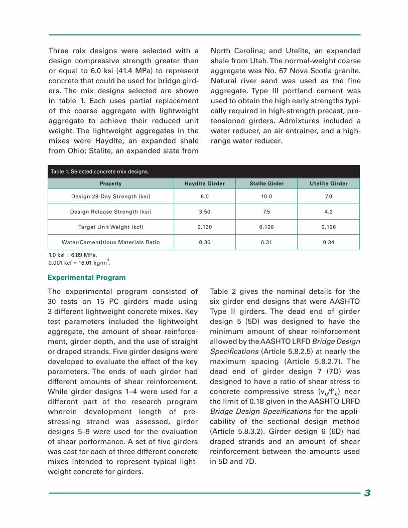
Three mix designs were selected with a design compressive strength greater than or equal to 6.0 ksi (41.4 MPa) to represent concrete that could be used for bridge gird-ers. The mix designs selected are shown in table 1. Each uses partial replacement of the coarse aggregate with lightweight aggregate to achieve their reduced unit weight. The lightweight aggregates in the mixes were Haydite, an expanded shale from Ohio; Stalite, an expanded slate from
North Carolina; and Utelite, an expanded shale from Utah. The normal-weight coarse aggregate was No. 67 Nova Scotia granite. Natural river sand was used as the fine aggregate. Type III portland cement was used to obtain the high early strengths typi-cally required in high-strength precast, pre-tensioned girders. Admixtures included a water reducer, an air entrainer, and a high-range water reducer.
Property Haydite Girder Stalite Girder Utelite Girder
Design 28-Day Strength (ksi) 6.0 10.0 7.0
Design Release Strength (ksi) 3.50 7.5 4.2
Target Unit Weight (kcf) 0.130 0.126 0.126
Water/Cementitious Materials Ratio 0.36 0.31 0.34
Table 1. Selected concrete mix designs.
1.0 ksi = 6.89 MPa.0.001 kcf = 16.01 kg/m
3.
Experimental Program
The experimental program consisted of 30 tests on 15 PC girders made using 3 different lightweight concrete mixes. Key test parameters included the lightweight aggregate, the amount of shear reinforce-ment, girder depth, and the use of straight or draped strands. Five girder designs were developed to evaluate the effect of the key parameters. The ends of each girder had different amounts of shear reinforcement. While girder designs 1–4 were used for a different part of the research program wherein development length of pre- stressing strand was assessed, girder designs 5–9 were used for the evaluation of shear performance. A set of five girders was cast for each of three different concrete mixes intended to represent typical light-weight concrete for girders.
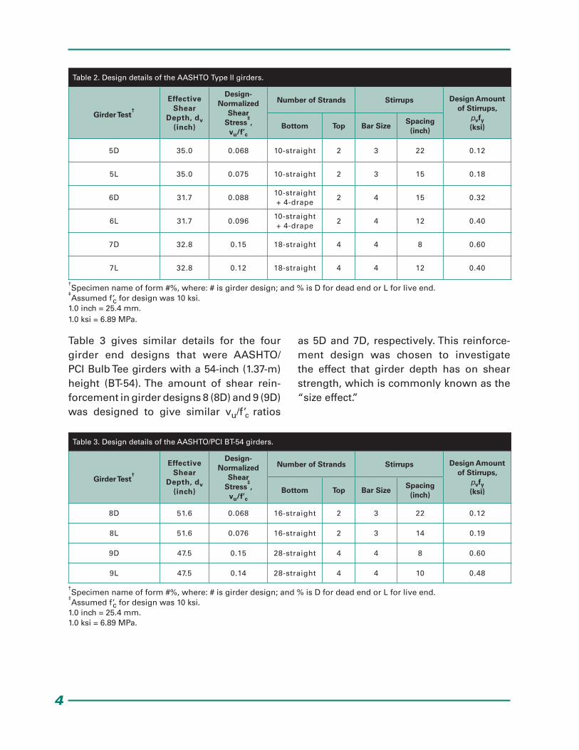
Table 2 gives the nominal details for the six girder end designs that were AASHTO Type II girders. The dead end of girder design 5 (5D) was designed to have the minimum amount of shear reinforcement allowed by the AASHTO LRFD Bridge Design Specifications (Article 5.8.2.5) at nearly the maximum spacing (Article 5.8.2.7). The dead end of girder design 7 (7D) was designed to have a ratio of shear stress to concrete compressive stress (vu/f’c) near the limit of 0.18 given in the AASHTO LRFD Bridge Design Specifications for the appli-cability of the sectional design method (Article 5.8.3.2). Girder design 6 (6D) had draped strands and an amount of shear reinforcement between the amounts used in 5D and 7D.
4
Table 3 gives similar details for the four girder end designs that were AASHTO/PCI Bulb Tee girders with a 54-inch (1.37-m) height (BT-54). The amount of shear rein-forcement in girder designs 8 (8D) and 9 (9D) was designed to give similar vu/f’c ratios
as 5D and 7D, respectively. This reinforce-ment design was chosen to investigate the effect that girder depth has on shear strength, which is commonly known as the “size effect.”
Girder Test†
Effective Shear
Depth, dv (inch)
Design-Normalized
Shear Stress
‡,
vu/f’c
Number of Strands Stirrups Design Amount of Stirrups,
pvfy(ksi)Bottom Top Bar Size
Spacing(inch)
5D 35.0 0.068 10-straight 2 3 22 0.12
5L 35.0 0.075 10-straight 2 3 15 0.18
6D 31.7 0.08810-straight+ 4-drape
2 4 15 0.32
6L 31.7 0.09610-straight+ 4-drape
2 4 12 0.40
7D 32.8 0.15 18-straight 4 4 8 0.60
7L 32.8 0.12 18-straight 4 4 12 0.40
Girder Test†
Effective Shear
Depth, dv (inch)
Design-Normalized
Shear Stress
‡,
vu/f’c
Number of Strands Stirrups Design Amount of Stirrups,
pvfy(ksi)Bottom Top Bar Size
Spacing(inch)
8D 51.6 0.068 16-straight 2 3 22 0.12
8L 51.6 0.076 16-straight 2 3 14 0.19
9D 47.5 0.15 28-straight 4 4 8 0.60
9L 47.5 0.14 28-straight 4 4 10 0.48
Table 2. Design details of the AASHTO Type II girders.
Table 3. Design details of the AASHTO/PCI BT-54 girders.
†Specimen name of form #%, where: # is girder design; and % is D for dead end or L for live end.
‡Assumed f’c for design was 10 ksi.
1.0 inch = 25.4 mm.1.0 ksi = 6.89 MPa.
†Specimen name of form #%, where: # is girder design; and % is D for dead end or L for live end.
‡Assumed f’c for design was 10 ksi.
1.0 inch = 25.4 mm.1.0 ksi = 6.89 MPa.
5
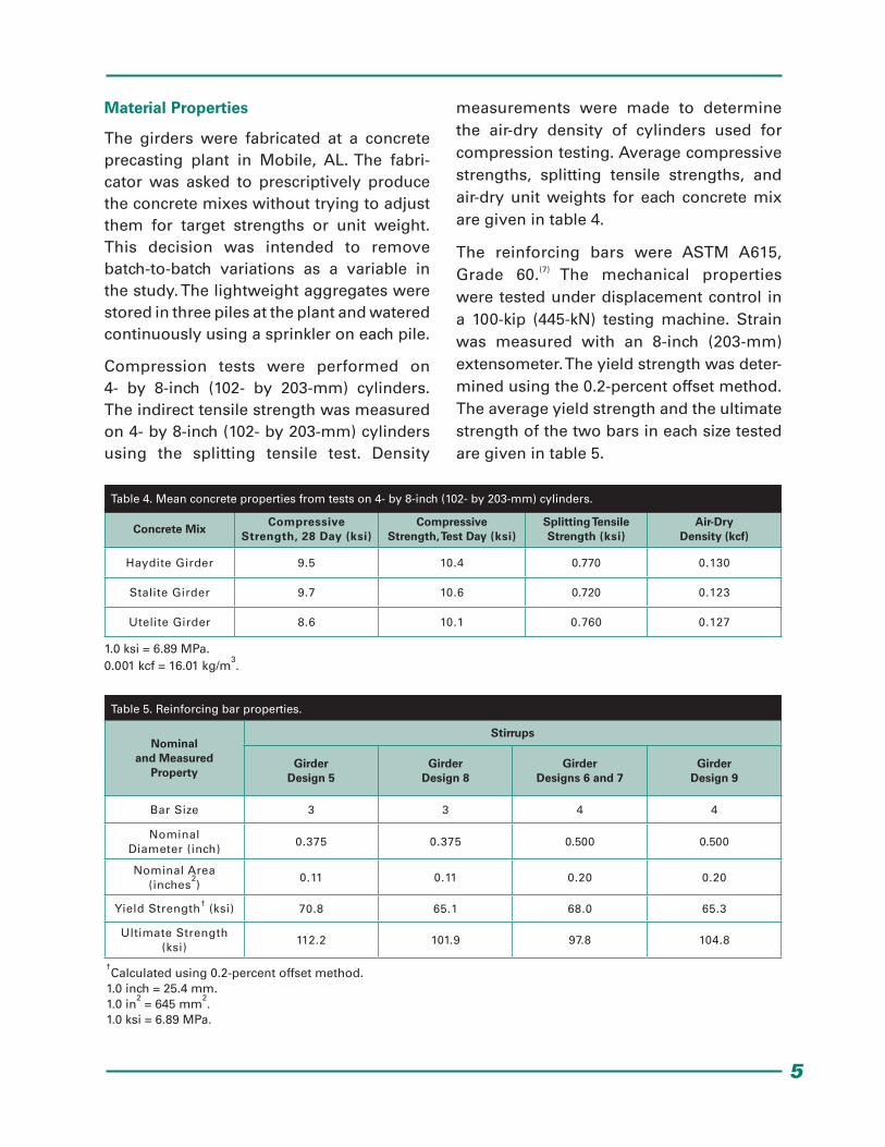
Material Properties
The girders were fabricated at a concrete precasting plant in Mobile, AL. The fabri-cator was asked to prescriptively produce the concrete mixes without trying to adjust them for target strengths or unit weight. This decision was intended to remove batch-to-batch variations as a variable in the study. The lightweight aggregates were stored in three piles at the plant and watered continuously using a sprinkler on each pile.
Compression tests were performed on 4- by 8-inch (102- by 203-mm) cylinders. The indirect tensile strength was measured on 4- by 8-inch (102- by 203-mm) cylinders using the splitting tensile test. Density
measurements were made to determine the air-dry density of cylinders used for compression testing. Average compressive strengths, splitting tensile strengths, and air-dry unit weights for each concrete mix are given in table 4.
The reinforcing bars were ASTM A615, Grade 60.(7) The mechanical properties were tested under displacement control in a 100-kip (445-kN) testing machine. Strain was measured with an 8-inch (203-mm) extensometer. The yield strength was deter-mined using the 0.2-percent offset method. The average yield strength and the ultimate strength of the two bars in each size tested are given in table 5.
Concrete MixCompressive
Strength, 28 Day (ksi)Compressive
Strength, Test Day (ksi)Splitting TensileStrength (ksi)
Air-Dry Density (kcf)
Haydite Girder 9.5 10.4 0.770 0.130
Stalite Girder 9.7 10.6 0.720 0.123
Utelite Girder 8.6 10.1 0.760 0.127
Table 4. Mean concrete properties from tests on 4- by 8-inch (102- by 203-mm) cylinders.
1.0 ksi = 6.89 MPa.0.001 kcf = 16.01 kg/m
3.
Table 5. Reinforcing bar properties.
†Calculated using 0.2-percent offset method.
1.0 inch = 25.4 mm.1.0 in
2 = 645 mm
2.
1.0 ksi = 6.89 MPa.
Nominaland Measured
Property
Stirrups
GirderDesign 5
GirderDesign 8
GirderDesigns 6 and 7
GirderDesign 9
Bar Size 3 3 4 4
Nominal Diameter (inch)
0.375 0.375 0.500 0.500
Nominal Area (inches
2)
0.11 0.11 0.20 0.20
Yield Strength† (ksi) 70.8 65.1 68.0 65.3
Ultimate Strength (ksi)
112.2 101.9 97.8 104.8
6
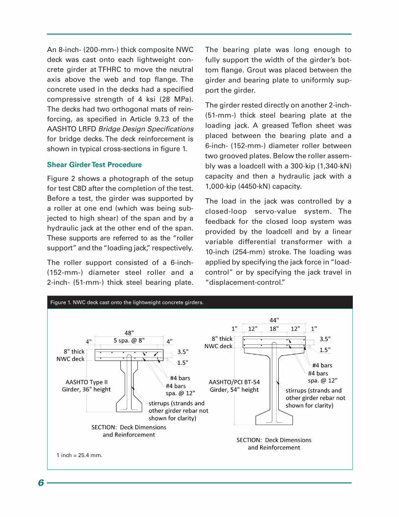
An 8-inch- (200-mm-) thick composite NWC deck was cast onto each lightweight con-crete girder at TFHRC to move the neutral axis above the web and top flange. The concrete used in the decks had a specified compressive strength of 4 ksi (28 MPa). The decks had two orthogonal mats of rein-forcing, as specified in Article 9.7.3 of the AASHTO LRFD Bridge Design Specifications for bridge decks. The deck reinforcement is shown in typical cross-sections in figure 1.
Shear Girder Test Procedure
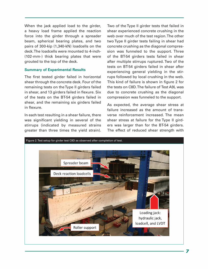
Figure 2 shows a photograph of the setup for test C8D after the completion of the test. Before a test, the girder was supported by a roller at one end (which was being sub-jected to high shear) of the span and by a hydraulic jack at the other end of the span. These supports are referred to as the “roller support” and the “loading jack,” respectively.
The roller support consisted of a 6-inch- (152-mm-) diameter steel roller and a 2-inch- (51-mm-) thick steel bearing plate.
The bearing plate was long enough to fully support the width of the girder’s bot-tom flange. Grout was placed between the girder and bearing plate to uniformly sup-port the girder.
The girder rested directly on another 2-inch- (51-mm-) thick steel bearing plate at the loading jack. A greased Teflon sheet was placed between the bearing plate and a 6-inch- (152-mm-) diameter roller between two grooved plates. Below the roller assem-bly was a loadcell with a 300-kip (1,340-kN) capacity and then a hydraulic jack with a 1,000-kip (4450-kN) capacity.
The load in the jack was controlled by a closed-loop servo-value system. The feedback for the closed loop system was provided by the loadcell and by a linear variable differential transformer with a 10-inch (254-mm) stroke. The loading was applied by specifying the jack force in “load-control” or by specifying the jack travel in “displacement-control.”
Figure 1. NWC deck cast onto the lightweight concrete girders.
1 inch = 25.4 mm.
7
When the jack applied load to the girder, a heavy load frame applied the reaction force into the girder through a spreader beam, spherical bearing plates, and two pairs of 300-kip (1,340-kN) loadcells on the deck. The loadcells were mounted to 4-inch- (102-mm-) thick bearing plates that were grouted to the top of the deck.
Summary of Experimental Results
The first tested girder failed in horizontal shear through the concrete deck. Four of the remaining tests on the Type II girders failed in shear, and 13 girders failed in flexure. Six of the tests on the BT-54 girders failed in shear, and the remaining six girders failed in flexure.
In each test resulting in a shear failure, there was significant yielding in several of the stirrups (indicated by measured strains greater than three times the yield strain).
Two of the Type II girder tests that failed in shear experienced concrete crushing in the web over much of the test region. The other two Type II girder tests failing in shear had concrete crushing as the diagonal compres-sion was funneled to the support. Three of the BT-54 girders tests failed in shear after multiple stirrups ruptured. Two of the tests on BT-54 girders failed in shear after experiencing general yielding in the stir-rups followed by local crushing in the web. This kind of failure is shown in figure 2 for the tests on C8D. The failure of Test A9L was due to concrete crushing as the diagonal compression was funneled to the support.
As expected, the average shear stress at failure increased as the amount of trans-verse reinforcement increased. The mean shear stress at failure for the Type II gird-ers was larger than for the BT-54 girders. The effect of reduced shear strength with
Figure 2. Test setup for girder test C8D as observed after completion of test.
8
increased girder depth was observed for three separate groups of tests. Each group of tests had similar percentages of longi-tudinal and transverse reinforcement. The mean test-day compressive strength was near 10 ksi (69 MPa) for all three girder mixes. No dependency on aggregate was observed in the average shear stress at failure.
All three design procedures in the AASHTO LRFD Bridge Design Specifications gave conservative predictions of shear resistance for the tests failing in shear. The two meth-ods of the General Procedure (GP) gave less conservative predictions of shear resis-tance for the BT-54 girders than the Type II girders. The opposite was observed with the Simplified Procedure, which gave more conservative predictions of shear resis- tance for the BT-54 girders than the Type II girders. All of these predictions were made without modification for lightweight concrete.The high splitting tensile strength of most of the girders did not require modification for lightweight concrete according to Article 5.8.2.2 of the AASHTO LRFD Bridge Design Specifications.
The shear force at web-shear cracking was conservatively predicted by all three design procedures in the AASHTO LRFD Bridge Design Specifications for all of the tests. The GP-equation procedure and the Simplified Procedure gave the most conservative and least conservative predictions of web-shear cracking for both the Type II and BT-54 gird-ers, respectively. All three design proce-dures gave less conservative predictions of web-shear cracking for the BT-54 girders than for the Type II girders.
On average, the three design proce-dures in the AASHTO LRFD Bridge Design Specifications tended to underestimate the web-shear crack inclination angle of
the Type II girders (i.e., the observed crack angle was greater than the predicted angle) and overestimate the web-shear crack inclination angle of the BT-54 girders (i.e., the observed crack angle was less than the predicted angle). An underestima-tion of the inclination angle will result in an increase in the predicted contribution of the stirrups to the nominal shear resistance.
TFHRC Shear Database
A thorough literature review was per-formed to find published journal papers, conference papers, technical reports, and university dissertations that included tests, analysis, or discussions of lightweight con-crete. More than 500 references were found in the literature that mentioned lightweight concrete. These references were reviewed for data from tests on beam and girder specimens. Tests included in the database were limited to data from RC beams and PC beams that culminated in a shear failure. Only test data from published reports were included in the database.
The TFHRC Shear Database consists of data from 886 tests on lightweight concrete specimens. More information about the tests in the database and a full list of refer-ences for the database is included in the associated report.(8)
In addition to data from tests on lightweight concrete, a select number of tests on NWC were also included in the database for comparison. The American Concrete Institute-Deutsche Ausschuss für Stahlbeton (ACI-DafStb) Database has data from 928 specimens.(9,10) A subset of the ACI-DafStb Database with similar concrete compressive strength and specimen height was selected for comparison to the light-weight concrete specimens.
9
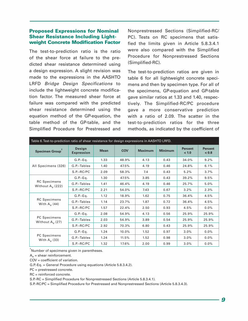
Proposed Expressions for Nominal Shear Resistance Including Light-weight Concrete Modification Factor
The test-to-prediction ratio is the ratio of the shear force at failure to the pre-dicted shear resistance determined using a design expression. A slight revision was made to the expressions in the AASHTO LRFD Bridge Design Specifications to include the lightweight concrete modifica-tion factor. The measured shear force at failure was compared with the predicted shear resistance determined using the equation method of the GP-equation, the table method of the GP-table, and the Simplified Procedure for Prestressed and
Nonprestressed Sections (Simplified-RC/PC). Tests on RC specimens that satis-fied the limits given in Article 5.8.3.4.1 were also compared with the Simplified Procedure for Nonprestressed Sections (Simplified-RC).
The test-to-prediction ratios are given in table 6 for all lightweight concrete speci-mens and then by specimen type. For all of the specimens, GP-equation and GP-table gave similar ratios at 1.33 and 1.40, respec-tively. The Simplified-RC/PC procedure gave a more conservative prediction with a ratio of 2.09. The scatter in the test-to-prediction ratios for the three methods, as indicated by the coefficient of
Specimen Group† Design
ExpressionMean COV Maximum Minimum
Percent < 1.0
Percent < 0.8
All Specimens (326)
G.P.–Eq. 1.33 48.9% 4.13 0.43 34.0% 9.2%
G.P.–Tables 1.40 47.5% 4.19 0.46 24.8% 6.1%
S.P.–RC/PC 2.09 58.3% 7.4 0.43 5.2% 3.7%
RC Specimens Without Av (222)
G.P.–Eq. 1.30 47.5% 3.85 0.43 39.2% 9.5%
G.P.–Tables 1.41 46.4% 4.19 0.46 25.7% 5.0%
S.P.–RC/PC 2.21 54.0% 7.43 0.67 3.2% 2.3%
RC Specimens With Av (44)
G.P.–Eq. 1.12 18.9% 1.62 0.75 36.4% 4.5%
G.P.–Tables 1.14 23.7% 1.87 0.72 36.4% 4.5%
S.P.–RC/PC 1.57 22.4% 2.50 0.93 4.5% 0.0%
PC Specimens Without Av (27)
G.P.–Eq. 2.08 54.9% 4.13 0.56 25.9% 25.9%
G.P.–Tables 2.03 54.9% 3.89 0.54 25.9% 25.9%
S.P.–RC/PC 2.92 70.3% 6.80 0.43 25.9% 25.9%
PC Specimens With Av (33)
G.P.–Eq. 1.24 10.0% 1.52 0.97 3.0% 0.0%
G.P.–Tables 1.24 11.5% 1.52 0.98 3.0% 0.0%
S.P.–RC/PC 1.32 17.6% 2.00 0.99 3.0% 0.0%
Table 6. Test-to-prediction ratio of shear resistance for design expressions in AASHTO LRFD.
†Number of specimens given in parentheses.
Av = shear reinforcement.COV = coefficient of variation.G.P.-Eq. = General Procedure using equations (Article 5.8.3.4.2).PC = prestressed concrete.RC = reinforced concrete.S.P.-RC = Simplified Procedure for Nonprestressed Sections (Article 5.8.3.4.1).S.P.-RC/PC = Simplified Procedure for Prestressed and Nonprestressed Sections (Article 5.8.3.4.3).
10
variation, was high at nearly 50 percent for the GP methods and nearly 60 percent for the Simplified-RC/PC procedure. All three methods have more conservative predic-tions for the RC specimens without shear reinforcement than for RC specimens with shear reinforcement. A similar trend was observed for PC specimens with and with-out shear reinforcement. All three meth-ods gave more conservative predictions for PC specimens without shear reinforcement than for RC specimens without shear rein-forcement. The two GP methods also gave more conservative predictions for PC speci-mens with shear reinforcement than for RC specimens with shear reinforcement. For the Simplified-RC/PC procedure, however, the prediction of RC specimens with shear reinforcement was more conservative than for PC specimens with shear reinforcement.
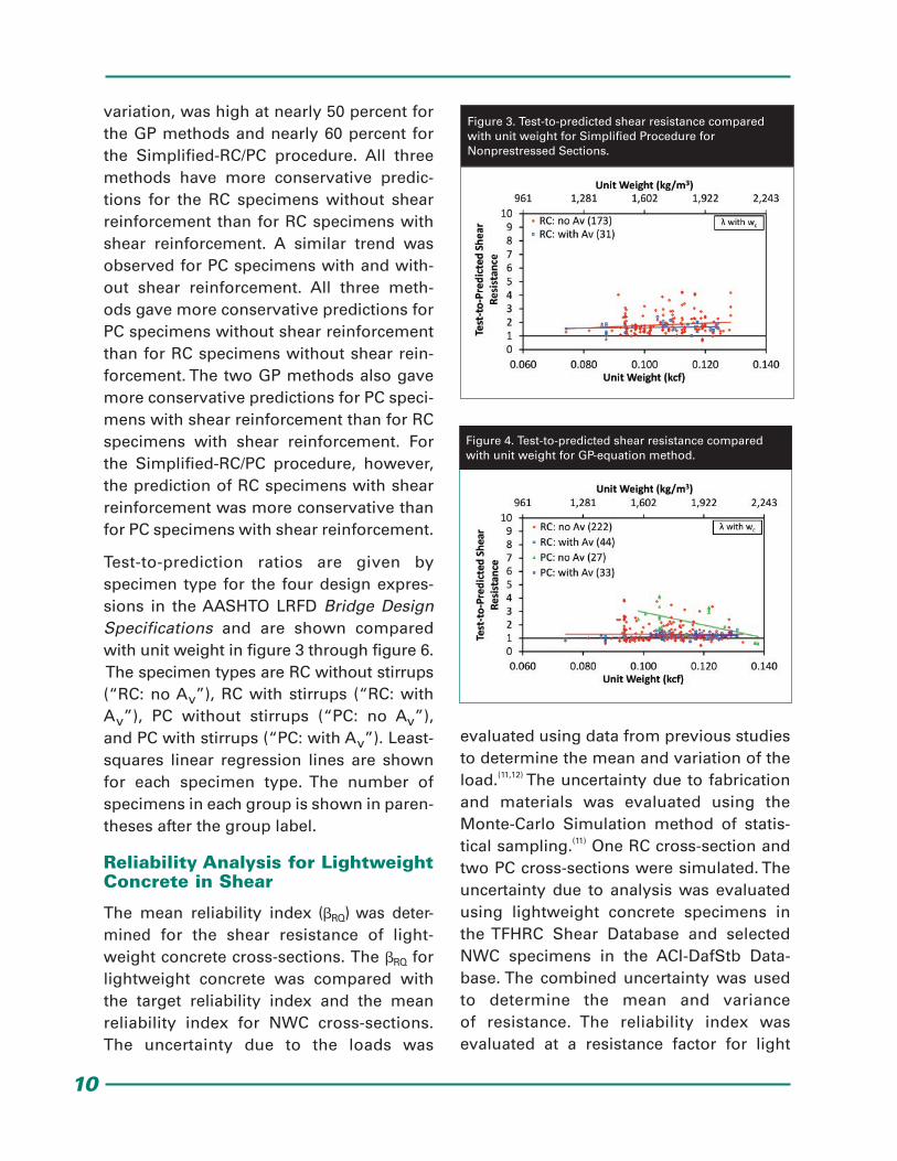
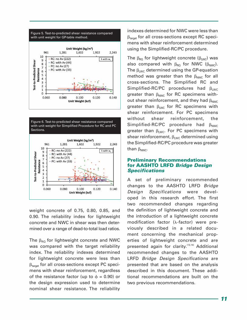
Test-to-prediction ratios are given by specimen type for the four design expres-sions in the AASHTO LRFD Bridge Design Specifications and are shown compared with unit weight in figure 3 through figure 6. The specimen types are RC without stirrups (“RC: no Av”), RC with stirrups (“RC: with Av”), PC without stirrups (“PC: no Av”), and PC with stirrups (“PC: with Av”). Least-squares linear regression lines are shown for each specimen type. The number of specimens in each group is shown in paren-theses after the group label.
Reliability Analysis for Lightweight Concrete in Shear
The mean reliability index (RQ) was deter-mined for the shear resistance of light-weight concrete cross-sections. The RQ for lightweight concrete was compared with the target reliability index and the mean reliability index for NWC cross-sections. The uncertainty due to the loads was
evaluated using data from previous studies to determine the mean and variation of the load.(11,12) The uncertainty due to fabrication and materials was evaluated using the Monte-Carlo Simulation method of statis-tical sampling.(11) One RC cross-section and two PC cross-sections were simulated. The uncertainty due to analysis was evaluated using lightweight concrete specimens in the TFHRC Shear Database and selected NWC specimens in the ACI-DafStb Data-base. The combined uncertainty was used to determine the mean and variance of resistance. The reliability index was evaluated at a resistance factor for light
Figure 3. Test-to-predicted shear resistance compared with unit weight for Simplified Procedure for Nonprestressed Sections.
Figure 4. Test-to-predicted shear resistance compared with unit weight for GP-equation method.
11
weight concrete of 0.75, 0.80, 0.85, and 0.90. The reliability index for lightweight concrete and NWC in shear was then deter-mined over a range of dead-to-total load ratios.
The RQ for lightweight concrete and NWC was compared with the target reliability index. The reliability indexes determined for lightweight concrete were less than target for all cross-sections except PC speci-mens with shear reinforcement, regardless of the resistance factor (up to = 0.90) or the design expression used to determine nominal shear resistance. The reliability
indexes determined for NWC were less than target for all cross-sections except RC speci-mens with shear reinforcement determined using the Simplified-RC/PC procedure.
The RQ for lightweight concrete (LWC) was also compared with RQ for NWC (NWC). The LWC determined using the GP-equation method was greater than the NWC for all cross-sections. The Simplified RC and Simplified-RC/PC procedures had LWC greater than NWC for RC specimens with-out shear reinforcement, and they had NWC greater than LWC for RC specimens with shear reinforcement. For PC specimens without shear reinforcement, the Simplified-RC/PC procedure had NWC
greater than LWC. For PC specimens with shear reinforcement, LWC determined using the Simplified-RC/PC procedure was greater than NWC.
Preliminary Recommendations for AASHTO LRFD Bridge Design Specifications
A set of preliminary recommended changes to the AASHTO LRFD Bridge Design Specifications were devel-oped in this research effort. The first two recommended changes regarding the definition of lightweight concrete and the introduction of a lightweight concrete modification factor (-factor) were pre-viously described in a related docu-ment concerning the mechanical prop-erties of lightweight concrete and are presented again for clarity.(13,14) Additional recommended changes to the AASHTO LRFD Bridge Design Specifications are presented that are based on the analysis described in this document. These addi-tional recommendations are built on the two previous recommendations.
Figure 6. Test-to-predicted shear resistance compared with unit weight for Simplified Procedure for RC and PC Sections.
Figure 5. Test-to-predicted shear resistance compared with unit weight for GP-table method.
12
Three types of changes are recommended regarding the shear performance of light-weight concrete as a result of the database analyses summarized in this document. The analysis of the TFHRC Shear Database included an evaluation of design expres- sions for nominal shear resistance in the AASHTO LRFD Bridge Design Specifications. The design expression for the minimum amount of transverse reinforcement was also evaluated using the TFHRC Shear Database. Lightweight concrete specimens in the TFHRC Shear Database and NWC specimens in the ACI-DafStb Database were used as part of a reliability analysis to determine the appropriate resistance factor for lightweight concrete.
The design expressions for nominal shear resistance and minimum transverse rein-forcement include the recommended new expression for the -factor. The -factor is not based on the proportions of constituent materials and includes tests from types of mix designs that are not explicitly permit-ted by the current edition of the AASHTO LRFD Bridge Design Specifications.(1) These mix types include specified-density lightweight concrete (typically a blend of lightweight and normal-weight coarse aggregate) and inverted mixes (normal- weight coarse and lightweight fine aggregate). The recommend new expres-sion for the -factor is based on unit weight and splitting tensile strength, and as a result, the definitions of sand-lightweight concrete and all-lightweight concrete would no longer be needed.
Proposed Definition for Lightweight Concrete
The definition for lightweight concrete in Article 5.2 of the AASHTO LRFD
Bridge Design Specifications limits the unit weight for lightweight concrete to 0.120 kcf (1,920 kg/m3) and includes definitions for sand-lightweight concrete and all-lightweight concrete. The proposed definition for lightweight concrete expands the range of unit weights and eliminates the definitions for terms relating to the constituent materials in lightweight concrete. The proposed definition for light-weight concrete is as follows:
Lightweight Concrete—Concrete containing lightweight aggregate conforming to AASHTO M 195 and having an equilibrium density not exceeding 0.135 kcf, as determined by ASTM C567.
Proposed Expression for Lightweight Concrete Modification Factor
The concept of including a modification fac-tor for lightweight concrete in expressions for predicting nominal resistance is included in many articles of the AASHTO LRFD Bridge Design Specifications. However, a single unified expression or lightweight concrete modification factor is not specified. This section proposes a new term, the -factor, to quantify the modi-fication in nominal resistance that could be included in any expression for nominal resistance. The -factor relates to the mate-rial properties of structural lightweight concrete, so the new article for the definition for the -factor could be located in Article 5.4.2, “Normal Weight and Structural Lightweight Concrete.” The -factor will be referred to as Article 5.4.2.8 in the present document. The proposed text for the -factor is as follows:
13
Where lightweight aggregate concretes are used, the lightweight concrete modification factor, , shall be determined using the equation in figure 7 where fct is specified.
Where fct is not specified, shall be deter-mined using the equation in figure 8.
Where:
fct = Concrete splitting tensile strength in ksi.
f’c = Compressive strength in ksi.
wc = Concrete unit weight in kcf.
= Lightweight concrete modification factor.
Proposed Design Expressions for Nominal Shear Resistance
Three recommended changes to the AASHTO LRFD Bridge Design Specifications involve adding the -factor to the three terms for the nominal shear resistance provided by the concrete (i.e., Vc, Vci, Vcw). The change to the Vc term is described first and includes the existing language for the nominal shear resistance (Vn). The changes to Vci and Vcw are presented after the expression for Vc. The proposed design expression for nominal shear resistance
provided by tensile stresses in the concrete (Vc) is as follows:
The nominal shear resistance, Vn, shall be determined using the equation in figure 9.
Where:
bv = Effective web width (inch).
dv = Effective shear depth (inch).
Vc = Nominal shear resistance provided by tensile stresses in the concrete (kip).
Vn = Nominal shear resistance of the section (kip).
Vp = Component of the effective prestress-ing force in the direction of the applied shear (kip).
Vs = Nominal shear resistance provided by the shear reinforcement (kip).
Where the procedures of Articles 5.8.3.4.1 or 5.8.3.4.2 are used, Vc shall be determined using the equation in figure 10.
Where the procedures of Article 5.8.3.4.3 are used, Vc shall be determined as the lesser of Vci (determined using the equation in figure 11) and Vcw (determined using the equation in figure 12).
Figure 7. Expression for -factor with fct specified.
Figure 8. Expression for -factor with fct specified not specified.
Figure 9. Expression for Vn.
Figure 10. Expression for Vc.
14
Where:
fpc = Compressive stress at the centroid of the concrete after all prestress losses have occurred (ksi).
Mcre = Moment causing flexural cracking at the section due to externally applied loads (kip-inch).
Mmax = Maximum factored moment at the section due to externally applied loads (kip-inch).
Vci = Nominal shear resistance provided by concrete when inclined cracking results from combined shear and moment (kip).
Vcw = Nominal shear resistance provided by concrete when inclined cracking results from excessive principal tensions in the web (kip).
Vd = Shear force at the section due to unfac-tored dead load (kip).
Vi = Factored shear force at the section due to externally applied loads occurring simul-taneously with Mmax (kip).
= factor indicating ability of diagonally cracked concrete to transmit tension and shear.
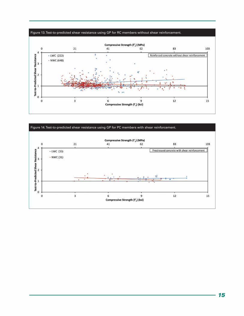
The ratio of test-to-predicted shear resis-tance for lightweight concrete specimens in the TFHRC Shear Database is compared with compressive strength in figure 13 and figure 14. Figure 13 shows the ratios for RC specimens without shear reinforce-ment, and figure 14 shows the ratios for PC specimens with shear reinforcement. For comparison, the ratios for NWC speci-mens in the ACI-DafStb Database are also shown in each figure. The nominal shear resistance was determined using the GP with the equations for and given in Article 5.8.3.4.2 and the new expression -factor. Regression lines are shown for the lightweight concrete specimens and NWC specimens. The regression line for the lightweight concrete specimens is slightly greater than the regression line for NWC specimens for nearly all values of compres-sive strength.
Figure 11. Expression for Vci.
Figure 12. Expression for Vcw.
15
Figure 13. Test-to-predicted shear resistance using GP for RC members without shear reinforcement.
Figure 14. Test-to-predicted shear resistance using GP for PC members with shear reinforcement.
16
Proposed Design Expression for Minimum Transverse Reinforcement
A recommended change to the AASHTO LRFD Bridge Design Specifications involves adding the new expression for -factor to the design expression for minimum trans-verse reinforcement. The proposed design expression for the minimum transverse reinforcement is as follows:
Except for segmental post-tensioned con-crete box girder bridges, where transverse reinforcement is required, as specified in Article 5.8.2.4, the area of steel shall satisfy the equation in figure 15:
Where:
Av = Area of transverse reinforcement within distance s (inch2).
s = Spacing of shear reinforcement (inch).
fy = Yield strength of transverse reinforce-ment (ksi).
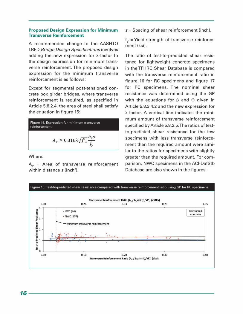
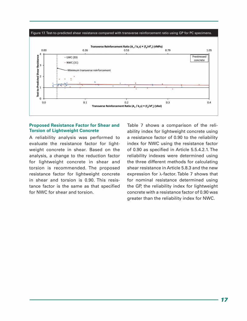
The ratio of test-to-predicted shear resis-tance for lightweight concrete specimens in the TFHRC Shear Database is compared with the transverse reinforcement ratio in figure 16 for RC specimens and figure 17 for PC specimens. The nominal shear resistance was determined using the GP with the equations for and given in Article 5.8.3.4.2 and the new expression for -factor. A vertical line indicates the mini-mum amount of transverse reinforcement specified by Article 5.8.2.5. The ratios of test-to-predicted shear resistance for the few specimens with less transverse reinforce- ment than the required amount were simi-lar to the ratios for specimens with slightly greater than the required amount. For com-parison, NWC specimens in the ACI-DafStb Database are also shown in the figures.
Figure 15. Expression for minimum transverse reinforcement.
Figure 16. Test-to-predicted shear resistance compared with transverse reinforcement ratio using GP for RC specimens.
17
Proposed Resistance Factor for Shear and Torsion of Lightweight Concrete
A reliability analysis was performed to evaluate the resistance factor for light-weight concrete in shear. Based on the analysis, a change to the reduction factor for lightweight concrete in shear and torsion is recommended. The proposed resistance factor for lightweight concrete in shear and torsion is 0.90. This resis- tance factor is the same as that specified for NWC for shear and torsion.
Table 7 shows a comparison of the reli-ability index for lightweight concrete using a resistance factor of 0.90 to the reliability index for NWC using the resistance factor of 0.90 as specified in Article 5.5.4.2.1. The reliability indexes were determined using the three different methods for calculating shear resistance in Article 5.8.3 and the new expression for -factor. Table 7 shows that for nominal resistance determined using the GP, the reliability index for lightweight concrete with a resistance factor of 0.90 was greater than the reliability index for NWC.
Figure 17. Test-to-predicted shear resistance compared with transverse reinforcement ratio using GP for PC specimens.

18
Concluding Remarks
This document describes shear tests on lightweight concrete prestressed girders, summarizes a database of lightweight concrete and NWC shear tests, describes a reliability analysis, and presents potential revisions to the AASHTO LRFD Bridge Design Specifications relating to the shear resistance of lightweight concrete. The proposed design expressions for shear resistance were compared with test results in a database collected as part of this research effort. A full description of the database and the development and evaluation of prediction expressions is included in the full report.(8) Future phases of this research program and analysis effort will focus on other structural per- formance attributes as related to light-weight concrete. The test results will be
compared with the prediction expressions for nominal resistance in the AASHTO LRFD Bridge Design Specifications incorporating appropriate proposed revisions for light-weight concrete mechanical properties.
References
1. AASHTO (2012), AASHTO LRFD Bridge Design Specifications, Customary U.S. Units, 6th Ed., Washington, DC.
2. ACI Committee 213 (1967), “Guide for Structural Lightweight Aggregate Concrete,” ACI Journal, 64(8), American Concrete Institute, August, pp. 433–469.
3. Hanson, J.A. (1961), “Tensile Strength and Diagonal Tension Resistance of Structural Lightweight Concrete,” ACI Journal Proceedings, 58(1), July, pp. 1–40.
Table 7. Reliability index for lightweight concrete and NWC in shear.
G.P.-Eq. = General Procedure using equations (Article 5.8.3.4.2).NWC = normal-weight concrete.PC = prestressed concrete.RC = reinforced concrete.S.P.-RC = Simplified Procedure for Nonprestressed Sections (Article 5.8.3.4.1).S.P.-RC/PC = Simplified Procedure for Prestressed and Nonprestressed Sections (Article 5.8.3.4.3).
Specimen Group Design Expression
Reliability Index (RQ)
Lightweight Concrete ( = 0.90)
NWC ( = 0.90)
RC Beam Without Shear Reinforcement
S.P.-RC 2.99 2.73
G.P.-Eq. 2.69 2.43
S.P.-RC/PC 2.91 2.41
RC Beam With Shear Reinforcement
S.P.-RC 3.07 3.43
G.P.-Eq. 3.07 2.79
S.P.-RC/PC 2.92 3.70
PC Girder Without Shear Reinforcementt
G.P.-Eq. 2.00 1.83
S.P.-RC/PC 1.54 3.02
PC Girder With Shear Reinforcement
G.P.-Eq. 4.75 3.16
S.P.-RC/PC 4.10 2.81
19
4. Ivey, D.L., and Buth, E. (1966), “Splitting Tension Test of Structural Lightweight Concrete,” ASTM Journal of Materials, 1(4), pp. 859–871.
5. Pauw, A. (1960), “Static Modulus of Elasticity of Concrete as Affected by Density,” ACI Journal, 57(6), December, pp. 679–687.
6. Russell, H. (2007), Synthesis of Research and Provisions Regarding the Use of Lightweight Concrete in Highway Bridges, FHWA-HRT-07-053, FHWA, Washington, DC.
7. ASTM A615 (2012), “Standard Specification for Deformed and Plain Carbon-Steel Bars for Concrete Reinforcement,” Book of Standards, 01.04, West Conshohocken, PA.
8. Greene, G., and Graybeal, B. (2015), Lightweight Concrete: Shear Performance, FHWA-HRT-15-022, FHWA, Washington, DC.
9. Reineck, K.-H., Kuchma, D.A., and with Fitik, B. (2010), Extended Databases With Shear Tests on Structural Concrete Beams Without and With Stirrups for the Assessment of Shear Design Pro-cedures, Research Report, Institut für Leichtbau Entwerfen und Konstruieren (ILEK) (Institute for Lightweight Structures and Conceptual Design), University of Stuttgart and University of Illinois, Champaign, Urbana, July.
10. Reineck, K.-H., Bentz, E., Fitik, B., Kuchma, D.A., and Bayrak, O. (2013), “The ACI-DAfStb Database with Shear Tests on Slender Reinforced Concrete Beams Without Stirrups,” ACI Structural Journal, 110(5), September–October, pp. 867–875.
11. Nowak, A.S., and Collins, K. (2000), Reliability of Structures, 2nd Ed., McGraw-Hill Higher Education, New York, NY.
12. Paczkowski, P., and Nowak, A.S. (2010), Reliability Models for Shear in Lightweight Reinforced Concrete Bridges, Concrete Bridge Conference, Phoenix, AZ.
13. Greene, G., and Graybeal, B. (2013), Lightweight Concrete: Mechanical Properties, FHWA-HRT-13-061, FHWA, Washington, DC.
14. Greene, G., and Graybeal, B. (2013), Lightweight Concrete: Mechanical Properties, National Technical Information Service Report No. PB2013 -107688, FHWA, Washington, DC.
20
APRIL 2015 FHWA-HRT-15-021
HRDI-40/04-15(200)E
Researchers—This study was led by Ben Graybeal at FHWA’s TFHRC. It was conducted by Gary Greene of PSI, Inc. through laboratory support contract DTFH61-10-D-00017. For additional information, contact Ben Graybeal at (202) 493-3122 or in the FHWA Office of Infrastructure Research and Development lo-cated at 6300 Georgetown Pike, McLean, VA, 22101-2296.
Distribution—This TechBrief is being distributed according to a standard distribution. Direct distribu-tion is being made to the Divisions and Resource Center.
Availability—This TechBrief may be obtained from the FHWA Product Distribution Center by email to [email protected], fax to (814) 239-2156, phone to (814) 239-1160, or online at http://www.fhwa.dot.gov/research.
Key Words—Lightweight concrete, bridge design, AASHTO LRFD design specifications.
Notice—This document is disseminated under the sponsorship of the U.S. Department of Transportation in the interest of information exchange. The U.S. Government assumes no liability for the use of the information contained in this document. The U.S. Government does not endorse prod-ucts or manufacturers. Trademarks or manufacturers’ names appear in this TechBrief only because they are considered essential to the objective of the document.
Quality Assurance Statement—The Federal Highway Administration provides high-quality informa-tion to serve Government, industry, and the public in a manner that promotes public understanding. Standards and policies are used to ensure and maximize the quality, objectivity, utility, and integrity of its information. FHWA periodically reviews quality issues and adjusts its programs and processes to ensure continuous quality improvement.