techn ic al bulle tin no. 12 - modern taş kolon sistemleri - …sentezinsaat.com.tr/pdf/tb12-proper...
TRANSCRIPT

This Technical Bulletin describes proper field modulus load testing procedures to validate the design
and construction of columnar ground improvement elements for foundation support. This bulletin is
important because it establishes the appropriate top of pier stresses to be applied during field modulus
load verification testing. Proper verification testing determines both the stiffness and strength of the pier.
Stiff Geopier elements attract a higher portion of the load compared to the surrounding matrix soils. Thus,
running the modulus load test based on the service limit state top of pier stress is fundamental towards
demonstrating that the element exhibits a safe response during service loading. Because the top of pier
stress is much higher than the average footing bearing pressure, methods that suggest that the load test
be performed to 2x the footing bearing pressure are inappropriate. Performing modulus testing to at least
150% of the design or limit state top of pier stress has been the standard of practice on Geopier ground
improvement projects (several thousand as of this publication) and meets the intent of the International
Building Code (IBC) and local building codes with respect to shallow foundation support.
1. design of geopier foundation support
Geopier soil reinforcing elements are designed using a two-layer model to control foundation settlements (Figure 1). The “upper zone” is defined by the depth of the Geopier elements which is a combination of the shaft length (Hs) and bulb
length which is typically assumed equal to the Geopier element diameter (D). The “lower zone” is the zone of unreinforced soil below the tip of the Geopier elements subject to footing stresses.
TeCHnICal BulleTIn
PROPeR lOaD TeSTInG PROCeDuReS TO VeRIFY aDeQuaTe DeSIGn OF GeOPIeR® SuPPORTeD FOunDaTIOn SYSTeMS
nO. 12

PaGe 2
The total foundation settlement is estimated using equation 1 by summing the estimated settlement in the upper zone and the estimated settlement in the lower zone:
STOT = Suz+ SlZ eq. 1.
1.1. lower zone settlements
Settlements in the lower zone are computed using conventional geotechnical settlement methods that involve: estimating the depth of stress influence below the footing bottom (typically extended to twice the footing width for square footings), estimating the footing-induced stress in the lower zone (computed as the product of the footing stress and conventional chart solutions for stress influence factors), and estimating the compressibility of the lower zone soils. lower zone settlements (SlZ) in granular soils are typically estimated as:
SlZ = ∙ HlZ, eq. 2.
where q is the average footing-bottom stress, IlZ
is the stress influence factor in the lower zone, HlZ is the thickness of the lower zone, and elZ is the elastic modulus of the soil in the lower zone.
For soils that consolidate with time, lower zone settlements may be computed as:
SlZ = HlZ ∙ cϵ ∙ log , eq. 3.
where cϵ is the slope of the virgin or recompression curve, p0 is the initial vertical effective stress at the middle of the lower zone layer prior to installation of the footing, and pf is the final vertical effective stress after the footing load has been applied.
1.2. upper zone settlements
For footings less than about 15 feet wide and for Geopier elements up to about 15 feet long or grouted/concrete elements of any length, upper zone settlements may be computed based on a spring analogy per lawton et al. 1994 where the Geopier elements act as stiff springs and the matrix soils between the piers acts as softer springs.
q ∙ IlZ
elZ
( )PfP0
Figure 1. Two-layer Method to estimate
Foundation Settlements

PaGe 3
Figure 2. upper Zone Spring analogy
The concrete footing is rigid relative to the foundation materials, thus, the stresses applied to the composite foundation materials depend on their relative stiffnesses and area coverage. The total downward force (Q) on the footing is the product of composite stress (q) and the footing area (a) and is resisted by a total upward resisting force in the Geopier elements (Qg) and matrix soil (Qm):
Q = q ∙ a = Qg + Qm = qg ∙ ag + qm ∙ am , eq. 4.
where qg is the top of pier stress, ag is the cross sectional area of the Geopier elements, qm is the vertical stress applied to the matrix soil, and am is the area of the matrix soil in contact with the footing bottom.
Because the footing is rigid compared to the foundation materials, the settlement of the Geopier element equals the settlement of the matrix soil. Per the spring analogy, the settlement of the foundation can either be written in terms of Geopier stress and Geopier stiffness modulus (kg) or in terms of the matrix soil stress and matrix soil stiffness modulus (km):
SuZ = = . eq. 5.
equation 5 can then be rewritten to express the matrix soil stress in terms of Geopier stress and Geopier/matrix soil stiffness ratio (Rs):
qm = qg ∙ = = . eq. 6.
qg qm
kg km
km qgkg kg
km
qgRs
PaGe 4
To validate the Geopier design parameters selected for a specific project, a modulus load test is performed on single test pier typically constructed in the “worst” area of the site (i.e. area containing the softest soil conditions) under conservative loading conditions. Modulus tests are conducted to a pressure equal to at least 150% of the maximum design top of pier stress to assure a reasonable level of safety which supports long term settlement control and demonstrates that the Geopier element has adequate strength. Performing modulus testing beyond the limit state top of pier stress meets the intent of the International Building Code (IBC) and local building codes with respect to shallow foundation support.
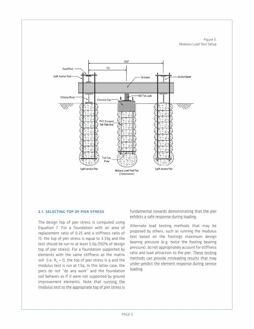
a schematic of a typical compression modulus load test is presented in Figure 3. a jack applies compressive loads to the top of the Geopier elements. The test frame transfers the reactions to uplift elements or other anchorage elements. The test Geopier element is equipped with a tell-tale plate at the bottom of the pier so that bottom of pier deflection measurements may be taken during modulus load testing. The purpose of the tell-tale is to add insight into the mode of stress transfer and pier deformation during testing.
2. modulus load testing
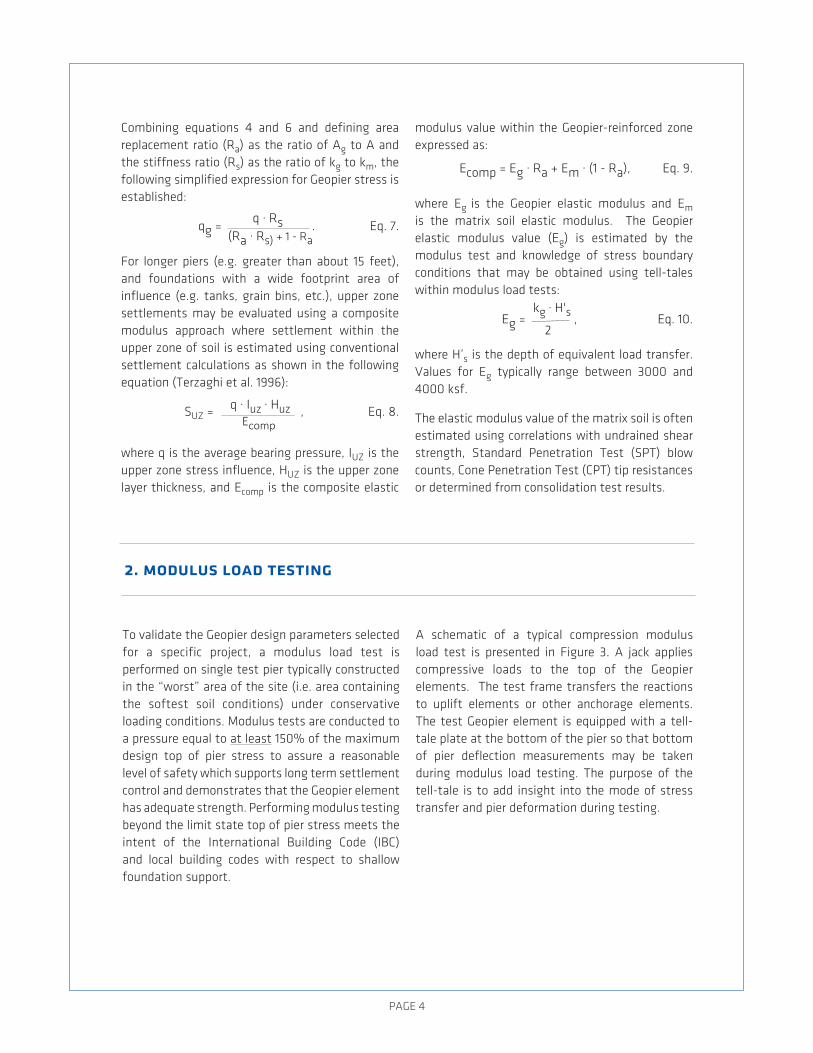
Combining equations 4 and 6 and defining area replacement ratio (Ra) as the ratio of ag to a and the stiffness ratio (Rs) as the ratio of kg to km, the following simplified expression for Geopier stress is established:
qg = . eq. 7.
For longer piers (e.g. greater than about 15 feet), and foundations with a wide footprint area of influence (e.g. tanks, grain bins, etc.), upper zone settlements may be evaluated using a composite modulus approach where settlement within the upper zone of soil is estimated using conventional settlement calculations as shown in the following equation (Terzaghi et al. 1996):
SuZ = q ∙ Iuz ∙ HuzEcomp
, eq. 8.
where q is the average bearing pressure, IuZ is the upper zone stress influence, HuZ is the upper zone layer thickness, and ecomp is the composite elastic
modulus value within the Geopier-reinforced zone expressed as:
ecomp = eg ∙ Ra + em ∙ (1 - Ra), eq. 9.
where eg is the Geopier elastic modulus and em is the matrix soil elastic modulus. The Geopier elastic modulus value (eg) is estimated by the modulus test and knowledge of stress boundary conditions that may be obtained using tell-tales within modulus load tests:
eg = , eq. 10.
where H’s is the depth of equivalent load transfer. Values for eg typically range between 3000 and 4000 ksf.
The elastic modulus value of the matrix soil is often estimated using correlations with undrained shear strength, Standard Penetration Test (SPT) blow counts, Cone Penetration Test (CPT) tip resistances or determined from consolidation test results.
q ∙ Rs(Ra ∙ Rs) + 1 - Ra
kg ∙ H's2
PaGe 5
Figure 3. Modulus load Test Setup
2.1. selecting top of pier stress
The design top of pier stress is computed using equation 7. For a foundation with an area of replacement ratio of 0.25 and a stiffness ratio of 15, the top of pier stress is equal to 3.33q and the test should be run to at least 5.0q (150% of design top of pier stress). For a foundation supported by elements with the same stiffness as the matrix soil (i.e. Rs = 1), the top of pier stress is q and the modulus test is run at 1.5q. In this latter case, the piers do not “do any work” and the foundation soil behaves as if it were not supported by ground improvement elements. note that running the modulus test to the appropriate top of pier stress is
fundamental towards demonstrating that the pier exhibits a safe response during loading.
alternate load testing methods that may be proposed by others, such as running the modulus test based on the footings maximum design bearing pressure (e.g. twice the footing bearing pressure), do not appropriately account for stiffness ratio and load attraction to the pier. These testing methods can provide misleading results that may under-predict the element response during service loading.

PaGe 6
2.2. interpreting modulus test data
The Geopier stiffness modulus (kg), used in the upper zone settlement estimates, can be directly interpreted from the modulus test, where, at a given stress level, the stiffness modulus is defined as the quotient of the applied top of pier stress (qg) to the top-of-pier deflection (δtop):
kg= , eq. 11.
where δTT is the tell-tale deflection. In most cases, δTT is a very small value and is often conservatively taken to be zero.
For modulus test interpretation, the modulus test measurements (top of pier deflection and tell-tale deflections) are plotted versus applied top of pier stress. Comparing the relative movement between the top of pier and tell-tale will show if
the deformation mode during the test is controlled by bulging or controlled by inducing concentrated stress at the pier tip. Figure 4a shows the typical behavior for a modulus test controlled by bulging (at stress greater than qg,max), and Figure 4b shows the typical behavior for a modulus test controlled by inducing concentrated stresses at the pier tips (at stress greater than qg,max). In either case the maximum allowable top of pier stress (qg,max,curve) is the point of maximum curvature of the top of pier displacement curve. a successful load test would ideally result in a qg,max that exceeds the 150% design qg, and also yield a kg stiffer than design.
applying a load limited to twice the footing bearing pressure will not confirm the pier strength. By not testing to 150% of the design top of pier stress, the behavior of the system will not be adequately captured.
qgδtop -δTT
Figure 4. Modulus Test Results Interpretation
PaGe 7
3. case study: foundation support project — two story parking
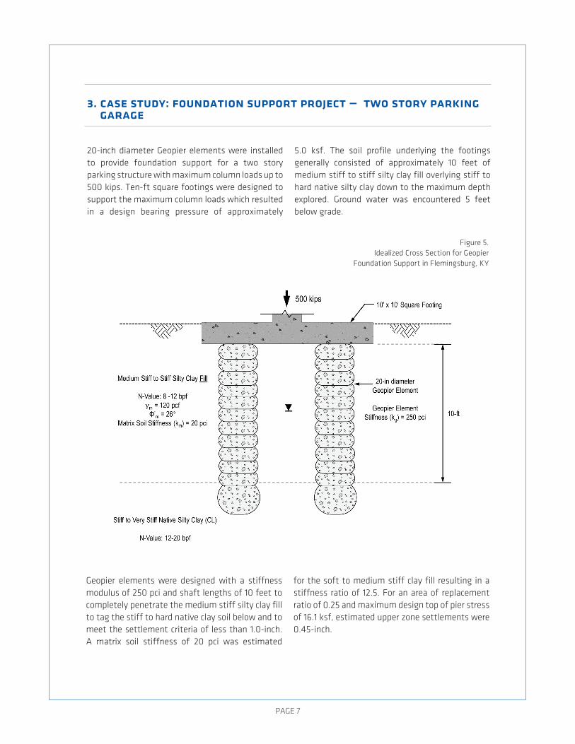
20-inch diameter Geopier elements were installed to provide foundation support for a two story parking structure with maximum column loads up to 500 kips. Ten-ft square footings were designed to support the maximum column loads which resulted in a design bearing pressure of approximately
5.0 ksf. The soil profile underlying the footings generally consisted of approximately 10 feet of medium stiff to stiff silty clay fill overlying stiff to hard native silty clay down to the maximum depth explored. Ground water was encountered 5 feet below grade.
Geopier elements were designed with a stiffness modulus of 250 pci and shaft lengths of 10 feet to completely penetrate the medium stiff silty clay fill to tag the stiff to hard native clay soil below and to meet the settlement criteria of less than 1.0-inch. a matrix soil stiffness of 20 pci was estimated
for the soft to medium stiff clay fill resulting in a stiffness ratio of 12.5. For an area of replacement ratio of 0.25 and maximum design top of pier stress of 16.1 ksf, estimated upper zone settlements were 0.45-inch.
garage
Figure 5. Idealized Cross Section for Geopier
Foundation Support in Flemingsburg, KY
PaGe 8
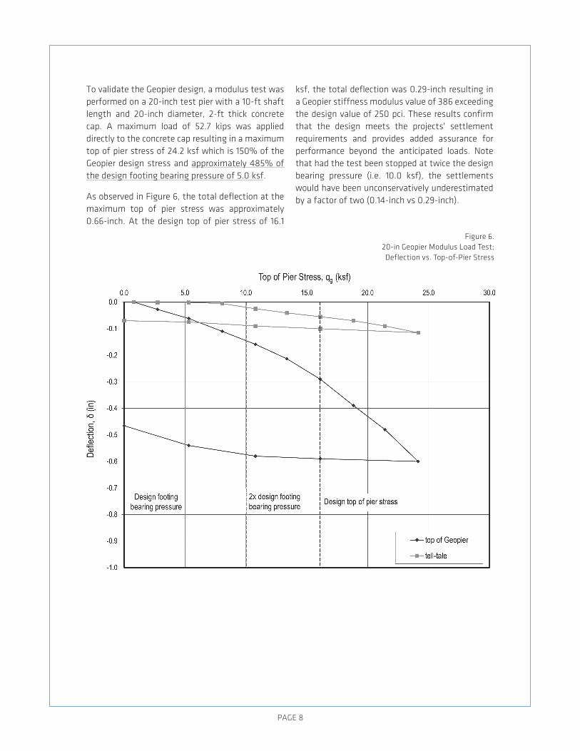
To validate the Geopier design, a modulus test was performed on a 20-inch test pier with a 10-ft shaft length and 20-inch diameter, 2-ft thick concrete cap. a maximum load of 52.7 kips was applied directly to the concrete cap resulting in a maximum top of pier stress of 24.2 ksf which is 150% of the Geopier design stress and approximately 485% of the design footing bearing pressure of 5.0 ksf.
as observed in Figure 6, the total deflection at the maximum top of pier stress was approximately 0.66-inch. at the design top of pier stress of 16.1
ksf, the total deflection was 0.29-inch resulting in a Geopier stiffness modulus value of 386 exceeding the design value of 250 pci. These results confirm that the design meets the projects' settlement requirements and provides added assurance for performance beyond the anticipated loads. note that had the test been stopped at twice the design bearing pressure (i.e. 10.0 ksf), the settlements would have been unconservatively underestimated by a factor of two (0.14-inch vs 0.29-inch).
Figure 6. 20-in Geopier Modulus load Test; Deflection vs. Top-of-Pier Stress
PaGe 9
appendix — modulus load testing schedule
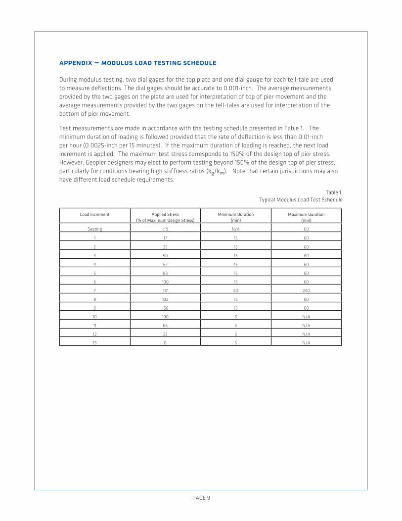
During modulus testing, two dial gages for the top plate and one dial gauge for each tell-tale are used to measure deflections. The dial gages should be accurate to 0.001-inch. The average measurements provided by the two gages on the plate are used for interpretation of top of pier movement and the average measurements provided by the two gages on the tell-tales are used for interpretation of the bottom of pier movement.
Test measurements are made in accordance with the testing schedule presented in Table 1. The minimum duration of loading is followed provided that the rate of deflection is less than 0.01-inch per hour (0.0025-inch per 15 minutes). If the maximum duration of loading is reached, the next load increment is applied. The maximum test stress corresponds to 150% of the design top of pier stress. However, Geopier designers may elect to perform testing beyond 150% of the design top of pier stress, particularly for conditions bearing high stiffness ratios (kg/km). note that certain jurisdictions may also have different load schedule requirements.
Load Increment Applied Stress(% of Maximum Design Stress)
Minimum Duration(min)
Maximum Duration(min)
Seating < 9 n/a 60
1 17 15 60
2 33 15 60
3 50 15 60
4 67 15 60
5 83 15 60
6 100 15 60
7 117 60 240
8 133 15 60
9 150 15 60
10 100 5 n/a
11 66 5 n/a
12 33 5 n/a
13 0 5 n/a
Table 1. Typical Modulus load Test Schedule

PaGe 10
references
lawton, e.C., Fox, n.S., and Handy, R.l., (1994). “Control of Settlement and uplift of Structures using Short aggregate Piers.” In-Situ Deep Soil Improvement, Proc. aSCe national Convention, atlanta, Georgia. 121-132
Terzaghi, K., Peck, R.B., and Mesri, G. (1996). Soil Mechanics in engineering Practice. Third edition. John Wiley & Sons, Inc., new York, nY.
acknowledgements
W. lake Carter, e.I.T.Kord J. Wissmann, Ph.D., P.e.

PaGe 11
symbols used
a = Gross footing area
ag = Footing area supported by Geopier elements
am = Footing area in contact with matrix soil
B = Width of footing
cϵ = Slope of the virgin or recompression curve
D = Bulb length (equal to Geopier element diameter)
ecomp = Composite elastic modulus of Geopier reinforced zone
eg = elastic modulus of Geopier element
elZ = elastic modulus of unreinforced lower zone soil
em = elastic modulus of matrix soil
HlZ = Thickness of lower zone
Hs = Geopier shaft length
H's = Depth of equivalent load transfer
Huz = Thickness of upper zone
IlZ = Stress influence factor for lower zone
Iuz = Stress influence factor for upper zone
kg = Stiffness modulus of the Geopier element
km = Stiffness modulus of the matrix soil
P0 = Initial vertical effective stress
Pf = Final vertical effective stress after the footing load has been applied
q = average Bearing pressure of footing
Q = Total downward force acting on the footing
Qg = Total upward resisting force in the Geopier elements
qg = Vertical stress applied to the Geopier element ("top of pier stress")
Qm = Total upward resisting force in the matrix soil
qm = Vertical stress applied to the matrix soil
Ra = area replacement ratio (ag/a)
Rs = Stiffness ratio (kg/km)
SlZ = Settlement in lower zone
STOT = Total settlement of footing
Suz = Settlement in upper zone
γm = unit weight of matrix soil
δtop = Deflection at top of pier
δTT = Deflection at tell-tale
фm = angle of internal friction of matrix soil

GEOPIER_TB_12_01.16
130 Harbour Place Drive, Suite 280, Davidson, nC 28036 800.371.7470 | [email protected] | [email protected]
©2016 Geopier Foundation Company, Inc. The Geopier® technology and brand names are protected under u.S. patents and trademarks listed at www.geopier.com/patents and other trademark applications and patents pending. Other foreign patents, patent applications, trademark registrations, and trademark applications also exist.
GeOPIeR IS GROunD IMPROVeMenT®
Work with engineers worldwide to solve your ground improvement challenges. For more information call 800-371-7470, email [email protected], or visit geopier.com.