technical memorandum 2.4.2 basic tunnel config r0... · · 2010-01-12... 4 2.2 laws and codes ......
TRANSCRIPT

Prepared by
for the California High-Speed Rail Authority
California High-Speed Train Project
TECHNICAL MEMORANDUM
Basic High-Speed Train Tunnel Configuration TM 2.4.2
Prepared by: Signed document on file___________ __29 June 2009 Jimmy Thompson Date
Checked by: Signed document on file___________ __15 July 2009_ Gary McClellan Date Approved by: Signed document on file___________ __30 July 2009_
Ken Jong, PE, Engineering Manager Date Released by: Signed document on file___________ __15 Oct 2009__
Anthony Daniels, Program Director Date
Revision Date Description 0 27 July 09 Initial Release, R0
Note: Signatures apply for the latest technical memorandum revision as noted above.

California High-Speed Train Project Basic HST Tunnel Configuration, R0
CALIFORNIA HIGH-SPEED RAIL AUTHORITY
This document has been prepared by Parsons Brinckerhoff for the California High-Speed Rail Authority and for application to the California High-Speed Train Project. Any use of this document for purposes other than this Project, or the specific portion of the Project stated in the document, shall be at the sole risk of the user, and without liability to PB for any losses or injuries arising for such use.

California High-Speed Train Project Basic HST Tunnel Configuration, R0
CALIFORNIA HIGH-SPEED RAIL AUTHORITY
Page i
System Level Technical and Integration Reviews The purpose of the review is to ensure: Technical consistency and appropriateness Check for interface issues and conflicts System level reviews are required for all technical memorandums. Technical Leads for each subsystem are responsible for completing the reviews in a timely manner and identifying appropriate senior staff to perform the review. Exemption to the System Level technical and integration review by any Subsystem must be approved by the Engineering Manager.
System Level Technical Reviews by Subsystem: Systems: Signed document on file___________ ___ 23 July 2009
Rick Schmedes Date Infrastructure: Signed document on file______________ 9 July 2009
John Chirco Date Operations: Signed document on file___________ ___ 17 July 2009
Paul Mosier Date Maintenance: Signed document on file___________ ___ 17 July 2009
Paul Mosier Date Rolling Stock: Signed document on file___________ ___ 10 July 2009
Frank Banko Date
Note: Signatures apply for the technical memorandum revision corresponding to revision number in header and as noted on cover.

California High-Speed Train Project Basic HST Tunnel Configuration, R0
CALIFORNIA HIGH-SPEED RAIL AUTHORITY
Page ii
TABLE OF CONTENTS
ABSTRACT.....................................................................................................................1
1.0 INTRODUCTION ..................................................................................................2
1.1 PURPOSE OF TECHNICAL MEMORANDUM .............................................................................2 1.2 STATEMENT OF TECHNICAL ISSUE .......................................................................................2
1.2.1 Definition of Terms .............................................................................................2 1.2.2 Units...................................................................................................................3
2.0 DEFINITION OF TECHNICAL TOPIC ..................................................................4
2.1 GENERAL .........................................................................................................................4 2.2 LAWS AND CODES .............................................................................................................4 2.3 BASIC TUNNEL CONFIGURATION .........................................................................................4
2.3.1 Bored Tunnels....................................................................................................5 2.3.2 Cut-and-Cover Tunnels ......................................................................................5 2.3.3 Interfaces ...........................................................................................................5 2.3.4 Finished Shape and Method of Construction.......................................................5
2.4 ROLLING STOCK, STATIC GAUGE, DYNAMIC ENVELOPE AND EQUIPMENT ................................6 2.4.1 Rolling Stock ......................................................................................................6 2.4.2 Static Gauge ......................................................................................................6 2.4.3 Dynamic Envelope..............................................................................................6 2.4.4 Pantograph and Catenary Electrical and Mechanical Envelopes .........................6 2.4.5 Fixed Equipment Envelope.................................................................................6 2.4.6 Continuous Equipment .......................................................................................7 2.4.7 Intermittent Equipment........................................................................................7 2.4.8 Excluded Equipment...........................................................................................7
2.5 OTHER TUNNEL SIZE PARAMETERS.....................................................................................8 2.5.1 Invert..................................................................................................................8 2.5.2 Trackform...........................................................................................................8 2.5.3 Escape Walkway ................................................................................................8 2.5.4 Construction Tolerances.....................................................................................9
2.6 POLICY CONSIDERATIONS ..................................................................................................9
3.0 ANALYSIS AND ASSESSMENT .......................................................................10
3.1 VENTILATION, TRANSIENT AIR PRESSURES, AERODYNAMICS AND TEMPERATURE ...................10 3.1.1 Transient Air Pressures ....................................................................................10 3.1.2 Effect of Transient Air Pressures on People......................................................12 3.1.3 Aerodynamics ..................................................................................................13 3.1.4 Temperature.....................................................................................................14
3.2 TUNNEL DIMENSIONS BASED ON MEDICAL HEALTH CRITERIA ................................................14 3.2.1 Calculation of Free Tunnel Cross Sectional Area ..............................................14 3.2.2 Tunnel Geometry..............................................................................................16
3.3 MITIGATION MEASURES ....................................................................................................17
4.0 CONCLUSIONS AND RECOMMENDATIONS ..................................................18
5.0 SOURCE INFORMATION AND REFERENCES ................................................19

California High-Speed Train Project Basic HST Tunnel Configuration, R0
CALIFORNIA HIGH-SPEED RAIL AUTHORITY
Page iii
6.0 DESIGN MANUAL CRITERIA............................................................................20
6.1 BASIC TUNNEL CONFIGURATION .......................................................................................20 6.1.1 General ............................................................................................................20 6.1.2 Tunnel Cross Section .......................................................................................20 6.1.3 Tunnel Geometry..............................................................................................21
APPENDIX A – REPRESENTATIVE TRAIN PROFILES
APPENDIX B – MEDICAL HEALTH LIMITS CALCULATIONS
APPENDIX C – MEDICAL HEALTH LIMITS BLOCKAGE RATIO CURVES
APPENDIX D – BASIC TUNNEL CROSS SECTIONS

California High-Speed Train Project Basic HST Tunnel Configuration, R0
CALIFORNIA HIGH-SPEED RAIL AUTHORITY
Page 1
ABSTRACT This Technical Memorandum establishes approximate finished dimensions for bored and cut-and-cover tunnels in which high-speed passenger trains run exclusively, for use during 15% Design level in determining alignment corridors and right-of-way requirements, and in the development of cost estimates. The basic tunnel configuration is assumed to be twin, single-track tunnels and the rolling stock is assumed to be sealed. Tunnel shapes are circular (TBM driven) for bored tunnels and rectangular for cut-and-cover tunnels. All tunnels are assumed watertight.
The basic tunnel configurations incorporate train profiles, static gauge, kinematic envelope, fixed equipment envelope, tangent and superelevated track, construction tolerances, escape walkways, pantograph catenary and support structure, ballasted or fixed (slab) track, and drainage. These items are at an early stage of design and are subject to refinements which may affect finished tunnel dimensions. Wherever possible, allowances have been made to accommodate future changes for those items that have not yet been defined such as fixed equipment including cables and pipes.
The basic tunnel dimensions are established to comply with the European Technical Specifications for Interoperability (TSI) requirements for a 10 kPa (1.45 psi) maximum pressure variation in tunnels and underground structures for trains complying with high-speed rolling stock criteria at a maximum operating speed of 220 mph. The purpose of limiting the pressure changes is to mitigate adverse health effects or discomfort to passengers and workers; these criteria are known as medical health criteria.
A preliminary assessment of the required free tunnel cross sectional areas for different train speeds and tunnel lengths are established from data provided in UIC 779-11R “Determination of railway tunnel cross sectional areas on the basis of aerodynamic considerations.” The UIC code is concerned only with the aerodynamic effects on passengers and workers hence represent the medical health criteria. Finished tunnel dimensions are established based on the required free tunnel cross sectional areas. The medical health criteria represent the critical case (largest tunnel size) for short tunnels.
As tunnel length increases, medical health criteria become less critical and the effects of aerodynamic drag on the trains in the tunnels increases significantly compared with open track operation. Heat generated from the aerodynamic drag, air conditioning of the trains, and systems, builds up in the tunnels. These effects can be mitigated by increasing the tunnel size, cooling the tunnels, reducing the aerodynamic drag of the trains, and increasing the power available to the trains. A qualitative discussion of these complex issues is included in this TM. Quantitative analysis will be carried out during subsequent design phases.
The following factors may influence the finished tunnel dimensions and will be studied further during detailed design:
Emergency ventilation requirements Portals, junctions, interfaces and transitions between bored tunnels, cut-and-cover tunnels
and other structures Various measures can be used to mitigate these effects, including pressure relief ducts between tunnels and airshafts between the tunnels and ground surface. These mitigation measures will be addressed along with a quantitative analysis of aerodynamic effects in future studies.

California High-Speed Train Project Basic HST Tunnel Configuration, R0
CALIFORNIA HIGH-SPEED RAIL AUTHORITY
Page 20
6.0 DESIGN MANUAL CRITERIA 6.1 BASIC TUNNEL CONFIGURATION 6.1.1 General
This document establishes approximate finished dimensions for bored and cut-and-cover tunnels in which high-speed passenger trains run exclusively, for use during 15% Design level in determining alignment corridors and right-of-way requirements, and in the development of cost estimates. The basic tunnel configuration is assumed to be twin, single-track tunnels and the rolling stock is assumed to be sealed. Tunnel shapes are circular (assumed TBM driven) for bored tunnels and rectangular for cut-and-cover tunnels. All tunnels are assumed watertight.
The basic tunnel dimensions are established to comply with the European Technical Specifications for Interoperability (TSI) requirements for a 10 kPa maximum pressure variation in tunnels and underground structures for any train complying with high-speed rolling stock criteria at the maximum permitted operating speed of 220 mph. The purpose of limiting the pressure changes is to ensure no adverse health effects or discomfort to passengers and workers; these criteria are known as medical health criteria.
A preliminary assessment of the required free tunnel cross sectional areas for different train speeds and tunnel lengths were established from data provided in UIC 779-11R “Determination of railway tunnel cross sectional areas on the basis of aerodynamic considerations.” Finished tunnel dimensions are established based on the required free tunnel cross sectional areas. Detailed numerical modeling is required during advanced design and recommendations for numerical modeling are provided in the UIC code. It should be clarified that the UIC code is concerned only with the aerodynamic effects on passengers and workers hence the medical health criterion.
Various measures can be used to mitigate these effects, including pressure relief ducts between tunnels and airshafts between the tunnels and ground surface. These mitigation measures will be studied further as required to ensure an efficient and optimum tunnel configuration during advanced design.
6.1.2 Tunnel Cross Section 6.1.2.1 Determination of Train Cross Sectional Area
The Shinkansen bi-level rolling stock has the largest train cross sectional area of the high-speed trains currently contemplated and was used to determine Blockage Ratios from the UIC guideline. It is noted that the calculation is sensitive to the train cross sectional area. Accordingly, calculations that are related to the cross section area of the vehicle should be verified following selection of the high-speed rolling stock.
6.1.2.2 Calculation of Blockage Ratio
The Blockage Ratio, Btu, is determined from UIC 779-11R, Appendix F.
Tunnel free cross sectional area = Train cross sectional area / Blockage Ratio
Where:
Train cross sectional area is calculated as the projected frontal area above mid axle of the leading vehicle (see UIC 779-11 R Appendix E), and
The Blockage Ratio is obtained from the limit curves in UIC 779-11 R Appendix F, Figure 4.
The curves in these figures were generated using computer software program Sealtun Version 2.

California High-Speed Train Project Basic HST Tunnel Configuration, R0
CALIFORNIA HIGH-SPEED RAIL AUTHORITY
Page 21
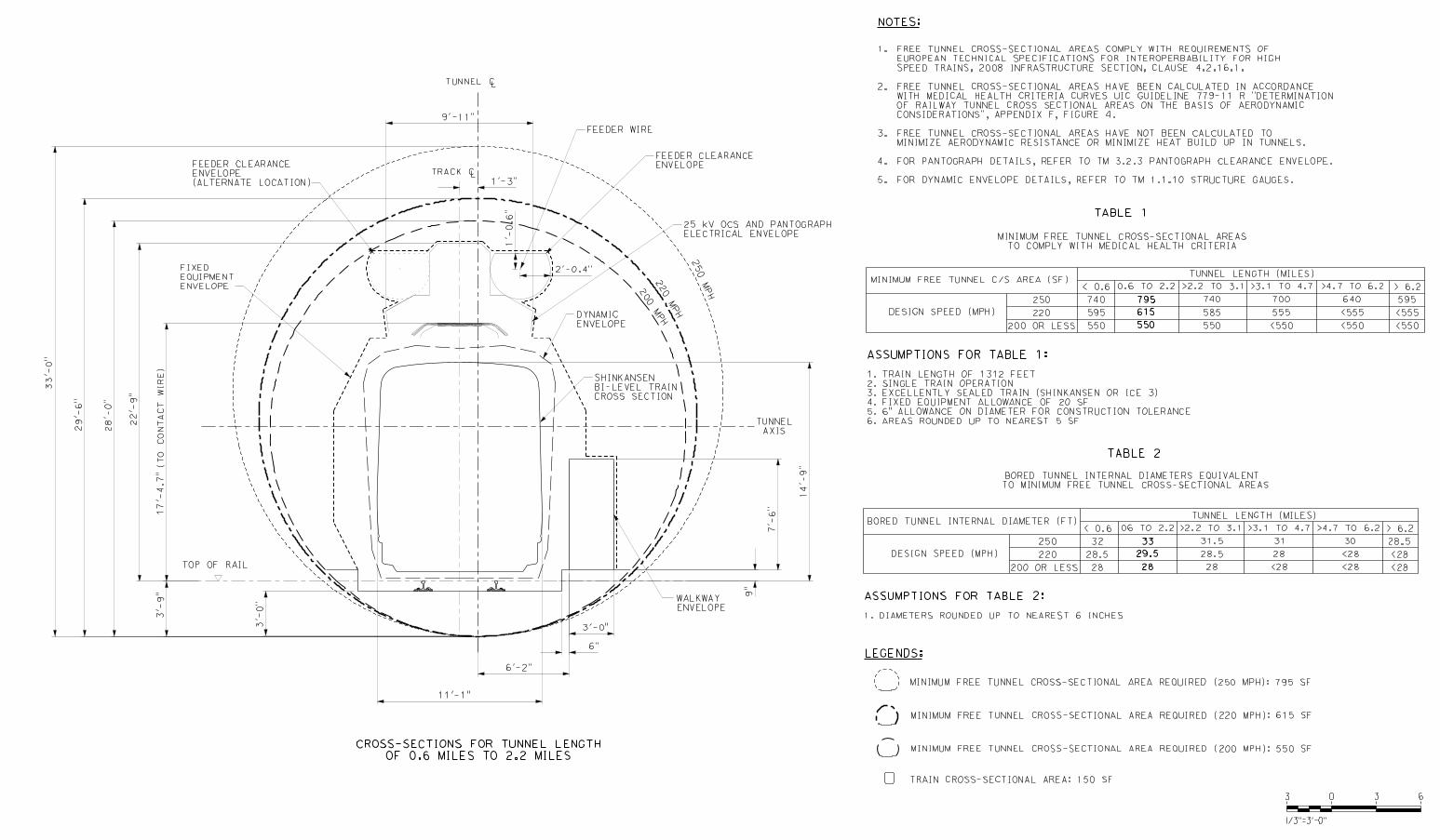
For single train operation and a train length of 1312 ft (400 m), Figure 4 of UIC 779-11 R Appendix F is used.
The Blockage Ratio can be calculated for a given tunnel length (Ltu) ranging between 0.6 miles (1 km) and 2.2 miles (10 km), and train speeds (Vtr) of 200 mph (330 kph), 220 mph (350 kph) and 250 mph (400 kph).
The critical case i.e., largest free tunnel cross sectional area is when the Blockage Ratio is smallest for a given train speed. From the UIC curves, this critical case is between tunnel lengths of 0.6 miles (1km) and 2.2 miles (10 km) for train speeds of 250 mph (400 kph) 220 mph (350 kph) and 200 mph (330 kph) respectively. Below and above this tunnel length, the Blockage Ratio increases i.e., free tunnel cross-sectional area decreases.
For comparison, the critical case for 325 ft (100 m) trains traveling at any speed is at a tunnel length of 0.3 miles. i.e., if shorter trains are used, the critical case will be at a shorter tunnel length.
6.1.2.3 Calculation of Free Tunnel Cross Section Area
The free tunnel cross sectional area have been calculated for the following tunnel lengths for train speeds of 250 mph (400 kph), 220 mph (350 kph) and 200 mph (330 kph).
Less than 0.6 miles (1 km) 0.6 miles to 2.2 miles (1 km to 3.5 km) Greater than 2.2 miles to 3.1 miles (3.5 km to 5 km) Greater than 3.1 miles to 4.7 miles (5 km to 7.5 km) Greater than 4.7 miles to 6.2 miles (7.5 km to 10 km) Greater than 6.2 miles (10 km)
An allowance of 20 sf has been added to each of these free cross sectional areas to account for fixed equipment.
6.1.3 Tunnel Geometry 6.1.3.1 Bored Tunnel
The finished bored tunnel cross sectional area is the sum of the following areas and additional allowances:
Free tunnel cross sectional area as calculated and required by the medical health criteria 20 sf for fixed equipment 6-inch allowance on diameter for construction tolerance (tunnel built too low or too small) 3-foot depth of invert concrete An escape walkway at track level (slightly raised above invert level).
The critical case is at tunnel lengths of 0.6 miles to 2.2 miles and requires a finished tunnel diameter of 29’-6”.
For tunnels shorter than 0.6 miles and tunnels longer than 2.2 miles, tunnel diameters can be reduced for a train speed of 220 mph while still complying with medical health criteria.
Aerodynamic performance of the train, power consumption and heat generated must be considered and may represent the critical case for longer tunnels.

California High-Speed Train Project Basic HST Tunnel Configuration, R0
CALIFORNIA HIGH-SPEED RAIL AUTHORITY
Page 22
6.1.3.2 Cut-and-Cover Tunnel
The finished cut-and-cover cross sectional area is the sum of the following areas and additional allowances:
Free tunnel cross sectional area as calculated above and required by the medical health criteria.
20 sf for fixed equipment. 12-inch vertical construction tolerance (assuming slurry wall construction). 4-inch horizontal tolerance for stepped invert concrete for adjustments to track grade Average 3’-2” depth of invert concrete. An escape walkway at track level (slightly raised above invert level).
The structure gauge has a minimum fixed width of 21’-9”. A width of 23’-9” has been assumed for the purposes of calculating tunnel heights at different design speeds. These heights have been shown on the directive drawings for the critical case for tunnel lengths of 0.6 miles to 2.2 miles.
The required free tunnel cross sectional areas and design speeds are tabulated on the directive drawings. Designers determine an appropriate width and height to suit alignment corridor and right-of-way constraints and determine efficient structural spans for the depth of construction required.
The actual free tunnel cross-sectional area was measured and adjusted to correspond with the calculated free cross sectional area from the spreadsheet. The adjusted finished tunnel height was rounded up to the nearest six inches.
Basic tunnel cross sections are presented in Appendix D.

California High-Speed Train Project Basic HST Tunnel Configuration, R0
CALIFORNIA HIGH-SPEED RAIL AUTHORITY
APPENDIX D – BASIC TUNNEL CROSS SECTIONS