technical assistance consultant’s report - adb.org · is coincident with ql 45 for approximately...
TRANSCRIPT

Technical Assistance Consultant’s Report
This consultant’s report does not necessarily reflect the views of ADB or the Governments concerned, and ADB and the Governments cannot be held liable for its contents. All the views expressed herein may not be incorporated into the proposed project’s design.
Project Number: 41444-01 December 2010
Regional: Preparing the Second Northern Greater Mekong Subregion Transport Network Improvement Project (Financed by the Japan Special Fund)
Prepared by Dainichi Consultant Inc, Japan
In association with Denac Associates, Canada Lao Consulting Group, Lao PDR Hanoi Design and Consulting Joint Stock Company Viet Nam
For the Ministry of Public Works and Transport, Lao PDR and the Ministry of Transport, Viet Nam

SSSuuuppppppllleeemmmeeennntttaaarrryyy AAAppppppeeennndddiiixxxVol.1 Road Engineering Vol.2 Bridge Engineering
Dsc00088.jpg Dsc00088.jpg
COSO/80-177
DAINICHI CONSULTANT INC, Japan
In association with
DENAC ASSOCIATES, CANADA
LAO CONSULTING GROUP, Lao PDR
FFIINNAALL RREEPPOORRTT

Preparation of Second Northern GMS Transport Network Improvement Project
ADB TA 6478 REG Preparing the Second Northern Greater Mekong Subregion Transport Network Improvement Project
Supplementary Appendix Volume1
Road Engineering Report
July 2010
DAINICHI CONSULTANT INC, in association
DENAC ASSOCIATES, CANADA
LAO CONSULTING GROUP, Lao PDR
Hanoi Design and Consulting Joint Stock Company, Vietnam


Preparation of Second Northern GMS Transport Network Improvement Project
i
Table of content
Part A - Vietnam A1. Project Road.......................................................................................................................... 1 A1.1 General .................................................................................................................................1 A1.2 Road engineering surveys.................................................................................................1 A1.3 Project engineering documentation..................................................................................2 A2.0 QL 217 Characteristics.........................................................................................................3 A2.1 Road management and maintenance ...............................................................................3 A2.1.1 Management and operations .......................................................................................3
A2.1.2 Road maintenance funding ..........................................................................................4
A2.1.3 Road management and maintenance systems and initiatives .....................................5
A2.2 Road characteristics ..........................................................................................................6 A2.2.1 Project road description ...............................................................................................6
A2.2.2 Road alignment ............................................................................................................8
A2.2.3 Existing pavement characteristics.................................................................................9
A2.2.4 Wet and flooded sections.............................................................................................9
A2.2.5 Slope stability ...............................................................................................................10
A2.2.6 Traffic ...........................................................................................................................13
A2.2.7 Accident data ...............................................................................................................14
A2.2.8 Culverts ........................................................................................................................17
A2.2.9 Axle load data ..............................................................................................................18
A2.2.10 Rural Roads ...............................................................................................................19
A3.0 Road alignment...................................................................................................................20 A3.1 General ................................................................................................................................20 A3.2 Road alignment geometry..................................................................................................21
A3.2.1 Horizontal alignment considerations ............................................................................21
A3.2.2 Vertical alignment consideration ..................................................................................21 A3.3 Proposed Road Cross Section Details .............................................................................23 A3.3.1 Cross section details ...................................................................................................23
A3.3.2 Curve Widening............................................................................................................25
A3.4 Road intersections .............................................................................................................25 A3.5 Possible Alignment Improvements....................................................................................26 3.6 Road By-pass Sections .........................................................................................................26 A3.6.1 General ........................................................................................................................26
A3.6.2 Intersection of QL217 with QL1....................................................................................27
A3.6.3 Possible Town Bypasses .............................................................................................28 A4.0 Drainage structures and weighbridge ..............................................................................30
Preparation of Second Northern GMS Transport Network Improvement Project
ii
A4.1 General ..................................................................................................................................30 A4.2 Pipe and Box/Slab Culverts ...............................................................................................30 A4.3 Weighbridge ........................................................................................................................30 A5.0 Pavement Design................................................................................................................32 A5.1 General ................................................................................................................................32 A5.2 Pavement and materials investigation..............................................................................32 A5.3 Pavement design ................................................................................................................33 A6.0 Cost Estimates ....................................................................................................................35 A6.1 General .................................................................................................................................35 A6.2 Assumption made in the Cost Estimates .........................................................................35 A6.2.1 General ........................................................................................................................35
A6.2.2 Construction unit rates .................................................................................................35
A6.2.3 Proposed Construction Contracts ................................................................................36
A7.0 Recommendation ................................................................................................................42 Annex A of Part A Road Standards ............................................................................................43 Annex B of Part A Road Inventory and Condition......................................................................46 Annex C of Part A Pavement Analysis ........................................................................................48 Annex D of Part A Institutional ...................................................................................................63 Annex E of Part A Rural Roads ...................................................................................................68
Part B - Lao PDR B1.0 Project Roads......................................................................................................................1 B1.1 General .................................................................................................................................1 B1.2 Road Engineering Surveys ................................................................................................1 B1.3 Project documentation........................................................................................................2 B2.0 Project Road Characteristics.............................................................................................3 B2.1 Road Management and Maintenance................................................................................3
B2.1.1 Management and Operations.......................................................................................3
B2.1.2 Road maintenance funding ..........................................................................................3
B2.1.3 Road management and maintenance systems and initiatives .....................................4
B2.2 Road characteristics ..........................................................................................................5 B2.2.1 Project Road Description .............................................................................................5
B2.2.2 Road Alignment............................................................................................................8
B2.2.3 Existing Pavement Characteristics................................................................................8
B2.2.4 Wet and flooded sections.............................................................................................9
B2.2.5 Slope stability .............................................................................................................10

Preparation of Second Northern GMS Transport Network Improvement Project
iii
B2.2.6 Traffic ...........................................................................................................................10
B2.2.7 Accident Data...............................................................................................................14
B2.2.8 Culverts .......................................................................................................................17
B2.2.9 Axle load data ..............................................................................................................17
B2.2.10 Rural Roads ...............................................................................................................19
B3.0 Road Alignment ..................................................................................................................21 B3.1 General ................................................................................................................................21 B3.2 Road alignment geometry..................................................................................................21
B3.2.1 Horizontal alignment considerations ............................................................................21
B3.2.2 Vertical alignment considerations ................................................................................22
B3.3 Proposed Road Cross Section Details .............................................................................23 B3.3.1 Proposed Upgrading of Lao PDR Roads (R6, R6A and R6B) .....................................23
B3.3.2 Proposed Alignment Improvements of Lao Roads (R6 and R1D) ..............................24
B3.3.3 Curve Widening............................................................................................................24
B3.3.4 Supperelevation ...........................................................................................................24
B4.0 Drainage Structures and Weighbridge .............................................................................26 B4.1 General ..................................................................................................................................26 B4.2 Pipe and Box/Slab Culverts ...............................................................................................26 B4.3 Weighbridge ........................................................................................................................27 B5.0 Pavement Design................................................................................................................28 B5.1 General ................................................................................................................................28 B5.2 Key Assumptions ...............................................................................................................28 B6.0 Cost Estimates ....................................................................................................................30 B6.1 General .................................................................................................................................30 B6.2 Assumption made in the Cost Estimates .........................................................................30 B6.3 Construction unit rates ......................................................................................................30 B6.4 Proposed Construction Contracts ....................................................................................31 Annex A of Part B Engineering Review of Road 6A Design....................................................38 Annex B of Part B Proposed Road Standards..........................................................................41 Annex C of Part B ........................................................................................................................43 Annex D of Part B RURAL ROADS ...........................................................................................45 Annex E of Part B Pavement Analysis .......................................................................................53 Annex F of Part B Institutional Issues ........................................................................................69

Preparation of Second Northern GMS Transport Network Improvement Project
iv
ABBREVIATIONS
ADB – Asian Development Bank
DoR – Department of Roads (Laos)
DPWT – Provincial Department of Public Works and Transport (Lao PDR)
EIA – Environmental impact assessment
EIRR – Economic internal rate of return
GDP – Gross domestic product
GIS – Geographical information system
GOL – Government of Laos
GOK – Government of Vietnam
HDM – Highway development and management model
HIV – Human immunodeficiency virus
IEE – Initial environmental examination
KfW – KfW Bankengruppe
LRD – Local Roads Department
NGO – Nongovernmental organization
NPV – Net present value
MPWT – Ministry of Public Works and Transport
PDoT – Provincial Department of Transport
PIR – Poverty impact ratio
PMU – Project management unit
PRC – Peoples Republic of China
PRoMMS – Provincial Road Maintenance Management System
RAD – Road Administration Department (Laos)
REA – Rapid environmental assessment
RMS – Road management system
TA – Technical assistance
TEDI – Transport Engineering Design Institute
TOR – Terms of reference
STI – Sexually transmitted infection
VOC – Vehicle operating costs

Preparation of Second Northern GMS Transport Network Improvement Project
A 1
Part A - Vietnam
A1. Project Road
A1.1 General 1. This report makes up one volume of the Supplementary Appendices to the main project report. Some of the analysis presented in Part A of this volume (Volume1) is based on data and analysis presented in other volumes. These volumes are listed in A1.3 below.
2. The project road in Vietnam is part of the North Eastern economic corridor for the Greater Mekong Sub-region (GMS) Economic Cooperation Program. The project road length is approximately 195 km. In order to maximize the Project benefits to the people within the road catchment area, the project will also prioritize approximately 100 km of rural access roads for improvement, linking the corridor to the hinterland.
3. The origin of QL217 is Do Len, Km 301.5 on NH1A, in Ha Trung District, Thanh Hoa province. The existing alignment goes through the towns of Vinh Loc (where the road is coincident with QL 45 for approximately 3.3 kilometers) and Cam Thuy where it coincident with the Ho Chi Minh Highway (HCMH) for a distance of approximately 1.0 Km. West of HCMH the road presently passes through Cam Thuy and a length of strip of urban development followed by road sections that pass through rural and semi rural settings as well as the town of Canh Nang. At Km104.7 the project road enters the town of Dong Tam and intersects with QL15A which it follows to Km 107.2. West of this point the road moves from the flat to rolling terrain to go through steeper terrain found in the valleys the road follows through to Na Mao. QL217 passes through Quan Son and a number of small villages and settlements up to the Lao border at Na Meo.
4. Road sections not included in the upgrading project are as follows:
• 1.0 km of HCM highway section at Cam Thuy (Km 56 .4 to 57.5 on the QL217) - there will be some improvements of the highway at the intersections; and
• Km 57.5 to Km 58.3 - resurfacing with AC to be considered.
A1.2 Road engineering surveys 5. Surveys carried out during the project were as follows:
• GPS centerline survey - used to define/show the general alignment characteristics of the project road. Refer to Supplementary Appendix Volume 11 Drawing for the road plan and profile;
• Road inventory and conditions surveys - provided information on the physical road characteristics, key condition indicators, location and extent of towns, drainage details, terrain type and cross sections details (height of cut/fill, slope, etc). Data was used to characterize the road condition, identify location of cross section changes, and to calculate earthworks, and drainage structure replacements, etc. Annex B of Part A Road Inventory and Condition, includes a sample road condition and inventory sheet. Results are summarized in Table A2.2.2 – QL 217 Road characteristics, with other road condition data;
• Work needs field assessments - a field assessment was carried out to identify the extent and location ( side) of road widening and upgrading;
• Traffic surveys - classified counts and origin/destination surveys, were conducted at 5 locations. Details are presented in Supplementary Appendix Volume 5;

Preparation of Second Northern GMS Transport Network Improvement Project
A 2
• Roughness survey - measured using a calibrated roughness meter. Data was used to assist in characterizing the road and provide data for the HDM4 analysis. Results are summarized in Table A2.2.2 with other road condition data;
• Deflection surveys at representative road sections - surveys were carried out as a complimentary method to test pit/sample laboratory testing and DCP, even though visual assessments indicated that many pavement sections are definitely in need of rehabilitation. Results are summarized in Annex C of Part A;
• Test pits and material source investigations and laboratory surveys - 20 test pits and 60 DCP measurements were made (20 at the site of the test pit). This data provided details of the existing pavement structure and also subgrade conditions (density, moisture content and variations in strength/densities along the road and also with depth). Results are summarized in Annex C of Part A; and
• Road safety audits - intended to identify road safety issues along the road. Details are presented in Supplementary Appendix Volume 9.
6. The above list excludes the bridge, social, environmental and resettlement surveys which were carried out and reported in the individual Supplementary Appendix volumes.
A1.3 Project engineering documentation 7. The project engineering reporting is spread across the following three supplementary appendix volumes:
Volume 1 Road engineering (including pavements and cost estimates),
Volume 2 Bridge engineering,
Volume 9 Road Safety Audit,
Volume 10 Procurement Documents, and
Volume 11 Drawings
The bidding documents consist of the following:
· Request for Bid;
· General and specific conditions of contract;
· Specification (standard and special); and
· Bill of quantities;
The drawings consist of the following:
· Plan and profile of the existing alignment with locations of culverts and bridges indicated;
· Tables showing location and details of bridges and culverts;
· Table showing offsets from the existing to the proposed new alignment;
· Table showing location of curves improvements;
· Detailed drawings of intersections, bridges, etc
Preparation of Second Northern GMS Transport Network Improvement Project
A 3
A2.0 QL217 Characteristics
A2.1 Road management and maintenance
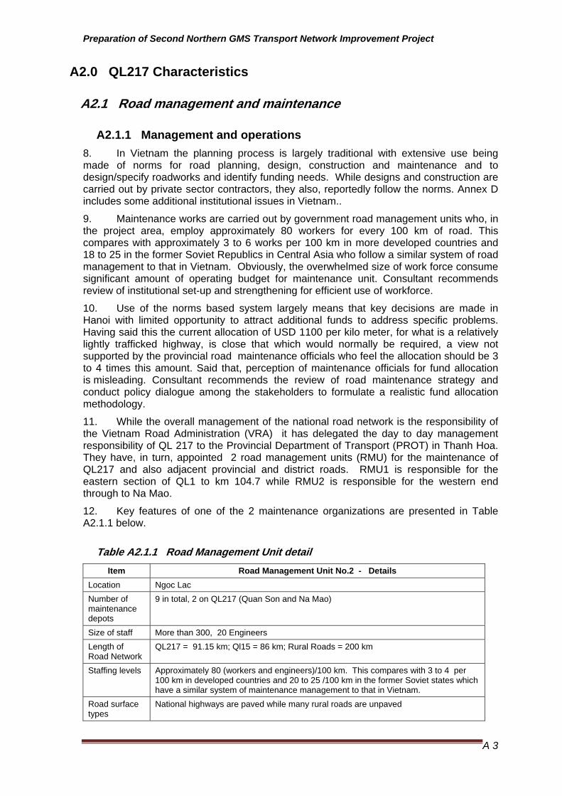
A2.1.1 Management and operations 8. In Vietnam the planning process is largely traditional with extensive use being made of norms for road planning, design, construction and maintenance and to design/specify roadworks and identify funding needs. While designs and construction are carried out by private sector contractors, they also, reportedly follow the norms. Annex D includes some additional institutional issues in Vietnam..
9. Maintenance works are carried out by government road management units who, in the project area, employ approximately 80 workers for every 100 km of road. This compares with approximately 3 to 6 works per 100 km in more developed countries and 18 to 25 in the former Soviet Republics in Central Asia who follow a similar system of road management to that in Vietnam. Obviously, the overwhelmed size of work force consume significant amount of operating budget for maintenance unit. Consultant recommends review of institutional set-up and strengthening for efficient use of workforce.
10. Use of the norms based system largely means that key decisions are made in Hanoi with limited opportunity to attract additional funds to address specific problems. Having said this the current allocation of USD 1100 per kilo meter, for what is a relatively lightly trafficked highway, is close that which would normally be required, a view not supported by the provincial road maintenance officials who feel the allocation should be 3 to 4 times this amount. Said that, perception of maintenance officials for fund allocation is misleading. Consultant recommends the review of road maintenance strategy and conduct policy dialogue among the stakeholders to formulate a realistic fund allocation methodology.
11. While the overall management of the national road network is the responsibility of the Vietnam Road Administration (VRA) it has delegated the day to day management responsibility of QL 217 to the Provincial Department of Transport (PROT) in Thanh Hoa. They have, in turn, appointed 2 road management units (RMU) for the maintenance of QL217 and also adjacent provincial and district roads. RMU1 is responsible for the eastern section of QL1 to km 104.7 while RMU2 is responsible for the western end through to Na Mao.
12. Key features of one of the 2 maintenance organizations are presented in Table A2.1.1 below.
Table A2.1.1 Road Management Unit detail Item Road Management Unit No.2 - Details
Location Ngoc Lac Number of maintenance depots
9 in total, 2 on QL217 (Quan Son and Na Mao)
Size of staff More than 300, 20 Engineers Length of Road Network
QL217 = 91.15 km; Ql15 = 86 km; Rural Roads = 200 km
Staffing levels Approximately 80 (workers and engineers)/100 km. This compares with 3 to 4 per 100 km in developed countries and 20 to 25 /100 km in the former Soviet states which have a similar system of maintenance management to that in Vietnam.
Road surface types
National highways are paved while many rural roads are unpaved

Preparation of Second Northern GMS Transport Network Improvement Project
A 4
Item Road Management Unit No.2 - Details Primary responsibilities
Routine Maintenance and repairs; Emergency maintenance;
Traffic counts;
Annual Inspections and work plan preparation.
Work need identification and planning
Works are identified by the RMU who submit the work to the PDOT, who then submit to VRA. The PDOT normally review the submissions and add their ownassessment of needs, especially where the requests are additional to those indicated by norms.
Major maintenance issues
Slips and flood damage during the wet season. Require the RMU to hire equipment in bad years.
Maintenance costs
Are based on norms which identify the resources required for each task. This means that the approved work quantities are normally less than needed.
QL217 road section (length)
Km 104.65 to 195.8 (bridge at border)
Equipment Fleet Ownership
RMU1 is said to have purchased the equipment, although this was not certain. Deputy Director made a point of asking for equipment to be provided under the project. It is suspect that RMU2 received funds from the MoT to purchase the equipment, most of which is less than 4 years old. Equipment is from Japan, Russia and China/Vietnam.
Equipment Fleet
2 Excavators; 2 bulldozers, 4 dump trucks; 1 bitumen sprayer; 5 rollers and a quantity of other equipment
Use of external resources
Equipment, such as excavators are hired when there is a need to clear slips.
Funding 2009 Current funding levels are equal to VND 19 million/km (USD 1100/km) for routine and emergency maintenance/repairs. This is a decrease of 5% from 2008.
Required Funding
The RMU felt that the required funding was VND 100 million/km.
Rehabilitation and Construction Works Design
While RMU may be involved in the initial identification of rehabilitation, they are not involved in either the design or construction phase. The work is organized by the Thanh Hoa PDOT who engages consultants for the design phase and contractors for construction. Both are reported to be tendered.
Future Plans Thanh Hoa Peoples Committee is promoting a change in the structure of the Road Management Unit, namely making them Joint Stock Companies who could then not be limited to routine/periodic and emergency works. They would then be able to compete with the private sector.
Additional Comments
It was noted that there were no graders, even though there were approximately 120 km of gravel roads. There appear to be a limited range of treatments and there is scope for introducing new methods/approaches. Rapid maintenance operations conduces lowering costs and reducing the impact on road users.
There are plans to restructure the PMU as a joint stock company (JSC), which would allow it to tender for an win other work. This is a part of a national initiative which is reported to be only partly successful as the JSC continue to closely linked to their government clients.
Source: Prepared by Consultant based on Discussions with the RMU2
A2.1.2 Road maintenance funding 13. Road funds are provided by the Central Government for the maintenance works on national district and rural roads. The funds are funneled either through Regional Road Management Units (for National Highways) and the provincial authorities, principally the Provincial Department of Transport in the case of provincial, rural and some national

Preparation of Second Northern GMS Transport Network Improvement Project
A 5
highways, as is the case with the project road. Road funding levels are as shown in Table A2.1.1 below.
14. It was reported that the GoV has been able to increase road maintenance funding by approximately 7% per annual over recent years, although as can be see from the national funding allocations reported in Table A2.1.2 below, the annual rate of increase between 2006 and 2009 is approximately 14%.
Table A2.1.2 Road maintenance funding
Budgets (VND) Road length (km) 2006 2007 2008 2009
National Maintenance Budget (billions) 16848 1371 TBA 1903 2018 QL 217 (billion) 195.8 TBA TBA 4 3.7
Source: VRA, RMU and PDOT Above values are for routine maintenance, and some limited periodic maintenance TBA: To Be Advised
A2.1.3 Road management and maintenance systems and initiatives
Road information systems 15. Discussions with engineers at the provincial level and also with VRA indicate that there is a lack of a comprehensive road information system, and that past efforts to establish systems have only partially been successful with the result that there is presently minimal use being made of the Road Management Information System (RIMS) (established in 2005) and the RoSy system that preceded it. It has been reported that the data in the system is now dated, the systems are not working well (reason not clear) and the resources (equipment, trained people and funds) required to run the data hungry system (according the VRA) are inadequate.
16. Maintenance funding distributions, carried out by the VRA, are based on norms and funding submissions which are submitted by the 4 Regional Road Management Units (RRMU) and the PDOTS who are responsible for national highways. As indicated earlier the extensive use of norms means that the needs of roads is not reflected in the funding allocations with most of the maintenance organizations saying that the levels were less than half that required.
17. The data systems at the provincial level are more basic with extensive use being made of spreadsheets.
Contracted road maintenance 18. An initiative being developed as part of the Road Network Improvement Project (RNIP) will see the first performance based contract (PBC) maintenance contracts being tended in July with contracts being let in February 2010. The initiative is to pilot the concept by letting 3 contracts with lengths of 80 to 140 km on roads QL1 and QL10 and covering a total distance of 300 km. The effectiveness of the contract in delivering improvement improved maintenance in a cost effective way will however be difficult to judge as the scope of the contracts have been modified to now include significant pavement reconstruction and overlay works in the contracts, increasing the budget to USD 30 million for 300 km over 3 years, form the original USD 7 million (USD 6900/km/year).
19. The initiative started in early 2007 and has required a lot of effort to introduce the system to both government and private sector organizations some of whom are still skeptical about an approach which is significantly different to the one that has been in place for some time.

Preparation of Second Northern GMS Transport Network Improvement Project
A 6
20. As the original design that would have allocated USD 6900/km/year for routine and some limited periodic maintenance, which is higher than normally allocated, it is questionable whether the pilot project would prove the advantage of a PBC system. It would no doubt show that if you spend USD 6900 /km /year you will get a better result than if you spend less.
21. The project has modified the recommended WB documentation for PBC to accommodate the situation in Vietnam and has included a system of penalties if performance targets are not achieved when assessed monthly. As it is not clear who would be involved in managing the contracts. Other issues that could impact on the lessons to be learnt from the pilot project include:
• The possible influence of norms on the tendered prices;
• Bidding rules that prevent bidders from being outside a specified range, which is based on the engineers estimate;
• Poor enforcement of the performance specification; and
• Failure to adopt new methods because contractor is traditional or it is difficult to adopt new methods in this situation.
A2.2 Road characteristics
A2.2.1 Project road description 22. The project road can be considered in 2 parts, namely east and west of the Ho Chi Minh Highway which crosses QL 217 at Cam Thuy.
Eastern section • LQ 217 commences at Do Len (approximately Km 129.5 from Hanoi) and
proceeds through the town of Vinh Loc (Km 28.1 to 29.5) before intersecting the Ho Chi Minh Highway at Cam Thuy (approximately Km 56.4). On route the road connects with and shares the same road space as QL 45 between Km 28.1 and Km 31.4 and follows the bypass around Ho’s Kings Palace between Km 31.4 and Km 34.3.
• This eastern section of QL 217 was upgraded to a Class 4 (mountainous) standard between 2001 and 2002. The road consists of a 5 meter paved bituminous surface on a 6.5 to 7 meter road formation. The road is generally in flat terrain although it does pass through sections of undulating to hilly terrain. Alignment is therefore variable with possible speeds ranging from 30 to more than 80 kph where traffic flow is not impeded by other road users. Typical possible speed is greater than 75 kph, which is in excess of the actual average maximum travel speed which is typically less 60 kph for motorcycles and trucks/buses. Loaded trucks are at least 10 kph slower.
• Restricted traffic flows are reported and were sighted at a number villages and settlements. Bypasses have therefore been proposed at a number of locations, namely at Vinh Loc and also Cam Thuy (east of the Ho Chi Minh highway - see Figure A2.2.1 .
•

Preparation of Second Northern GMS Transport Network Improvement Project
A 7

Preparation of Second Northern GMS Transport Network Improvement Project
A 8
Western section • This section starts at the Ho Chi Minh Highway approximately 1 kilometer south
of the bridge over the River Ma. At present the road enters the township of Cam Thuy and passes through the town center where it is the main town street. The nature of urban development in Cam Thuy is however such that developments extends along the QL217 for approximately 8 kilometers. This fact has prompted the district to put forward plans for a new road that bypass some of this development and the town centre;
• The section between the HCM highway and Km 104.9 was upgraded to a Class 4 (mountain) standard between 2002 and 2005. The road west of Km 104.9 is Class 5 (mountain) standard and consists of a 3.5 meter seal on a 5.5 to 6.0 meter road formation.
• This continue through to Na Mao except for a number of sections which pass through towns or are in areas of difficult terrain, where the paved surface width is as wide as 14 metres. While most of the pavement is macadam surfaced with a sprayed seal there is 2 section of asphalt concrete (Cam Thuy and Canh Nang) and 2 section of concrete pavement, at Km 125.5 and also at Na Mao; and
• QL 217 coincides with QL15A between Km 104.7 to Km 107.2. Much of this section of road is in semi urban or urban environment and in poor condition.
A2.2.2 Road alignment 23. The alignment was measured using a GPS recorder. While not accurate, as discussed below the plot of the alignment of the project road shows a road of low standard at the western end with curves as low as 20 metres radius. In spite of this travel speeds are often in excess of 35 kph except where the vertical grades are not steep.
24. Given the general slow speed of the vehicles using the road even on flat road sections, even the more difficult alignment found west of Km 107.2 are faster than traffic using the road, except some sections. Vertical alignment rather than the horizontal alignment is often the factor that controlled traffic speeds.
25. Characteristics of the alignment are summarized in Table A2.2.1 below.
Table A2.2.1 Existing alignment characteristics Horizontal Curvature (radius)
< 25 m < 50 m <100 >100 Straight Sections
All Curves
Number 138 512 839 1387 NA
Road Length (km) 3.8 16.9 33 84 112
Curves with sufficient tangent length to allow a radius increase
Number 36 180 372 800 NA
Road Length (km) 1.2 7.2 17.2 60 136
Source: Consultant
Note: Curve analysis shown in Table 2.2.1 is based on GPS data which could have an error of +/- 10 metres in some locations.
26. The number of curves with a radius of less than 50 meter, where there is sufficient length of tangent to allow the superelevation to develop was approximately 180 - these would be considered for improvement. Of these 65 were could be improved through a small increase in curve radius. The rest can be improved by widening the pavement by a

Preparation of Second Northern GMS Transport Network Improvement Project
A 9
few extra metres, beyond that specified in the standards, to ensue that there is additional width available for the vehicles to pass even when one is a large truck (4 or more axles).
A2.2.3 Existing pavement characteristics 27. The road condition range from “poor” to “average” with most road sections in need of significant pavement repair works within 5 years, many within 3 years. Conditions are generally worse at the western end of the road.
28. The observations show that most past repairs and existing areas of failures are located in the outer wheel path, namely within 1m to 1.5m from the seal edge, indicating a subsoil drainage problem. This is caused by the adoption of a pavement structure cross section that does not cater for drainage, an important consideration in a country with a wet climate. This needs to be corrected in the future designs.
29. Failure to widen pavement on curves and/or seal shoulders also means that there is more seal damage than one would like and has forced maintenance organizations to widen the seals on the inside of tight curves. An issue that will also be corrected in the new design
30. Road characteristics for QL217 are summarized in Table A2.2.2 below.
A2.2.4 Wet and flooded sections
Flooded areas 31. The sections of road that are flooded for periods of a few hours to a few days are as follows. Specific locations were not provided by the responsible authorities.
Km 25 to 27;
Km 38 to 39;
Km 41 to 42;
Km 50 to51;
Km 54 to 56;
Km 61 to 63;
Km 70 to 73;
Km 92 to 96; and
Km 135 to 140
Wet areas 32. Sections where the road is located below the level of rice fields that are located immediately adjacent to the road, resulting in wet conditions, are located between Km 113 and Km 115.5. The road fill will need to be raised by at least 1.5 metres for 2.5 kilometres and a blanket drain incorporated in to the pavement structure. Typical section is shown Figure A2.2.2 below.
Figure A2.2.2 Typical section for Wet Area

Preparation of Second Northern GMS Transport Network Improvement Project
A 10
A2.2.5 Slope stability 33. Problem slope stability areas have been identified between Km 75 and 76. The section between Km 146 and 195 is also a potential problem areas, although, in most instances, the problem will be small slips.
34. The gentler slope and incorporated banquettes are proposed. Allowance is made in the BoQ however for retaining walls at location that will need to be identified in the detailed design phase. Typical section is shown Figure A2.2.2 below.
Figure A2.2.3 Typical section for Slope stability

Preparation of Second Northern GMS Transport Network Improvement Project
A 11
Table A2.2.2 - QL 217 Road characteristics
From (Km)
To (Km)
Length (km)
Start Location End Location Terrain
Possible Alternate Alignment
Pave-ment Width meter
Shoul-der
Width meter
Surface Type
Rough-ness IRI
Crack
% Rut depth
mm Patch
% CBR %
Curvature degree/
km
Rise and fall
metre
0 0.8 0.8 QL1 intersection
End of Possible Bypass
Flat YES 6 1 Sprayed Seal/mac 6 20 15 5 28.7 100 10
0.8 7.7 6.9 End of Possible Bypass
Km 7.7 Flat 5 1 Sprayed Seal/mac 6 15 20 5 27.5 100 10
7.7 17.6 9.9 Km 7.7 Km 17.6 Flat 5 1 Sprayed Seal/mac 6 30 25 5 6.9 70 5
17.6 28.1 10.5 Km 7.7 Intersection with QL45 Flat 5 1 Sprayed
Seal/mac 4.8 25 15 3 8.5 95 20
28.1 29.5 1.4 QL45/QL217 - common section
QL45/QL217 - common section
Flat NOT IN PROJECT 10 F/path Asphalt
Concrete 2.5 0 5 0 - 20 5
29.5 31.4 1.9
Intersection Ho’s Kings Palace Road with QL45/Ql217
Intersection with King Ho’s Palace
Flat
YES Km 28.1 to Km 34.25 (length 3 Km)
3.5 1 Sprayed Seal/mac 7.5 20 10 2 7.4 127 5
31.4 34.25 2.85
QL 45 Intersection - Bypass of King Ho’s Palace
QL217 Flat 5 1 Sprayed Seal/mac 6.5 15 15 0 17.6 137 1
34.25 38.3 4.05 QL217/Ql45 Intersection Km 38.3 Flat 5 1 Sprayed
Seal/mac 6 15 15 10 18.2 50 4
38.3 54.8 16.5 Km 38.3 Start of Eastern Cam Thuy Bypass
Flat 5 1 Sprayed Seal/mac 6 20 20 5 6.4 90 5
54.8 56.4 1.6 Start of Eastern Cam Thuy Bypass
Ho Chi Minh Highway Flat
YES (length 1.3 Km)
5 1 Sprayed Seal/mac 6 20 10 3 19.8 150 15
56.4 57.4 1 Section of Ho Chi Minh Highway
Section of Ho Chi Minh Highway
Flat NOT IN PROJECT 10 1 AC 3 10 10 1 - 100 5
57.4 58.3 0.9 Ho Chi Minh Highway End of AC Flat
YES Km (length 1.0 km)
8 F/path AC 6 10 5 0 27.9 200 5
58.3 60 1.7 End of AC End of Possible Western Cam Thuy Bypass
Rolling YES Km (length 2.0 km)
6 1 Sprayed Seal/mac 7 15 20 5 - 210 5
60 74.2 14.2 End of Possible Western Cam Thuy Bypass
Km 74.2 Flat 5 1 Sprayed Seal/mac 6 20 25 3 11.6 90 10
74.2 82 7.8 Km 74.2 Km 82 Mountainous 5 1 Sprayed
Seal/mac 5 20 20 3 12.2 150 15

Preparation of Second Northern GMS Transport Network Improvement Project
A 12
From (Km)
To (Km)
Length (km)
Start Location End Location Terrain
Possible Alternate Alignment
Pave-ment Width meter
Shoul-der
Width meter
Surface Type
Rough-ness IRI
Crack
% Rut depth
mm Patch
% CBR %
Curvature degree/
km
Rise and fall
metre
82 92.5 10.5 Km 82 km 92.5 Flat 5 1 Sprayed Seal/mac 5.5 20 20 3 5.9 140 25
92.5 94.5 2 km 92.5 Km 94 Flat 14 F/path Sprayed Seal/mac 6.5 10 15 1 - 110 15
94.5 104.2 9.7 Km 94 Km 104.2 Rolling 5 1 Sprayed Seal/mac 6 20 15 2 10.6 160 20
104.2 104.9 0.7 Km 104.2 km 104.9 Flat 7.5 F/path Sprayed Seal/mac 6 10 10 1 - 30 20
104.9 107.2 2.3 Intersection with QL15A eastern end
Intersection with QL15A western end
Flat NOT IN PROJECT 3.5 1.7 Sprayed
Seal/mac 7.5 40 24 10 6.3 330 25
107.2 112.3 5.1 Intersection with QL15A western end
Km 112.3 Mountainous 6 1 Sprayed
Seal/mac 6 30 20 1 15.9 390 65
112.3 125.35 13.05 Km 112.3 Start Concrete pavement Section
Mountainous 3.5 1.7 Sprayed
Seal/mac 6 20 10 2 9.0 360 45
125.35 125.9 0.55 Start Concrete pavement Section
End Concrete Section
Mountainous 5.5 0.6 Concrete 6.5 0 10 5 - 250 25
125.9 141.5 15.6 End Concrete Section Km 141.5 Mountain
ous 3.5 1.7 Sprayed Seal/mac 6 30 25 8 12.2 250 45
141.5 143.3 1.8 Km 141.5 Km 143.3 Mountainous 10.5 F/path Sprayed
Seal/mac 5 20 15 2 - 440 20
143.3 145 1.7 Km 143.3 Km 145 Mountainous 3.5 1.7 Sprayed
Seal/mac 5.5 15 10 1 - 410 30
145 157 12 Km 145 Km 157 Mountainous 3.5 1.7 Sprayed
Seal/mac 5.5 30 15 2 21.5 570 35
157 172 15 Km 157 Km 172 Mountainous 3.5 1.7 Sprayed
Seal/mac 6 20 15 2 14.9 460 60
172 194.5 22.5 Km 172 Start of Concrete road section at Border
Mountainous 3.5 1.7 Sprayed
Seal/mac 6.5 30 20 7 13.8 700 40
194.5 195.5 1 Start Of Concrete
Start of Border concrete road section
Mountainous 4 1 Concrete 6.5 20 5 5 9.5 100 10
195.5 195.8 0.3 Start of Border concrete road section
Border Mountainous
NOT IN PROJECT
Source: Prepared by Consultant based on data collected during the project. CBR: minimum value in top 500 mm (5 layers)

Preparation of Second Northern GMS Transport Network Improvement Project
A 13
A2.2.6 Traffic
General 35. Traffic count details for the years 2006 to 2008 are presented in the traffic analysis section of Supplementary Appendix Volume 5. A summary of data for 2009 is presented below in Table A2.2.3. The table also includes the total PCU,s for each location.
Table A2.2.3 - 2009 Traffic data - QL217 Location (Km) Motor
cycles Car Pick
-up Small Truck
Medium Truck
Heavy Truck
Very Heavy Truck
Medium Bus
Large Bus
Total PCU
QL1 to Vinh Loc
920 70 130 129 56 12 1 71 0 1389 1058
Vin Loc to Cam Thuy
1106 213 87 80 86 27 6 64 4 1669 623
Cam Thuy to Km 104
1324 93 40 41 86 26 0 25 0 1638 621
104 to 107 1290 93 45 49 77 37 6 56 0 1652 601
Km 107 to Na Mao
387 30 4 24 46 19 5 7 4 522 375
36. The forecasts for 2028 (year 15 of a 20 year design period) as detailed in Supplementary Appendix Volume % are summarized in Table A2.2.4 below. The table shows the volumes as the total number of vehicles, PCU and PCU per hour. Further the table shows the road standards that was considered as well as the results of a capacity analysis using the US Capacity Manual. As will be noted all the standards being considered will have acceptable flow characteristics even in 2033 (end of 20 years design period) with Level of Service (LoS) ratings of B and C in 2028. LoS D is normally considered the level at which capacity improvements should be considered. Volume capacity ratios are also low and indicate that there is significant spare capacity.
37. Approximately 65% of the traffic was motorcycles, east of the HCM Highway, and between 75 and 80% west of the HCM highway, in 2009. By using PCU as the basis for capacity analysis and road standard selection we have converted all motorcycles, buses and trucks to “passenger cars” for analysis purposes.
Preparation of Second Northern GMS Transport Network Improvement Project
A 14
Table A2.2.4 - Forecast traffic levels at the survey locations Location
(Km) Total
Vehicles (inc. m/cycles)
2009 (2033)
PCU/ Day 2028
PCU/ Hour 2028
Possible Standard Based on
2028 projections
AASHTO Capacity
Rating 2028 (Volume/Ca
pacity Ration)
Capacity analysis comment
0.0 (turning Traffic)
1960 (12 hour) - - -
Not rated 45% of traffic from/to South & 55% from/to
North Do Len to Vinh Loc (Km 28.2)
1389 (5601)
4079 410 G3F/V3F B (0.17)
V3F road standard, flat, 30% no passing
Vinh Loc to Cam Thuy (HCMH)
1669 (7333)
5534 550 G3F/V3F C (0.2)
V3F road standard, 40% no passing, rolling terrain
HCMH to Canh Hang
1638 (5319)
4277 430 G3F B (0.21)
G3F road standard, 30% no passing, rolling terrain
Canh hang to Km 107.2
1652 (5202)
3719 370 G3F B (0.19)
G3F road standard, 30% no passing, rolling terrain
Km 107.2 to Na Mao
522 (1946)
1737 175 V4M/G3M B (0.15)
V3F road standard, 70% no passing, mountainous
terrain Source: Consultant
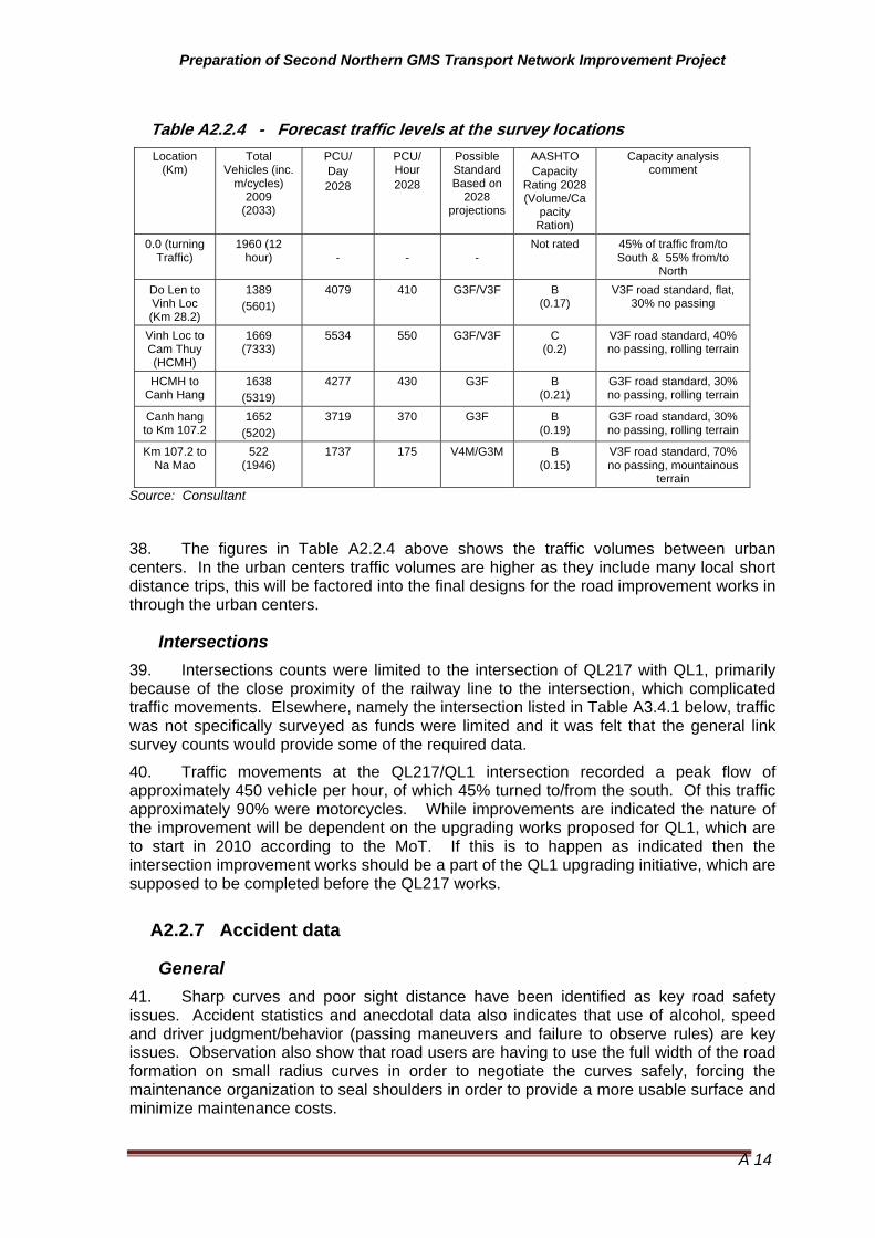
38. The figures in Table A2.2.4 above shows the traffic volumes between urban centers. In the urban centers traffic volumes are higher as they include many local short distance trips, this will be factored into the final designs for the road improvement works in through the urban centers.
Intersections 39. Intersections counts were limited to the intersection of QL217 with QL1, primarily because of the close proximity of the railway line to the intersection, which complicated traffic movements. Elsewhere, namely the intersection listed in Table A3.4.1 below, traffic was not specifically surveyed as funds were limited and it was felt that the general link survey counts would provide some of the required data.
40. Traffic movements at the QL217/QL1 intersection recorded a peak flow of approximately 450 vehicle per hour, of which 45% turned to/from the south. Of this traffic approximately 90% were motorcycles. While improvements are indicated the nature of the improvement will be dependent on the upgrading works proposed for QL1, which are to start in 2010 according to the MoT. If this is to happen as indicated then the intersection improvement works should be a part of the QL1 upgrading initiative, which are supposed to be completed before the QL217 works.
A2.2.7 Accident data
General 41. Sharp curves and poor sight distance have been identified as key road safety issues. Accident statistics and anecdotal data also indicates that use of alcohol, speed and driver judgment/behavior (passing maneuvers and failure to observe rules) are key issues. Observation also show that road users are having to use the full width of the road formation on small radius curves in order to negotiate the curves safely, forcing the maintenance organization to seal shoulders in order to provide a more usable surface and minimize maintenance costs.

Preparation of Second Northern GMS Transport Network Improvement Project
A 15
42. Given the above, the project will need to consider the following works to be part of the future road design :
• Increased curve radius and/or improve sight distance at sharp curves especially those with a poor road safety record;
• Wider traffic lanes around all curves but especially the small radius curves;
• Partially seal shoulders;
• Providing wider and sealed shoulders or footpaths in urban areas;
• Building markets in a number of villages to encourage sellers away from the road surface;
• Building speed humps, roundabouts, or chicanes to reduce traffic speeds at villages;
• Providing centre and edge lines;
• Providing signs to indicate dangerous locations and indicate safe operating speeds; and
• Building escape ramps in areas with long steep grades.
National situation 43. Vietnam established a National Traffic Safety Committee (NTSC) in 1997 and has passed a series of decrees in subsequent years, designed to reduce the rate of traffic accidents and their severity. Traffic Safety Committees have also progressively been established in most provinces and cities where they are headed by the chairman of the province or city.
44. While the committees coordinate the activities of all concerned stakeholders traffic accident prevention initiatives are handled by the Ministry of Public Security Traffic Police Department (TPD) and the Ministry of Transport (VRA and Provincial Departments of Transport) with the TPD being the main repository for traffic accident data. Specific road and provincial traffic data is also available form the provincial transport authorities.
45. Refer to Table A2.2.6 for changes in traffic accident situation in Vietnam.
Thanh Hoa Provincial statistics 46. The Official provincial data accident data for the project road are as follows:
2008 - 171 accidents resulting in 188 deaths and 87 injuries;
147 deaths and 72 injuries were deemed to be caused by excessive speed, alcohol or while overtaking;
177 deaths and 88 injuries involved the occupants of motorized vehicles including cars, vans, trucks, buses, etc; and
The ratio of deaths/injuries between 2 wheel vehicles and 4 or more wheel vehicles was also most 1.7 to 1.
2007 - 193 accidents resulting in 220 deaths and 97 injuries.
177 deaths and 73 injuries were deemed to be caused by excessive speed, alcohol or while overtaking;
196 deaths and 90 injuries involved the occupants of motorized vehicles including cars, vans, trucks, buses, etc:

Preparation of Second Northern GMS Transport Network Improvement Project
A 16
47. The ratio of deaths/injuries between 2 wheel vehicles and 4 or more wheel vehicles was almost 2 to 1. Road users in 4 or more wheeled vehicles are therefore over represented in the statistics.
2006 - 209 accidents resulting in 236 deaths and 90 injuries.1
2005 - 192 accidents resulting in 205 deaths and 74 injuries.2
48. Data available form the Transport Police Bureau showed, for 2008 showed that the months of June to November recorded the lowest rate of accident.
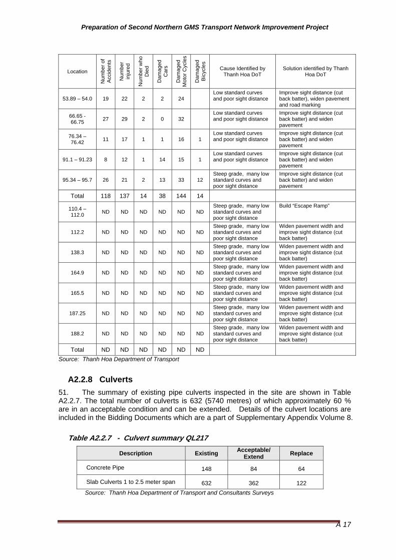
QL217 Accident data 49. Black spot locations are presented in Table A2.2.6 below. This data was collected and collated by the 2 maintenance companies responsible for the maintenance of QL217. The first of these companies summarized the accident history in some detail while the second simply identified road sections that were dangerous.
Comparison with national statistics 50. Available date from published sources, namely the Road Safety in Vietnam Country Report prepared by the ADB - ASEAN Regional Road Safety Program showed that the rates of accident in Lao PDR is decreasing as shown in Table A2.2.5.
Table A2.2.5 - Accident statistical data comparison Viet Nam
Item National Statistics Project Area Project Roads
Fatalities per 10000 vehicles
1995 13.8 2000 10.7 2005 9.4 2009 TBA
Not readily available Not Available
Main causes of accidents 2003 Speeding, overtaking and alcohol
2008 Speed, Alcohol, overtaking TBA
Source: Road Safety in Vietnam Country Report prepared by the ADB - ASEAN Regional Road Safety Program and Thanh Hoa Department of Transport
Table A2.2.6 - Black spot locations on QL 217 (period is not known)
Location
Num
ber o
f A
ccid
ents
Num
ber
inju
red
Num
ber w
ho
Die
d
Dam
aged
C
ars
Dam
aged
M
otor
Cyc
les
Dam
aged
B
icyc
les
Cause Identified by Thanh Hoa DoT
Solution identified by Thanh Hoa DoT
16.7 – 17.3 4 4 0 2 6 Many low standard curves and poor sight distance
Improve sight distance (cut back batter), widen pavement and road marking
25.6 – 26.0 3 2 2 2 2 Low standard curves and poor sight distance
Improve sight distance (cut back batter), widen pavement and road marking
46.18 - 46.38 13 17 2 2 11
Low standard curves and poor sight distance
Improve sight distance (cut back batter), widen pavement and road marking
49.2 – 49.3 7 13 2 2 5 Low standard curves and poor sight distance
Improve sight distance (cut back batter) and widen pavement
1 The 2006 accident statistics were a 2% improvement over the 2005 figures in the case of accident numbers and deaths. Injuries however increased. 2 Transport Police Bureau
Preparation of Second Northern GMS Transport Network Improvement Project
A 17
Location
Num
ber o
f A
ccid
ents
Num
ber
inju
red
Num
ber w
ho
Die
d
Dam
aged
C
ars
Dam
aged
M
otor
Cyc
les
Dam
aged
B
icyc
les
Cause Identified by Thanh Hoa DoT
Solution identified by Thanh Hoa DoT
53.89 – 54.0 19 22 2 2 24 Low standard curves and poor sight distance
Improve sight distance (cut back batter), widen pavement and road marking
66.65 - 66.75 27 29 2 0 32
Low standard curves and poor sight distance
Improve sight distance (cut back batter) and widen pavement
76.34 – 76.42 11 17 1 1 16 1
Low standard curves and poor sight distance
Improve sight distance (cut back batter) and widen pavement
91.1 – 91.23 8 12 1 14 15 1 Low standard curves and poor sight distance
Improve sight distance (cut back batter) and widen pavement
95.34 – 95.7 26 21 2 13 33 12 Steep grade, many low standard curves and poor sight distance
Improve sight distance (cut back batter) and widen pavement
Total 118 137 14 38 144 14
110.4 – 112.0 ND ND ND ND ND ND
Steep grade, many low standard curves and poor sight distance
Build “Escape Ramp”
112.2 ND ND ND ND ND NDSteep grade, many low standard curves and poor sight distance
Widen pavement width and improve sight distance (cut back batter)
138.3 ND ND ND ND ND NDSteep grade, many low standard curves and poor sight distance
Widen pavement width and improve sight distance (cut back batter)
164.9 ND ND ND ND ND NDSteep grade, many low standard curves and poor sight distance
Widen pavement width and improve sight distance (cut back batter)
165.5 ND ND ND ND ND NDSteep grade, many low standard curves and poor sight distance
Widen pavement width and improve sight distance (cut back batter)
187.25 ND ND ND ND ND NDSteep grade, many low standard curves and poor sight distance
Widen pavement width and improve sight distance (cut back batter)
188.2 ND ND ND ND ND NDSteep grade, many low standard curves and poor sight distance
Widen pavement width and improve sight distance (cut back batter)
Total ND ND ND ND ND ND
Source: Thanh Hoa Department of Transport
A2.2.8 Culverts 51. The summary of existing pipe culverts inspected in the site are shown in Table A2.2.7. The total number of culverts is 632 (5740 metres) of which approximately 60 % are in an acceptable condition and can be extended. Details of the culvert locations are included in the Bidding Documents which are a part of Supplementary Appendix Volume 8.
Table A2.2.7 - Culvert summary QL217
Description Existing Acceptable/ Extend Replace
Concrete Pipe 148 84 64
Slab Culverts 1 to 2.5 meter span 632 362 122 Source: Thanh Hoa Department of Transport and Consultants Surveys

Preparation of Second Northern GMS Transport Network Improvement Project
A 18
A2.2.9 Axle load data
General 52. Attempts to carry out a axle load surveys during the course of the project were not successful as the portable axle load equipment that was organized was found to be faulty a few days before the work was to start. As no obvious replacements could be found within an acceptable time frame it was decided to abandon the idea of carrying out axle load surveys. Existing data was located and was used in the determination of traffic oad for pavement design purposes.
Legal loads 53. The relevant standard is the Vietnamese Standard 22TCN307-2006 "Vehicle - General Specification for Safety". Clause 4.1.1.2. Maximum weigh for Axle Load states specified the following limits:
• Single Axle: 10 Tons;
• Tandem Axle,
o if axle space (d) < 1.0 m : 11 tons
o 1.0 m =< d < 3.0 m : 16 tons
o d >= 3.0 m : 18 tons
• Triple Axle
o if axle space (nearest axle, d) =< 1.3 m : 21 tons
o d > 1.3 m: 24 tons.
54. As will be noted there is no differentiation between a 2 wheel single axle and a 4 wheel singe axle, which is surprising as the there is a significant difference in the damage that is cause by each. For example, for a 2 axle truck loaded to 10 tons the damaging factor is 9 while a 10 ton 4 wheel single axle has a damaging factor of 2.2. The damage caused by a 2 wheel axle is therefore approximately 4 times higher. There should therefore be a separate 2 wheel axle load limit. Internationally the legal front axle load limit is typically 5.5 to 6 tons.
55. Table A 2.2.8 below summarizes the damaging factors for a legally loaded trucks and a corrected value that reflects the fact that approximately 40% are empty.
Table A2.2.8 - Damaging Factors (DF) - ESAL by Vehicle Type Vehicle Type Legal Load DF
(assumes 7 ton front axle)
Empty Truck DF
Possible Design DF
(assuming 7 ton front axle)*
Possible Design DF
(assuming 10 ton front axle)*
6 wheel Truck/Bus 3.8 0.15 2.3 5.4
10 wheel Truck 4.4 0.15 2.7 5.7
12 Wheel Truck 6.8 0.15 4.1 7.2
Source: Consultant based on MoT Data Notes: * Assumes 40% of trucks are unloaded.

Preparation of Second Northern GMS Transport Network Improvement Project
A 19
Available Axle Load Data 56. Review of past studies in Vietnam and adjoining countries identified the data summarized in Table A2.2.9 below. Anecdotal data in the form of observations made by the Traffic police from the Thanh Hoa DoT reinforced some of the observation made and reported in axle load surveys conducted as part of the Road Network Improvement Project (RNIP) in 2006, namely that 4 axle trucks, as used to carry the iron ore from Lao PDR that the trucks, were as heavy as 70 tonnes (on 4 axles - 2 x 2 wheel axles and 2 x 4 wheel axles). Trucks carrying cement, timber and other similar materials also heavily loaded (between 45 and 50 tonnes on 4 axle trucks).
57. A summary of the damage factors adopted for the commercial traffic is presented in Table A2.2.9 below. The calculations reflect the fact that most trucks are only loaded for approximately 60% of the time. When empty even heavy trucks cause less than 10% of the damage when they are loaded.
Table A2.2.9 - Damaging Factors (ESAL by Vehicle Type) Vehicle Type Lao Data Vietnam
(RNIP 2006) on Major National Highways
Adopted for Use in Design of QL217
Small Bus _ _ 0.4
Bus 1.5 1.5 1.5
Small truck 0.2 _ 0.2
6 wheel Truck 0.8 1.5 2.3
10 wheel Truck ** 0.8 to 10 4 4.4
12 Wheel Truck ** 1.8 to 28 7 - 12 8.9
12 Wheel Cement and Material Trucks
24 26 24
12 Wheel Iron Ore Truck (or similar)
89.0 ND 89
Source: RNIP, MoT ,Project and Axle load surveys
Notes: ** Range reflects the fact that trucks loads vary form legal loads through to extreme overloading (40 to 79 tons on 3 and 4 axle trucks).
A2.2.10 Rural Roads 58. The project screened more than 500 km of roads identified a long list of 170 km (Annex E of Part A) which was finally reduced to 115 km. The selected roads are detailed below. The screening process is described in Annex E of Part A.

Preparation of Second Northern GMS Transport Network Improvement Project
A 20
A3.0 Road alignment
A3.1 General 59. The proposed standards are shown in Table A3.1.1 below. The Vietnamese road standards are summarized Annex A of Part A.
Table A3.1.1 Adopted Road Standards
Location (Km)
Start Location End Location Present Standard (S)
Proposed Standard (PS)
0 to 28.2 QL1 intersection Intersection with QL45 Class 4 mountain VN3 Flat
28.2 to 31.4 Vin Loc Bypass
QL45/QL217 - common section
QL45/QL217 - common section Class 3 Plus VN3 Flat
31.4 to 54.3 QL45/QL217 - common section
Intersection with Cam Thuy Bypass East Class 4 mountain VN3 Flat
54.3 to HCMHY Cam Thuy Bypass East
Intersection with Cam Thuy Bypass East
Section of Ho Chi Minh Highway
Class 4 mountain (Existing Road)
VN3 Flat
Coincident road-section with HCMH
Section of Ho Chi Minh Highway
Section of Ho Chi Minh Highway Class2
NO CHANGE (Not in Project)
HCMH to 60 Section of Ho Chi Minh Highway Km 60 Class 4 mountain VN3 Mountain
(Rural)
60 to 96 Km 60 Km 96 Class 4 mountain VN3 Mountain (Rural)
96 to 104.7 Km 96 Km 104.7 Intersection with QL15 eastern end Class 5 VN3 Mountain
(Rural)
104.7 to 107.2 Coincident road-section with QL 15
Km 104.7 Intersection with QL15 eastern end
Km 107.2 Intersection with QL15 western end Class 5 mountain
NO CHANGE (Not in Project)
107.2 to 195.4 Intersection with QL15A western end
Start of Border Facility Pavement (point where
it starts to widen) Class 5 mountain VN4 Mountain
195.4 to 195.8 Start of Border Facility Pavement (point where
it starts to widen) Border Variable
NO CHANGE (Not in Project)
Source: Consultant. Based on data provided by Thanh Hoa Department of Transport. PS = Project Proposed Road Standard
60. The QL217 coincides with a section of QL15A (Km 104.7 to Km107) and a section of Ho Chi Minh Highway (Cam Thuy, Km 56.4 to 57.4) and QL45 (Vinh Loc, Km 28.1 to 29.5). These sections are built base on their standards.
61. The adoption of bypass routes, as discussed below, may not effect the works that would be required on the existing QL217 road section.

Preparation of Second Northern GMS Transport Network Improvement Project
A 21
A3.2 Road alignment geometry
A3.2.1 Horizontal alignment considerations
General 62. Road QL217 passes through a mixture of flat and hilly terrain with most of the latter starting west of Km 107.
63. The existing horizontal alignment of the project road in hilly to mountainous terrain is generally of a moderate standard for hilly terrain with average speeds of 45 to 60 kph, and maximum speeds approaching 80 kph on some straight sections. As indicated above the alignment improvements possible in the more difficult terrain, except for the bypasses discussed below, are limited to small improvements in curve radius (horizontal and vertical), curve widening, passing lanes were grades are long and escape lanes where grades are steep and long.
64. It was noted during the inspections that while light vehicles and unloaded vans were often travelling at average speeds of 35 to 40 kph and higher in some of the difficult sections, trucks were typically travelling at speeds of less than 20 kph and as low as 10 kph in the hilly and mountainous terrain. This applied whether the trucks travelled up or down the grade.
Road alignment Improvements 65. It is expected that in addition to the horizontal alignment improvements listed in the Bidding Documents included in Supplementary Appendix Volume 10, it will be necessary to smooth out smaller horizontal. As these changes are small and cannot be specifically identified. The potential cost of the earthworks cost required for the smoothing has however been factored into the cost estimates (multiplier).
66. Of the curves listed in Table A2.2.1 the curve radius were improved on 186 curves. Improvements on the small radius curves were limited to pavement widened in accordance with Table A3.3.1 below. The criteria used to identify the potential for improvement consisted of the following:
• Distance between tangent points of adjacent curves (there is a minimum distance required to allow the superelevation to develop from one direction to another between curves);
• Vertical grade (steep grades had a bigger impact on speed than curve radius); and
• Will improvement in curve radius require the construction of a fill (curves that cross drainage lines were observed to have very steep natural surface grades making it difficult to construct large fills and requiring extensive retaining walls). This questions was assessed, initially from condition data and also from field observations.
A3.2.2 Vertical alignment considerations
General 67. Topography, design speeds, grades, irrigation system requirements, areas of flooding and saturated areas need to be considered as should stopping sight distances. The existing vertical alignment is difficult wherever hilly or mountainous terrain is encountered especially east of Km 107.2, is summarized in Table A2.2.1.

Preparation of Second Northern GMS Transport Network Improvement Project
A 22
68. It will be necessary and possible to improve some vertical curves to improve sight distance and to smooth vertical alignment and road shape deficiencies, As these changes are small and cannot be specifically identified the locations are not identified. The costs of this work are however factored into the cost estimate. Specific issues are discussed below.
Raising of Embankment at Flood Prone and Wet Areas 69. Some parts of project road are flooded during rainy season and are subject to saturation during the rice growing areas (areas where rice fields are higher than the road). The identified road sections are summarized in A2.2.2 above.
Proposed Road Safety Road Features 70. Road safety should be considered in a comprehensive way through all aspects in the design of highways. The safety features that were used in the project road are as follows:
• Provision of a wider (1.5 to 2 metres depending on proposed road standard) sealed shoulder in areas of intensive usage by pedestrians and the slower no-motorized vehicles;
• Provision of improved sight distances;
• Improved horizontal geometry by providing curve widening at on all curves;
• Escape ramps on long and steep grades, if a suitable site can be identified;
• Climbing/passing lanes, where these can be provided;
• Road signs such as warning, information and direction signs, especially at curves less than 50 kph;
• Raised pavement reflectors on small radius curves;
• Lane Markings consist of centerline, edge line and pedestrian crossing;
• Speed humps and/or rumble strip at the entrance of populated town area and through the towns;
• Chicanes, physical traffic islands constructed on the shoulders to reduce speeds to the desired level, where the road passes through communities;
• Traffic islands at key intersection; and
• Guardrails provided on bridge approaches, box culverts and area where sharp curves, moderate to steep grades and high embankments are coincident.
Road Sign and Marking 71. Road signs used in the project roads are classified into three types such as (i) regulatory signs, (ii) warning signs, and (iii) guide signs.
• Regulatory signs give drivers notice of traffic laws and regulations.
• Warning signs direct attention to condition of the road on or adjacent to a street that are potentially hazardous to traffic operation.
• Guide signs indicate route designations, directions/distances, points of interest, and other geographic or cultural information.
• Road markings placed on the pavement, curb, or object to convey traffic regulation and warnings to drivers. The types of road markings used for this
Preparation of Second Northern GMS Transport Network Improvement Project
A 23
project are (i) road centerlines, (ii) pavement edge markings to delineate separation of motor and bike traffic, and (iii) pedestrian crossings.
A3.3 Proposed Road Cross Section Details
A3.3.1 Cross section details
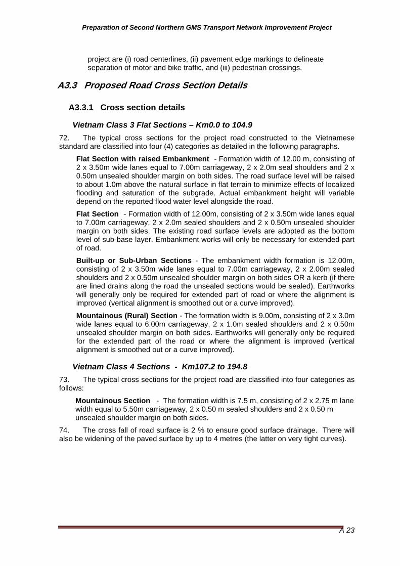
Vietnam Class 3 Flat Sections – Km0.0 to 104.9 72. The typical cross sections for the project road constructed to the Vietnamese standard are classified into four (4) categories as detailed in the following paragraphs.
Flat Section with raised Embankment - Formation width of 12.00 m, consisting of 2 x 3.50m wide lanes equal to 7.00m carriageway, 2 x 2.0m seal shoulders and 2 x 0.50m unsealed shoulder margin on both sides. The road surface level will be raised to about 1.0m above the natural surface in flat terrain to minimize effects of localized flooding and saturation of the subgrade. Actual embankment height will variable depend on the reported flood water level alongside the road.
Flat Section - Formation width of 12.00m, consisting of 2 x 3.50m wide lanes equal to 7.00m carriageway, 2 x 2.0m sealed shoulders and 2 x 0.50m unsealed shoulder margin on both sides. The existing road surface levels are adopted as the bottom level of sub-base layer. Embankment works will only be necessary for extended part of road.
Built-up or Sub-Urban Sections - The embankment width formation is 12.00m, consisting of 2 x 3.50m wide lanes equal to 7.00m carriageway, 2 x 2.00m sealed shoulders and 2 x 0.50m unsealed shoulder margin on both sides OR a kerb (if there are lined drains along the road the unsealed sections would be sealed). Earthworks will generally only be required for extended part of road or where the alignment is improved (vertical alignment is smoothed out or a curve improved).
Mountainous (Rural) Section - The formation width is 9.00m, consisting of 2 x 3.0m wide lanes equal to 6.00m carriageway, 2 x 1.0m sealed shoulders and 2 x 0.50m unsealed shoulder margin on both sides. Earthworks will generally only be required for the extended part of the road or where the alignment is improved (vertical alignment is smoothed out or a curve improved).
Vietnam Class 4 Sections - Km107.2 to 194.8 73. The typical cross sections for the project road are classified into four categories as follows:
Mountainous Section - The formation width is 7.5 m, consisting of 2 x 2.75 m lane width equal to 5.50m carriageway, 2 x 0.50 m sealed shoulders and 2 x 0.50 m unsealed shoulder margin on both sides.
74. The cross fall of road surface is 2 % to ensure good surface drainage. There will also be widening of the paved surface by up to 4 metres (the latter on very tight curves).

Preparation of Second Northern GMS Transport Network Improvement Project
A 24
Figure A3.1 - Basic Road Cross Section - Vietnam class 3 (F)
Note: In the Flat the formation width is 12.0 meters consisting of 2 traffic lanes of 3.5 meters and shoulders of 2.5 meter each side
Figure A3.2 - Basic Road Cross Section - Vietnam class 3 (M (R))
Note: In the mountains rural the formation width is 9.0 meters consisting of 2 traffic lanes of 3.0 meters and shoulders of 1.5 meter each side. Figure A3.3 - Basic Road Cross Section - Vietnamese Class 4 (M)
Note: In the mountains the formation width is 7.5 meters consisting of 2 traffic lanes of 2.75 meters and shoulders of 1.0 meter each side
Subbase Base
2.0 m
AC
3.5m
0.5m 0.5m 3.5m 2.0 m
12.0 m
Subbase Base
1.0 m
AC
3.0m 0.5m 0.5m 3.0m 1.0 m
9.0 m
Subbase Base
0.5 m
AC
2.75m 0.5m 0.5m 2.75m 0.5 m
7.5 m
Preparation of Second Northern GMS Transport Network Improvement Project
A 25
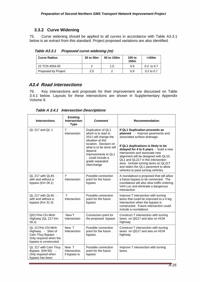
3.3.2 Curve Widening 75. Curve widening should be applied to all curves in accordance with Table A3.3.1 below is an extract from this standard. Project proposed variations are also identified.
Table A3.3.1 Proposed curve widening (m) Curve Radius 30 to 50m 50 to 100m 100 to
150m >150m
22 TCN 4054-05 2 1.5 0.9 0.2 to 0.7 Proposed by Project 2.5 2 0.9 0.2 to 0.7
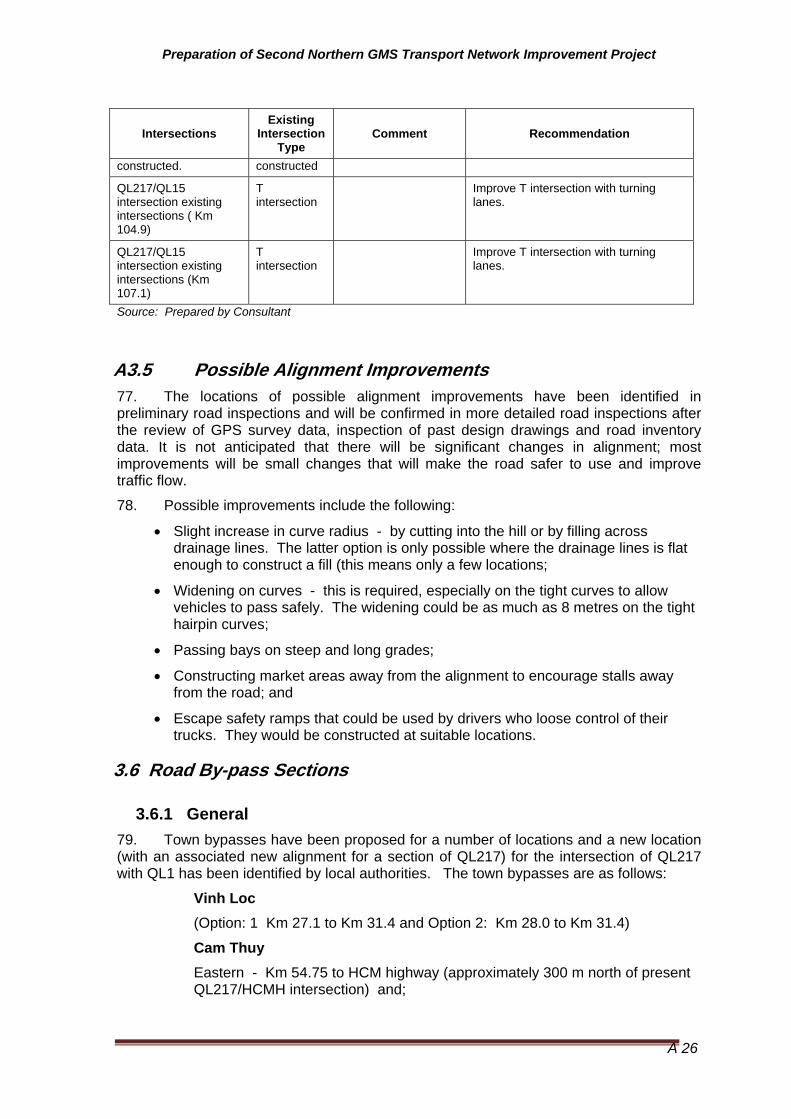
A3.4 Road intersections 76. Key intersections and proposals for their improvement are discussed on Table 3.4.1 below. Layouts for these intersections are shown in Supplementary Appendix Volume 9.
Table A 3.4.1 Intersection Descriptions
Intersections Existing
Intersection Type
Comment Recommendation
QL 217 and QL 1 T Intersection
Duplication of QL1 which is to start in 2011 will change the situation at this location. Decision on what is to be done will depend improvements to QL1 - could include a grade separated interchange
If QL1 Duplication proceeds as planned - Improve pavements and associated surface drainage; If QL1 duplications is likely to be delayed for 4 to 5 years - build a new intersection and associate new alignment will be designed with QL10, QL1 and QL217 in this intersection area. Include turning lanes on QL217 and widen the QL1 pavement to allow vehicles to pass turning vehicles.
QL 217 with QL45 - with and without a bypass (Km 28.1)
Y Intersection
Possible connection point for the future bypass
A roundabout is proposed that will allow a future bypass to be connected. The roundabout will also slow traffic entering Vinh Loc and eliminate a dangerous intersection
QL 217 with QL45 - with and without a bypass (Km 31.4)
T Intersection
Possible connection point for the future bypass
Improve T intersection with turning lanes that could be improved to a 4 leg intersection when the bypass is constructed. Future intersection could include a roundabout.
Ql217/Ho Chi Minh Highway (QL 217 Km 56.2)
New T Intersection
Connection point for the proposed bypass
Construct T intersection with turning lanes on Ql217 and also on HCM highway
QL 217/Ho Chi Minh Highway - Start of Cam Thuy Bypass - Only required when the bypass is constructed.
New T Intersection
Possible connection point for the future bypass
Construct T intersection with turning lanes on Ql217 and also on HCM highway
QL 217 with Cam Thuy Bypass (KM 60) - Only required when bypass has been
New T Intersection if bypass is
Possible connection point for the future bypass
Improve T intersection with turning lanes.
Preparation of Second Northern GMS Transport Network Improvement Project
A 26
Intersections Existing
Intersection Type
Comment Recommendation
constructed. constructed
QL217/QL15 intersection existing intersections ( Km 104.9)
T intersection
Improve T intersection with turning lanes.
QL217/QL15 intersection existing intersections (Km 107.1)
T intersection
Improve T intersection with turning lanes.
Source: Prepared by Consultant
A3.5 Possible Alignment Improvements 77. The locations of possible alignment improvements have been identified in preliminary road inspections and will be confirmed in more detailed road inspections after the review of GPS survey data, inspection of past design drawings and road inventory data. It is not anticipated that there will be significant changes in alignment; most improvements will be small changes that will make the road safer to use and improve traffic flow.
78. Possible improvements include the following:
• Slight increase in curve radius - by cutting into the hill or by filling across drainage lines. The latter option is only possible where the drainage lines is flat enough to construct a fill (this means only a few locations;
• Widening on curves - this is required, especially on the tight curves to allow vehicles to pass safely. The widening could be as much as 8 metres on the tight hairpin curves;
• Passing bays on steep and long grades;
• Constructing market areas away from the alignment to encourage stalls away from the road; and
• Escape safety ramps that could be used by drivers who loose control of their trucks. They would be constructed at suitable locations.
3.6 Road By-pass Sections
3.6.1 General 79. Town bypasses have been proposed for a number of locations and a new location (with an associated new alignment for a section of QL217) for the intersection of QL217 with QL1 has been identified by local authorities. The town bypasses are as follows:
Vinh Loc
(Option: 1 Km 27.1 to Km 31.4 and Option 2: Km 28.0 to Km 31.4)
Cam Thuy Eastern - Km 54.75 to HCM highway (approximately 300 m north of present QL217/HCMH intersection) and;

Preparation of Second Northern GMS Transport Network Improvement Project
A 27
Western - From HCM highway (0.5 to 1.5 km south of present QL217/HCMH intersection) and Km 60 on QL217.
80. While the alternative alignments (bypasses) appear to be possible there is a question over whether significant traffic would transfer to the bypass, to justify their construction. The bypasses were assessed to the extend possible although this was hampered by difficulties with obtaining developments plans in the case of Vinh Loc and the fact that it was not possible to carry out as many traffic studies as would have been desirable.
3.6.2 Intersection of QL217 with QL1 81. The proposed alignment was intended to divert traffic away from the existing settlement that has developed immediately adjacent to the railway crossing and intersection with QL1 and also to move the intersection to a point where it would be possible to improve the intersection. As most of the traffic issues concerned QL1 most of the improvements would be required at on QL1.
82. Points taken into consideration were as follows:
• Intersection issues are more of a concern for QL1 where turning traffic onto and from QL217 restricts “through” traffic movement as there are no turning lanes on QL1 for these turning movements;
• Approximately 400 vehicles (80% motorcycles) make a turn from or onto QL217 in the busiest hour;
• There are 20 trains per day, which stop the traffic entering or leaving QL217 for periods of approximately 5 minutes. This applies specifically to all vehicles except motorcycles which are often inconveniences for approximately 1 minute;
• QL1 is to be duplicated and reconstructed (initial advice was that this would happen in 5 years. Recent advice suggests that the work would start in 2010, before work on QL217 would commence;
• Railway line will be upgraded to an electrified and a second track constructed before 2020;
• Extension of QL217, to connect to QL10 is proposed - date unknown; and
• Work on QL1 is likely to have been started well before that on QL217. Road works on QL217 will therefore need to fit in with plans developed for QL1.
83. Potential solutions include the following:
1) Interchange that takes into account the railway upgrading works, the QL1 upgrading works and also the proposals for extending QL217 beyond its present termination point at QL1;
2) Turning lanes on QL1 to cater for QL217 traffic at the new intersection as identified in Supplementary Appendix Volume 10. This could initially be without traffic lights, but would need traffic lights that were coordinated with train movements. Design for QL217 would also have lanes for turning traffic;
3) Temporary pavement widening works on QL217 at the proposed new intersection. QL217 would include semi permanent road works with turning lanes; and
4) Do nothing other than to repair and resurface the pavement,
Preparation of Second Northern GMS Transport Network Improvement Project
A 28
Proposal - The master plan for improvement in this region included the intersection with QL1, QL10 and QL217 will be implementing. Above result of consultant study will be referred to the master plan. And then traffic surveys and design will be done base on the master plan. Existing alignment of QL217 in this area is proposed till location of intersection is decided.
This proposal is confirmed by PMU1, VRA and MOT in March 2010.
3.6.3 Possible Town Bypasses 84. The potential bypasses identified by the project team and also provincial and district authorities total three (3) the one at Vinh Loc having two alternatives. In all instances the proposed alignments are intended to divert traffic away from town streets by rerouting the QL 217 across agricultural land. The details are discussed below.
85. Figure 2.1 above shows the general alignments superimposed on satellite imagery.
Vinh Loc 86. The proposed options considered below were sited in the 2007 Inception report prepared by TEDI. They considered 2 possible options, one proposed by TEDI and a second proposed by the local authorities. The options as well as the existing alignment are shown in Figure A2.2.1. Both alignment connect to the bypass of Ho’s Palace, at its junction with LQ45. It is also worth nothing that QL217 and QL45 are coincident between km 28.2 and 31. And also that irrespective of which alternative is adopted or if neither is adopted the road section between Km m 29.4 and 31.4 will still need to be improved.
Alternative 1 (Km 27.1 to Km 31.4) 87. The first alternative joins QL217 at Km 27.1 (on the eastern outskirts of Vinh Loc) and in doing so bypasses virtually all of Vinh Loc. Unfortunately survey data indicates that the traffic on QL217 turns onto QL45 at the eastern junction of the 2 roads (Km 28.2). This would indicate that, even if the bypass were constructed a significant proportion (QL217 and QL45 traffic wishing to go south at Vinh Loc. along QL45) would not use the bypass. It is therefore not recommended for further consideration
Alternative 2 (Km 28.2 to Km 31.4) 88. Alternative 2 starts at Km 28.2 adjacent to the present Intersection of QL217 and QL45. Its advantage over Alternative 1 is that will caters for the indicated traffic movements, to the south. Anticipated traffic levels while likely to be significantly higher than on Ql217 will still be low even in 15 to 20 years time.
Proposal - Given the above and the lack of urgency to construct a Bypass (Alternative 2). However consultant compared the bypass (Alternative 2) and existing route. Bypass is economic. Cost including resettlement and land acquisition cost of both scheme existing alignment and bypass is shown in Table A3.6.1 below.
The bypass (Alternative 2) is recommended as part of the project road. An origin destination should be carried out during the design stage to more fully assess the requirement and to locate a definite route.

Preparation of Second Northern GMS Transport Network Improvement Project
A 29
Table A3.3.1 Proposed curve widening (m) Existing alignment Bypass Construction cost 2.69 M USD 2.51 M USD RC and/or LC 0.80 M USD 0.63 M USD Total 3.49 M USD 3.14 M USD
Construction cost: as of 2011, including contingency and Tax RC, LC: Resettlement cost, Land acquisition cost
Cam Thuy (East) 89. The option was proposed by the District of Cam Thuy some years ago. The proposed bypass is located on agricultural land and immediately to the north of the houses which are located along the present Ql217. Advantages of this bypass include the elimination of 2 small radius curves on the eastern limits of the built up areas and the relocation of the intersection with the Ho Chi Minh Highway, away from the River Ma bridge and the market that has developed in this area and along the present QL217. Location is as indicated in Figure A2 2.1 above.
Proposal - Cam Thuy bypass is recommended.
Cam Thuy (West) 90. The option was proposed by the District of Cam Thuy some years ago. The proposed bypass is located largely on agricultural land although it is close to houses at its junction with the HCM highway (300 meters south of the present intersection) and also at Km 59/95 on the present QL217. Traffic levels along the bypass are likely to be relatively low initially, increasing to an approximate maximum of 150 vehicles per hour (vph) in about 2025 (50 vph in 2015). This does not indicate an urgent need for a bypass at this time.
91. The consultant has made a comparison between existing alignment and bypass considered touch point is km 60 on QL217. Bypass scheme is economic. Cost including resettlement and land acquisition cost of both scheme existing alignment and bypass is shown in Table A3.6.2 below.
Table A3.3.1 Proposed curve widening (m) Existing alignment Bypass Construction cost 1.08 M USD 0.63 M USD RC and/or LC 0 M USD 0.31 M USD Total 1.08 M USD 0.94 M USD
Construction cost: as of 2011, including contingency and Tax RC, LC: Resettlement cost, Land acquisition cost
92.
Proposal – Cam Thuy (West) bypass is recommended. A few touch points on present QL217 are proposed. An origin destination should be carried out during the design stage after surveys e.g. topography survey, resettlement survey to more fully assess the requirement and to locate a appropriate route.

Preparation of Second Northern GMS Transport Network Improvement Project
A 30
A4.0 Drainage Structures and Weighbridge
A4.1 General 93. Four options have been envisaged for drainage structures, new construction, extension of existing structure, replacement and use without improvement in consideration of the following criteria.
· New Installation at realignment section and raised embankment sections;
· Extension of existing culverts where the existing condition is good and location and invert elevation are adequate, but narrower than the planned road width;
· Replacement where location, size, and/or discharge are not adequate or existing structure are damaged, have settled or a filled with sediment; and
· Use of Existing Structure where the location, size, width, status, etc of the existing drainage structures are adequate, these structures will be used as they are.
A4.2 Pipe and Box/Slab Culverts 94. The pipe and box culvert requirements, by road section are shown in Tables A4.1 and A4.2 respectively. Detailed list is included in the Bidding Documents included in Supplementary Appendix Volume 10.
Table A4.2.1 Summary of Pipe Culverts Requirements Description Km 0 to 56.4 Km 57.4 to Km 107.2 Km 107.2 to Na Mao Replace 51 765 13 169 0 0
New Construction 7 104 0 0 0 0
Extend Existing 21 256 20 178 43 258
Total (future) 79 1125 33 347 43 258
Table A4.2.2 Summary of Box /Slab Culvert Requirements Description Km 0 to 56.4 Km 57.4 to Km 107.2 Km 107.2 to Na Mao Replace 78 1170 44 572 0 0
New Construction 3 45 0 0 0 0
Extend Existing 31 246 76 596.5 255 1530
Total (future) 112 1461 120 1168.5 255 1530
A4.3 Weighbridge 95. It is proposed that an axle load facility is established at approximately Km 106. A second part time site should be located at approximately Km 31.4 immediately adjacent to the intersection of QL45 and QL217. This second site should be semi permanent facility initially. In both instances the site works would consist of the following:
• Construction of a weighbridge area and building, including a parking area for overloaded trucks;

Preparation of Second Northern GMS Transport Network Improvement Project
A 31
• Construction of approach and departure lanes, back to the highway; and
• Weigh scale equipment (Static/Weigh in Motion) with connections to power and communications at approximately km 107. Concrete pad for part time scales for Km 31.4.

Preparation of Second Northern GMS Transport Network Improvement Project
A 32
A5.0 Pavement Design
A5.1 General 96. While a number of surfacing types are normally considered possible and/or recommended for the Class3 road an asphalt concrete (AC) surface is preferred by the MoT. In the case of a Class 4 road a DBST seal is often seen as acceptable. Both an AC and DBST surfacing have been considered in the design discussed below as while a 12 cm AC surfacing layer is preferred it is expensive.
97. Pavement layer thickness has been based on subgrade conditions and traffic levels, using both the AASHTO and Vietnamese design standards. To ensure a longer pavement life it is proposed that the following variations to the standard Vietnamese design be adopted:
• The practice in Viet Nam of placing soil shoulders either side of the pavement is replaced with a full width pavement design as shown in Figure A3.1 above. It is further proposed that a minimum of 1.0 metres of the shoulder is sealed. This would be widened to 2 metres in villages and settlements.;
• The modulus of AC drops significantly when pavement temperatures are high, as they are for much of the year in Viet Nam. The modulus of AC also drops as the duration of load increases (speed of truck reduces). For example, a drop in truck speed from 60 kph to 30 kph will result in approximately a 50% reduction in effective modulus. As truck speeds are an average of around 40 kph in flat terrain (based on observation) and half this speed in the hilly to mountainous terrain the performance of AC layers will be well below their best, and that often assumed;
• Strength of subgrade and pavement layers is impacted significantly by moisture. Soils therefore need to be tested at the moisture contents (weighted average) found in the field and the design method needs to factor in the drainage conditions likely to be found along the road; and
• Material specifications for pavement layers need to reflect the wetter conditions likely to be found along the project roads. Particular attention needs to be paid to the adoption of suitable plasticity levels.
A5.2 Pavement and materials investigation 98. Pavement investigations started in May 2009. The program of survey works included the following:
• Test pits, logging of pavement structure, DCP, insitu density, and insitu moisture content;
• DCP testing at 40 additional locations;
• Deflection testing on representative section of road - a total of 40 km of road was tested; and
• Borrow pit and quarry sampling and testing.

Preparation of Second Northern GMS Transport Network Improvement Project
A 33
A5.3 Pavement design
General 99. The pavement design is completed, based on existing data, observations and surveyed and investigations. The results of the survey and pavement analysis and design are included in Annex C of Part A.
100. Table A5.1 summarizes the road standard and design traffic load (ESAL) for each of the main road sections. This has been based on the traffic and axle load analysis presented in Section 2 above. Table A5.2 shows the thickness of pavement layers.
Key Assumptions 101. Key Assumptions include the following:
a) It has been assumed that traffic will follow the same wheel path 75% of the time and not the 55% normally assumed. The reasons for this include:
· The cross fall of 2% will tend to force traffic to straddle the centerline;
· The presence of pedestrians, bicycles, pedestrians on the shoulders;
· Use of shoulders and a part of the traffic lanes to dry agricultural produce;
· Observation of traffic behavior - trucks presently straddle the centerline; and
· Narrow lane widths west of Km 107.
b) That conventional crushed/screened pavement materials would be used for base and subbase layer construction.
c) Possible of salvaging the existing pavement material was considered but has not assumed todate. There will be significant vertical alignment smoothing which means cutting into the existing pavement in one area and filling over the pavement in other areas It is therefore possible that it my not be economic to salvage the existing pavement to any great extent.
d) Stabilizing the existing subgrade is a possibility (but has not been assumed) that should be considered as it could reduce costs. Use depends on the type of contractors likely to be engaged to do the work and on a more detailed analysis of available materials.
e) Low traffic speeds of around 15 kph was assumed for the mountains and 40kph for the flat terrain. Low speeds have the effect of lowering modulus and layer equivalence of asphalt concrete.
f) Above average temperatures were assumed . This means lower modulus and layer equivalence of asphalt concrete.

Preparation of Second Northern GMS Transport Network Improvement Project
A 34
Table A5.1 - Project Road Standard and Traffic Load - Vietnam
Road Section/Length Proposed Standard
Formation Width/Pavement Width *
Design ESAL (million)
0 to 28.2 VN 3 Flat 12.0m / 11.0m 5.3
Km 28.1 to 56.8 (includes by pass between Km 54.8 and H VN 3 Flat 12.0m / 11.0m 10.4
Km 57.5 to 104.9 VN 3 Mountain (Rural)
9.0m / 8.0m 8.7
107.2 to 195.4 VN 4 Mountain 7.5m / 6.5m 7.7
Source: Consultant. Trucks 50% unloaded Note: * Widths in some towns are wider, up to 14 meters of sealed surface
Table A5.2 - QL 217 Pavement Thickness Designs (Preliminary)
Road Section Comment Surfacing Aggregate Base
Granular Subbase
(Select) Subgrade
QL 217
0 to 28.2 Road reconstruction 12cm AC 200 240 -
Km 29.2 to 56.8 (includes by passes between Km 54.8 and Ho Chi Minh Highway
Road reconstruction - also short section of new construction
12cm AC 200 290 -
Km 57.5 to 104.9 (including bypass)
Road reconstruction - also short section of new construction
7cm AC 200 200 150-
107.2 to 144 Road reconstruction 7cm AC 200 200 -
144 to 195.4 Road reconstruction 7cm AC 200 200 -
Rural Roads -
Rural Roads Reconstruction DBST/ SBST 150 150 150
Source: Provisional design is based on a design CBR of 8%
Note: Alternate designs that incorporated a stabilized subbase layer/improved subgrade has been considered and could prove to be a suitable substitute for the crushed rock subbase that would traditionally be used where suitable naturally occurring subbase quality material has not been identified
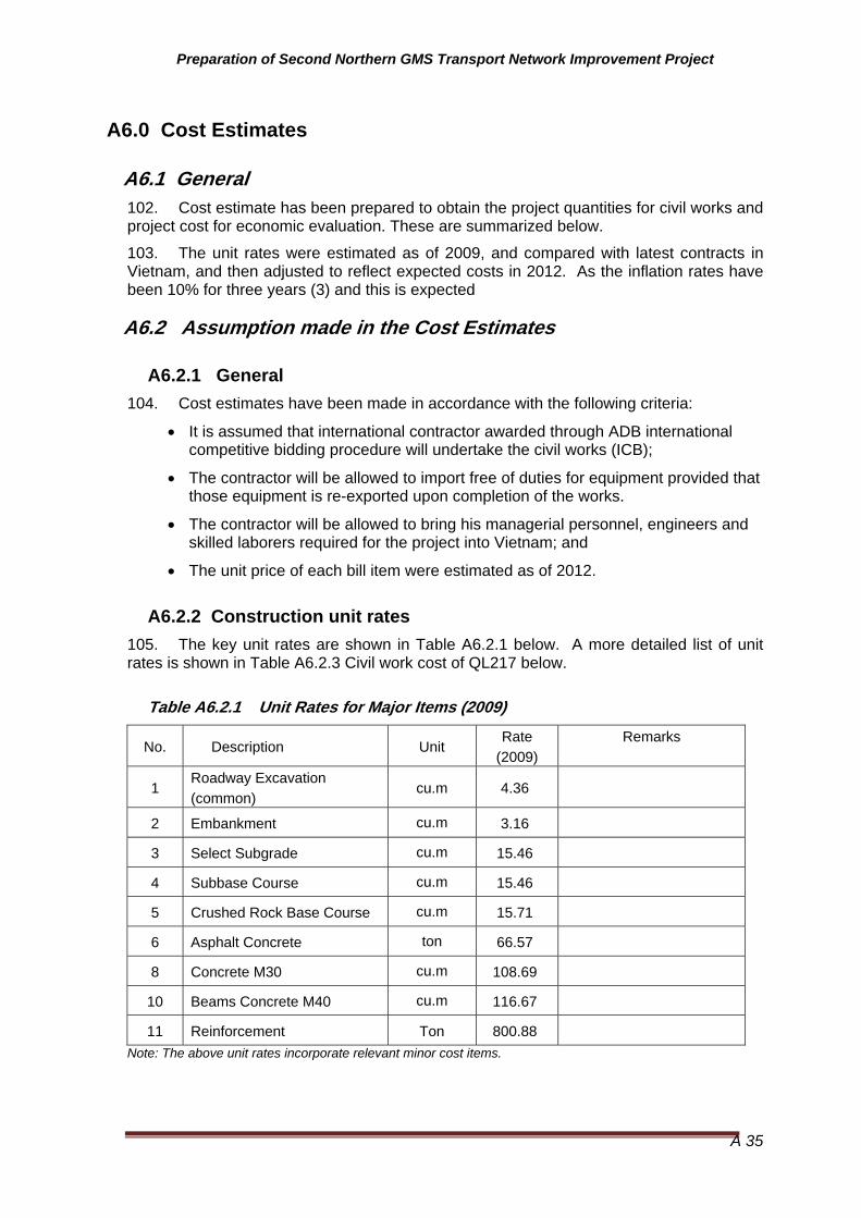
Preparation of Second Northern GMS Transport Network Improvement Project
A 35
A6.0 Cost Estimates
A6.1 General 102. Cost estimate has been prepared to obtain the project quantities for civil works and project cost for economic evaluation. These are summarized below.
103. The unit rates were estimated as of 2009, and compared with latest contracts in Vietnam, and then adjusted to reflect expected costs in 2012. As the inflation rates have been 10% for three years (3) and this is expected
A6.2 Assumption made in the Cost Estimates
A6.2.1 General 104. Cost estimates have been made in accordance with the following criteria:
• It is assumed that international contractor awarded through ADB international competitive bidding procedure will undertake the civil works (ICB);
• The contractor will be allowed to import free of duties for equipment provided that those equipment is re-exported upon completion of the works.
• The contractor will be allowed to bring his managerial personnel, engineers and skilled laborers required for the project into Vietnam; and
• The unit price of each bill item were estimated as of 2012.
A6.2.2 Construction unit rates 105. The key unit rates are shown in Table A6.2.1 below. A more detailed list of unit rates is shown in Table A6.2.3 Civil work cost of QL217 below.
Table A6.2.1 Unit Rates for Major Items (2009)
No. Description Unit Rate
(2009) Remarks
1 Roadway Excavation (common)
cu.m 4.36
2 Embankment cu.m 3.16
3 Select Subgrade cu.m 15.46
4 Subbase Course cu.m 15.46
5 Crushed Rock Base Course cu.m 15.71
6 Asphalt Concrete ton 66.57
8 Concrete M30 cu.m 108.69
10 Beams Concrete M40 cu.m 116.67
11 Reinforcement Ton 800.88
Note: The above unit rates incorporate relevant minor cost items.
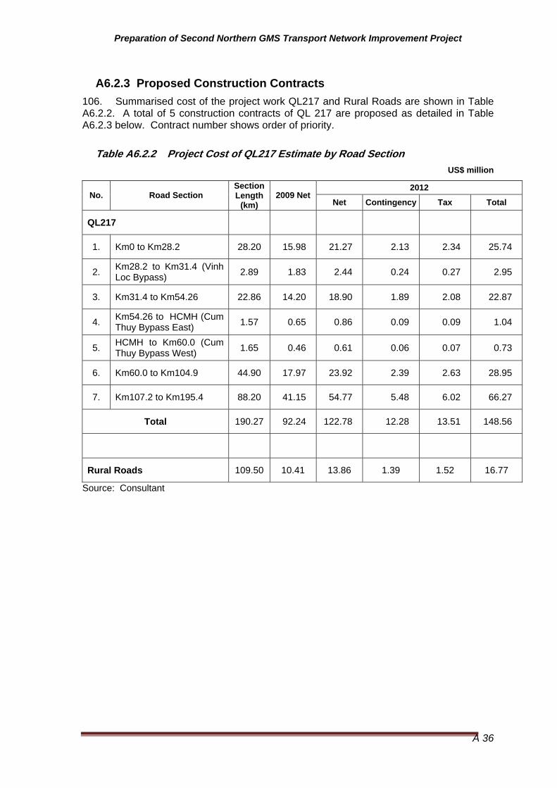
Preparation of Second Northern GMS Transport Network Improvement Project
A 36
A6.2.3 Proposed Construction Contracts 106. Summarised cost of the project work QL217 and Rural Roads are shown in Table A6.2.2. A total of 5 construction contracts of QL 217 are proposed as detailed in Table A6.2.3 below. Contract number shows order of priority.
Table A6.2.2 Project Cost of QL217 Estimate by Road Section US$ million
2012 No. Road Section
Section Length
(km) 2009 Net
Net Contingency Tax Total
QL217
1. Km0 to Km28.2 28.20 15.98 21.27 2.13 2.34 25.74
2. Km28.2 to Km31.4 (Vinh Loc Bypass) 2.89 1.83 2.44 0.24 0.27 2.95
3. Km31.4 to Km54.26 22.86 14.20 18.90 1.89 2.08 22.87
4. Km54.26 to HCMH (Cum Thuy Bypass East) 1.57 0.65 0.86 0.09 0.09 1.04
5. HCMH to Km60.0 (Cum Thuy Bypass West) 1.65 0.46 0.61 0.06 0.07 0.73
6. Km60.0 to Km104.9 44.90 17.97 23.92 2.39 2.63 28.95
7. Km107.2 to Km195.4 88.20 41.15 54.77 5.48 6.02 66.27
Total 190.27 92.24 122.78 12.28 13.51 148.56
Rural Roads 109.50 10.41 13.86 1.39 1.52 16.77
Source: Consultant

Preparation of Second Northern GMS Transport Network Improvement Project
A 37
Table A6.2.3 - Project Road Civil work Costs (2012 prices)
2012 US$ Contract
No. Road Section Length
(Km)
Road Standard/ Surface
2009 Net US$ Net Contingency Tax Total
QL217
1 Km154.0 to Km195.4 4.40 VN 4 M/ AC 70 21,5932,710 28,749,897 2,873,990 3,161,389 34,775,275
2 Km107.20 to Km154.0 46.80 VN 4 M/ AC 70 19,557,353 26,030,837 2,603,084 2,863,392 31,497,313
3 HCMH to Km104.9 inc. Cum Thuy West Bypass 46.55 VN 3 M R/
AC 70 18,430,739 24,531,314 2,453,131 2,698,445 29,682,890
4 Km31.4 to HCMH inc. Cum Thuy East Bypass 24.43 VN 3 Flat/
AC 120 14,848,906 19,763,894 1,976,389 2,174,028 23,914,312
5 Km0.00 to Km31.4 inc. Vin Loc Bps. 31.09 VN 3 Flat/
AC 120 17,813,577 23,709,870 2,370,987 2,608,086 28,688,943
Total 190.27 92,243,285 122,775,813 12,277,581 13,505,339 148,558,733
RR Rural Roads 109.5 Various 10,410,099 13,855,841 1,385,584 1,524,143 16,765,568
Source: Consultant:
Contractor number shows priority order

Preparation of Second Northern GMS Transport Network Improvement Project
A 38
Table A6.2.3 - Civil work Costs of QL217
No. Work Items Ref. No. Unit Quantity Unit Price
USD Total Amont
A GENERAL 100
Mobilization and Demobilization 102.01 ls 1 1,533,424.65 Laboratory and Testing 104.01 ls 1 876,242.66 Control of Traffice 108.01 ls 1 876,242.66
Field Engineering and Working Drawings preparation 109.01 ls 1 306,684.93
Insurerance for works ls 1 525,745.59B ROAD
1 EARTHWORK 200
Clearing and Grubbing 201.01 ha 79 1,388.89 109,276.55 Common Earth Excavation 203.01 m3 4,182,616 4.36 18,230,093.96 Rock Excavation 203.02 m3 494,227 5.56 2,746,171.28 Common Embankment 203.04 m3 716,445 3.61 2,586,995.05
Selected Embankment (Behind Abutment, etc...) 203.05 m3 9,880 13.12 129,606.14
Subgrade Preparation 204.01 m2 1,758,329 0.29 507,928.512 BASE COURSES 300
Subgrade 300.01 m3 78,434 15.46 1,212,829.79 Subbase Course 301.01 m3 404,758 15.46 6,258,786.76 Crushed Aggregate Base Course 302.01 m3 331,352 15.71 5,205,351.683 PAVEMENT WORK 400
Asphalt Concrete Binder Course 401.01 t 331,242 66.57 22,049,950.37 Asphalt Concrete Surface Course 401.01 t 3,509 66.57 233,613.49 Prime Coat 402.01 m2 1,580,705 0.82 1,302,705.43 Tack Coat 402.02 m2 602,883 0.49 297,087.85C Structure
1 CULVERT
Reinfoced Concrete Pipe Culvert D1000 609.04 m 1,215 138.91 168,778.67
Reinfoced Concrete Pipe Culvert D1500 609.11 m 541 311.17 168,238.77
Reinfoced Concrete Box Culvert 1000x1000 609.06 m 2,772 314.70 872,186.58
Reinfoced Concrete Box Culvert 1500x1500 609.13 m 14 396.79 5,555.04
Reinfoced Concrete Box Culvert 2000x2000 609.09 m 95 530.25 50,108.28
Reinfoced Concrete Box Culvert 2500x2500 609.14 m 15 759.85 11,017.78
Reinfoced Concrete Box Culvert 3000x3000 609.15 m 17 956.63 15,784.35
Reinfoced Concrete Box Culvert 4000x4000 609.16 m 71 1,494.44 105,806.60
2 BRIDGE
A. Construction work
2.1 Detour Works
Product temporary steel beam 602 T 381 694.12 264,676.56 Intallation steel beam T 381 245.00 93,419.83 Remove steel beam 202 T 381 146.99 56,049.95
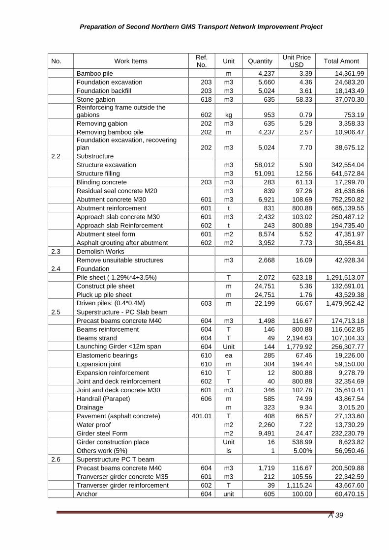
Preparation of Second Northern GMS Transport Network Improvement Project
A 39
No. Work Items Ref. No. Unit Quantity Unit Price
USD Total Amont
Bamboo pile m 4,237 3.39 14,361.99 Foundation excavation 203 m3 5,660 4.36 24,683.20 Foundation backfill 203 m3 5,024 3.61 18,143.49 Stone gabion 618 m3 635 58.33 37,070.30
Reinforceing frame outside the gabions 602 kg 953 0.79 753.19
Removing gabion 202 m3 635 5.28 3,358.33 Removing bamboo pile 202 m 4,237 2.57 10,906.47
Foundation excavation, recovering plan 202 m3 5,024 7.70 38,675.12
2.2 Substructure
Structure excavation m3 58,012 5.90 342,554.04 Structure filling m3 51,091 12.56 641,572.84 Blinding concrete 203 m3 283 61.13 17,299.70 Residual seal concrete M20 m3 839 97.26 81,638.66 Abutment concrete M30 601 m3 6,921 108.69 752,250.82 Abutment reinforcement 601 t 831 800.88 665,139.55 Approach slab concrete M30 601 m3 2,432 103.02 250,487.12 Approach slab Reinforcement 602 t 243 800.88 194,735.40 Abutment steel form 601 m2 8,574 5.52 47,351.97 Asphalt grouting after abutment 602 m2 3,952 7.73 30,554.812.3 Demolish Works
Remove unsuitable structures m3 2,668 16.09 42,928.342.4 Foundation
Pile sheet ( 1.29%*4+3.5%) T 2,072 623.18 1,291,513.07 Construct pile sheet m 24,751 5.36 132,691.01 Pluck up pile sheet m 24,751 1.76 43,529.38 Driven piles: (0.4*0.4M) 603 m 22,199 66.67 1,479,952.422.5 Superstructure - PC Slab beam
Precast beams concrete M40 604 m3 1,498 116.67 174,713.18 Beams reinforcement 604 T 146 800.88 116,662.85 Beams strand 604 T 49 2,194.63 107,104.33 Launching Girder <12m span 604 Unit 144 1,779.92 256,307.77 Elastomeric bearings 610 ea 285 67.46 19,226.00 Expansion joint 610 m 304 194.44 59,150.00 Expansion reinforcement 610 T 12 800.88 9,278.79 Joint and deck reinforcement 602 T 40 800.88 32,354.69 Joint and deck concrete M30 601 m3 346 102.78 35,610.41 Handrail (Parapet) 606 m 585 74.99 43,867.54 Drainage m 323 9.34 3,015.20 Pavement (asphalt concrete) 401.01 T 408 66.57 27,133.60 Water proof m2 2,260 7.22 13,730.29 Girder steel Form m2 9,491 24.47 232,230.79 Girder construction place Unit 16 538.99 8,623.82 Others work (5%) ls 1 5.00% 56,950.462.6 Superstructure PC T beam
Precast beams concrete M40 604 m3 1,719 116.67 200,509.88 Tranverser girder concrete M35 601 m3 212 105.56 22,342.59 Tranverser girder reinforcement 602 T 39 1,115.24 43,667.60 Anchor 604 unit 605 100.00 60,470.15

Preparation of Second Northern GMS Transport Network Improvement Project
A 40
No. Work Items Ref. No. Unit Quantity Unit Price
USD Total Amont
Beams reinforcement 604 T 408 800.88 326,749.87 Beams strand 604 T 112 2,194.63 246,776.21 Duck D65/72 604 m 11,145 2.09 23,293.51 duck grouting 604 m3 37 670.11 25,082.81 Launching Girder <21m span 601 Unit 38 2,333.33 88,666.67 Launching Girder >21m span 604 Unit 37 4,833.33 178,833.33 Elastomeric bearings 610 ea 141 67.46 9,511.81 Expansion joint 610 m 288 429.77 123,579.61 Expansion reinforcement 610 T 11 800.88 8,770.86 Joint and deck reinforcement 602 T 137 800.88 109,438.77 Joint and deck concrete M30 601 m3 1,139 102.78 117,037.32 Handrail (parapet) 606 m 771 74.99 57,838.22 Drainage m 305 9.34 2,850.15 Pavement (asphalt concrete) 401.01 T 616 66.57 40,982.91 Water proof m2 3,543 3.02 10,715.54 Girder steel Form m2 3,707 24.47 90,712.86 Girder construction place Unit 15 1,450.55 21,758.28 Others work (5%) ls 1 5.00% 90,479.45
2.7 Superstructure ( Rc Slab beam and Box culvert)
Slab concrete M40 601 m3 747 116.67 87,109.73 Beams reinforcement 602 T 90 800.88 71,757.28 Handrail (parapet) 606 m3 492 77.98 38,354.80 Pavement (asphalt concrete) 401.01 T 202 66.57 13,476.78 Water proof m2 1,056 7.22 7,625.77 Girder steel Form m2 3,862 24.47 94,493.12 Others work (5%) ls 1 5.00% 15,640.87
D ROAD FURNITURE AND PAVEMENT MARKINGS 612
Road Signs 612.01 nos 1,495 148.94 222,655.80 Guide Post 612.02 nos 49,292 15.06 742,514.93 Kilometer Post 612.03 nos 200 370.49 74,098.56 Guardrail 612.04 m 107,701 44.44 4,786,706.93 Pavement Marking 617.01 m2 106,150 11.11 1,179,444.38 Stone Masonry 620.02 m3 10,249 44.44 455,494.92 Gabion 618.03 m3 5,257 15.65 82,264.00 Curb m 37,300 13.83 515,925.23
Lined Side Drainage of Reinforced Concrete m 37,300 100.00 3,730,000.00
Lined Side Drainage of Stone Masonry m 67,700 14.91 1,009,460.49
Irrigation Canal Type 1 (Trapezium) m 700 146.61 102,627.02
F ENVIRONMENTAL 700
Implementing Environmental Management Plan Work Plan 701.08 ls 1 2,555,095 2,555,095.48

Preparation of Second Northern GMS Transport Network Improvement Project
A 41
No. Work Items Ref. No. Unit Quantity Unit Price
USD Total Amont
Weighbridge ls 2 200,000 400,000.00
Sub Total (2009) 92,243,285.17
2009-2010 2010-2011 2011-2012 Sub Total considered annual
escalation(2012) 10% 10% 10% 122,775,812.56
Contingencies 10% 10% 12,277,581.26
Tax 10% 13,505,339.38
Grand Total 148,558,733.20
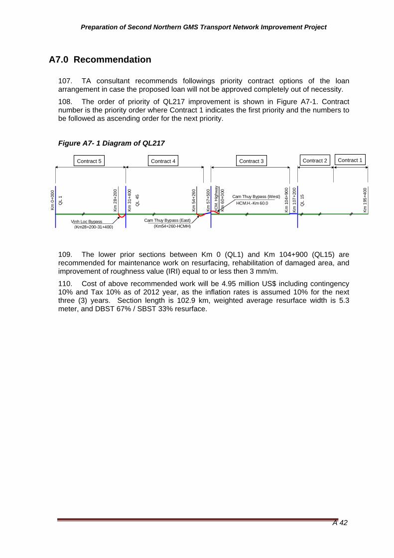
Preparation of Second Northern GMS Transport Network Improvement Project
A 42
A7.0 Recommendation
107. TA consultant recommends followings priority contract options of the loan arrangement in case the proposed loan will not be approved completely out of necessity.
108. The order of priority of QL217 improvement is shown in Figure A7-1. Contract number is the priority order where Contract 1 indicates the first priority and the numbers to be followed as ascending order for the next priority.
Figure A7- 1 Diagram of QL217
109. The lower prior sections between Km 0 (QL1) and Km 104+900 (QL15) are recommended for maintenance work on resurfacing, rehabilitation of damaged area, and improvement of roughness value (IRI) equal to or less then 3 mm/m.
110. Cost of above recommended work will be 4.95 million US$ including contingency 10% and Tax 10% as of 2012 year, as the inflation rates is assumed 10% for the next three (3) years. Section length is 102.9 km, weighted average resurface width is 5.3 meter, and DBST 67% / SBST 33% resurface.
Km 0
+000
QL
1
Km 2
8+20
0
Km 3
1+40
0
QL
45
Km 5
4+26
0
Km 5
7+50
0
HC
M. H
ighw
ayKm
60+
000
Km
104
+900
Km 1
07+2
00
QL
15
Km 1
95+4
00
Cam Thuy Bypass (West)
Vinh Loc Bypass(Km28+200-31+400)
HCM.H.-Km 60.0
Cam Thuy Bypass (East)(Km54+260-HCMH)
Contract 1Contract 2Contract 3Contract 4Contract 5

Preparation of Second Northern GMS Transport Network Improvement Project
A 43
Annex A of Part A Road Standards Vietnam
Table A/A 1 - Road Standards - Classes 3 & 4 (TCVN 4045-05) Item TCVN 4045-05 Class
3 TCVN 4045-05
Class 4 Recommendations
Design Speed kph Flat
RollingMountainous
80 80 60
60 60 40
Pavement Width m (2 lanes)
FlatRolling
Mountainous
7 7 6
7 7
5.5
Rural - Shoulder width (2 sides) m
Flat and Rolling
Mountainous
Urban
5 (4m reinforced) 3 (2m reinforced)
2 (1m reinforced) 2 (1m reinforced)
It is proposed that the shoulders and/or footpath have a width of 2 metres on each side
Type of Pavement Surfacing
AC or DBST DBST Class 3 - DBST or AC Class 4 - DBST
Maximum Grade % Flat
RollingMountainous
5 5 7
6 6 8
Accept existing grades except where there is an opportunity to reduce, if they exceed the GMS standard at any locations.
Minimum Vertical Clearance
4.75 4.5
Structure Loading (minimum)
HL 93 (slightly lower than HS20-44)
HL 93
Width of Formation Flat
RollingMountainous
12 12 9
9 9
7.5
Rural - Corridor of Impact (width that will need to be acquired for construction)*
FlatRolling
MountainousUrban -
Half the width indicated below each side of the design centerline
22 22 19
Approximately12m
Half the width indicated below each side of the design centerline
19 19
17.5 Approximately 12 m
The adoption of higher width standards will have an impact on the number of Affected People and therefore resettlement and compensation costs.
* Corridor of Impact (Rural) = Width of Formation plus width of batters (assume 2 metre each side) plus width for use by equipment (allow 3 metres each side)
Source: Consultant, based on Vietnamese Standard

Preparation of Second Northern GMS Transport Network Improvement Project
A 44
Table A/A 2 - Adopted Geometric Design Standard for QL 217 (Vietnamese Standard TCVN 4054)
Section
Km0 – Km28.2
Vin Loc Bypass
Km31.4 – Km 54.26
Cam Thy East
Bypass
Cam Thy West
Bypass
Km 60 – Km104.9
Km107.2 – Km195.4
No. Main Parameter Unit VN3 Flat VN3 Flat VN3 Flat VN3 Flat VN3 Mo R VN3 Mo R VN4 Mo 1. Design speed km/h 80 80 80 80 60 60 40 2. Number of lanes No. 2 2 2 2 2 2 2 3. Formation width M 12.0 12.0 12.0 12.0 9.0 9.0 7.5 4. Traffic lane width M 3.50 3.50 3.50 3.50 3.00 3.00 2.75 5. Outer shoulder width M 2.00 2.00 2.00 2.00 1.00 1.00 0.50 6. Inner shoulder width M 0.50- 0.50- 0.50- 0.50- 0.50- 0.50- 0.50- 7. Maximum longitudinal gradient % 5 5 5 5 7 7 8 8. Median to be applied over 4-lane M - - - - - - - 9. Minimum horizontal curvature M 250(125) 125 125 125 125(60) 60(30) 60(30)
10. Superelevation at maximum horizontal curvature % 8 8 8 8 7 7 7
11. Minimum radii of vertical curves: crest M 4000 4000 4000 4000 2500 25000 700 12. Minimum radii of vertical curves: sag M 2000 2000 2000 2000 1000 1000 450 13. Cross fall of carriageway % 2 2 2 2 2 2 2 14. Cross fall of shoulder % 4 4 4 4 4 4 4 15. Pavement Structure
Surface Base Course Sub Base Course Subgrade
AC 12 cm
20 cm 24 cm
-
AC 12 cm
20 cm 29 cm
-
AC 12 cm
20 cm 29 cm
-
AC 12 cm
20 cm 29 cm
-
AC 7 cm
20 cm 20 cm 15 cm
AC 7 cm
20 cm 20 cm 15 cm
AC 7 cm
20 cm 20 cm
- M = meter, km/h = kilometer per hour, No. = number. Mo = Mountainous, R = Rural. ( ): absolute minimum considered economic Source: Ministry of Transport.
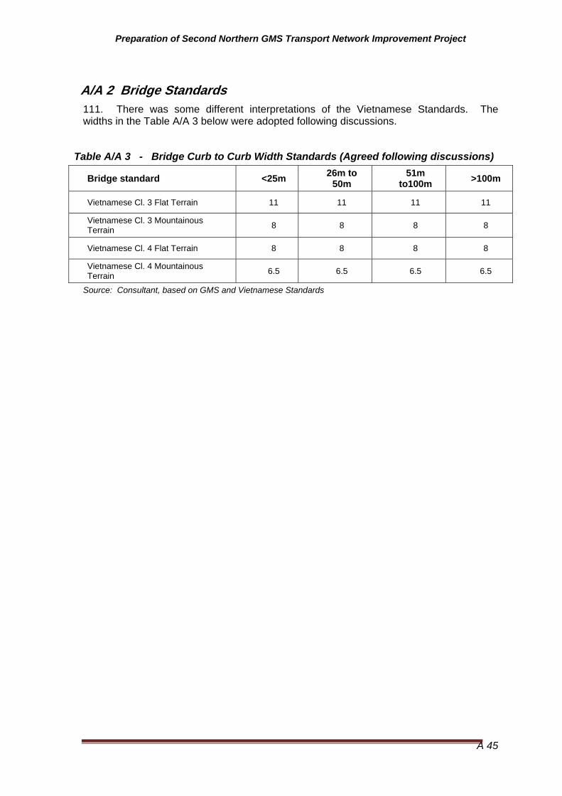
Preparation of Second Northern GMS Transport Network Improvement Project
A 45
A/A 2 Bridge Standards 111. There was some different interpretations of the Vietnamese Standards. The widths in the Table A/A 3 below were adopted following discussions.
Table A/A 3 - Bridge Curb to Curb Width Standards (Agreed following discussions)
Bridge standard <25m 26m to 50m
51m to100m >100m
Vietnamese Cl. 3 Flat Terrain 11 11 11 11
Vietnamese Cl. 3 Mountainous Terrain 8 8 8 8
Vietnamese Cl. 4 Flat Terrain 8 8 8 8
Vietnamese Cl. 4 Mountainous Terrain 6.5 6.5 6.5 6.5
Source: Consultant, based on GMS and Vietnamese Standards

Preparation of Second Northern GMS Transport Network Improvement Project
A 46
Annex B of Part A Road Inventory and Condition
ROAD INVENTORY DATA SHEET
CARRIAGEWAY SHOULDER Details of Formation-Thông tin nền đường 1:2 Side drain
(rãnh dọc)
Culvert
under Road-Cống dưới đườn
g
COMMENT (Ghi chú)
From
Km
To K
m
Terri
ain
(F/ R
/ M)-
Loại
địa
hìn
h(Bằn
g phẳn
g, tr
ung
du, đồi
núi
) La
nd u
se (B
uilt
up/ A
grt./
For
est/
Indu
stria
l/ B
arre
n)-
Sử
dụn
g đấ
t(xây
dự
ng, n
ông
nghiệp
, rừ
ng, c
ông
n ghiệp
, đất
trốn
g)
Vill
age/
Tow
n (N
ame)
(Làn
g, thị t
rấn-
Ghi
rõ tê
n)
Cur
vatu
re (S
harp
, Mod
erat
e,M
ild, S
traig
ht)-Đườn
g co
ng(c
ua gấp
, tru
ng b
ình,
cua
hài
hòa
, đườn
g thẳn
g)
Roa
d G
radi
ent (
Ste
ep, M
oder
ate,
Mild
Fla
t)-Độ
dốc
dọc(
dốc
gắt,
dốc
vừa
phải
, dốc
nhẹ
)
Form
atio
n W
idth
(m)-
Bề
rộng
nền
(m)
Pav
emen
t Typ
e (B
T/ C
C/ G
R/
ER
)-Loạ
i mặt
đườn
g
Pav
emen
t Wid
th (m
)-Bề
rộng
mặt
đườn
g C
rack
ing
(%) 0
=0%
, 1=
<10%
;2=<
30; 3
=<50
%;
4=>5
0%(M
ức độ
nứ
t nẻ
(%)
Rut
ting
(<10
, <20
, >20
mm
)-Mứ
c độ
lún
(0=0
%, 1
<25%
; 2<5
0%;
3=>5
0%)-
Mứ
c độ
hư
hỏn
g/vá
/ổ
Veh
icle
Spe
ed (d
ue to
R
ough
ness
)-Tố
c độ
xe
chạy
(độ
bám
) Ty
pe (B
T/ C
C/ G
R/ E
R)-
Loại
va
i đườn
g
Wid
th (m
)-Bề
rộng
Con
ditio
n (G
/ F/ P
/ VP
)-Tì
nh
trạng
R
oad
Cro
ss s
ectio
n (B
ox C
ut,
Fill,
Sid
e C
ut)-D
ang
mặt
cắt
ng
ang(
chữ
Uđắ
pL)
Em
bank
men
t hei
ght /
Val
ley
side
(m)-C
hiều
cao
đắp
/đào
E
mba
nkm
ent S
lope
/ V
alle
y si
de s
lope
(V:H
)-M
ái dốc
H
ill s
ide
heig
ht (m
)-Chi
eufc
ao
đồi,
núi v
en đườn
g
% o
f hei
ght i
n ro
ck-Tỷ
lệ %
đá
Hill
sid
e N
atur
al S
urfa
ce S
lope
(H
:V)-Độ
dốc
mặt
đất
tự n
hiện
ở
ven đư
ờng
Land
Slid
e (N
/ NU
/ N
S)-
Trượt
lở
đất
Sid
e of
road
(B /
L / R
/ N
)-P
hía
bên
nào
Dra
in ty
pe (V
/ R /
TU /
TL)-
Loại
kế
t cấu
thia
ts nước
Siz
e (c
omm
ent o
n co
nditi
on in
"C
omm
ents
"-K
ích
thước
0.000 0.100 F Built up
Dau Xa Ha Phong
Straight
Mild Flat 8 BT 6 1 <2
0 1 30 GR 1.0 F Fill 0.3 1.5 N B R
0.100 0.200 F Built up Strai
ght Mild Flat 8 BT 6 1 <2
0 1 30 GR 1.0 F Fill 0.3 1.5 N B R
0.200 0.300 F Built up Mod
erate Mild Flat 7 BT 5 1 <2
0 1 30 ER 1.0 F Fill 0.3 1.5 N N
0.300 0.500 F Built up Mod
erate Mild Flat 7 BT 5 1 <2
0 1 30 ER 1.0 F Fill 0.3 1.5 N N Yes(2) Ch.(18.x2),(5.0x5.0)
0.500 0.600 F Built up Mild Mild
Flat 7 BT 5 1 <10 0 30 ER 1.0 F Fill 0.3 1.5 N L R Yes(2
) Ch.(1.2X1.2),(2.5x2.5)

Preparation of Second Northern GMS Transport Network Improvement Project
A 47
ROAD INVENTORY DATA SHEET
CARRIAGEWAY SHOULDER Details of Formation-Thông tin nền đường 1:2 Side drain
(rãnh dọc)
Culvert
under Road-Cống dưới đườn
g
COMMENT (Ghi chú)
From
Km
To K
m
Terri
ain
(F/ R
/ M)-
Loại
địa
hìn
h(Bằn
g phẳn
g, tr
ung
du, đồi
núi
) La
nd u
se (B
uilt
up/ A
grt./
For
est/
Indu
stria
l/ B
arre
n)-
Sử
dụn
g đấ
t(xây
dự
ng, n
ông
nghiệp
, rừ
ng, c
ông
n ghiệp
, đất
trốn
g)
Vill
age/
Tow
n (N
ame)
(Làn
g, thị t
rấn-
Ghi
rõ tê
n)
Cur
vatu
re (S
harp
, Mod
erat
e,M
ild, S
traig
ht)-Đườn
g co
ng(c
ua gấp
, tru
ng b
ình,
cua
hài
hòa
, đườn
g thẳn
g)
Roa
d G
radi
ent (
Ste
ep, M
oder
ate,
Mild
Fla
t)-Độ
dốc
dọc(
dốc
gắt,
dốc
vừa
phải
, dốc
nhẹ
)
Form
atio
n W
idth
(m)-
Bề
rộng
nền
(m)
Pav
emen
t Typ
e (B
T/ C
C/ G
R/
ER
)-Loạ
i mặt
đườn
g
Pav
emen
t Wid
th (m
)-Bề
rộng
mặt
đườn
g C
rack
ing
(%) 0
=0%
, 1=
<10%
;2=<
30; 3
=<50
%;
4=>5
0%(M
ức độ
nứ
t nẻ
(%)
Rut
ting
(<10
, <20
, >20
mm
)-Mứ
c độ
lún
(0=0
%, 1
<25%
; 2<5
0%;
3=>5
0%)-
Mứ
c độ
hư
hỏn
g/vá
/ổ
Veh
icle
Spe
ed (d
ue to
R
ough
ness
)-Tố
c độ
xe
chạy
(độ
bám
) Ty
pe (B
T/ C
C/ G
R/ E
R)-
Loại
va
i đườn
g
Wid
th (m
)-Bề
rộng
Con
ditio
n (G
/ F/ P
/ VP
)-Tì
nh
trạng
R
oad
Cro
ss s
ectio
n (B
ox C
ut,
Fill,
Sid
e C
ut)-D
ang
mặt
cắt
ng
ang(
chữ
Uđắ
pL)
Em
bank
men
t hei
ght /
Val
ley
side
(m)-C
hiều
cao
đắp
/đào
E
mba
nkm
ent S
lope
/ V
alle
y si
de s
lope
(V:H
)-M
ái dốc
H
ill s
ide
heig
ht (m
)-Chi
eufc
ao
đồi,
núi v
en đườn
g
% o
f hei
ght i
n ro
ck-Tỷ
lệ %
đá
Hill
sid
e N
atur
al S
urfa
ce S
lope
(H
:V)-Độ
dốc
mặt
đất
tự n
hiện
ở
ven đư
ờng
Land
Slid
e (N
/ NU
/ N
S)-
Trượt
lở
đất
Sid
e of
road
(B /
L / R
/ N
)-P
hía
bên
nào
Dra
in ty
pe (V
/ R /
TU /
TL)-
Loại
kế
t cấu
thia
ts nước
Siz
e (c
omm
ent o
n co
nditi
on in
"C
omm
ents
"-K
ích
thước
0.600 0.730 F Built up Mild Mild
Flat 7 BT 5 1 <10 0 30 ER 1.0 F Fill 0.3 1.5 N L R
0.730 0.830 F Built up
Het Xa Ha Phong
Mild Mild Flat 7 BT 5 1 <1
0 0 30 ER 1.0 F Fill 0.3 1.5 N L R
0.830 0.970 F Built up Mild Mild
Flat 7 BT 5 1 <10 0 40 ER 1.0 F Fill 0.3 1.5 N L R
0.970 1.000 F Built up Strai
ght Mild Flat 7 BT 5 0 <1
0 0 40 ER 1.0 F Fill 1.8 1.5 N N
1.000 1.100 F Built up Strai
ght Mild Flat 7 BT 5 0 <1
0 0 40 ER 1.0 F Fill 1.8 1.5 N N
1.100 1.200 F Built up Strai
ght Mild Flat 7 BT 5 0 <1
0 0 40 ER 1.0 F Fill 1.8 1.5 N N
1.200 1.300 F Built up Mod
erate Mild Flat 7 BT 5 1 <1
0 0 40 ER 1.0 F Fill 2.5 1.5 N N
1.300 1.400 F Built up Mod
erate Mild Flat 7 BT 5 1 <1
0 0 40 ER 1.0 F Fill 2.5 1.5 N N
1.400 1.500 F Built up Mod
erate Mild Flat 7 BT 5 1 <2
0 0 40 ER 1.0 F Fill 2.7 1.5 N N

Preparation of Second Northern GMS Transport Network Improvement Project
A 48
Annex C of Part A Pavement Analysis - Vietnam
A/C 1.1 GENERAL 112. The pavement investigation was carried out for on the national road QL-217 from Section: QL1 Do Len to Na Mao (Km 0+000 to -194+800). The results of the investigation were used for the preliminary engineering design of the road pavement, which is a part of The Second Northern GMS Transport Network Improvement Project. The pavement investigation was carried out by the Hanoi Design and Consulting Joint Stock Company (HADECON) under the supervision of International Pavement/Material Engineer. The exploration work was performed in May 2009 to June 2009 during the dry season.
A/C 1.2 existing road conditions
113. Pavement condition survey plays an important role in the investigation and determining likely pavement improvement option. Visual observations were carried out along the entire project corridor to examine pavement distress and functional efficiency. The method suggested in HDM manual was used to assess distress areas (cracks, raveling and potholes) and estimated as a percentage of the total carriageway. The overall observed road conditions are summarized below:
114. The project road QL217 extends from QL1 to the Lao PDR border crossing at Na Mao. The road passes through a number of significant towns namely Vinh Loc, Cam Thuy, Canh Nang and Quan Son and also crosses a number of highways, namely QL45, Ho Chi Minh Highway and QL15A. The existing road is typically narrow with a paved surface width of 5 meters for the first 107 kilometers and 3.5 metres further west, through to Na Mao. The exceptions are through some towns where the paved surfaces are as wide as 14 meters. Shoulders are typically less that 1 meter. The road is located in flat and some rolling terrain for the first 107 kilometers after which the road passes through hilly, mountainous and some rolling terrain.
115. Project road pavement conditions are summarized in Table 1.
Table 1: Existing Road Pavement Condition
From (Km) To (Km) Length (km) Pavement
Width (meter) Shoulder
Width (meter) Surface Type Roughness IRI
Crack %
Rut depth (mm)
Patch %
0 0.8 0.8 6 1 Sprayed Seal/macadam 6 20 15 5
0.8 7.7 6.9 5 1 Sprayed Seal/macadam 6 15 20 5
7.7 17.6 9.9 5 1 Sprayed Seal/macadam 6 30 25 5
17.6 28.1 10.5 5 1 Sprayed Seal/macadam 4.8 25 15 3
*28.1 29.5 1.4 NOT IN PROJECT
29.5 31.4 1.9 3.5 1 Sprayed Seal/macadam 7.5 20 10 2
31.4 34.25 2.85 5 1 Sprayed Seal/macadam 6.5 15 15 0

Preparation of Second Northern GMS Transport Network Improvement Project
A 49
From (Km) To (Km) Length (km) Pavement Width (meter)
Shoulder Width (meter) Surface Type Roughness
IRI Crack
%
Rut depth (mm)
Patch %
34.25 38.3 4.05 5 1 Sprayed Seal/macadam 6 15 15 10
38.3 54.8 16.5 5 1 Sprayed Seal/macadam 6 20 20 5
54.8 56.4 1.6 5 1 Sprayed Seal/macadam 6 20 10 3
56.4 57.4 1 NOT IN PROJECT
57.4 58.3 0.9 8 F/path AC 6 10 5 0
58.3 60 1.7 6 1 Sprayed Seal/macadam 7 15 20 5
60 74.2 14.2 5 1 Sprayed Seal/macadam 6 20 25 3
74.2 82 7.8 5 1 Sprayed Seal/macadam 5 20 20 3
82 92.5 10.5 5 1 Sprayed Seal/macadam 5.5 20 20 3
92.5 94.5 2 14 F/path Sprayed Seal/macadam 6.5 10 15 1
94.5 104.2 9.7 5 1 Sprayed Seal/macadam 6 20 15 2
104.2 104.9 0.7 7.5 F/path Sprayed Seal/macadam 6 10 10 1
104.9 107.2 NOT IN PROJECT
107.2 112.3 5.1 6 1 Sprayed Seal/macadam 6 30 20 1
112.3 125.35 13.05 3.5 1.7 Sprayed Seal/macadam 6 20 10 2
125.35 125.9 0.55 5.5 0.6 Concrete 6.5 0 10 5
125.9 141.5 15.6 3.5 1.7 Sprayed Seal/macadam 6 30 25 8
141.5 143.3 1.8 10.5 F/path Sprayed Seal/macadam 5 20 15 2
143.3 145 1.7 3.5 1.7 Sprayed Seal/macadam 5.5 15 10 1
145 157 12 3.5 1.7 Sprayed Seal/macadam 5.5 30 15 2
157 172 15 3.5 1.7 Sprayed Seal/macadam 6 20 15 2
172 195.4 23.4 3.5 1.7 Sprayed Seal/macadam 6.5 30 20 7
A/C1.3 FIELD and LABORATORY INVESTIGATION 116. Field pavement and geotechnical instigation was carried out to support the proper design of the road rehabilitation work. Full details relative to area geology, sampling and testing of the existing roadbed, calculation of CBR values and other geotechnical data which support the conclusions and recommendations included in this section.
117. The following methodology was undertaken to determine in-situ base course and sub-grade strength, pavement condition, laboratory CBR and properties of the existing road materials:

Preparation of Second Northern GMS Transport Network Improvement Project
A 50
• Transport Road Research Laboratory (TRRL) Dynamic Cone Penetrometer was used for the field investigation.
• The test pit locations for DCP was determined by Consultant prior commencement the work at site.
• Test pits were excavated at the edge of the pavement with minimum of 300mm width and 500mm depth.
• Recorded the pavement and soil profile (identifying material type and thickness). • Measured the strength of the subgrade material using the DCP, to a depth of 0.8 meter
from the bottom of the test pit. The number of blows required to drive the probe each 100mm was recorded in the data sheet.
• The number of blows against penetration of the cone was recorded and this data was used to calculate layer depth for average CBR determination, the field CBR is established by the following DCP-CBR relationship equation:
Log10 (CBR) = 2.48-1.057 Log10 (DCP)
• Subgrade soil from the test pit was collected and taken to the laboratory for a number of testing.
118. CBR value for subgrade layer was calculated using equivalent soil layer method:
n21
3/1nn
3/122
3/111
h.............hhCBRh............CBRhCBRhCBR
++++++
=
119. Summary of DCP tests are showed in Annex 1 that represent the sub-grade strength at selected test pit locations.
120. Summary of laboratory tests are showed in Annex 2 that represent the sub-grade material properties at selected test pit locations.
A/C1.4 PAVEMENT MATERIAL OPTIONS and ALTERNATIVES 121. Based on the field and laboratory test results, the existing aggregate layer/layers do not meet the specification of road base/Sub base materials. It is proposed that existing aggregate materials shall be replaced with appropriate crushed/screened materials or can be reused after processing to specified quality of the relevant items. The soil condition along the existing road alignment is proposed to be used for sub-grade material with some minor improvements in few locations.
A/C1.5 PROPOSED PAVEMENT WORKS 122. The existing pavement condition was assessed moderate to severe surface distress or failure and hence, reconstruction was required. While a number of surfacing types were considered for possible and/or recommended for the Class 3 and Class 4 road, an asphalt concrete (AC) surface was preferred by the MoT.
123. Pavement layer thickness has been based on subgrade conditions and traffic levels, using AASHTO Guide for Design of Pavement Structures 1993 and compared with the Vietnam Specification for the Design of Flexible Pavements 22TCN-211-06. To ensure a longer pavement life it is proposed that the following variations to the standard Vietnamese design be adopted:

Preparation of Second Northern GMS Transport Network Improvement Project
A 51
• The practice in Viet Nam of placing soil shoulders either side of the pavement is replaced with a full width pavement design as shown in Figure A3.1 (Engineering Report). It is further proposed that a minimum of 1.0 metres of the shoulder is sealed. This would be widened to 2 metres in villages and settlements.
• The appropriate modulus of AC should be used in relation to the ambient temperature and speed of design vehicle. The modulus of AC drops significantly when pavement temperatures are high, as they are for much of the year in Viet Nam. The modulus of AC also drops as the duration of load increases (speed of truck reduces).
• Strength of subgrade and pavement layers is impacted significantly by moisture. Soils therefore need to be tested at the moisture contents (weighted average) found in the field and the design method needs to factor in the drainage conditions likely to be found along the road; and
• Material specifications for pavement layers need to reflect the wetter conditions likely to be found along the project roads. Particular attention needs to be paid to the adoption of suitable plasticity levels.
A/C1.6 TRAFFIC LOAD 124. In order to properly design a road improvement, it is necessary to know what volumes and types of vehicular traffic will use it. Although there are several classes of possible future traffic to be considered, normal traffic - which is that now using the road under study and will continue to use it after it is improved - is always the most important when rehabilitation of an existing road is being studied. Therefore, its proper quantification is essential, and this involves analysis of current traffic and its historical and future growth.
125. Traffic surveys included classified counts and origin/destination surveys conducted at several locations. Summation of equivalent 18000-lb (80-kN) single axle loads used to convert mixed traffic to design traffic for the design period. Table 2 summarizes the adopted road standards as agreed by PMU1, ADB and the Consultant, and estimated design traffic load (ESAL) for each of the project road sections.
Table 2: Project Road Traffic Load - Vietnam
Road Section/Length Proposed Standard
Pavement/ Formation
Width
Design ESAL
(million)
Km 0 to Km 28.1 VN 3 (F) 11.0/12.0 5.3
Km 28.1 to HCMH VN 3 (F) 11.012.0 10.4
HCMH to Km 104.9 VN 3 (M-R) 8.0/9.0 8.7
Km 107.2 to Km 195.4 VN 4 (M) 5.5/6.5 7.7
Source: Consultant, Trucks 50% unloaded, F: Flat, M: Mountainous, R: Rural A/C1.7 PAVEMENT DESIGN 126. Pavement design was carried out using AASHTO Guide for Design of Pavement Structures 1993 and compared with the Vietnam Specification for the Design of Flexible Pavements 22TCN-211-06. With reasonable maintenance, the pavement as designed will permit the road to support safely the projected number of Equivalent Standard Axle Loads of 18,000 pounds during the 20-year design period.

Preparation of Second Northern GMS Transport Network Improvement Project
A 52
127. Based on the study results, the Consultant proposes that the project road be rehabilitated with an asphalt concrete or double bituminous surface treatment over a crushed-stone base and granular natural subbase, as well as major improvements being made in drainage system. It was found that in-situ moisture content significantly higher than optimum moisture content in significant number of locations.
128. The key parameters for the pavement design were as follow:
1) Design Period: The period of time that a rehabilitated pavement structural section is designed to perform before reaching its terminal serviceability or a condition that requires major rehabilitation or reconstruction; this is also referred to as the performance period. 2) Equivalent Single Axle Loads (ESAL’s): Summation of equivalent 18000-lb (80-kN) single axle loads used to convert mixed traffic to design traffic for the design period. 3) Structural Section: The planned, engineering-designed layers of specified materials (normally consisting of subbase, base, and pavement surface) placed over the basement soil to support the traffic loads anticipated to be accumulated and applied during the design period. The structural section is also commonly called the pavement structural section. 4) Structural Section Drainage System: A drainage system used for both asphalt/bituminous pavements consisting of a treated permeable base layer and a collector system which includes a slotted pipe encapsulated in treated permeable material. Drainage must be kept operating efficiently during the life of the road to prevent the strength/CBR decreasing through weakening of the foundation by a rising water table. 5) Subbase: A layer of aggregate of designed thickness and specified quality placed on the basement soils as the foundation for a base. 6) Subgrade: That portion of the roadbed on which pavement surfacing, base, subbase, or a layer of any other material is placed. 129. The final choice of the recommended rehabilitation alternative is based on choosing a strategy that will provide a total structural section thickness that is adequate to resist the anticipated loading it will experience throughout its design period, the potential for reflective cracking and to improve ride.
130. Based on an analysis of traffic data, observations during a number of field inspection and successive discussions with the client it was decided that all roads would be constructed to a GMS Cl. 3 and VN Cl. 4 standard.
131. Vietnamese specification “Specification for the Design of Flexible Pavements 22 TCN-274-01 (SDFP-274-01) was used as a refenrce for recommeded elastic modulus for differnet layers of pavement structure. Hence, the modulus used for the preliminary design were as follow:
1) Asphalt Concrete (EAC): A value of 300,000 psi (2,070 MPa) was adopted as the design value of elastic modulus of Asphalt Concrete (EAC) (Section 3.4.8.2 of SDFP-274-01).
2) Granular Base Course (EBS): Minimum requirement for Elastic Modulus of base course aggregate shall be 200 MPa (equivalent to CBR=80). A value of 29,000psi (=200MPa) was adopted as the Elastic Modulus of base course aggregate (EBS) (Section 2.5 of SDFP-274-01).

Preparation of Second Northern GMS Transport Network Improvement Project
A 53
3) Sub-base Aggregate (ESB): Minimum requirement for Elastic Modulus of sub-base aggregate shall be 100 MPa (equivalent to CBR=30). A value of 15,000psi (=100MPa) is adopted as the Elastic Modulus of sub-base aggregate (ESB) (Section 2.5 of SDFP-274-01). I. AASHTO Design 132. The traffic axle load forecast over the twenty-year design life of the Project road was used for the pavement design. The design traffic load was determined from the traffic forecast data, load equivalency factor (LEF) based on axle load survey data and the procedures in AASHTO Guide for Design of Pavement Structures 1993.
133. The design structural number SN determined from ESAL and subgrade strength was used for converting the SN into the required surface, base and subbase thicknesses as follows:
SN = a1D1 + a2D2 m2 + a3D3m3 134. Where: a1, a2, a3 are the layer coefficients; D1, D2, D3 are the thicknesses in inches of surface, base and subbase respectively; and m2, m3 are the drainage coefficients.
135. Based on the test pit bore logs and laboratory tests results, subgrade CBR (soaked) value of 5 (with 90~95% compaction) was reasonably assumed. It is anticipated that an improved drainage system and the use of good filling material (placement of non-swelling susceptible material) shall be carried out. Thus, subgrade swelling will be negligible.
136. The layer coefficients require for designing the resurface/reconstruction section are adopted from the AASHTO design charts as shown in Table 3.
Table 3: Pavement Layer Coefficients
1. Layer 2. Elastic Modulus (psi) 3. Coefficients
4. Asphalt Concrete
5. 300,000 6. 0.45
7. Granular Base
8. 29,000 9. 0.14
10. Granular Subbase
11. 15,000 12. 0.12
137. A drainage system used for both asphalt/bituminous pavements consisting of a treated permeable base layer and a collector system which includes a slotted pipe encapsulated in treated permeable material. Drainage coefficients are the function of quality drainage and the percent of time during the year the pavement structure would normally be exposed to moisture levels approaching saturation. Assuming good drainage conditions and about 25% of time pavement is exposed to saturation moisture level, drainage coefficient of 1.0 was adopted.
138. Required structural number SN is used for the determination of pavement as a linear combination of the layer strength coefficients and thickness of the individual layers. Considering better life-cycle-cost performance and the opinion from PMU1, the cost-effective design pavement layer thicknesses are summarized in Table 4.
Table 4: Design Layer Thickness (AASHTO)
Thickness (cm) Road Section
Surface Granular Base
Granular Sub-base Total

Preparation of Second Northern GMS Transport Network Improvement Project
A 54
Km 0.0 to Km 28.2 12 (AC) 16 19 47
Km 28.2 to HCMH 12 (AC) 16 27 55
HCMH to Km 104.9 7 (AC) 20 35 62
Km 107.2 to Km 195.4 7 (AC) 20 20 47
II. Vietnamese standard 22TCN 211-06 139. The Consultant checked the AASHTO pavement layer thicknesses with the design thicknesses based on the Specification for the Design of Flexible Pavements 22 TCN 211-06 (hereinafter called SDFP 211-06) as described below.
140. Required elastic modulus was defined by the equivalent single axle loads, type and class of road according to the table 3-4 and table 3-5 in SDFP 211-06 and presented in Table 5:
Table 5 Analysis of Pavement Structure
Road Section Structure Classification
Required resilient modulus EY/C (MPa) Surface layer Remark
Km 0.0 to Km 28.2 A1 171 Asphalt concrete Cl3 VN(F)
Km 28.2 to HCMH A1 180 Asphalt concrete Cl3 VN(F)
HCMH to Km 104.9 A2 143 Asphalt concrete Cl3 VN(MR)
Km 107.2 to Km 195.4 A2 130 Asphalt concrete Cl4 VN(M)
141. The design pavement layer thicknesses are summarized in Table 6.
Table 6: Design Layer Thickness (22TCN 211-06)
Thickness (cm) Road Section
AC BC SBC SG Total
Km 0.0 to Km 28.1 12 20 24 - 56
Km 28.1 to Km HCMH 12 20 29 - 61
HCMH to Km 104.9 7 20 20 15 59
Km 107.2 to Km 195.4 7 20 20 - 47

Preparation of Second Northern GMS Transport Network Improvement Project
A 55
A/C1.8 MATERIALS SOURCE and QUARRY INVESTIGATION 142. Field and laboratory investigations were performed in order to determine the location, quality and available quantities of borrow-pit materials needed in the rehabilitation work. A number of samples were taken from the most potential quarries for laboratory tests to evaluate their quality. Field investigation was undertaken from May 14th to May 18th, 2009.
143. Principal objectives of those activities were the following:
• Locate, and sample and test materials from, possible borrow pits along the study road, or
nearby. Materials required include fill for embankments, select fill for subgrade improvement as needed, subbase, and aggregates for base and asphaltic surface.
• Determine required characteristics and quantities of materials for the new pavement structure, and estimate the approximate volume of suitable material which can be obtained from identified sites for the various pavement layers.
a. Construction materials survey 144. After a reconnaissance survey in the project area along the road alignment the suitable sources of materials were selected and samples of construction were collected for testing and analysis. Based on the local information, the Consultant investigated 4 quarries for soil fill material, 7 quarries for sand and 25 quarries for stone/pit run crushed granular material.
b. Laboratory Test 145. Material samples collected from the borrow pits, the river sand sources and quarry were delivered to laboratory and performed testing in order to determine the engineering properties.
146. Material sources, preliminary assessments and approximate quantities are summarized below:
Table 7: Soil Fill Material Quarries
No Quarry Name Location Quantity (m3) Remarks
1 Vinh Hoa Km23+700 left hand side 20m road QL217 About 60,000
good quality; can be used
2 Vinh Loc Km27+300 left hand side 10m road QL217 About 11,000
good quality; can be used
3 Trung Thuong Km138+200 left hand side 5m road QL217 About 24,000
good quality; can be used
4 Quan Son Km140+200 right hand side 10m road QL217 About 17,000
good quality; can be used
Table 8: Sand Quarries
No Quarry Name Location Quantity (m3) Remarks
1 Vinh Minh Km 13+700 Left hand side 1.5km road QL217 About 3,500 good quality;
can be used
2 Eo Le Km39+00 Left hand side 5m road QL217 About 6,000 good quality;
can be used

Preparation of Second Northern GMS Transport Network Improvement Project
A 56
3 Cam Thuy Town Km59+900 Right hand side 50m road QL217 About 1,200 not
satisfactory
4 Cam Lien Km 70+900 Right hand side 70m road QL217 About 700m3 good quality;
can be used
5 Luong Ngoai Km82+500 Right hand side 4km road QL217 About 1,100m3 good quality;
can be used
6 Song Lo Km145 Left hand side 0.5 km road QL217 About 600m3 good quality;
can be used
7 Lam Xa Km96+100 Right hand side 50m road QL217 About 900m3 good quality;
can be used
Table 9: Stone Quarries
No Quarry Name Location Quantity (m3) Remarks
1 Ha Tan H.W no.1, about 2km from Ha Trung on Thanh Hoa direction
About 840,000 good quality; can be used
2 Ha Dong Km4+500 Letf hand side 0.8Km road QL217 About 96,000
good quality; can be used
3 Vinh Thinh Km11+900 Left hand side 0.4Km road 217 About 54,000
good quality; can be used
4 Vinh Minh Km13+700 Left hand side 0.8Km road QL217 About 15,000
good quality; can be used
5 Vinh Ninh Km28 Left hand side 2Km road QL217 About 35,000
good quality; can be used
6 Vinh Quang Right hand side 0.7Km road QL217 About 145,000
good quality; can be used
7 Cam Phong 1km befor Cam Thuy Bridge on Ho Chi Minh road About 110,000
good quality; can be used
8 Cam Son 1km After Cam Thuy Bridge on Ho Chi Minh road About 51,000
good quality; can be used
9 Cam Thuy Town Left hand side 1Km road QL217 About 125,000
good quality; can be used
10 Cam Binh Km63+00 Right hand side 2km road QL217 About 125,000
good quality; can be used
11 Cam Lien 70+800 Left hand side 4km road 217 About 125,000
good quality; can be used
12 Cam Thanh Km73+200 Left hand side 1.5 road QL217 About 125,000
good quality; can be used
13 Dien Thai Km78+700 right hand side0.3km road QL217 About 13,000 good quality;
can be used
14 Trung Ha Km128+100 left hand side 0.5 road QL217 About 6,000 good quality;
can be used
15 Trung Thuong Km140 right hand side 2km road QL217 About 10,000 good quality;
can be used
16 Son Lu Km145 left hand side 5km road QL217 About 18,000 good quality;
can be used
17 Son Thuy Km174+200 right hand side 5km road QL217 About 8,000 good quality;
can be used
.
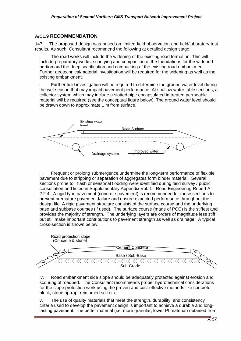
Preparation of Second Northern GMS Transport Network Improvement Project
A 57
A/C1.9 RECOMMENDATION 147. The proposed design was based on limited field observation and field/laboratory test results. As such, Consultant recommend the following at detailed design stage:
i. The road works will include the widening of the existing road formation. This will include preparatory works, scarifying and compaction of the foundations for the widened portion and the deep scarification and compacting of the existing road embankment. Further geotechnical/material investigation will be required for the widening as well as the existing embankment.
ii. Further field investigation will be required to determine the ground water level during the wet season that may impact pavement performance. At shallow water table sections, a collector system which may include a slotted pipe encapsulated in treated permeable material will be required (see the conceptual figure below). The ground water level should be drawn down to approximate 1 m from surface.
iii. Frequent or prolong submergence undermine the long-term performance of flexible pavement due to stripping or separation of aggregates form binder material. Several sections prone to flash or seasonal flooding were identified during field survey / public consultation and listed in Supplementary Appendix Vol. 1 - Road Engineering Report A 2.2.4. A rigid type pavement (concrete pavement) is recommended for these sections to prevent premature pavement failure and ensure expected performance throughout the design life. A rigid pavement structure consists of the surface course and the underlying base and subbase courses (if used). The surface course (made of PCC) is the stiffest and provides the majority of strength. The underlying layers are orders of magnitude less stiff but still make important contributions to pavement strength as well as drainage. A typical cross-section is shown below:
iv. Road embankment side slope should be adequately protected against erosion and scouring of roadbed. The Consultant recommends proper hydrotechnical considerations for the slope protection work using the proven and cost-effective methods like concrete block, stone rip-rap, reinforced soil etc.
v. The use of quality materials that meet the strength, durability, and consistency criteria used to develop the pavement design is important to achieve a durable and long-lasting pavement. The better material (i.e. more granular, lower PI material) obtained from
Existing water level
Drainage systemImproved water level
Road Surface
Cement Concrete
Base / Sub-Base Course
Sub-Grade
Road protection slope (Concrete & stone)

Preparation of Second Northern GMS Transport Network Improvement Project
A 58
excavated or other areas along the project road should be used in the upper part of embankment or fill areas. Appropriate material specifications should be prepared during detailed design stage.

Preparation of Second Northern GMS Transport Network Improvement Project
A 59
Annex 1: Summary of Subgrade DCP Test
Value of 5 top layers 3 lower layers Value of the whole layers DCP No.
location (Km)
Side Way (m) Thickness
(mm) DCP CBR (%)
Thickness (mm) DCP CBR
(%) Thickness
(mm) DCP CBR (%)
Equivalent CBR value
1 000+100 Lt/2.6 500.0 9.3 28.7 300.0 40.0 6.1 800.0 13.559 19.190 13.329
2 002+050 Lt/2.6 500.0 9.6 27.6 300.0 5.7 47.8 800.0 9.195 28.930 27.177
3 008+150 Rt/2.6 500.0 35.7 6.9 300.0 50.0 4.8 800.0 44.444 5.470 5.051
4 012+200 Rt/2.6 500.0 10.2 25.9 300.0 6.5 42.1 800.0 10.000 26.480 24.764
5 015+950 Rt/2.6 500.0 6.1 44.7 300.0 9.1 29.3 800.0 7.692 34.940 29.683
6 020+600 Lt/2.6 500.0 14.7 17.6 300.0 2.2 131.4 800.0 6.400 42.440 32.866
7 022+150 Lt/2.6 500.0 18.5 13.8 300.0 12.5 20.9 800.0 18.605 13.740 13.653
8 025+450 Lt/2.6 500.0 29.4 8.5 300.0 13.3 19.5 800.0 25.000 10.050 9.194
9 030+500 Lt/2.6 500.0 33.3 7.4 300.0 7.4 36.4 800.0 19.048 13.400 11.256
10 030+850 Rt/2.6 500.0 11.4 23.1 300.0 8.3 32.1 800.0 11.765 22.300 18.675
11 033+750 Rt/2.6 500.0 14.7 17.6 300.0 3.1 92.0 800.0 8.081 33.170 28.570
12 038+250 Lt/2.6 500.0 14.3 18.2 300.0 15.4 16.8 800.0 16.667 15.430 15.025
13 042+150 Rt/2.6 500.0 9.6 27.6 300.0 4.9 56.6 800.0 8.602 31.050 28.698
14 043+500 Lt/2.6 500.0 15.2 17.1 300.0 11.8 22.3 800.0 16.000 16.110 15.772
15 049+100 Rt/2.6 500.0 38.5 6.4 300.0 40.0 6.1 800.0 44.444 5.470 5.166
16 054+200 Lt/2.6 500.0 13.2 19.8 300.0 6.9 39.2 800.0 11.940 21.950 20.838
17 055+100 Lt/2.6 500.0 6.0 45.2 300.0 6.9 39.2 800.0 7.143 37.790 36.066
18 058+100 Rt/2.6 500.0 8.8 30.4 300.0 9.5 27.9 800.0 10.256 25.780 24.618
19 065+250 Rt/2.6 500.0 21.7 11.7 300.0 5.9 46.4 800.0 14.035 18.500 16.644
20 073+250 Lt/2.6 500.0 8.1 33.2 300.0 8.0 33.5 800.0 9.195 28.930 25.727

Preparation of Second Northern GMS Transport Network Improvement Project
A 60
Value of 5 top layers 3 lower layers Value of the whole layers DCP No.
location (Km)
Side Way (m) Thickness
(mm) DCP CBR (%)
Thickness (mm) DCP CBR
(%) Thickness
(mm) DCP CBR (%)
Equivalent CBR value
21 077+900 Lt/2.6 500.0 20.8 12.2 300.0 25.0 10.1 800.0 25.000 10.050 8.934
22 078+200 Lt/2.6 500.0 9.3 28.7 300.0 18.2 14.1 800.0 12.308 21.260 18.743
23 082+650 Lt/2.6 500.0 5.1 54.5 300.0 1.6 179.1 800.0 3.620 77.520 60.103
24 087+400 Rt/2.6 500.0 41.7 5.9 300.0 13.3 19.5 800.0 29.630 8.400 7.931
25 090+300 Rt/2.6 500.0 9.6 27.6 300.0 25.0 10.1 800.0 13.333 19.540 17.156
26 091+650 Rt/2.6 500.0 9.4 28.2 300.0 2.5 116.2 800.0 5.970 45.680 39.370
27 095+750 Rt/2.6 500.0 23.8 10.6 300.0 18.2 14.1 800.0 25.000 10.050 9.942
28 097+500 Rt/2.6 500.0 11.9 22.0 300.0 18.2 14.1 800.0 15.094 17.130 15.453
29 101+100 Rt/2.6 500.0 22.7 11.1 300.0 18.2 14.1 800.0 24.242 10.380 10.251
30 103+500 Rt/2.6 500.0 17.9 14.3 300.0 20.0 12.7 800.0 21.053 12.050 11.737
31 105+350 Lt/1.8 500.0 38.5 6.4 300.0 25.0 10.0 800.0 38.095 6.440 6.360
32 106+500 Lt/1.8 500.0 27.8 9.0 300.0 20.0 12.7 800.0 28.571 8.730 8.667
33 108+350 L/1.8 500.0 16.1 16.0 300.0 5.6 49.3 800.0 11.940 21.950 20.033
34 112+200 Rt/1.8 500.0 7.7 34.9 300.0 4.7 59.5 800.0 7.407 36.360 33.317
35 118+750 Rt/1.8 500.0 27.8 9.0 300.0 13.3 19.5 800.0 24.242 10.380 10.067
36 122+750 Lt/1.8 500.0 27.8 9.0 300.0 16.7 15.4 800.0 26.667 9.390 9.290
37 131+100 Rt/1.8 500.0 20.8 12.2 300.0 3.6 77.1 800.0 10.127 26.130 20.913
38 133+100 Rt/1.8 500.0 7.1 37.8 300.0 6.9 39.2 800.0 8.081 33.170 32.661
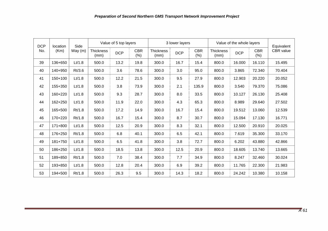
Preparation of Second Northern GMS Transport Network Improvement Project
A 61
Value of 5 top layers 3 lower layers Value of the whole layers
DCP No.
location (Km)
Side Way (m) Thickness
(mm) DCP CBR (%)
Thickness (mm) DCP CBR
(%) Thickness
(mm) DCP CBR (%)
Equivalent CBR value
39 136+650 Lt/1.8 500.0 13.2 19.8 300.0 16.7 15.4 800.0 16.000 16.110 15.495
40 140+950 Rt/3.6 500.0 3.6 78.6 300.0 3.0 95.0 800.0 3.865 72.340 70.404
41 150+100 Lt/1.8 500.0 12.2 21.5 300.0 9.5 27.9 800.0 12.903 20.220 20.052
42 155+350 Lt/1.8 500.0 3.8 73.9 300.0 2.1 135.9 800.0 3.540 79.370 75.086
43 160+220 Lt/1.8 500.0 9.3 28.7 300.0 8.0 33.5 800.0 10.127 26.130 25.408
44 162+250 Lt/1.8 500.0 11.9 22.0 300.0 4.3 65.3 800.0 8.989 29.640 27.502
45 165+500 Rt/1.8 500.0 17.2 14.9 300.0 16.7 15.4 800.0 19.512 13.060 12.539
46 170+220 Rt/1.8 500.0 16.7 15.4 300.0 8.7 30.7 800.0 15.094 17.130 16.771
47 171+800 Lt/1.8 500.0 12.5 20.9 300.0 8.3 32.1 800.0 12.500 20.910 20.025
48 176+250 Rt/1.8 500.0 6.8 40.1 300.0 6.5 42.1 800.0 7.619 35.300 33.170
49 181+750 Lt/1.8 500.0 6.5 41.8 300.0 3.8 72.7 800.0 6.202 43.880 42.866
50 186+250 Lt/1.8 500.0 18.5 13.8 300.0 12.5 20.9 800.0 18.605 13.740 13.665
51 189+850 Rt/1.8 500.0 7.0 38.4 300.0 7.7 34.9 800.0 8.247 32.460 30.024
52 193+850 Lt/1.8 500.0 12.8 20.4 300.0 6.9 39.2 800.0 11.765 22.300 21.983
53 194+500 Rt/1.8 500.0 26.3 9.5 300.0 14.3 18.2 800.0 24.242 10.380 10.158

Preparation of Second Northern GMS Transport Network Improvement Project
A 62
Annex 2: Summary of Test Pit Sample Tests in Laboratory
Plastic Index Compaction test result Density
N0.
Loca
tion
LL PL PI OMC MDD
Cal
iforn
ia B
earin
g R
atio
98%
Nat
ural
moi
stur
e,%
Soi
l,g/c
m3
Dry
S
oil,g
/cm
3
C
ompa
ctio
n ra
tio
Classifi -
cation by
AASHTO
1 Km0+100 37.2 22.1 15.1 16.00 1.889 15.00 20.61 2.396 1.986 105.2 A2 - 6
2 Km12+200 40.1 24.6 15.6 14.9 1.841 19.9 2.101 1.752 95.19 A2 - 7
3 Km22+350 39.9 22.4 17.5 15 1.851 42.06 1.801 1.267 68.47 A2 - 7
4 Km30+500 36.0 18.4 17.6 17.6 1.810 11.05 23.04 1.984 1.613 89.09 A2 - 6
5 Km42+150 38.0 20.9 17.6 13.8 1.799 22.62 2.147 1.751 97.33 A2 - 6
6 Km65+250 38.1 21.3 16.8 17.0 1.881 13.05 22.72 1.964 1.6 85.08 A2 - 6
7 Km78+200 36.0 23.6 12.5 15.9 1.901 25.87 2.155 1.712 90.05 A2 - 6
8 Km90+300 38.0 22.6 15.4 16.2 1.840 17.83 2.089 1.773 96.37 A2 - 6
9 Km101+100 36.5 20.5 16 17.7 1.801 14.00 16.66 1.863 1.597 88.68 A2 - 6
10 Km105+350 37.1 25.1 11.9 16.6 1.852 21.56 1.916 1.576 85.12 A2 - 6
11 Km112+200 36.9 21.6 15.3 15.0 1.901 15.02 27.26 1.7 1.336 70.26 A2 - 6
12 Km122+750 37.0 21.6 15.5 18.8 1.850 25.47 1.947 1.551 83.86 A2 - 6
13 Km133+100 38.0 21.4 16.6 16.6 1.989 20.00 A2 - 6
14 Km142+220 35.0 19 15.9 14.6 1.989 A2 - 6
15 Km151+150 35.0 19.6 14.5 13.6 2.010 12.45 2.31 2.054 102.2 A2 - 6
16 Km162+250 38.0 21.5 16.5 14.4 1.952 19.00 15.27 1.764 1.53 78.4 A2 - 6
17 Km170+220 37.0 23.6 13.4 17.4 1.901 14.86 2.165 1.885 99.13 A2 - 6
18 Km182+750 38.0 22.7 15.4 19.4 1.752 9.9 1.888 1.718 98.05 A2 - 6
19 Km193+850 42.1 23.5 18.6 15.4 1.920 16.05 17.66 2.096 1.782 97.68 A2 - 7

Preparation of Second Northern GMS Transport Network Improvement Project
A 63
Annex D of Part A Institutional - Vietnam
A/D 1 Introduction 148. While the primary thrust of the Project is to upgrade the main road and important connecting roads in the corridor, the benefits from this intervention will not be sustained unless adequate provisions are in place to maintain the roads after construction.
149. In Viet Nam the overall management of the Viet Nam national road network is the responsibility of the Vietnam Road Administration (VRA). Primary responsibility for ongoing maintenance lies with 4 Regional Road Management Units and for some roads Provincial Department s of Transport (PDoT). Maintenance works are carried out by government road management enterprises. A traditional norms-based approach is used for road planning, design, construction, maintenance and funding. In the case of QL 217, VRA have delegated the day to day management responsibility to the PDoT in Thanh Hoa. They have, with the agreement of VRA appointed two Road Management Units (RMU) to maintain QL217 and adjacent provincial and district roads. RMU1 is responsible for the eastern section of QL1 to km 104.7 while RMU2 is responsible for the western end through to Na Mao.
A/D 2 Problem Identification 150. There is a problem in both Viet Nam with roads being not maintained or inadequately maintained. As with road authorities the world over, the primary reason given is lack of money and ressources. However this may not be the whole answer. Investigation by the Consultant has found a number of factors that are contributing to the problem:
• Construction and maintenance work of poor quality leading to premature failure
• Planning and programming based on norms with the result that expenditure does not reflect needs (poor prioritization).
• Decisions made centrally based on inadequate or outdated data
• Excessive manpower in Viet Nam, resulting in significant budget going on wages
• Lack of appropriate equipment (eg graders for gravel roads)
151. The Governments in Viet Nam appear to recognize that there is an issue. With encouragement from the IFI, performance based contracting – which (in theory) places greater day-to-day responsibility in the hands of the contractor, had been adopted for some contracts in Lao PDR and is being trialed in Viet Nam.
152. There are plans to restructure the road maintenance units in Viet Nam as joint stock companies that would be able to compete with the private sector.
A/D 3 Performance Based Contracting
A/D 3.1 The Potential 153. Trials with PBC in Lao PDR and Viet Nam reflect a move internationally towards performance based maintenance contracts (PBC). In a full PBD contract, private sector contractors manage the road assets, leaving the road agency with responsibility for setting standards and overall network planning. A contract is awarded for a specified period ranging up to ten years for the maintenance management of a road. The contract

Preparation of Second Northern GMS Transport Network Improvement Project
A 64
specifies the standard to which the road is to be maintained, such as the surface condition with all potholes and edge-breaks to be repaired within 7 days, and it is up to the contractor to determine how that standard is best achieved. This places responsibility for asset management on the contractor.
154. The main advantage of PBC is that the contractor is able to optimize the maintenance work over the life of the contract. However this requires that the contractor has responsibility for all maintenance expenditures. In fact, PBC works by getting the right balance of periodic and routine maintenance. By getting this balance right, money is saved. PBC need to be long term to be effective – ten years or more thus covering at least one life cycle of periodic maintenance. This requires continuity of funding.
155. A PBC approach could lead to a more effective solution for the Project roads. For example while some bridges within Viet Nam require upgrading immediately, others are of relatively recent construction and have a number of years of useful life. Neither ADB nor PMU.1 has the resources to ‘micro-manage’ an optimal upgrading program. However a company with a PBC to reconstruct and manage the road over (say) a ten year period has all the right incentives to delay major expenditure where this can be achieved without loss of road performance.
156. An initiative being developed as part of the Viet Nam Road Network Improvement project (RNIP) will see the first Viet Nam PBC being tended in July with contracts being let in February 2010. The initiative is to pilot the concept by letting 3 contracts with lengths of 80 to 140 km on roads QL1 and QL10 covering a total distance of 300 km. The contracts cover initial upgrading and routine maintenance but only specified periodic maintenance. The project has modified the recommended WB documentation for PBC to accommodate the (perceived) situation in Vietnam and has included a system of penalties if monthly performance targets are not achieved.
157. The effectiveness of the initiative as a pilot to show whether PBC can deliver improved maintenance in a cost effective way will be difficult to judge as the scope of the contracts have been changed significantly from the initial concept.
158. One option for the Project roads is for the civil work is for the contracts to require the contractor to maintain the road for a period of 5-10 years after construction. This is a form of PBC and has the advantage that the company responsible for construction has an incentive to take a long term view. Further discussions with VRA and DOR will be held to identify the most suitable form of maintenance contract for roads upgraded under the Project.
A/D 3.2 Concerns with PBC 159. There is never perceived to be enough money for road maintenance: everywhere in the world road agencies struggle with less money than they think should be spent. This means that when it comes to setting up long term contracts – ie contracts covering more than a year and therefore more than one budget cycle, the total payments committed under the contracts can become an issue.
160. Other concerns raised include that the Project would be ICB and international bidders would not be interested in the maintenance component because the contract size is too small, while local companies have no relevant experience. Rates are expected to be far too high because bidders will internalize the risk – in particular if there are concerns about future payment they will ensure that their costs are returned in the first few years. There is a belief that the concept has failed elsewhere.
161. The solution most likely to address the various concerns and to achieve the potential of PBC is to encourage a joint venture approach between local and international

Preparation of Second Northern GMS Transport Network Improvement Project
A 65
companies. The international company would mobilize resources for the construction period and provide technological support for the local company over the contract duration. While this would not be attractive to some overseas companies who would prefer to come, build and move on, it would suit an international company that has/wants a long term presence in the country. In any case it will be necessary to have large enough areas under contract so that there is a ‘critical mass’ of work to interest the international company.
162. It may be possible for the invitation to tender to offer a choice of conventional or PBC to enable the government to chose based on the bids reeived. This will force bidders to make their PBC bids competitive with a conventional approach.
163. The concept of a Build and Operate PBC (or contract with extended maintence period) has been proposed before. One problem is that ADB loan funding is not normally available for maintenance. This is because ADB does not want loan money to be used for ‘consumption’ so there is nothing to show for the loan when it is due to be repaid. However when it is generally recognized that lack of maintenance is a major problem, it may be better to address this issue directly rather than attempt to ensure roads are maintained through the use of covenants.
164. ADB (or other donors) could asist in ensuring that PBC was successful by making some of the loan payable monthly (or as appropriate) during the maintenance period on evidence of payment to the contractor by the government. If the donor’s involvement with a country was a ‘one off’ it might be desirable for all the funding to be made available over a limited period. However for an agency like ADB that has a long term presence, an extended loan period should not create a problem.
A/C 4 Funding
A/D 4.1 The situation 165. In Viet Nam, funds are provided by the Central Government for maintenance works on national district and rural roads. The funds are funneled through Regional Road Management Units for most national highways and through provincial authorities, principally the Provincial Department of Transport (PDOT) for provincial, rural and some national highways. Funding for the project road is through the PDOT. Lack of adequate funds is an issue, although funding has been increasing by about 7% per year in recent years.
166. Main roads in Lao PDR are 100% funded through the Road Maintenance Fund while provincial roads are partly funded from the RMF. Funding is however not adequate and needs to be supported from external sources, even for the National Road Network. Lesser roads and minor highways are reported to receive little to no funds which means that they can become impassible during the wet season. This could change from 2010/11 with a significant share of the revenue from the NT-2 hydro power project being allocated for transport access improvements in poor rural areas.
A/D 4.2 The Issue 167. Funding is central to private participation in road maintenance. Commitment from the private sector will be hard to obtain unless there are reasonable long term prospects – this requires some certainty of funding. Lack of certainty increases risks. With public sector operators this risk manifests itself in higher than needed workforces and inefficient use of resources. With private sector operators it is reflected in high contract prices and unwillingness to bid.

Preparation of Second Northern GMS Transport Network Improvement Project
A 66
168. There is no point in setting up contracts with insufficient money. This is true both for the individual contracts and for the sector as a whole. It might be argued that if the budget is not sufficient to provide for periodic maintenance, the contracts should cover routine maintenance only and that when periodic maintenance is required it would have to be prioritized against other roads. This would be a mistake.
169. It is not possible to save money by optimising only part of the system. If the contractor has responsibility for routine maintenance but not for periodic maintenance, he has no interest in optimizing total expenditure. He will argue for more periodic maintenance than is optimal since this will reduce the routine maintenance cost. And if the periodic maintenance is not done, he will argue that this is a breach of contract since more routine maintenance is now required than allowed for in the contract.
170. If there really is insufficient money for periodic maintenance to maintain the roads in good condition, then overall funding priorities need to be sorted out before anything else. The question that needs to be asked is “which roads will be allowed to deteriorate”? At least for some roads, maintenance standards will have to fall so as to fit the budget constraint. If this is politically unacceptable, the only solution is to increase the maintenance budget. Any other action (such as cutting back on periodic maintenance) will make matters worse, not better.
A/D 4.3 Tolls 171. Bundling the revenue source with the construction and maintenance project, as is the case with BOT toll roads, can provide a way of providing a long term contract in circumstances where the government would be unwilling to commit to a long term maintenance only contract.
172. Tolls provide the most obvious and straight forward form of user charge. They establish a nexus between road use and payment; and between road use and maintenance expenditure. Tolls can be set to vary by vehicle type, time of day and journey length thus potentially providing economic signals to users. The main disadvantages are high transaction costs and the need (with conventional systems) for exit and entry control. They are seen as an option for major arterial routes such as the ring roads and for bridges, but not for the general road network. Tolls are often associated with private sector investment but can also be used independently as a source of government funds.
173. Viet Nam regulations requre tolls levied on government roads to be returned to the government. So while levying tolls on the project roads would improve the overall government finances, there is no guarantee it will lead to adequate funding of the roads themselves. To ensure the charges are used on the project road, this has to be under some form of BOT contract. A possible approach would be to use government and loan funds for the capital cost, but to make the maintenance component self financing to ensure that ongoing funding is available.
174. A conventional toll road approach would probably not be effective within Viet Nam. The project road has many alternatives, making tolls on one road alone unsatisfactory. While levying a road charge on vehicles crossing the border would be simple, it might compromise cross border transit negotiations if it is seen as penalizing vehicles from other countries. A border toll might also encourage transshipping which is less economic. It would be better to have a charge levied on all vehilcles using the project road.

Preparation of Second Northern GMS Transport Network Improvement Project
A 67
A/D 4.4 An Alternative User Fee 175. Another objection to raising revenue through tolls is that charges would discourage use of the new facility reducing the benefits from the project. This is certainly true of light vehicles because the marginal cost of providing for these vehicles is negligible. Charging for heavy vehicles is potentially economically justified if the charge regime reflects the road wear imposed. What is therefore proposed is a heavy vehicle maintenance fee designed to collect the cost of maintaining the road 3 . Since the ‘maintenance’ component of the contract would be met by users, there would be no need for an extended ADB loan process such as that discussed in section C1.
176. The fee could be paid at garages or designated shops. It could also be purchaced on the internet or by mobile phone. In Viet Nam it would need to apply to network of roads in the area, not just the main road – the solution may be to include the road network west of Cam Thui in the scheme. This would include feeder roads also being upgraded under the project. It would only apply to trucks. A truck would need to buy a permit for each trip it made or a period permit for (say) a week or a month.
177. Enforcement would be by the local police, who would keep any fines collected. Permits could also be checked at the border point.
A/D 4.5 Transfer to Private Sector (Vietnam) 178. While there is a policy of transferring road maintenance activities to the private sector in Viet Nam, this has yet to be implemented. Reasons include:
• The capabilities of the existing public service companies are greater than those of the private sector. This is to be expected as the private sector has not been involved in this sector
• The budget for maintenance is insufficient and the payment procedures are complicated
• The current form of contract does not give an assurance of continuity of work
• Contracting out existing work will lead to job losses for existing staff
179. These problems can be overcome if there is a planned transition to increased private participation. One possible transition path would be to structure RMU into units, each with specific contracts in place and then to sell the units complete with contract. The purchase agreement could include provision to convert the contract to PBC within a specified period. Another possible approach would be to require the successful tenderer to offer jobs to existing personnel.
3 Some engineers argue that road maintenance costs are largely ‘fixed’ and that the marginal cost is much lower than the average cost. This is not borne out by cross-section analysis of spending by road authorities which generally show maintenance expenditure proportional to heavy traffic.

Preparation of Second Northern GMS Transport Network Improvement Project
A 68
Annex E of Part A Rural Roads - Vietnam
A/E 1. Introduction and Methodology
General 180. Table A/E1.1 is a long list of the rural roads that have been identified, form the 77 road originally identified. As will ne noted many submissions did not include all the requested data and it there is a questions over the population data that was quoted (primarily group 3 and 5). This has largely been resolved, although there is still some doubt.
Screening Criteria 181. The screening process gave priority to roads which had restricted access (less than 12 months per year), to roads with a high poverty % and also road with the high number of poor people (poverty ratio X population). The lists were then refined further to exclude roads that were 1.5 km and less in length and also roads that were surfaced with gravel or were paved. While ethnic minorities % was not specifically a factor a high poverty rations also meant high % of ethnic minorities.
Table A/E1.1 Rural Roads Long List
Orig
inal
Can
dida
te
Num
ber
Dis
trict
Sta
rt P
oint
on
Ql2
17
End Point
Leng
th (m
)
Mon
ths
Roa
d Tr
affic
Terr
ain
Pop
ulat
ion
Min
or E
thni
c
Pove
rty R
ate
Ave
rage
Dis
tanc
e to
C
omm
une
Gro
upin
g 61
Ba Thuoc
Cau Dam
Lang San 4000 6 M 1000 100% 30% 4.0 1
62 Ba Thuoc Bai Tom
Lang Song 3000 6 M 500 100% 40% 4.0 1
63 Ba Thuoc
Dien Thai Mot Doi 3000 6 M 1000 80% 20% 0.5 1
16 Vinh Loc 36+680 Doi Thoi 2850 6 F 2300 20% 26% 4.1 1
60 Ba Thuoc La Han Lang Ca 9000 6 M 450 100% 40% 6.0 1
65 Ba Thuoc N/A Bo Ha 3500 6 M 450 100% 40% 3.0 1
66 Ba Thuoc N/A Buoc Bo 4000 9 M 400 100% 40% 2.0 1
69 Ba Thuoc N/A
Lang Nan 2500 0 M 100 100% 55% 2.0 1
8 Vinh Loc 15+900 Da But 5200 12 F 4920 0% 25% 4.0 1
13 Vinh Loc 24+955
Quang Bieu 2700 12 F 9700 0% 17% 2.0 1

Preparation of Second Northern GMS Transport Network Improvement Project
A 69
Orig
inal
Can
dida
te
Num
ber
Dis
trict
Sta
rt P
oint
on
Ql2
17
End Point
Leng
th (m
)
Mon
ths
Roa
d Tr
affic
Terr
ain
Pop
ulat
ion
Min
or E
thni
c
Pove
rty R
ate
Ave
rage
Dis
tanc
e to
C
omm
une
Gro
upin
g
74 Quan Son 133+000
Lang Tien 7000 12 M 3000 100% 70% 3.0 2
76 Quan Son 155+000 Ban Hau 6500 12 M 5000 100% 70% 6.0 2
77 Quan Son 167+000 Ban Bau 15000 12 M 4000 100% 70% 8.0 2
4 Ha Trung 7+800 Ha Son 16500 12 M 32000 4% 9% 2.6 2
39 Cam Thuy 63+350 Lang So 2500 12 M 10579 70% 20% 1.5 3
42 Cam Thuy 66+213
Trai Phong 3000 12 M 10579 80% 21% 1.5 3
43 Cam Thuy 67+135
Lang Cho 2500 12 M 12581 70% 21% 2.0 3
44 Cam Thuy 67+480 Lang Bui 2500 12 M 6007 70% 20% 2.0 3
47 Cam Thuy 70+400
Lang Ngoc 3200 12 M 10957 80% 32% 2.0 3
50 Cam Thuy 72+344
Phuong Khanh 9500 12 M 7968 80% 26% 7.5 3
51 Cam Thuy 73+200
Lamg Mot 5000 12 M 9218 80% 26% 4.5 3
52 Cam Thuy 73+450
Lang Ngoc 2500 12 M 8218 80% 26% 16. 3
21 Cam Thuy 38+900 Phuc Do 3200 9 M 38900 80% 19% 23.0 3
Selected rural roads 182. Selected rural roads are showing in Table A/E 1.2 Rural Roads short list. Engineering surveys including traffic survey have been one of variation factors. Figure A/E1.1 is showing selected rural roads map
Table A/E1.2 Rural Roads short List
No. Nummber of the Long list
Start point of QL217
R/L of QL217 Distinict End Point Length
(Km) Connects to
Road 1 4 7+800 L Ha Trung Chi Cuong 6.40 Provincial Road
to QL1A
2 4 7+800 R Ha Trung Gia Mieu 13.90 Provincial Road to QL1A
3 8 15+900 L Vinh Loc Xam 2 0.70 District Road
4 8 15+900 R Vinh Loc Da But 4.70 Provincial Road to QL1A
5 13 24+955 L Vinh Loc Quang Bieu 2.00 Commune Road to 217
No. Nummber of the Long list
Start point of QL217
R/L of QL217 Distinict End Point Length Connects to

Preparation of Second Northern GMS Transport Network Improvement Project
A 70
(Km) Road
6 16 35+300 R Vinh Loc Doi Thoi 2.20 District Road to 217
7 39 63+350 L Cam Thuy Lang So 2.20 None
8 42 66+213 L Cam Thuy Trai Phong 2.40 None
9 43 67+135 R Cam Thuy Lang Cho 3.70 None
10 48 70+740 L Cam Thuy Cam Lien 6.00 Provincial Road to 217
11 50 72+344 R Cam Thuy Phuong Khanh 10.20
to 217, and may connect to bridge crossing over Ma River in the future
12 52 74+100 R Cam Thuy Lang Ngoc 2.00 District Road
13 63 76+000 R Ba Thuoc Mot Doi 3.90 None
14 62 82+600 R Ba Thuoc Lang Song 10.00 District Road to 217
15 61 92+150 L Ba Thuoc Lang San 4.80 to 217
16 66 112+800 R Ba Thuoc Buoc Bo 4.00 None
17 74 133+000 L Quan Son Lam Phu 3.40 Provincial Road
18 76 154+200 L Quan Son Tam Lu 9.10 District Road
19 77 158+800 R Quan Son Nam Dong 17.90 Provincial Road
Total 109.50

Preparation of Second Northern GMS Transport Network Improvement Project
A 71
Figure A/E1.1 Rural Roads Map

Preparation of Second Northern GMS Transport Network Improvement Project
A 72
A/E 2. Road design standard General Regulations 183. Rural Roads are to connect to National Network for servicing Agriculture-Forestry-Fishbreeding productions, and Economic-Culture-Social exchanges. With Traffice Features are Medium Goods Vehicles, Light Goods Vehicles and Primitive Vehicles, and Fraggin
Design Period: Considering for the future
184. Rural roads connect between district and commune or commune to commune with various mechanical vehicles, demand high quality of Class 6 TCVN-4054-85. High technical quality standard should be build if possible.
185. Rural Roads connect commune to village and village to village demand 2 types of A and B.
186. Rural Road Type A is to used for vehicles with Single Axle Load of 60kN
187. Rural Road Type B is to used for vehicles with Single Axle Load of 25kN and priminitive vehicles
1. Technical Standards
1.1 Main Technical Elements Width
Formation Width
Pavement Mini. Horizontal Curve Radius
Max. Vertical Grade (MAPG)
Max. Length of MAPG Design
Categories (m) (m) (m) (%) (m) Class 5 Flat 7.5 5.5 60 7 600
Class 5 Mountainous 6.5 3.5 30 10 600
Class 6 Flat 6.5 3.5 30 9 400 Class 6
Mountainous 6 3.5 15 11 300
A 5,0 (4,0)* 3,5 (3,0)* 15 10 300
B 4,0 (3,5)* 3,0 (2,5)* 10 6 200**
Notes: * Amounts in brackets are minimum applying for poor condition and phasing investment ** Type B is to apply for primitive vehicles, so that the length should be limited
1.2 Widening Curves Width Formation Radius Widening Design Categories
(m) (m) (m)
Class 6 Mountainous 6.5 <15 and <25 2.2
A 5 >15 Not Applicable
B 4 10 1,0
1.3 Slope Type of Earth Embankment Excavation
Clay 1 / 1,50 1/0.75 - 1/1,00
Sand 1 / 1,75 -

Preparation of Second Northern GMS Transport Network Improvement Project
A 73
Type of Earth Embankment Excavation
Placed Rock 1/0,50 - 1/0,75 -
Soft Rock - 1/0,50 - 1/0,75
Hard Rock - 1/0,25 - 1/0,50
2. Pavement Design Standard 2.1 Type of Surfaces and Applications
Application No. Type
Class 5 and 6 A B
1 Cement Concrete M150 -200 +
2 Bituminous Surface Treatment + +
3 Stone with Cement Binder +
4 Placed Rock + +
5 Crushed Stone, Crushed Stone Aggregate, Stone Waste
+ + +
6 Limed Consolidate Soil and Gravel Pit. Sand and Gravel with Cement Binder + +
7 Gravel Pit
8 Gravel + +
9 Broken Brick, Baked Earth, Blast Furnace Cinder
+ +
10 Sandy Soil +
2.2 Minimum Thickness of Pavement Structure Application
No. Type Class 5 and 6 A B
1 Cement Concrete M150 -200 16
2 Bituminous Surface Treatment 1~4
(Bituminous) 12
3 Stone with Cement Binder 15
4 Placed Rock 20 12
5 Crushed Stone, Crushed Stone Aggregate, Stone Waste
N/A 12 10
6 Limed Consolidate Soil and Gravel Pit. Sand and Gravel with Cement Binder 15 12
7 Gravel Pit 15 12
8 Gravel 20 15
9 Broken Brick, Baked Earth, Blast Furnace Cinder
15
10 Sandy Soil 20

Preparation of Second Northern GMS Transport Network Improvement Project
A 74
2.3 Cross Fall,
- Carriage Way: 4%, - Shoulder : 5%.
3. Constructions 188. Bridge and culvert construction is recommended to be designed with permanent loads. Current Standards for bridges and culverts are to be used.
4. Pavement Engineer Recommendation: 189. This Standard is for Rural Road in Viet Nam issued in 1992, up to now almost pavements are to be used of binder. Base on current actual condition in Viet Nam, we suggest that using 2 only surface for pavements are: 1) Double Bituminous Surface Treatment
A/E 3. Proposed work of Rural Roads 190. Horizontal and vertical alignments of the selected rural roads have not been required any improving as preliminary TA consultant’s surveys. Proposed works of selected rural roads are showing in Table A/E 2.1 Proposed Work of Rural Roads. The proposed works are base on Rural Road Standard and engineering surveys.

Preparation of Second Northern GMS Transport Network Improvement Project
A 75
Table A/E3.1 Proposed Work of Rural Roads
No. Start point of QL217
R/L of QL217 Distinict End Point Length
(Km) Design
Standard Formation Width (m)
Pavement Work
Pavement Width (m) New Bridgs Box-Culvert/
Causeway
1 7+800 L Ha Trung Chi Cuong 6.40 VN6M 6.0 SBST 3.5
2 7+800 R Ha Trung Gia Mieu 13.90 VN5M 6.5 DBST 3.5 4 Bs–39.0m 4 Cel–8.0 m
3 15+900 L Vinh Loc Xam 2 0.70 RRB 4.0 SBST 4.0
4 15+900 R Vinh Loc Da But 4.70 VN6M 6.0 SBST 3.5 1 B–15.0m
5 24+955 L Vinh Loc Quang Bieu 2.00 RRB 4.0 SBST 3.0
6 35+300 R Vinh Loc Doi Thoi 2.20 VN6M 6.0 SBST 3.5
7 63+350 L Cam Thuy Lang So 2.20 RRB 4.0 SBST 3.0
8 66+213 L Cam Thuy Trai Phong 2.40 RRB 4.0 SBST 3.0
9 67+135 R Cam Thuy Lang Cho 3.70 RRB 4.0 SBST 3.0
10 70+740 L Cam Thuy Cam Lien 6.00 VN6M 6.0 SBST 3.5 2 Bs–11.0m
11 72+344 R Cam Thuy Phuong Khanh 10.20 VN6M 6.0 SBST 3.5 2 Bs– 7.0m
12 74+100 R Cam Thuy Lang Ngoc 2.00 RRB 4.0 SBST 3.0
13 76+000 R Ba Thuoc Mot Doi 3.90 RRA 5.0 DBST 3.5 2 Cel–4.0 m
14 82+600 R Ba Thuoc Lang Song 10.00 RRA 5.0 DBST 3.5
15 92+150 L Ba Thuoc Lang San 4.80 RRB 4.0 SBST 3.0
16 112+800 R Ba Thuoc Buoc Bo 4.00 RRB 4.0 SBST 3.0
17 133+000 L Quan Son Lam Phu 3.40 RRA 5.0 DBST 3.5
18 154+200 L Quan Son Tam Lu 9.10 RRA 5.0 SBST 3.5 5 Bs– 48.0m
19 158+800 R Quan Son Nam Dong 17.90 VN6M 6.0 DBST 3.5 2 Bs– 7.0m
Design Standerd : VN5F-Class 5 Flat ,VN6F-Class 6 Flat, VN5M-Class 5 Mountainous, VN6M-Class 6 Mountainous RRA- Rural Road Standard Class A Briodge/ Box-culvert : 4 Bs – 39.0m = 4 bridges, 39.0 m total length of bridges, 4 cel – 8.0m = Toata 4 cells, 8.0m cells length

Preparation of Second Northern GMS Transport Network Improvement Project
A 76
A/E 4. Cost Estimate
General 191. Cost estimate has been prepared to obtain the project quantities for civil works and project cost for economic evaluation. These are summarized below Table A/E4.1- Cost of Proposed Work.
192. The unit rates were estimated as of 2009, and compared with latest contracts in Vietnam, and then adjusted to reflect expected costs in 2012. As the inflation rates have been 10% for three years (3) and this is expected
Table A/E4.1 Cost of Proposed Work
2012 US$ No. Start points
on QL217 Length (km)
2009 Net US$ Net Contingency Tax Total
1 7+800 L 6.40 615,402 819,100 81,910 90,101 991,1112 7+800 R 13.90 1,368,066 1,820,896 182,090 200,299 2,203,2853 15+900 L 0.70 36,585 48,695 4,869 5,356 58,9214 15+900 R 4.70 567,968 755,965 75,597 83,156 914,7185 24+955 L 2.00 79,947 106,410 10,641 11,705 128,7566 35+300 R 2.20 162,223 215,919 21,592 23,751 261,2637 63+350 L 2.20 122,334 162,826 16,283 17,911 197,0208 66+213 L 2.40 321,686 428,165 42,816 47,098 518,0799 67+135 R 3.70 250,199 333,015 33,301 36,632 402,94810 70+740 L 6.00 470,923 626,799 62,680 68,948 758,42711 72+344 R 10.20 754,838 1,004,689 100,469 110,516 1,215,67312 74+100 R 2.00 92,301 122,852 12,285 13,514 148,65113 76+000 R 3.90 452,260 601,958 60,196 66,215 728,36914 82+600 R 10.00 556,318 740,460 74,046 81,451 895,95615 92+150 L 4.80 334,029 444,593 44,459 48,905 537,95716 112+800 R 4.00 246,118 327,583 32,758 36,034 396,37616 133+000 L 3.40 187,459 249,509 24,951 27,446 301,90518 154+200 L 9.10 877,271 1,167,647 116,765 128,441 1,412,85319 158+800 R 17.90 2,914,171 3,878,761 387,876 426,664 4,693,301
Total 109.50 10,410,099 13,855,841 1,385,584 1,524,143 16,765,568

Preparation of Second Northern GMS Transport Network Improvement Project
B 1
Part B - Lao PDR
B1.0 Project Roads
B1.1 General 193. This report makes up one volume of the Supplementary Appendix to the Main report. Some of the analysis presented in Part B of this volume (Volume1) is based on data and analysis presented in other volumes, These are listed in B1.3 below.
194. The project road in Lao PDR is part of the North Eastern economic corridor for the Greater Mekong Sub-region (GMS) Economic Cooperation Program. The project road length is 350 km of which 143 km is to be upgraded. A further 206 km are to be considered for possible alignment improvements. In order to maximize the Project benefits to the people the TA has also prioritized 100 km of rural access roads for improvement to extend the benefits of the corridor improvements to the hinterland.
195. The road lengths in Laos PDR (LAO) consist of 56 km of road R6 between Vieng Xia and to the border with Vietnam at Nam Soi, 62.5 km of road R6A between Hang Long and Sop Bao, and 25 km of road R6B between Sao Bao and the border with Vietnam at Pahang. Further to the above the study has also to identify sections with poor alignment, on road R1C between Muang Kham and Phoulao, and 114 km of road R6 between Phoulao and Vieng Xai, excluding the section through Xam Nua.
196. The start and end of each road sections are as follows:
Sections to be Upgraded • R6 (Vieng to Nam Soi) - Km 119 to Km 175.02;
• R6A - from intersection with R6 to Km 62.55 (joins road rehabilitation works carried out by KfW);
• R6B - Intersection with R6A to road QL 43 (Pahang);
Sections to be checked for alignment improvements • R1C - Intersection with R7 to Intersection with R6; and
R6 - Intersection with R1C (Km0) to Km 119 (Viengxai).
B1.2 Road Engineering Surveys 197. Surveys carried out during the project were as follows:
• GPS center line surveys - used to define/show the general alignment characteristics of the alignment. Refer to Supplementary Appendix Volume 10 Drawings, for the road plan and profile;
• Road inventory and conditions surveys - provided information on the physical road characteristics, key condition indicators, location and extent of towns, drainage details, terrain type and cross sections details (height of cut/fill, slope, etc). Data was used to characterize the road condition, identify location of cross section changes, and to calculate earthworks, and drainage structure replacements, etc. Annex B/Part A includes a sample road condition and inventory sheet. Results are summarized in Table B 2.2.3 below with other road condition data ;
Preparation of Second Northern GMS Transport Network Improvement Project
B 2
• Work needs field assessments - a field assessment to identify the extent and side for the centerline shift for the proposed road upgrading;
• Traffic surveys, including - classified counts and origin/destination surveys - conducted at 5 locations. Details are presented in Supplementary Appendix Volume 5.;
• Test pits and material source investigations and laboratory surveys - 20 test pits and 60 DCP measurements were made (20 at the site of the test pit). This data provided details of the existing pavement structure and also the subgrade conditions (density, moisture content and variations in strength/densities along the road and also with depth). Results are summarized in Annex C of Part B; and
• Road safety audits - intended to identify road safety issues along the road, that could be corrected through road improvements.
198. The above list excludes the bridge, social, environmental and resettlement surveys which were carried out and reported in the appropriate Supplementary Appendix volumes.
199. Deflections surveys were not carried out because the length of paved road was relatively small and that which was paved was narrow and would need to be reconstructed in a few years.
B1.3 Project documentation 200. The project engineering report are contained in the following supplementary appendix volumes:
Volume 1 Road engineering (including pavement and cost estimates);
Volume 2 Bridge engineering;
Volume 9 Road Safety Audit
Volume 10 Procurement Documents; and
Volume 11 Drawings.
201. The bidding documents consist of the following:
· Request for Bid;
· General and specific conditions of contract
· Specification (standard and special)
· Bill of quantities;
The drawings include:
· Plan and profile of the existing alignment with locations of culverts and bridges indicated;
· Tables showing location and details of bridges and culverts;
· Table showing offsets from the existing to the proposed new alignment;
· Table showing location of curves improvements; and
· Detailed drawings of intersections, bridges, and
· Nam Ma river crossing improvements.
Preparation of Second Northern GMS Transport Network Improvement Project
B 3
B2.0 Project Road Characteristics
B2.1 Road Management and Maintenance
B2.1.1 Management and Operations 202. The MPWT is responsible for the management/coordination of 37790 km (13% paved) of road of which 7255 kilometers are national highways, for which the MPW has a direct responsibility. It is assisted in this tasks by the provincial DPWTs located in each province who are also responsible for the provincial network which includes provincial, district, urban and rural roads. The DPWT in each province reports to the MPWT on national road and technical (including standards) matters and to the Provincial Governor on provincial road matters. A more complete set of road lengths is shown in Annex C.
203. The system in Lao PDR is center based with all key decisions relating to the national highway being determined by the MPWT. Provincial DPWT appear to have a limited say in the identification of works prior to budget approval. The works are largely identified by a Road Management System (RMS) using data that is presently not always accurate nor is it necessarily current4. The DPWTs are responsible for implementing road maintenance programs in the province. In the case of road maintenance of national roads the work is outsourced to the private sector for contract periods of 3 years. This is however limited to the 2900 km of roads that are new or in good or in good condition5. Elsewhere the maintenance work is minimal, often limited to works required to keep a road open to traffic.
204. Of the roads directly administered by MPWT, 435 km are surfaced with asphalt concrete (AC) and 3530 km with Double Surface Treatment (DBST)). The balance consist of 2457 kilometers of gravel road and 800 km of earth road. Many of the latter are reported to be in poor condition or seen as “un-maintainable”.
B2.1.2 Road maintenance funding 205. Funding of road maintenance has become a more important priority in recent years. Funding is however not adequate and needs to be supported from external sources, even for the National Road Network. Lesser roads and minor highways are reported to receive little to no funds which means that they can become impassible during the wet season. This could change from 2010/11iwith a significant share of the revenue form the NT-2 hydro power project being allocated for transport access improvements in poor rural areas.
206. Recent road budget allocations for the roads managed by the MPWT are presented in Table B2.1.1 below. The expenditure was equal to approximately US$ 9700 per kilometre 6 of national road maintained by the MPWT, in 2009. Given that approximately 55% of the national road network are unpaved, the funding levels are 4 This was found to be the case on the project roads in Lao PDR. RAMs data was accessed early in the project. 5 Approximately 2800 km by December 2008. Contracts were a mixture of PBC (requirements not tough and also not always enforced) and schedule of rates. Funding allocations for 2 sections of road R6 in Houaphan were USD 1400 and 2000 per kilometer per year for routine and emergency (small scale) maintenance work 6 This figure is calculated by dividing the annul budget by the length of the network managed or maintained by the road authority (MPWT in Lao PDR).

Preparation of Second Northern GMS Transport Network Improvement Project
B 4
moderately high7, after allowance is made for the fact that Lao PDR is spending a higher percentage of their budget on upgrading that is the case in developed countries.
207. Routine and periodic maintenance programs are presently still largely reactive except possibly for vegetation control. This means that the needed repair works are more extensive and expensive. There is a need for the addition of a stronger preventive8 maintenance philosophy to the present maintenance road maintenance program.
Table B2.1.1 - Lao PDR Road and Maintenance Funding (US$, millions) 2006 2007 2008 2009 Lao PDR Budget
Road Rehabilitation, upgrading and construction 5.76 5.25 3.76 5.25
Road maintenance and repair 9.03 13.17 17.16 25.59
Total Domestic 14.78 18.42 20.92 30.84
External (Loans and Grants) Funds
Road Rehabilitation, upgrading and construction 31.56 76.07 54.95 49.82
Road maintenance and repair 6.67 4.39 2.79 8.32
Total External 38.23 80.46 57.74 58.14
Total Road Expenditure 53.02 98.88 78.66 88.98
% Upgrading and construction 72% 81% 73% 65%
% Spent on National Roads 95% 95% 90% 78%
Expenditure on NR USD /Km (approx) 6993 12990 9879 9670
Source: MPWT (Disbursement Division of Department of Roads). Above values are for routine maintenance, and some limited periodic maintenance
B2.1.3 Road management and maintenance systems and initiatives
Road management system 208. The Road Management System (RMS) and the Bridge Management System (BMS) established a few years ago has been modified to hold and analyze rural roads data. The new system, known as Unified Road Management Framework (URMF) was developed in 2008 and has been used in the development of the strategic plan for the
7 Countries like Australia and Canada spend the equivalent of approximately US$ 11,000 per kilometer per year7 , excluding the costs associated with mega projects (tunnels, expressways, etc) 8 Preventive maintenance is largely an variation of routine and periodic maintenance works but carried out at the right time (Eg. sealing hairline cracks before they develop into a pothole, resealing for sprayed and slurry seals before existing seals develop cracks, etc). It also include ensure that designs do not build in maintenance problems (an issue in Vietnam and Lao PDR).
Preparation of Second Northern GMS Transport Network Improvement Project
B 5
Lao Transport Sector Program (LTSP) a program that will follow on from the World Banks “Road Maintenance Porgram2” project.
209. The system is designed to assist the MPWT develop strategic as well as annual plans that will allocate funds to the various road categories and areas of greatest need. This includes routine maintenance funding. The system is operated by the Public Works and Transport Institute. While HDM4 is used for analysis it was noted that those charged with operating the system could not explain the RMS or URMF) system. Further the data provided from the system was found to be of questionable accuracy, a factor that appeared to be well known within the road community. This raises some question about the sustainability of the system in the medium to long term.
Contracted road maintenance 210. Changes in the traditional approach to road and maintenance management have been partially successful with maintenance works on a significant length of the national highway network now outsourced to the private sector., and use is being made of a computerized road management system to develop annual programs and forward strategies. Neither the outsourcing or the computerized systems are working as well as they should. The lack of adequate funding, inexperienced contractors, simplistic contract documents, small road networks and poor quality control/enforcement are some of the reasons. Some are being addressed by other ongoing and proposed assistance program.
211. Having said the above the contract approach has only been used for a short time and some of the deficiencies in the approach have been identified, although not acted on as MPWT are still looking for possible solutions. Their focus is on improving/strengthening specifications/contracts and also enforcement. Should progress be made in this area some of the deficiencies of the present system will have been addressed, but only some.
212. In the project area road R6 is under covered by 2 performance based maintenance contract, the first between Km 0 and 92 and the second between Km96 an 119. A quick review of the second contract showed that it was essentially a “schedule of rates” contract where the DPWT identified the works monthly, which were then completed by the contractor. The contractor was not on site full time but mobilized maintenance crews when required.
B2.2 Road characteristics
B2.2.1 Project Road Description
R6 - Viengxai (Km 119) to NamSoi 213. Road R6 was upgraded to a Class 5 paved road standard in 1999/2000 for its whole length. Subsequent works completed in 2007 between km 94 and Km 119 saw the 25 km section between outskirts of Xam Nua town and Viengxai upgraded to a class 4 standard, KfW funded this work . The present road condition ranges varies from good to very poor especially the last few kilometers before Namsoi where the road has failed, rut depths are more than 50 mm and potholes and failing areas cover more than 50 % of the pavement surface. As a general rule it is estimated that the pavements would need to be rehabilitated within 1 to 4 years.
214. The road is largely located in difficult terrain with the horizontal alignment, on a few occasions (hairpin bends in association with steep grades) reducing speeds to less than 20 kph. Generally however the alignment is a 40 kph (average) road. As is typical n

Preparation of Second Northern GMS Transport Network Improvement Project
B 6
this type of terrain however the vertical alignment has a greater impact on travel speed than the horizontal.
215. The road section to be upgraded is located between Km 28 from Xam Nua (Km119 from the start of the road) and the start of the border area facility (which includes extensive parking areas) located at Km 83.2 from Xam Nua (Km 175.02). Refer to bidding documents included as a Supplementary Appendix.
Road R6A - R6 Km Sop Bao 216. The road section to be upgraded is located between immediately north of the roads intersection with R6 and the recently completed road works in Sop Bao, an overall distance of 62.4 Km. KfW completed the rehabilitation/upgrading of the section through Sop Bao in March 2009. The road consists of a 3.5m to 4m seal (bitumen macadam) on a 5.5m to 6m formation width for the first 10 kilometers. The road then reverts to a gravel/earth surfaced road with some badly damaged sections of macadam pavement whose presence often makes road conditions much worse, often reducing travel speeds to as low as 10 kph. While the alignment in the mountainous section is largely dictated by the terrain that in the flat terrain is largely controlled by the presence of villages/settlements.
217. The horizontal alignment is generally of a poorer quality in the hilly terrain as the road follows the terrain which means that allowable speeds for light vehicles are reduced in most instances to speeds of 20 to 50 kph, but are as low as 10 kph and as high as 80 kph in the flatter terrain if the ride quality where acceptable, as the road is often straight. Trucks speeds are, as would be expected 15 to 20 kph lower especially in the steeper terrain. Refer to Supplementary Appendix Volume 8 for details of the alignment.
218. The vertical alignment varies from mild to steep as the road passes through undulating to hilly terrain, at the start of the road before descending to the valley formed by Nam Ma which the road parallels through to Sop Bao. In the valley the road often follows the natural rise and fall of the road because there is often minimal earthworks. Where the road passes through rice growing areas the road is therefore subject to saturation and possibly short term localized flooding.
Road R6B - R6A (Sop Bao) to Pahang (connects to QL43 in Vietnam) 219. The road section to be upgraded is located between R6A at Sop Bao and the Pahang on the border with Vietnam, a distance of 25 km. The crossing of Nam Ma is adjacent to the start of the R6B as road R6A is located immediately adjacent to the Nam Ma. The alignment of the first section of R6B and the relevant section of R6A will be effected by the solution developed for the crossing of Nam Ma. East of the river the road follows the terrain and while relatively flat it is initially located in hilly terrain which means that the horizontal alignment is typical of that found on R6 and R6B as discussed above.
220. The road is surfaced with gravel for a width of 4.5 metres on a formation that is typically between 5.5 and 6 metres. The horizontal alignment is generally of a poorer quality in the hilly terrain as the road follows the terrain which means that allowable speeds for light vehicles are reduced in most instances to speeds of around 25 kph but are as low as 15 kph where ride conditions are poor and could be as high as 70 kph in the flatter terrain, if ride conditions were good and the roads are straight. Trucks speeds are, as would be expected 15 to 20 kph lower especially in the steeper terrain. Refer to bidding documents included as Supplementary Appendix 11.
Preparation of Second Northern GMS Transport Network Improvement Project
B 7
Alignment improvement sections
Road 6 General 221. The project has examined the road section between Viangxa1 and Phoulao and also that between Muang Kham and look for possible road alignment opportunities. The inspection showed that while there was a need for some alignment improvements the combination of tight curves with steep grades meant that it was difficult to many opportunities for alignment improvement. At best, the horizontal alignments could be moved by around 10 metres, but often less. Possible improvements, that range from curve widening to small alignment improvements are more likely to be possible and will have the effect of improving travel speed by improving the sight distance and also widening the road sufficiently to allow two vehicles to pass on even the tight curves, presently not possible because the road widths do not allow this to happen without one of the vehicle having to stop,
Phoulao to Sam Nua (Km 90 - Southern Xam Nua City boundary) 222. The alignment investigation showed that the speed, when averaged over the full length of the Viengxai and Phoulao section was 45 kph, which was similar to that between Muang Kham and Phoulao.. Travel speed observed around the worse curves were around 25 to 30 kph, but generally in excess of 40 kph. Refer to the alignment drawings included in Supplementary Appendix Volume 8 for details of the alignments.
Road Description 223. Road 6 was rehabilitated by the MPWT with the assistance of KfW in 2000 and 2001 to a Class 5 standard which consists of a 5 meter seal with 0.5 to 0.75 meter shoulders . Since construction the road has been resealed and been repaired annually for the last few years. Most of the repairs are in the outer wheel path which is often found where there is poor pavement subsoil drainage as occurs where the boxed pavement construction approach has been used, which means that life cycle costs are higher because of a shorter pavement life and the need for more repairs.
224. The present road conditions are poorer than one would expect for a road that is approximately 7 to 8 years old and carried less than 50 commercial vehicles per day . It is however typical of pavement performance in Laos.
225. While poor work quality is though to be a major issue for poor pavement performance, the other significant reasons include inadequate pavement thickness because of inadequate/improper investigations and analysis and/or inadequate provision being made for drainage, and/or substandard material being used, often in the subbase layer.
226. A visual assessment pavement indicates that the pavement life is between 2 to 5 years with a further 2 to 5 % of the road needing to be repaired within the next 12 months. This assumes the existing traffic conditions.
Improvement works options 227. Possible improvements include the following:
• Increasing curve radius - by cutting into the hill or by filling across drainage lines. The latter option is only possible where the drainage lines is flat enough to construct a fill (this means only a few locations;

Preparation of Second Northern GMS Transport Network Improvement Project
B 8
• Widening of pavement on curves - this is required, especially on the tight curves to allow vehicles to pass safely. The widening could be as much as 8 metres on the tight hairpin curves;
• Passing bays on steep and long grades; and
• Escape safety ramps that could be used by drivers who loose control of their trucks. They would be constructed at suitable locations.
Improvement works implementation 228. The improvement works are best carried out by local contractors as most of the works are spread out and lend themselves to a low scale operation, which can be implemented over a few years. Further, as there are existing maintenance contracts the improvement works could be added to the maintenance contracts for the road sections in question when the contracts are next tendered.
Xam Nua (Km94 - Northern City boundary) to Viengxai (Km 119)
Road Description 229. Unlike the section south of Sam Nua the road was rehabilitated between mid 2006 and early 2007. The expected life of the pavement and the seal is therefore around 5 to 7 years. The opportunities for improving alignment occur more often then the preceding section because the road passes through more flat to rolling terrain. As discussed earlier, the improvement while possibly not individually significant they will improve the sight distance, thus improving road safety and operating speeds.
Improvement works options 230. As proposed above for the sections to be upgraded.
B2.2.2 Road Alignment 231. Details of the alignments of the project road sections can be seen in the plans and profiles included in Supplementary Appendix Volume 8.
B2.2.3 Existing Pavement Characteristics 232. Road 6B is 24 kilometers long from its junction with R6A to the Lao PDR / Viet Nam border. The road is gravel and it varies in condition from average to very poor, especially at the eastern end where there are remnants of an old macadam pavement and also an earth section with ruts that are more than 100 mm. Except for short sections of flat to rolling terrain where the alignment is reasonable, except for some curves, the road alignment is controlled by the mountainous terrain.
Road condition 233. Pavement conditions on the Lao roads can be described as follows:
• R6 - road pavement conditions vary significantly from good to very poor with the majority of road sections being rated as fair to poor. This rating is based primarily of the remaining life of the surfacing and also estimated structural life. The former based on a visual assessment of surface texture and cracking and the latter based on the extent of repairs, present failures and rut depth and roughness. A summary of conditions is presented in Table 2.2.3 below;

Preparation of Second Northern GMS Transport Network Improvement Project
B 9
• R6A (10 kilometer paved road section) - paved conditions varied greatly with roughness levels being from IRI 6 to 12, most sections had a roughness of IRI 7 to 9;
• Unpaved road sections on R6A - ride conditions are generally fair to poor with IRI levels of 8 to 15 plus. At time vehicle speeds were reduced to 10 kph;
• Unpaved road sections on R6B - ride quality varies significantly with most having an estimated IRI of between 8 and 15 plus. Complete pavement and subgrade failures are also present with rut depths exceeding 10 cm for a number of kilometers. Macadam pavement section towards the eastern end of the road are badly damaged with estimated IRI of more than 15. The macadam sections are present for approximately 4 kilometers
234. Refer to Table B2.2.3 for a summary of the road characteristics.
B2.2.4 Wet and flooded sections 235. The road sections which are subject to flooding are listed in Table 2.2.1 below. Sections where the road is located below the level of rice fields which are located immediately adjacent to the road, resulting in wet conditions are identified in Table B2.2.2 below.
Table B2.2.1 Summary of Sections Subject to Flooding
Location Road No Duration (hour)
Flood length (m)
Frequency (time/year)
Km 113+200 Khongseep et Village R6 10 20 1
Km 129+500 Namon Village R6 72 180 3
Km 130+500 Namon Village R6 72 180 1
Km 131+500 Narcown Village R6 3 15 1
Km 142+000 Need Bong Mountain R6 1 10 1
Km 162+000 Phoumai Village R6 2 10 1
Km 165+000 Som Village R6 3 15 1
Km 165+500 Som Village R6 3 15 1
Km 60+000 Muang hom Village R6A 96 200 1
Source: Department of Public Works and Transport, Houaphan province
Table B2.2.2 Summary of Wet/Saturated Sections
Road Location Comment
6Â 44.5 to 50 Road at, below and slightly above natural surface - Rice field
6A 51 to 51 .9 Low fill – rice cultivation
6B 11.8 to 14.3 Soft ground – weak subgrade - hilly terrain - deep ruts

Preparation of Second Northern GMS Transport Network Improvement Project
B 10
B2.2.5 Slope stability 236. Problem slope stability areas have been identified, the observed locations were on road R6 at km’s 18.5, 21.4, 24.6 and 38.3, in most instances, the problem will be small slips.
237. The gentler slope and incorporated banquettes are proposed. Allowance is made in the BoQ however for retaining walls at location that will need to be identified in the detailed design phase. Typical section is shown Figure A2.2.2 below.
Figure B2.2.1 Typical section for Slope stability
B2.2.6 Traffic
Traffic Data 238. Traffic count details for the years 2006 to 2008 are presented in the traffic analysis section of Supplementary Volume 5 Traffic Analysis, Forecast and Economic Analysis. A summary of data for 2009 is presented below in Table B2.2.4. The table also includes the total PCU,s for each location.

Preparation of Second Northern GMS Transport Network Improvement Project
B 11
Table B2.2.3 - Lao PDR Project Road Characteristics
From (Km)
To (Km)
Length (km)
Terrain
Altitude
Present Road
StandardYear
Rehab Existing
SN Possible Alternate Alignment
Pavement Width
(m)
Shoulder Width
(m) each side
Surface Type
Rough-ness (IRI)
Crack (%)
Rut depth (mm)
Patch-ing (%)
CBR (%)
Curvature
Rise and fall
119 121.46 2.46 R 860 L6 2000 1.50 NO 3.8 1 Sprayed Seal 5 20 10 20 46 300 60
121.46 126.69 5.23 R 760 L6 2000 1.50 NO 3.8 1 Sprayed Seal 5 20 25 20 21 250 55
126.69 131.31 4.62 R 720 L6 2000 1.50 NO 3.8 1 Sprayed Seal 5 20 15 20 16 260 55
131.31 141.67 10.36 H 660 L6 2000 1.50 NO 4 1 Sprayed Seal 5 20 15 20 28 280 55
141.67 152.54 10.87 H 650 L6 2000 1.50 NO 4.5 0.75 Sprayed Seal 5 20 15 20 25 220 50
152.54 158.59 6.05 H 540 L6 2000 1.50 NO 3.5 0.75 Sprayed Seal 5 20 15 20 37 350 80
158.59 169.26 10.67 H 420 L6 2000 1.50 NO 4 0.5 Sprayed Seal 5 20 20 35 19 200 50
Roa
d 6
169.26 175.00 5.74 H 370 L6 2000 1.50 NO 4 0.5 Sprayed Seal 7 20 25 45 - 380 50
0 1.22 1.22 H 850 L6 2000 1.5 NO 3.5 0.75 Sprayed Seal 5 15 10 15 - 200 70
1.22 11.16 9.94 H 740 l6 2000 1.5 NO 3.5 0.75 Sprayed Seal 5 15 10 15 25 300 70
11.16 20.09 8.93 H 650 L6 1995 0.5 NO 5.5 0 Gravel 7 0 0 0 - 250 50
20.09 22.12 2.03 H 580 L6 1995 0.5 NO 5.5 0 Gravel 10 0 0 0 54 150 40
22.12 24.86 2.74 H 550 L6 1995 0.5 NO 5.5 0 Gravel 10 0 0 0 - 380 135
24.86 34.70 9.84 H 450 L6 1995 0.5 NO 5.5 0 Gravel 10 0 0 0 - 120 35
Sect
ion
6A
34.70 36.83 2.13 H 340 L6 1995 0.5 NO 5.5 0 Gravel 8 0 0 0 - 380 65

Preparation of Second Northern GMS Transport Network Improvement Project
B 12
From (Km)
To (Km)
Length (km)
Terrain
Altitude
Present Road
StandardYear
Rehab Existing
SN Possible Alternate Alignment
Pavement Width
(m)
Shoulder Width
(m) each side
Surface Type
Rough-ness (IRI)
Crack (%)
Rut depth (mm)
Patch-ing (%)
CBR (%)
Curvature
Rise and fall
36.83 62.40 25.57 H 250 L6 1995 0.5 NO 5.5 0 Gravel 8 0 0 0 13 100 40
0 9.96 9.96 H 400 L6 1995 0.5 NO 5 0 Gravel 8 0 0 0 40 180 40
9.96 10.86 0.90 H 500 L6 1995 0.5 NO 5 0 Mac Failed 12 100 20 70 - 230 40
10.86 19.58 8.73 H 750 L6 1995 0.5 NO 5 0 Gravel 8 0 0 0 16 200 40
19.58 23.64 4.06 H 1150 L6 1995 0.5 NO 5 0 Mac Failed 15 100 20 50 35 420 75
23.64 24.86 1.22 H 1300 L6 1995 0.5 NO 5 0 Gravel 10 0 0 0 - 500 105
Sect
ion
6B
Terrain: P-Plain, R-Rolling, H-Hilly
CBR: Surveyed minimum value in top 3 layers

Preparation of Second Northern GMS Transport Network Improvement Project
B 13
Table B2.2.4 - 2009 Traffic Data
Location (Km)
Motor cycles
Passenger Car Pickup Small
TruckMedium Truck
Heavy Truck
Very Heavy Truck
Medium
Bus
Large Bus Total PCU
R6 (Km 119 to 163 309 2 47 32 15 11 2 9 3 430 301
R6 (Km 163 to175 20 8 9 0 4 14 0 1 0 56 33
R6A - Km 0 to 33
143
2 47 9 10 5 0 4 7 227 143
R6A - Km 33 to 62.5 420 2 46 26 8 5 0 3 7 517 239
R6B - Km 0 to 25 11 1 16 0 6 7 0 0 0 41 50
Source: Project Traffic Surveys
239. Note: The traffic data for road R6 and the first 1.2 km of R6A occurred at a time when trucks from the Iron Ore mine were not operating. Based on data provided by mine management is likely to be equivalent to approximately 20 trucks per day(heavily loaded (just legal normally) in one direction). There are also fuel trucks which may not have been captured in the traffic statistics as these often travel I a convoy bringing fuel from Vietnam to Lao PDR. This reportedly occurs 1 or 2 times per week.
Traffic Analysis 240. The forecasts for 2028 (year 15 of a 20 year design period) are as detailed in Supplementary Appendix Volume 5 are summarized in Table B2.2.5 below. The table shows the traffic volumes as the total number of vehicles, PCU and PCU per hour. Further the table shows the proposed road standards and the results of a capacity analysis based on the US Capacity Manual. As will be noted all the standards being considered will have acceptable flow characteristics even in 2033 with Level of Service (LoS) ratings of “B” and “C” in 2028. LoS “D” is normally considered the level at which capacity improvements should be considered. Volume capacity ratios are also low and indicate that there is significant spare capacity.
241. The standards quoted in Table 2.2.6 below are based on the Lao Design Manual (old version - new version is yet to be approved). As indicated in the note below the table the proposed width standard is referred to as Class 4 in the more recent manual which is yet to be approved.
242. If one were to follow either of the 2 standards road R6 (km 119 to 163) should be a class 4 (6 meter seal with 2x0.5 meter shoulders) road according to the older standard and Class 3 according to the newer standards. Capacity analysis however indicates however that the proposed road widths (5.5 meter seal with 2x0.5 meter shoulder) would be more than adequate with hourly traffic levels being well be below capacity.
243. Further to the above, it is proposed that in the mountain areas curve pavement widening standards as required by the Lao PDR Road Design Manual be adopted, with some modification. This will mean that the actual paved surface width will be an average of 7 metres, and as wide as 9 metres on some sharp curves. It is therefore proposed (Class 5 according to the old Lao PDR Design Manual) as proposed be adopted.

Preparation of Second Northern GMS Transport Network Improvement Project
B 14
Table B2.2.5 - Forecast Traffic Levels at the Survey Locations Location (Km) Total
Vehicles (inc.
m/cycles) 2009
(2033)
PCU/ Day 2028
PCU/ Hour 2028
Proposed Standard Based on
2028 projections
AASHTO Capacity Rating
2028 (Volume/Capacit
y Ration)
R6 - Km119 - 163 430 (3125) 2085 210 L4 modified
B (0.15)
R6 - Km 163 -175 56 (540) 685 70 L4 modified
A (0.10)
R6A - Km 0 - 33
With Bridge
With ferry
227 (1995) 227 (1840)
1362
1212
140
120
L4
modified
B (0.12)
B (0.11)
R6A - Km33 - 62.5 With Bridge
With ferry
517 (4059) 517 (3895)
2051 1900
205
190
L4
modified
B (0.15)
B (0.13)
R6B - Km 0 to 25 With Bridge
With ferry
41 (794)
41 (486)
840
540
84
54
L4
modified
A (0.10)
A (0.08) Source: Consultant
Note: The Lao PDR road standard Class 4 (modified according to current standard). According to the yet to be approved standard ( the road is a Class 4 road
B2.2.7 Accident data
General 244. Sharp curves and poor sight distance have been identified as key road safety issues. Accident statistics and anecdotal data also indicates that use of alcohol, speed and driver judgment/behavior (passing maneuvers and failure to observe rules) are key issues. Observation also shows that road users are having to use the full width of the road formation on small radius curves in order to negotiate the curves safely, forcing the maintenance organization to seal shoulders in order to provide a more usable surface and minimize maintenance costs.
245. Given the above the project will need to consider the following works to be part of the future road design :
• Increased curve radius and/or improve sight distance at sharp curves especially those with a poor road safety record;
• Wider traffic lanes around all curves but especially the small radius curves;
• Partially sealed shoulder;
• Providing wider and sealed shoulders or footpaths in urban areas;
• Building markets in a number of villages to encourage sellers away from the road surface;

Preparation of Second Northern GMS Transport Network Improvement Project
B 15
• Building speed humps, roundabouts, or chicanes to reduce traffic speeds;
• Providing centre and edge lines;
• Providing signs to indicate dangerous locations and indicate safe operating speeds; and
• Building escape ramps in areas with long steep grades.
National Situation 246. Vietnam established a National Traffic Safety Committee (NTSC) in 1997 and has passed a series of decrees in subsequent years, designed to reduce the rate of traffic accidents and their severity. Traffic Safety Committees have also progressively been established in most provinces and cities where they are headed by the chairman of the province or city.
247. While the committees coordinate the activities of all concerned stakeholders traffic accident prevention initiatives are handled by the Ministry of Public Security Traffic Police Department (TPD) and the Ministry of Transport (VRA and Provincial Departments of Transport) with the TPD being the main repository for traffic accident data. Specific road and provincial traffic data is also available form the provincial transport authorities.
248. Refer to Table 2.2.7 for changes in traffic accident situation in project roads.
249. Data available form the Transport Police Bureau showed, for 2008 showed that the months of June to November recorded the lowest rate of accident.
Comparison with National Statistics 250. Available date from published sources, namely the Road Safety in Vietnam Country Report prepared by the ADB - ASEAN Regional Road Safety Program showed that the rates of accident in Lao PDR is decreasing as shown in Table B2.2.6.
Table B2.2.6 - Accident Statistical Data Comparison Lao PDR
Item National Statistics Fatalities per 10000 vehicles 1995 21.5
2000 19.0
2002 16.6
2009 TBA
Main causes of accidents Speeding, overtaking and alcohol
Source: Road Safety in Lao PDR Country Report prepared by the ADB - ASEAN Regional Road Safety Program and Thanh Hoa Department of Transport
251. The availability of data was limited in the provinces and even less so at the National Level where the National Road Safety Committee Secretariat is only now being established. This will include the establishment of an accident database and reporting system. Table B2.2.7 below summarizes the data collected fro the project roads

Preparation of Second Northern GMS Transport Network Improvement Project
B 16
Table B2.2.7 - Black spots on R6, R6A and R6B
Station Number of Accident Remarks
Road R6
Km 6 2006 3 Curve and high gradient
2007 2
2008 5
Km 9 2006 2 Curve and high gradient
2007 2
2008 4
Km 16 2006 2 Sharp curve
2007 1
2008 3
Km 53 2007 2 Sharp curve
Km 55 2008 3 Sharp curve
Km 68 2006 1 Curve and high gradient (Muang ham mountain)
2008 3
Km 91 2006 2 Curve
2007 3
2008 2
Km 95 2008 1 Curve
Km 100 2008 3 curve (Tove mountain)
Km 103 - Km 106 2006 2 Curve (Mor Tom mountain)
2007 1
2008 4
Km 148 - Km 151 2006 2 Curve (Bong mountain)
2007 1
Km 168 2006 1 Curve and high gradient
Road 6A
Km 22.20 2006 1 Curve and high gradient (Huoey Karluem village)
Km 27.85 2007 1 Curve and high gradient (Huoey tong village)
2008 1
Km 32 2008 2 Curve and high gradient (Kang kai Mountain)
Km 42 2007 1 Curve
Road 6B
km 3 2007 1 Curve Source: Houaphan Department of Public Works
Preparation of Second Northern GMS Transport Network Improvement Project
B 17
B2.2.8 Culverts 252. The summary of existing pipe culverts inspected in the site are shown in Table B2.2.8 below.
Table B2.2.8 Culvert Summary R6 R6A R6B
Type Existing Acceptable Existing Acceptable Existing Acceptable
Concrete Pipe Culverts 275 186 TBA TBA 59 19
Concrete/Masonry Box Culverts 24 24 TBA TBA 1 1
Source: Consultant
Note: Acceptable culverts will be incorporated in the new works, but will need to be extended.
B2.2.9 Axle load data
General 253. The results of the investigation into axle loads is summarized below, including the results of the axle load survey
Legal Loads 254. The "Regulation of Allowable Gross Weight for Transport vehicles” dated the 5 March 2002 specifies the following maximum axle load weight for different axle and wheel groupings:
• Single Axle (2 wheel) - 2.9
• Single Axle - 9.1 Tons;
• Tandem Axle - 16.4 tons
• Triple Axle - 19 tonnes
Note: The standard includes axle load details for a19 truck/axle load configurations.
255. Table B2.2.9 below summarizes the damaging factors for a legally loaded trucks and a corrected value that reflects the fact that approximately 40% are empty.
Table B2.2.9 - Damaging Factors (DF) - ESAL by Vehicle Type
Vehicle Type Legal Load DF Empty Truck DF
Design DF
6 wheel Truck/Large Bus 1.7 0.12 1.1/1.5
10 wheel Truck 2.6 0.17 1.6
12 Wheel Truck 2.6 0.22 1.7
22 Wheel Truck 3.9 0.25 2.4
Source: Consultant based on MoT Data
Notes: * Assumes 40% of trucks are unloaded.
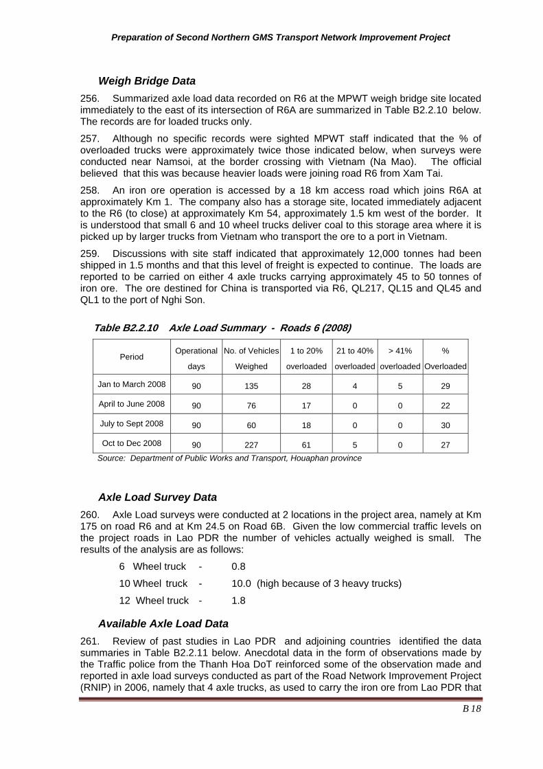
Preparation of Second Northern GMS Transport Network Improvement Project
B 18
Weigh Bridge Data 256. Summarized axle load data recorded on R6 at the MPWT weigh bridge site located immediately to the east of its intersection of R6A are summarized in Table B2.2.10 below. The records are for loaded trucks only.
257. Although no specific records were sighted MPWT staff indicated that the % of overloaded trucks were approximately twice those indicated below, when surveys were conducted near Namsoi, at the border crossing with Vietnam (Na Mao). The official believed that this was because heavier loads were joining road R6 from Xam Tai.
258. An iron ore operation is accessed by a 18 km access road which joins R6A at approximately Km 1. The company also has a storage site, located immediately adjacent to the R6 (to close) at approximately Km 54, approximately 1.5 km west of the border. It is understood that small 6 and 10 wheel trucks deliver coal to this storage area where it is picked up by larger trucks from Vietnam who transport the ore to a port in Vietnam.
259. Discussions with site staff indicated that approximately 12,000 tonnes had been shipped in 1.5 months and that this level of freight is expected to continue. The loads are reported to be carried on either 4 axle trucks carrying approximately 45 to 50 tonnes of iron ore. The ore destined for China is transported via R6, QL217, QL15 and QL45 and QL1 to the port of Nghi Son.
Table B2.2.10 Axle Load Summary - Roads 6 (2008)
Period Operational
days
No. of Vehicles
Weighed
1 to 20%
overloaded
21 to 40%
overloaded
> 41%
overloaded
%
Overloaded
Jan to March 2008 90 135 28 4 5 29
April to June 2008 90 76 17 0 0 22
July to Sept 2008 90 60 18 0 0 30
Oct to Dec 2008 90 227 61 5 0 27 Source: Department of Public Works and Transport, Houaphan province
Axle Load Survey Data 260. Axle Load surveys were conducted at 2 locations in the project area, namely at Km 175 on road R6 and at Km 24.5 on Road 6B. Given the low commercial traffic levels on the project roads in Lao PDR the number of vehicles actually weighed is small. The results of the analysis are as follows:
6 Wheel truck - 0.8
10 Wheel truck - 10.0 (high because of 3 heavy trucks)
12 Wheel truck - 1.8
Available Axle Load Data 261. Review of past studies in Lao PDR and adjoining countries identified the data summaries in Table B2.2.11 below. Anecdotal data in the form of observations made by the Traffic police from the Thanh Hoa DoT reinforced some of the observation made and reported in axle load surveys conducted as part of the Road Network Improvement Project (RNIP) in 2006, namely that 4 axle trucks, as used to carry the iron ore from Lao PDR that

Preparation of Second Northern GMS Transport Network Improvement Project
B 19
the trucks were as heavy as 70 tonnes (on 4 axles - 2 x 2 wheel axles and 2 x 4 wheel axles). Trucks carrying cement, timber and other similar materials also heavily loaded.
262. A summary of the damage factors adopted for the commercial traffic is presented in Table B2.2.11 below. The calculations reflect the fact that most trucks are only loaded for approximately 60% of the time. When empty even heavy trucks only cause less than 10% of the damage when they are loaded. The adopted figures have taken into account that the trucks carrying materials (cement/timber) are from Vietnam. The measured loads varied greatly, while most loaded trucks were at or below slightly higher than the legal limit, a few truck, 4 in the 30 vehicles surveyed were, up to twice the legal limit. The adopted DF for the 10 and 12 wheel vehicles therefore reflect this by being more than double the DF for a legally loaded truck.
Table B2.2.11 - Damaging Factors (ESAL by Vehicle Type)
Vehicle Type Lao Data Vietnam
(RNIP 2006) on Major National Highways
Adopted for Use in Design of Project
Roads
Small Bus _ _ 0.4
Bus 1.5 1.5 1.5
Small truck 0.2 _ 0.2
6 wheel Truck 0.8 1.5 1.1
10 wheel Truck** 0.8 to 10 4 4.1
12 Wheel Truck ** 1.8 to 28 7 - 12 9.1
12 Wheel Cement and Material Trucks 24 26 24
12 Wheel Iron Ore Truck (or similar) 89.0 ND 89
Source: RNIP, MoT ,Project and Axle load surveys
Notes: ** Range reflects the fact that trucks loads vary form legal loads through to extreme overloading (40 to 79 tons on 3 and 4 axle trucks).
B2.2.10 Rural Roads 263. The project screened 370 km of roads using data available for the road asset management system used by the MPWT for their road and maintenance programs. This was supplemented by the collection of more recent data for the 2 key districts, namely Vieng xay and Sop Bao, where most of the likely candidate roads were located. The resulting short list of roads, with a length of 150 km is presented in Table B2.2.12 below. This list will be reduced to approximately 100 km after the next phase which will include details assessment of each road to determine work needs and identify social. Resettlement and environmental impacts.
264. The screening process was based on the quality of present road accessibility and the percentage of poor people being served by road. While most of the roads connect directly to the road sections to be upgraded a number connect to the road corridor. Full details of the screening process are included in Annex D of Part B.

Preparation of Second Northern GMS Transport Network Improvement Project
B 20
Table B2.2.12 Rural Roads Short List
Ranking Road District Start End Length (km) Comment
1 3238 Viengxay B. Longkhou B. Phonthong 15.00
2 3239 Viengxay B. Phounmay B. Naheua 9.00
The road serves villages, some of which are in
a protected forest area.
3 3581 Xiengkhor B. Nathong B. Nadeua 5.00
4 3415 Xamneua Jct Rd No.6 B. Ham Bornamoun 2.80
5 3475 Viengxay B. Khangkhong V/N Border 14.00
6 3483 Viengxay B. Meuangpou B. Pok 12.40
7 3223 Sopbao B.Nathene B Chakienne 7.00
8 3506 Huameuang B. Meuangpen B. Nampong 3.00
9 3244 Huameuang Jct Rd N.6 B. Vek
Jct Rd N.6 B. Phanang 15.60
10 3205 Xamneua B. Nasala B. Songkhao 35.00
11 3243 Huameuang Jct Rd No.6 B. Natok B. Pakhatay 23.0
12 3255 Sopbao B. Meuanghom B. Danhung
10.5

Preparation of Second Northern GMS Transport Network Improvement Project
B 21
B3.0 Road Alignment
B3.1 General 265. The proposed standards are Class 5, according to the current Lao Road Design Manual and Class 4 according to the revised manual which is yet to be approved. Details of the existing road standards are shown in Figure B3.1 Basic Road Cross Section, below.
B3.2 Road alignment geometry
B3.2.1 Horizontal alignment considerations
General 266. The project roads passes through a mixture of flat and hilly terrain, mostly the latter except on road R6A where the road is adjacent to Nam Ma.
267. The existing horizontal alignment of the project road in hilly to mountainous terrain is generally of a moderate standard for hilly terrain with average speeds of 45 to 60 kph, and maximum speeds approaching 80 kph on some straight sections. As indicated in sections above the alignment improvements possible in the more difficult terrain, are limited to small improvements in curve radius (horizontal and vertical), curve widening, passing lanes were grades are long and escape lanes where grades are steep and long.
268. It was noted during the inspections that while light vehicles and unloaded vans were often travelling at average speeds of 40 to 50 kph and higher in some sections, trucks were typically travelling at speeds of less than 20 kph and as low as 10 kph in the hilly and mountainous terrain. This applied whether the trucks travelled up or down the grade.
Road Alignment Improvements 269. It is expected that in addition to the horizontal alignment improvements listed in the Bidding Documents included in Supplementary Appendix Volume 8 it will be necessary to smooth out smaller horizontal. As these changes are small and cannot be specifically identified. The potential cost of the earthworks cost required for the smoothing has however been factored into the cost estimates.
270. Of the curves listed in Supplementary Appendix Volume 11, only a small percentage were found to be suitable for improvement (increased radius). The criteria used to identify the potential for improvement consisted of the following:
• Distance between tangent points of adjacent curves (there is a minimum distance required to allow the superelevation to develop from one direction to another between curves);
• Vertical grade (steep grades had a bigger impact on speed than curve radius); and
• Will improvement in curve radius require the construction of a fill (curves that cross drainage lines were observed to have very steep natural surface grades at the drainage lines, making it difficult to construct large fills with extensive retaining walls). This questions was assessed, initially from condition data and also from field observations.

Preparation of Second Northern GMS Transport Network Improvement Project
B 22
B3.2.2 Vertical alignment considerations
General 271. Topography, design speeds, grades, irrigation system requirements, areas of flooding and saturated areas need to be considered as should stopping sight distances. The existing vertical alignment is difficult wherever hilly or mountainous terrain is encountered especially east of Km 107, as summarized in Table B2.2.1.
272. It will be necessary and possible to improve some vertical curves to improve sight distance and to smooth vertical alignment and road shape deficiencies, As these changes are small and cannot be specifically identified the locations are not identified. The costs of this work is however factored into the cost estimate.
273. Specific issues are discussed below.
Raising of Embankment at Flood Prone and Wet Areas 274. Some parts of project road are flooded during rainy season and are subject to saturation during the rice growing areas (areas where rice fields are higher than the road). The identified road sections are summarized in Table B2.2.2 and B2.2.34 above.
Proposed Road Safety Road Features 275. Road safety should be considered in a comprehensive way through all aspects in the design of highways. The safety features that were used in the project road are as follows:
• Provision of a wider (1.5 to 2 metres depending on proposed road standard) sealed shoulder in areas of intensive usage by pedestrians and the slower no-motorized vehicles;
• Provision of improved sight distances;
• Improved horizontal geometry by providing curve widening at on all curves;
• Escape ramps on long and steep grades, if a suitable site can be identified;
• Climbing/passing lanes, where these can be provided;
• Road signs such as warning, information and direction signs, especially at curves less than 50 kph;
• Raised pavement reflectors on small radius curves;
• Lane Markings consist of centerline, edge line and pedestrian crossing;
• Speed humps and/or rumble strip at the entrance of populated town area and through the towns;
• Chicanes, physical traffic islands constructed on the shoulders to reduce speeds to the desired level, where the road passes through communities;
• Traffic islands at key intersection; and
• Guardrails provided on bridge approaches, box culverts and area where sharp curves, moderate to steep grades and high embankments are coincident.

Preparation of Second Northern GMS Transport Network Improvement Project
B 23
Road Sign and Marking 276. Road signs used in the project roads are classified into three types such as (i) regulatory signs, (ii) warning signs, and (iii) guide signs.
• Regulatory signs give drivers notice of traffic laws and regulations.
• Warning signs direct attention to condition of the road on or adjacent to a street that are potentially hazardous to traffic operation.
• Guide signs indicate route designations, directions/distances, points of interest, and other geographic or cultural information.
• Road markings placed on the pavement, curb, or object to convey traffic regulation and warnings to drivers. The types of road markings used for this project are (i) road centerlines, (ii) pavement edge markings to delineate separation of motor and bike traffic, and (iii) pedestrian crossings.
B3.3 Proposed Road Cross Section Details
B3.3.1 Proposed Upgrading of Lao PDR Roads (R6, R6A and R6B) 277. The road sections in Lao PDR carry less traffic and the task is a combination of upgrading and road reconstruction as some road sections have deteriorated to the point where they are gravel roads and others are deteriorating rapidly. Given the low traffic flows the proposed road standard for the three road sections to be upgraded is Class 4. However modified Class 5 may be found to be more appropriate on some road sections.
278. The road width standards for the project road, for the different section types corresponding to Class 4 are presented below.
Rural Section with Raised Embankment – The embankment formation width of 6.5m, consisting of 2 x 2.75m wide lanes equal to 5.5m carriageway, and 2 X 0.50m sealed shoulders. The road surface level will be raised to about 1.0m above the natural surface in flat terrain to minimize effects of localized flooding and saturation of the subgrade. Actual embankment height will variable depend on the reported flood water level alongside the road.
Rural Section - The width formation is 6.50m, consisting of 2 x 2.75m wide lanes equal to 5.5m carriageway, and 2 X 0.50m sealed shoulders.
Mountainous Section - The embankment width formation of 6.5m, consisting of 2 x 2.75m wide lanes equal to 5.50m carriageway, and 2 x 0.50m sealed shoulders.
Built-up or Sub-Urban Sections - The embankment width formation is 9.50m, consisting of 2 x 2.75m wide lanes equal to 5.5m carriageway, 2 x 2.00m sealed shoulders. (if there are curbs or lined drains along the road the unsealed portion would also be sealed).
Note:
a. The cross fall of road surface will be 3 % to ensure good surface drainage;
b. There will also be widening of the paved surface by up to 5 metres on very tight curves, but typically less than 3 metres;
c. Sub-base and base pavement layers would be constructed full width (no separate shoulder material); and
d. Shoulder would be sealed for whole their width to minimize wetting up of the sub-grade in the outer wheel path.

Preparation of Second Northern GMS Transport Network Improvement Project
B 24
B3.3.2 Proposed Alignment Improvements of Lao Roads (R6 and RC1) 279. Travel speeds along road R6 are generally in excess of 30 kph for a light vehicle (by observation) which would suggest that the horizontal alignment is generally acceptable. Where speeds are close to 30 kph or less, a steep grade and/or poor sight distance combined with a narrow pavement caused the driver to slow down.
280. Some 40 curves were identified for more detailed assessment, which will take place in May 2009. Preliminary observations suggest that the required road works will be small scale and will mostly be limited to making small increases to curve radii, pavement widening, shoulder sealing and improvements in sight distance.
281. Possible improvements in road alignment or road characteristics will include the following:
i) Small improvement in curve radius - by cutting into the hill or by filling across drainage lines. The latter option is only possible where the drainage lines is flat enough to construct a fill;
ii) Widening on curves - this is required, especially on the tight curves to allow vehicles to pass safely. The widening could be as much as 8 metres on the tight hairpin curves;
iii) Constructing passing bays and truck stops - on steep and long grades; and
iv) Constructing escape safety ramps - that could be used by drivers who lose control of their trucks, because of brake failure. To be constructed at suitable locations.
282. Although Road RC1 has not yet been inspected it is expected that the situation there will be similar to that on R6.
B3.3.3 Curve Widening 283. Curve widening should be applied to all curves in accordance with Table B3.3.1 below is an extract from this standard. Project proposed variations are also identified.
Table B3.3.1 Proposed curve widening (m)
Curve Radius <25m 25 to 50m 50 to 100m 100 to 150m >150m
Road Design Guide Not specified 2 1.5 0.9 0.2 to 0.7
Proposed by Project 2.9 2.5 2 0.9 0.2 to 0.7
B3.3.4 Superelevation 284. Superelevation should be considered horizontal alignment, climate, constructability adjacent land use and the frequency of slow-moving. Table B3.3.2 below is showing an extract from this standard. Project proposed variations are also identified.
285. The minimum value of superelevation is proposed 3.0 % which is considered cross-slope rate.

Preparation of Second Northern GMS Transport Network Improvement Project
B 25
Table B3.3.2 Proposed Superelevation (%)
Design Speed Curve Radius / Superelevation
180 m 190 m 200 m 210 m 70 kph
6.0 % 5.0 % 4.0 % 3.0 %
80 m 90 m 100 m 110 m 50 kph
8.0 % 6.0 % 4.0 % 3.0 %
60 m 65 m 70 m 80 m 40 kph
6.0 % 4.4 % 4.0 % 3.0 %
15 m 20 m 20 kph
5.5 % 3.0 %
Figure B3.1 - Basic Road Cross Section - Lao PDR Class 4 (modified)
Note: Formation width is 6.5 meters consisting of 2 traffic lanes of 2.75 meters and shoulders of 0.5 meter each side.
Subbase Base
0.5 m
DBST
2.75m 2.75m 0.5 m
6.5 m

Preparation of Second Northern GMS Transport Network Improvement Project
B 26
B4.0 DRAINAGE STRUCTURES AND WEIGHBRIDGE
B4.1 General 286. Four options have been envisaged, new construction, extension of existing structure, replacement and use without improvement in consideration of the following criteria.
• New Installation at realignment section and raised embankment sections;
• Extension of existing culverts where the existing condition is good and location and invert elevation are adequate, but narrower than the planned road width;
• Replacement where location, size, and/or discharge are not adequate or existing structure are damaged, have settled or a filled with sediment; and
• Use of Existing Structure where the location, size, width, status, etc of the existing drainage structures are adequate, these structures will be used as they are.
B4.2 Pipe and Box/Slab Culverts 287. The pipe and box culvert requirements, by road section are shown in Tables B4.2.1 and B4.2.2 respectively. Full details are presented in Appendix Volume 11 Drawings
Table B4.2.1 Summary of Pipe Culverts Requirements
Description R6 (Km 119 to 175) R6B R6A
Extend 186 No. 719m 19 No. 76m Refer to Drawings
Replace 89 No. 931m 40 No. 481m Refer to Drawings
New Construction 0 0 Refer to Drawings
Total Number 275 59 Refer to Drawings
Table B4.2.2 Summary of Box /Slab Culvert Requirements
Description R6 (Km 119 to 175) R6B R6A
Extend 20 No. 80m 1 No. 3 Refer to Drawings
Replace 0 0 Refer to Drawings
New Construction 0 0 Refer to Drawings
Total 20 1 Refer to Drawings
Preparation of Second Northern GMS Transport Network Improvement Project
B 27
B4.3 Weighbridge 288. It is proposed that an axle load facility is established at approximately Km 155 at the site that has already been identified and for which land has been acquired and the weigh equipment has been purchased as part of RMP2. This would replace the temporary site presently located at Km 111 on road R6. A second should be located on road R6A, immediately south of Sop Bao . This second site should be semi permanent facility initially. In both instances the site works would consist of the following:
• Construction of a weight scale area and building, including a parking area for overloaded trucks, at both sites;
• Construction of approach and departure lanes, back to the highway;
• Weigh scale equipment (Static) with connections to power and communications and buildings at approximately Km 155. Concrete pad for temporary scales at Bop Bao; and
• Establishment of the required systems and operating procedures and guideline for the operation of the facility and the training of staff.

Preparation of Second Northern GMS Transport Network Improvement Project
B 28
B5.0 Pavement Design
B5.1 General 289. The pavement design has been completed based on existing data, observations, surveyed and investigations. The results of pavement analysis and some results are included in Annex C, when the design has been completed.
290. The results of this analysis are presented in the tables below. Table B5.1.1 summarizes the road standard and design traffic load (ESAL) for each of the main road sections. This is based on the traffic and axle load analysis presented in section 2 above. Table B5.1.2 shows the thickness of pavement layers.
B5.2 Key Assumptions 291. Key Assumptions include the following:
a) It has been assumed that traffic will follow the same wheel path 75% of the time. The reasons for this include:
· The cross fall of 3% will tend to force traffic to straddle the centerline:
· The presence of pedestrians, bicycles, pedestrians on the shoulders;
· Use of shoulders and a part of the traffic lanes to dry agricultural produce;
· Narrow lane widths.
b) That conventional crushed/screened pavement materials would be used for base and subbase layer construction and a select subgrade (CBR of 8%) to minimize he cost of using more expensive subbase materials.
c) Possible of salvaging the existing pavement material was considered but was not assumed. There will need to be significant vertical alignment smoothing which means cutting into the existing pavement in one area and filling over the pavement in other areas It is possible that while desirable it my not be economic to salvage the existing pavement.
d) Stabilizing the existing subgrade is a possibility (but was assumed) that should be considered as it would reduce costs. Use depends on the type of contractors likely to be engaged to do the work and on a more detailed analysis of available materials.
e) Low traffic speeds of around 15 kph was assumed for the mountains and 40kph for the flat terrain. This means lower layer equivalence for the asphalt concrete layers
f) Above average temperatures were assumed . Main impact was on Asphalt concrete layer equivalence (it was lowered).

Preparation of Second Northern GMS Transport Network Improvement Project
B 29
Table B5.1.1 - Project Road Standards and Traffic Load - Lao PDR
Road Number Road Section/ Length
Proposed Standard
Seal/ Pavement Width
Design ESAL (million)
R6 56.0 Lao Cl. 4 (modified)
6/6.5 5
R6A 0 to 1.2 Lao Cl. 4 (modified)
6/6.5 3.5
R6A 1.2 to 62.4 Lao Cl. 4 (modified)
6/6.5 2.1
R6B 24.9 Lao Cl. 4 (modified)
6/6.5 1.9
R6 and R1D Spot improvements over 206 km
Improvements to curve radius
and width (select
l i )
Equal or wider than existing
1.0 Estimated from past traffic data
Source: Consultant
Table B5.1.2 - Lao PDR Project Road Pavement Thickness Designs (Preliminary)
Road Section Comment Surfacing Aggregate Base
Granular Subbase
(Select) Subgrade
R 6 - Km 119 to 175
Road reconstruction DBST 200
325 0 (300)
R6A - Km 0 to 1.2 Road reconstruction DBST 200 375 0
R6A - Km 1.2 to 62.4
Road reconstruction DBST 200 350 0
R6B 24.9 Road reconstruction DBST 200 300 0 (300)
R6 – km 0 to 119 R1C - Km 0 to 93.2
Curve and width improvements DBST 200
200 0
Rural Roads Reconstruction To be advised
To be advised
To be advised
To be advised
Source: Consultant Note: Some sections have a soft clay with CBR of 2%. The select subgrade (in brackets)will be required in these sections

Preparation of Second Northern GMS Transport Network Improvement Project
B 30
B6.0 Cost Estimates
B6.1 General 292. Cost estimate has been prepared to obtain the project quantities for civil works and project cost for economic evaluation. Details of the estimate are discussed below.
293. The unit rates were estimated as of 2009, and compared with latest contracts in Lao PDR, and then adjusted to reflect expected costs in 2012. As the inflation rate has been 10% for 2009 – 2010 years and this is expected
B6.2 Assumption made in the Cost Estimates 294. Cost estimates have been made in accordance with the following criteria:
· It is assumed that international contractor awarded through ADB international competitive bidding procedure will undertake the civil works;
· The contractor will be allow to import free of duties for equipment provided that those equipment is re-exported upon completion of the works.
· The contractor will be allowed to bring his managerial personnel, engineers and skilled laborers required for the project into Cambodia; and
· The unit price of each bill item were estimated as of 2012.
295. Cost estimate details can be seen in Supplementary Appendix Volume 11. A summary of costs per kilometer are shown in Table 6.4.2 below.
B6.3 Construction unit rates 296. The key unit rates are shown in Table B6.3.1 below. More detailed list of unit rates are shown in Table B6.4.2 – B6.4.4 Civil work cost of project roads (R6, R6A and R6B).
Table B6.3.1 Unit Rates for Major Items
No. Description Unit Rate Remarks
1 Roadway Excavation Cu.m 1.60
2 Embankment Cu.m 2.70
3 Base Course Cu.m 20.50
4 Subbase Course Cu.m 18.00
6 Prime Coat Litter 0.99
7 Seal Coat Litter 0.75
8 Cover Material(16 mm nominal size)
Cu.m 30.00
9 Cover Material(10 mm nominal size)
Cu.m 33.00
10 Bridge substructure concreteGrade 30
Cu.m 233.56

Preparation of Second Northern GMS Transport Network Improvement Project
B 31
B6.4 Proposed Construction Contracts 297. Construction contracts of project roads including bridges are proposed as detailed in Table A6.4.1 below.
Table B6.4.1 Construction Cost
2012 US$ Road Number
Length (km)
2009 Net (US$) Net US$ Contingency Contingency Total
R6 55.00 14,513,990 15,965,389 1,596,539 1,756,193 19,318,120
R6A 62.40 12,167,211 13,383,932 1,338,393 1,472,233 16,194,558
R6B 24.90 6,362,428 6,998,671 699,867 769,854 8,468,391
Total 143.30 33,043,629 36,347,992 3,634,799 3,998,279 43,981,070
R6 and R1C 212.00 6,487,811 7,136,593 713,659 785,025 8,635,277
Rural Roads 122.20 4,346,340 4,780,974 478,097 525,907 5,784,978
Total 10,834,151 11,917,567 1,191,756 1,310,932 14,420,255
Grand Total
43,877,780 48,265,559 4,826,555 5,309,211 58,401,325
Source: Consultant
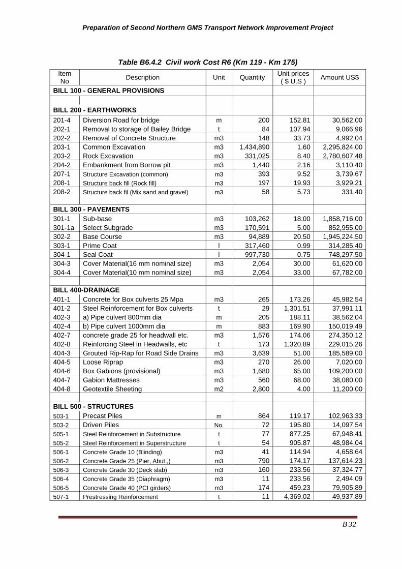
Preparation of Second Northern GMS Transport Network Improvement Project
B 32
Table B6.4.2 Civil work Cost R6 (Km 119 - Km 175) Item No Description Unit Quantity Unit prices
( $ U.S ) Amount US$
BILL 100 - GENERAL PROVISIONS
BILL 200 - EARTHWORKS
201-4 Diversion Road for bridge m 200 152.81 30,562.00202-1 Removal to storage of Bailey Bridge t 84 107.94 9,066.96202-2 Removal of Concrete Structure m3 148 33.73 4,992.04203-1 Common Excavation m3 1,434,890 1.60 2,295,824.00203-2 Rock Excavation m3 331,025 8.40 2,780,607.48204-2 Embankment from Borrow pit m3 1,440 2.16 3,110.40207-1 Structure Excavation (common) m3 393 9.52 3,739.67208-1 Structure back fill (Rock fill) m3 197 19.93 3,929.21208-2 Structure back fil (Mix sand and gravel) m3 58 5.73 331.40
BILL 300 - PAVEMENTS
301-1 Sub-base m3 103,262 18.00 1,858,716.00301-1a Select Subgrade m3 170,591 5.00 852,955.00302-2 Base Course m3 94,889 20.50 1,945,224.50303-1 Prime Coat l 317,460 0.99 314,285.40304-1 Seal Coat l 997,730 0.75 748,297.50304-3 Cover Material(16 mm nominal size) m3 2,054 30.00 61,620.00304-4 Cover Material(10 mm nominal size) m3 2,054 33.00 67,782.00
BILL 400-DRAINAGE
401-1 Concrete for Box culverts 25 Mpa m3 265 173.26 45,982.54401-2 Steel Reinforcement for Box culverts t 29 1,301.51 37,991.11402-3 a) Pipe culvert 800mm dia m 205 188.11 38,562.04402-4 b) Pipe culvert 1000mm dia m 883 169.90 150,019.49402-7 concrete grade 25 for headwall etc. m3 1,576 174.06 274,350.12402-8 Reinforcing Steel in Headwalls, etc t 173 1,320.89 229,015.26404-3 Grouted Rip-Rap for Road Side Drains m3 3,639 51.00 185,589.00404-5 Loose Riprap m3 270 26.00 7,020.00404-6 Box Gabions (provisional) m3 1,680 65.00 109,200.00404-7 Gabion Mattresses m3 560 68.00 38,080.00404-8 Geotextile Sheeting m2 2,800 4.00 11,200.00
BILL 500 - STRUCTURES
503-1 Precast Piles m 864 119.17 102,963.33503-2 Driven Piles No. 72 195.80 14,097.54505-1 Steel Reinforcement in Substructure t 77 877.25 67,948.41505-2 Steel Reinforcement in Superstructure t 54 905.87 48,984.04506-1 Concrete Grade 10 (Blinding) m3 41 114.94 4,658.64506-2 Concrete Grade 25 (Pier, Abut.,) m3 790 174.17 137,614.23506-3 Concrete Grade 30 (Deck slab) m3 160 233.56 37,324.77506-4 Concrete Grade 35 (Diaphragm) m3 11 233.56 2,494.09506-5 Concrete Grade 40 (PCI girders) m3 174 459.23 79,905.89507-1 Prestressing Reinforcement t 11 4,369.02 49,937.89

Second Northern GMS Transport Network Improvement Project (TA 6478-REG)
B 33
Item No Description Unit Quantity Unit prices
( $ U.S ) Amount US$
507-2-3 Launching Girder 25m span Unit 6 1,157.00 6,941.97507-2-5 Launching Girder 33m span Unit 5 1,601.99 8,009.97508-1 Bridge Bearings No. 22 320.84 7,058.56508-2 Expansion joint m 28 170.51 4,774.15
BILL 600 - MISCELLANEOUS
601-1 Box gabion (1x1x2m) m3 245 40.87 10,021.81601-2 Reno matress (0.3x1x2m) m3 248 39.44 9,776.75601-3 Geotextile m2 1,239 2.90 3,594.15602-2 Grouted Rip-Rap for slope protection m3 85 60.00 5,128.20603-1 Provide and fix guard rails m 160 40.05 6,407.97604-1 Road markings m2 750 11.75 8,812.50605-1 Traffic signs single post No. 8 81.53 652.26605-2 Traffic signs double post No. 4 102.43 409.72606-1 Provide and fix kilometer post No. 25 50.00 1,250.00606-2 Provide and fix edge marker post No. 250 19.00 4,750.00
Total 12,731,569.98:General Provisions 14% 1,782,419.80
Sub Total (2009) 14,513,989.78
2009-2010 2010-2011 2011-2012
Sub Total (2012) considered annual escalation 10% 0% 0% 15,965,388.76
Contingencies 10% 1,596,538.88
Tax 10% 1,756,192.76
Grand Total 19,318,120.40

Second Northern GMS Transport Network Improvement Project (TA 6478-REG)
B 34
Table B6.4.3 Table B6.4.2 Civil work Cost Bill of Quantities Contract R6A Item No Description Unit Quantity Unit prices
( $ U.S ) Amount ( $ U.S )
BILL 100 - GENERAL PROVISIONS
BILL 200 - EARTHWORKS
201-1 Clearing and grubbing,150mm of top soil m2 85,400 0.35 29,890.00 201-4 Diversion Road for bridge m 400 152.81 61,124.96 202-1 Removal to storage of Bailey Bridge t 100 79.00 7,900.00 202-2 Removal of Concrete Structure m3 282 33.70 9,503.40
202-3 Demolish and remove brickwork/stonework m3 868 8.90 7,725.17
202-4 Removal of concrete/steel pipe m 572 11.00 6,292.00 203-1 Common Excavation m3 760,000 1.60 1,216,000.00 203-2 Rock Excavation m3 25,000 8.40 210,000.00 203-3 Disposal of Unsuitable Material m3 2,100 4.50 9,450.00 204-1 Embankment from Excavation m3 63,700 2.70 171,990.00 204-2 Embankment from Borrow pit m3 2,880 3.90 11,232.00 207-1 Structure excavation (common) m3 1,080 9.50 10,257.15 207-2 Structure excavation (Rock) m3 962 14.70 14,141.40 208-1 Structure back fill (Rock fill) m3 394 19.93 7,858.38 208-2 Structure back fil (Mix sand and gravel) m3 116 5.73 662.82
BILL 300 - PAVEMENTS
301-1 Sub-base m3 109,452 18.00 1,970,136.00 302-2 Base Course m3 107,973 20.50 2,213,446.50 303-1 Prime Coat l 336,490 0.99 333,125.10 304-1 Seal Coat l 1,057,541 0.75 793,155.75 304-3 Cover Material(16 mm nominal size) m3 2,177 30.00 65,310.00 304-4 Cover Material(10 mm nominal size) m3 2,177 33.00 71,841.00
BILL 400-DRAINAGE
401-1 Concrete for Box culverts 25 Mpa m3 1,380 173.26 239,095.35 401-2 Steel Reinforcement for Box culverts t 92 1,301.51 119,739.04 402-3 a) Pipe culvert 800mm dia m 910 188.11 171,177.83 402-4 b) Pipe culvert 1000mm dia m 124 169.90 21,067.29 402-5 c) Pipe culvert 1200mm dia m 13 325.00 4,225.00 404-3 Grouted Rip-Rap for Road Side Drains m3 17,275 51.00 881,025.00 404-4 Stone Masonry m3 1,690 52.00 87,880.00
BILL 500 - STRUCTURES
503-1 Precast Piles m 864 119.17 102,963.33 503-2 Driven Piles No. 72 195.80 14,097.54 505-1 Steel Reinforcement in Substructure t 160 877.25 140,414.66 505-2 Steel Reinforcement in Superstructure t 86 905.87 78,242.71 506-1 Concrete Grade 10 (Blinding) m3 56 114.94 6,442.44 506-2 Concrete Grade 25 (Pier, Abut.,) m3 1,636 174.17 284,877.26 506-3 Concrete Grade 30 (Deck slab) m3 296 233.56 69,184.86 506-4 Concrete Grade 35 (Diaphragm) m3 21 233.56 4,869.41 506-5 Concrete Grade 40 (PCI girders) m3 257 459.23 118,021.92 507-1 Prestressing Reinforcement t 15 4,369.02 64,836.25
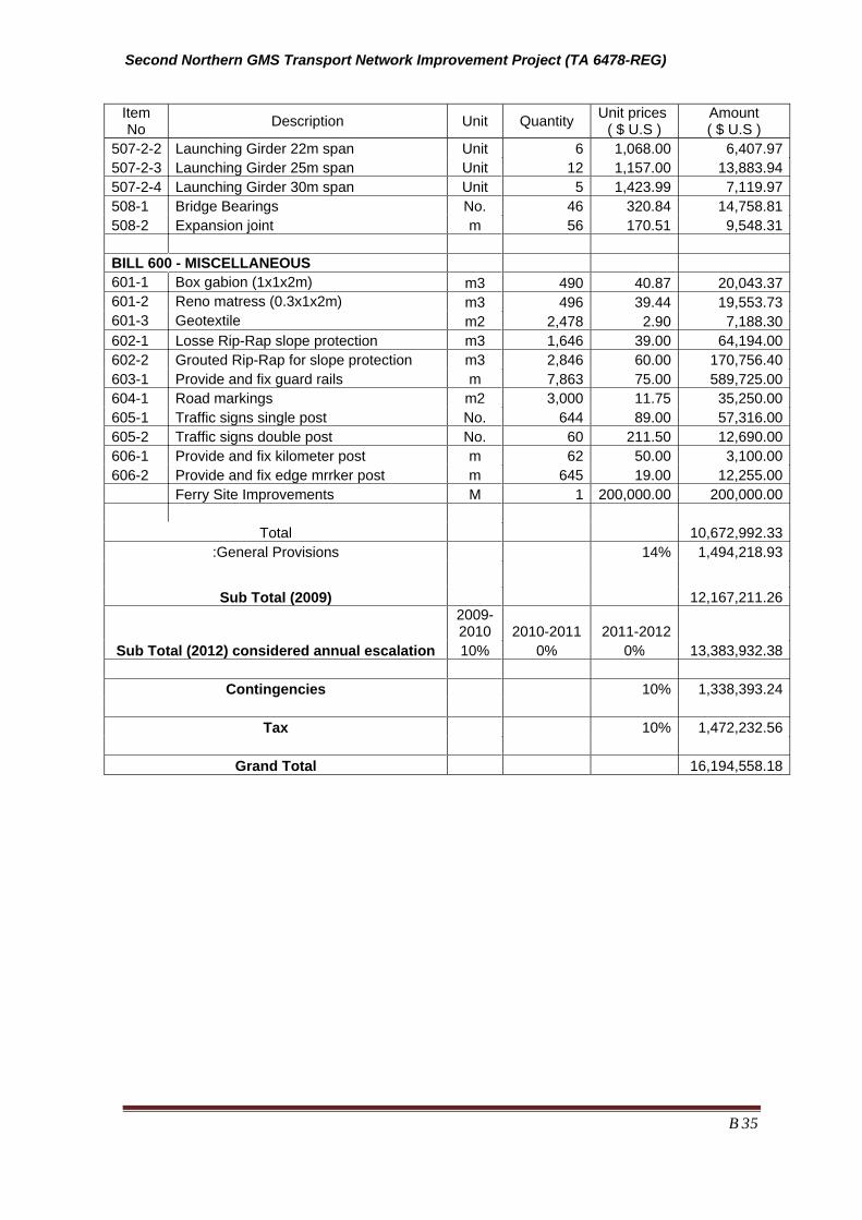
Second Northern GMS Transport Network Improvement Project (TA 6478-REG)
B 35
Item No Description Unit Quantity Unit prices
( $ U.S ) Amount ( $ U.S )
507-2-2 Launching Girder 22m span Unit 6 1,068.00 6,407.97 507-2-3 Launching Girder 25m span Unit 12 1,157.00 13,883.94 507-2-4 Launching Girder 30m span Unit 5 1,423.99 7,119.97 508-1 Bridge Bearings No. 46 320.84 14,758.81 508-2 Expansion joint m 56 170.51 9,548.31
BILL 600 - MISCELLANEOUS
601-1 Box gabion (1x1x2m) m3 490 40.87 20,043.37 601-2 Reno matress (0.3x1x2m) m3 496 39.44 19,553.73 601-3 Geotextile m2 2,478 2.90 7,188.30 602-1 Losse Rip-Rap slope protection m3 1,646 39.00 64,194.00 602-2 Grouted Rip-Rap for slope protection m3 2,846 60.00 170,756.40 603-1 Provide and fix guard rails m 7,863 75.00 589,725.00 604-1 Road markings m2 3,000 11.75 35,250.00 605-1 Traffic signs single post No. 644 89.00 57,316.00 605-2 Traffic signs double post No. 60 211.50 12,690.00 606-1 Provide and fix kilometer post m 62 50.00 3,100.00 606-2 Provide and fix edge mrrker post m 645 19.00 12,255.00 Ferry Site Improvements M 1 200,000.00 200,000.00
Total 10,672,992.33 :General Provisions 14% 1,494,218.93
Sub Total (2009) 12,167,211.26
2009-2010 2010-2011 2011-2012
Sub Total (2012) considered annual escalation 10% 0% 0% 13,383,932.38
Contingencies 10% 1,338,393.24
Tax 10% 1,472,232.56
Grand Total 16,194,558.18
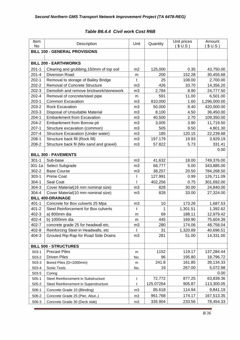
Second Northern GMS Transport Network Improvement Project (TA 6478-REG)
B 36
Table B6.4.4 Civil work Cost R6B Item No Description Unit Quantity Unit prices
( $ U.S ) Amount ( $ U.S )
BILL 100 - GENERAL PROVISIONS
BILL 200 - EARTHWORKS 201-1 Clearing and grubbing,150mm of top soil m2 125,000 0.35 43,750.00 201-4 Diversion Road m 200 152.28 30,455.68 202-1 Removal to storage of Bailey Bridge t 25 108.00 2,700.00 202-2 Removal of Concrete Structure m3 426 33.70 14,356.20 202-3 Demolish and remove brickwork/stonework m3 2,784 8.90 24,777.50 202-4 Removal of concrete/steel pipe m 591 11.00 6,501.00 203-1 Common Excavation m3 810,000 1.60 1,296,000.00 203-2 Rock Excavation m3 50,000 8.40 420,000.00 203-3 Disposal of Unsuitable Material m3 8,100 4.50 36,450.00 204-1 Embankment from Excavation m3 40,500 2.70 109,350.00 204-2 Embankment from Borrow pit m3 3,005 3.90 11,719.50 207-1 Structure excavation (common) m3 505 9.50 4,801.30 207-4 Structure Excavation (Under water) m3 185 120.15 22,239.68 208-1 Structure back fill (Rock fill) m3 197.179 19.93 3,929.19 208-2 Structure back fil (Mix sand and gravel) m3 57.822 5.73 331.41 0.00 BILL 300 - PAVEMENTS
301-1 Sub-base m3 41,632 18.00 749,376.00 301-1a Select Subgrade m3 68,777 5.00 343,885.00 302-2 Base Course m3 38,257 20.50 784,268.50 303-1 Prime Coat l 127,991 0.99 126,711.09 304-1 Seal Coat l 402,256 0.75 301,692.00 304-3 Cover Material(16 mm nominal size) m3 828 30.00 24,840.00 304-4 Cover Material(10 mm nominal size) m3 828 33.00 27,324.00 BILL 400-DRAINAGE
401-1 Concrete for Box culverts 25 Mpa m3 10 173.26 1,687.53 401-2 Steel Reinforcement for Box culverts t 1 1,301.51 1,392.62 402-3 a) 800mm dia m 69 188.11 12,979.42 402-4 b) 1000mm dia m 445 169.90 75,604.39 402-7 concrete grade 25 for headwall etc. m3 280 174.06 48,758.04 402-8 Reinforcing Steel in Headwalls, etc t 31 1,320.89 40,696.51 404-3 Grouted Rip-Rap for Road Side Drains m3 281 51.00 14,331.00
BILL 500 - STRUCTURES
503-1 Precast Piles m 1152 119.17 137,284.44 503-2 Driven Piles No. 96 195.80 18,796.72 503-3 Bored Piles (D=1000mm) m 241.8 161.85 39,134.33 503-4 Sonic Tests No. 19 267.00 5,072.98 503-5 Coring 0.00 505-1 Steel Reinforcement in Substructure t 72.772 877.25 63,839.36 505-2 Steel Reinforcement in Superstructure t 125.07264 905.87 113,300.05 506-1 Concrete Grade 10 (Blinding) m3 85.618 114.94 9,841.19 506-2 Concrete Grade 25 (Pier, Abut.,) m3 961.768 174.17 167,513.35 506-3 Concrete Grade 30 (Deck slab) m3 335.904 233.56 78,454.33

Second Northern GMS Transport Network Improvement Project (TA 6478-REG)
B 37
Item No Description Unit Quantity Unit prices
( $ U.S ) Amount ( $ U.S )
506-4 Concrete Grade 35 (Diaphragm) m3 10.0548 233.56 2,348.42 506-5 Concrete Grade 40 (PCI girders) m3 285.84 459.23 131,266.09 507-1 Prestressing Reinforcement t 19.37 4,369.02 84,627.90 306-1 Asphalt concrete for bridge m3 34.65 124.24 4,305.04
507-2-5 Launching Girder 33m span Unit 12 1,601.99 19,223.92 508-1 Bridge Bearings No. 48 320.84 15,400.50 508-2 Expansion joint m 56 170.51 9,548.31 509-1 Bridge Railling m 211.92 39.51 8,372.31 510-1 Water Proof m2 1143.1 6.23 7,121.48 510-2 Bridge Name Plaque No. 2 222.50 445.00 510-3 Drainage No. 30 8.90 267.00
BILL 600 - MISCELLANEOUS
601-1 Box gabion (1x1x2m) m3 245 40.87 11,260.36 601-2 Reno matress (0.3x1x2m) m3 248 39.44 10,985.29 601-3 Geotextile m2 1,239 2.90 4,038.39 602-2 Grouted Rip-Rap for slope protection m3 314 60.00 18,823.20 603-1 Provide and fix guard rails m 290 75.00 21,750.00 604-1 Road markings m2 750 11.75 8,812.50 605-1 Traffic signs single post No. 12 89.00 1,068.00 605-2 Traffic signs double post No. 6 211.50 1,269.00 606-1 Provide and fix kilometer post No. 25 50.00 1,250.00 606-2 Provide and fix edge marker post No. 250 19.00 4,750.00
Total 6,988,764.02
:General Provisions 14% 5,581,077.01
781,350.78
Sub Total (2009)
2009-2010 2010-2011 2011-2012 6,362,427.79
Sub Total (2012) considered annual escalation 10% 0% 0% 6,998,670.57
Contingencies 10% 699,867.06
Tax 10% 769,853.76
Grand Total

Second Northern GMS Transport Network Improvement Project (TA 6478-REG)
B 38
Annex A of Part B
Engineering Review of Road 6A Design
B/A 1. Introduction
298. The design was completed in 2008/09 with the assistance of the World Bank having originally being started in 2003. The road was designed to a Class 5 standard because the traffic levels were low and because available funding for upgrading was low. To keep within the budget the project bid document excluded bridges although the engineering investigations carried out some investigations and made recommendations on required bridges.
299. The contract documents are for the section relevant to the project are between Km 0 to 64 which includes some of the road section in Sop Bao which has recently been upgraded with the assistance of KfW. The documents would therefore need to be modified to reflect this change and also include the road to the existing ferry or .
300. The summary presented below is based primarily on design and bidding documents prepared by MPWT and consultants (Lao Transport Engineering Consultants and SD and XP Consultants Group) with the assistance of the World Bank. It is also based on visual inspections of the alignment and structures.
B/A2. Road Engineering
B/A 2.1 Road Description 301. Like most of the roads in this area the road is either located in a valley on the side of the valley where it closely follows the shape of the terrain. The road has a macadam pavement for the first 10 to 11 Km after which it is a gravel road. The first 10 km has a formation width that is close to that of the newly adopted standard which would suggest the construction costs could be low. Elsewhere the alignment is slightly less well defined with more undulations even where the road is located in river flood plains. The road in these latter locations is at time barely above the natural surface and therefore subjected to soaked conditions during the rice growing season.
B/A 2.2 Traffic levels 302. Traffic counts conducted for 24 hours per day over 7 days at 2 location in early to late August 2009 at Km 57, approximately 5 km south of Sop Bao. The count recorded 247 two and four wheeled vehicles, of which 219 were motorcycles, 15 were light vehicles and vans and 14 were trucks and buses. Another count conducted north of Sop Bao recorded 194 vehicles with a similar breakdown of vehicle types.
303. Traffic investigations and counts conducted during the ADB funded TA in April 2009 has found that the traffic levels are not only higher than previously reported but the growth rates are also high. Further mine traffic on the first 1 kilometer of road 6A not only add to the traffic levels but also add significantly to the traffic load on the pavements. The traffic count data, the growth rates and the projected future traffic on road R6A are summaries in Section B2.2.6 above.

Second Northern GMS Transport Network Improvement Project (TA 6478-REG)
B 39
304. The ESAL, for a design period of 20 years for sections KM 0 and 1.2 is 3.5 million while that between Km 1.2 and Km 62.5 is 2.1 billion respectively. This is based on a limited axle load survey completed during the study, axle load measurements from a axle load control site on road R6 and also data from Vietnam.
B/A 2.3 Alignment Issues 305. Apart form the need to improve curve radius and minimize grades, which will be difficult to achieve in many places the other key concerns include crossing low areas which are subject to saturation, ensuring that the irrigation system is preserved, improving alignments at new/replacement bridge locations, and ensuring good road drainage. As identified in the R6A bid documentation the road levels are also controlled by irrigation level requirements as many of the pipes carry irrigation water under the road.
B/A 2.4 Adopted Road Standards 306. The adopted road design standard is Lao Road Design Standard Class 4 (modified) which consists of a 6.5 meter sealed surface on a 6.5 meter road formation in rural road sections and wider section through villages. This would appear to be appropriate. Adopted road standards are sown in Table B/B 2 below.
307.
B/A 2.5 Design Alignment 308. There are no specific comments on the design itself.
B/A 2.6 Specification 309. The specification is based on the Lao MPWT Standard specification. Points of concern in the bid document specification and the standard document are listed below. They are of concern because the performance of pavement in Laos is below that which one would expect with many pavement starting to show serious signs of distress at around 8 years. Given the low traffic levels on many roads this is unexpected. While there are a number of possible reasons (poor quality control, overloading, etc) some that are often not discussed are listed below:
1 Use of high plasticity materials, especially in the subbase (TRL Road Note 31is often used for pavement thickness design in Laos but the documents recommendation that the Plasticity Index (PI) of subbase is less than 9% for wet climates is ignored). The MPWT specification of a PI 15%. The suggested maximum subbase PI has been adopted for ADB 11 and this practice should be adopted for ADB12 (Road R6A) ;
2 CBR requirements are specified for 4 days of soaking, yet this is not likely to reflect the moisture conditions of the subgrade for the more plastic soils. The specification in ADB 11 requires 10 days of soaking, which recognises the inadequacy of the standard 4 days of soaking. Although the requirement is positive it is conservative. It is recommended that the specification states that the minimum soaking period is 4 days and the longest is based on the change in sample swelling rate, in the CBR mould, which is normally recorded daily. When the swelling has stopped the sample should be removed from the water bath and prepared for the CBR test. Moisture content of the sample should be recorded of the sample immediately after the CBR test has been completed, as should the duration of soaking; and
3 Use of boxed pavement construction where the shoulders are constructed from a subgrade or subbase material. Neither material drains well which

Second Northern GMS Transport Network Improvement Project (TA 6478-REG)
B 40
means that water which enters the base around the seal edge or through cracks in the seal drains downwards and saturates the subgrade resulting in early failure. This needs to be corrected.
B/A2.7 Road pavement design
B/A2.7.1 General 310. The pavement design has been based on the assumption that suitable materials are available along the road. While this may be true for the crushed rock base it is not true for the subbase layer as none of the identified borrow areas indicated that a suitable source of subbase material was available. The unit rate used in the estimates indicate that the designers however expected to use a natural gravel rather than a crushed rock for the subbase.
311. The design assumes a crushed base thickness on 200 mm on a subbase of variable thickness. This is based on a CBR of 8% the adopted CBR for the select subgrade which is to be placed wherever the insitu material has a CBR of less than 8%. These CBRs are measured after 4 days of soaking which, as indicated above is likely to understate the actual insitu road conditions. Additional investigation tasks include the following:
• Additional testing is required with materials soaked until they stop swelling in the mould, with the minimum soaking period being 4 days before a subgrade design CBR is determined;
• A subbase with the required specification requirements needs to be identified and if not then a crushed rock subbase, or a modified subbase needs to be proposed and an appropriate unit cost used in the cost estimates;
• Pavement designs need to adopt the higher ESALs documented in this document. This will result in a change in quantities and costs;
• The increase in pavement thickness will mean that design levels will change, may mean that new drawings will need to be produced.;
• A new engineers estimate would need to be produced that reflects the thicker pavement and also a more expensive subbase material.

Second Northern GMS Transport Network Improvement Project (TA 6478-REG)
B 41
Annex B of Part B Proposed Road
Standards Lao PDR
Table B/B 1 Lao Road Standards
Item Class 4 Class 5
Traffic (AADT) 300 to 1,000 100 to 300
Terrain F R M F R M
Design speed (kph) 80 60 40 60 40 20
Formation width (m) 9 9 7 7 7 6.5
Number of lanes 2 2 2 2 2 2
Lane width (m) 3 3 3 2.75 2.75 2.5
Shoulder width (m) 1.5 1.5 0.5 0.75 0.75 0.5
Maximum gradient (%) 6 6 8 7 8 9
Minimum horizontal curve (m) 250 130 60 130 60 20
Crest - Safe sight distance (m)
Crest - Safe stopping distance
Crossfall (%) 3 3 3 3 3 3
Superelevation (%) (Side friction factor = 0.15)
3 - 10 3 - 10
Bridge Design Live Load HS25-44 HS20-44
Maximum axle load (tons) 9.1

Second Northern GMS Transport Network Improvement Project (TA 6478-REG)
B 42
Table B/B 2 Geometric Design Standard Adopted for Laos (Laos Class IV modified)
Road Name
R6
R1C
R6A
R6B
No. Main Parameter Unit Mountain Mountain
1. Design speed km/h 40 40
2. Number of lanes No. 2 2
3. Formation width M 7.0(6.5) 7.0(6.5)
4. Traffic lane width M 3.0(2.75) 3.0(2.75)
5. Outer shoulder width M 0.50 0.50
6. Inner shoulder width M - -
7. Maximum longitudinal gradient % 8(12) 8(12)
8. Median to be applied over 4-lane M - -
9. Minimum horizontal curvature M 60(30) 60(20)
10. Superelevation at minimum horizontal curvature % 6 6
11. Minimum radii of vertical curves: crest M - -
12. Minimum radii of vertical curves: sag M - -
13. Cross fall of carriageway % 3 3
14. Cross fall of shoulder % 3 3
15. Pavement structure
Surface
Base Course
Sub Base Course
Select Subgrade
DBST
20 cm
20 cm
*10-30 cm
DBST
20 cm
20 cm
*10-30 cm
M = meter, km/h = kilometer per hour, No. = number.
*Select subgrade: if subgrade CBR is less than 8 %, e.g. 6 % or 7 % to be 10 cm Select subgrade,
and 2 % or 3 % to be 30 cm Select subgrade.
Source: Ministry of Transport and Communication. ( ): absolute minimum/maximum considered economic
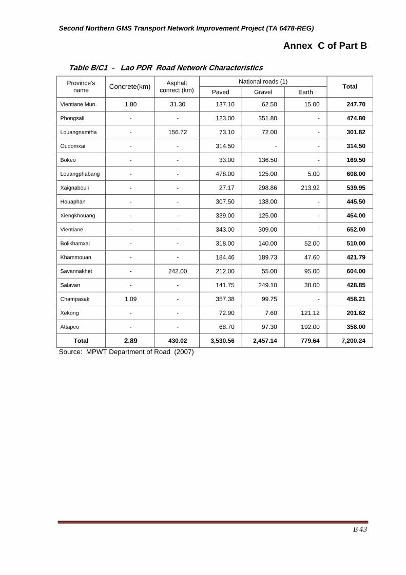
Second Northern GMS Transport Network Improvement Project (TA 6478-REG)
B 43
Annex C of Part B
Table B/C1 - Lao PDR Road Network Characteristics National roads (1) Province's
name Concrete(km) Asphalt conrect (km) Paved Gravel Earth
Total
Vientiane Mun. 1.80 31.30 137.10 62.50 15.00 247.70
Phongsali - - 123.00 351.80 - 474.80
Louangnamtha - 156.72 73.10 72.00 - 301.82
Oudomxai - - 314.50 - - 314.50
Bokeo - - 33.00 136.50 - 169.50
Louangphabang - - 478.00 125.00 5.00 608.00
Xaignabouli - - 27.17 298.86 213.92 539.95
Houaphan - - 307.50 138.00 - 445.50
Xiengkhouang - - 339.00 125.00 - 464.00
Vientiane - - 343.00 309.00 - 652.00
Bolikhamxai - - 318.00 140.00 52.00 510.00
Khammouan - - 184.46 189.73 47.60 421.79
Savannakhet - 242.00 212.00 55.00 95.00 604.00
Salavan - - 141.75 249.10 38.00 428.85
Champasak 1.09 - 357.38 99.75 - 458.21
Xekong - - 72.90 7.60 121.12 201.62
Attapeu - - 68.70 97.30 192.00 358.00
Total 2.89 430.02 3,530.56 2,457.14 779.64 7,200.24
Source: MPWT Department of Road (2007)
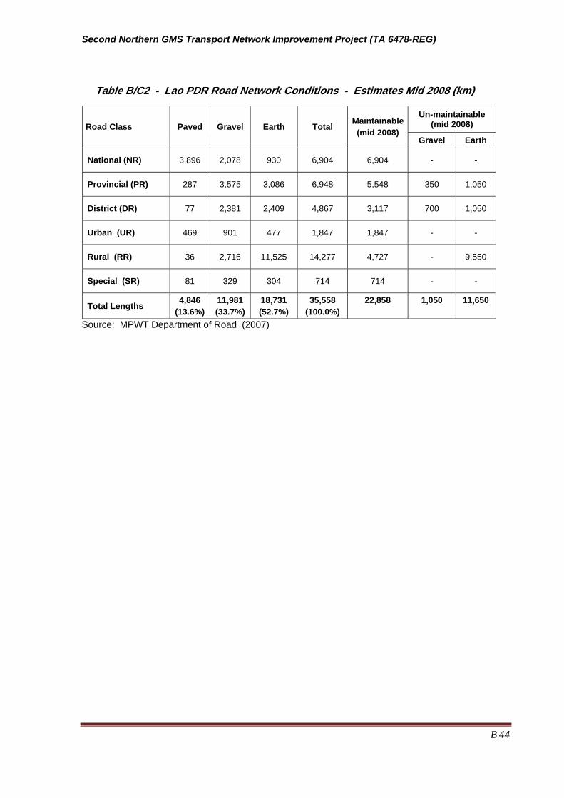
Second Northern GMS Transport Network Improvement Project (TA 6478-REG)
B 44
Table B/C2 - Lao PDR Road Network Conditions - Estimates Mid 2008 (km)
Source: MPWT Department of Road (2007)
Un-maintainable (mid 2008) Road Class Paved Gravel Earth Total Maintainable
(mid 2008) Gravel Earth
National (NR) 3,896 2,078 930 6,904 6,904 - -
Provincial (PR) 287 3,575 3,086 6,948 5,548 350 1,050
District (DR) 77 2,381 2,409 4,867 3,117 700 1,050
Urban (UR) 469 901 477 1,847 1,847 - -
Rural (RR) 36 2,716 11,525 14,277 4,727 - 9,550
Special (SR) 81 329 304 714 714 - -
Total Lengths 4,846 (13.6%)
11,981(33.7%)
18,731 (52.7%)
35,558 (100.0%)
22,858
1,050
11,650

Second Northern GMS Transport Network Improvement Project (TA 6478-REG)
B 45
Annex D of Part B RURAL ROADS Lao PDR
B/D 1 Introduction and Methodology 312. The rural road screening presented below is based on the local roads data used by the Local Roads Division of the Ministry of Public Works and Transport. The data was available from three existing systems, the Road Management System (RMS), the Provincial Maintenance Management System (PRoMMS) and the Community Road Model (CRM) developed for national, provincial and district wide road network planning respectively.
313. The district and rural roads data was collected by the district authorities and their road departments. The resulting socio economic data, some of which was collected in early 2009 included the following:
g) Population *;
h) Agricultural potential;
i) Non-agricultural potential;
j) Travel time to existing health services* ;
k) Travel time to primary schools* ;
l) Travel time to secondary schools* ;
m) Travel time to markets* ; and
n) Accessibility (months road is usable annually)*
Note. The items marked with an “*” were used to rate the quality of the road accessibility/access.
314. The social condition rating system used for key indicators is included in Attachment 1 to this appendix. D.
315. Engineering data available in the database included terrain type, existing road width, surface type and condition, road condition, drainage condition, number of culverts, number of bridges, level of maintainability, traffic levels, major defect types, accessibility constraint types, etc.
B/D 2 Identification of Candidate Roads 316. The candidate roads listed Table B/D2.1 below were identified following the review of available data and maps, discussions with LRD and also with the provincial and district authorities. The Houaphan DPWT and provincial officials also provided a list of their priorities. The primary criteria used to identify the candidate roads were:
• Roads needed to be connected directly to R6A, R6B and R6 (Viengxay to Namsoi) or were close to these sections but intersected with other roads in good condition; and
• Roads that connected to R6 between Viengxay and Phoulao (intersection with R1C and R1D). In this section the road works on R6 would be limited to minor alignment improvements.

Second Northern GMS Transport Network Improvement Project (TA 6478-REG)
B 46
Table B/D 2.1 - List of Candidate Roads
Road No. Category Link Length Starting Point End Point Proximity to Project
Road
3201 Provincial A 34.1 SoS School B. Nongkang Corridor Near Project
3202 Provincial A 36.0 Jct Rd No.6 B. Done B. Phieng Corridor
3205 District A 35.0 B. Nasala B. Songkhao Corridor G
3205 District B 30.0 B. Nasala B. Songkhao Corridor G
3205 District C 41.0 B. Nasala B. Songkhao Corridor G
3208 Rural A 8.0 B. Sophao B. Sombung Connects G
3223 Rural A 12.2 Jct Rd N.6 B. Nathong Huay Padong Corridor Near Project
3223 Rural B 6.0 Jct Rd N.6 B. Nathong Huay Padong Corridor Near Project
3238 Rural A 15.0 B. Longkhou B. Phonthong Connects
3239 Rural A 10.0 B. Phounmay B. Naheua Connects
3243 Rural A 21.6 Jct Rd No.6 B. Natok B. Pakhatay Corridor
3244 District A 15.6 Jct Rd N.6 B. Vek Jct Rd N.6 B. Phanang Corridor G
3254 Rural A 10.3 Jct Rd N.6B. Meuanghang B. Nakhoun Corridor
3255 Rural A 10.0 B. Meuanghom B. Danhung Connects
3413 Rural A 10.0 B. Khan B. Houyhom Corridor
3415 Rural A 2.8 Jct Rd No.6 B. Ham Bornamoun Connects
3475 Rural A 14.0 B. Khangkhong V/N Border Connects G
3481 Rural A 10.6 B. Phouxay Jct Rd N.6 B. Navid Corridor Near Project
3482 Rural A 4.0 B. Naloung B. Sart Connects
3483 Rural A 12.4 B. Meuangpou B. Pok Connects
3506 Rural A 3.0 B. Meuangpen B. Nampong Corridor
3509 Rural A 4.0 Phaku Nakham Corridor
3581 Rural A 5.0 B. Nathong B. Nadeua Corridor
3582 Rural A 18.0 B. Sopsay B. Mong Corridor
3583 Rural A 5.0 B. Khorhai B. Phongsad Corridor
B/D 3 Prioritizing the Candidate Roads 317. The prioritization process was based on scoring on 2 separate scoring systems, as follows
Access and accessibility rating - this was done by adding up the 1 to 5 rating for the following indicators:
• Road condition
• Length of time road closed per year;
• Travel time to existing health services;
• Travel time to primary schools;
• Travel time to secondary schools;
The rating were then ranked according to the ratings, the highest score being ranked number one.
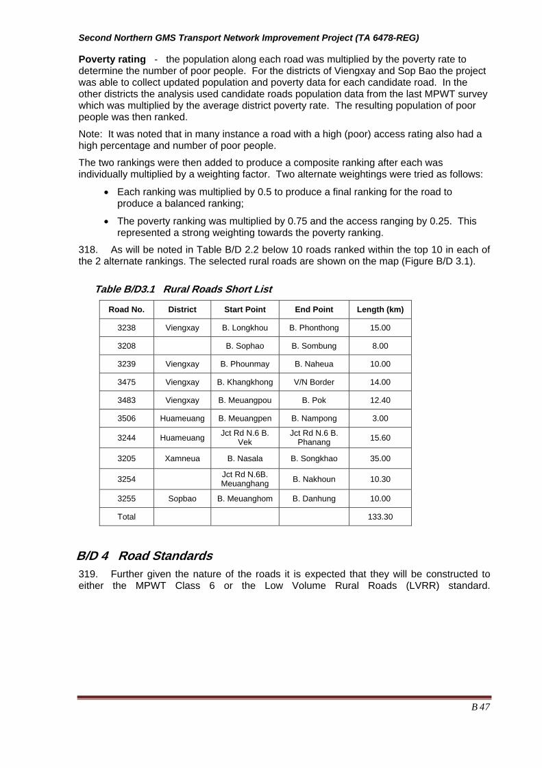
Second Northern GMS Transport Network Improvement Project (TA 6478-REG)
B 47
Poverty rating - the population along each road was multiplied by the poverty rate to determine the number of poor people. For the districts of Viengxay and Sop Bao the project was able to collect updated population and poverty data for each candidate road. In the other districts the analysis used candidate roads population data from the last MPWT survey which was multiplied by the average district poverty rate. The resulting population of poor people was then ranked.
Note: It was noted that in many instance a road with a high (poor) access rating also had a high percentage and number of poor people.
The two rankings were then added to produce a composite ranking after each was individually multiplied by a weighting factor. Two alternate weightings were tried as follows:
• Each ranking was multiplied by 0.5 to produce a final ranking for the road to produce a balanced ranking;
• The poverty ranking was multiplied by 0.75 and the access ranging by 0.25. This represented a strong weighting towards the poverty ranking.
318. As will be noted in Table B/D 2.2 below 10 roads ranked within the top 10 in each of the 2 alternate rankings. The selected rural roads are shown on the map (Figure B/D 3.1).
Table B/D3.1 Rural Roads Short List
Road No. District Start Point End Point Length (km)
3238 Viengxay B. Longkhou B. Phonthong 15.00
3208 B. Sophao B. Sombung 8.00
3239 Viengxay B. Phounmay B. Naheua 10.00
3475 Viengxay B. Khangkhong V/N Border 14.00
3483 Viengxay B. Meuangpou B. Pok 12.40
3506 Huameuang B. Meuangpen B. Nampong 3.00
3244 Huameuang Jct Rd N.6 B. Vek
Jct Rd N.6 B. Phanang 15.60
3205 Xamneua B. Nasala B. Songkhao 35.00
3254 Jct Rd N.6B. Meuanghang B. Nakhoun 10.30
3255 Sopbao B. Meuanghom B. Danhung 10.00
Total 133.30
B/D 4 Road Standards 319. Further given the nature of the roads it is expected that they will be constructed to either the MPWT Class 6 or the Low Volume Rural Roads (LVRR) standard.

Second Northern GMS Transport Network Improvement Project (TA 6478-REG)
B 48
Figure B/D3.1 Rural Roads Map

Second Northern GMS Transport Network Improvement Project (TA 6478-REG)
B 49
B/D 5 Proposed work of Rural Roads 320. Horizontal and vertical alignments of the selected rural roads have not been required any improving as preliminary TA consultant’s surveys. Proposed works of selected rural roads are showing in Table B/D 5.1 Proposed Work of Rural Roads. The proposed works are base on Rural Road Standard and engineering surveys.
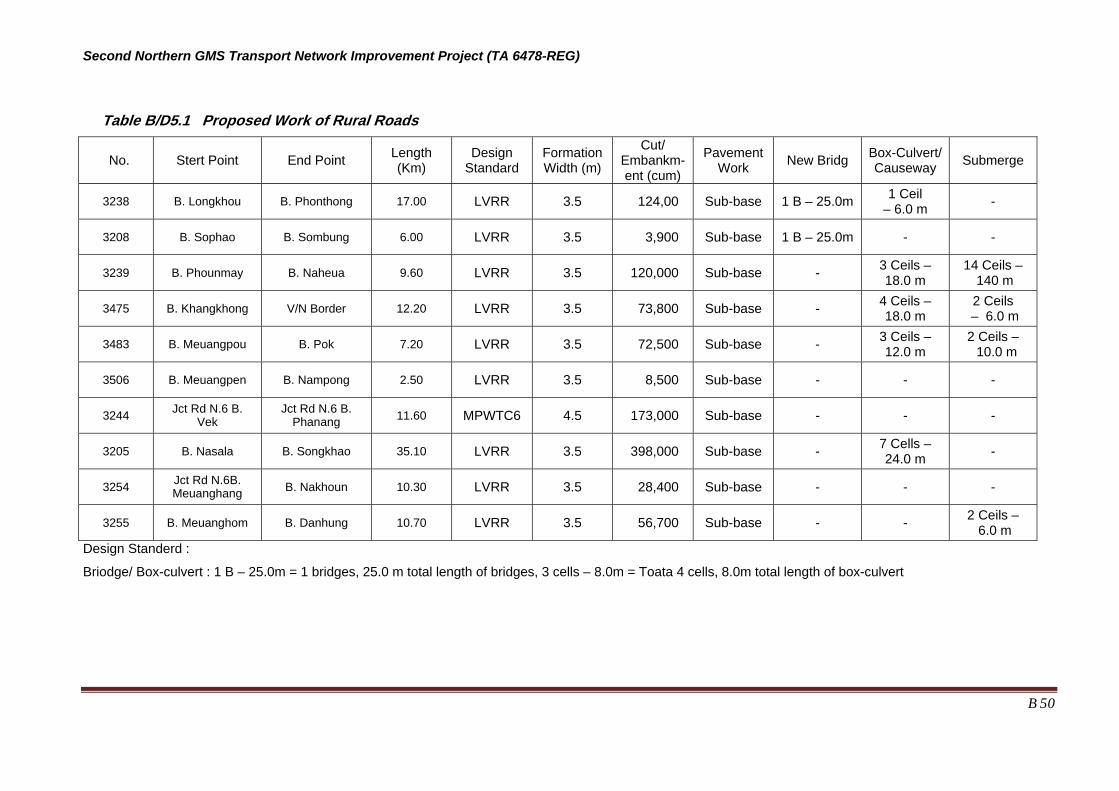
Second Northern GMS Transport Network Improvement Project (TA 6478-REG)
B 50
Table B/D5.1 Proposed Work of Rural Roads
No. Stert Point End Point Length (Km)
Design Standard
Formation Width (m)
Cut/ Embankm-ent (cum)
Pavement Work New Bridg Box-Culvert/
Causeway Submerge
3238 B. Longkhou B. Phonthong 17.00 LVRR 3.5 124,00 Sub-base 1 B – 25.0m 1 Ceil – 6.0 m -
3208 B. Sophao B. Sombung 6.00 LVRR 3.5 3,900 Sub-base 1 B – 25.0m - -
3239 B. Phounmay B. Naheua 9.60 LVRR 3.5 120,000 Sub-base - 3 Ceils – 18.0 m
14 Ceils – 140 m
3475 B. Khangkhong V/N Border 12.20 LVRR 3.5 73,800 Sub-base - 4 Ceils – 18.0 m
2 Ceils – 6.0 m
3483 B. Meuangpou B. Pok 7.20 LVRR 3.5 72,500 Sub-base - 3 Ceils – 12.0 m
2 Ceils – 10.0 m
3506 B. Meuangpen B. Nampong 2.50 LVRR 3.5 8,500 Sub-base - - -
3244 Jct Rd N.6 B. Vek
Jct Rd N.6 B. Phanang 11.60 MPWTC6 4.5 173,000 Sub-base - - -
3205 B. Nasala B. Songkhao 35.10 LVRR 3.5 398,000 Sub-base - 7 Cells – 24.0 m -
3254 Jct Rd N.6B. Meuanghang B. Nakhoun 10.30 LVRR 3.5 28,400 Sub-base - - -
3255 B. Meuanghom B. Danhung 10.70 LVRR 3.5 56,700 Sub-base - - 2 Ceils – 6.0 m
Design Standerd :
Briodge/ Box-culvert : 1 B – 25.0m = 1 bridges, 25.0 m total length of bridges, 3 cells – 8.0m = Toata 4 cells, 8.0m total length of box-culvert
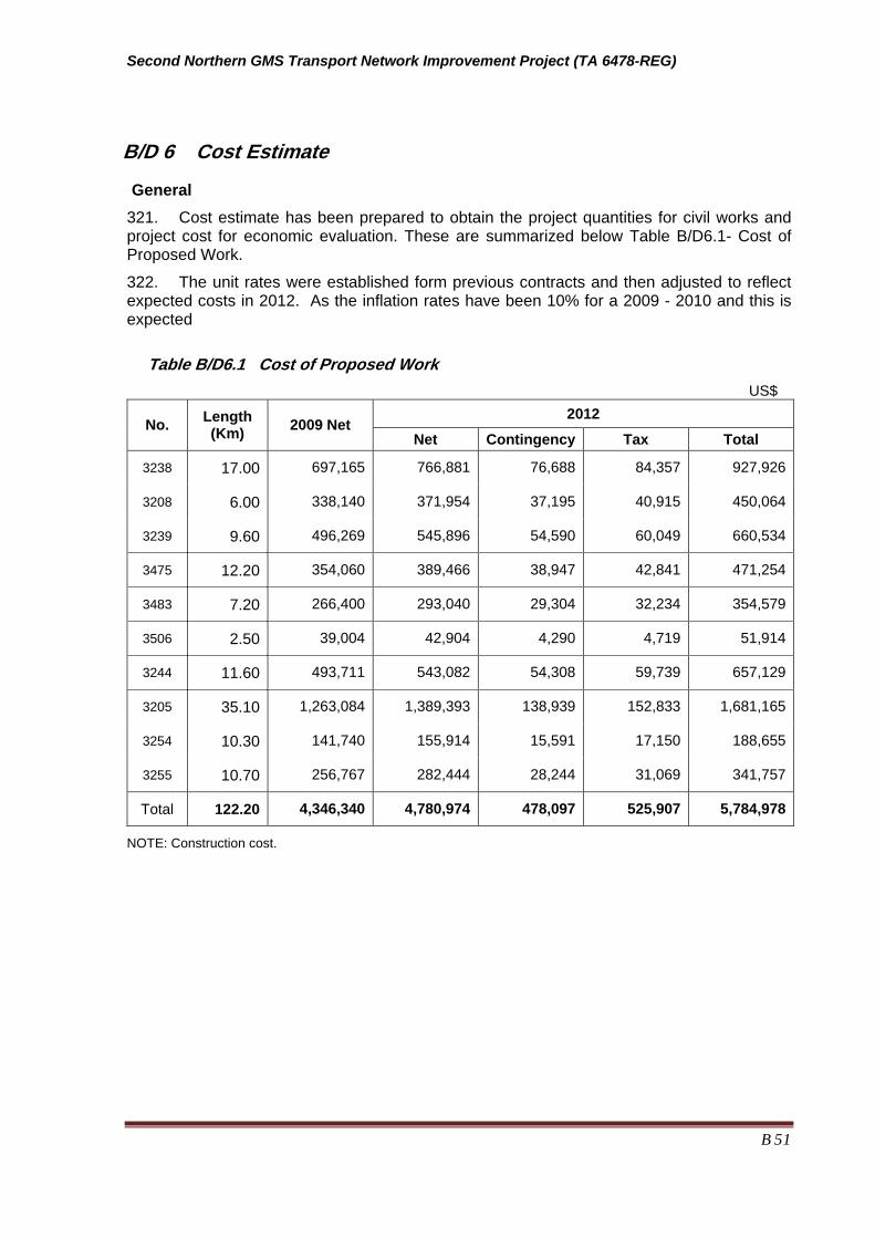
Second Northern GMS Transport Network Improvement Project (TA 6478-REG)
B 51
B/D 6 Cost Estimate
General 321. Cost estimate has been prepared to obtain the project quantities for civil works and project cost for economic evaluation. These are summarized below Table B/D6.1- Cost of Proposed Work.
322. The unit rates were established form previous contracts and then adjusted to reflect expected costs in 2012. As the inflation rates have been 10% for a 2009 - 2010 and this is expected
Table B/D6.1 Cost of Proposed Work US$
2012 No. Length
(Km) 2009 Net Net Contingency Tax Total
3238 17.00 697,165 766,881 76,688 84,357 927,926
3208 6.00 338,140 371,954 37,195 40,915 450,064
3239 9.60 496,269 545,896 54,590 60,049 660,534
3475 12.20 354,060 389,466 38,947 42,841 471,254
3483 7.20 266,400 293,040 29,304 32,234 354,579
3506 2.50 39,004 42,904 4,290 4,719 51,914
3244 11.60 493,711 543,082 54,308 59,739 657,129
3205 35.10 1,263,084 1,389,393 138,939 152,833 1,681,165
3254 10.30 141,740 155,914 15,591 17,150 188,655
3255 10.70 256,767 282,444 28,244 31,069 341,757
Total 122.20 4,346,340 4,780,974 478,097 525,907 5,784,978
NOTE: Construction cost.

Second Northern GMS Transport Network Improvement Project (TA 6478-REG)
B 52
Attachment 1
Indicator Scoring System LAO PDR.
Indicator 01: Agriculture Potential 1 = The Area Around the Road has a Low Agricultural Potential (if the road is improved or
constructed the agriculture production and marketing of products will not change much). 3 = The Area Around the Road has a Medium Agricultural Potential (if the road is improved or
constructed the agriculture production and marketing of products will increase). 5 = The Area Around the Road has a High Agricultural Potential (if the road is improved or
constructed the agriculture production and marketing of products will increase a lot).
Indicator 02: Other Non-Agriculture Potential 1 = The Area Around the Road has a Low Non-Agricultural Potential (if the road is improved or
constructed the non-agriculture production and marketing of products will not change much). 3 = The Area Around the Road has a Medium Non-Agricultural Potential (if the road is improved or
constructed the non-agriculture production and marketing of products will increase). 5 = The Area Around the Road has a High Non-Agricultural Potential (if the road is improved or
constructed the non-agriculture production and marketing of products will increase a lot).
Indicator 03: Existing Health Services Used by Population 1 = Health Services are Nearby (nearest hospital is less than 2 hours travel) 3 = Health Services are an Average Distance Away (nearest hospital is less than 5 hours travel) 5 = Health Services are Far Away (nearest hospital is more than 5 hours travel)
Indicator 04: Existing Primary School Used by Population 1 = Primary School are Nearby (no travel time required – school within village) 3 = Primary School are an Average Distance Away (nearest Primary School is less than 2 hours
travel) 5 = Primary School are Far Away (nearest Primary School is more than 2 hours travel)
Indicator 05: Existing Secondary School Used by Population 1 = Secondary School are Nearby (nearest Secondary School is less than 2 hours travel) 3 = Secondary School are an Average Distance Away (nearest Secondary School is less than 5
hours travel) 5 = Secondary School are Far Away (nearest Secondary School is more than
Indicator 07: Present Access to the Markets 1 = Good (main market is within an average of 2 hours travel from the villages along the road) 3 = Fair (main market is between an average of 2 to 5 hours travel from the villages along the
road) 5 = Bad (main market, on the average, is more than 5 hours travel away from the villages along
the road)
Indicator 08: Road Condition before Improvement 1 = Existing Road is in Fair Condition (trafficable during most of the year) 3 = Existing Road is in Bad Condition (trafficable less than 6 months per year) 5 = No Existing Road or Road is Never Trafficable

Second Northern GMS Transport Network Improvement Project (TA 6478-REG)
B 53
Annex E of Part B
Pavement Analysis - Lao PDR
B/E 1.1 GENERAL
323. The pavement investigation was carried out for the national road 6 from Section: Halong to Nameo (Km 119+000 -175+020), on the national road 6A from Section: Halong to Sopbao (from intersection with R6 to Km 62+550) and on the national road 6B from Section: Intersection with R6A to road QL 43 (Pahang), in Houaphan Province. The results of the investigation were used for the preliminary engineering design of the road pavement, which is a part of The Second Northern GMS Transport Network Improvement Project. The pavement investigation was carried out by LAO Consulting Group (LCG), Lao PDR under the supervision of International Pavement/Material Engineer. The exploration work commenced on 9th May 2009 and was completed on 14th May 2009.The field work was undertaken during the dry season.
B/E 1.2 EXISTING ROAD CONDITIONS
324. Pavement condition survey plays an important role in the investigation and determining likely pavement improvement option. Visual observations were carried out along the entire project corridor to examine pavement distress and functional efficiency. The method suggested in HDM manual was used to assess distress areas (cracks, raveling and potholes) and estimated as a percentage of the total carriageway. The overall observed road conditions are summarized below:
A. Road 6 Road 6 is located in hilly to mountainous terrain, has a narrow paved surface width of 3.5 to 4 meters and shoulders of approx 0.75 meters. Road improvement work will include widening of road formation to meet Lao PDR Design Standards. Cracks, ruts, potholes and failures have occurred in minor to sever ranges which causing a quick damaging of the road and has created demands for rehabilitation/reconstruction. Shoulders of some sections need upgrading by SBST surfacing as per proposed section types. The analysis showed that the project roads need to be widened to 6.5 meter formation with 2 x 2.75 meter paved traffic lanes and sealed shoulders of 0.5 meters).
B. Road- 6A Road 6A is a narrow paved road (4 metres) for the first 11 kilometers east of Hang Long after which the road is a narrow gravel road that is very rough in places. The road passes through rolling to mountainous terrain for the first 35 kilometers after which is passes through flat to rolling terrain. Sections need widening to meet requirements of the proposed section types (Type-A/ Type-B/ Type-C/Type- D/Type-E). Conditions of paved section varied greatly with roughness levels being from IRI 6 to 12, most sections had a roughness of IRI 7 to 9. Ride conditions of unpaved road sections are generally fair to poor with IRI levels of 8 to 15 plus. Ruts and failures (potholes) have occurred in minor to sever ranges which causing a quick damaging of the road and has created demands for rehabilitation/pavement reconstruction.
C. Road- 6B It is located in hilly to mountainous terrain and is very rough especially on the broken macadam pavements. It is observed in the road inventory data that existing formation is 5.0 m width. Sections need widening to meet requirements of Lao PDR Design Standards. Surface of the existing road is mostly of gravel surface with sections of damaged macadam pavement. Ruts and failures (potholes) have occurred in minor to sever ranges. Ride quality varies significantly with most having an estimated IRI of between 8 and 15. Complete

Second Northern GMS Transport Network Improvement Project (TA 6478-REG)
B 54
pavement and subgrade failures are also present with rut depths exceeding 10 cm for a number of kilometers. Macadam pavement section towards the eastern end of the road is badly damaged with estimated IRI of more than 15. 325. Project road pavement conditions are summarized in Table B/E1.2.1.
Table B/E1.2.1: Existing Road Pavement Condition
From (Km)
To (Km)
Length (km)
Year Rehab
Existing SN
PavementWidth (m)
Shoulder Width (m)
Surface Type
Rough-ness (IRI)
Crack (%)
Rut depth (mm)
Patching (%)
119 121.46 2.46 2000 1.50 3.8 1 Sprayed Seal 5 20 10 20
121.46 126.69 5.23 2000 1.50 3.8 1 Sprayed Seal 5 20 25 20
126.69 131.31 4.62 2000 1.50 3.8 1 Sprayed Seal 5 20 15 20
131.31 141.67 10.36 2000 1.50 4 1 Sprayed Seal 5 20 15 20
141.67 152.54 10.87 2000 1.50 4.5 0.75 Sprayed Seal 5 20 15 20
152.54 158.59 6.05 2000 1.50 3.5 0.75 Sprayed Seal 5 20 15 20
158.59 169.26 10.67 2000 1.50 4 0.5 Sprayed Seal 5 20 20 35
Roa
d 6
169.26 175.00 5.74 2000 1.50 4 0.5 Sprayed Seal 7 20 25 45
0 1.22 1.22 2000 1.5 3.5 0.75 Sprayed Seal 5 15 10 15
1.22 11.16 9.94 2000 1.5 3.5 0.75 Sprayed Seal 5 15 10 15
11.16 20.09 8.93 1995 0.5 5.5 0 Gravel 7 0 0 0
20.09 22.12 2.03 1995 0.5 5.5 0 Gravel 10 0 0 0
22.12 24.86 2.74 1995 0.5 5.5 0 Gravel 10 0 0 0
24.86 34.70 9.84 1995 0.5 5.5 0 Gravel 10 0 0 0
34.70 36.83 2.13 1995 0.5 5.5 0 Gravel 8 0 0 0
Sect
ion
6A
36.83 62.40 25.57 1995 0.5 5.5 0 Gravel 8 0 0 0
0 9.96 9.96 1995 0.5 5 0 Gravel 8 0 0 0
9.96 10.86 0.90 1995 0.5 5 0 Mac Failed 12 100 20 70
10.86 19.58 8.73 1995 0.5 5 0 Gravel 8 0 0 0
19.58 23.64 4.06 1995 0.5 5 0 Mac Failed 15 100 20 50
Sect
ion
6B
23.64 24.86 1.22 1995 0.5 5 0 Gravel 10 0 0 0

Second Northern GMS Transport Network Improvement Project (TA 6478-REG)
B 55
B/E1.3 FIELD and LABORATORY INVESTIGATION 326. Field pavement and geotechnical instigation was carried out to support the proper design of the road rehabilitation work. Full details relative to area geology, sampling and testing of the existing roadbed, calculation of CBR values and other geotechnical data which support the conclusions and recommendations included in this section.
327. The following works were undertaken to determine in-situ base course and sub-grade strength, pavement condition, laboratory CBR and properties of the existing road materials:
• Sampling of base course and sub-grade materials were conducted by hand at test pit. • Field density tests were conducted in the test pits along the alignment of the existing
road section to determine the in-situ density of the soils encountered. • Dynamic Cone Penetrometer (DCP) tests. • Laboratory tests were conducted on soil samples from the site in addition to
classification tests, compaction tests were conducted to determine the Moisture-Density relationship (OMC-MDD) and California Bearing Ratio (CBR) test also conducted to determine the bearing capacity of the soils.
328. Dynamic Cone Penetrometer (DCP) Tests were carried out at 45 locations along the existing road primarily for the sampling and testing of existing pavement materials and subgrade, as well as performing in-situ CBR tests using DCP equipment in order to facilitate preliminary pavement design.
329. Dynamic Cone Penetrometer (DCP) tests were carried out with Transport Road Research Laboratory (TRRL) Dynamic Cone Penetrometer MODEL A 2456. The 600 cone was advanced with blows from an 8 kg hammer dropping freely from 575 mm. The cone was advanced to a maximum depth of 1.30 m below the ground level. As the cone penetrates into the pavement, the number of blows and the penetration depth are recorded onto a Test data sheet and then plotted onto a penetration graph.
330. The number of blows against penetration of the cone was recorded and this data was used to calculate layer depth for average CBR determination, the field CBR is established by the following DCP-CBR relationship equation:
Log10 (CBR) = 2.632-1.28 Log10 (DCP) 331. DCP is the average Penetrometer in mm per blow for each layer. Summary of DCP tests are showed in Annex 1 that represent the strength of existing layers and sub-grade strength at selected test locations.
332. In-situ density of the soil was determined using the sand cone replacement method (AASHTO T- 191).
333. Test pits were dug along the existing road alignment at 15 locations. The size of test pits was one cubic meter, explored materials to a maximum depth of one meter below the surface. Record of groundwater level was taken wherever free water was encountered during excavation of test pits. A bulk samples collected from the representative test pits were tested in laboratory to determine their engineering properties. Tests included natural moisture content, sieve analysis, Atterberg limits, and CBR. After collecting the samples, the test pits were backfilled and adequately compacted by hand whilst filling. The materials encountered by test pits were logged in accordance with Unified Soil Classification System (USCS).

Second Northern GMS Transport Network Improvement Project (TA 6478-REG)
B 56
334. The laboratory test comprised:
- Sieve Analysis tests were conducted in accordance with AASHTO T 88 - Atterberg Limit tests were conducted in accordance with AASHTO T 89, T 90 - Natural water content test were conducted in accordance with AASHTO T 265 - Compaction tests were conducted in accordance with AASHTO T 180
- California Bearing Ratio (CBR) tests were conducted in accordance with AASHTO T 193 (soaked 4days)
335. Summary of laboratory test results are shown in Annex 2. Results of laboratory tests were carefully analyzed and materials parameters required for pavement design were calculated.
336. CBR values obtained from DCP tests were observed significantly different from that obtained from laboratory CBR testing (soaking minimum 4 days). DCP test may produced erroneous results owing to various factor such as excessive dryness of materials and excessive coarse/gravel type particles in the bed. Considering the above facts, laboratory CBR values were mainly adopted for pavement evaluation and design.
337. In road 6 two stretches was sorted out where existing sub grade materials had CBR values (Min 4 days soaked) less than 2% at 95% compaction. Replacement by suitable sub grade materials obtained from the borrow pits is recommended as cost effective solution.
338. Accurate data of rainfall and subsoil moisture condition could not be collected. However, based on the geo-climatic data, it was determined that 25% times of the year road bed soil moisture levels reach to saturation moisture levels.
339.
B/E1.4 PAVEMENT MATERIAL OPTIONS and ALTERNATIVES 340. Based on the field and laboratory test results, the existing aggregate layer/layers do not meet the specification of road base/Sub base materials. It is proposed that existing aggregate materials shall be replaced with appropriate crushed/screened materials or can be reused after processing to specified quality of the relevant items. The soil condition along the existing road alignment is proposed to be used for sub-grade material, but there are some locations where stabilizing or improving the subgrade will be required. A select subgrade (CBR of 8~10%) can be used to minimize the expensive subbase material.
B/E1.5 PROPOSED PAVEMENT WORKS 341. Poor pavement performance is an issue in LAO PDR with pavements often having to be rehabilitated just about at half of design life. Reasons for the problem range from poor design, overloading and inadequate maintenance.
342. The failures occurred in the “outer wheel path” of the traffic lanes because of the practice of constructing roads with unpaved earth/gravel shoulders. This is not recommended anywhere but especially for wet climates like Lao PDR where there is a lengthy wet season. In-situ moisture measurements made during the project demonstrated this situation with in-situ moisture contents up to double the optimum moisture content (OMC) in a significant number of locations.
343. The proposed pavements will have full width (each layer extending for the full width of the road formation) and have sealed shoulders thus allowing good drainage. Specifications will require that subgrade samples are soaked until they stop swelling (or are soaked for 10 days as now specified in some LAO PDR contracts) and that subbase materials have a maximum plasticity Index (PI) of 9%.
•
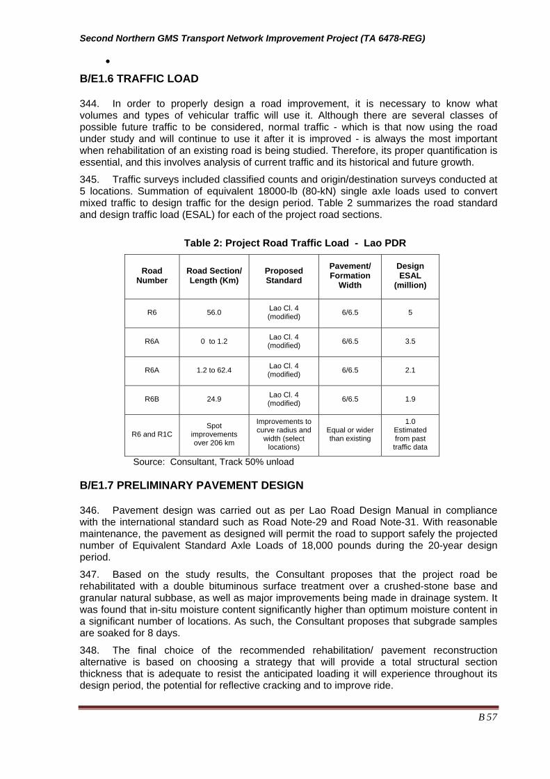
Second Northern GMS Transport Network Improvement Project (TA 6478-REG)
B 57
•
B/E1.6 TRAFFIC LOAD 344. In order to properly design a road improvement, it is necessary to know what volumes and types of vehicular traffic will use it. Although there are several classes of possible future traffic to be considered, normal traffic - which is that now using the road under study and will continue to use it after it is improved - is always the most important when rehabilitation of an existing road is being studied. Therefore, its proper quantification is essential, and this involves analysis of current traffic and its historical and future growth.
345. Traffic surveys included classified counts and origin/destination surveys conducted at 5 locations. Summation of equivalent 18000-lb (80-kN) single axle loads used to convert mixed traffic to design traffic for the design period. Table 2 summarizes the road standard and design traffic load (ESAL) for each of the project road sections.
Table 2: Project Road Traffic Load - Lao PDR
Road Number
Road Section/ Length (Km)
Proposed Standard
Pavement/ Formation
Width
Design ESAL
(million)
R6 56.0 Lao Cl. 4 (modified) 6/6.5 5
R6A 0 to 1.2 Lao Cl. 4 (modified) 6/6.5 3.5
R6A 1.2 to 62.4 Lao Cl. 4 (modified) 6/6.5 2.1
R6B 24.9 Lao Cl. 4 (modified) 6/6.5 1.9
R6 and R1C Spot
improvements over 206 km
Improvements to curve radius and
width (select locations)
Equal or wider than existing
1.0 Estimated from past traffic data
Source: Consultant, Track 50% unload B/E1.7 PRELIMINARY PAVEMENT DESIGN 346. Pavement design was carried out as per Lao Road Design Manual in compliance with the international standard such as Road Note-29 and Road Note-31. With reasonable maintenance, the pavement as designed will permit the road to support safely the projected number of Equivalent Standard Axle Loads of 18,000 pounds during the 20-year design period.
347. Based on the study results, the Consultant proposes that the project road be rehabilitated with a double bituminous surface treatment over a crushed-stone base and granular natural subbase, as well as major improvements being made in drainage system. It was found that in-situ moisture content significantly higher than optimum moisture content in a significant number of locations. As such, the Consultant proposes that subgrade samples are soaked for 8 days.
348. The final choice of the recommended rehabilitation/ pavement reconstruction alternative is based on choosing a strategy that will provide a total structural section thickness that is adequate to resist the anticipated loading it will experience throughout its design period, the potential for reflective cracking and to improve ride.

Second Northern GMS Transport Network Improvement Project (TA 6478-REG)
B 58
349. Based on an analysis of traffic data, observations during a number of field inspection and successive discussions with the client it was decided that all roads would be constructed to a LAO Class 5 (modified) standard.
350. The parameters for the pavement design were as follow:
Design Period: The period of time that a rehabilitated pavement structural section is designed to perform before reaching its terminal serviceability or a condition that requires major rehabilitation or reconstruction; this is also referred to as the performance period. Equivalent Single Axle Loads (ESAL’s): Summation of equivalent 18000-lb (80-kN) single axle loads used to convert mixed traffic to design traffic for the design period. Structural Section: The planned, engineering-designed layers of specified materials (normally consisting of subbase, base, and pavement surface) placed over the basement soil to support the traffic loads anticipated to be accumulated and applied during the design period. The structural section is also commonly called the pavement structural section. Structural Section Drainage System: A drainage system used for both asphalt/bituminous pavements consisting of a treated permeable base layer and a collector system which includes a slotted pipe encapsulated in treated permeable material. Drainage must be kept operating efficiently during the life of the road to prevent the strength/CBR decreasing through weakening of the foundation by a rising water table. Subbase: A layer of aggregate of designed thickness and specified quality placed on the basement soils as the foundation for a base. Subgrade: That portion of the roadbed on which pavement surfacing, base, subbase, or a layer of any other material is placed. 351. Design Equivalent Standard Axle (ESAL) was determined from traffic counts and projected growth rate and damaging factors were calculated from the axle load data.
352. Subgrade CBR values of 7 was assumed to be achievable by application of sub grade materials collected from borrow pit as revealed in the CBR value of Lab tests of the sub grade materials of the sources. At some sections subgrade CBR value of 3 was used with the aid of an additional capping layer. Based on the test pit bore logs and laboratory tests results, subgrade soil PI of less than 10 can be reasonably assumed. Considering the water level near the formation level at prolonged wet period, a subgrade strength class of S3 was assumed as per Road Note 31 Table 3.2.
353. Preliminary pavement design was based on Road note 31 “Structural Catalogue”. Subgtade CBR was assumed from knowledge of various investigation and field inspection and traffic class was determined as stated above. These two parameters was imposed on the chart to determine thickness of Subase, Road base and improved sub grade.
354. Pavements will also include a drainage layer because subgrade, wetter than the optimum moisture content (OMC) was encountered in 35 to 50 % of the test pits on all the road sections.
355. Based on the preliminary design, the thickness of pavement layers were determined and presented in Table - 3 below.
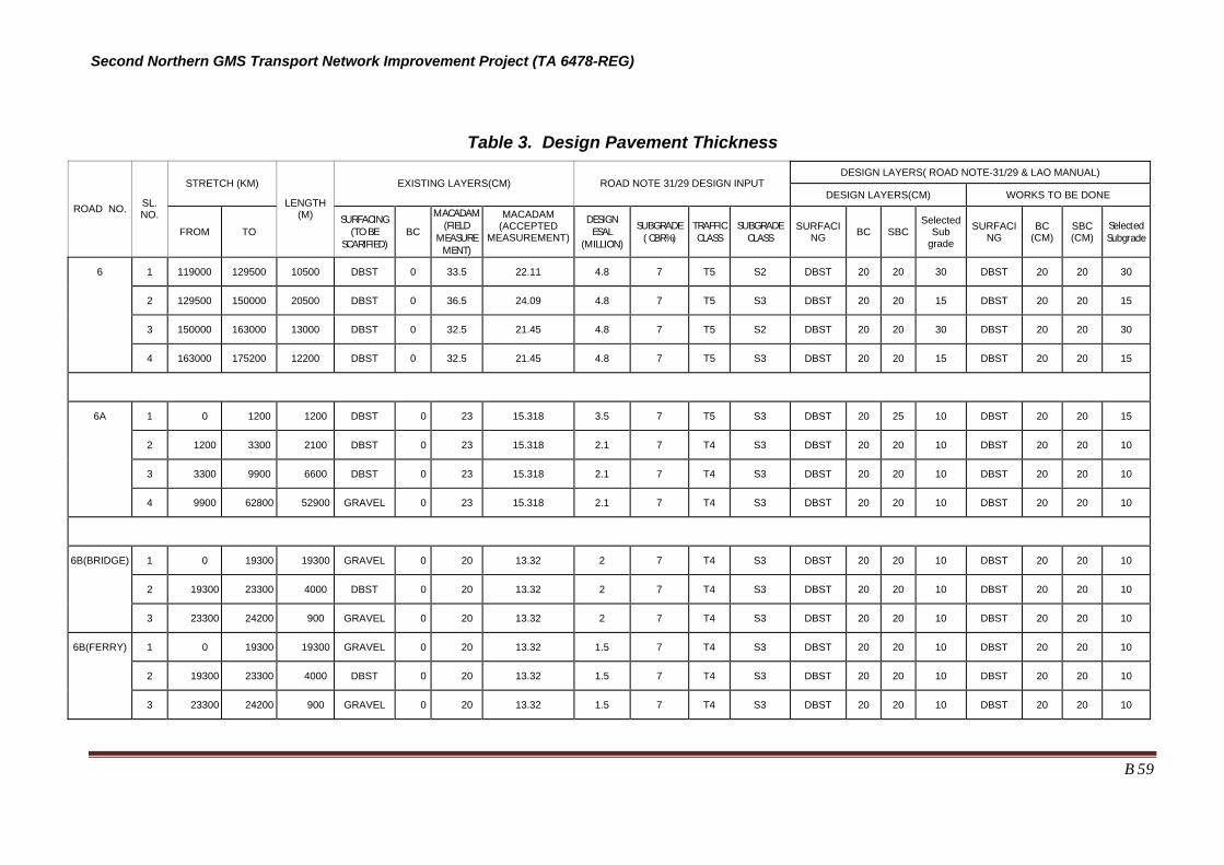
Second Northern GMS Transport Network Improvement Project (TA 6478-REG)
B 59
Table 3. Design Pavement Thickness DESIGN LAYERS( ROAD NOTE-31/29 & LAO MANUAL)
STRETCH (KM) EXISTING LAYERS(CM) ROAD NOTE 31/29 DESIGN INPUT DESIGN LAYERS(CM) WORKS TO BE DONE
ROAD NO. SL. NO.
FROM TO
LENGTH (M) SURFACING
(TO BE SCARIFIED)
BC
MACADAM(FIELD
MEASUREMENT)
MACADAM (ACCEPTED
MEASUREMENT)
DESIGN ESAL
(MILLION)
SUBGRADE ( CBR%)
TRAFFICCLASS
SUBGRADECLASS
SURFACING BC SBC
SelectedSub
grade
SURFACING
BC (CM)
SBC (CM)
Selected Subgrade
6 1 119000 129500 10500 DBST 0 33.5 22.11 4.8 7 T5 S2 DBST 20 20 30 DBST 20 20 30
2 129500 150000 20500 DBST 0 36.5 24.09 4.8 7 T5 S3 DBST 20 20 15 DBST 20 20 15
3 150000 163000 13000 DBST 0 32.5 21.45 4.8 7 T5 S2 DBST 20 20 30 DBST 20 20 30
4 163000 175200 12200 DBST 0 32.5 21.45 4.8 7 T5 S3 DBST 20 20 15 DBST 20 20 15
6A 1 0 1200 1200 DBST 0 23 15.318 3.5 7 T5 S3 DBST 20 25 10 DBST 20 20 15
2 1200 3300 2100 DBST 0 23 15.318 2.1 7 T4 S3 DBST 20 20 10 DBST 20 20 10
3 3300 9900 6600 DBST 0 23 15.318 2.1 7 T4 S3 DBST 20 20 10 DBST 20 20 10
4 9900 62800 52900 GRAVEL 0 23 15.318 2.1 7 T4 S3 DBST 20 20 10 DBST 20 20 10
6B(BRIDGE) 1 0 19300 19300 GRAVEL 0 20 13.32 2 7 T4 S3 DBST 20 20 10 DBST 20 20 10
2 19300 23300 4000 DBST 0 20 13.32 2 7 T4 S3 DBST 20 20 10 DBST 20 20 10
3 23300 24200 900 GRAVEL 0 20 13.32 2 7 T4 S3 DBST 20 20 10 DBST 20 20 10
6B(FERRY) 1 0 19300 19300 GRAVEL 0 20 13.32 1.5 7 T4 S3 DBST 20 20 10 DBST 20 20 10
2 19300 23300 4000 DBST 0 20 13.32 1.5 7 T4 S3 DBST 20 20 10 DBST 20 20 10
3 23300 24200 900 GRAVEL 0 20 13.32 1.5 7 T4 S3 DBST 20 20 10 DBST 20 20 10

Second Northern GMS Transport Network Improvement Project (TA 6478-REG)
B 60
B/E1.8 MATERIALS SOURCE and QUARRY INVESTIGATION 356. Field and laboratory investigations were performed in order to determine the location, quality and available quantities of borrow-pit materials needed in the rehabilitation work. The work commenced on 9th May 2009 and was completed on 15th May 2009 and was carried out by LCG material engineer under the supervision of International Pavement/Material Engineer.
357. Principal objectives of those activities were the following:
• Locate, and sample and test materials from, possible borrow pits along the study road, or nearby. Materials required include fill for embankments, select fill for subgrade improvement as needed, subbase, and aggregates for base and asphaltic surface.
• Determine required characteristics and quantities of materials for the new pavement structure, and estimate the approximate volume of suitable material which can be obtained from identified sites for the various pavement layers.
a. Construction materials survey 358. After a reconnaissance survey in the project area along the road alignment the suitable sources of materials were selected and samples of construction were collected for testing and analysis. Borrow pits were found at 5 locations and Quarries were found at 8 locations and 2 locations river sand.
b. Laboratory Test 359. Soil samples collected from the borrow pits, the river sand sources and quarry were delivered to laboratory of Sukkaseum Road and Bridge Architect Survey Design in Vientiane Capital and performed testing in order to determine the engineering properties.
360. Test performed for the borrow pit samples were as follow:
(1) Sieve Analysis tests were conducted in accordance with AASHTO T88. (2) Atterberg Limit tests were conducted in accordance with AASHTO T89 and T90 (3) Compaction tests were conducted in accordance with AASHTO T180 method D (4) California Bearing Ratio (CBR) tests were conducted in accordance with AASHTO
T193 (4 days soaked) 361. Tests performed for Quarry sources and river sand samples are as follow:
(1) Sieve Analysis of fine aggregate AASHTO T27 (2) Fineness Modulus (FM) (3) Organic Impurity AASHTO T21 (4) Los Angeles Abrasion test AASHTO T96 (5) Unit Weight AASHTO T19 (6) Specific Gravity AASHTO T84 and T85
362. Material sources, preliminary assessments and approximate quantities are summarized below.

Second Northern GMS Transport Network Improvement Project (TA 6478-REG)
B 61
Table 4: Material Characteristics and volume available in Sand and Stone Quarry
Sl. No.
Source Identity Road Location LAA
Value%
finer .075 mm
Soil-Classification Quantity Remarks
1 Q3 R-6 Km. 11.000 25.2 Stone >20000
Cum.
Crushed and Graded materials can be used as Road base/Sub base materials
2 Q4 R-6 Km. 101.500 24.6 Stone >180000
Crushed and Graded materials can be used as Road base/Sub base materials
3 Q5 R-6 Km. 165.800 35.9 Stone >6000
Cum.
Crushed and Graded materials can be used as Road base/Sub base materials
4 Q6 R-6 KM. 130.200 23.8 Stone >125000
Cum.
Crushed and Graded materials can be used as Road base/Sub base materials
5 Q7 R-6A Km. 34.000 28.9 Stone >6000
Cum.
Crushed and Graded materials can be used as Road base/Sub base materials
6 Q8 R-6B Km. 9.000 26.3 Stone >150000
Cum.
Crushed and Graded materials can be used as Road base/Sub base materials
7 RS-1 R-6A Km. 4.000 0.5 River Sand >2000
Cum.
Can be mixed with Road base/Sub base
8 RS-2 R-6A Km. 13.000 0.5 River Sand >2000
Cum.
Can be mixed with Road base/Sub base
Table 5: Material Characteristics and volume available in Borrow Pits
Sl. No.
Source Identity Road Location PI
value% finer (.075 mm)
Soil-Classificatio
n Quantit
y Remarks
1 BP-o1 R-6 Km. 119.000 6.5 28.23 Clayey sand
mixed with some Gravel
>40000 Cum.
Materials can be used as Improved Sub grade materials
2 BP-02 R-6A Km.58.500 19.9 46 Clayey sand
mixed with some Gravel
>24000 Cum.
Materials can be used as Improved Sub grade materials
3 BP-03 R-6A Km.46.000 13.4 46 Clayey sand
mixed with some Gravel
>20000 Cum.
Materials can be used as Improved Sub grade materials

Second Northern GMS Transport Network Improvement Project (TA 6478-REG)
B 62
4 BP-04 R-6B KM.9.000 13.1 28.6
Clayey sand mixed with some cracked stone
>16000 Cum.
Materials can be used as Improved Sub grade materials
5 BP-05 R-6B Km.16.600 12.7 30.3
Clayey sand mixed with some cracked stone
>12000 Cum.
Materials can be used as Improved Sub grade materials
363. Based on the observations and testing, borrow pit materials can be used as improved sub grade and stone can be used for road base/sub base after processing.
B/E1.9 RECOMMENDATION 364. The proposed design was based on limited field observation and field/laboratory test results. As such, Consultant recommends the following at detailed design stage:
i) The road works will include the widening of the existing road formation. This will include preparatory works, scarifying and compaction of the foundations for the widened portion and the deep scarification and compacting of the existing road embankment. Further geotechnical/material investigation will be required for the widening as well as the existing embankment.
ii) Further field investigation will be required to determine the ground water level during the wet season that may impact pavement performance. At shallow water table sections, a collector system which may include a slotted pipe encapsulated in treated permeable material will be required (see the conceptual figure below). The ground water level should be drawn down to approximate 1 m from surface.
iii) Frequent or prolong submergence undermine the long-term performance of flexible pavement due to stripping or separation of aggregates form binder material. Several sections prone to flash or seasonal flooding were identified during field survey / public consultation and listed in Supplementary Appendix Vol. 1 - Road Engineering Report B 2.2.4. A rigid type pavement (concrete pavement) is recommended for these sections to prevent premature pavement failure and ensure expected performance throughout the design life. A rigid pavement structure consists of the surface course and the underlying base and subbase courses (if used). The surface course (made of PCC) is the stiffest and provides the majority of strength. The underlying layers are orders of magnitude less stiff but still make important contributions to pavement strength as well as drainage. A typical cross-section is shown below:
Existing water level
Drainage system Improved water level
Road Surface

Second Northern GMS Transport Network Improvement Project (TA 6478-REG)
B 63
iv) Road embankment side slope should be adequately protected against erosion and scouring of roadbed. The Consultant recommends proper hydrotechnical considerations for the slope protection work using the proven and cost-effective methods like concrete block, stone rip-rap, reinforced soil etc.
v) The use of quality materials that meet the strength, durability, and consistency criteria used to develop the pavement design is important to achieve a durable and long-lasting pavement. The better material (i.e. more granular, lower PI material) obtained from excavated or other areas along the project road should be used in the upper part of embankment or fill areas. Appropriate material specifications should be prepared during detailed design stage.
Cement Concrete
Base / Sub-Base Course
Sub-Grade
Road protection slope (Concrete & stone)

Second Northern GMS Transport Network Improvement Project (TA 6478-REG)
B 64
ANNEX 1: DCP TEST RESULT:
SUMMARY of DCP TEST RESULTS for EXISTING LAYERS
National Road No. 6: Section : Kor hing to Nameo (Km 0+000 - 176+000) Layer 1 Layer 2 Layer 3
DCP Location Side Way Thickness DCP CBR Thickness DCP CBR Thickness DCP CBR
No. (Km) (m) (mm) (mm/blow) (%) (mm) (mm/blow) (%) (mm) (mm/blow) (%)
1 13+000 Rt/1.50 100 1.82 >100 200 5.00 55 600 9.68 23
2 36+700 CL 100 1.54 >100 500 2.99 >100 300 8.82 26
3 57+800 Lt/1.50 400 2.70 >100 200 1.60 >100 300 8.33 28
4 104+500 Rt/2.00 300 2.01 >100 200 1.14 >100 400 4.65 60
5 114+250 Rt/1.50 400 2.31 >100 500 13.51 15 - - -
6 119+500 CL 1300 4.15 69 - - - - - -
7 121+020 Rt/1.50 800 2.92 >100 480 5.71 46 - - -
8 125+500 Rt/1.50 300 1.71 >100 400 10.53 21 600 6.32 41
9 127+050 Lt/1.50 200 1.53 >100 200 2.44 >100 900 13.24 16
10 131+010 Rt/1.20 300 1.55 >100 1000 4.24 67 - - -
11 134+000 Lt/1.50 700 2.24 >100 600 3.31 93 - - -
12 139+100 Rt/1.00 600 2.09 >100 300 1.02 >100 400 2.11 >100
13 141+200 Lt/1.50 300 2.03 >100 300 4.11 70 700 8.54 28
14 145+500 Rt/2.00 400 3.64 82 900 8.18 29 - - -

Second Northern GMS Transport Network Improvement Project (TA 6478-REG)
B 65
Layer 1 Layer 2 Layer 3
DCP Location Side Way Thickness DCP CBR Thickness DCP CBR Thickness DCP CBR
No. (Km) (m) (mm) (mm/blow) (%) (mm) (mm/blow) (%) (mm) (mm/blow) (%)
15 148+000 Lt/1.50 300 1.40 >100 500 4.42 64 500 9.09 25
16 152+600 Rt/1.50 300 1.57 >100 600 7.23 34 400 8.7 27
17 154+300 Rt/1.50 400 2.17 >100 900 7.2 34 - - -
18 158+250 Lt/1.50 300 1.12 >100 500 3.94 74 500 6.76 37
19 160+200 Rt/1.50 700 1.34 >100 - - - - - -
20 166+010 Lt/1.50 200 2.04 >100 300 1.19 >100 - - -
21 168+150 Rt/1.50 300 2.65 >100 1000 11.36 19 - - -

Second Northern GMS Transport Network Improvement Project (TA 6478-REG)
B 66
Hanglong to Sopbao
Road No. 6A Layer 1 Layer 2 Layer 3
DCP Location Side Way Thickness DCP CBR Thickness DCP CBR Thickness DCP CBR
No. (Km) (m) (mm) (mm/blow) (%) (mm) (mm/blow) (%) (mm) (mm/blow) (%)
22 4+200 Rt/1.00 300 1.53 >100 1000 9.35 25 - - -
23 21+500 Rt/1.00 200 3.57 84 200 1.42 >100 900 5.08 54
24 33+600 Lt/1.00 100 4.76 58 500 1.22 >100 - - -
25 50+000 Rt/1.00 300 2.75 >100 300 15.79 13 700 5.93 44
Road No. 6B
Layer 1 Layer 2 Layer 3 DCP Location Side Way
Thickness DCP CBR Thickness DCP CBR Thickness DCP CBR
No. (Km) (m) (mm) (mm/blow) (%) (mm) (mm/blow) (%) (mm) (mm/blow) (%)
26 5+200 Rt/1.50 300 1.76 >100 400 4.12 70 600 6.38 40
27 9+200 Lt/1.00 400 1.44 >100 900 10.84 20 - - -
28 13+250 Rt/1.20 200 4.08 71 600 13.33 16 500 6.58 38
29 16+500 Lt/1.00 200 5.13 53 300 1.64 >100 200 1.05 >100
30 22+000 Lt/1.50 300 1.78 >100 400 5 55 600 6.90 36
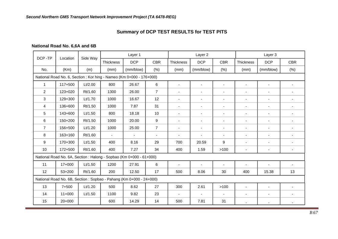
Second Northern GMS Transport Network Improvement Project (TA 6478-REG)
B 67
Summary of DCP TEST RESULTS for TEST PITS
National Road No. 6,6A and 6B
Layer 1 Layer 2 Layer 3 DCP -TP Location Side Way
Thickness DCP CBR Thickness DCP CBR Thickness DCP CBR
No. (Km) (m) (mm) (mm/blow) (%) (mm) (mm/blow) (%) (mm) (mm/blow) (%)
National Road No. 6, Section : Kor hing - Nameo (Km 0+000 - 176+000)
1 117+500 Lt/2.00 800 26.67 6 - - - - - -
2 123+020 Rt/1.60 1300 26.00 7 - - - - - -
3 129+300 Lt/1.70 1000 16.67 12 - - - - - -
4 136+600 Rt/1.50 1000 7.87 31 - - - - - -
5 143+600 Lt/1.50 800 18.18 10 - - - - - -
6 150+200 Rt/1.50 1000 20.00 9 - - - - - -
7 156+500 Lt/1.20 1000 25.00 7 - - - - - -
8 163+160 Rt/1.60 - - - - - - - - -
9 170+300 Lt/1.50 400 8.16 29 700 20.59 9 - - -
10 172+500 Rt/1.60 400 7.27 34 400 1.59 >100 - - -
National Road No. 6A, Section : Halong - Sopbao (Km 0+000 - 61+000)
11 17+000 Lt/1.50 1200 27.91 6 - - - - - -
12 53+200 Rt/1.60 200 12.50 17 500 8.06 30 400 15.38 13
National Road No. 6B, Section : Sopbao - Pahang (Km 0+000 - 24+000)
13 7+500 Lt/1.20 500 8.62 27 300 2.61 >100 - - -
14 11+000 Lt/1.50 1100 9.82 23 - - - - - -
15 20+000 600 14.29 14 500 7.81 31 - - -
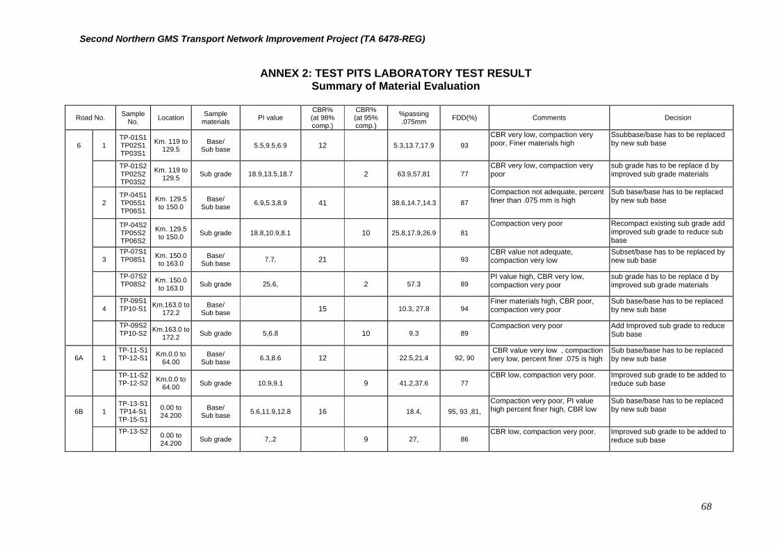
Second Northern GMS Transport Network Improvement Project (TA 6478-REG)
68
ANNEX 2: TEST PITS LABORATORY TEST RESULT Summary of Material Evaluation
Road No. Sample
No. Location Sample materials PI value
CBR% (at 98% comp.)
CBR% (at 95% comp.)
%passing .075mm FDD(%) Comments Decision
6 1 TP-01S1TP02S1TP03S1
Km. 119 to 129.5
Base/ Sub base 5.5,9.5,6.9 12 5.3,13.7,17.9 93
CBR very low, compaction very poor, Finer materials high
Ssubbase/base has to be replaced by new sub base
TP-01S2TP02S2TP03S2
Km. 119 to 129.5 Sub grade 18.9,13.5,18.7 2 63.9,57,81 77
CBR very low, compaction very poor
sub grade has to be replace d by improved sub grade materials
2 TP-04S1TP05S1TP06S1
Km. 129.5 to 150.0
Base/ Sub base 6.9,5.3,8.9 41 38.6,14.7,14.3 87
Compaction not adequate, percent finer than .075 mm is high
Sub base/base has to be replaced by new sub base
TP-04S2TP05S2TP06S2
Km. 129.5 to 150.0 Sub grade 18.8,10.9,8.1 10 25.8,17.9,26.9 81
Compaction very poor Recompact existing sub grade add improved sub grade to reduce sub base
3 TP-07S1TP08S1
Km. 150.0 to 163.0
Base/ Sub base 7.7, 21 93
CBR value not adequate, compaction very low
Subset/base has to be replaced by new sub base
TP-07S2TP08S2
Km. 150.0 to 163.0 Sub grade 25.6, 2 57.3 89
PI value high, CBR very low, compaction very poor
sub grade has to be replace d by improved sub grade materials
4 TP-09S1TP10-S1
Km.163.0 to 172.2
Base/ Sub base 15 10.3, 27.8 94
Finer materials high, CBR poor, compaction very poor
Sub base/base has to be replaced by new sub base
TP-09S2TP10-S2
Km.163.0 to 172.2 Sub grade 5,6.8 10 9.3 89
Compaction very poor Add Improved sub grade to reduce Sub base
6A 1 TP-11-S1TP-12-S1
Km.0.0 to 64.00
Base/ Sub base 6.3,8.6 12 22.5,21.4 92, 90
CBR value very low , compaction very low, percent finer .075 is high
Sub base/base has to be replaced by new sub base
TP-11-S2TP-12-S2
Km.0.0 to 64.00 Sub grade 10.9,9.1 9 41.2,37.6 77
CBR low, compaction very poor. Improved sub grade to be added to reduce sub base
6B 1 TP-13-S1TP14-S1TP-15-S1
0.00 to 24.200
Base/ Sub base 5.6,11.9,12.8 16 18.4, 95, 93 ,81,
Compaction very poor, PI value high percent finer high, CBR low
Sub base/base has to be replaced by new sub base
TP-13-S2
0.00 to 24.200 Sub grade 7,.2 9 27, 86
CBR low, compaction very poor. Improved sub grade to be added to reduce sub base

Second Northern GMS Transport Network Improvement Project (TA 6478-REG)
69
Annex F of Part B Institutional Issues - Lao PDR
A/F 1 Introduction 365. While the primary thrust of the Project is to upgrade the main road and important connecting roads in the corridor, the benefits from this intervention will not be sustained unless adequate provisions are in place to maintain the roads after construction.
366. In Lao PDR the Ministry of Public Works and Transport (MPWT) has overall responsibility for about 38,000 km of roads and direct responsibility for about 7250 kilometers of national highways. Provincial DPWT located in each province are responsible for provincial, district, urban and rural roads. DPWT report to the MPWT on national road and technical matters and to the Provincial Governor on provincial road matters. Provincial DPWT appear to have a limited say in the identification of works prior to budget approval. The works are largely identified by a Road Management System (RMS) using data that is presently not always accurate nor is it necessarily current9.
367. Road maintenance is undertaken by contractors, most of whom are private sector. Maintenance activities are largely restricted to the 2800 km of roads that are new or in good or in good condition10. Elsewhere the maintenance work is minimal, often limited to works required to keep a road open to traffic.
368. The World Bank is providing assistance with the restructuring of Lao MPWT, including identification of human resource requirements and capacity strengthening under an organizational capacity development component of RMPII. The Bank’s consultant has developed a comprehensive approach across the MPWT. This report does not address MPWT institutional issues that have already been covered by RMPII.
A/F 2 Problem Identification 369. There is a problem in Lao PDR Nam with roads being not maintained or inadequately maintained. As with road authorities the world over, the primary reason given is lack of money and resources. However this may not be the whole answer. Investigation by the Consultant has found a number of factors that are contributing to the problem:
• Construction and maintenance work of poor quality leading to premature failure;
• Decisions made centrally based on inadequate or outdated data;
• Lack of appropriate equipment (eg graders for gravel roads)
370. The Government Lao PDR appears to recognize that there is an issue. With encouragement from the IFI, performance based contracting – which (in theory) places greater day-to-day responsibility in the hands of the contractor, had been adopted for contracts (covering approximately 2800 km of National Roads) in Lao PDR. The form of PBC introduced in Lao PDR is, however, more property described as a ‘output orientated schedule of rates contract’ than a true PBC. The contract periods are relatively short, the work to be done is specified by the DPWT and do not include periodic or emergency
9 This was found to be the case on the project roads in Lao PDR. 10 Approximately 2800 km by December 2008. Contracts were a mixture of PBC (requirements not tough and also not always enforced) and schedule of rates. Funding allocations for 2 sections of road R6 in Houaphan were USD 1400 and 2000 per kilometer per year for routine and emergency (small scale) maintenance work

Second Northern GMS Transport Network Improvement Project (TA 6478-REG)
70
maintenance. The primary responsibility for management of the asset therefore remains with the DPWT. Lao has nevertheless moved much further down the privatization path than Viet Nam.
A/F 3 PERFORMANCE BASED CONTRACTING
A/F 3.1 Concerns with PBC 371. There is never perceived to be enough money for road maintenance: everywhere in the world road agencies struggle with less money than they think should be spent. This means that when it comes to setting up long term contracts – ie contracts covering more than a year and therefore more than one budget cycle, the total payments committed under the contracts can become an issue.
372. Other concerns raised include that the Project would be ICB and international bidders would not be interested in the maintenance component because the contract size is too small, while local companies have no relevant experience. Rates are expected to be far too high because bidders will internalize the risk – in particular if there are concerns about future payment they will ensure that their costs are returned in the first few years. There is a belief that the concept has failed elsewhere.
373. The solution most likely to address the various concerns and to achieve the potential of PBC is to encourage a joint venture approach between local and international companies. The international company would mobilize resources for the construction period and provide technological support for the local company over the contract duration. While this would not be attractive to some overseas companies who would prefer to come, build and move on, it would suit an international company that has/wants a long term presence in the country. In any case it will be necessary to have large enough areas under contract so that there is a ‘critical mass’ of work to interest the international company.
374. It may be possible for the invitation to tender to offer a choice of conventional or PBC to enable the government to chose based on the bids received. This will force bidders to make their PBC bids competitive with a conventional approach.
375. The concept of a Build and Operate PBC (or contract with extended maintenance period) has been proposed before. One problem is that ADB loan funding is not normally available for maintenance. This is because ADB does not want loan money to be used for ‘consumption’ so there is nothing to show for the loan when it is due to be repaid. However when it is generally recognized that lack of maintenance is a major problem, it may be better to address this issue directly rather than attempt to ensure roads are maintained through the use of covenants.
376. ADB (or other donors) could assist in ensuring that PBC was successful by making some of the loan payable monthly (or as appropriate) during the maintenance period on evidence of payment to the contractor by the government. If the donor’s involvement with a country was a ‘one off’ it might be desirable for all the funding to be made available over a limited period. However for an agency like ADB that has a long term presence, an extended loan period should not create a problem.
A/F 4 Funding
A/F 4.1 General 377. Maintenance of National roads in Lao PDR are funded through the Road Maintenance Fund which receives funds from 3 sources. Funding is however not adequate and needs to be supported from external sources, even for the National Road

Second Northern GMS Transport Network Improvement Project (TA 6478-REG)
71
Network. Lesser roads and minor highways are reported to receive little to no funds which means that they can become impassible during the wet season. This could change from 2010/11 with a significant share of the revenue from the NT-2 hydro power project being allocated for transport access improvements in poor rural areas.
A/F 4.2 The Issue 378. Funding is central to private participation in road maintenance. Commitment from the private sector will be hard to obtain unless there are reasonable long term prospects – this requires some certainty of funding. Lack of certainty increases risks. With public sector operators this risk manifests itself in higher than needed workforces and inefficient use of resources. With private sector operators it is reflected in high contract prices and unwillingness to bid.
379. There is no point in setting up contracts with insufficient money. This is true both for the individual contracts and for the sector as a whole. It might be argued that if the budget is not sufficient to provide for periodic maintenance, the contracts should cover routine maintenance only and that when periodic maintenance is required it would have to be prioritized against other roads. This would be a mistake.
380. It is not possible to save money by optimizing only part of the system. If the contractor has responsibility for routine maintenance but not for periodic maintenance, he has no interest in optimizing total expenditure. He will argue for more periodic maintenance than is optimal since this will reduce the routine maintenance cost. And if the periodic maintenance is not done, he will argue that this is a breach of contract since more routine maintenance is now required than allowed for in the contract.
381. If there really is insufficient money for periodic maintenance to maintain the roads in good condition, then overall funding priorities need to be sorted out before anything else. The question that needs to be asked is “which roads will be allowed to deteriorate?” At least for some roads, maintenance standards will have to fall so as to fit the budget constraint. If this is politically unacceptable, the only solution is to increase the maintenance budget. Any other action (such as cutting back on periodic maintenance) will make matters worse, not better.
A/F 4.3 Tolls 382. Bundling the revenue source with the construction and maintenance project, as is the case with BOT toll roads, can provide a way of providing a long term contract in circumstances where the government would be unwilling to commit to a long term maintenance only contract.
383. Tolls provide the most obvious and straight forward form of user charge. They establish a nexus between road use and payment; and between road use and maintenance expenditure. Tolls can be set to vary by vehicle type, time of day and journey length thus potentially providing economic signals to users. The main disadvantages are high transaction costs and the need (with conventional systems) for exit and entry control. They are seen as an option for major arterial routes such as the ring roads and for bridges, but not for the general road network. Tolls are often associated with private sector investment but can also be used independently as a source of government funds.