technical binder~ v1 - btec.vnbtec.vn/imgupload/futronix/technical binder-010.pdf · systems...
TRANSCRIPT
T E C H N I C A L B I N D E R ~ v1.21

T E C H N I C A L B I N D E R ~ v1.287
T E C H N I C A L B I N D E R ~ v1.21
Cont
ents
CONTENTS
Company ProfileTechnical Cut Sheets
PFX SystemPFS SystemPFR SystemEnvirosceneHome-Icon TouchScreenHx automation controlP800 scene dimmerP400 scene dimmerP100 scene dimmerP50 level dimmerPIR Movement Detector
PFX Detailed SpecificationM & E SpecificationLighting Consultant’s SpecificationLighting Control Systems (example of typical specification)FAQ - Lighting Control Systems
3-1617-2018-2122-2425-2728-3132-3334-3536-3940-4243-4546-4748-4950-6162-6566-7273-7576-86
2

T E C H N I C A L B I N D E R ~ v1.287
T E C H N I C A L B I N D E R ~ v1.23
Com
pany
Pro
file
FUTRONIX
Futronix designs and manufactures the mostcomprehensive range of intelligent lighting andhome automation controllers for commercial andresidential applications.
Building on almost two decades of research anddevelopment, sophisticated design, and advancedmanufacturing skills, Futronix lighting controlsystems convert an ageless necessity – lighting –into an ultramodern customer benefit, providingcomplete and effortless control over lightingenvironments.
Futronix has now become the product of choicefor many leading architects, lighting designersand end-use customers, with major installationsworldwide, annual sales growth exceeding 25%year on year, and a growing reputation as a majorinnovator in the field of all-digital lightingcontrol.
The marketThe market for intelligent lighting controls growsannually. Businesses and homeowners alike areincreasingly accustomed to convenientautomated control of their environments, andwith energy-efficient lighting becoming afinancial necessity, the market is assured ofcontinued rapid growth.
With all products designed and developed in-house, our rapid product development turnaroundallows fast response to feedback from customersand distributors, allowing Futronix to consistentlyanticipate and fulfill market requirements withan unrivalled lineup of versatile dimmers.
Through its’ global network of distributors anddealers, Futronix assists customers at everystage, from specification through commissioningto long-term maintenance programs. Stafftraining, comprehensive information andinstruction manuals, and international qualitysales and marketing materials are readilyavailable to assist dealers in securing luxuryresidential projects, or in answering the manyand complex questions arising during bidding formajor commercial lighting control projects.
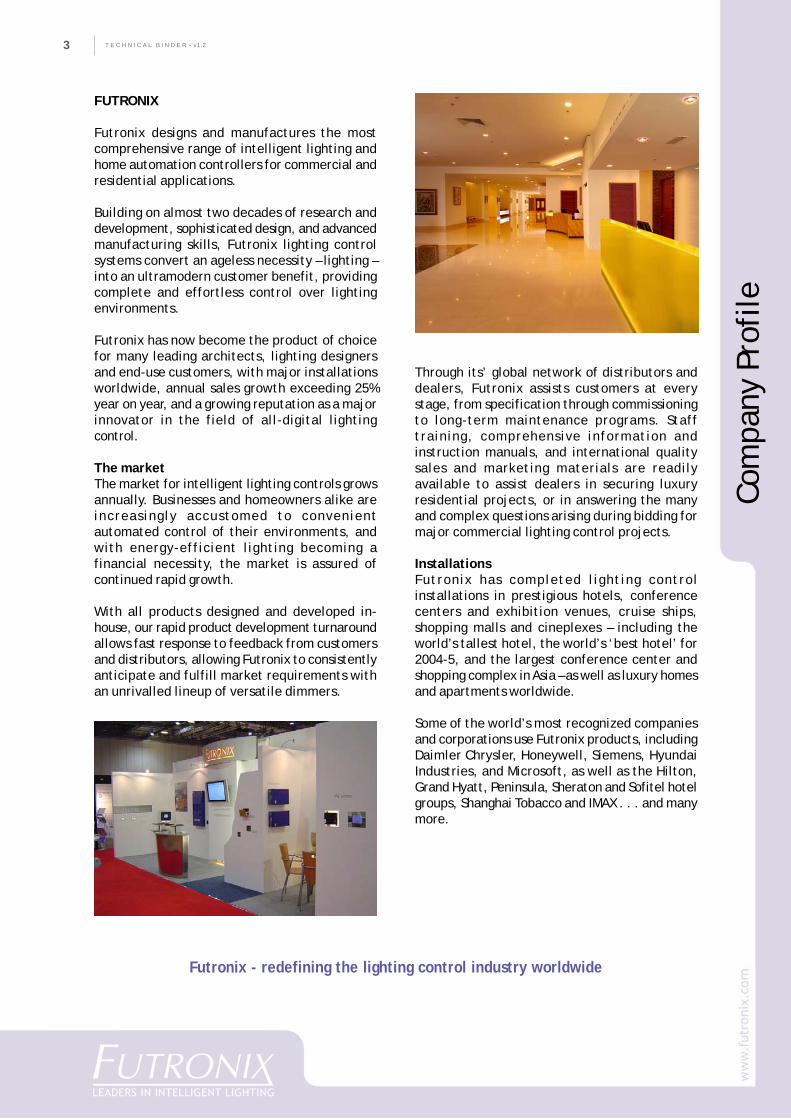
InstallationsFutronix has completed lighting controlinstallations in prestigious hotels, conferencecenters and exhibition venues, cruise ships,shopping malls and cineplexes – including theworld’s tallest hotel, the world’s ‘best hotel’ for2004-5, and the largest conference center andshopping complex in Asia – as well as luxury homesand apartments worldwide.
Some of the world’s most recognized companiesand corporations use Futronix products, includingDaimler Chrysler, Honeywell, Siemens, HyundaiIndustries, and Microsoft, as well as the Hilton,Grand Hyatt, Peninsula, Sheraton and Sofitel hotelgroups, Shanghai Tobacco and IMAX . . . and manymore.
Futronix - redefining the lighting control industry worldwide
4
CO
MPA
NY
PR
OFI
LET E C H N I C A L B I N D E R ~ v1.2 4
THE FUTRONIX APPROACHFutronix’ success is based on five principles:
quality of products and service above allelsepricing to remain competitivedependability of products, delivery andfield serviceflexibility within a broad product range,customizable products, and fast responsetimeinnovation in products and technology.
We constantly endeavor to incorporate thesebasic principles in further developing ourindustry-leading lighting control products.
Futronix steadily enhances its’ position as aleading international supplier of architecturallighting control systems by:
basing research & development programs oncustomers’ requirements and technicalinnovationsupplying advanced systems that are reliable,easy to install and operate, yet sufficientlyversatile to offer fully-featured controldesigning and manufacturing different butcompatible controller systems for integrationinto complete lighting control ‘solutions’providing for seamless integration with 3rd
party equipment if requiredassisting dealers with marketing materialsand programs, and with expert technicalsupportensuring that the end user receives after-salesand support service that sets standards forothers to follow.
Technical innovationFutronix manufactures the only all-digital rangeof lighting control products and accessories withindustry-leading features and convenience. All-digital dimmers with no analog content aresmaller, more accurate and more reliable – andwith all setting up done in software,commissioning is greatly simplified.
Standardized products as system-buildingunitsCustomer requirements are continually analyzedto identify sought-after product features forincorporation into our comprehensive range ofstandard products and accessories.
Individual units are designed to be easily andseamlessly integrated into complete solutionsfor a wide-ranging variety of lighting control
Com
pany
Pro
file
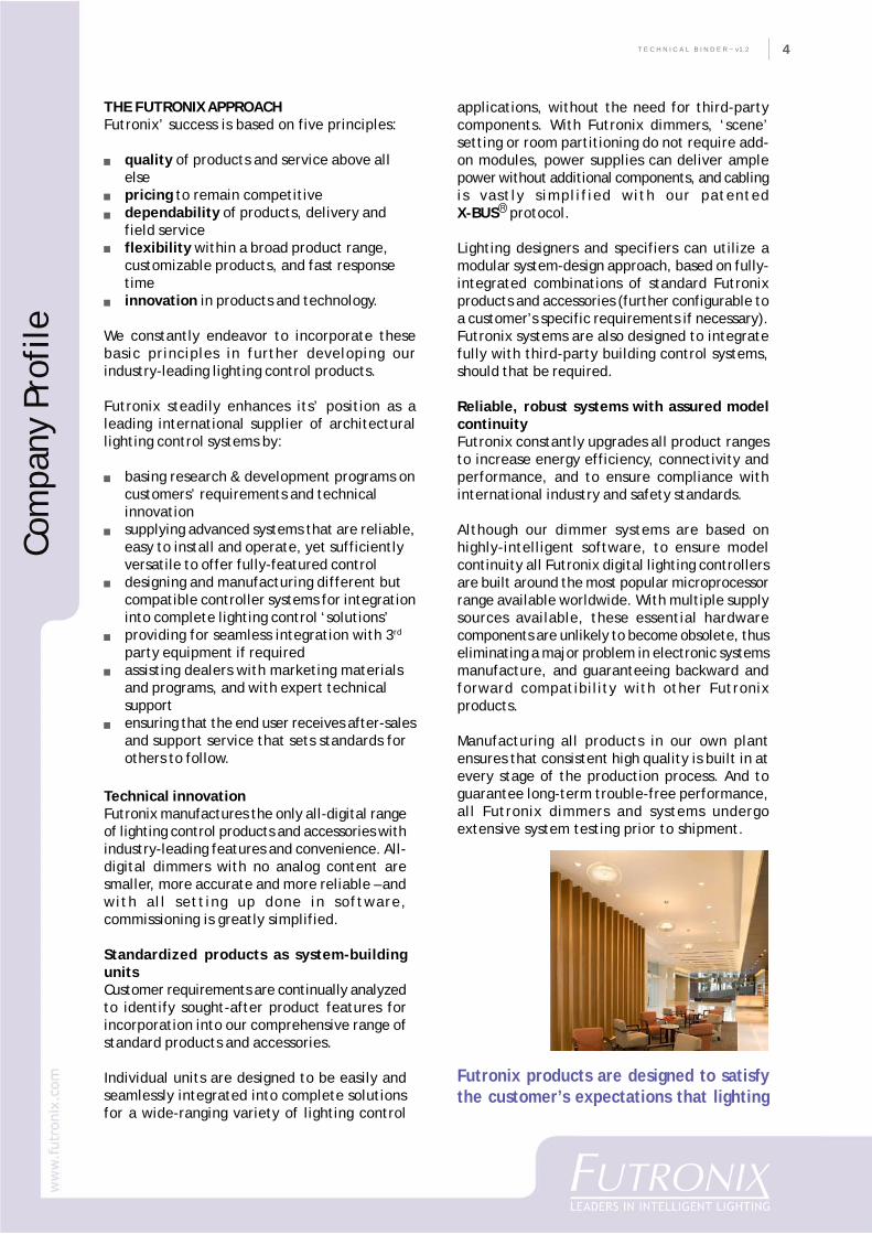
Futronix products are designed to satisfythe customer’s expectations that lighting
applications, without the need for third-partycomponents. With Futronix dimmers, ‘scene’setting or room partitioning do not require add-on modules, power supplies can deliver amplepower without additional components, and cablingis vastly simplified with our patentedX-BUS protocol.
Lighting designers and specifiers can utilize amodular system-design approach, based on fully-integrated combinations of standard Futronixproducts and accessories (further configurable toa customer’s specific requirements if necessary).Futronix systems are also designed to integratefully with third-party building control systems,should that be required.
Reliable, robust systems with assured modelcontinuityFutronix constantly upgrades all product rangesto increase energy efficiency, connectivity andperformance, and to ensure compliance withinternational industry and safety standards.
Although our dimmer systems are based onhighly-intelligent software, to ensure modelcontinuity all Futronix digital lighting controllersare built around the most popular microprocessorrange available worldwide. With multiple supplysources available, these essential hardwarecomponents are unlikely to become obsolete, thuseliminating a major problem in electronic systemsmanufacture, and guaranteeing backward andforward compatibility with other Futronixproducts.
Manufacturing all products in our own plantensures that consistent high quality is built in atevery stage of the production process. And toguarantee long-term trouble-free performance,all Futronix dimmers and systems undergoextensive system testing prior to shipment.
R
T E C H N I C A L B I N D E R ~ v1.25
HISTORY
Throughout our years of innovation, Futronix has constantly led the industry in introduction of productsbased on original design concepts and advanced technologies, resulting in a range of products preferred bylighting designers and architects.
A list of the more important of these innovative products includes:
PRODUCT DEVELOPMENT
Futronix introduced analog scene dimming systemPF16 digital 16-channel scene dimmerPC link and timer for PF16PFS commercial scene dimmer systemPF4 – first low-cost residential scene dimmer systemP400 introduced – the world’s smallest residential scene dimmerPFX commercial digital scene dimmer, feature–rich specification, multi-zone,3-phase, mains compensationEnviroscene light commercial scene dimmer & P400 Classic introducedP100 – first & only available single-switch size scene dimmerP800 – 8-channel, multi-zone residential scene dimmer systemP50 drop-in replacement 3-level dimmer, with no neutralHome-Icon residential automation system introducedIGBT digital sine wave dimmer to dim specialist lampsPFX System 2nd generation commercial scene dimmer takes digital scene dimming to a new levelof flexibilityVersion of Windows software adapted for programming and operation, accessories for PFX &Home-Icon systemHome-Icon Color Touch-Screen Control introduced for easy setup and programming of PFX &Enviroscene systemsSystem upgrades for: Commercial – PFX, PFR, PFS Systems; Light commercial – Enviroscene,Home-Icon; Residential – P800, P400; Remote handsets; Switchplate technology – flush-mountedscrewless switchplates using composite technologyHx remote-location residential/light commercial scene dimmers for homes, hospitality, hospitals,offices, etcEclipse glass/stainless screwless flush-mounted ultra-thin switchplates
YEAR
1989199219931994
19951996
1997199819992000200120022003
2004
2005
2006
2007
2007
Com
pany
Pro
file
6
CO
MPA
NY
PR
OFI
LET E C H N I C A L B I N D E R ~ v1.2 6
PROJECTS & APPLICATIONS
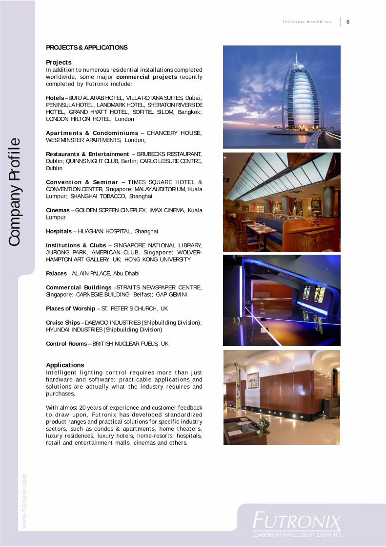
ProjectsIn addition to numerous residential installations completedworldwide, some major commercial projects recentlycompleted by Futronix include:
Hotels – BURJ AL ARAB HOTEL, VILLA ROTANA SUITES, Dubai;PENINSULA HOTEL, LANDMARK HOTEL, SHERATON RIVERSIDEHOTEL, GRAND HYATT HOTEL, SOFITEL SILOM, Bangkok;LONDON HILTON HOTEL, London
Apartments & Condominiums – CHANCERY HOUSE,WESTMINSTER APARTMENTS, London;
Restaurants & Entertainment – BRUBECKS RESTAURANT,Dublin; QUINNS NIGHT CLUB, Berlin; CARLO LEISURE CENTRE,Dublin
Convention & Seminar – TIMES SQUARE HOTEL &CONVENTION CENTER, Singapore; MALAY AUDITORIUM, KualaLumpur; SHANGHAI TOBACCO, Shanghai
Cinemas – GOLDEN SCREEN CINEPLEX, IMAX CINEMA, KualaLumpur
Hospitals – HUASHAN HOSPITAL, Shanghai
Institutions & Clubs – SINGAPORE NATIONAL LIBRARY,JURONG PARK, AMERICAN CLUB, Singapore; WOLVER-HAMPTON ART GALLERY, UK; HONG KONG UNIVERSITY
Palaces – AL AIN PALACE, Abu Dhabi
Commercial Buildings –STRAITS NEWSPAPER CENTRE,Singapore; CARNEGIE BUILDING, Belfast; GAP GEMINI
Places of Worship – ST. PETER’S CHURCH, UK
Cruise Ships – DAEWOO INDUSTRIES (Shipbuilding Division);HYUNDAI INDUSTRIES (Shipbuilding Division)
Control Rooms – BRITISH NUCLEAR FUELS, UK
ApplicationsIntelligent lighting control requires more than justhardware and software; practicable applications andsolutions are actually what the industry requires andpurchases.
With almost 20 years of experience and customer feedbackto draw upon, Futronix has developed standardizedproduct ranges and practical solutions for specific industrysectors, such as condos & apartments, home theaters,luxury residences, luxury hotels, home-resorts, hospitals,retail and entertainment malls, cinemas and others.
Com
pany
Pro
file
T E C H N I C A L B I N D E R ~ v1.27
Apartments & Condominiums
Developers of apartment and condominium projectscan add ‘smart home’ value to their properties –without the complication and expense ofcentralized systems – by using stand-aloneresidential dimmers.
With multiple units in each development, just onedimmer installed in each unit can result in asubstantial project, typically with standardizedinstallation throughout.
Property developers in particular appreciate thebenefits of installing ‘fit-&-forget’ stand-alonedimmers such as the P400 or P800 scene dimmers inapartment or condominium units, where operationalreliability, avoidance of any single-point-of-failure,ease of maintenance and superb product supportare essential requirements for any lighting controlsystem installed.
Developers favor dimmers that are easy to install,cable and connect, and simple to program, witheasily programmable switchplates. And if repairs areneeded, dimmers must be able to be easily removedand re-fitted by any competent electrician.
Stand-alone scene dimmers such as the FutronixHx can be installed in a concealed location in anapartment or condominium unit to orchestrate thelighting in just one room or a suite of rooms, or tocontrol lighting in a bedroom, kitchen or bathroom.
For energy efficiency and customer service in rentalapartments and all-suite apartments, Hx dimmerscan be linked to a reception controller at eachfloor lobby.
All P400, P800 and Hx dimmers feature an in-builtX-Bus databus, allowing easy connection to otherFutronix dimmers and accessories if required.
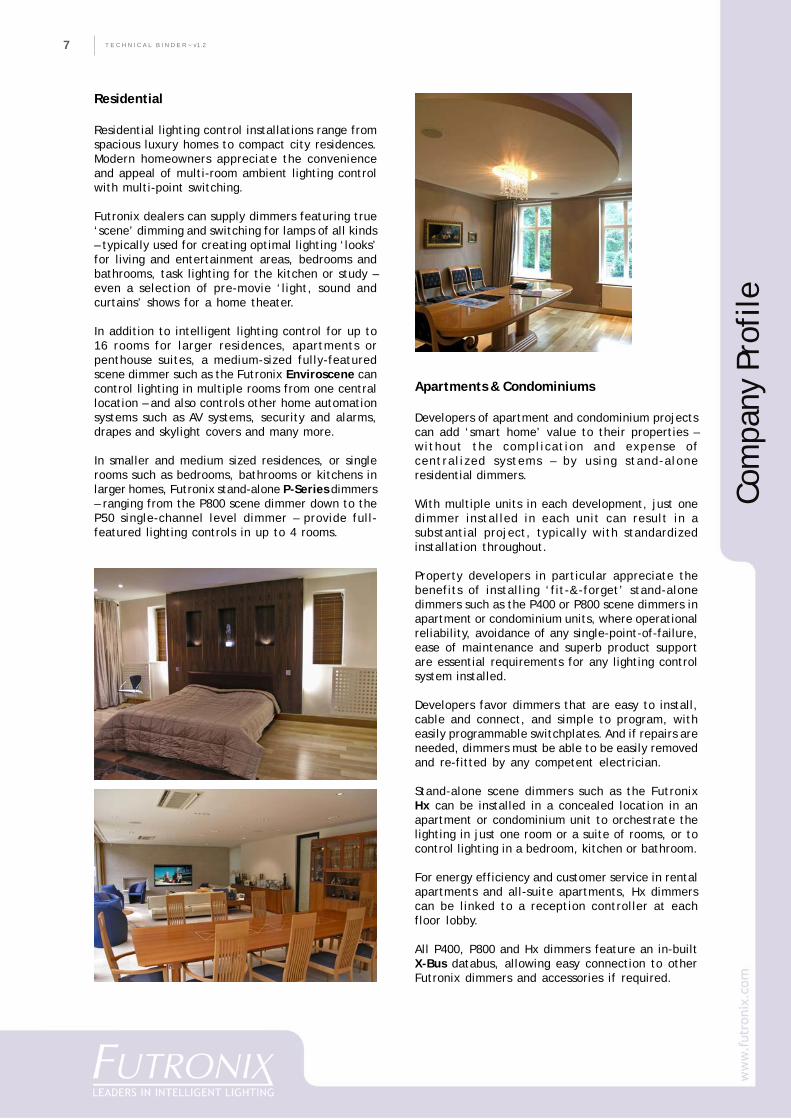
Residential
Residential lighting control installations range fromspacious luxury homes to compact city residences.Modern homeowners appreciate the convenienceand appeal of multi-room ambient lighting controlwith multi-point switching.
Futronix dealers can supply dimmers featuring true‘scene’ dimming and switching for lamps of all kinds– typically used for creating optimal lighting ‘looks’for living and entertainment areas, bedrooms andbathrooms, task lighting for the kitchen or study –even a selection of pre-movie ‘light, sound andcurtains’ shows for a home theater.
In addition to intelligent lighting control for up to16 rooms for larger residences, apartments orpenthouse suites, a medium-sized fully-featuredscene dimmer such as the Futronix Enviroscene cancontrol lighting in multiple rooms from one centrallocation – and also controls other home automationsystems such as AV systems, security and alarms,drapes and skylight covers and many more.
In smaller and medium sized residences, or singlerooms such as bedrooms, bathrooms or kitchens inlarger homes, Futronix stand-alone P-Series dimmers– ranging from the P800 scene dimmer down to theP50 single-channel level dimmer – provide full-featured lighting controls in up to 4 rooms.
Com
pany
Pro
file
8
CO
MPA
NY
PR
OFI
LET E C H N I C A L B I N D E R ~ v1.2 8
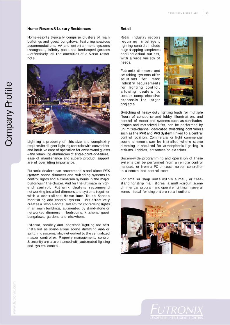
Home-Resorts & Luxury Residences
Home-resorts typically comprise clusters of mainbuildings and guest bungalows, featuring spaciousaccommodations, AV and entertainment systemsthroughout, infinity pools and landscaped gardens– effectively, all the amenities of a 5-star resorthotel.
Lighting a property of this size and complexityrequires intelligent lighting controls with convenientand intuitive ease of operation for owners and guests– and reliability, elimination of single-point-of-failure,ease of maintenance and superb product supportare of overriding importance.
Futronix dealers can recommend stand-alone PFXSystem scene dimmers and switching systems tocontrol lights and automation systems in the majorbuildings in the cluster. And for the ultimate in high-end control, Futronix dealers recommendnetworking installed dimmers and systems togetherwith a centralized Home-Icon Touch Screenmonitoring and control system. This effectivelycreates a ‘whole-home’ system for controlling lightsin all main buildings, augmented by stand-alone ornetworked dimmers in bedrooms, kitchens, guestbungalows, gardens and elsewhere.
Exterior, security and landscape lighting are bestinstalled as stand-alone scene dimming and/orswitching systems, also networked to the centralizedmaster controller. Property management, control& security are also enhanced with automated lightingand system control.
Retail
Retail industry sectorsrequiring intelligentlighting controls includehuge shopping complexesand individual outlets,with a wide variety ofneeds.
Futronix dimmers andswitching systems offersolutions for mostindustry requirementsfor lighting control,allowing dealers totender comprehensiveproposals for largerprojects.
Switching of heavy duty lighting loads for multiplefloors of concourse and lobby illumination, andcontrol of motorized systems such as sunshades,drapes and motorized lifts, can be performed byunlimited-channel dedicated switching controllerssuch as the PFR and PFS System linked to a centralcontrol location. Commercial or light commercialscene dimmers can be installed where scenedimming is required for atmospheric lighting inatriums, lobbies, entrances or exteriors.
System-wide programming and operation of thesesystems can be performed from a remote controlhandset, or from a PC or touch-screen controllerin a centralized control room.
For smaller shop units within a mall, or free-standing/strip mall stores, a multi-circuit scenedimmer can program and operate lighting in severalzones – ideal for single-store retail outlets.
Com
pany
Pro
file
T E C H N I C A L B I N D E R ~ v1.29
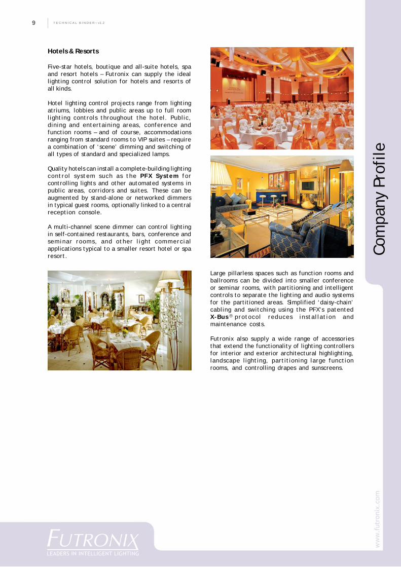
Hotels & Resorts
Five-star hotels, boutique and all-suite hotels, spaand resort hotels – Futronix can supply the ideallighting control solution for hotels and resorts ofall kinds.
Hotel lighting control projects range from lightingatriums, lobbies and public areas up to full roomlighting controls throughout the hotel. Public,dining and entertaining areas, conference andfunction rooms – and of course, accommodationsranging from standard rooms to VIP suites – requirea combination of ‘scene’ dimming and switching ofall types of standard and specialized lamps.
Quality hotels can install a complete-building lightingcontrol system such as the PFX System forcontrolling lights and other automated systems inpublic areas, corridors and suites. These can beaugmented by stand-alone or networked dimmersin typical guest rooms, optionally linked to a centralreception console.
A multi-channel scene dimmer can control lightingin self-contained restaurants, bars, conference andseminar rooms, and other light commercialapplications typical to a smaller resort hotel or sparesort.
Large pillarless spaces such as function rooms andballrooms can be divided into smaller conferenceor seminar rooms, with partitioning and intelligentcontrols to separate the lighting and audio systemsfor the partitioned areas. Simplified ‘daisy-chain’cabling and switching using the PFX’s patentedX-Bus....protocol reduces installation andmaintenance costs.
Futronix also supply a wide range of accessoriesthat extend the functionality of lighting controllersfor interior and exterior architectural highlighting,landscape lighting, partitioning large functionrooms, and controlling drapes and sunscreens.
R
Com
pany
Pro
file

10
CO
MPA
NY
PR
OFI
LET E C H N I C A L B I N D E R ~ v1.2 10
Com
pany
Pro
file
Cinemas
The modern cinema industry is evolving into chainsof cineplexes, with some stand-alone theatersremaining in city centers. Intelligent lightingcontrols for cinemas includes lobby and auditoriumlighting, wall-sconces, seat-row illumination andpossibly integration of motorized systems.
The Futronix PFX System offers sophisticatedlighting control for high-end retail and cinemaprojects, while the Futronix Enviroscene multi-zonesystem is both compact and affordable.
Futronix systems can easily integrate with standardcinema-automation technology, whereby a signalstripe on the film stock triggers relays in theprojector, which then trigger lighting sequencesautomatically. This allows just one projectionist torun up to a dozen films sequentially on separatescreens with staggered starting times.
All cinemas require sound systems and motorizedelements such as curtains, which can also beintegrated to Futronix lighting control systems invarious configurations to provide seamless control.
Hospitals & Health Care Facilities
Hospitals require fail-safe 24/7 lighting throughoutthe facility. Futronix recommend installation ofstand-alone switching racks such as the PFR Systemfor heavy-duty lighting loads for lobbies, corridorsand wards, and for exterior and security lighting,optionally networked to a centralized controllocation.
PFX System dimmers can provide ‘scene’ dimmingfor reception areas if required. Major lightingcontrol systems for an entire facility can becontrolled from a single master control room usinga PC or touch screen graphic interface.
These systems can be augmented by compact multi-channel dimmers in patient rooms and elsewhere,which can be stand-alone or networked to areception controller located at each ward’s nurses’station. Lighting for lecture theaters, auditoriums,cafeterias, restaurants and other discrete areas canbe controlled with a dedicated light commercialmulti-channel scene dimmer.
Commercial
Commercial complexes typically require switchingof heavy-duty loads in corridors, lobbies and publicareas. Powerful PFR arc-free switching racks arerecommended for this, with single-point-of-failurerisk minimized with stand-alone installations floor-by-floor, linked to PC or a touch screen controllerin a central location.
A commercial scene dimmer can provide unlimited-channel commercial quality scene dimming whererequired. Hx scene dimmers concealed in theoverhead are the optimum solution for open-planoffices where a centralized system with discretelighting control over individual work areas isrequired.
T E C H N I C A L B I N D E R ~ v1.211
Whatever the application, intelligent lightingcontrollers from Futronix offer unrivalledfeatures, reliability and customer support.
Other applications
Futronix intelligent lighting controllers find countless applications outside the mainstream of architecturallighting. Over the years, we have supplied lighting controllers for cruise liners, mega-yachts, nuclearpower station control rooms, and many others.
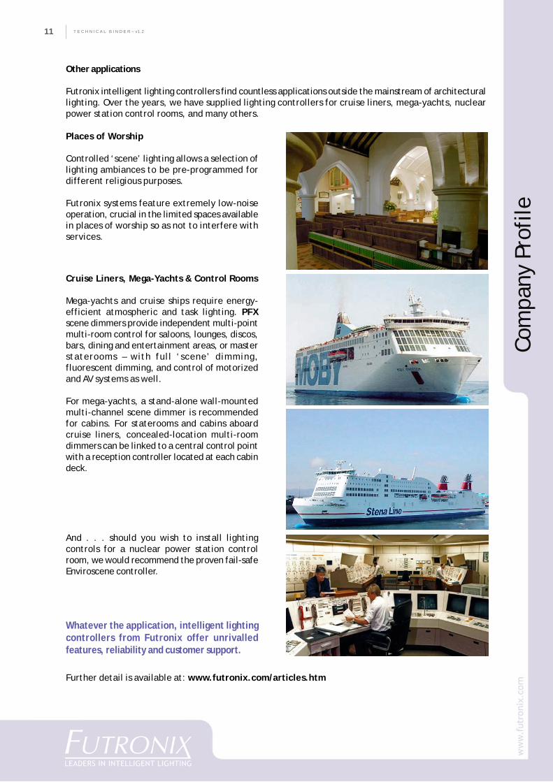
Places of Worship
Controlled ‘scene’ lighting allows a selection oflighting ambiances to be pre-programmed fordifferent religious purposes.
Futronix systems feature extremely low-noiseoperation, crucial in the limited spaces availablein places of worship so as not to interfere withservices.
Further detail is available at: www.futronix.com/articles.htm
Cruise Liners, Mega-Yachts & Control Rooms
Mega-yachts and cruise ships require energy-efficient atmospheric and task lighting. PFXscene dimmers provide independent multi-pointmulti-room control for saloons, lounges, discos,bars, dining and entertainment areas, or masterstaterooms – with full ‘scene’ dimming,fluorescent dimming, and control of motorizedand AV systems as well.
For mega-yachts, a stand-alone wall-mountedmulti-channel scene dimmer is recommendedfor cabins. For staterooms and cabins aboardcruise liners, concealed-location multi-roomdimmers can be linked to a central control pointwith a reception controller located at each cabindeck.
Com
pany
Pro
file
And . . . should you wish to install lightingcontrols for a nuclear power station controlroom, we would recommend the proven fail-safeEnviroscene controller.
12
CO
MPA
NY
PR
OFI
LET E C H N I C A L B I N D E R ~ v1.2 12
PRODUCTS
The Futronix Range of Lighting Control Systems& Dimmers
Futronix lighting controllers afford effortlessmulti-point multi-room control over whole areasof a home or building, and provide end users withconvenient, sophisticated control over theirlighting and environment via simpleuser-friendly interfaces.
All Futronix products – from a singlecircuit dimmer to the most complexlighting control system – are designedto be easy to install and program.Standard-sized or supplied purpose-built wall-boxes and chassis simplify installation, whileadvanced modular designs and connectivity allowseamless creation of fully-integrated largesystems.
Commissioning is easily accomplished viaswitchplate, remote control unit or PC, ordedicated touch-screen controller, while intuitiveoperational logic allows scene re-programmingfrom the remote control handset. Pre-programmed ‘keystroke templates’ facilitatecommissioning and setup, allowing installers toset any switchplate to a selected control modewithout having to program every key/functioncommand for every switchplate installed.
PFX System Scene Dimmer[unlimited-channel scenedimmer]
The all-digital PFX System fromFutronix is the most powerful andadvanced commercial ‘scene’dimming system available.
The PFX System creates pleasantand energy-efficient lightingenvironments for such diverse
high-end applications as exclusive hotels,commercial buildings, airports, conventioncenters, cinemas, places of worship, restaurants,cruise ships, control rooms, broadcast studios,and others.
PFX Systems offer reliable, accurate, and quietmanagement of lighting usage with extendedfunctionality, and can interface readily withalarm, security and building automation systems.
Installations of unlimited size and complexity areeasy to specify, install and commission, andsimple to maintain in operation, with PFX modularsystem architecture built around a range ofstandard-sized chassis, each with its’ ownintelligence.
Switching controls for motorized equipment
Motorized equipment and components integratedinto a building-automation system require acontroller with output that can mimic a switch-press requiring a pulse contact closure of variableduration.
PFS System [unlimited-channel motorizedequipment switching unit]
The PFS switching unit can operate virtually anymotor-driven equipment or device, includingskylights, drapes and curtains, TV lifts, screens,pool covers and others.
The PFS System features inputs and outputs easilyconfigurable according to required function,adjustable voltage level triggering for switchingfluorescent ballasts, and can also operate low-level control loads such as intruder/fire alarmsand AV equipment.
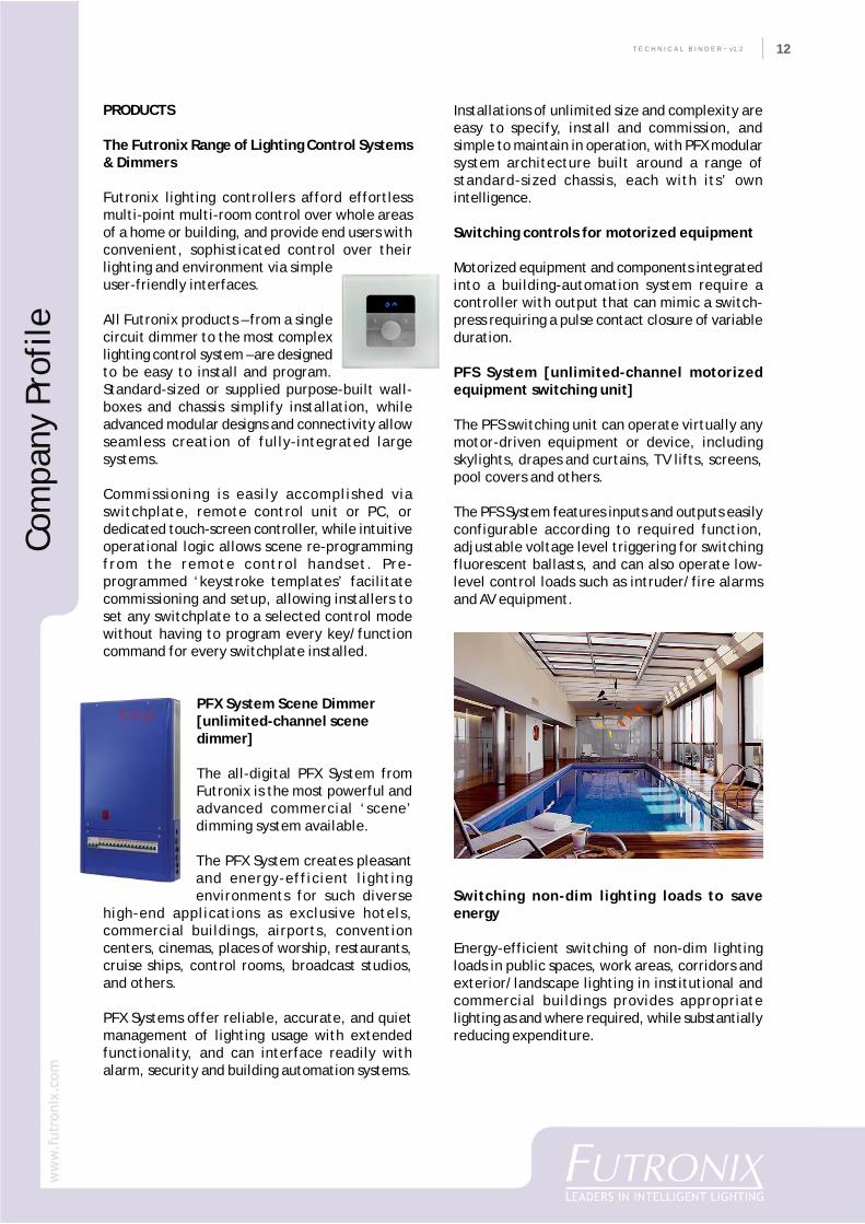
Switching non-dim lighting loads to saveenergy
Energy-efficient switching of non-dim lightingloads in public spaces, work areas, corridors andexterior/landscape lighting in institutional andcommercial buildings provides appropriatelighting as and where required, while substantiallyreducing expenditure.
Com
pany
Pro
file
T E C H N I C A L B I N D E R ~ v1.213
PFR System [unlimited-channelswitching rack]
The PFR System is a chassis-mounted relay switching panel,primarily intended for high-poweredswitching of non-dim lighting loadstypical to large-scale buildingsrequiring extensive area or external
security lighting.
Available in 8 up to 16-channel formats, the PFR’sarc-free relay technology provides extendedoperational life.
Enviroscene [16-room scene dimmer]
Designed for fully-featured intelligent lightingcontrol for luxury residential or light commercialinstallations (bars, restaurants, cinemas), theEnviroscene multi-channel dimmer – installed ina concealed location – is simple to cable and setup.
An affordable intelligent dimming system capableof controlling multiple zones in largerinstallations, the Enviroscene is built around arange of standard modules, and is easilyprogrammed and operated via remote control
handset, laptop or PCcomputer, or the FutronixHome-Icon TFT Color TouchScreen Controller.
The Enviroscene can alsocontrol programmable
automation features such ascurtains and drapes, and AV equipment – andinterfaces with security and alarm systems.
And the compact, versatile Enviroscene operateseconomically, with unused lighting energy savedthrough digital dimming.
Hx Dimmers [remote location dimmers]
Unobtrusive yet powerful,Futronix Hx dimmers aredesigned to controllighting for apartments,condos, luxury residences,hotel/resort rooms and guestbungalows, small offices andconference rooms.
R
Com
pany
Pro
file
Installed in an overhead cavity or other concealedelectrical void, Hx units provide one-touch, multi-point control via switchplates or the suppliedremote handset.
The Hx-12 features multi-channel ‘scene’dimming and switching, combined withsophisticated lighting control and networkingoptions typically offered only by much largercentralized dimming systems – and in addition tolighting, the versatile Hx-12 can also controlcurtains and drapes.
Hx-12 dimmers installed as stand-alone units canbe networked together without the expense ofcentralized systems. And for energy-efficientoperation of discrete rooms from a central floor-control, Hx dimmers networked to a FutronixReception Controller allow staff to activate orde-activate room lighting and other systems whenan occupant is checked in or out.
Hx-2 dimmers offer the same remote installationadvantages in a 2-channel dimmer that can simplybe put in position via the existing lamp cut-outin the ceiling.
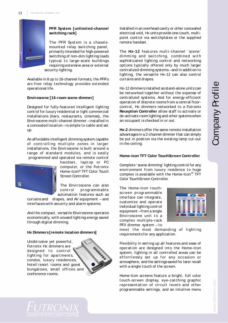
Home-Icon TFT Color TouchScreen Controller
Complete ‘scene dimming’ lighting control for anyenvironment from luxury residence to hugecomplex is available with the Home-Icon TFTColor TouchScreen Controller.
The Home-Icon touch-screen programmableinterface can integrate,customize and operateindividual lighting controlequipment – from a singleEnviroscene unit to acomplex multiple-rackPFX dimmer system – tomeet the most demanding of lightingrequirements for any application.
Flexibility in setting up all features and ease ofoperation are designed into the Home-Iconsystem; lighting in all controlled areas can beeffortlessly set up for any occasion oratmosphere, and the settings saved for later recallwith a single touch of the screen.
Home-Icon screens feature a bright, full colortouch-screen display, eye-catching graphicrepresentation of circuit levels and otherprogrammable settings, and an intuitive menu
R
14
CO
MPA
NY
PR
OFI
LET E C H N I C A L B I N D E R ~ v1.2 14
Switchplates & Remotes
Stylish, robust & timeless, Futronix switchpanelscombine multiplex functionality with simple,minimalist design.
The wide variety of switch-function designs allowsowners to mix & match mastering andfunctionality, as well as finishes. Solid metalfaceplates are available in our standard finishesof brushed or polished stainless steel, polished
brass and white metal – eachindividually hand-finished.
Outstation Switch Platesavailable for Futronix dimmerscan be used as multi-locationswitches to select scenes in anyor all different rooms or areas.
Stunning new ultra-thin Eclipse switchpanels –made of translucent glass and polished stainless– are the first genuinely flush-mounted screwlessremovable switchpanels available – thanks to ourpatented interchangeable locking system basedon advanced composite manufacturing processes.
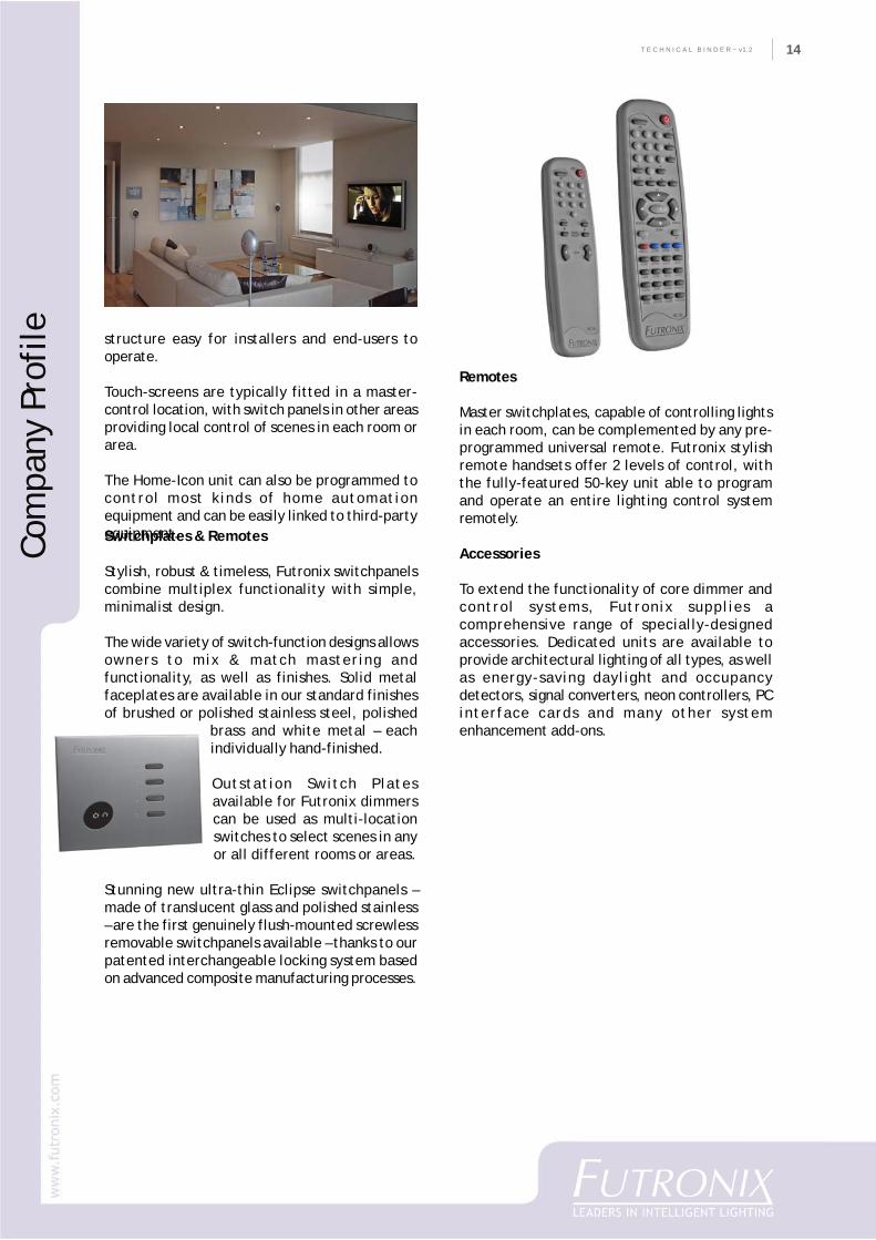
structure easy for installers and end-users tooperate.
Touch-screens are typically fitted in a master-control location, with switch panels in other areasproviding local control of scenes in each room orarea.
The Home-Icon unit can also be programmed tocontrol most kinds of home automationequipment and can be easily linked to third-partyequipment.
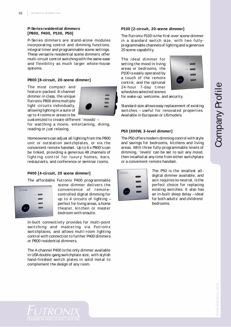
Remotes
Master switchplates, capable of controlling lightsin each room, can be complemented by any pre-programmed universal remote. Futronix stylishremote handsets offer 2 levels of control, withthe fully-featured 50-key unit able to programand operate an entire lighting control systemremotely.
Accessories
To extend the functionality of core dimmer andcontrol systems, Futronix supplies acomprehensive range of specially-designedaccessories. Dedicated units are available toprovide architectural lighting of all types, as wellas energy-saving daylight and occupancydetectors, signal converters, neon controllers, PCinterface cards and many other systemenhancement add-ons.
Com
pany
Pro
file
T E C H N I C A L B I N D E R ~ v1.215
P800 [8-circuit, 20-scene dimmer]
The most compact andfeature-packed 8-channeldimmer in class, the uniqueFutronix P800 dims multiplelight circuits individually,allowing lighting in a suite ofup to 4 rooms or areas to becustomized to create different ‘moods’ –for watching a movie, entertaining, dining,reading or just relaxing.
Homeowners can adjust all lighting from the P800unit or outstation switchplates, or via theconvenient remote handset. Up to 6 x P800’s canbe linked, providing a generous 48 channels oflighting control for luxury homes, bars,restaurants, and conference or seminar rooms.
P400 [4-circuit, 20 scene dimmer]
The affordable Futronix P400 programmablescene dimmer delivers theconvenience of remote-controlled digital dimming forup to 4 circuits of lighting –perfect for living areas, a hometheater, kitchen or masterbedroom with ensuite.
In-built connectivity provides for multi-pointswitching and mastering via Futronixswitchplates, and allows multi-room lightingcontrol with connection to further P400 dimmersor P800 residential dimmers.
The 4-channel P400 is the only dimmer availablein USA double-gang switchplate size, with stylishhand-finished switch plates in solid metal tocomplement the design of any room.
P100 [2-circuit, 20-scene dimmer]
The Futronix P100 is the first-ever scene dimmerin a standard switch size, with two fully-programmable channels of lighting and a generous20 scene capability.
The ideal dimmer forsetting the mood in livingareas or bedrooms, theP100 is easily operated bya touch of the remotecontrol, and the optional24-hour 7-day timerschedules selected scenesfor wake-up, welcome, and security.
Standard-size allows easy replacement of existingswitches – useful for renovated properties.Available in European or US models.
P50 [600W, 3-level dimmer]
The P50 offers modern dimming control with styleand savings for bedrooms, kitchens and livingareas. With three fully-programmable levels ofdimming, ‘levels’ can be set to suit any mood,then recalled at any time from either switchplateor a convenient remote handset.
The P50 is the smallest all-digital dimmer available, andas it requires no neutral, is theperfect choice for replacingexisting switches. It also hasan in-built sleep delay – idealfor both adults’ and childrens’bedrooms.
Com
pany
Pro
file
P-Series residential dimmers[P800, P400, P100, P50]
P-Series dimmers are stand-alone modulesincorporating control and dimming functions,integral timer and programmable scene settings.These versatile residential scene dimmers offermulti-circuit control switching with the same easeand flexibility as much larger whole-housesystems.
16
CO
MPA
NY
PR
OFI
LET E C H N I C A L B I N D E R ~ v1.2 16
FUTRONIX DEALER/INTEGRATORS
Through our network of dealers, Futronix assurescustomers worldwide of expert support andpersonal attention at every stage.
Futronix dealers install, commission and serviceall our lighting control products, supported byfactory engineers with extensive technicalknowledge and wide experience in the lightingcontrol industry. Dealers derive revenue fromsales, installation & commissioning, andmaintenance contracts, and repeat customersfrequently order new or extended systems.Distributing Futronix products also assists ourdealers to on-sell other lighting-related products,systems and services.
We provide our dealers with comprehensive andconstantly updated information, assistance withtechnical enquiries, staff training support – evenperformance evaluation can be undertaken in ourcompany’s Research & Development lab should adealer want to test an alternate ballast, orintegrate a locally-sourced transformer into aFutronix system installation.
Dealers liaise with the customer’s personnel toreview system design prior to ordering;installation and on-site commissioning of systemsis carried out by the dealer’s (or factory) engineer.
Futronix After-Sales Service & MaintenanceContracts for Major Projects
Futronix and our dealers maintain detailedrecords of every quotation and project, enablingus to provide comprehensive after-sales servicefor all installed Futronix systems – either throughour distributors or directly – throughout aninstallation’s lifetime. Additionally, our dealer’sengineers can assist to make changes to a currentsystem or integrate with other systems.
In order to simplify and schedule systemmaintenance, Annual Service Contracts for majorprojects are recommended and available viaDealer/Integrators – a reassuring arrangementfor customers and an additional revenue streamfor dealers. Following handover of an installation,our dealers’ Service Engineers are available forwarranty or non-warranty callouts on a pre-agreedresponse time basis.
FUTRONIX SUPPORT FOR DEALERS
Distributors and dealers in Futronix’ worldwidedistribution network become key strategicpartners in the growth industry of intelligentlighting control, building automation, & energymanagement for commercial and residentialapplications – and raise their own professionalstanding at the same time.
To assist dealers in bidding successfully for majorcontracts, Futronix builds brand recognition viacorporate advertising and editorials in leadinginternational industry publications, onlinemarketing, and through trade shows andparticipation in European Formula 3 motor racing.Comprehensive Futronix manuals and technicalsupport documents (available as print, CD & onlineversions) assist dealers in securing andimplementing major projects in their area.
Futronix subscribes to international constructionproject databases and passes along any leads –as well as those generated by our worldwidedistributor network, website, and marketingprograms – to the appropriate regional distributorto follow up.
Dealer loyalty to the Futronix brand – based onresponsiveness to customer feedback, superbtechnological support and services, andinternational level marketing and sales support –ensures that our network, product reputation, andsales continue to expand steadily.
When bidding on major projects, Futronix’international client references and outstandingreputation for quality and reliability providedealers with a highly-convincing introduction topurchasing departments, consultants, and keydecision makers as a ‘core technology’.
Futronix dealers tendering for major projectsknow that with Futronix lighting control systemsas their key product, their ability to successfullypropose highly-profitable turnkey solutions formajor lighting projects is greatly enhanced.
Further detail is available at:
www.futronix.com/articles.htm
Copyright 2007 Futronix All Rights ReservedC
Com
pany
Pro
file
T E C H N I C A L B I N D E R ~ v1.217
Tech
nica
l Cut
She
ets
Technical Cut Sheets
PFX SystemPFS SystemPFR SystemEnvirosceneHome-Icon TouchScreenHx automation controlP800 scene dimmerP400 scene dimmerP100 scene dimmerP50 level dimmerPIR Movement Detector
18
CO
MPA
NY
PR
OFI
LET E C H N I C A L B I N D E R ~ v1.2 18
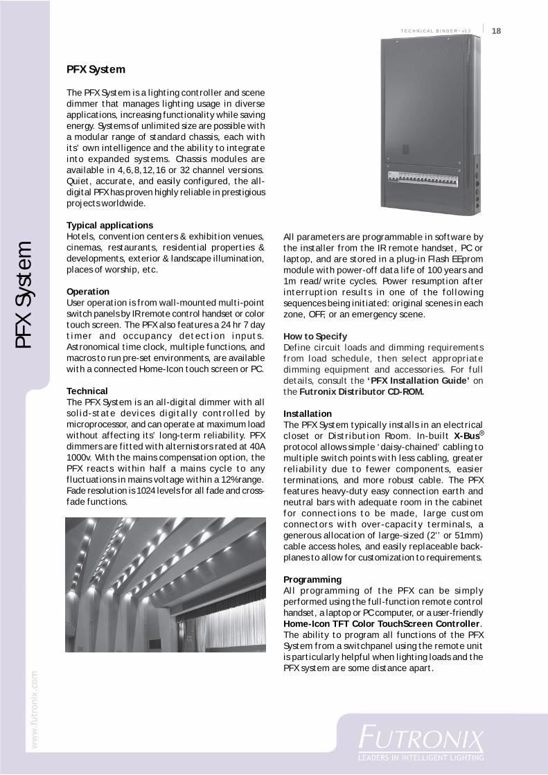
PFX System
The PFX System is a lighting controller and scenedimmer that manages lighting usage in diverseapplications, increasing functionality while savingenergy. Systems of unlimited size are possible witha modular range of standard chassis, each withits’ own intelligence and the ability to integrateinto expanded systems. Chassis modules areavailable in 4,6,8,12,16 or 32 channel versions.Quiet, accurate, and easily configured, the all-digital PFX has proven highly reliable in prestigiousprojects worldwide.
Typical applicationsHotels, convention centers & exhibition venues,cinemas, restaurants, residential properties &developments, exterior & landscape illumination,places of worship, etc.
OperationUser operation is from wall-mounted multi-pointswitch panels by IR remote control handset or colortouch screen. The PFX also features a 24 hr 7 daytimer and occupancy detection inputs.Astronomical time clock, multiple functions, andmacros to run pre-set environments, are availablewith a connected Home-Icon touch screen or PC.
TechnicalThe PFX System is an all-digital dimmer with allsolid-state devices digitally controlled bymicroprocessor, and can operate at maximum loadwithout affecting its’ long-term reliability. PFXdimmers are fitted with alternistors rated at 40A1000v. With the mains compensation option, thePFX reacts within half a mains cycle to anyfluctuations in mains voltage within a 12% range.Fade resolution is 1024 levels for all fade and cross-fade functions.
All parameters are programmable in software bythe installer from the IR remote handset, PC orlaptop, and are stored in a plug-in Flash EEprommodule with power-off data life of 100 years and1m read/write cycles. Power resumption afterinterruption results in one of the followingsequences being initiated: original scenes in eachzone, OFF, or an emergency scene.
How to SpecifyDefine circuit loads and dimming requirementsfrom load schedule, then select appropriatedimming equipment and accessories. For fulldetails, consult the ‘PFX Installation Guide’ onthe Futronix Distributor CD-ROM.
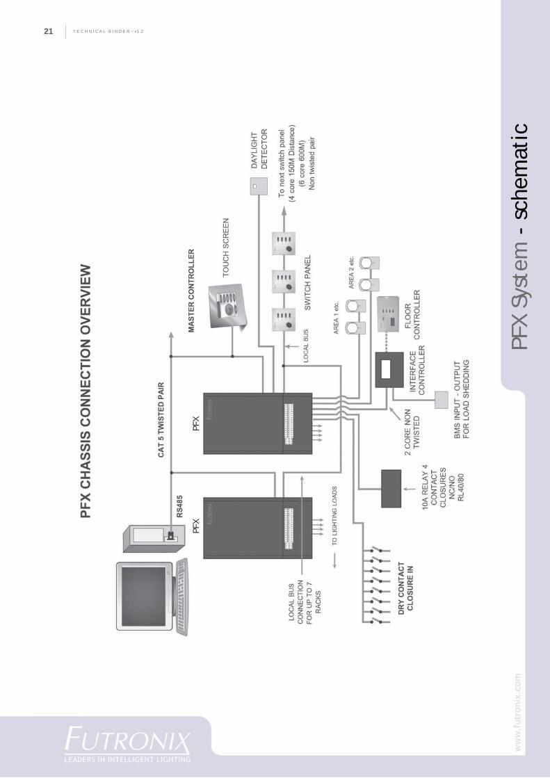
InstallationThe PFX System typically installs in an electricalcloset or Distribution Room. In-built X-Bus�
protocol allows simple ‘daisy-chained’ cabling tomultiple switch points with less cabling, greaterreliability due to fewer components, easierterminations, and more robust cable. The PFXfeatures heavy-duty easy connection earth andneutral bars with adequate room in the cabinetfor connections to be made, large customconnectors with over-capacity terminals, agenerous allocation of large-sized (2’’ or 51mm)cable access holes, and easily replaceable back-planes to allow for customization to requirements.
ProgrammingAll programming of the PFX can be simplyperformed using the full-function remote controlhandset, a laptop or PC computer, or a user-friendlyHome-Icon TFT Color TouchScreen Controller.The ability to program all functions of the PFXSystem from a switchpanel using the remote unitis particularly helpful when lighting loads and thePFX system are some distance apart.
R
PFX
Syst
em
T E C H N I C A L B I N D E R ~ v1.219
PFX
Syst
em -
fea
ture
s
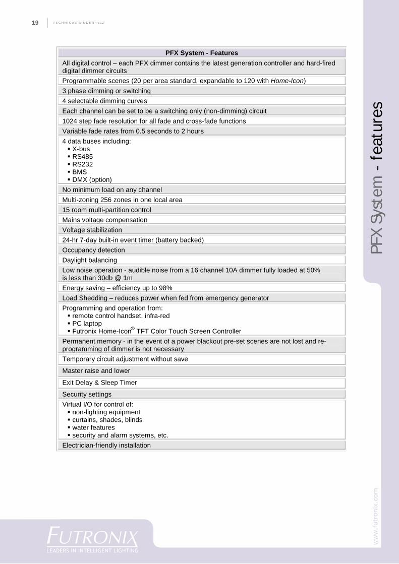
PFX System - Features All digital control – each PFX dimmer contains the latest generation controller and hard-fired digital dimmer circuits Programmable scenes (20 per area standard, expandable to 120 with Home-Icon) 3 phase dimming or switching 4 selectable dimming curves Each channel can be set to be a switching only (non-dimming) circuit 1024 step fade resolution for all fade and cross-fade functions Variable fade rates from 0.5 seconds to 2 hours 4 data buses including:
X-bus RS485 RS232 BMS DMX (option)
No minimum load on any channel Multi-zoning 256 zones in one local area 15 room multi-partition control Mains voltage compensation Voltage stabilization 24-hr 7-day built-in event timer (battery backed) Occupancy detection Daylight balancing Low noise operation - audible noise from a 16 channel 10A dimmer fully loaded at 50% is less than 30db @ 1m Energy saving – efficiency up to 98% Load Shedding – reduces power when fed from emergency generator Programming and operation from:
remote control handset, infra-red PC laptop Futronix Home-Icon® TFT Color Touch Screen Controller
Permanent memory - in the event of a power blackout pre-set scenes are not lost and re-programming of dimmer is not necessary Temporary circuit adjustment without save
Master raise and lower
Exit Delay & Sleep Timer
Security settings Virtual I/O for control of:
non-lighting equipment curtains, shades, blinds water features security and alarm systems, etc.
Electrician-friendly installation
R
20
CO
MPA
NY
PR
OFI
LET E C H N I C A L B I N D E R ~ v1.2 20
PFX
Syst
em -
spe
cifi
cati
ons
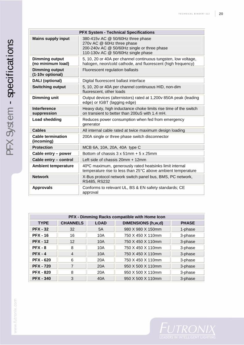
PFX System - Technical Specifications Mains supply input 380-415v AC @ 50/60Hz three phase
270v AC @ 60Hz three phase 200-240v AC @ 50/60Hz single or three phase 110-130v AC @ 50/60Hz single phase
Dimming output (no minimum load)
5, 10, 20 or 40A per channel continuous tungsten, low voltage, halogen, neon/cold cathode, and fluorescent (high frequency)
Dimming output (1-10v optional)
Fluorescent regulation ballasts
DALI (optional) Digital fluorescent ballast interface Switching output 5, 10, 20 or 40A per channel continuous HID, non-dim
fluorescent, other loads Dimming unit Output devices (alternistors) rated at 1,200v 850A peak (leading
edge) or IGBT (lagging edge) Interference suppression
Heavy duty, high inductance choke limits rise time of the switch on transient to better than 200uS with 1.4 mH.
Load shedding Reduces power consumption when fed from emergency generator
Cables All internal cable rated at twice maximum design loading Cable termination (incoming)
200A single or three phase switch disconnector
Protection MCB 6A, 10A, 20A, 40A type C Cable entry – power Bottom of chassis 3 x 51mm + 5 x 25mm Cable entry – control Left side of chassis 20mm + 12mm Ambient temperature 40ºC maximum, generously rated heatsinks limit internal
temperature rise to less than 25°C above ambient temperature
Network X-Bus protocol network switch panel bus, BMS, PC network, RS485, RS232
Approvals Conforms to relevant UL, BS & EN safety standards; CE approval
PFX - Dimming Racks compatible with Home Icon TYPE CHANNELS LOAD DIMENSIONS (h,w,d) PHASE
PFX - 32 32 5A 980 X 980 X 150mm 1-phase PFX - 16 16 10A 750 X 450 X 110mm 3-phase PFX - 12 12 10A 750 X 450 X 110mm 3-phase PFX - 8 8 10A 750 X 450 X 110mm 3-phase PFX - 4 4 10A 750 X 450 X 110mm 3-phase PFX - 620 6 20A 750 X 450 X 110mm 3-phase PFX - 720 7 20A 950 X 500 X 110mm 3-phase PFX - 820 8 20A 950 X 500 X 110mm 3-phase PFX - 340 3 40A 950 X 500 X 110mm 3-phase
T E C H N I C A L B I N D E R ~ v1.221
PFX
Syst
em -
sch
emat
ic
PFX
PFX
22
CO
MPA
NY
PR
OFI
LET E C H N I C A L B I N D E R ~ v1.2 22
PFS
Syst
em
PFS System
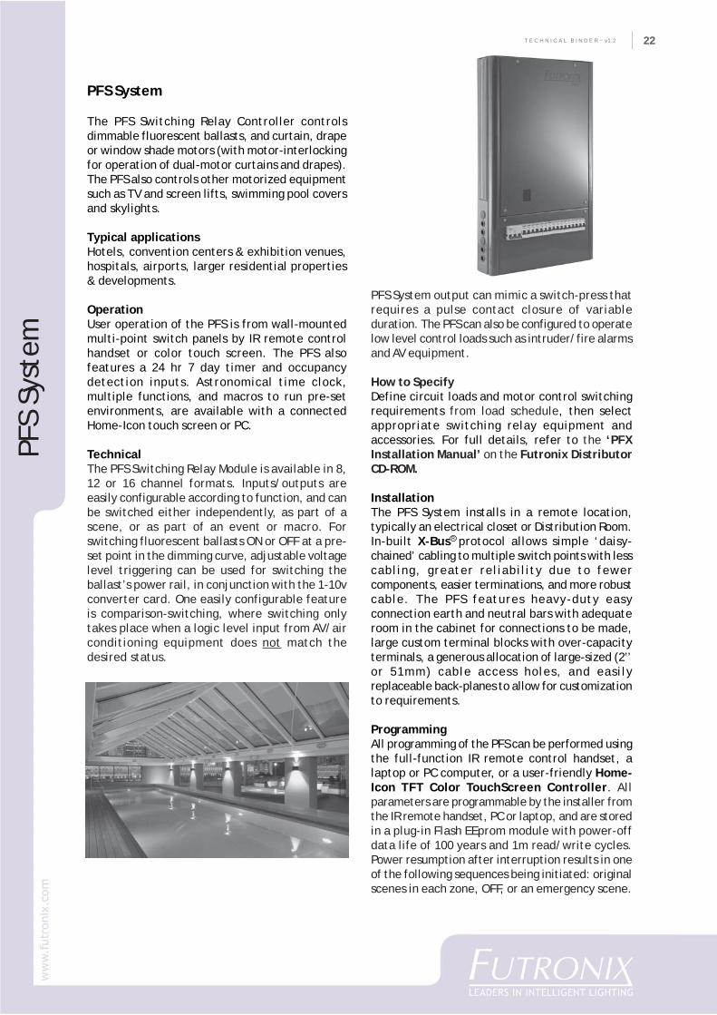
The PFS Switching Relay Controller controlsdimmable fluorescent ballasts, and curtain, drapeor window shade motors (with motor-interlockingfor operation of dual-motor curtains and drapes).The PFS also controls other motorized equipmentsuch as TV and screen lifts, swimming pool coversand skylights.
Typical applicationsHotels, convention centers & exhibition venues,hospitals, airports, larger residential properties& developments.
OperationUser operation of the PFS is from wall-mountedmulti-point switch panels by IR remote controlhandset or color touch screen. The PFS alsofeatures a 24 hr 7 day timer and occupancydetection inputs. Astronomical time clock,multiple functions, and macros to run pre-setenvironments, are available with a connectedHome-Icon touch screen or PC.
TechnicalThe PFS Switching Relay Module is available in 8,12 or 16 channel formats. Inputs/outputs areeasily configurable according to function, and canbe switched either independently, as part of ascene, or as part of an event or macro. Forswitching fluorescent ballasts ON or OFF at a pre-set point in the dimming curve, adjustable voltagelevel triggering can be used for switching theballast’s power rail, in conjunction with the 1-10vconverter card. One easily configurable featureis comparison-switching, where switching onlytakes place when a logic level input from AV/airconditioning equipment does not match thedesired status.
PFS System output can mimic a switch-press thatrequires a pulse contact closure of variableduration. The PFS can also be configured to operatelow level control loads such as intruder/fire alarmsand AV equipment.
How to SpecifyDefine circuit loads and motor control switchingrequirements from load schedule, then selectappropriate switching relay equipment andaccessories. For full details, refer to the ‘PFXInstallation Manual’ on the Futronix DistributorCD-ROM.
InstallationThe PFS System installs in a remote location,typically an electrical closet or Distribution Room.In-built X-Bus� protocol allows simple ‘daisy-chained’ cabling to multiple switch points with lesscabling, greater reliability due to fewercomponents, easier terminations, and more robustcable. The PFS features heavy-duty easyconnection earth and neutral bars with adequateroom in the cabinet for connections to be made,large custom terminal blocks with over-capacityterminals, a generous allocation of large-sized (2’’or 51mm) cable access holes, and easilyreplaceable back-planes to allow for customizationto requirements.
ProgrammingAll programming of the PFS can be performed usingthe full-function IR remote control handset, alaptop or PC computer, or a user-friendly Home-Icon TFT Color TouchScreen Controller. Allparameters are programmable by the installer fromthe IR remote handset, PC or laptop, and are storedin a plug-in Flash EEprom module with power-offdata life of 100 years and 1m read/write cycles.Power resumption after interruption results in oneof the following sequences being initiated: originalscenes in each zone, OFF, or an emergency scene.
R
T E C H N I C A L B I N D E R ~ v1.223
PFS
- fe
atur
es &
spe
cifi
cati
ons
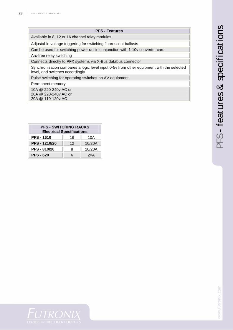
PFS - SWITCHING RACKS Electrical Specifications
PFS - 1610 16 10A PFS - 1210/20 12 10/20A PFS - 810/20 8 10/20A PFS - 620 6 20A
PFS - Features Available in 8, 12 or 16 channel relay modules
Adjustable voltage triggering for switching fluorescent ballasts Can be used for switching power rail in conjunction with 1-10v converter card Arc-free relay switching Connects directly to PFX systems via X-Bus databus connector Synchronisation compares a logic level input 0-5v from other equipment with the selected level, and switches accordingly Pulse switching for operating switches on AV equipment Permanent memory 10A @ 220-240v AC or 20A @ 220-240v AC or 20A @ 110-120v AC
24
CO
MPA
NY
PR
OFI
LET E C H N I C A L B I N D E R ~ v1.2 24
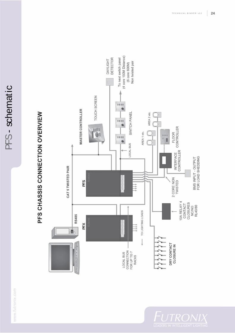
PFS
- sc
hem
atic
PFX
PF
S
T E C H N I C A L B I N D E R ~ v1.225
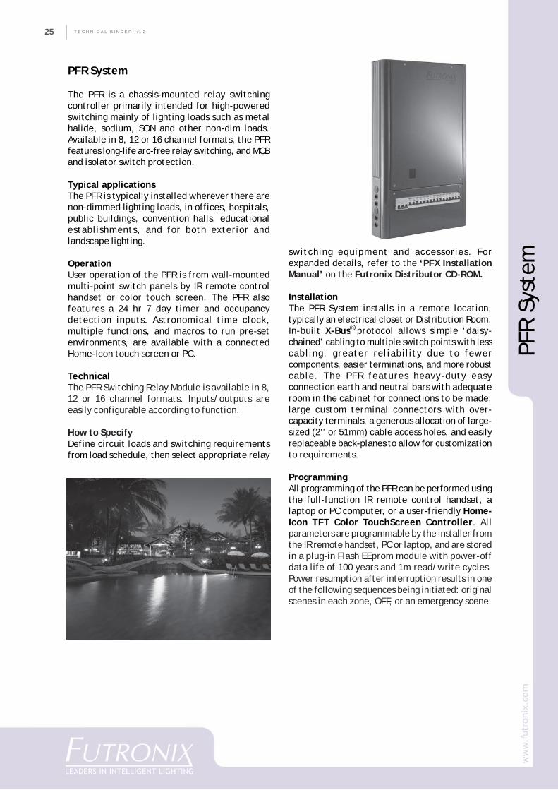
PFR System
The PFR is a chassis-mounted relay switchingcontroller primarily intended for high-poweredswitching mainly of lighting loads such as metalhalide, sodium, SON and other non-dim loads.Available in 8, 12 or 16 channel formats, the PFRfeatures long-life arc-free relay switching, and MCBand isolator switch protection.
Typical applicationsThe PFR is typically installed wherever there arenon-dimmed lighting loads, in offices, hospitals,public buildings, convention halls, educationalestablishments, and for both exterior andlandscape lighting.
OperationUser operation of the PFR is from wall-mountedmulti-point switch panels by IR remote controlhandset or color touch screen. The PFR alsofeatures a 24 hr 7 day timer and occupancydetection inputs. Astronomical time clock,multiple functions, and macros to run pre-setenvironments, are available with a connectedHome-Icon touch screen or PC.
TechnicalThe PFR Switching Relay Module is available in 8,12 or 16 channel formats. Inputs/outputs areeasily configurable according to function.
How to SpecifyDefine circuit loads and switching requirementsfrom load schedule, then select appropriate relay
switching equipment and accessories. Forexpanded details, refer to the ‘PFX InstallationManual’ on the Futronix Distributor CD-ROM.
InstallationThe PFR System installs in a remote location,typically an electrical closet or Distribution Room.In-built X-Bus� protocol allows simple ‘daisy-chained’ cabling to multiple switch points with lesscabling, greater reliability due to fewercomponents, easier terminations, and more robustcable. The PFR features heavy-duty easyconnection earth and neutral bars with adequateroom in the cabinet for connections to be made,large custom terminal connectors with over-capacity terminals, a generous allocation of large-sized (2’’ or 51mm) cable access holes, and easilyreplaceable back-planes to allow for customizationto requirements.
ProgrammingAll programming of the PFR can be performed usingthe full-function IR remote control handset, alaptop or PC computer, or a user-friendly Home-Icon TFT Color TouchScreen Controller. Allparameters are programmable by the installer fromthe IR remote handset, PC or laptop, and are storedin a plug-in Flash EEprom module with power-offdata life of 100 years and 1m read/write cycles.Power resumption after interruption results in oneof the following sequences being initiated: originalscenes in each zone, OFF, or an emergency scene.
PFR
Syst
em
R
26
CO
MPA
NY
PR
OFI
LET E C H N I C A L B I N D E R ~ v1.2 26
PFR
- fe
atur
es &
spe
cifi
cati
ons
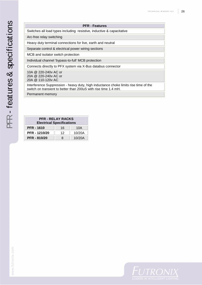
PFR - RELAY RACKS Electrical Specifications
PFR - 1610 16 10A PFR - 1210/20 12 10/20A PFR - 810/20 8 10/20A
PFR - Features Switches all load types including resistive, inductive & capacitative
Arc-free relay switching
Heavy duty terminal connections for live, earth and neutral
Separate control & electrical power wiring sections
MCB and isolator switch protection
Individual channel ‘bypass-to-full’ MCB protection
Connects directly to PFX system via X-Bus databus connector
10A @ 220-240v AC or 20A @ 220-240v AC or 20A @ 110-120v AC Interference Suppression - heavy duty, high inductance choke limits rise time of the switch on transient to better than 200uS with rise time 1.4 mH. Permanent memory
T E C H N I C A L B I N D E R ~ v1.227
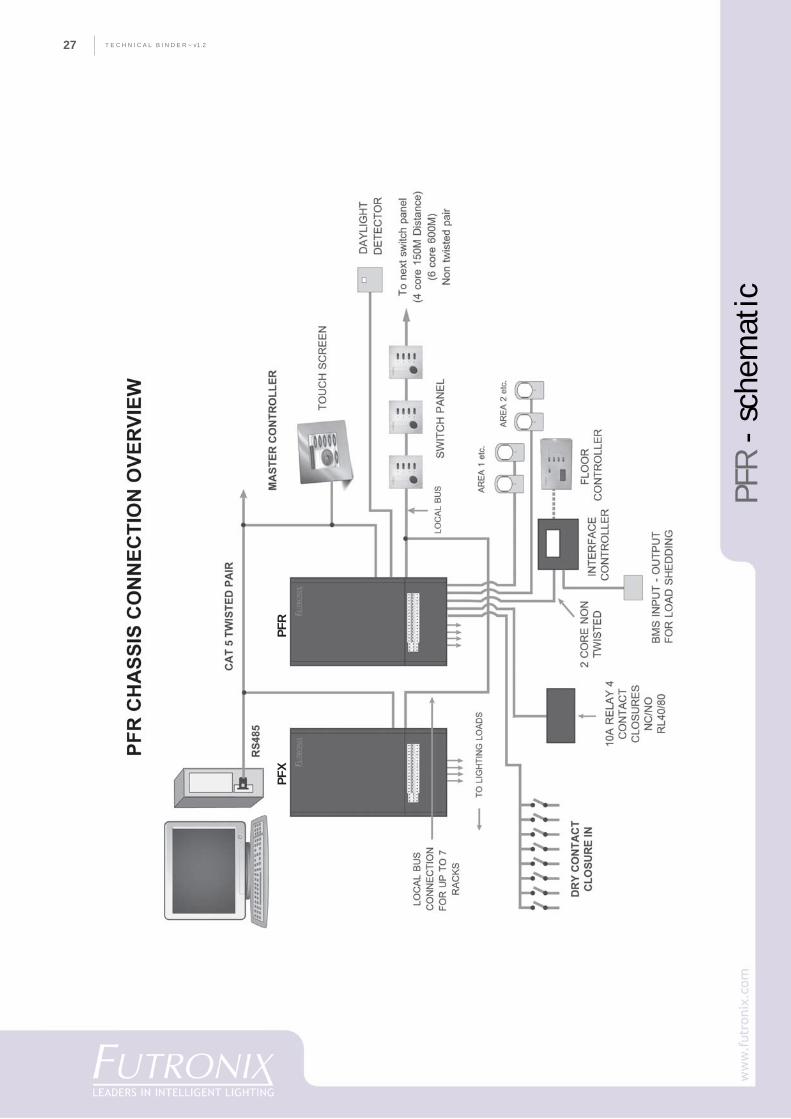
PFR
- sc
hem
atic
PFX
P
FR
28
CO
MPA
NY
PR
OFI
LET E C H N I C A L B I N D E R ~ v1.2 28
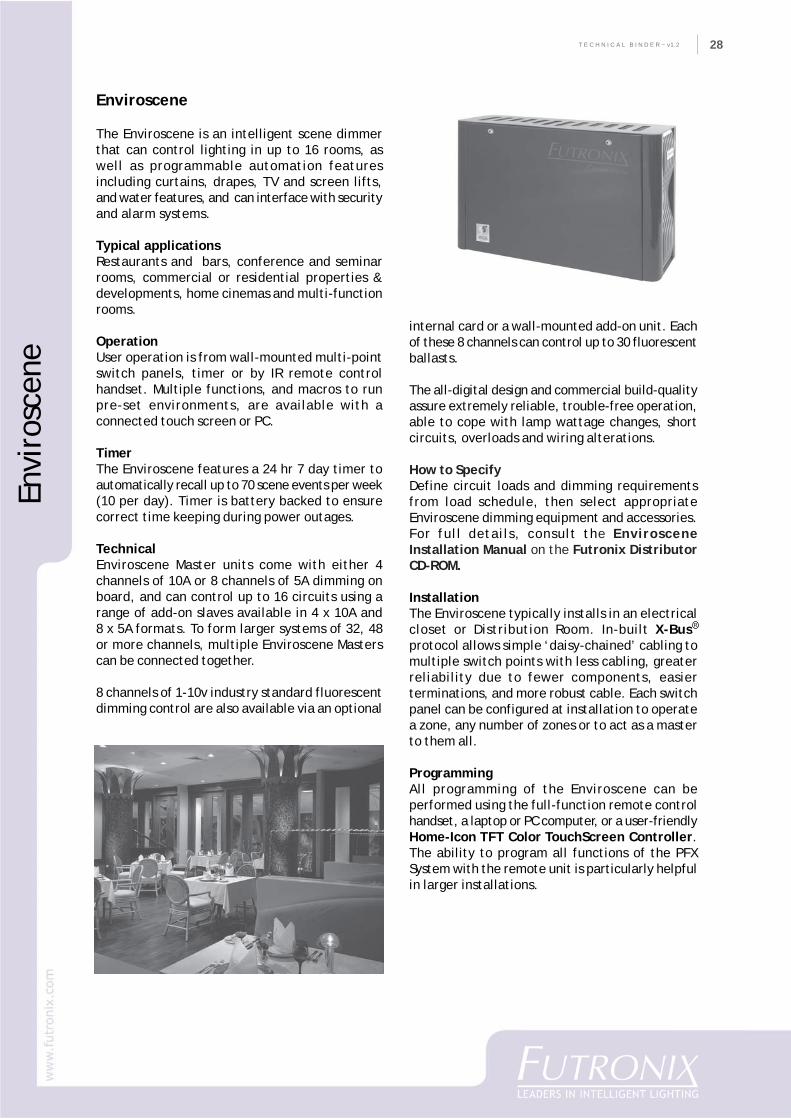
Enviroscene
The Enviroscene is an intelligent scene dimmerthat can control lighting in up to 16 rooms, aswell as programmable automation featuresincluding curtains, drapes, TV and screen lifts,and water features, and can interface with securityand alarm systems.
Typical applicationsRestaurants and bars, conference and seminarrooms, commercial or residential properties &developments, home cinemas and multi-functionrooms.
OperationUser operation is from wall-mounted multi-pointswitch panels, timer or by IR remote controlhandset. Multiple functions, and macros to runpre-set environments, are available with aconnected touch screen or PC.
TimerThe Enviroscene features a 24 hr 7 day timer toautomatically recall up to 70 scene events per week(10 per day). Timer is battery backed to ensurecorrect time keeping during power outages.
TechnicalEnviroscene Master units come with either 4channels of 10A or 8 channels of 5A dimming onboard, and can control up to 16 circuits using arange of add-on slaves available in 4 x 10A and8 x 5A formats. To form larger systems of 32, 48or more channels, multiple Enviroscene Masterscan be connected together.
8 channels of 1-10v industry standard fluorescentdimming control are also available via an optional
internal card or a wall-mounted add-on unit. Eachof these 8 channels can control up to 30 fluorescentballasts.
The all-digital design and commercial build-qualityassure extremely reliable, trouble-free operation,able to cope with lamp wattage changes, shortcircuits, overloads and wiring alterations.
How to SpecifyDefine circuit loads and dimming requirementsfrom load schedule, then select appropriateEnviroscene dimming equipment and accessories.For full details, consult the EnvirosceneInstallation Manual on the Futronix DistributorCD-ROM.
InstallationThe Enviroscene typically installs in an electricalcloset or Distribution Room. In-built X-Bus�
protocol allows simple ‘daisy-chained’ cabling tomultiple switch points with less cabling, greaterreliability due to fewer components, easierterminations, and more robust cable. Each switchpanel can be configured at installation to operatea zone, any number of zones or to act as a masterto them all.
ProgrammingAll programming of the Enviroscene can beperformed using the full-function remote controlhandset, a laptop or PC computer, or a user-friendlyHome-Icon TFT Color TouchScreen Controller.The ability to program all functions of the PFXSystem with the remote unit is particularly helpfulin larger installations.
Envi
rosc
ene
R
T E C H N I C A L B I N D E R ~ v1.229
Envi
rosc
ene
- fe
atur
es
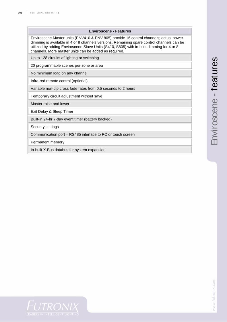
Enviroscene - Features
Enviroscene Master units (ENV410 & ENV 805) provide 16 control channels; actual power dimming is available in 4 or 8 channels versions. Remaining spare control channels can be utilized by adding Enviroscene Slave Units (S410, S805) with in-built dimming for 4 or 8 channels. More master units can be added as required.
Up to 128 circuits of lighting or switching
20 programmable scenes per zone or area
No minimum load on any channel
Infra-red remote control (optional)
Variable non-dip cross fade rates from 0.5 seconds to 2 hours
Temporary circuit adjustment without save
Master raise and lower
Exit Delay & Sleep Timer
Built-in 24-hr 7-day event timer (battery backed)
Security settings
Communication port – RS485 interface to PC or touch screen
Permanent memory
In-built X-Bus databus for system expansion
30
CO
MPA
NY
PR
OFI
LET E C H N I C A L B I N D E R ~ v1.2 30
Envi
rosc
ene
- sp
ecif
icat
ions
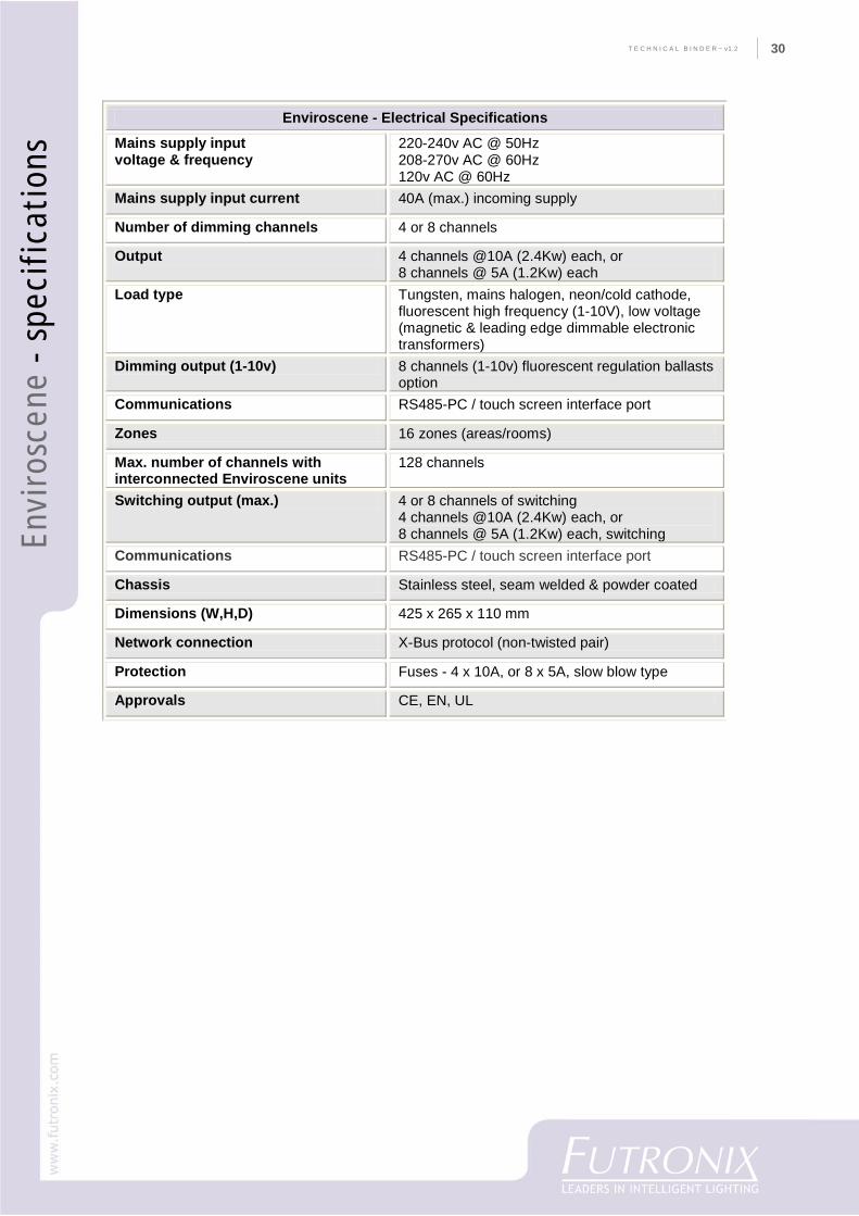
Enviroscene - Electrical Specifications
Mains supply input voltage & frequency
220-240v AC @ 50Hz 208-270v AC @ 60Hz 120v AC @ 60Hz
Mains supply input current 40A (max.) incoming supply
Number of dimming channels 4 or 8 channels
Output 4 channels @10A (2.4Kw) each, or 8 channels @ 5A (1.2Kw) each
Load type Tungsten, mains halogen, neon/cold cathode, fluorescent high frequency (1-10V), low voltage (magnetic & leading edge dimmable electronic transformers)
Dimming output (1-10v) 8 channels (1-10v) fluorescent regulation ballasts option
Communications RS485-PC / touch screen interface port
Zones 16 zones (areas/rooms)
Max. number of channels with interconnected Enviroscene units
128 channels
Switching output (max.) 4 or 8 channels of switching 4 channels @10A (2.4Kw) each, or 8 channels @ 5A (1.2Kw) each, switching
Communications RS485-PC / touch screen interface port
Chassis Stainless steel, seam welded & powder coated
Dimensions (W,H,D) 425 x 265 x 110 mm
Network connection X-Bus protocol (non-twisted pair)
Protection Fuses - 4 x 10A, or 8 x 5A, slow blow type
Approvals CE, EN, UL
T E C H N I C A L B I N D E R ~ v1.231
Envi
rosc
ene
- sc
hem
atic
32
CO
MPA
NY
PR
OFI
LET E C H N I C A L B I N D E R ~ v1.2 32
Hom
e-Ic
on
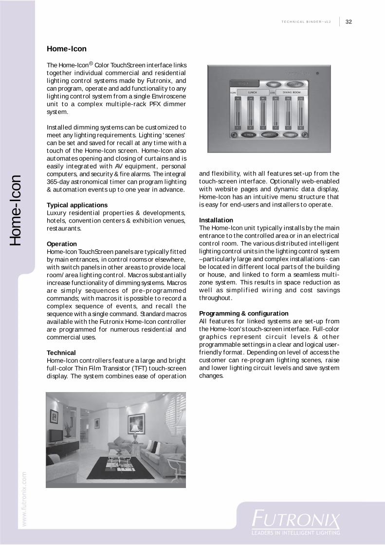
Home-Icon
The Home-Icon� Color TouchScreen interface linkstogether individual commercial and residentiallighting control systems made by Futronix, andcan program, operate and add functionality to anylighting control system from a single Envirosceneunit to a complex multiple-rack PFX dimmersystem.
Installed dimming systems can be customized tomeet any lighting requirements. Lighting ‘scenes’can be set and saved for recall at any time with atouch of the Home-Icon screen. Home-Icon alsoautomates opening and closing of curtains and iseasily integrated with AV equipment, personalcomputers, and security & fire alarms. The integral365-day astronomical timer can program lighting& automation events up to one year in advance.
Typical applicationsLuxury residential properties & developments,hotels, convention centers & exhibition venues,restaurants.
OperationHome-Icon TouchScreen panels are typically fittedby main entrances, in control rooms or elsewhere,with switch panels in other areas to provide localroom/area lighting control. Macros substantiallyincrease functionality of dimming systems. Macrosare simply sequences of pre-programmedcommands; with macros it is possible to record acomplex sequence of events, and recall thesequence with a single command. Standard macrosavailable with the Futronix Home-Icon controllerare programmed for numerous residential andcommercial uses.
TechnicalHome-Icon controllers feature a large and brightfull-color Thin Film Transistor (TFT) touch-screendisplay. The system combines ease of operation
and flexibility, with all features set-up from thetouch-screen interface. Optionally web-enabledwith website pages and dynamic data display,Home-Icon has an intuitive menu structure thatis easy for end-users and installers to operate.
InstallationThe Home-Icon unit typically installs by the mainentrance to the controlled area or in an electricalcontrol room. The various distributed intelligentlighting control units in the lighting control system– particularly large and complex installations - canbe located in different local parts of the buildingor house, and linked to form a seamless multi-zone system. This results in space reduction aswell as simplified wiring and cost savingsthroughout.
Programming & configurationAll features for linked systems are set-up fromthe Home-Icon’s touch-screen interface. Full-colorgraphics represent circuit levels & otherprogrammable settings in a clear and logical user-friendly format. Depending on level of access thecustomer can re-program lighting scenes, raiseand lower lighting circuit levels and save systemchanges.
R
T E C H N I C A L B I N D E R ~ v1.233
Hom
e-Ic
on -
sch
emat
ic
34
CO
MPA
NY
PR
OFI
LET E C H N I C A L B I N D E R ~ v1.2 34
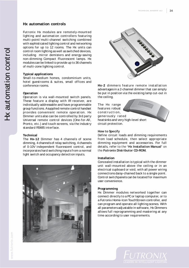
Hx automation controls
Futronix Hx modules are remotely-mountedlighting and automation controllers featuringmulti-point/multi-channel switching combinedwith sophisticated lighting control and networkingoptions for up to 12 rooms. The Hx units cancontrol room lighting as well as switched devices,including mirror demisters and energy-savingnon-dimming Compact Fluorescent lamps. Hxmodules can be linked to provide up to 36 channelsof multi-zone lighting control.
Typical applicationsSmall-to-medium homes, condominium units,hotel guestrooms & suites, small offices andconference rooms.
OperationOperation is via wall-mounted switch panels.These feature a display with IR receiver, areindividually addressable and have programmablegroup functions. A supplied remote control handsetprovides convenient remote operation. HxDimmer units also can be controlled by 3rd partyUniversal remote control devices (One-for-All,Pronto, etc.) and touch screens, via the industrystandard RS485 interface.
TechnicalThe Hx-12 Dimmer has 4 channels of scenedimming, 4 channels of relay switching, 4 channelsof 0-10V independent fluorescent control, andincorporates hard switching inputs from a normallight switch and occupancy detection inputs.
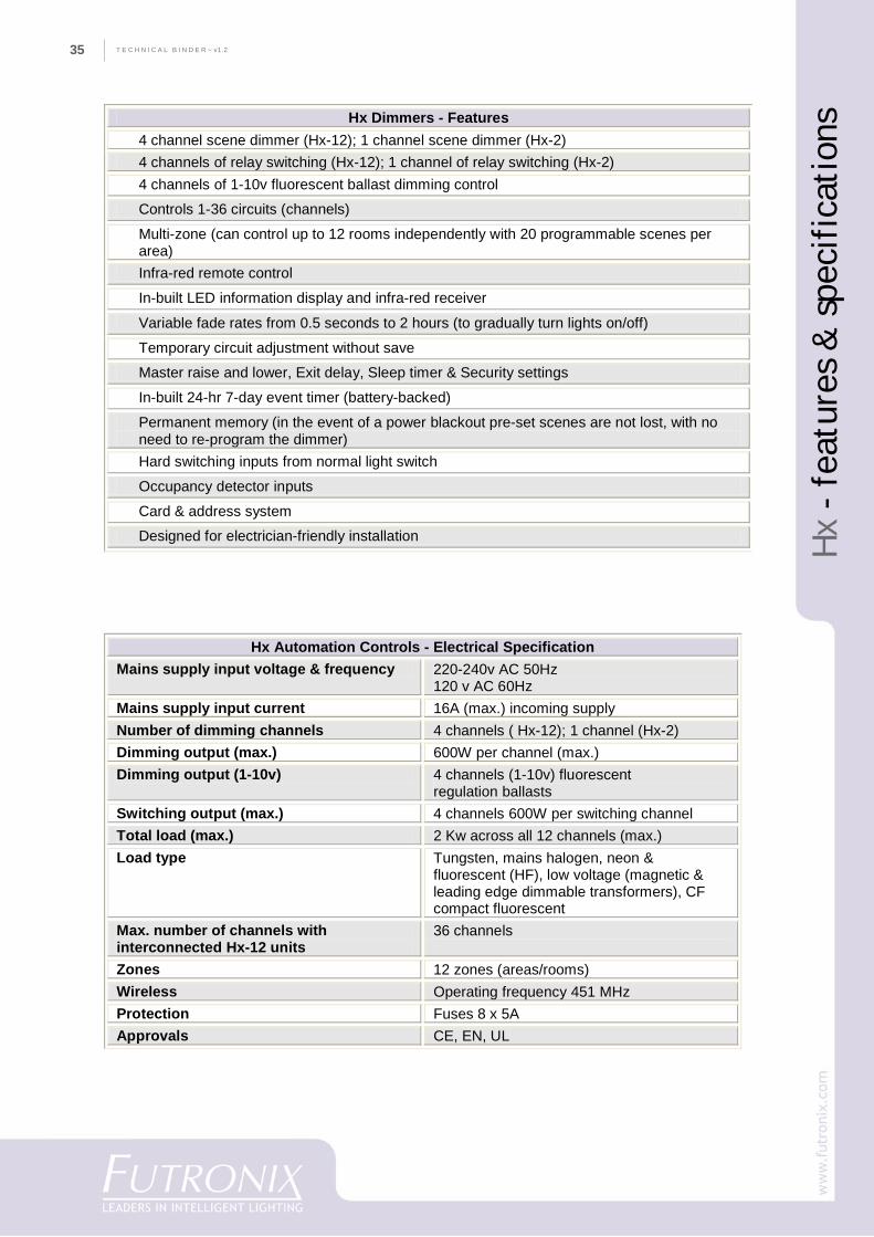
Hx-2 dimmers feature remote installationadvantages in a 2-channel dimmer that can simplybe put in position via the existing lamp cut-out inthe ceiling.
The Hx rangefeatures robustconstruct ion,generously ratedheatsinks and very high-level shortcircuit protection.
How to SpecifyDefine circuit loads and dimming requirementsfrom load schedule, then select appropriatedimming equipment and accessories. For fulldetails, refer to the ‘Hx Installation Manual’ onthe Futronix Distributor CD-ROM.
InstallationConcealed installation is typical with the dimmerunit wall-mounted above the ceiling or in anelectrical cupboard or void, with all power wiringconnections daisy-chained back to a single point.Control switchpanels can be located for maximumuser convenience.
ProgrammingHx Dimmer modules networked together canconnect directly to a PC or laptop computer, or toa Futronix Home-Icon TouchScreen controller, andcan program and operate all lighting scenes. Withall parameters adjustable in software, Hx Dimmersallows full reprogramming and mastering at anytime according to user requirements.
Hx
auto
mat
ion
cont
rol
T E C H N I C A L B I N D E R ~ v1.235
Hx
- fe
atur
es &
spe
cifi
cati
onsHx Dimmers - Features
4 channel scene dimmer (Hx-12); 1 channel scene dimmer (Hx-2) 4 channels of relay switching (Hx-12); 1 channel of relay switching (Hx-2) 4 channels of 1-10v fluorescent ballast dimming control
Controls 1-36 circuits (channels)
Multi-zone (can control up to 12 rooms independently with 20 programmable scenes per area) Infra-red remote control
In-built LED information display and infra-red receiver
Variable fade rates from 0.5 seconds to 2 hours (to gradually turn lights on/off)
Temporary circuit adjustment without save
Master raise and lower, Exit delay, Sleep timer & Security settings
In-built 24-hr 7-day event timer (battery-backed)
Permanent memory (in the event of a power blackout pre-set scenes are not lost, with no need to re-program the dimmer) Hard switching inputs from normal light switch
Occupancy detector inputs
Card & address system
Designed for electrician-friendly installation
Hx Automation Controls - Electrical Specification Mains supply input voltage & frequency 220-240v AC 50Hz
120 v AC 60Hz Mains supply input current 16A (max.) incoming supply Number of dimming channels 4 channels ( Hx-12); 1 channel (Hx-2) Dimming output (max.) 600W per channel (max.) Dimming output (1-10v) 4 channels (1-10v) fluorescent
regulation ballasts Switching output (max.) 4 channels 600W per switching channel Total load (max.) 2 Kw across all 12 channels (max.) Load type Tungsten, mains halogen, neon &
fluorescent (HF), low voltage (magnetic & leading edge dimmable transformers), CF compact fluorescent
Max. number of channels with interconnected Hx-12 units
36 channels
Zones 12 zones (areas/rooms) Wireless Operating frequency 451 MHz Protection Fuses 8 x 5A Approvals CE, EN, UL
36
CO
MPA
NY
PR
OFI
LET E C H N I C A L B I N D E R ~ v1.2 36
TechnicalThe P800 has exceptionally high build quality,robust construction with generously ratedheatsinks and a very high level of short circuitprotection – making the P800 ideal for lightcommercial use.
How to SpecifyDefine circuit loads and dimming requirementsfrom load schedule, then select appropriatedimming equipment and accessories. For fulldetails, consult the ‘P100-P800 InstallationGuide’ on the Futronix Distributor CD-ROM.
Switchpanel finishesP-Series dimmers feature solid 2mm thick metalfaceplates, carefully hand-finished in polished orbrushed stainless, brass or white metal.
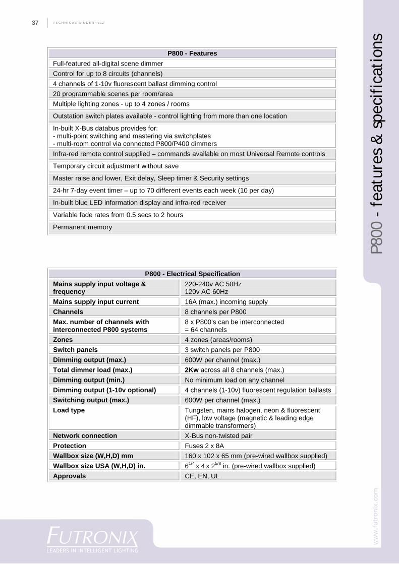
Installation (with supplied wall back-box)The P800 comes with its own pre-wired weldedsteel wall back-box. After wall-finishing the P800is plugged into the back-box connector and screwedinto the back-box. The P800 is approximately 1"(25.4mm) smaller in all dimensions than anycomparable product, with the supplied back-boxmeasuring 102 mm high x 160 mm wide x 65 mmdeep.
ProgrammingAll programming of the P800 can be simplyperformed using the supplied full-function remotecontrol handset or switchplate keys. An in-built24/7 timer provides for programming up to 70scene changes per week.
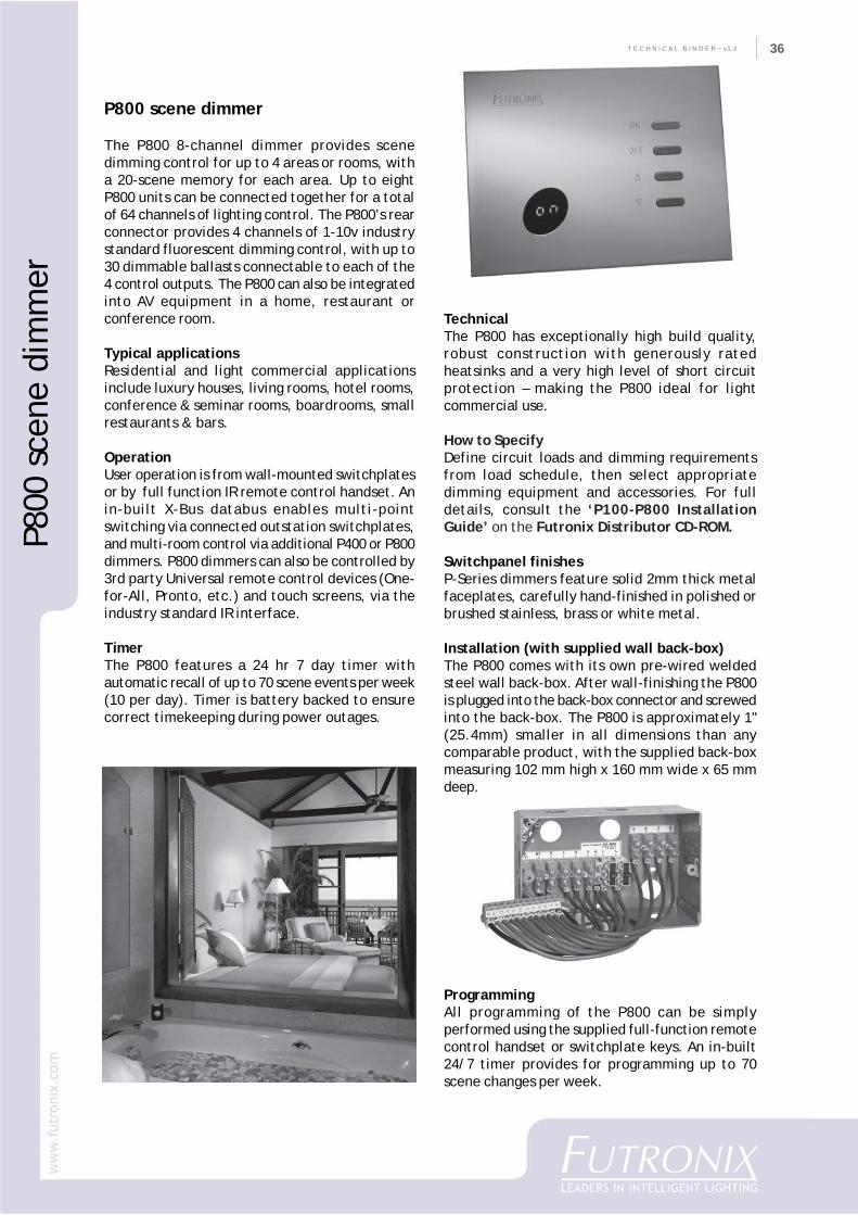
P800 scene dimmer
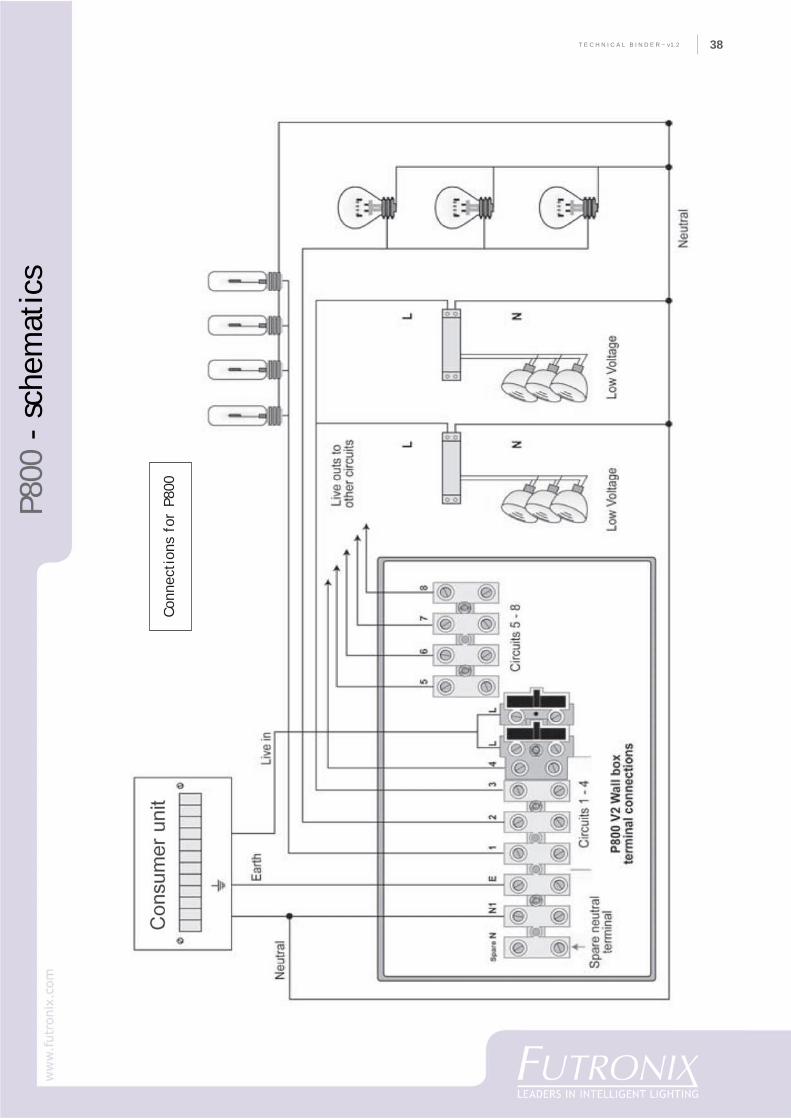
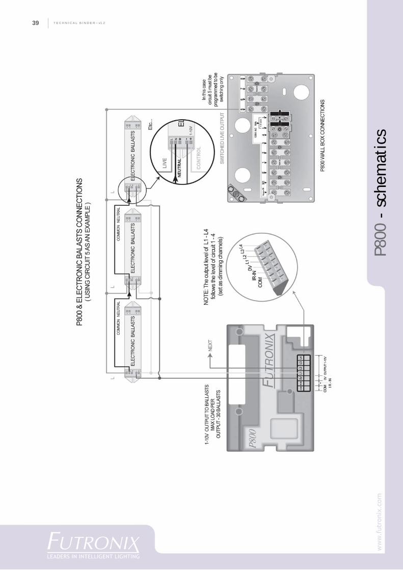
The P800 8-channel dimmer provides scenedimming control for up to 4 areas or rooms, witha 20-scene memory for each area. Up to eightP800 units can be connected together for a totalof 64 channels of lighting control. The P800’s rearconnector provides 4 channels of 1-10v industrystandard fluorescent dimming control, with up to30 dimmable ballasts connectable to each of the4 control outputs. The P800 can also be integratedinto AV equipment in a home, restaurant orconference room.
Typical applicationsResidential and light commercial applicationsinclude luxury houses, living rooms, hotel rooms,conference & seminar rooms, boardrooms, smallrestaurants & bars.
OperationUser operation is from wall-mounted switchplatesor by full function IR remote control handset. Anin-built X-Bus databus enables multi-pointswitching via connected outstation switchplates,and multi-room control via additional P400 or P800dimmers. P800 dimmers can also be controlled by3rd party Universal remote control devices (One-for-All, Pronto, etc.) and touch screens, via theindustry standard IR interface.
TimerThe P800 features a 24 hr 7 day timer withautomatic recall of up to 70 scene events per week(10 per day). Timer is battery backed to ensurecorrect timekeeping during power outages.
P800
sce
ne d
imm
er
T E C H N I C A L B I N D E R ~ v1.237
P800
- f
eatu
res
& s
peci
fica
tion
s
P800 - Features Full-featured all-digital scene dimmer Control for up to 8 circuits (channels) 4 channels of 1-10v fluorescent ballast dimming control 20 programmable scenes per room/area Multiple lighting zones - up to 4 zones / rooms
Outstation switch plates available - control lighting from more than one location
In-built X-Bus databus provides for: - multi-point switching and mastering via switchplates - multi-room control via connected P800/P400 dimmers Infra-red remote control supplied – commands available on most Universal Remote controls
Temporary circuit adjustment without save
Master raise and lower, Exit delay, Sleep timer & Security settings
24-hr 7-day event timer – up to 70 different events each week (10 per day)
In-built blue LED information display and infra-red receiver
Variable fade rates from 0.5 secs to 2 hours
Permanent memory
P800 - Electrical Specification Mains supply input voltage & frequency
220-240v AC 50Hz 120v AC 60Hz
Mains supply input current 16A (max.) incoming supply Channels 8 channels per P800 Max. number of channels with interconnected P800 systems
8 x P800’s can be interconnected = 64 channels
Zones 4 zones (areas/rooms) Switch panels 3 switch panels per P800 Dimming output (max.) 600W per channel (max.) Total dimmer load (max.) 2Kw across all 8 channels (max.) Dimming output (min.) No minimum load on any channel Dimming output (1-10v optional) 4 channels (1-10v) fluorescent regulation ballasts Switching output (max.) 600W per channel (max.) Load type Tungsten, mains halogen, neon & fluorescent
(HF), low voltage (magnetic & leading edge dimmable transformers)
Network connection X-Bus non-twisted pair Protection Fuses 2 x 8A Wallbox size (W,H,D) mm 160 x 102 x 65 mm (pre-wired wallbox supplied) Wallbox size USA (W,H,D) in. 61/4 x 4 x 25/8 in. (pre-wired wallbox supplied) Approvals CE, EN, UL
38
CO
MPA
NY
PR
OFI
LET E C H N I C A L B I N D E R ~ v1.2 38
P800
- s
chem
atic
s
Conn
ecti
ons
for
P800
T E C H N I C A L B I N D E R ~ v1.239
P800
- s
chem
atic
s
40
CO
MPA
NY
PR
OFI
LET E C H N I C A L B I N D E R ~ v1.2 40
P400
sce
ne d
imm
er
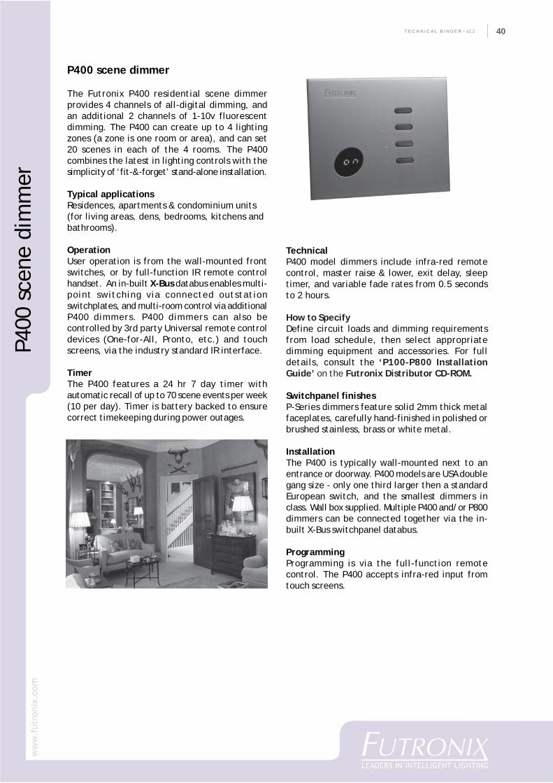
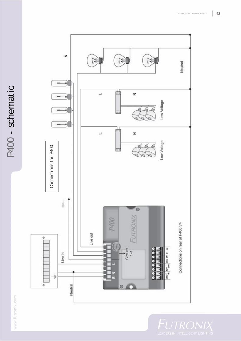
P400 scene dimmer
The Futronix P400 residential scene dimmerprovides 4 channels of all-digital dimming, andan additional 2 channels of 1-10v fluorescentdimming. The P400 can create up to 4 lightingzones (a zone is one room or area), and can set20 scenes in each of the 4 rooms. The P400combines the latest in lighting controls with thesimplicity of ‘fit-&-forget’ stand-alone installation.
Typical applicationsResidences, apartments & condominium units(for living areas, dens, bedrooms, kitchens andbathrooms).
OperationUser operation is from the wall-mounted frontswitches, or by full-function IR remote controlhandset. An in-built X-Bus databus enables multi-point switching via connected outstationswitchplates, and multi-room control via additionalP400 dimmers. P400 dimmers can also becontrolled by 3rd party Universal remote controldevices (One-for-All, Pronto, etc.) and touchscreens, via the industry standard IR interface.
TimerThe P400 features a 24 hr 7 day timer withautomatic recall of up to 70 scene events per week(10 per day). Timer is battery backed to ensurecorrect timekeeping during power outages.
TechnicalP400 model dimmers include infra-red remotecontrol, master raise & lower, exit delay, sleeptimer, and variable fade rates from 0.5 secondsto 2 hours.
How to SpecifyDefine circuit loads and dimming requirementsfrom load schedule, then select appropriatedimming equipment and accessories. For fulldetails, consult the ‘P100-P800 InstallationGuide’ on the Futronix Distributor CD-ROM.
Switchpanel finishesP-Series dimmers feature solid 2mm thick metalfaceplates, carefully hand-finished in polished orbrushed stainless, brass or white metal.
InstallationThe P400 is typically wall-mounted next to anentrance or doorway. P400 models are USA doublegang size - only one third larger then a standardEuropean switch, and the smallest dimmers inclass. Wall box supplied. Multiple P400 and/or P800dimmers can be connected together via the in-built X-Bus switchpanel databus.
ProgrammingProgramming is via the full-function remotecontrol. The P400 accepts infra-red input fromtouch screens.
T E C H N I C A L B I N D E R ~ v1.241
P400
- f
eatu
res
& s
peci
fica
tion
s
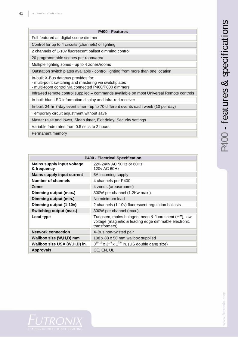
P400 - Features Full-featured all-digital scene dimmer
Control for up to 4 circuits (channels) of lighting
2 channels of 1-10v fluorescent ballast dimming control
20 programmable scenes per room/area
Multiple lighting zones - up to 4 zones/rooms
Outstation switch plates available - control lighting from more than one location
In-built X-Bus databus provides for: - multi-point switching and mastering via switchplates - multi-room control via connected P400/P800 dimmers Infra-red remote control supplied – commands available on most Universal Remote controls
In-built blue LED information display and infra-red receiver
In-built 24-hr 7-day event timer - up to 70 different events each week (10 per day)
Temporary circuit adjustment without save
Master raise and lower, Sleep timer, Exit delay, Security settings
Variable fade rates from 0.5 secs to 2 hours
Permanent memory
P400 - Electrical Specification Mains supply input voltage & frequency
220-240v AC 50Hz or 60Hz 120v AC 60Hz
Mains supply input current 6A incoming supply Number of channels 4 channels per P400 Zones 4 zones (areas/rooms) Dimming output (max.) 300W per channel (1.2Kw max.) Dimming output (min.) No minimum load Dimming output (1-10v) 2 channels (1-10v) fluorescent regulation ballasts Switching output (max.) 300W per channel (max.) Load type Tungsten, mains halogen, neon & fluorescent (HF), low
voltage (magnetic & leading edge dimmable electronic transformers)
Network connection X-Bus non-twisted pair Wallbox size (W,H,D) mm 108 x 88 x 50 mm wallbox supplied Wallbox size USA (W,H,D) in. 315/16 x 31/8 x 17/8 in. (US double gang size) Approvals CE, EN, UL
42
CO
MPA
NY
PR
OFI
LET E C H N I C A L B I N D E R ~ v1.2 42
P400
- s
chem
atic
Conn
ecti
ons
for
P400
T E C H N I C A L B I N D E R ~ v1.243
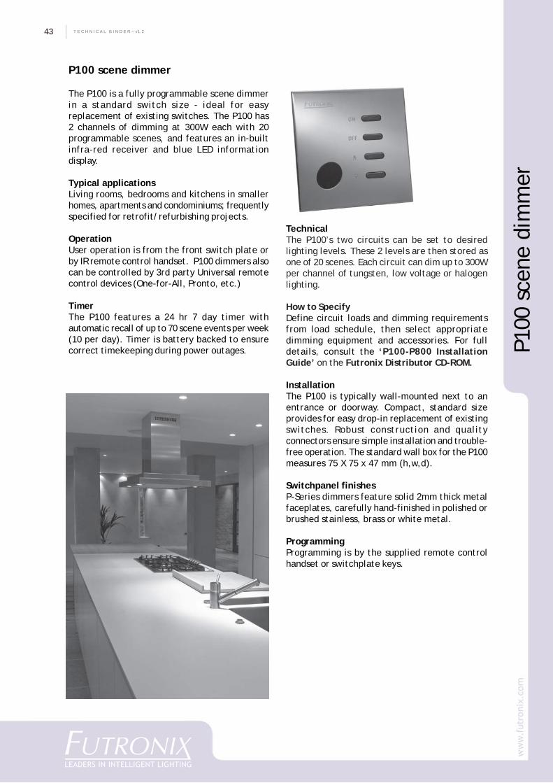
P100 scene dimmer
The P100 is a fully programmable scene dimmerin a standard switch size - ideal for easyreplacement of existing switches. The P100 has2 channels of dimming at 300W each with 20programmable scenes, and features an in-builtinfra-red receiver and blue LED informationdisplay.
Typical applicationsLiving rooms, bedrooms and kitchens in smallerhomes, apartments and condominiums; frequentlyspecified for retrofit/refurbishing projects.
OperationUser operation is from the front switch plate orby IR remote control handset. P100 dimmers alsocan be controlled by 3rd party Universal remotecontrol devices (One-for-All, Pronto, etc.)
TimerThe P100 features a 24 hr 7 day timer withautomatic recall of up to 70 scene events per week(10 per day). Timer is battery backed to ensurecorrect timekeeping during power outages.
TechnicalThe P100’s two circuits can be set to desiredlighting levels. These 2 levels are then stored asone of 20 scenes. Each circuit can dim up to 300Wper channel of tungsten, low voltage or halogenlighting.
How to SpecifyDefine circuit loads and dimming requirementsfrom load schedule, then select appropriatedimming equipment and accessories. For fulldetails, consult the ‘P100-P800 InstallationGuide’ on the Futronix Distributor CD-ROM.
InstallationThe P100 is typically wall-mounted next to anentrance or doorway. Compact, standard sizeprovides for easy drop-in replacement of existingswitches. Robust construction and qualityconnectors ensure simple installation and trouble-free operation. The standard wall box for the P100measures 75 X 75 x 47 mm (h,w,d).
Switchpanel finishesP-Series dimmers feature solid 2mm thick metalfaceplates, carefully hand-finished in polished orbrushed stainless, brass or white metal.
ProgrammingProgramming is by the supplied remote controlhandset or switchplate keys.
P100
sce
ne d
imm
er
44
CO
MPA
NY
PR
OFI
LET E C H N I C A L B I N D E R ~ v1.2 44
P100
- f
eatu
res
& s
peci
fica
tion
s
P100 - Features Controls 2 circuits of lighting 300W per channel dimmer Drop-in replacement for existing dimmer switches (requires neutral) 20 programmable scenes per channel Infra-red remote control supplied - commands can be ‘learnt’ by any universal learning remote control In-built 24-hr 7-day timer Temporary circuit adjustment without save Master raise and lower, Sleep timer, Exit delay & Security settings Variable fade rates from 0.5 secs to 2 hours In-built blue LED information display and infra-red receiver Programmable fade-rates (from 0.5 seconds to 2 hours) Permanent memory
P100 - Electrical Specification Mains supply input voltage & frequency
220-240v AC 50Hz or 60Hz 120v AC 60Hz
Mains supply input current 6A incoming supply Number of channels 2 Dimming output (max.) 300W per channel (600W max.) Dimming output (min.) No minimum load Switching output (max.) 300W per channel (600W max.) Load type Tungsten, mains halogen, low voltage
(magnetic & leading edge dimmable electronic transformers), fluorescent (HF)
Wallbox size (W,H,D) mm 75 x 75 x 47 mm Approvals CE, EN
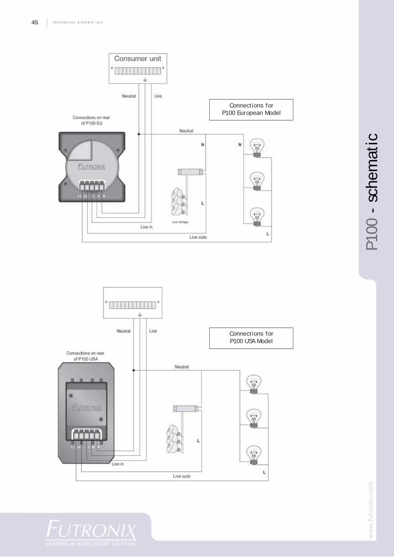
T E C H N I C A L B I N D E R ~ v1.245
P100
- s
chem
atic
Connections forP100 European Model
Connections forP100 USA Model
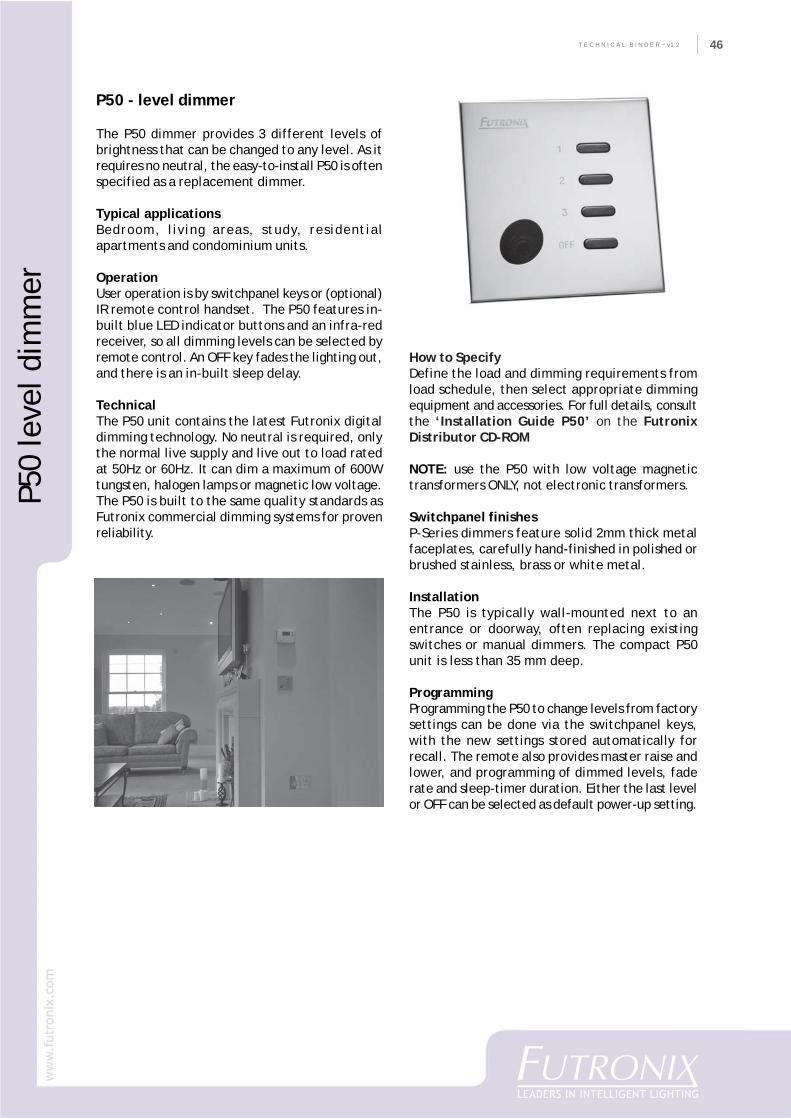
46
CO
MPA
NY
PR
OFI
LET E C H N I C A L B I N D E R ~ v1.2 46
P50 - level dimmer
The P50 dimmer provides 3 different levels ofbrightness that can be changed to any level. As itrequires no neutral, the easy-to-install P50 is oftenspecified as a replacement dimmer.
Typical applicationsBedroom, living areas, study, residentialapartments and condominium units.
OperationUser operation is by switchpanel keys or (optional)IR remote control handset. The P50 features in-built blue LED indicator buttons and an infra-redreceiver, so all dimming levels can be selected byremote control. An OFF key fades the lighting out,and there is an in-built sleep delay.
TechnicalThe P50 unit contains the latest Futronix digitaldimming technology. No neutral is required, onlythe normal live supply and live out to load ratedat 50Hz or 60Hz. It can dim a maximum of 600Wtungsten, halogen lamps or magnetic low voltage.The P50 is built to the same quality standards asFutronix commercial dimming systems for provenreliability.
How to SpecifyDefine the load and dimming requirements fromload schedule, then select appropriate dimmingequipment and accessories. For full details, consultthe ‘Installation Guide P50’ on the FutronixDistributor CD-ROM
NOTE: use the P50 with low voltage magnetictransformers ONLY, not electronic transformers.
Switchpanel finishesP-Series dimmers feature solid 2mm thick metalfaceplates, carefully hand-finished in polished orbrushed stainless, brass or white metal.
InstallationThe P50 is typically wall-mounted next to anentrance or doorway, often replacing existingswitches or manual dimmers. The compact P50unit is less than 35 mm deep.
ProgrammingProgramming the P50 to change levels from factorysettings can be done via the switchpanel keys,with the new settings stored automatically forrecall. The remote also provides master raise andlower, and programming of dimmed levels, faderate and sleep-timer duration. Either the last levelor OFF can be selected as default power-up setting.
P50
leve
l dim
mer
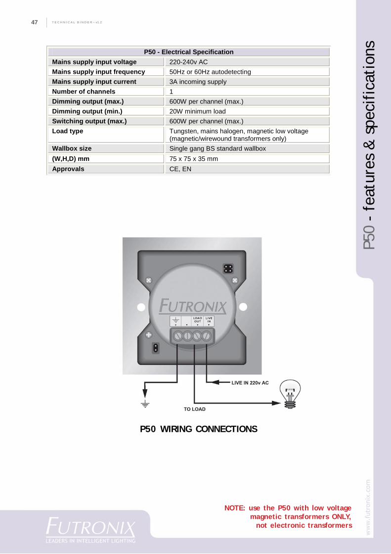
T E C H N I C A L B I N D E R ~ v1.247
P50
- fe
atur
es &
spe
cifi
cati
ons
NOTE: use the P50 with low voltagemagnetic transformers ONLY,
not electronic transformers
P50 - Electrical Specification Mains supply input voltage 220-240v AC Mains supply input frequency 50Hz or 60Hz autodetecting Mains supply input current 3A incoming supply Number of channels 1 Dimming output (max.) 600W per channel (max.) Dimming output (min.) 20W minimum load Switching output (max.) 600W per channel (max.) Load type Tungsten, mains halogen, magnetic low voltage
(magnetic/wirewound transformers only) Wallbox size Single gang BS standard wallbox (W,H,D) mm 75 x 75 x 35 mm Approvals CE, EN
P50 WIRING CONNECTIONS
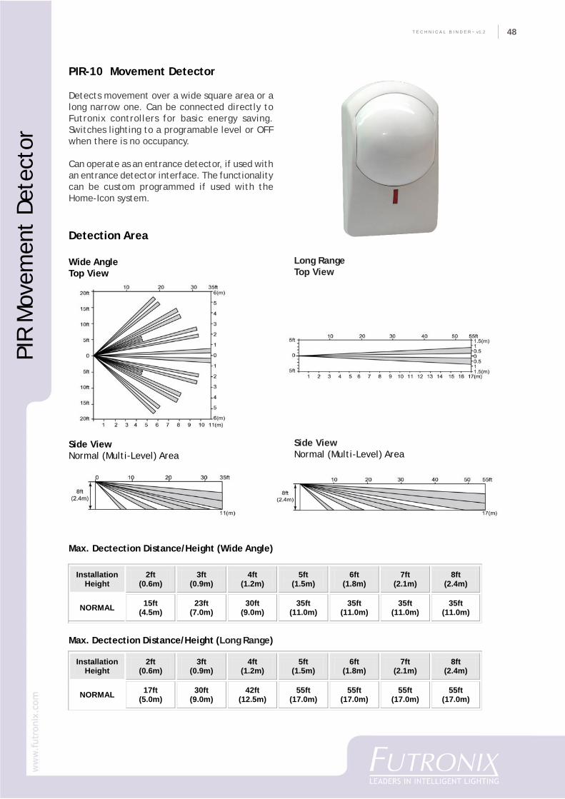
48
CO
MPA
NY
PR
OFI
LET E C H N I C A L B I N D E R ~ v1.2 48
PIR
Mov
emen
t De
tect
or
PIR-10 Movement Detector
Detects movement over a wide square area or along narrow one. Can be connected directly toFutronix controllers for basic energy saving.Switches lighting to a programable level or OFFwhen there is no occupancy.
Can operate as an entrance detector, if used withan entrance detector interface. The functionalitycan be custom programmed if used with theHome-Icon system.
Detection Area
Wide AngleTop View
Side ViewNormal (Multi-Level) Area
Max. Dectection Distance/Height (Wide Angle)
Max. Dectection Distance/Height (Long Range)
Long RangeTop View
Side ViewNormal (Multi-Level) Area
Installation Height
2ft (0.6m)
3ft (0.9m)
4ft (1.2m)
5ft (1.5m)
6ft (1.8m)
7ft (2.1m)
8ft (2.4m)
NORMAL 15ft (4.5m)
23ft (7.0m)
30ft (9.0m)
35ft (11.0m)
35ft (11.0m)
35ft (11.0m)
35ft (11.0m)
Installation Height
2ft (0.6m)
3ft (0.9m)
4ft (1.2m)
5ft (1.5m)
6ft (1.8m)
7ft (2.1m)
8ft (2.4m)
NORMAL 17ft (5.0m)
30ft (9.0m)
42ft (12.5m)
55ft (17.0m)
55ft (17.0m)
55ft (17.0m)
55ft (17.0m)
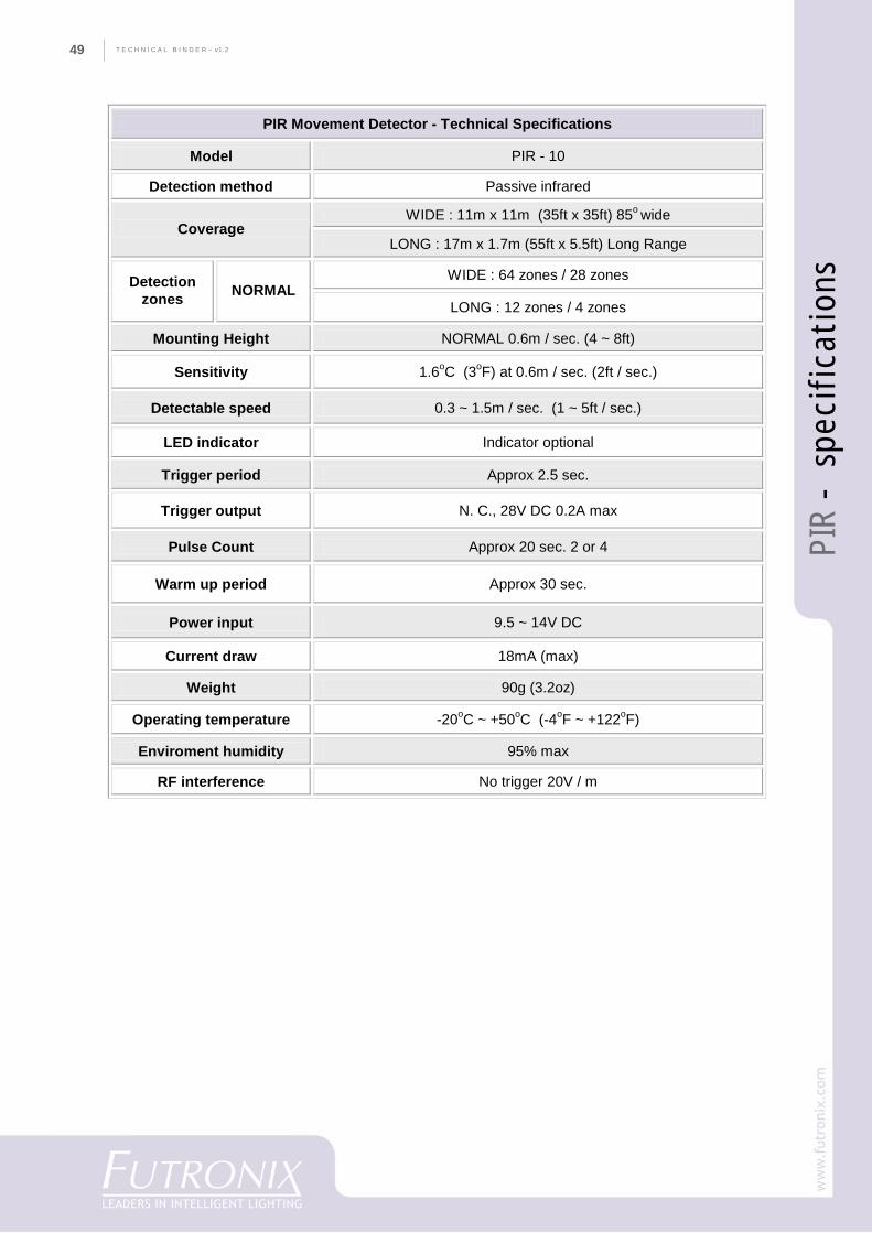
T E C H N I C A L B I N D E R ~ v1.249
PIR
- s
peci
fica
tion
s
PIR Movement Detector - Technical Specifications
Model PIR - 10
Detection method Passive infrared
WIDE : 11m x 11m (35ft x 35ft) 85o wide Coverage
LONG : 17m x 1.7m (55ft x 5.5ft) Long Range
WIDE : 64 zones / 28 zones Detection zones NORMAL
LONG : 12 zones / 4 zones
Mounting Height NORMAL 0.6m / sec. (4 ~ 8ft)
Sensitivity 1.6oC (3oF) at 0.6m / sec. (2ft / sec.)
Detectable speed 0.3 ~ 1.5m / sec. (1 ~ 5ft / sec.)
LED indicator Indicator optional
Trigger period Approx 2.5 sec.
Trigger output N. C., 28V DC 0.2A max
Pulse Count Approx 20 sec. 2 or 4
Warm up period Approx 30 sec.
Power input 9.5 ~ 14V DC
Current draw 18mA (max)
Weight 90g (3.2oz)
Operating temperature -20oC ~ +50oC (-4oF ~ +122oF)
Enviroment humidity 95% max
RF interference No trigger 20V / m
50
CO
MPA
NY
PR
OFI
LET E C H N I C A L B I N D E R ~ v1.2 50
PFX
Syst
em S
peci
fica
tion
s
PFX System
Detailed Specifications
T E C H N I C A L B I N D E R ~ v1.251
The Futronix PFX ProgrammableScene Dimmer
The PFX programmable architectural lightingscene dimmer is the latest generation ofprofessional all-digital dimmers from Futronix.The PFX is one of the most sophisticated andcost effective high-end dimming systemsavailable. Its’ modular design means that it iseasy to specify, install and commission.
Description of the PFX system
The PFX is a modular system built around a rangeof standard-sized chassis. Each chassis has its’own intelligence and comes in modules of 8, 12,16, or 32 channels. The system has in-builtdistributed intellegence, allowing for dimmerracks to be located throughout a building andthen interlinked as one seamless sytem. The PFXis designed to be very flexible with allparameters being set up from remote handsetor laptop after installation.
As many PFX’s as needed can be used to buildsystems of unlimited size. Any PFX can beprogrammed to be a master or a slave; onemaster can control up to 7 slaves. Each PFX canhave up to 16 channels giving up to 128 channelsin each local area. 32 of these systems can berun on one RS485 PC network giving a total of4096 circuits. As many networks can be run asthere are PC expansion slots available, makingthe system unlimited in size.
The PFX is very flexible, making it ideal for bothlarger and medium sized projects. Typical usesare hotels, convention centres, cinemas,conference facilities, restaurants andcommercial buildings. The PFX can be used toform a system from just a few channels up toseveral thousand.
The inherent flexibility of the PFX system meansthat it is an easy system to specify and install.No matter how complex the customer’s
requirements are, the system can be configuredto meet their needs.
The PFX system can be designed to haveunlimited channels and zones. It has RS485 andbuilding management (BMS) interfaces, and itcan operate as a part of a network or part of astand-alone system. Programming can be donefrom a PC/laptop, remote control or LCD touchscreen.
Any of the channels onboard a PFX can be set tooperate in any zone. The zones can be fixed, ordependent on the position of room partitions ina multi-room conference room. There are 16possible zones and multiple banks of scenes foreach combination of partition positions.Similarly each circuit can be set in software tooperate on any phase: RED, YELLOW or BLUE.There is in-built password protection for eachlevel of user/installer/programmer access.
Each PFX chassis contains the latest generation16 bit controller and hard fired digital dimmerunits. Being all-digital means that the PFX ismore reliable more accurate, and quieter thanordinary dimmers.
The fade resolution is 1024 levels for all fadeand cross fade functions. Each scene can haveits own fade-in duration programmed accordingto preceding scene or time. All the dimmerparameters are stored in a plug-in 16Kb EEprom.This allows instant control board changing withall customer pre-set parameters being retained.Data life with power off is 100 years with 1mread/write cycles. For extra security allparameters can be uploaded and stored on PC.
Hardware options
Occupancy detectors & daylight cells can beconnected to the system. There are inputs whichcan be connected to a fire and/or security alarm.If a voltage of between 10-30v DC is applied tothe input the lights will switch to full ONregardless of any other function or input. Thelighting will only return to the previous levelwhen the alarm condition is removed.
PFX
Syst
em S
peci
fica
tion
s
52
CO
MPA
NY
PR
OFI
LET E C H N I C A L B I N D E R ~ v1.2 52
PFX FUNCTIONALLITY
Each PFX has a latest generation onboard microcontroller, which handles all the functions requiredincluding the following:
• Calculating the AC mains timing zero crossing point for all 3 phases• Firing the alternistor/triacs 100 times per second at the correct angle in each of the three mains
cycle phases• Phase angle auto-lock for local generators and uninterruptible power supplies (UPS)• Calculating the fade angle for each channel with 1K steps of digital resolution• Determining mains voltage compensation level• Communicating and transferring information on RS485 bus with up to 255 other PFX systems• Communicating on local bus with all local control devices including: switch panels,
daylight level device, occupancy detector• Communicating with central PC sending, receiving and acting on information• Communicating with floor reception controller & BMS system• Decoding and acting on remote control signals• Handling all programming logic and non-volatile memory• Operating onboard 24 hour 365 day timer.• Accepting inputs from partition switches for zoning• Acting on information received and decoded by switch panels from remote control handset.
Description Of Dimming
PFX dimmers are fitted with alternistors rated at 40A 1000v. Alternistors have an excellent MTBF. Allinternal cable is rated at twice its maximum loading. Each channel is fitted with a toroidally wound,iron powder, interference suppression choke which limits the rise-time of the switch on transient tobetter that 200uS. The chokes give excellent radio interference suppression.
PFX Systems satisfy both BS800 & EC approvals for EMC regulations:BS EN50081-1:1995BS EN50082-1:1995BS EN55015-1:1996BS EN55022-1:1995BS EN60950-1:1995BS EN60439-1:1996EMC directive 89/336/EC
Rona Approval for electrical circuit breakers/switchesDaewoo Shipping approval.
Dimmer PerformanceThe efficiency of each dimmer is up to 98%. Aluminum heatsinks keep the internal temperature rise toless than 25o C above external ambient. The individual circuits in each unit can be defined as ‘S’ truepower curve or non dim circuits.
Audible noise from a 16 channel 10A dimmer fully loaded at 50% dimming is equal or <30db@1m.
PFX
Syst
em S
peci
fica
tion
s
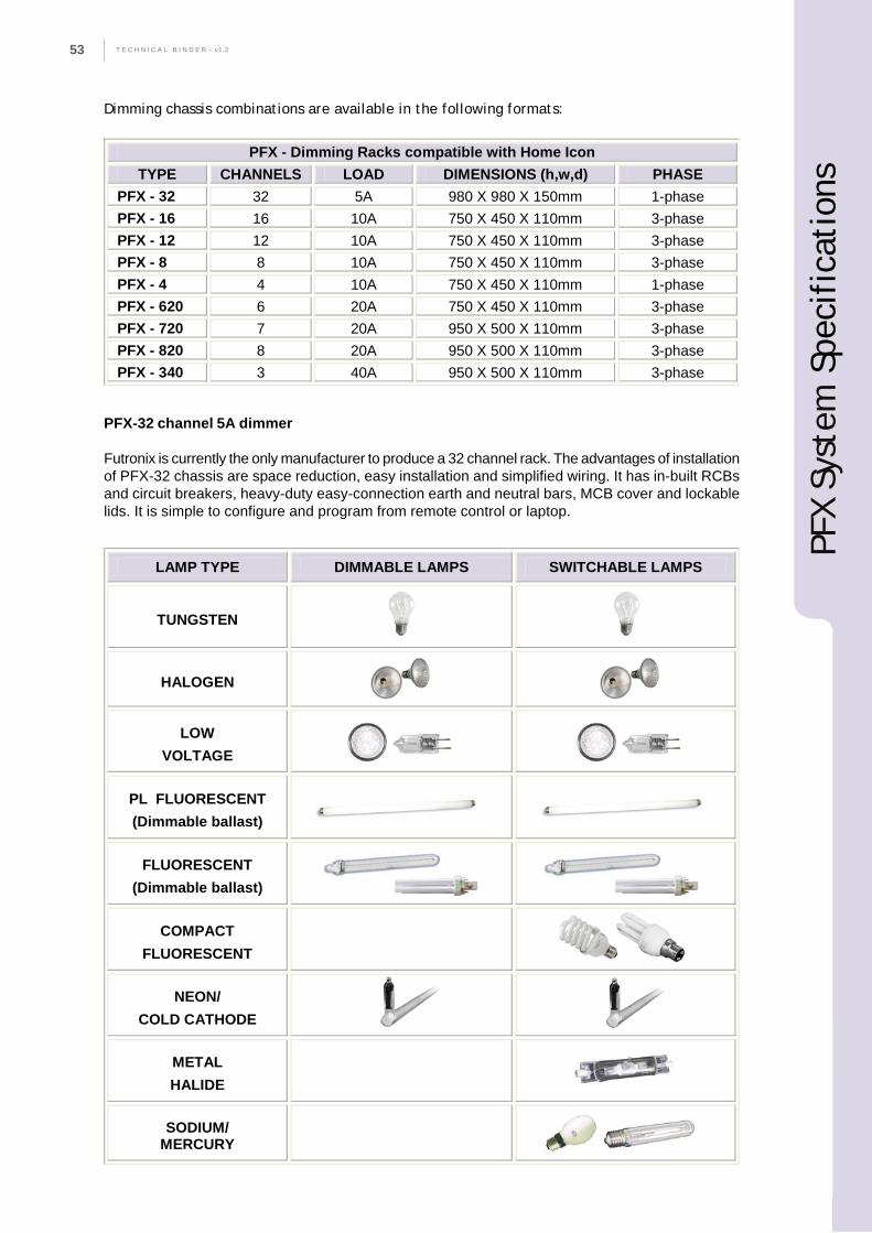
T E C H N I C A L B I N D E R ~ v1.253
Dimming chassis combinations are available in the following formats:
PFX-32 channel 5A dimmer
Futronix is currently the only manufacturer to produce a 32 channel rack. The advantages of installationof PFX-32 chassis are space reduction, easy installation and simplified wiring. It has in-built RCBsand circuit breakers, heavy-duty easy-connection earth and neutral bars, MCB cover and lockablelids. It is simple to configure and program from remote control or laptop.
PFX - Dimming Racks compatible with Home Icon TYPE CHANNELS LOAD DIMENSIONS (h,w,d) PHASE
PFX - 32 32 5A 980 X 980 X 150mm 1-phase PFX - 16 16 10A 750 X 450 X 110mm 3-phase PFX - 12 12 10A 750 X 450 X 110mm 3-phase PFX - 8 8 10A 750 X 450 X 110mm 3-phase PFX - 4 4 10A 750 X 450 X 110mm 1-phase PFX - 620 6 20A 750 X 450 X 110mm 3-phase PFX - 720 7 20A 950 X 500 X 110mm 3-phase PFX - 820 8 20A 950 X 500 X 110mm 3-phase PFX - 340 3 40A 950 X 500 X 110mm 3-phase
LAMP TYPE DIMMABLE LAMPS SWITCHABLE LAMPS
TUNGSTEN
HALOGEN
LOW VOLTAGE
PL FLUORESCENT (Dimmable ballast)
FLUORESCENT (Dimmable ballast)
COMPACT FLUORESCENT
NEON/ COLD CATHODE
METAL HALIDE
SODIUM/ MERCURY
PFX
Syst
em S
peci
fica
tion
s
54
CO
MPA
NY
PR
OFI
LET E C H N I C A L B I N D E R ~ v1.2 54
Description of Switch Panels
The PFX system is available with a large rangeof switch panels in a variety of styles, sizes andfinishes. The standard switch panels are single/double gang European and USA sizes. Thestandard finishes available are white, brass, andstainless steel in a range of styles.
A maximum of 32 switch panels can be connectedto each PFX chassis. Switch panels can be locatedup to 600m away from the chassis, with one 4core cable looped (daisy chained) from oneswitch panel to the next.
Each switch panel has its own uniqueprogrammable address, set in software. Eachswitch panel can also be set to control any zoneor any number of zones. This can be re-programmed as required by the commissioningengineer. The PFX communicates with the switchpanels, exchanging information with each one.Some switch panels have in-built displays andremote control receiver with a working rangeof 40 feet or more. The switch panels receiveand decode the remote control signal, then passthe command on to the PFX. The PFXautomatically knows from which switch panelthe remote control command was received. Thismeans that when the PFX is used in zoning modeany remote control handset can be used in anyroom. The system can be programmed from anyswitch panel using the infra-red remote control.In addition the system can be programmed froma double-gang switch panel.
TYPICAL SWITCH PANEL KEY FUNCTIONS
There are 15 standard template variants. (Seethe section on switch panels for more details)Many other switch panels and configurations areavailable to special order.
SOFTWARE
The programming/operating software is designedto run in Windows XP on a Pentium based PCwith 500Mb free hard disk space. The Windowssoftware allows multi-level access to the systemfor users, managers, installers and commissioningengineers.
Level one allows the system to be pre- programmed
Level two set-up an installation master/slave, network, switch panels etc.
Level three scene, fade, time, block, delay, switch parameters entered
Level four operating, system monitoring, re-programming by management
Level five operating, temporary adjustment, limited re-programming
Level six operating, temporary adjustment
Level seven operating only
PFX
Syst
em S
peci
fica
tion
s
T E C H N I C A L B I N D E R ~ v1.255
PFX Windows software menus
• OPEN MENUAllows the file which holds all the informationfor the complete site to be opened.
• LOCK KEY MENUThe password entered allows users differentlevels of access (see above).
• SITE MENUThis menu can be customized to show a completemulti-level plan of the entire project includinginterior and exterior lighting.
• AREA MENUThis menu can be customized to show a plan ofeach individual area.
• ZONE/SCENE MENUAllows selection of the zone and the differentscenes within each zone. Any circuit can be setinto any zone from this menu. Physical circuitscan be swapped with control circuits.
• CIRCUIT MENU - MAIN MENUAll the circuits in the selected zone are displayed(up to a total of 128 circuits in one system). Allthe circuit parameters can be altered from thismenu. Each of the 128 circuits can be set up tooperate on any phase or as a switching ordimming channel. On each scene the circuits canbe programmed, temporarily re-adjusted,modified, set for on/off switching and blockdown/up loaded.
• SITE/ AREA/ CIRCUIT/ SCENE NAMESAll of the above can be assigned with descriptivenames. They can be stored locally or globally.These descriptive names will appear whereverthey are used throughout the system.
• MASTER CIRCUITThe master circuits levels in each zone can beadjusted temporarily or permanently.
• TIME CLOCK24 hour 365 day time clock with unlimited timerevents which can be set up for selecting differentscenes.
• NETWORK ADDRESSAny PFX can be set to be a Master or Slave; thismenu lets the installer set up the addresses ofthe chassis and the network/site addressing.
PROGRAMMING OF THE PFX
The PFX system can be programmed by infra-red remote control, touch screen or laptop/PC.If using a laptop to configure the system, theFutronix Light Scene controller software isrequired along with a PCMCIA-RS485 converter.If a PC is used then a USB-RS485 convertor isrequired. Both these items are available fromFutronix. The software is available by requestand also online.
The Windows software requires a PC runningWindows XP. The software has its own load andconfiguration menu. The RS485 converter comeswith its own lead to connect it to the RJ9 socketon the PFX dimmer chassis. For longer lengths acustom lead may be required.
PFX
Syst
em S
peci
fica
tion
s
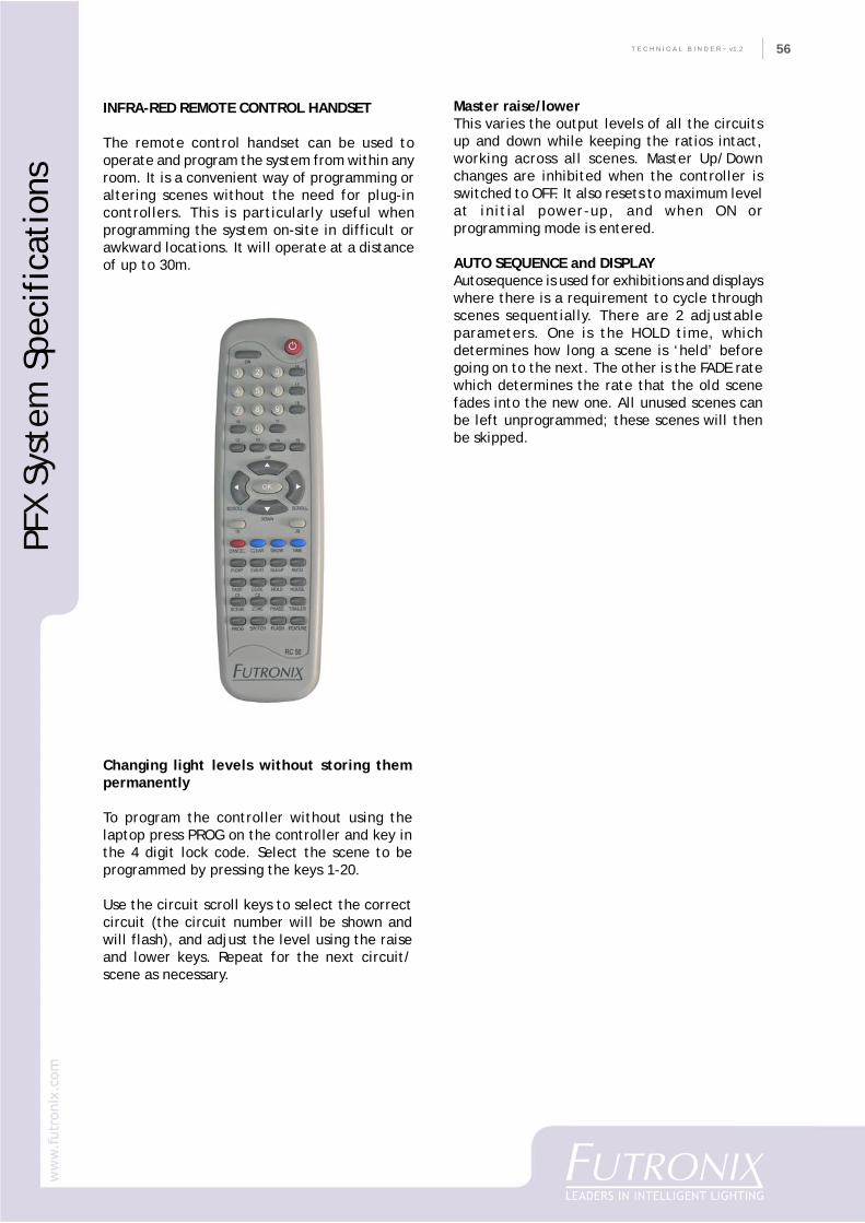
56
CO
MPA
NY
PR
OFI
LET E C H N I C A L B I N D E R ~ v1.2 56
INFRA-RED REMOTE CONTROL HANDSET
The remote control handset can be used tooperate and program the system from within anyroom. It is a convenient way of programming oraltering scenes without the need for plug-incontrollers. This is particularly useful whenprogramming the system on-site in difficult orawkward locations. It will operate at a distanceof up to 30m.
Changing light levels without storing thempermanently
To program the controller without using thelaptop press PROG on the controller and key inthe 4 digit lock code. Select the scene to beprogrammed by pressing the keys 1-20.
Use the circuit scroll keys to select the correctcircuit (the circuit number will be shown andwill flash), and adjust the level using the raiseand lower keys. Repeat for the next circuit/scene as necessary.
Master raise/lowerThis varies the output levels of all the circuitsup and down while keeping the ratios intact,working across all scenes. Master Up/Downchanges are inhibited when the controller isswitched to OFF. It also resets to maximum levelat initial power-up, and when ON orprogramming mode is entered.
AUTO SEQUENCE and DISPLAYAutosequence is used for exhibitions and displayswhere there is a requirement to cycle throughscenes sequentially. There are 2 adjustableparameters. One is the HOLD time, whichdetermines how long a scene is ‘held’ beforegoing on to the next. The other is the FADE ratewhich determines the rate that the old scenefades into the new one. All unused scenes canbe left unprogrammed; these scenes will thenbe skipped.
PFX
Syst
em S
peci
fica
tion
s
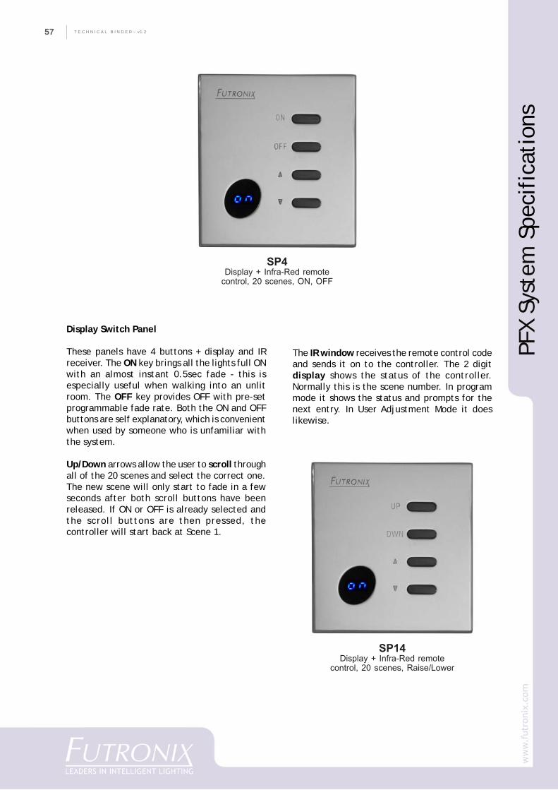
T E C H N I C A L B I N D E R ~ v1.257
SP4Display + Infra-Red remote
control, 20 scenes, ON, OFF
Display Switch Panel
These panels have 4 buttons + display and IRreceiver. The ON key brings all the lights full ONwith an almost instant 0.5sec fade - this isespecially useful when walking into an unlitroom. The OFF key provides OFF with pre-setprogrammable fade rate. Both the ON and OFFbuttons are self explanatory, which is convenientwhen used by someone who is unfamiliar withthe system.
Up/Down arrows allow the user to scroll throughall of the 20 scenes and select the correct one.The new scene will only start to fade in a fewseconds after both scroll buttons have beenreleased. If ON or OFF is already selected andthe scroll buttons are then pressed, thecontroller will start back at Scene 1.
The IR window receives the remote control codeand sends it on to the controller. The 2 digitdisplay shows the status of the controller.Normally this is the scene number. In programmode it shows the status and prompts for thenext entry. In User Adjustment Mode it doeslikewise.
SP14Display + Infra-Red remote
control, 20 scenes, Raise/Lower
PFX
Syst
em S
peci
fica
tion
s
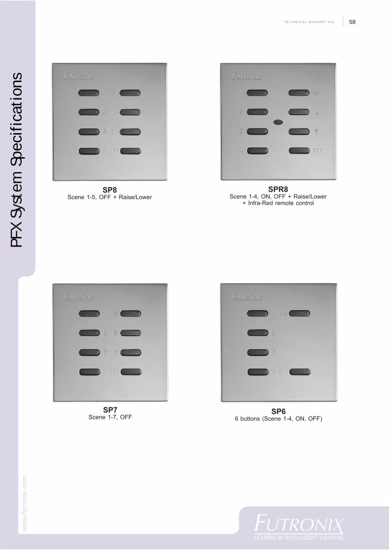
58
CO
MPA
NY
PR
OFI
LET E C H N I C A L B I N D E R ~ v1.2 58
SPR8Scene 1-4, ON, OFF + Raise/Lower
+ Infra-Red remote control
SP8Scene 1-5, OFF + Raise/Lower
SP66 buttons (Scene 1-4, ON, OFF)
SP7Scene 1-7, OFF
PFX
Syst
em S
peci
fica
tion
s
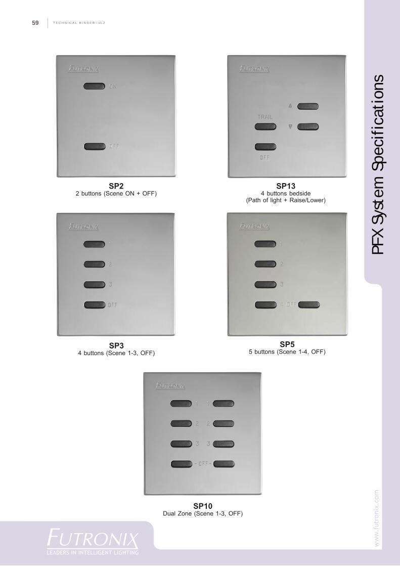
T E C H N I C A L B I N D E R ~ v1.259
SP10Dual Zone (Scene 1-3, OFF)
SP22 buttons (Scene ON + OFF)
SP134 buttons bedside
(Path of light + Raise/Lower)
SP55 buttons (Scene 1-4, OFF)
SP34 buttons (Scene 1-3, OFF)
PFX
Syst
em S
peci
fica
tion
s
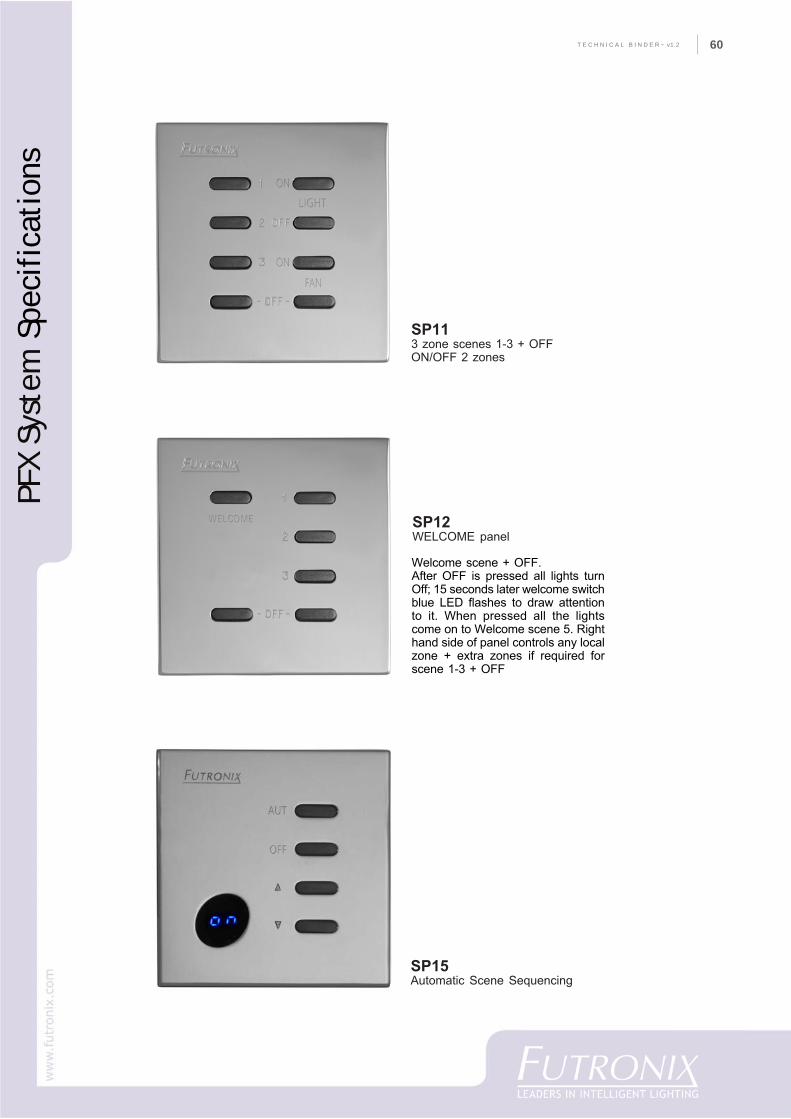
60
CO
MPA
NY
PR
OFI
LET E C H N I C A L B I N D E R ~ v1.2 60
SP113 zone scenes 1-3 + OFFON/OFF 2 zones
SP12WELCOME panel
Welcome scene + OFF.After OFF is pressed all lights turnOff; 15 seconds later welcome switchblue LED flashes to draw attentionto it. When pressed all the lightscome on to Welcome scene 5. Righthand side of panel controls any localzone + extra zones if required forscene 1-3 + OFF
SP15Automatic Scene Sequencing
PFX
Syst
em S
peci
fica
tion
s
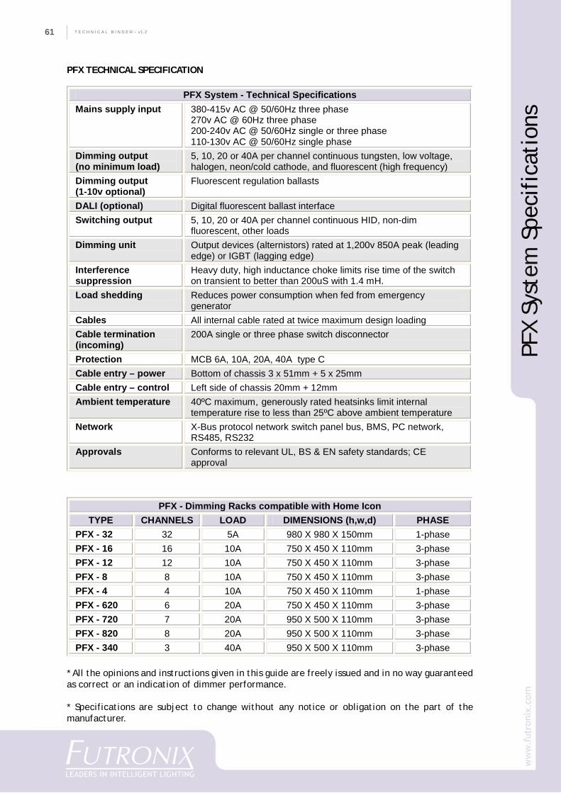
T E C H N I C A L B I N D E R ~ v1.261
PFX TECHNICAL SPECIFICATION
* All the opinions and instructions given in this guide are freely issued and in no way guaranteedas correct or an indication of dimmer performance.
* Specifications are subject to change without any notice or obligation on the part of themanufacturer.
PFX System - Technical Specifications Mains supply input 380-415v AC @ 50/60Hz three phase
270v AC @ 60Hz three phase 200-240v AC @ 50/60Hz single or three phase 110-130v AC @ 50/60Hz single phase
Dimming output (no minimum load)
5, 10, 20 or 40A per channel continuous tungsten, low voltage, halogen, neon/cold cathode, and fluorescent (high frequency)
Dimming output (1-10v optional)
Fluorescent regulation ballasts
DALI (optional) Digital fluorescent ballast interface Switching output 5, 10, 20 or 40A per channel continuous HID, non-dim
fluorescent, other loads Dimming unit Output devices (alternistors) rated at 1,200v 850A peak (leading
edge) or IGBT (lagging edge) Interference suppression
Heavy duty, high inductance choke limits rise time of the switch on transient to better than 200uS with 1.4 mH.
Load shedding Reduces power consumption when fed from emergency generator
Cables All internal cable rated at twice maximum design loading Cable termination (incoming)
200A single or three phase switch disconnector
Protection MCB 6A, 10A, 20A, 40A type C Cable entry – power Bottom of chassis 3 x 51mm + 5 x 25mm Cable entry – control Left side of chassis 20mm + 12mm Ambient temperature 40ºC maximum, generously rated heatsinks limit internal
temperature rise to less than 25ºC above ambient temperature
Network X-Bus protocol network switch panel bus, BMS, PC network, RS485, RS232
Approvals Conforms to relevant UL, BS & EN safety standards; CE approval
PFX - Dimming Racks compatible with Home Icon TYPE CHANNELS LOAD DIMENSIONS (h,w,d) PHASE
PFX - 32 32 5A 980 X 980 X 150mm 1-phase PFX - 16 16 10A 750 X 450 X 110mm 3-phase PFX - 12 12 10A 750 X 450 X 110mm 3-phase PFX - 8 8 10A 750 X 450 X 110mm 3-phase PFX - 4 4 10A 750 X 450 X 110mm 1-phase PFX - 620 6 20A 750 X 450 X 110mm 3-phase PFX - 720 7 20A 950 X 500 X 110mm 3-phase PFX - 820 8 20A 950 X 500 X 110mm 3-phase PFX - 340 3 40A 950 X 500 X 110mm 3-phase
PFX
Syst
em S
peci
fica
tion
s
62
CO
MPA
NY
PR
OFI
LET E C H N I C A L B I N D E R ~ v1.2 62
M & E Specification
M &
E S
peci
fica
tion
T E C H N I C A L B I N D E R ~ v1.263
Futronix PFX Programmable Scene Dimmer- System Specifications for M & E Consultants
PART 1 – GENERALA. The lighting control system should be CE marked, and conform to BS standards.The dimmer system must satisfy both BS800 & EC approvals for EMC regulations:BS EN50081-1:1995BS EN50082-1:1995BS EN55015-1:1996BS EN55022-1:1996BS EN60950-1:1996BS EN60439-1:1994BS EN60669-2-1-1:2004Rona Approval for electrical circuit breakers/switches.
PART 2 – PRODUCTSAcceptable manufacturers - Futronix Ltd.The listing of a manufacturer as “acceptable” does not imply that the system has automatic approval.It is the sole responsibility of the electrical contractor to ensure that any price quotations receivedand submittals made are for devices that meet or exceed the specification.
Dimmer Performance1) The lighting dimmer control system should comprise a number of all-digital dimmer racks. This
system should control all the relevant lighting in the designated areas.2) The system should be designed around a range of modular standard sized chassis. Each chassis
should have its own control intelligence and be inter-connectable to any other rack to create aseamless control system. Each chassis should be available in modules of 4, 8, 12, 16 and 32channels.
3) The dimmer system should be all-digital with all solid state devices being digitally controlled bymicroprocessor.
4) The system should have in-built mains compensation which should react within half a mains cycleto any fluctuations in mains voltage within a 12% range.
5) The dimmer should be capable of operating at its maximum load without affecting its long-termreliability.
6) Fade resolution should be 1024 levels minimum for all fade and cross fade functions.7) Fade rate should be in intervals from 0.5 sec to 2 hours with a minimum ‘soft start’ time of 0.5
sec.8) To prevent databus congestion the system must have at least two independent buses: a) Local
switch panel bus; b) Network RS485 system for inter-connecting dimmer units and PC/BMS networksover a long distance. Use of only one databus is not acceptable.
9) All parameters should be programmable by the installer from IR remote handset and PC/laptop.10) All parameters should be stored in a plug in EEprom module with a power-off data life of 100 years
and 1m read/write cycles. Power resumption after interruption should result in one of the followingsequences being initiated: original scenes in each zone, OFF, or emergency scene.
11) Any circuit should be software programmable to operate in any zone or area.12) There should be a minimum of 256 different zones (rooms or areas) in which circuits can be
programmed to operate.13) Switch panels should operate in any zone or act as masters to multiple zones.14) Any channel should be programmable to operate in any fixed zone, or dependent on the position
of room partitions in a multi-room conference or ballroom.15) There should be a minimum of 20 scenes available for each room. Where there are partitions
between rooms, opening or closing these partitions should invoke a new bank of scenes seamlesslyto the end user. There must be minimum 20 scenes available for each of the resulting roomcombinations.
16) The system should have in-built scene sequencing.
M &
E S
peci
fica
tion
64
CO
MPA
NY
PR
OFI
LET E C H N I C A L B I N D E R ~ v1.2 64
Microprocessor control
The system shall have onboard microcontroller control, which handles all the functions requiredincluding the following:
• Calculating the AC mains timing zero crossing point for all 3 phases.• Firing the power control devices 100 times per second at the correct angle in each of the three
mains cycle phases.• Calculating the fade angle for each channel with 1K steps of digital resolution.• Determining mains voltage compensation level.• Acting on information received and decoded by switch panels from remote control handset.• Accepting inputs from partition switches for zoning.• Communicating on DATABUS with all local control devices including switch panels, daylight level
device, and occupancy detectors.• Communicating using RS485/232 with PC/laptop or touch screens.• Communicating and transferring information on RS485 bus with up to 255 other systems including
Futronix dimmers and touch screens.• Decoding and acting on remote control signals.• Handling all programming logic and non-volatile memory.• Operating onboard integral timer.
Description of hardware
1) The efficiency of each dimmer should be up to 98%.2) The individual circuits in each unit should be defined as ‘S’ true power curve or non-dim circuits.3) The internal heatsinks should keep the internal temperature rise to less than 25o C above external
ambient temperature.4) The dimmer rack should be air cooled via free-convection, without the use of mechanical fans,
for a temperature range up to 40 degrees o C.5) The dimmer racks should have in-built MCBs for all output channels and be supplied with 100A
3-phase switch disconnector on the incoming supply.6) There should be heavy-duty easy connection earth and neutral bars and adequate room in the
cabinet for all connections to be made. Cable entrances of both 51mm and 25mm should belocated along the bottom of the rack.
7) The dimmers should be fitted with 40A 1000v power control devices with a peak of 850A 1,200vand an excellent MTBF.
8) All internal cable should be rated at a minimum of twice maximum designed loading.9) Each channel must have a toroidally wound, iron powder, interference suppression choke that
limits the rise-time of the switch on transient to better that 200uS. The chokes should also giveexcellent radio interference suppression.
10) Audible noise from a 16 channel 10A dimmer fully loaded at 50% dimming should be equal to or<30db@1m.
11) Lamp sources that the system should dim include Tungsten, Low Voltage, Halogen Neon/ColdCathode and 1-10v Electronic Fluorescent.
12) For low voltage lighting, quality transformers of magnetic or leading edge electronic constructionare acceptable.
13) For neon/cold cathode the system should dim down smoothly to 10% - where the transformer andlamp parameters have been correctly designed and manufactured.
14) For fluorescent (1-10v) ballasts the following manufacturers are acceptable: Osram, Philips,Motorola, Tridonic, Helvar and Hugo.
M &
E S
peci
fica
tion
T E C H N I C A L B I N D E R ~ v1.265
SWITCH PANELS
1) The switch panels must mount into a single or double gang UK wallbox, or a one or two-gang USAsize wall box.
2) A range of standard face plates must be available in white, brass, polished and brushed stainlesssteel with custom finishes available if required.
3) The user should be able to select scenes via wall-mounted switch panels or by remote control.4) Switch panels should be programmable during installation for zone, address and control hierarchy.5) Switch panels should be connected on a daisy chained data highway.6) Switch actuators should be molded from a durable (polycarbonate) material.7) Switch shall be of a robust construction suitable for long term commercial use.8) Switch panels must have optional integral IR remote control receiver.9) Switch panels must be capable of arbitration for strongest signal, and instructing the dimmer
system which zone the signal was received from.
QUALITY CONTROLThe manufacturer must use a Quality Management system Six Sigma or similar. This should includeproduct design, component procurement/in-house manufacturing, sub-component assembly and testing,system assembly, and final inspection and long term testing.
INSTALLATIONWiring must be in accordance with supplier’s shop drawings/standard installation manual, includingdiagrams, procedures, cable types/lengths, dimmer location, warnings and all other informationsupplied.
ON-SITE SUPPORTThe manufacturer should be capable of providing on-site technical support for commissioning anywherewithin the world (subject to country access conditions) within a 14 day period.
WARRANTYThe manufacturer should provide a 2-year equipment warranty from the date of manufacture, subjectto the equipment being installed and operated within the manufacturer’s product specifications.
DISCLAIMER
All the opinions and instructions given in this guide are freely issued and in no way guaranteed as correct or anindication of dimmer performance. Futronix accepts no liability for the use or misuse of any of its products, orfor any third party equipment connected to any of its products. Futronix does not accept any claims relating toinjury or loss of income as a result of using or misusing any of its products or in relation to any of theinformation supplied in this guide.
M &
E S
peci
fica
tion
66
CO
MPA
NY
PR
OFI
LET E C H N I C A L B I N D E R ~ v1.2 66
Ligh
ting
Con
sult
ant’
s Sp
ecif
icat
ion
Lighting Consultant’sSpecification
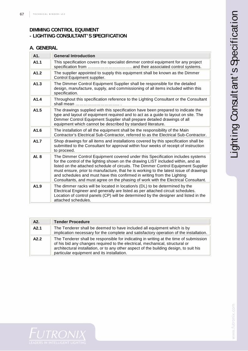
T E C H N I C A L B I N D E R ~ v1.267
DIMMING CONTROL EQUIMENT- LIGHTING CONSULTANT’S SPECIFICATION
A. GENERALA1. General Introduction A1.1 This specification covers the specialist dimmer control equipment for any project
specification from ………………………….. and their associated control systems. A1.2 The supplier appointed to supply this equipment shall be known as the Dimmer
Control Equipment supplier. A1.3 The Dimmer Control Equipment Supplier shall be responsible for the detailed
design, manufacture, supply, and commissioning of all items included within this specification.
A1.4 Throughout this specification reference to the Lighting Consultant or the Consultant shall mean ………………………….. .
A1.5 The drawings supplied with this specification have been prepared to indicate the type and layout of equipment required and to act as a guide to layout on site. The Dimmer Control Equipment Supplier shall prepare detailed drawings of all equipment which cannot be described by standard literature.
A1.6 The installation of all the equipment shall be the responsibility of the Main Contractor’s Electrical Sub-Contractor, referred to as the Electrical Sub-Contractor.
A1.7 Shop drawings for all items and installations covered by this specification shall be submitted to the Consultant for approval within four weeks of receipt of instruction to proceed.
Al. 8 The Dimmer Control Equipment covered under this Specification includes systems for the control of the lighting shown on the drawing LIST included within, and as listed on the attached schedule of circuits. The Dimmer Control Equipment Supplier must ensure, prior to manufacture, that he is working to the latest issue of drawings and schedules and must have this confirmed in writing from the Lighting Consultants, and must agree on the phasing of work with the Electrical Consultant.
A1.9 The dimmer racks will be located in location/s (DL) to be determined by the Electrical Engineer and generally are listed as per attached circuit schedules. Location of control panels (CP) will be determined by the designer and listed in the attached schedules.
A2. Tender Procedure A2.1 The Tenderer shall be deemed to have included all equipment which is by
implication necessary for the complete and satisfactory operation of the installation. A2.2 The Tenderer shall be responsible for indicating in writing at the time of submission
of his bid any changes required to the electrical, mechanical, structural or architectural installation, or to any other aspect of the building design, to suit his particular equipment and its installation.
Ligh
ting
Con
sult
ant’
s Sp
ecif
icat
ion
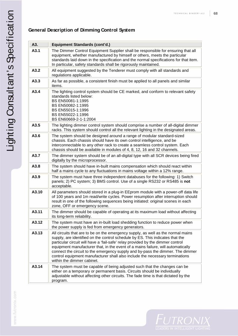
68
CO
MPA
NY
PR
OFI
LET E C H N I C A L B I N D E R ~ v1.2 68
General Description of Dimming Control System
Ligh
ting
Con
sult
ant’
s Sp
ecif
icat
ion
A3. Equipment Standards (cont’d.) A3.1 The Dimmer Control Equipment Supplier shall be responsible for ensuring that all
equipment, whether manufactured by himself or others, meets the particular standards laid down in the specification and the normal specifications for that item. In particular, safety standards shall be rigorously maintained.
A3.2 All equipment suggested by the Tenderer must comply with all standards and regulations applicable.
A3.3 As far as possible, a consistent finish must be applied to all panels and similar items.
A3.4 The lighting control system should be CE marked, and conform to relevant safety standards listed below: BS EN50081-1:1995 BS EN50082-1:1995 BS EN55015-1:1996 BS EN55022-1:1996 BS EN60669-2-1-1:2004
A3.5 The lighting dimmer control system should comprise a number of all-digital dimmer racks. This system should control all the relevant lighting in the designated areas.
A3.6 The system should be designed around a range of modular standard-sized chassis. Each chassis should have its own control intelligence, and be interconnectable to any other rack to create a seamless control system. Each chassis should be available in modules of 4, 8, 12, 16 and 32 channels.
A3.7 The dimmer system should be of an all-digital type with all SCR devices being fired digitally by the microprocessor.
A3.8 The system should have in-built mains compensation which should react within half a mains cycle to any fluctuations in mains voltage within a 12% range.
A3.9 The system must have three independent databuses for the following: 1) Switch panels; 2) PC system; 3) BMS control. Use of a single RS232 or RS485 is not acceptable.
A3.10 All parameters should stored in a plug-in EEprom module with a power-off data life of 100 years and 1m read/write cycles. Power resumption after interruption should result in one of the following sequences being initiated: original scenes in each zone, OFF or emergency scene.
A3.11 The dimmer should be capable of operating at its maximum load without affecting its long-term reliability.
A3.12 The system must have an in-built load shedding function to reduce power when the power supply is fed from emergency generators.
A3.13 All circuits that are to be on the emergency supply, as well as the normal mains supply, are identified on the control schedule by ES. This indicates that the particular circuit will have a ‘fail-safe’ relay provided by the dimmer control equipment manufacturer that, in the event of a mains failure, will automatically connect the circuit to the emergency supply and by-pass the dimmer. The dimmer control equipment manufacturer shall also include the necessary terminations within the dimmer cabinet.
A3.14 The system must be capable of being adjusted such that the changes can be either on a temporary or permanent basis. Circuits should be individually adjustable without affecting other circuits. The fade time is that dictated by the program.
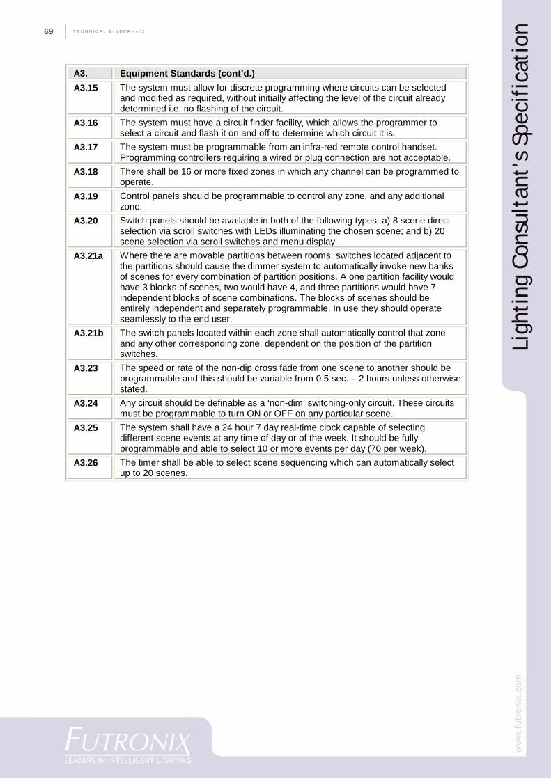
T E C H N I C A L B I N D E R ~ v1.269
Ligh
ting
Con
sult
ant’
s Sp
ecif
icat
ion
A3. Equipment Standards (cont’d.) A3.15 The system must allow for discrete programming where circuits can be selected
and modified as required, without initially affecting the level of the circuit already determined i.e. no flashing of the circuit.
A3.16 The system must have a circuit finder facility, which allows the programmer to select a circuit and flash it on and off to determine which circuit it is.
A3.17 The system must be programmable from an infra-red remote control handset. Programming controllers requiring a wired or plug connection are not acceptable.
A3.18 There shall be 16 or more fixed zones in which any channel can be programmed to operate.
A3.19 Control panels should be programmable to control any zone, and any additional zone.
A3.20 Switch panels should be available in both of the following types: a) 8 scene direct selection via scroll switches with LEDs illuminating the chosen scene; and b) 20 scene selection via scroll switches and menu display.
A3.21a Where there are movable partitions between rooms, switches located adjacent to the partitions should cause the dimmer system to automatically invoke new banks of scenes for every combination of partition positions. A one partition facility would have 3 blocks of scenes, two would have 4, and three partitions would have 7 independent blocks of scene combinations. The blocks of scenes should be entirely independent and separately programmable. In use they should operate seamlessly to the end user.
A3.21b The switch panels located within each zone shall automatically control that zone and any other corresponding zone, dependent on the position of the partition switches.
A3.23 The speed or rate of the non-dip cross fade from one scene to another should be programmable and this should be variable from 0.5 sec. – 2 hours unless otherwise stated.
A3.24 Any circuit should be definable as a ‘non-dim’ switching-only circuit. These circuits must be programmable to turn ON or OFF on any particular scene.
A3.25 The system shall have a 24 hour 7 day real-time clock capable of selecting different scene events at any time of day or of the week. It should be fully programmable and able to select 10 or more events per day (70 per week).
A3.26 The timer shall be able to select scene sequencing which can automatically select up to 20 scenes.
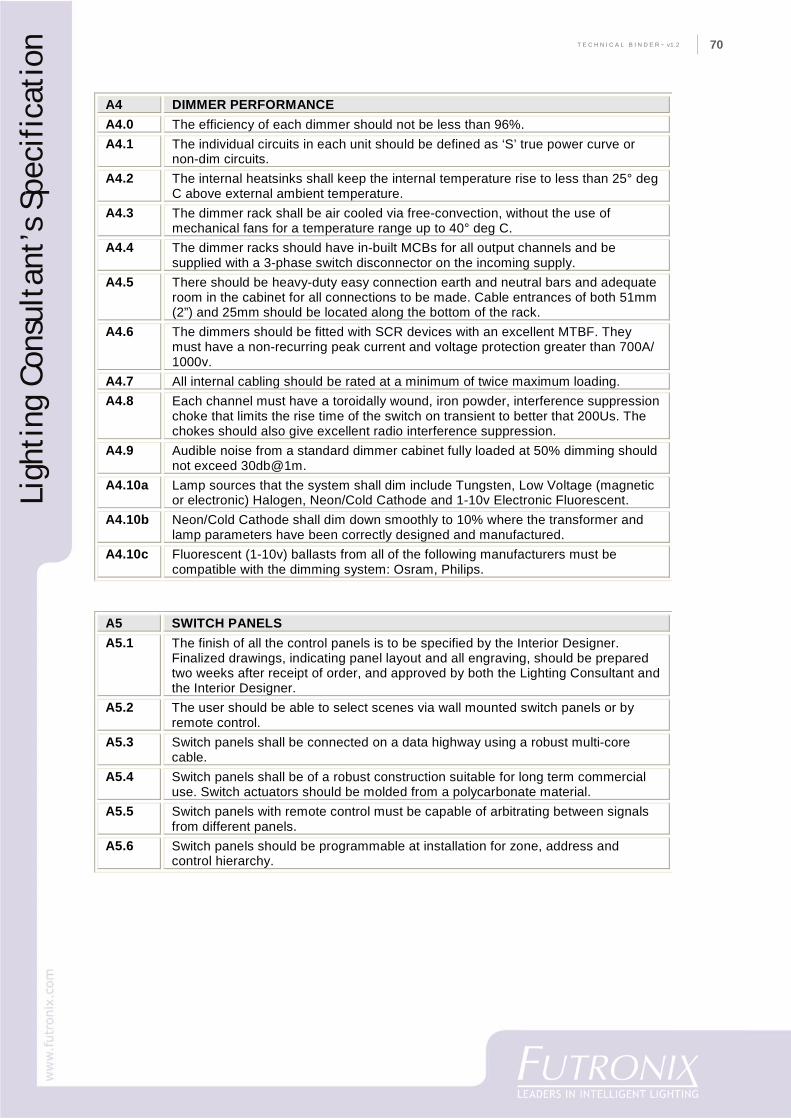
70
CO
MPA
NY
PR
OFI
LET E C H N I C A L B I N D E R ~ v1.2 70
A4 DIMMER PERFORMANCE A4.0 The efficiency of each dimmer should not be less than 96%. A4.1 The individual circuits in each unit should be defined as ‘S’ true power curve or
non-dim circuits. A4.2 The internal heatsinks shall keep the internal temperature rise to less than 25° deg
C above external ambient temperature. A4.3 The dimmer rack shall be air cooled via free-convection, without the use of
mechanical fans for a temperature range up to 40° deg C. A4.4 The dimmer racks should have in-built MCBs for all output channels and be
supplied with a 3-phase switch disconnector on the incoming supply. A4.5 There should be heavy-duty easy connection earth and neutral bars and adequate
room in the cabinet for all connections to be made. Cable entrances of both 51mm (2”) and 25mm should be located along the bottom of the rack.
A4.6 The dimmers should be fitted with SCR devices with an excellent MTBF. They must have a non-recurring peak current and voltage protection greater than 700A/ 1000v.
A4.7 All internal cabling should be rated at a minimum of twice maximum loading. A4.8 Each channel must have a toroidally wound, iron powder, interference suppression
choke that limits the rise time of the switch on transient to better that 200Us. The chokes should also give excellent radio interference suppression.
A4.9 Audible noise from a standard dimmer cabinet fully loaded at 50% dimming should not exceed 30db@1m.
A4.10a Lamp sources that the system shall dim include Tungsten, Low Voltage (magnetic or electronic) Halogen, Neon/Cold Cathode and 1-10v Electronic Fluorescent.
A4.10b Neon/Cold Cathode shall dim down smoothly to 10% where the transformer and lamp parameters have been correctly designed and manufactured.
A4.10c Fluorescent (1-10v) ballasts from all of the following manufacturers must be compatible with the dimming system: Osram, Philips.
A5 SWITCH PANELS A5.1 The finish of all the control panels is to be specified by the Interior Designer.
Finalized drawings, indicating panel layout and all engraving, should be prepared two weeks after receipt of order, and approved by both the Lighting Consultant and the Interior Designer.
A5.2 The user should be able to select scenes via wall mounted switch panels or by remote control.
A5.3 Switch panels shall be connected on a data highway using a robust multi-core cable.
A5.4 Switch panels shall be of a robust construction suitable for long term commercial use. Switch actuators should be molded from a polycarbonate material.
A5.5 Switch panels with remote control must be capable of arbitrating between signals from different panels.
A5.6 Switch panels should be programmable at installation for zone, address and control hierarchy.
Ligh
ting
Con
sult
ant’
s Sp
ecif
icat
ion
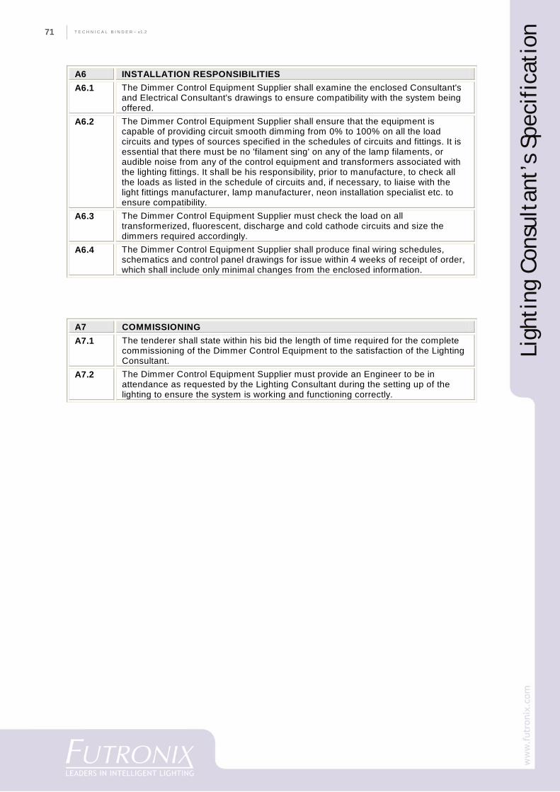
T E C H N I C A L B I N D E R ~ v1.271
A6 INSTALLATION RESPONSIBILITIES A6.1 The Dimmer Control Equipment Supplier shall examine the enclosed Consultant's
and Electrical Consultant's drawings to ensure compatibility with the system being offered.
A6.2 The Dimmer Control Equipment Supplier shall ensure that the equipment is capable of providing circuit smooth dimming from 0% to 100% on all the load circuits and types of sources specified in the schedules of circuits and fittings. It is essential that there must be no 'filament sing' on any of the lamp filaments, or audible noise from any of the control equipment and transformers associated with the lighting fittings. It shall be his responsibility, prior to manufacture, to check all the loads as listed in the schedule of circuits and, if necessary, to liaise with the light fittings manufacturer, lamp manufacturer, neon installation specialist etc. to ensure compatibility.
A6.3 The Dimmer Control Equipment Supplier must check the load on all transformerized, fluorescent, discharge and cold cathode circuits and size the dimmers required accordingly.
A6.4 The Dimmer Control Equipment Supplier shall produce final wiring schedules, schematics and control panel drawings for issue within 4 weeks of receipt of order, which shall include only minimal changes from the enclosed information.
A7 COMMISSIONING A7.1 The tenderer shall state within his bid the length of time required for the complete
commissioning of the Dimmer Control Equipment to the satisfaction of the Lighting Consultant.
A7.2 The Dimmer Control Equipment Supplier must provide an Engineer to be in attendance as requested by the Lighting Consultant during the setting up of the lighting to ensure the system is working and functioning correctly.
Ligh
ting
Con
sult
ant’
s Sp
ecif
icat
ion
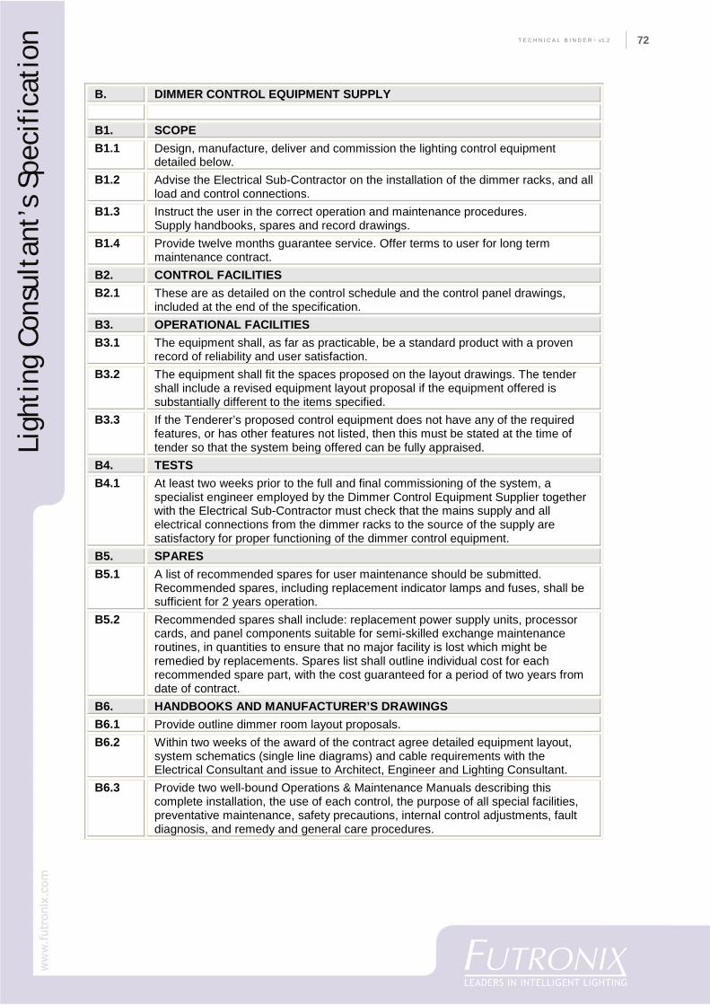
72
CO
MPA
NY
PR
OFI
LET E C H N I C A L B I N D E R ~ v1.2 72
B. DIMMER CONTROL EQUIPMENT SUPPLY B1. SCOPE B1.1 Design, manufacture, deliver and commission the lighting control equipment
detailed below. B1.2 Advise the Electrical Sub-Contractor on the installation of the dimmer racks, and all
load and control connections. B1.3 Instruct the user in the correct operation and maintenance procedures.
Supply handbooks, spares and record drawings. B1.4 Provide twelve months guarantee service. Offer terms to user for long term
maintenance contract. B2. CONTROL FACILITIES B2.1 These are as detailed on the control schedule and the control panel drawings,
included at the end of the specification. B3. OPERATIONAL FACILITIES B3.1 The equipment shall, as far as practicable, be a standard product with a proven
record of reliability and user satisfaction. B3.2 The equipment shall fit the spaces proposed on the layout drawings. The tender
shall include a revised equipment layout proposal if the equipment offered is substantially different to the items specified.
B3.3 If the Tenderer’s proposed control equipment does not have any of the required features, or has other features not listed, then this must be stated at the time of tender so that the system being offered can be fully appraised.
B4. TESTS B4.1 At least two weeks prior to the full and final commissioning of the system, a
specialist engineer employed by the Dimmer Control Equipment Supplier together with the Electrical Sub-Contractor must check that the mains supply and all electrical connections from the dimmer racks to the source of the supply are satisfactory for proper functioning of the dimmer control equipment.
B5. SPARES B5.1 A list of recommended spares for user maintenance should be submitted.
Recommended spares, including replacement indicator lamps and fuses, shall be sufficient for 2 years operation.
B5.2 Recommended spares shall include: replacement power supply units, processor cards, and panel components suitable for semi-skilled exchange maintenance routines, in quantities to ensure that no major facility is lost which might be remedied by replacements. Spares list shall outline individual cost for each recommended spare part, with the cost guaranteed for a period of two years from date of contract.
B6. HANDBOOKS AND MANUFACTURER’S DRAWINGS B6.1 Provide outline dimmer room layout proposals. B6.2 Within two weeks of the award of the contract agree detailed equipment layout,
system schematics (single line diagrams) and cable requirements with the Electrical Consultant and issue to Architect, Engineer and Lighting Consultant.
B6.3 Provide two well-bound Operations & Maintenance Manuals describing this complete installation, the use of each control, the purpose of all special facilities, preventative maintenance, safety precautions, internal control adjustments, fault diagnosis, and remedy and general care procedures.
Ligh
ting
Con
sult
ant’
s Sp
ecif
icat
ion
T E C H N I C A L B I N D E R ~ v1.273
Ligh
ting
Con
trol
Sys
tem
s
Lighting Control Systems
(Example)
Recommendationsfor
Luxury Residences
74
CO
MPA
NY
PR
OFI
LET E C H N I C A L B I N D E R ~ v1.2 74
Lighting Control Systems
(Example)
Recommendations for Luxury Residences
GeneralIt is recommended that a lighting control system be installed in order to provide convenience andsimplicity of operation, replacing a conventional fixed wired layout with a software based system,adaptable to the owner’s current and future requirements.
The lighting control system should use a smart switch panel to control entire groups of lights locatedin the same room or throughout the house, replacing rows of single-light dimmers and switches, andallowing the user to select combinations of lighting levels called ‘scenes’ with one key stroke. Operationaffords benefits for every major room in the residence and grounds.
FunctionalityIt is indicated that the residence is a luxury ‘resort style’, encompassing a cluster of main buildingsand accommodation in a ‘garden/pool’ setting. Adjacent open kitchen/bar/veranda areas may bedivided into zones for dining, relaxation and entertainment. Each of these functions will likely requiredifferent types and levels of lighting, selectable from a number of conveniently located switchpoints.The system should therefore feature multi-channel dimming and switching of lighting from multi-point locations.
It is recommended that: 1) a master switchpanel is located by the Front Entrance where owners canselect a ‘welcome’ scene or turn on security lighting when leaving home; 2) a central switch panel islocated in the Hallway opposite the Living Hall; 3) the switch panel in the Living Hall should have aremote control option and temporary settings for entertaining; 4) dual zone switch panels are locatedin the kitchen area to control inside and outside areas; 5) (optionally) a master switchplate is locatedin the Main Bedroom so lighting in the house can be dimmed or turned off from one location beforegoing to bed, leaving pre-programmed security lights switched on if required.
OperationA ‘scene-based’ system is indicated, instead of simple raise/lower faders, because the lighting levelscan be customized to the user’s preferences for different tasks.
The lighting control system should provide multi-location dimming of circuits in different rooms orareas, using pre-programmed scenes which gently fade from one scene to the next so the change issubtle to the eye. Area lighting can then be transformed for ambient or mood lighting and architecturalillumination. In use, scenes should be recalled at the touch of a button on the switch panel or remotecontrol handset. There should be at least 20 scenes available per room/area. Scenes should be initiallyprogrammed by the commissioning engineer in conjunction with the owner and/or designer. If required,further re-programming by the customer should be possible, using the remote control or optional PC.
ExteriorThe lighting control system should include mixed dimming and relay switching options for controllingdimmable and non-dim architectural and landscape lighting as specified by the designer. Relay switchingunits should also be able to control water and garden features, exterior signage, and main entranceillumination.
Switch panelsLocalized user operation should be from a range of attractive, robust solid metal switch plates,available in finishes to complement the decor. Switches should feature an optional display and IR
Ligh
ting
Con
trol
Sys
tem
s
T E C H N I C A L B I N D E R ~ v1.275
Curtains & blindsIf required by owner there should be the optionto control curtains and blinds as specified bythe designer.
EquipmentControl equipment should be MCB protected forsafety, and to isolate individual circuits formaintenance purposes. It should draw its’ powerfrom the main distribution box via correctlyrated circuit breakers.
Control equipment should be wall-mounted outof sight in an electrical cupboard, store room,garage or similar - as indicated by the consultant.
All lighting to be operated by the control systemis simply wired back to central points where theequipment is located. Switch panel controlconnections should be daisy-chained to eachswitch location for easy installation.
InstallationElectrical cabling installation should beelectrician-friendly, and of a comparable costto conventional wiring. The system shouldoperate reliably on the local power supplysystem and where necessary (at extra cost)integrate into the emergency power supplysystem as specified by the designer.
Enhanced control (option)For enhanced centralised control the systemshould have industry standard databusconnectivity for connecting directly to a colorTouchScreen, or to a PC or laptop. Thetouchscreen should offer features such asprogramming lighting scenes, raising and
lowering lighting circuit levels, and saving systemchanges.
Quality & DurabilityThe system should be of an all-digital design andcommercial build quality to ensure reliable,trouble-free operation. It should be easy toinstall, highly reliable, and be able to cope withlamp wattage changes, short-circuits, overloadsand wiring alterations.
The vendor shall have at least 10 years ofcontinuous operation and a proven track recordin supplying similar equipment within the region.
WarrantyThe manufacturer should provide a 2-yearequipment warranty from the date ofmanufacture, subject to the equipment beinginstalled and operated within the manufacturer’sproduct specifications.
Ligh
ting
Con
trol
Sys
tem
s
76
CO
MPA
NY
PR
OFI
LET E C H N I C A L B I N D E R ~ v1.2 76
FAQ
- L
ight
ing
Cont
rol S
yste
ms
FAQLighting Control Systems
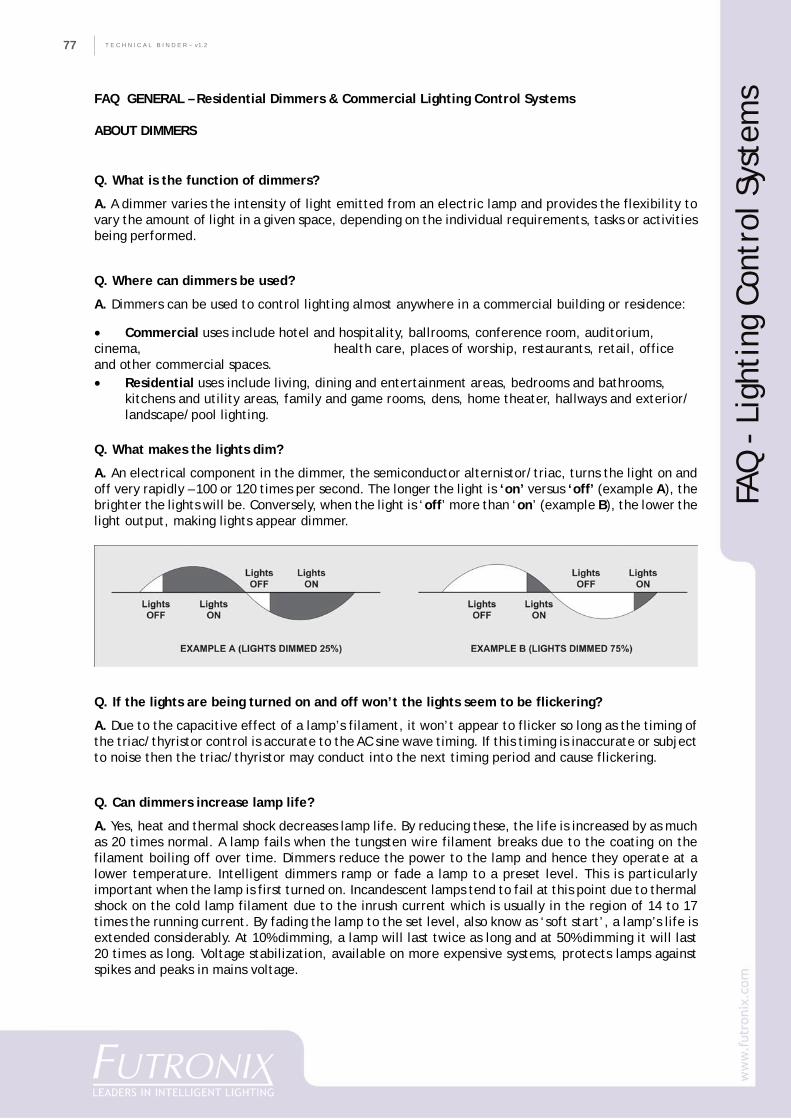
T E C H N I C A L B I N D E R ~ v1.277
FAQ GENERAL – Residential Dimmers & Commercial Lighting Control Systems
ABOUT DIMMERS
Q. What is the function of dimmers?
A. A dimmer varies the intensity of light emitted from an electric lamp and provides the flexibility tovary the amount of light in a given space, depending on the individual requirements, tasks or activitiesbeing performed.
Q. Where can dimmers be used?
A. Dimmers can be used to control lighting almost anywhere in a commercial building or residence:
• Commercial uses include hotel and hospitality, ballrooms, conference room, auditorium,cinema, health care, places of worship, restaurants, retail, officeand other commercial spaces.• Residential uses include living, dining and entertainment areas, bedrooms and bathrooms,
kitchens and utility areas, family and game rooms, dens, home theater, hallways and exterior/landscape/pool lighting.
Q. What makes the lights dim?
A. An electrical component in the dimmer, the semiconductor alternistor/triac, turns the light on andoff very rapidly – 100 or 120 times per second. The longer the light is ‘on’ versus ‘off’ (example A), thebrighter the lights will be. Conversely, when the light is ‘off’ more than ‘on’ (example B), the lower thelight output, making lights appear dimmer.
Q. If the lights are being turned on and off won’t the lights seem to be flickering?
A. Due to the capacitive effect of a lamp’s filament, it won’t appear to flicker so long as the timing ofthe triac/thyristor control is accurate to the AC sine wave timing. If this timing is inaccurate or subjectto noise then the triac/thyristor may conduct into the next timing period and cause flickering.
Q. Can dimmers increase lamp life?
A. Yes, heat and thermal shock decreases lamp life. By reducing these, the life is increased by as muchas 20 times normal. A lamp fails when the tungsten wire filament breaks due to the coating on thefilament boiling off over time. Dimmers reduce the power to the lamp and hence they operate at alower temperature. Intelligent dimmers ramp or fade a lamp to a preset level. This is particularlyimportant when the lamp is first turned on. Incandescent lamps tend to fail at this point due to thermalshock on the cold lamp filament due to the inrush current which is usually in the region of 14 to 17times the running current. By fading the lamp to the set level, also know as ‘soft start’, a lamp’s life isextended considerably. At 10% dimming, a lamp will last twice as long and at 50% dimming it will last20 times as long. Voltage stabilization, available on more expensive systems, protects lamps againstspikes and peaks in mains voltage.
FAQ
- L
ight
ing
Cont
rol S
yste
ms
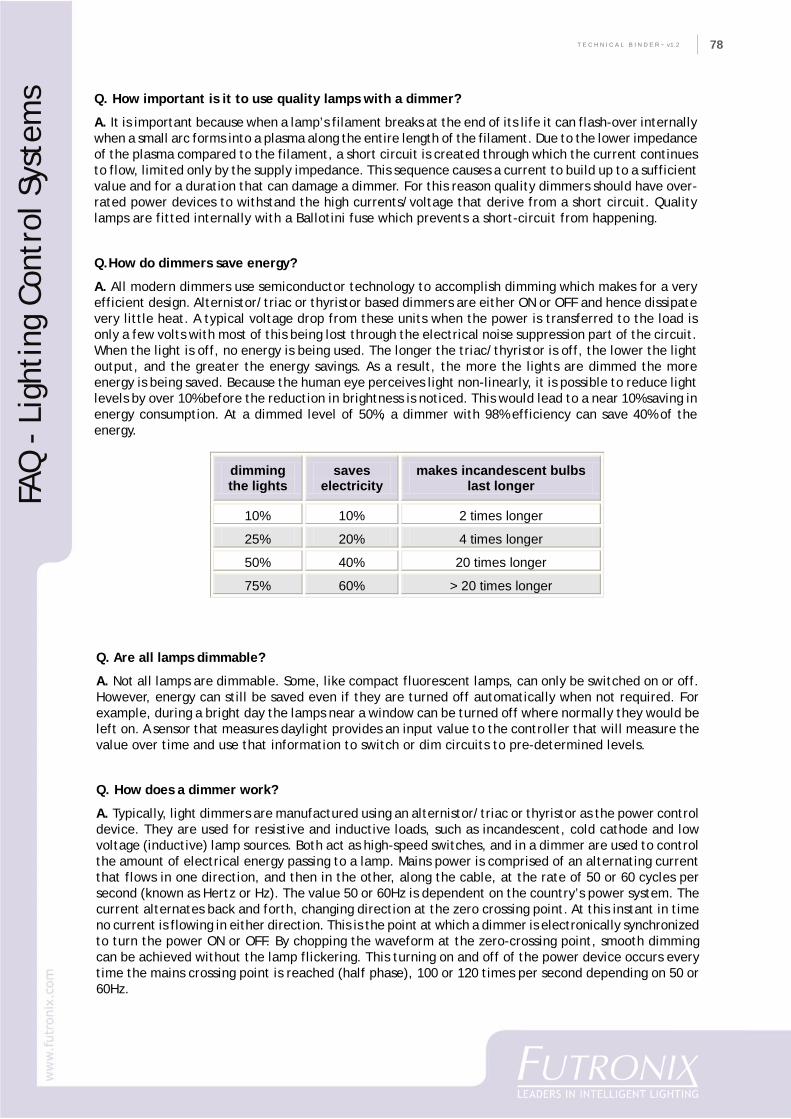
78
CO
MPA
NY
PR
OFI
LET E C H N I C A L B I N D E R ~ v1.2 78
Q. How important is it to use quality lamps with a dimmer?
A. It is important because when a lamp’s filament breaks at the end of its life it can flash-over internallywhen a small arc forms into a plasma along the entire length of the filament. Due to the lower impedanceof the plasma compared to the filament, a short circuit is created through which the current continuesto flow, limited only by the supply impedance. This sequence causes a current to build up to a sufficientvalue and for a duration that can damage a dimmer. For this reason quality dimmers should have over-rated power devices to withstand the high currents/voltage that derive from a short circuit. Qualitylamps are fitted internally with a Ballotini fuse which prevents a short-circuit from happening.
Q.How do dimmers save energy?
A. All modern dimmers use semiconductor technology to accomplish dimming which makes for a veryefficient design. Alternistor/triac or thyristor based dimmers are either ON or OFF and hence dissipatevery little heat. A typical voltage drop from these units when the power is transferred to the load isonly a few volts with most of this being lost through the electrical noise suppression part of the circuit.When the light is off, no energy is being used. The longer the triac/thyristor is off, the lower the lightoutput, and the greater the energy savings. As a result, the more the lights are dimmed the moreenergy is being saved. Because the human eye perceives light non-linearly, it is possible to reduce lightlevels by over 10% before the reduction in brightness is noticed. This would lead to a near 10% saving inenergy consumption. At a dimmed level of 50%, a dimmer with 98% efficiency can save 40% of theenergy.
dimming the lights
saves electricity
makes incandescent bulbs last longer
10% 10% 2 times longer
25% 20% 4 times longer
50% 40% 20 times longer
75% 60% > 20 times longer
Q. Are all lamps dimmable?
A. Not all lamps are dimmable. Some, like compact fluorescent lamps, can only be switched on or off.However, energy can still be saved even if they are turned off automatically when not required. Forexample, during a bright day the lamps near a window can be turned off where normally they would beleft on. A sensor that measures daylight provides an input value to the controller that will measure thevalue over time and use that information to switch or dim circuits to pre-determined levels.
Q. How does a dimmer work?
A. Typically, light dimmers are manufactured using an alternistor/triac or thyristor as the power controldevice. They are used for resistive and inductive loads, such as incandescent, cold cathode and lowvoltage (inductive) lamp sources. Both act as high-speed switches, and in a dimmer are used to controlthe amount of electrical energy passing to a lamp. Mains power is comprised of an alternating currentthat flows in one direction, and then in the other, along the cable, at the rate of 50 or 60 cycles persecond (known as Hertz or Hz). The value 50 or 60Hz is dependent on the country’s power system. Thecurrent alternates back and forth, changing direction at the zero crossing point. At this instant in timeno current is flowing in either direction. This is the point at which a dimmer is electronically synchronizedto turn the power ON or OFF. By chopping the waveform at the zero-crossing point, smooth dimmingcan be achieved without the lamp flickering. This turning on and off of the power device occurs everytime the mains crossing point is reached (half phase), 100 or 120 times per second depending on 50 or60Hz.
FAQ
- L
ight
ing
Cont
rol S
yste
ms

T E C H N I C A L B I N D E R ~ v1.279
A thyristor is a uni-directional device and hence, because AC power flows in both directions, two areneeded. A triac is a bi-directional device, and therefore only one is needed. An electronic circuitdetermines the point in time at which they turn ON (conduct). The ON state continues until the nextzero-crossing point, at which point the device turns itself OFF. The electronic circuit then provides adelay, which equates to the dimness of the lamp, before turning the control device back on. The slightcapacitance of the load filters the chopped waveform resulting in a smooth light output.
Some controllers use a microprocessor control, with the above timing function being handled by ananalogue circuit. More sophisticated systems, called digital dimmers, operate the switching directfrom a microprocessor. This has the advantage of greater reliability, quieter operation, lower cost andsmaller units.
Q. What different types of dimmer are there?
A. Essentially there are three types of dimmer: LEADING EDGE, LAGGING EDGE and SINUSOIDAL.Leading Edge (as described above) delays the ‘turn-on’ time from the zero crossing point; Lagging Edgeturns off after the desired time period has passed; and Sinusoidal alters the amplitude of the sinusoidalwave form. Leading Edge uses alternistor/triacs or thyristors while Lagging Edge uses transistors, as doSinusoidal dimmers.
Q. Which of the three types of dimmer is better?
A. Sinusoidal is the most sophisticated, but also the most expensive and bulky. Trailing Edge is compatiblewith electronic capacitive transformers. Both of the above use IGBT transistors, which are not robustdevices, and must be continually monitored by the microprocessor to prevent damage. They areparticularly vulnerable to difficult mains power conditions and shouldn’t be used with wire woundtransformers due to their susceptibility to back-EMF. Leading Edge is the most accepted method ofdimming and also the most robust if alternistors are used.
Q. What is the difference between triac, thyristor and alternistor dimmers?
A. Triacs and thyristors are similar components: A triac is essentially two thyristors combined in onepackage:
• Thyristors tend to be more expensive but more robust.• Triacs have the advantage that they are less likely to ‘half wave’ on failure.• Alternistors are a perfectly matched set of two thyristors (SCRs wired inverse parallel i.e. back-to- back). This chip construction provides two electrically separate SCR structures, providingenhanced performance characteristics, and can be used with highly inductive loads –often used in motor drive applications.
Q. What is an inductive load?
A. Mains voltage incandescent lamps have a resistive characteristic; the voltage and current waveformsare almost identical. On the other hand, a wire wound transformer is an inductive load and the currenttends to lag behind the voltage.
Q. Do I need a special dimmer for transformer loads?
A. A quality leading-edge inductive dimmer should be used which is fully digital and has a symmetricaloutput voltage waveform. The majority of ‘economy’ domestic dimmers do not guarantee that theoutput waveform is symmetrical, and therefore may cause damage to the transformers.
FAQ
- L
ight
ing
Cont
rol S
yste
ms
80
CO
MPA
NY
PR
OFI
LET E C H N I C A L B I N D E R ~ v1.2 80
Q. Do dimmers get warm and why?
A. Yes. Feeling warm to the touch is a normal phenomenon and common to all dimmers. All moderndimmers use semiconductor technology and during normal operation they generate heat. A semiconductordimmer is roughly 98% efficient – 2% of the power is dissipated as heat, causing the dimmer to feelwarm to the touch. The closer a dimmer is run to full output the higher the current flow and hence themore heat will be generated. The components that Futronix use employ the highest standard coolingmethodologies, meaning the units stay cooler than other models for their rating.
SCENE SETTING & ZONES
Q. What is a Lighting ‘Zone’?
A. A lighting zone is a room or area that one or more circuits of lights resides in.
Q. What is a Lighting ‘Scene’?
A. A lighting ‘scene’ is when two or more lighting circuits in a room fade to predefined lighting levels.Each circuit of lighting can be pre-programmed to a different level of brightness. All of these pre-setlevels combined are stored as a ‘scene’ which can best be thought of as being a complete ‘look’ of aroom or area. Once set up, scenes should be easily recalled by the user from wall mounted switchpanels, infra-red remote controls, or touch screen. They can also be recalled automatically by timeclock, or according to occupancy. Once a new scene is selected the lighting will fade to the new set oflevels at the pre-determined fade rate.
Q. How are lighting ‘scenes’ programmed?
A. Programming of lighting scenes is done using either:
• hand-held remote control unit• dimmer control panel buttons• color touch screen• PC or laptop which is removed once the programming is completed, or a dedicated computer for
operation.A lighting control system should feature an easy way for an end user to re-program basic scenesusing a hand-held remote control unit without the need to call in an expert.
Q. How are lighting ‘scenes’ selected?
A. Scenes can be selected from a push-button control panel, wall-mounted at a logical position withina room. In many applications there will be several controls operating in parallel as well as switchpanels; there may be a time clock, remote control, LCD touch screen, central PC controller, PE/PIRunits as well as Building Management Systems.
Q. How many scenes do I need?
A. A typical number of lighting scenes in a ballroom might be 20, whereas in a home theater it could be8 scenes. Overall, the total memory should be around 128 scenes.
FAQ
- L
ight
ing
Cont
rol S
yste
ms
T E C H N I C A L B I N D E R ~ v1.281
Q. Where are the scenes stored?
A. Scenes should be stored in a secure removable memory module (EEprom or Flash) so that in theevent of a memory failure it can be exchanged. Most memory modules have a life span of 10 years ormore.
Q. What is a Fade Rate?
A. A fade rate is the time taken for a circuit to change from one level of brightness to another one.
Q. Can a dimmer fade smoothly?
A. In sophisticated systems the computer should dynamically recalculate the fading time andcorresponding fade rate of each circuit, so as to reach the end point for all circuit transitions at thesame time, thus creating a smooth blending of light. A more basic system will just fade a single circuitat its own set rate – without taking into consideration the other circuits that are part of the samescene.
Q. Why do some dimmers cause flicker?
A. In order to fade smoothly a dimmer must have good timing accuracy and a high number of digitalsteps. A good test of a dimmer is to look at a chandelier from the corner of your eye (using fasterperipheral vision); while it is dimming you should not be able to notice any discernible stepping orflickering.
Q. What is a Touch Screen?
A. An LCD touch screen is a graphical user interface to lighting systems and other controls, providing avery flexible and intuitive method of operating and programming the lighting control system. It offersmultiple control functions that have many advantages over conventional static control panels. It isideal where a user may need simple control, while an installer needs access to more complex controland programming functions. Typical uses are selecting scenes, changing circuit levels, programming,setting the time clock, and other functions.
Q. What are typical features of a Touch Screen?
A. Typical Touch Screen features can include:
• virtual slider for manually changing circuit levels• scene select buttons• system master control• astronomical time clock• customizable welcome menu• access protection• programming menus• Help pages.
FAQ
- L
ight
ing
Cont
rol S
yste
ms

82
CO
MPA
NY
PR
OFI
LET E C H N I C A L B I N D E R ~ v1.2 82
TYPES OF LAMPS, TRANSFORMERS AND BALLASTS
Q. What light sources can be controlled by dimmers?
A. A quality dimmer can control:
DIMMABLE LIGHT SOURCES• tungsten• tungsten halogen• 1-10v regulation HF fluorescent ballasts (with 1-10v converter card)• PL/T fluorescent (dimmable ballast)• neon/cold cathode
SWITCHABLE LIGHT SOURCES• compact fluorescent• PL fluorescent• metal halide• sodium• mercury
Q. How do I know the size of dimmer I need?
A. To calculate, simply multiply the wattage of each lamp by the number of lamps. This gives the totalwattage on that circuit. The dimmer should match or exceed that wattage per circuit (dimmer channel).
Q. What kind of dimmer should be used to control low voltage lighting?
A. If low voltage lighting is used then a dimmer should be an inductive dimmer type. There are twotypes of transformer: electronic and magnetic.
Q. What are the concerns with electronic transformers?
A. Unlike wire wound transformers, which by their very nature are dimmable, electronic transformersmay induce problems and care must be taken when selecting electronic transformers to ensurecompatibility with dimmers in a control system. Some electronic transformers are non-dim types.These transformers should not be connected to a dimming controller unless it is configured as a switchedoutput, or damage to the transformer may occur.
Q. How do I tell magnetic and electronic low-voltage tranformers apart?
A. Hint: the transformer type can often be determined by the transformer’s weight.Magnetic (core and coil, toroidal) transformers are often heavy for their size.Electronic (solid-state) transformers tend to be smaller and are often light for their size.
Q. If one dimmer needs to control both mains voltage lamps AND a low voltage lighting system,what kind of dimmer should be used to control this combination?
A. Don’t mix different types of lamps on the same circuit as its likely their dimming brightness willdiffer. Instead, use separate circuits on a multi-channel dimmer for each circuit.
Q. Is it best to use one large transformer or smaller multiple ones?
A. When dimming low voltage lamps, one transformer per lamp should be used instead of one largetransformer, so that if a transformer fails only a single lamp is extinguished. Transformers can be easilychanged, as being smaller they can be fitted through the same ceiling cut-out as the light fitting. Largetransformers are also more prone to noise and nuisance tripping if the voltage drops for any reason.
FAQ
- L
ight
ing
Cont
rol S
yste
ms
T E C H N I C A L B I N D E R ~ v1.283
Q. Why do light bulbs buzz or hum sometimes?
A. Occasionally, lamps may generate noise when dimmed. Light bulb hum is caused by vibration of thelamp filament as the dimmer rapidly switches the lamp on. Lamp buzz, if it occurs, is generally noisiestat the mid-range (50%) dimming level. Inexpensive household lamps are often the culprit because thefilament is only supported at the ends. The ‘sing’ occurs when we turn the power on and off 100/120times a second, pushing the filament back and forth from rest to positive to negative. A quality digitaldimmer with high accuracy and good noise suppression should not produce much discernable noise witha good lamp and fitting.
Q. How sensitive is the system to surges?
A. The dimmer should be internally protected to withstand surges up to 6Kv. If the system is modularand some system components fail as a result of a severe power surge, the function of other componentsand of the system as a whole should not be affected. In a lightning-prone area, it is always recommendedto add local surge protection before the dimmer, as electronic components can not survive a direct ornear lightning strike.
Q. What happens to the system if electrical power is cut due to a storm?
A. During a loss of power, the system should retain all the programming information in internal memory(for up to 10 years). When power is restored, the system will automatically return all settings to theirlast state before power was lost. The system data should be stored in a secure removable memorymodule (EEprom or Flash) so that in the event of a system failure it can be simply exchanged withoutthe need to reprogram the system.
Q. How do you dim fluorescents?
A. To dim fluorescent lamps, an electronically-dimmable ballast must be used. This should be of thecorrect wattage for the lamp being controlled. The dimming range of these lamps is due to the ballast’scapabilities rather than the dimmer’s. As a general rule, those lamps with four pins are dimmable.Those lamps with two pins and integral starters are not dimmable.
There are 3 types of dimmable ballasts with different control inputs available:
• The 1-10v dimmable ballast is the most common type preferred due to its lower purchase priceand greater economy. The intensity of the lamp is determined by a control voltage in the range 1-10volts. These are the most economical and most interchangeable, and can be easily replaced at the endof their life. Units do require the mains power supply to be switched on or off.• The second popular ballast is the digital ballast available from Tridonic. These are referred to asDSI ballasts. The primary advantage that these ballasts have over the 1-10 volt units is that they havean internal electronic switch. By using the digital control pair, the power can be switched on/off aspart of a control message. However, standby power consumption of the ballast makes this less efficient.The minimum illuminance is generally 1% but because of a fluorescent’s dimming curve, this is not thatdim.• Finally, there are DALI ballasts. These ballasts offer integral controls and scene setting functions.In practice, the concept requires software setup for each ballast including individual address, scenevalue and Power On level. This means that commissioning or maintaining of installed systems is complexand expensive. Fade rates are also restricted and each network is limited to a maximum of 64 ballasts.Standby power consumption of 7VA is quite high per ballast, and reduces energy efficiency for a wholeinstallation.
All the above types require a pair of cables, one pair for the control signal and the other for the mainspower feed. The control and mains power should always be kept separate. Mains voltage must never beapplied to the control signal terminals or cables.
FAQ
- L
ight
ing
Cont
rol S
yste
ms
84
CO
MPA
NY
PR
OFI
LET E C H N I C A L B I N D E R ~ v1.2 84
Q. What connections are needed with 1-10v ballasts?
A. The dimming controller should provide a dedicated mains switching output per circuit as well asthe 1-10 volt control pair. Due to the switching of high loads, arc-free relay switching controllers arerecommended for this type of application.
Q. Are there any special considerations when dimming fluorescent ballasts?
A. Due to the fact that different type and wattage lamps may have different levels of luminance for agiven input, it is advisable not to mix fixtures with different lamp types on the same dimmer channel.
Q. Can standard ballasts be dimmed?
A. These ballasts are not dimmable, but can be controlled by relay switching controllers.
Q. Can neon/cold cathode lamps be dimmed?
A. Yes. Neon/cold cathode lamps can be dimmed with special dimmers designed to operate on highlyinductive magnetic (core and coil) step-up transformers. A dimming range of 95%-10% should be possible.Cold cathode lighting is common in coffer lighting applications and in signage. It is most useful in areaswhere access for re-lamping is restricted, as the tube life can exceed 80,000 hours.
Q. What is the difference between neon and cold cathode?
A. Neon is a generic term often used to describe all 3 types of lamp. These lamps contain Argon, Neonor Krypton gas depending on the desired color of light. Their ability to be dimmed is dependent on thematerials and construction involved. Transformers, tube diameter, electrodes, gas, manufacturingpractices, age, low temperature, cables and HT wiring connections will all affect the ability of thetube to be dimmed.
For dimming down to a low level, the transformer size should be carefully calculated by the installer.Argon gas-filled tubes are the easiest to dim. Neon tubes can be dimmed over a reduced range. Tubediameter is also significant to performance: the larger the diameter, the better the likely outcome fordimming. Leading Edge dimmers with a high current, inductive load and back-EMF capability are suitablefor dimming cold cathode.
Q. What type of transformer should be used?
A. The transformer should be an electronic or wire wound type approved by the manufacturer fordimming with a Leading Edge dimmer. If using a dimmable electronic transformer, de-rate the dimmerchannel by 10%. If using an iron-core transformer, de-rate the dimmer channel by 60% and ensure thatany power factor correction capacitors are removed. This should be checked carefully, as sometransformers have the power factor correction capacitor fitted inside the transformer casing (oftenembedded inside the resin fill), making it difficult to remove.
If the transformer is an OCP (Open Circuit Protection) type, ensure that it is suitable for dimming, asmany OCP transformers are not. This type of transformer has circuitry that will automatically disconnectthe transformer’s output in the event of a tube breakage.
Q. What type of cable should be used?
A. Cables should NOT be of the braided type. GTO cables between the neon tube electrodes and thetransformer should not be longer than 6 metres, and should be separated from each other by at least100mm. Avoid running cables near metal or in metal conduits. If metal conduit must be used, try to usea non-ferrous alloy type.
FAQ
- L
ight
ing
Cont
rol S
yste
ms
T E C H N I C A L B I N D E R ~ v1.285
Q. Are there any other special considerations?
A. Consideration should be given to reducing capacitance coupling, which results from the electricfield that surrounds every AC current carrying conductor. It has the ability to conduct AC currentthrough air between the tubes, GTO, electronic power supply and any mounting surface. An exampleincludes the dimming or tripping of a lit tube when you grasp it with your hand. Any high voltagewiring, as well as neon tubes, will have capacitance coupling to ground. In extreme cases this cancause neon power supplies with GFI to ‘trip’ due to excess ground fault current or over loading. FalseTripping is a major problem caused by excessive capacitance coupling. Electronic Cross Talk can occurbetween power supplies, tubes, or GTO leads in multi-transformer applications.
Q. Can discharge lamps like metal halide and sodium be controlled?
A. The most economical way is to switch these lamps using arc-free relay/contactor switching. Theyare usually wired in alternate lamp configurations to allow for reduced light levels through switchingcircuits on or off as required. Expensive sine wave dimmers can dim these lamp types down to 40-50%,however there may be some variation in color temperature, and lamp life may be reduced.
When calculating the REAL current for the switching device it is most important NOT to assume thatthe connected load can be calculated by multiplying the lamp wattage by the number of lamps. Forexample, a 150W Metal Halide lamp has 4x the starting current which can last throughout the entirestriking cycle.
Q. Can LED lamps be dimmed?
A. LED lamps for architectural use are either mains voltage or contain a control circuit which is eithera Voltage mode, Current mode or Input Nominal Supply Voltage and Current type. Some LED lamptransformers have a 1-10v control input, and some are mains dimmable. Mains voltage LED fittings thataren’t dimmable may also be connected to a relay controller when simple ON/OFF control is required.
Voltage mode fittings incorporate integral current limiting devices and are designed for direct connectionto a nominal supply voltage. Current mode fittings do not include the facility to limit current andtherefore must be connected to a constant current supply, and rated Input Nominal Supply applies tomulti channel fittings (i.e. RGB) designed for color mixing applications.
Q. Can my lighting control system control my blind/drapes or curtains?
A. Yes, using a compatible relay controller with two-way motorized lockout, it should be possible tocontrol window treatments as part of a lighting scene. A typical application is in home theaters wherethe dimmer automatically closes the blinds and fades the lights with one touch.
Q. Can a lighting control system communicate with other systems such as a HA controller or hometheater touchscreen?
A. Yes. There are widely available optional interfaces to other equipment using infrared (IR) and serial(RS232/485) controls.
FAQ
- L
ight
ing
Cont
rol S
yste
ms
86
CO
MPA
NY
PR
OFI
LET E C H N I C A L B I N D E R ~ v1.2 86
Q. Can I control fan motors with a dimmer?
A. Yes, but you will need to use a quality inductive dimmer. An alternistor dimmer is the best choice forthis application as they have a high Di/Dt immunity and are commonly used for motor drives. You mustremove any power factor correction capacitors present in the motor. A speed controller should not thenbe used in conjunction with the dimmer. Where there are 2 speeds/windings on one motor being used,you must use a controller with ‘motor lockout’.
Q. Can my lighting control system control my landscape lighting?
A. Yes. Landscape lighting benefits greatly from being controlled with the ability to dim and switchlighting from any convenient point. An astronomical time clock can be added to automatically adjustthe scenes of your landscape lights according to sunset and sunrise times. For maintenance and safetypurposes it is recommended that a separate system is used. Depending on the electrical code, a systemcontrolling outside lighting should have MCBs/RCB for protection.
Q. What communication standard is best for controlling lighting?
A. Within the electronic building controls industry there are different standards and protocols used tocommunicate between devices. There are many different standards, and none which are used exclusivelymore than any other. Some standards are used more in certain industries because of having beenoriginally developed for that market. Many of the more general ‘building wide’ standards are notspecific enough to allow for detailed operation of a particular industry’s equpiment. Others have a highlevel of overhead in the form of layers of software, silicon and power requirements needed to ensuresome level of interoperability. Inevitably, no one standard is sophisticated enough to incorporate everyconceivable system and function (present & future) into the protocol.
Often the most cost efficient and reliable method is for the lighting control system to use its’ owndedicated manufacturers protocol, interfacing (if required) to touch screens or building controls as asub-system using a long term reliable communication standard like RS232/485.
FAQ
- L
ight
ing
Cont
rol S
yste
ms
DISCLAIMER‘Futronix’ is a registered trademark.‘GET in the MOOD’ is a registered trademark.‘Enviroscene’, ‘Eclipse’, ‘Home-Icon’, ‘Hx’, ‘DSD’ and ‘X-Bus’ are all registeredtrademarks.‘Eclipse’ is Reg Design No: 000474986. All other trademarks acknowledged.
Futronix reserves the right to alter specifications, finishes and dimensions withoutnotice or obligations. While every care has been taken in the production of thisbrochure, items shown may not correspond to actual Futronix products.

T E C H N I C A L B I N D E R ~ v1.287

88
CO
MPA
NY
PR
OFI
LET E C H N I C A L B I N D E R ~ v1.2 88