technical book fire tube steam boilers sg - · pdf filetechnical book fire tube steam boilers...
TRANSCRIPT

FIR
E T
UB
E S
TE
AM
BO
ILE
RS
S
TE
AM
-MA
TIC
- S
G
Technical Book Fire tube steam boilers SG

2

3
1. General Information
2. Competitive Advantages
3. Technical Specifications
4. P&ID
5. Boiler Layout
6. Installation
7. Scope of Supply
8. Appendix 1. Fuel consumption calculation
9. Appendix 2. Thermodynamic characteristics of
saturated steam
10. Appendix 3. STEAM-MATIC SG special executions
11. Appendix 4. BONO ENERGIA product range
STEAM BOILERS STEAM-MATIC - SG

4
STEAM-MATIC SG fire tube steam boilers produce saturated or superheated steam, with design pressure range from 12 bar up to 30 bar. Range of steam production is between 6000 and 25000 Kg/h. An efficient design, high-quality construction and an innovative control system guarantee high level performance and low energy costs. Models available:
• SG 600: up to 6.000 Kg/h• SG 800: up to 8.000 Kg/h• SG 1000: up to 10.000 Kg/h• SG 1200: up to 12.000 Kg/h• SG 1500: up to 15.000 Kg/h• SG 2000: up to 20.000 Kg/h• SG 2200: up to 22.000 Kg/h• SG 2500: up to 25.000 Kg/h
Thermal efficiency reaches 95% thanks to the optimization of heat exchange and by using our economizer, an equipment which can be fully integrated into the boiler. Thermal efficiency higher than 95% may be achieved thanks to special solutions by Cannon BONO.
Fields of application of STEAM-MATIC SG boilers are: pulp and paper industry, food & beverage, district heating, plastics and rubber industry, chemicals and petrochemical, woodworking, production of building material, textile industry.
STEAM-MATIC SG boilers are marked and can be produced according to the most important and rigorous directives, such as:- PED Directive 97/23/CE- Machinery Directive (MD) 2006/42/CE- Gas Directive 2009/73/EC according to PED- Low Voltage Directive (LVD) 2006/95/EC- Electromagnetic Directive 89/336/EEC.
1. GENERAL INFORMATION
Figure 1Steam boilers STEAM-MATIC SG

5
1 Burner 6 Exhaust Gas Outlet
2 Safety Valves 7 Drain Connection
3 STEAM-MATIC Furnace 8 Fire Tubes of the 2nd Pass (*)
4 Burner Flame 9 Wet Back Water Tubes
5 Level Probes 10 Integrated Economizer (OPTIONAL)
* = the fire tubes of the second pass are mainly covering the same furnace lateral area on both sides, the smoke flow in the drawing is
just for representation purposes.
Figure 2Steam boiler STEAM-MATIC SG functional diagram

6
• Thermal efficiency up to 95% and higher Thanks to an optimized heating surface and
to the optional supply of economizers (air or water preheater).
• Better heat exchanging process The wide heating surfaces enable a better
heat exchange; these optimal conditions are granted in each of the tubes of the boiler, avoiding thermal flow unbalance and thermal stresses in the structure elements.
• Two passes are better than three A two passes boiler has a more balanced
heat transfer from the tubes to the water and less thermal stresses in the metal structure; moreover the simplicity of construction of a two passes boiler enables a total accessibility to the furnace and the tubes for inspection purposes and ordinary maintenance.
• Bigger water content volume A bigger water volume gives to the boiler a
better steam supply flexibility and stability of the steam pressure and water level.
• Bigger furnace volume This feature permits lower thermal loads in
the structure and better heat exchange, which avoids structural dilatations and lower values of the NOx emissions.
• Supply of “turn-key” boiler unitsBoiler units are supplied ready for use. The boiler is supplied with feed water pumps, burning system (gaseous, diesel or heavy fuel), electric cabinet with Cannon BONO con-trol and management system OPTISPARK.
• Customer oriented solutionsCannon BONO’s technical specialists are ca-pable of meeting any customer’s request, thus having the possibility to offer a great variety of solutions studied specifically for the cus-tomer’s needs, starting from boiler construc-tion to type of fuel burned (especially thanks to our know-how in designing and realizing each component of the boiler in Cannon BONO fac-tory).
2. COMPETITIVE ADVANTAGES
Figure 3Steam boiler STEAM-MATIC SG
Figure 4Control panel for steam boiler STEAM-MATIC SGwith OPTISPARK control and management system.

7
TWO PASSES ARE BETTER THAN THREE
STEAM-MATIC serie SG combines the competitive advantages of a fully water cooled back side with a symmet-rical configuration of tubes and plates, ensuring easy inspection operations and greater performance benefits.The simple boiler design and the full accessibility to the fire tubes, without disassembling the burner or re-moving accessories (both in the frontal and back smoke chamber), make the STEAM-MATIC SG series the best solution for any steam need.
STEAM-MATIC SG furnace
A large furnace, combined with an optimized heat transfer, represent the smartest solution for the best pos-sible thermal exchange conditions across all the tube bundle, avoiding the thermal load umbalance between the 2nd and the 3rd pass typical of a 3 pass smoke tubes boilers.Preventing these thermal umbalance conditions means also avoiding dangerous thermal stresses in the structure of the pressure vessel itself, which are the main cause of cracks and deformations.Moreover the rear tubes plates are exposed to a uniform thermal load.
An optimized heat transfer
In a 3 pass boiler most of the heat transfer occurs in the 2nd pass, while in the 3rd pass the transfer becomes negligible and may expose the tubes to corrosion (dew point) phenomena. All the boilers of our STEAM-MATIC SG serie are equipped with Intensive Radiant Tubes (I.R.T) which promote:
- High thermal exchange also in convection conditions- Negligible flow friction rate, with consequent modest burner fan power needed- Optimized heat flow along the entire section of the tubes- Higher speed of the flue gases even with boiler running at low rate
2. COMPETITIVE ADVANTAGES - OPTIMIZATION
Figure 5Heat transfer efficiency slope

8
The thermal flow on a three pass boiler is uneven and tends to concentrate in the central area of the smoke tubes; therefore the heat transfer becomes significantly lower, especially in the third pass.
Easy access to the burner side tubesThe STEAM MATIC SG frontal smoke chamber can be easily reached without burner disassembling, thanks to the two lateral front hinged doors. This solution allows fast and costless cleaning operations in order to preserve the optimal smokes tubes conditions.The rear smoke chamber can be fastly inspected by means of a wide manhole which enables the operator to completely enter the chamber and inspect the rear end of the smoke tubes.The position of the tubes themselves, allocated at both sides of the furnace, permits the operator to easily check their status.
Heat recovery systemSTEAM-MATIC boilers may feature a recovery system (Economizer) integrated in the boiler structure, which can be easily and fully inspected and do not require expensive or bulky additional gas ducts, often necessary in a 3 pass design.The economizers can be easily integrated as optional in the existing structure, which is already shaped and designed to receive them with an easy inserting operation.
Our SG integrated recovery system gives significant fuel savings by increasing the boiler efficiency of 4-5%, it moreover speeds up combustion in adverse conditions, such as cold furnace or rapid variation of room temperature. Installation of the air-preheater together with the economizer and other customized solutions enables STEAM-MATIC SG boiler to reach up to 99% of efficiency.
Figure 6Efficiency comparison between 2 and 3 smoke passes

9
Easy inspection of the second pass fire tubes from the rear smoke chamber
Easy access to the rear smoke chamber from a wide manhole
Easy inspection of the second pass fire tubes from the frontal smoke chamber
2. COMPETITIVE ADVANTAGES - BOILER CONSTRUCTION
Figure 7Easy access spots in a STEAM-MATIC boiler SG
Easy access to the heat recovery system

10
2. COMPETITIVE ADVANTAGES - AUTOMATIC CONTROL AND
MANAGEMENT SYSTEM FOR INDUSTRIAL BOILER PLANTS
GARC
VPS
Figure 8Control and management system OPTISPARK’s interface
Figure 9
Automatic control and management system for in-
dustrial boiler plants OPTISPARK functional scheme.
BONO OPTISPARK is the automatic control and manage-ment system for industrial boilers and boiler rooms which ensures:
• CONTINUOUS AND SAFETY OPERATION• OPERATIVE SAFETY• ENERGY EFFICIENCY• LOWER OWNERSHIP COSTS• INFORMATION AVAILABILITY FOR MAINTENANCE ACTIVI-TIES
BONO OPTISPARK is applicable to all types of boilers, new or already operating; it is suitable for any burner and it is in-terfaceable with any supervisory control and data acquisition (SCADA) and any distribution control system (DCS).The system fits any industrial process and district heating.The human machine interface is user friendly; the touch screen operator panel is available in two sizes: 5.7’’ and 10.4’’.
GARCGARC

11
BCU
SIL 3
Key technical features of OPTISPARK system: • Integrated Burner Controller BCU - (Burner Control Unit), SIL3 certified• Burner start-up sequence management, flame protection and gas Valve Proving System (VPS) in compliance with EN298 and EN1643• Micrometric Gas/Air Ratio Control (GARC) in compliance with EN 12067/2• Level regulation up to three elements with steam flow and feed water flow control• Management of the inverter installed on the feed water pump and on the fan engine to achieve maximum energy savings and to reduce noise level• Heat recovery management and energy-saving registration for green benefits achievement• Integrated management of the pollutant reduction systems to the chimney (very low NOx emission)• Oxygen and Carbon Monoxide combustion trim • Calculation of energy saving and green benefits.• Continuos emissions monitoring system in compliance with local legislations• Power load sharing system between more boilers in the same boiler room• Historical data recording, alerts and notifications via SMS• Totalization of water and fuel consumption, steam production, boiler and pumps operation time• Managemet of deaerators, water treatment system and auxiliary equipment• LAN port for remote control and supervision• BONO maintenance and service via Internet or GPRS modem

12
Table 1 Technical specifications and overall dimensions of steam boiler STEAM-MATIC SG. Data are refered to SG models without economizer or air preheater.
The below listed information is generalized to the entire range of models STEAM-MATIC SG, it’s only indicative and may change in accordance with each
final boiler configuration. Additional data and deviations from standard are available on request.
3. TECHNICAL SPECIFICATIONS - STEAM-MATIC SG
TECHNICAL SPECIFICATIONS
Features Unit SG 600 SG 800 SG 1000 SG 1200 SG 1500 SG 2000 SG 2200 SG 2500
Nominal steam
production Kg/h 6000 8000 10000 12000 15000 20000 22000 25000
Design pressure* bar 12 15 18 12 15 18 12 15 18 12 15 18 12 15 18 12 15 18 12 15 12 15
Min.feed water temp. °C 90 90 90 90 90 90 90 90
Thermal efficiency** % 90 89,5 89 90 89,5 89 90 89,5 89 90 89,5 89 90 89,5 89 90 89,5 89 90 89,5 90 89,5
OVERALL DIMENSIONS AND CONNECTIONS
L Lenght mm 7400 7950 8350 8900 9400 10300 11000 12000
W Width mm 3250 3250 3600 3600 3750 3750 3900 4000
H Height mm 2900 2900 3250 3300 3550 3800 3800*** 3800***
N2Steam
valve
DN 125 125 100 150 125 100 150 150 125 150 150 150 200 150 150 200 200 200 250 200 250 200
PN 16 40 40 16 40 40 16 40 40 16 40 40 16 40 40 16 40 40 16 40 16 40
N4A
N4B
Safety
valve outlet
DN40/
65
40/
65
40/
65
40/
65
40/
65
40/
65
50/
80
40/
65
40/
65
50/
80
50/
80
40/
65
65/
100
50/
80
50/
80
65/
100
65/
100
50/
80
65/
100
80/
100
65/
100
65/
100
PN25/
16
25/
16
40/
16
25/
16
25/
16
40/
16
25/
16
25/
16
40/
16
25/
16
25/
16
40/
16
25/
16
25/
16
40/
16
25/
16
25/
16
40/
16
25/
16
25/
16
25/
16
25/
16
N9Boiler
drain
DN 40 40 40 40 40 40 40 40
PN 16 16 16 16 16 16 16 16
N
18A
18B
Feed water
line****Ø 3” 3” 4” 4” 4” 5” 5” 6”
N16
Reversal
chamber
drain
DN 32 32 32 32 32 32 32 32
PN 16 16 16 16 16 16 16 16
N15Heavy fuel
oil inletØ 2” 2” 2”½ 2”½ 2”½ 2”½ 2”½ 2”½
N17Natural
gas inletØ 3” 4” 4” 4” 5” 5” 5” 6”
N19Stack
connectionmm 600 600 720 720 800 850 920 920
Empty weight T 17,0 17,8 18,7 20,0 21,0 22,2 23,0 24,3 25,7 26,0 27,6 29,2 32,0 34,2 36,1 38,0 41,4 43,0 39,5 42 40,5 43
Water volume at
levelm3 9,3 10,0 11,0 13,0 17,7 19,0 22,0 36,0
Full water volume m3 12,3 13,3 15,0 18,0 23,5 26,0 29,3 42,0
TOTAL ELECTRIC POWER
Heavy fuel oil
*****KW 31,3 32,8 34,8 38,8 38,8 42,8 48,8 52,8 52,8 56,8 60,8 64,3 71,1 74,6 78,1 82,6 86,1 101,1 89,0 92,0 101,0
Natural gas or
diesel oilKW 18,5 20,0 22,0 26,0 26,0 30,0 33,0 37,0 37,0 41,0 45,0 48,5 52,0 55,5 59,0 64,0 67,0 67,0 75,0 78,0 86,0
Standard electric power data: 400 V/50 Hz/ – 3 phases Auxiliaries voltage: 220 V
FUEL CONSUMPTION
Heavy fuel calorific power: 9700 kcal/kg (for actual fuel consumption calculation see Appendix 1).
Diesel fuel calorific power: 10200 kcal/kg (for actual fuel consumption calculation see Appendix 1).
Natural gas calorific power: 8500 kcal/Nm3 (for actual fuel consumption calculation see Appendix 1).
* Design pressure above 18 bar or below 12 bar on request.
** Thermal efficiency at 100% of the load, with water temperature 90 °C. See Figure 13 for more information.
*** Height is calculated without air fan.
**** Connection size depends on feed water pump supplier.
***** Maximum heavy fuel viscosity is 7°E under 50°C temperature. Information about heavy fuel with higher viscosity on request.

13
Figure 10STEAM-MATIC SGsteam boiler overall dimension.More detailed information on request

14
Table 2 Technical specifications and overall dimensions of steam boiler STEAM-MATIC SG ECO. Data are refered to SG models with economizer. The below
listed information is generalized to the entire range of models STEAM-MATIC SG, it’s only indicative and may change in accordance with each final boiler
configuration. Additional data and deviations from standard are available on request.
3. TECHNICAL SPECIFICATIONS - STEAM-MATIC SG ECO (WITH ECONOMIZER)
TECHNICAL SPECIFICATIONS
Features UnitSG ECO
600
SG ECO
800
SG ECO
1000
SG ECO
1200
SG ECO
1500
SG ECO
2000
SG ECO
2200
SG ECO
2500
Nominal steam
production Kg/h 6000 8000 10000 12000 15000 20000 22000 25000
Design pressure* bar 12 15 18 12 15 18 12 15 18 12 15 18 12 15 18 12 15 18 12 15 12 15
Min.feed water temp. °C 90 90 90 90 90 90 90 90
Thermal efficiency (with
economizer)** % 95 94,5 94 95 94,5 94 95 94,5 94 95 94,5 94 95 94,5 94 95 94,5 94 95 94,5 95 94,5
OVERALL DIMENSIONS AND CONNECTIONS
L Lenght mm 7400 7950 8350 8900 9400 10300 11000 12000
W Width mm 3250 3250 3600 3600 3750 3750 3900 4000
H Height mm 2900 2900 3250 3300 3550 3800 3800*** 3800***
N2 Steam valveDN 125 125 100 150 125 100 150 150 125 150 150 150 200 150 150 200 200 200 250 200 250 200
PN 16 40 40 16 40 40 16 40 40 16 40 40 16 40 40 16 40 40 16 40 16 40
N4A
N4B
Safety valve
outlet
DN40/
65
40/
65
40/
65
40/
65
40/
65
40/
65
50/
80
40/
65
40/
65
50/
80
50/
80
40/
65
65/
100
50/
80
50/
80
65/
100
65/
100
50/
80
65/
100
80/
100
65/
100
65/
100
PN25/
16
25/
16
40/
16
25/
16
25/
16
40/
16
25/
16
25/
16
40/
16
25/
16
25/
16
40/
16
25/
16
25/
16
40/
16
25/
16
25/
16
40/
16
25/
16
25/
16
25/
16
25/
16
N9 Boiler drainDN 40 40 40 40 40 40 40 40
PN 16 16 16 16 16 16 16 16
N
18A
18B
Feed water
line****Ø 3” 3” 4” 4” 4” 5” 5” 6”
N16
Reversal
chamber
drain
DN 32 32 32 32 32 32 32 32
PN 16 16 16 16 16 16 16 16
N15Liquid fuel
inletØ 2” 2” 2”½ 2”½ 2”½ 2”½ 2”½ 2”½
N17Natural gas
inletØ 3” 4” 4” 4” 5” 5” 5” 6”
N19Stack
connectionmm 600 600 720 720 800 850 920 920
Empty weight T 17,6 18,4 19,3 20,6 21,6 22,8 24,0 25,3 26,7 27,0 28,6 30,2 33,2 35,4 37,3 39,4 42,8 44,4 40,9 43,4 42 44,5
Water volume at level m3 9,3 10,0 11,0 13,0 17,7 19,0 22,0 36,0
Full water volume m3 12,3 13,3 15,0 18,0 23,5 26,0 29,3 42,0
TOTAL ELECTRIC POWER
Heavy fuel oil ***** KW 35,3 36,8 38,8 38,8 38,8 42,8 48,8 52,8 52,8 56,8 60,8 64,3 71,1 74,6 78,1 82,6 86,1 101,1 89,0 92,0 101,0
Natural gas or
diesel oilKW 23,0 24,0 26,0 26,0 26,0 30,0 33,0 37,0 37,0 41,0 45,0 48,5 52,0 55,5 59,0 64,0 67,0 67,0 75,0 78,0 86,0
Standard electric power data: 400 V/50 Hz/ – 3 phases Auxiliaries voltage: 220 V
FUEL CONSUMPTION
Heavy fuel calorific power: 9700 kcal/kg (for actual fuel consumption calculation see Appendix 1).
Diesel fuel calorific power: 10200 kcal/kg (for actual fuel consumption calculation see Appendix 1).
Natural gas calorific power: 8500 kcal/Nm3 (for actual fuel consumption calculation see Appendix 1).
* Design pressure above 18 bar or below 12 bar on request.
** Thermal efficiency at 100% of the load, with water temperature 90 °C. See Figure 14 and for more information.
*** Height is calculated without air fan.
**** Connection size depends on feed water pump supplier.
***** Maximum heavy fuel viscosity is 7°E under 50°C temperature. Information about heavy fuel with higher viscosity on request.
15
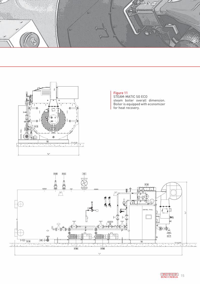
Figure 11STEAM-MATIC SG ECOsteam boiler overall dimension. Boiler is equipped with economizer for heat recovery.

16
TECHNICAL SPECIFICATIONS
Features UnitSG PA
600
SG PA
800
SG PA
1000
SG PA
1200
SG PA
1500
SG PA
2000
SG PA
2200
SG PA
2500Nominal steam
production Kg/h 6000 8000 10000 12000 15000 20000 22000 25000
Design pressure* bar 12 15 18 12 15 18 12 15 18 12 15 18 12 15 18 12 15 18 12 15 12 15
Min.feed water temp. °C 90 90 90 90 90 90 90 90Thermal efficiency (with
air preheater)** % 92,5 92 91,5 92,5 92 91,5 92,5 92 91,5 92,5 92 91,5 92,5 92 91,5 92,5 92 91,5 92,5 92 92,5 92
OVERALL DIMENSIONS AND CONNECTIONS
L Lenght mm 7150 7650 7900 8400 9200 10.000 *** ***
W Width mm 3000 3000 3250 3250 3600 3.600 *** ***
H
Height (with
air prehe-
ater)mm 3700 3700 4050 4050 4560 4.560 *** ***
N2 Steam valveDN 125 125 100 150 125 100 150 150 125 150 150 150 200 150 150 200 200 200 250 200 250 200
PN 16 40 40 16 40 40 16 40 40 16 40 40 16 40 40 16 40 40 16 40 16 40
N4A
N4B
Safety valve
outlet
DN40/
65
40/
65
40/
65
40/
65
40/
65
40/
65
50/
80
40/
65
40/
65
50/
80
50/
80
40/
65
65/
100
50/
80
50/
80
65/
100
65/
100
50/
80
65/
100
80/
100
65/
100
65/
100
PN25/
16
25/
16
40/
16
25/
16
25/
16
40/
16
25/
16
25/
16
40/
16
25/
16
25/
16
40/
16
25/
16
25/
16
40/
16
25/
16
25/
16
40/
16
25/
16
25/
16
25/
16
25/
16
N9 Boiler drainDN 40 40 40 40 40 40 40 40
PN 16 16 16 16 16 16 16 16
N
18A
18B
Feed water
line*****Ø 3” 3” 4” 4” 4” 5” 5” 6”
N16
Reversal
chamber
drain
DN 32 32 32 32 32 32 32 32
PN 16 16 16 16 16 16 16 16
N15Heavy fuel
oil inletØ 2” 2” 2”½ 2”½ 2”½ 2”½ 2”½ 2”½
N17Natural gas
inletØ 3” 4” 4” 4” 5” 5” 5” 6”
N19Stack
connectionmm 600 600 720 720 800 850 920 920
Empty weight T 18,0 18,8 19,7 21,0 22,0 23,2 24,0 25,3 27,1 27,0 28,6 30,2 35,0 37,2 39,1 40,0 43,4 45,0 41,9 44,4 43 45,5
Water volume at
levelm3 9,3 10,0 11,0 13,0 17,7 19,0 22,0 36,0
Full water volume m3 12,3 13,3 15,0 18,0 23,5 26,0 29,3 42,0
TOTAL ELECTRIC POWER
Heavy fuel oil **** KW 35,3 36,8 38,8 38,8 38,8 42,8 48,8 52,8 52,8 56,8 60,8 64,3 71,1 74,6 78,1 82,6 86,1 101,1 89,0 92,0 101,0
Natural gas or
diesel oilKW 23,0 24,0 26,0 26,0 26,0 30,0 33,0 37,0 37,0 41,0 45,0 48,5 52,0 55,5 59,0 64,0 67,0 67,0 75,0 78,0 86,0
Standard electric power data: 400 V/50 Hz/ – 3 phases Auxiliaries voltage: 220 V
FUEL CONSUMPTION
Heavy fuel calorific power: 9700 kcal/kg (for actual fuel consumption calculation see Appendix 1).
Diesel fuel calorific power: 10200 kcal/kg (for actual fuel consumption calculation see Appendix 1).
Natural gas calorific power: 8500 kcal/Nm3 (for actual fuel consumption calculation see Appendix 1).
* Design pressure above 18 bar or below 12 bar on request.
** Thermal efficiency at 100% of the load, with water temperature 90 °C.
*** Height is calculated without air fan.
**** Connection size depends on feed water pump supplier.
***** Maximum heavy fuel viscosity is 7°E under 50°C temperature. Information about heavy fuel with higher viscosity on request.
Table 3
Technical specifications and overall dimensions of steam boiler STEAM-MATIC SG PA with air preheater. The below listed information is generalized to
the entire range of models STEAM-MATIC SG PA, it’s only indicative and may change in accordance with each final boiler configuration. Additional data
and deviations from standard are available on request.
3. TECHNICAL SPECIFICATIONS - STEAM-MATIC SG PA (WITH AIR PREHEATER)

17
Figure 12STEAM-MATIC SG PAsteam boiler overall dimension. Boiler is equipped with air preheater for heat recovery.

18
3. TECHNICAL SPECIFICATIONS - THERMAL EFFICIENCY
Figure 14 The coefficient of performance (COP) of the steam boiler STEAM-MATIC equipped with economizer*.
* Load, % = * 100% , with T feed water at 90° C.
Figure 13 The coefficient of performance (COP) of the steam boiler STEAM-MATIC crossed with the load*.

19
The quality of the water constitutes one of the most important factors regarding duration, safety and reliability of the steam generator and therefore the entire thermal plant. The “water circuit” elements are essentially comprised of:• Unpurified water treatment system: treats the waters available, making them suitable for re-integration into the plant. The most common methods of treatment are: filters, softeners, reverse osmosis plants, demineralizers, etc. • Thermophysical degaser: it is made up from an accumulation tank where condensate returning from the utilities and reintegration water converge. Heating takes place inside the degaser by introducing a regulated flow rate of steam. The purpose of the treatment is to eliminate the gaseous fractions dissolved in the feed water, particularly considering oxygen.• Chemical products dosing control unit: it is made up from one or more tanks fitted with manually regulated dosing pumps, which send the chemical products into the water supply circuit. Some chemical products must be stored in a tank fitted with stirrer.• Boiler bottom outlet and surface blowdown: they allow to keep the amount of salts dissolved and the amount of slurry inside the boiler drum within the envisioned limits. The quantity of the continuous blowdown operations is tightly linked to the percentage of total solids in the boiler water: the assistance of a laboratory specialized in the analysis of water can help in defining the real quantity and frequency of blowdown operations necessary to maintain normal concentrations.
Table 4Feedwater Quality Requirements for best STEAM-MATIC SG opera-tion and preservation
(a) With copper alloys in the system the pH value shall be maintained in the range from 8.7 to 9.2.
(b) With softened water pH value >7.0 - see the manual of the boiler.
(c) If the operating pressure is <1 bar, the max total acceptable hardness should be 0.05 mmol / l.
(d) In order to observe this value at intermitted operation or operation without deareator an oxygen scavenger shall be used.
(e) Organic substances are generally a mixture of several different compounds. The composition of such mixtures and behaviour of their
individual components under the conditions of boiler operation are difficul to predict. Organic substances may be decomposed to form
carbonic acid or other acidic decomposition products which increase the acid conductivity and cause corrosion or deposits. They also
may lead to foaming and/or priming which shall be kept as low as possible.
3. TECHNICAL SPECIFICATIONS - WATER PROPERTIES
PARAMETERS UNIT FEED WATER PROPERTIES
ACCORDING TO EN 12953
OPERATING PRESSURE (X) bar (= 0,1 MPa) 0,5 < X < 20 X > 20
APPEARANCE / Clean, free from suspended
solids
DIRECT CONDUCTIVITY AT 25°C μS/cm Not specified
pH VALUE AT 25 °C (a) / > 9,2 (b) > 9,2 (b)
TOTAL HARDNESS (Ca + Mg) mmol/l < 0,01 (c) < 0,01
IRON (Fe) CONCENTRATION mg/l < 0,3 < 0,1
COPPER (Cu) CONCENTRATION mg/l < 0,05 < 0,03
SILICA (SiO2) CONCENTRATION mg/l Not specified
OXYGEN (O2) CONCENTRATION mg/l < 0,05 (d) < 0,02
OIL/GREASE CONCENTRATION
(see EN 12953-6)mg/l < 1 < 1
ORGANIC SUBSTANCES CONCENTRATION / See footnote (e)

20
Figure 15Boiler room general P&ID. The data processing schemes are standardized to the entire STEAM-MATIC SG range; further measurements and modifications are available on-demand.
4. P&ID - STEAM-MATIC SG - BOILER ROOM
SG – P&ID Elements Description
S1 Water Softener
V1 Feed Water / Condensate Tank
V2 Brine Tank
V3 Chemical Dosing Station
SG – P&ID Ancillaries Symbols Meaning
LV Level Valve
LI Level Indicator
FQ Flow Indicator Totaliser
PI Pressure Indicator

21
INSTRUMENTATION SYMBOLS AND
IDENTIFICATION ISA S-5.1

22
SG – P&ID Elements Description
BDS Blowdown system (OPTION)
L1 Chimney (OPTION)
O2 Flue gas oxygen control system (OPTION)
P1 Feed water pump
P2 Second feed water pump (spare) (OPTION)
TDS Automatic TDS control system (OPTION)
Figure 16STEAM-MATIC SG P&ID. Further
measurements and modifications are
available on-demand.
4. P&ID - STEAM-MATIC SG
SG – P&ID Ancillaries Symbols Meaning
AI Alarm Indicator
AE Alarm Element
AIC Analyzer Indicator Controller
AT Analyzer Transmitter
AV Analyzer Valve
FC Flow Controller
LV Level Valve
LI Level Indicator
LAH Level Alarm High
LAHH Level Alarm High Above LAH
LAL Level Alarm Low
LALL Level Alarm Low Below LAL
LIC Level Indicator Controller
LSL Level Switch Low
LSLL Level Switch Low Below LSL
LSL/H Level Switch Low/High
LSH Level Switch High
LSHH Level Switch High Above LSH
LT Level Transmitter
M Motor
PAH Pressure Alarm High
PAHH Pressure Alarm High Above PAH
PI Pressure Indicator
PIC Pressure Indicator Controller
PSH Pressure Switch High
PSHH Pressure Switch High Above PSH
PSV Pressure Safety Valve
PT Pressure Transmitter
TAH Temperature Alarm High
TE Temperature Element
TI Temperature Indicator
TSH Temperature Switch High

23
SUPPLY LIMIT
CANNON BONO CUSTOMER
INSTRUMENTATION SYMBOLS
AND IDENTIFICATION ISA S-5.1
Functions managed by “OPTISPARK” system
Combustion control system
Instrument air
Interlock - burner shutdown
Burner
OPTION

24
4. P&ID - STEAM-MATIC SG ECO - WITH ECONOMIZER
SG – P&ID Elements Description
E1 Economizer
BDS Blowdown system (OPTION)
L1 Chimney (OPTION)
O2 Flue gas oxygen control system (OPTION)
P1 Feed water pump
P2 Second feed water pump (spare) (OPTION)
TDS Automatic TDS control system (OPTION)
Figure 17
STEAM-MATIC SG ECO (with economizer) P&ID;
further measurements and modifications are available
on-demand.
SG – P&ID Ancillaries Symbols Meaning
AI Alarm Indicator
AE Alarm Element
AIC Analyzer Indicator Controller
AT Analyzer Transmitter
AV Analyzer Valve
FC Flow Controller
LV Level Valve
LI Level Indicator
LAH Level Alarm High
LAHH Level Alarm High Above LAH
LAL Level Alarm Low
LALL Level Alarm Low Below LAL
LIC Level Indicator Controller
LSL Level Switch Low
LSLL Level Switch Low Below LSL
LSL/H Level Switch Low/High
LSH Level Switch High
LSHH Level Switch High Above LSH
LT Level Transmitter
M Motor
PAH Pressure Alarm High
PAHH Pressure Alarm High Above PAH
PI Pressure Indicator
PIC Pressure Indicator Controller
PSH Pressure Switch High
PSHH Pressure Switch High Above PSH
PSV Pressure Safety Valve
PT Pressure Transmitter
TAH Temperature Alarm High
TE Temperature Element
TI Temperature Indicator
TSH Temperature Switch High

25
SUPPLY LIMIT
CANNON BONO CUSTOMER
INSTRUMENTATION SYMBOLS
AND IDENTIFICATION ISA S-5.1
OPTION
Functions managed by “OPTISPARK” system
Combustion control system
Instrument air
Interlock - burner shutdown
Burner

26
4. P&ID - STEAM-MATIC SG PA - WITH AIR PREHEATER
SG – P&ID Elements Description
PA Air preheater
BDS Blowdown system (OPTION)
L1 Chimney (OPTION)
O2 Flue gas oxygen control system (OPTION)
P1 Feed water pump
P2 Second feed water pump (spare) (OPTION)
TDS Automatic TDS control system (OPTION)
Figure 18
STEAM-MATIC SG PA (with air preheater) P&ID;
further measurements and modifications are
available on-demand.
SG – P&ID Ancillaries Symbols Meaning
AI Alarm Indicator
AE Alarm Element
AIC Analyzer Indicator Controller
AT Analyzer Transmitter
AV Analyzer Valve
FC Flow Controller
LV Level Valve
LI Level Indicator
LAH Level Alarm High
LAHH Level Alarm High Above LAH
LAL Level Alarm Low
LALL Level Alarm Low Below LAL
LIC Level Indicator Controller
LSL Level Switch Low
LSLL Level Switch Low Below LSL
LSL/H Level Switch Low/High
LSH Level Switch High
LSHH Level Switch High Above LSH
LT Level Transmitter
M Motor
PAH Pressure Alarm High
PAHH Pressure Alarm High Above PAH
PI Pressure Indicator
PIC Pressure Indicator Controller
PSH Pressure Switch High
PSHH Pressure Switch High Above PSH
PSV Pressure Safety Valve
PT Pressure Transmitter
TAH Temperature Alarm High
TE Temperature Element
TI Temperature Indicator
TSH Temperature Switch High

27
SUPPLY LIMIT
CANNON BONO CUSTOMER
INSTRUMENTATION SYMBOLS
AND IDENTIFICATION ISA S-5.1
OPTION
Functions managed by “OPTISPARK” system
Combustion control system
Instrument air
Interlock - burner shutdown
Burner
TDS

28
Figure 19
Natural gas combustion system P&ID. The data
processing schemes are standardized to the entire
STEAM-MATIC SG range; further measurements
and modifications are available on-demand.
4. P&ID - SG - NATURAL GAS BURNER
SG – P&ID Elements Description
U10 Combustion air fan
U11 Silencer
SG – P&ID Ancillaries Symbols Meaning
BALL Flame alarm low level
BE Flame scanner
BSLL Flame switch low level
BV On/off actuated valve
BZ Electrical igniter
FC Frequency controller
FV Flow valve
M Motor
PAHH Pressure alarm high high
PALL Pressure alarm low low
PCV Pressure control valve
PI Pressure indicator
PSLL Pressure switch low low
VSP Gas leakage test
SUPPLY LIMIT
CANNON BONO CUSTOMER
INSTRUMENTATION SYMBOLS
AND IDENTIFICATION ISA S-5.1
OPTION
Functions managed by “OPTISPARK” system
Combustion control system
Burner management system
Instrument air
Interlock - burner shutdown
Burner
Joint

29

30
Figure 20
Liquid fuel oil combustion system P&ID. The data processing schemes are standardized to the entire
STEAM-MATIC SG range; further measurements and modifications are available on-demand.
4. P&ID - SG - LIQUID FUEL OIL BURNER (HEAVY FUEL OIL AND DIESEL OIL)
SG – P&ID Elements Description
U10 Combustion air fan
U11 Silencer
P10A Fuel oil pump
P10B Fuel oil pump (spare) (OPTIONAL)
E10 Fuel oil preheater
SG – P&ID Ancillaries Symbols Meaning
BALL Flame alarm low levef PALL Pressure alarm low low
BE Flame scanner PCV Pressure control valve
BSLL Flame switch low level PI Pressure indicator
BV On/off actuated valve PSLL Pressure switch low low
BZ Electrical igniter TAL Temperature alarm low
FC Frequency controller TSL Temperature switch low
FV Flow valve TIC Temperature indicator controller
HV Hand valve TE Thermoelement
M Motor
Functions managed by
“OPTISPARK” system
Combustion control system
(managed by “OPTISPARK”)
Burner management system
Interlock - burner shut down
Burner
Autocleaner strainer
Filter “Y” type
Condensate drain
Sight glass
Instrument air (MIN 5 bar - MAX 7)
SUPPLY LIMIT
CANNON BONO CUSTOMER
INSTRUMENTATION SYMBOLS
AND IDENTIFICATION ISA S-5.1
OPTION

31
32
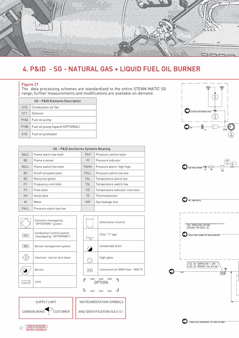
Figure 21The data processing schemes are standardized to the entire STEAM-MATIC SG range; further measurements and modifications are available on-demand.
4. P&ID - SG - NATURAL GAS + LIQUID FUEL OIL BURNER
SG – P&ID Elements Description
U10 Combustion air fan
U11 Silencer
P10A Fuel oil pump
P10B Fuel oil pump (spare) (OPTIONAL)
E10 Fuel oil preheater
Functions managed by
“OPTISPARK” system
Combustion control system
(managed by “OPTISPARK”)
Burner management system
Interlock - burner shut down
Burner
Joint
Autocleaner strainer
Filter “Y” type
Condensate drain
Sight glass
Instrument air (MIN 5 bar - MAX 7)
SUPPLY LIMIT
CANNON BONO CUSTOMER
INSTRUMENTATION SYMBOLS
AND IDENTIFICATION ISA S-5.1
OPTION
SG – P&ID Ancillaries Symbols Meaning
BALL Flame alarm low levef PCV Pressure control valve
BE Flame scanner PI Pressure indicator
BSLL Flame switch low level PAHH Pressure alarm high high
BV On/off actuated valve PSLL Pressure switch low low
BZ Electrical igniter TAL Temperature alarm low
FC Frequency controller TSL Temperature switch low
FV Flow valve TIC Temperature indicator controller
HV Hand valve TE Thermoelement
M Motor VSP Gas leakage test
PALL Pressure alarm low low

33

34
5. BOILER LAYOUT - BOILER ROOM
Figure 22 A sample installation of a SG STEAM-MATIC inside a boiler room, plan view
4
1
2
8002500
1500
1500
min.800450
600
1500
350
* *
**
1500
5600
5
prof
. Z 2
0x3
Round bar 10
Flat bar 80X8
Chequered plateelev. 0.0
every ~2 mt.
500
650

35
1 Steam Boiler SG
2 Water-condensate storage tank
3 Structure supporting tank
4 Feed water treatment unit
5 Steam header
6 Chimney
Figure 23 A sample installation of a SG STEAM-MATIC inside a boiler room, front view
3
100
2500
min
.min
.150
0
100
710
500
min
.200
0*
1
2
4
6

36
6. INSTALLATION
“Steam-Matic” generator is shipped ready to operate after a fire test in our factory. For installation local State regulation must be observed. Examine the boiler on arrival to control if it has suffered any damage during transport. Any damage should be notified to the carrier. The “Steam-Matic” boiler should be placed on a well leveled concrete floor.
Minimum clearance must be allowed:- rear side min : 1,5 m. for inspection- front side min : sufficient distance for tube cleaning and burner extraction- left side min : 1,5 m. to allow auxiliaries control- right side min : 0,8 m. for inspectionThe boiler room will be kept clean and well ventilated (indicatively 1 m3 per 1 MW of thermal capacity); a mini-mum of two opening is required to provide sufficient air for the burner and avoid excessive room temperature.
Flooring
The generator must rest on a strong and levelled floor, the floor slab must be dimensioned to support spe-cific loads up to 25 N/cm2 and to support the total weight of the generator and its accessories in the full load condition.
The following connections are required.
Boiler piping
- Steam line to the boiler valve- Safety valves piped to atmosphere with the same diameter as the safety valves outlet and with adeguate supports to prevent stress on valves.- Bottom and surface blowdown connection piped a drain flash tank- Water column and sight glass drain piped for blowdown
Flue gas outlet
The generator is supplied with carbon steel counterflange on the fumes exhaust connection, which the in-staller can use to weld the fumes pipe or the vertical flue.
The fumes connection is dimensioned to support the weight of the flue overlaying for a maximum height of 10 metres from the floor surface (considering the flue pipe realised in steel with thickness of 6 mm). Horizontal loads and moments must be avoided. For applications that do not lie within the previously described cases, consult the Bono Energia Technical Dept.
Steam connection
It shall connect the steam main valve to the steam header.The piping must allows the thermal expansions in order to avoid stress on the valve.If the utilities pressure is less than the generator operating pressure or if a constant pressure is required it is necessary to install a reducing valve provided with by-pass.

37
Water and condensate piping
The water tank receives the condensate and treated water. The float valve controls the treated water inlet; up-stream the float valve it is advisable to install an gate valve to allow removal of float valve for maintenance pur-poses. In the tank upper section there are the vent and the condensate flanges. The over flow and blowdown connections are placed on the tank too. A filter is installed on the feed water pump suction side to pro¬tect the pump. The pipe must be as straight as possible. The height of the feed tank must assure the necessary head to a¬void pump cavitation and consequent insufficient water feed.
Oil piping (if any)
The main tank must be installed according to the Local Authority Specification.It is necessary to heat the oil on the tank outlet to facilitate the pumping during cold seasons.
The pre-heating temperature is about 40-60°C.Electrical tracing of heavy fuel oil lines is required to keep the oil at constant temperature while pumped.
Safety valves
Safety valve discharge has to be vented to atmosphere with a tube of same diameter than valve outlet at least following the most direct way.
The discharge pipe must be provided, at its lowest point with a condensate drain pipe and must be adequately supported and free to expand without stress on the valves.
ELECTRIC POWER CONNECTION
Connect electric line to RST terminals in boiler panel according to wiring diagram.Check that line voltage is within + 5% of nominal value.The general 3 phase switch, shall be provided and installed preferably outside the boiler room.
HYDRAULIC TEST
If hydraulic test is required, proceed as follows in order to prepare the generator for the hydraulic test:
- Exclude the safety valves by placing a steel disk with suitable thickness between the flanges and close the boiler valves.- Close the pressure-switch on-off cock to prevent any damage to the internal parts.- Remove the outlet cap from the level indicator and make the connection to the hand pump.- Fill the generator with purified water using the boiler feed pump. Remember, in the event of a centrifugal pump, narrow the pump delivery in order to limit motor absorption. As for a single-impeller feed pump, the delivery valve must be open. - During the filling phase vent the air through the vent valve until water flows out; then close the vent valve.- When filling has been completed, make sure that the 3-way cock connected to the boiler manometer is open, pressurise the boiler with the centrifugal pump and then with the hand pump until the prescribed hydraulic test pressure is reached.

38
BOILER START UP
Boiler Filling
When filling the boiler, the water must appear just above the normal level (block) in a way to allow successive expansion when the water itself is heated.
At least one vent valve must be left open during the filling phase to prevent pressurisation of the boiler due to the effect of the air it contains; the operator must monitor the pressure trend carefully and stop the pump if any anomalies are detected.
Boiler must be filled slowly, in particular if water is hot, so that no dangerous stress occurs in pressure parts.
If boiler is partially filled, temperature of new water that is introduced shall be not higher or lower than 25 °C than temperature of water already present in the boiler.
Usually water temperatury should not less than 20°C for filling operation; if temperature is higher than 40°C filling must be carried out with extreme precautions.
IMPORTANT: drain levels and look at the filling to verify cleanliness and operation. For filling use only wa-ter with suitable characteristics
Preliminary operations
Before starting the boiler check that all auxiliary devices have been tested.
The following procedure is a summarised list of main controls to be carried out before starting up:
• check water level on level gauges: the level must be 30 mm over the block value• check level gauges opening drains and looking at refilling• check regulation valves drains and vents• check safety valves installation and verify congruence between set point and stamp pressure of valves• check minimum position of combustion air damper• check all flanged connections and gaskets presence and check all bolts• check that the man hole and the inspection hatches are closed with the bolts tightened and the gaskets
in position;• check that the requested quality of hot water is available• check all safety logics and interblocks and check all safety instruments
ATTENTION: if any of above checks has negative result do not start up boiler.
6. INSTALLATION

39
STARTING UP
After carrying out above operations boiler can be started up.
Burner operation and combustion shall be controlled during start up; air / fuel ratio shall be set in respect of flue gas analysis at different loads. CO content shall be limited within local law requirements.
Burner shall be ignited following relevant instructions and with strict respect of safety instructions consider-ing also of fuel type
Boiler must be at minimum until steam flows from vent valve; from this situation is possible to closo vent valve and increase pressure.
Pressure shall be increased with burner low load.
ATTENTION: too rapid temperature increase can create dangerous sress conditions and cause cracks
STEAM PRODUCTION
When set pressure is reached with boiler at minimum load, load can be increased and control can be set for automatic operation.
ATTENTION: the system shall be kept continuously controlled until MCR has been reached to verify that no defects in safety system is present.
NORMAL OPERATION
When boiler begins maximum load production it is necessary to verify normal conditions for continuos eco-nomical and safe operation. Temperatures, pressure capacities shall be measured with precision and conti-nuity and shall be compared with design figures; in particular flue gas temperature is directly associated with efficiency: an increase of this temperature is a decrease of efficiency.
An increase of pressure in combustion air / flue gas system indicate that flue gas channels are dirty and clean-ing operation is urgently needed.
It is advisable to record all measures on a log book and in particular:
• fuel consumption• flue gas analysis• flue gas temperature• air / flue gas pressure• operation time and load• any other useful note necessary to create a databank of the boiler.

40
During boiler operation a particular attention shall be paid to
A) Boiler water level
The normal water level in the boiler must be maintained at all times. If this is too high, water may be dragged into the steam, thus compromising its purity. If the level is too low, the boiler pipes may overheat or, in ex-treme cases, break. When in very low conditions, switch the fires off immediately and look for the causes of this situation before igniting again.
ATTENTION: If level is below minimum stop immediately the burner and in any case do not refill with cold water the boiler. The furnace may explode immediately.
Levels gauges and switches shall be always perfectly efficient; level gauges shall be drained at any periodical personnel rotation to verify cleanliness.
Level gauges purge shall be carried out full opening slowly drain cocks and closing them looking at refilling: if water is drained too slowly repeat operation to purge levels from dirty.
B) Water treatment and continuous blow down (see also Table 4)
The chemical treatment of the feed water, the conditioning of the boiler water and the regulation of the con-centration of the salts in the boiler water must be set accurately, as soon as the new boiler is used.
Blow down capacity shall be directly connected to total salt concentration in boiler water: periodical chemical analysis of boiler water are necessary to define exact capacity of blow down
C) Combustion
Efficient combustion is fundamental for good boiler operation: bad combustion can cause the production of unburned fuels, thus compromising boiler performance along with the formation of carbon deposits on the inner surfaces of the pipes with consequent dirtying (and further penalisation of performance).
Therefore combustion shall be monitored continuously.
In general good combustion is obtained with perfect air distribution in the burner: the position of the air swirler shall be correct and checked periodically.
ATTENTION: it is absolutely necessary to respect all instructions of burner manufacturer during start up, normal operation and shut down of the burner. In particular it is always necessary to purge combustion chamber (with combustion air) before any burner start-up.
Combustion shall be optimised verifying air /fuel ratio (air excess) at any boiler and burner load. Air excess measurement can be performed by means of a flue gas oxygen content analysis; too high air excess causes efficiency reduction. It is therefore necessary to periodically analyse the fumes released into the flue, in order to verify the correct
maintenance of the operating parameters.
6. INSTALLATION

41
BOILER SHUTDOWN
When the boiler is stopped, the burner and the air fan must be put out of service following the Standards inher-ent the combustion system used.
Particular attention must be paid to the conditions in which the combustion system is left. When the burner has been switched off, the air fan must be left in service in order to complete cleaning of the combustion chamber and eliminate any trace of unburned fuel residues and then stopped.
The boiler must be left to cool down slowly as uniformly as possible. Accelerating cooling of the combustion chamber by allowing large masses of cold air to pass through the plant could lead to damage of the refractory materials and useless tensions in the pressurised parts.
Later, when the refractory materials have reached lower temperatures, the use of a small air flow through the burner will be allowed. At this point, the pressure in the boiler must be left to decrease naturally, without with-drawing steam or opening the valves. When the pressure has dropped below 1 bar, a vent valve can be opened.
When it is necessary to empty the boiler, boiler water temperature shall be below 100°C before openig boilers drains.
ATTENTION: before opening drains check if vent valve is opened to avoid vacuum condition in the boiler.
When the boiler has been fully drained inernal inspection can be performed.

42
7. SCOPE OF SUPPLY - STANDARD EQUIPMENT
STANDARD EQUIPMENT - STEAM-MATIC SG
BOILER
PRESSURE VESSEL
Cylindrical furnace fitted with expansion joints up to model SG 1200 (corrugated type from model SG
1500)
Shell equipped with manholes, inspection and cleaning doors, flanged doors, steam outlet branch
Moisture separator
Front and rear tube plates dished type, butt-welded to the shell and the furnace
Smoke tubes expanded and welded to the tube plates, internal turbulator system
Flanged connection for self-supporting stack, with counterflange
Water tube reversing chamber with upper and lower headers welded to the rear tube plate
INSULATION AND
EXTERNAL
LAGGING
Insulation of the external casing in mineral wool panels, stainless steel external lagging
BASE Base frame made with iron bars
VALVES AND
ACCESSORIES
Main steam valve (manual)
N.2 Pressure safety valves
Shell blow down valve (surface)
N.2 Level indicators, with shut-off valve
N.2 Shell drain valves
N.2 Reversal chamber blow down valves
Flue gases thermoelement at the stack base
Flue gases sampling point at the stack base
Rear flame sight hole
WATER FEEDING
GROUP
Multi stage centrifugal pump (horizontal design)
On-off valve
Level regulation system with 1 pc. modulating pneumatic valve
Check valve

43
STANDARD EQUIPMENT - STEAM-MATIC SG
BURNING SYSTEM
(modulating
regulation)
Burner box
Flame scanner
Observation port for flame control
Air swirler
Combustion air fan
Burning ignition torch
NATURAL GAS
FUEL (NG)
Natural gas pressure gauge
Internal gas header with multi-nozzle system
N.2 Feeding gas train electrically actuated shut-off valves
Feeding gas electrically actuated regulating valve
N.2 Burning ignition safety solenoid valves
HEAVY FUEL OIL
(HFO)
Fuel pump station, complete with on/off valve
Preheating station steam-electrical thermoregulation system
DIESEL OIL (DO) Fuel pump station, complete with on/off gate valve
SAFETY AND
CONTROL
EQUIPMENT
FOR THE
BOILER
Burner management system for burner ignition and flame control BMS (safety automatic device)
Safety pressure switch for minimum air combustion pressure
Temperature regulation system (only heavy fuel oil)
Gas leakage test- VPS (only gas fuel)
N.2 Max/min fuel pressure switches
Steam pressure transmitter
Shut-down pressure switch for max steam pressure
Automatic pressure modulating control regulator
Automatic modulating level control regulator
ELECTRIC
WIRING
With flexible conduits and tight terminal fittings for high mechanical resistance and water proof
sealing
ELECTRIC PANEL
Steel cabinet, oven painting, front door, IP54 protection
Power section, main switch and door locking device, magneto-thermal switches to protect each
power user, tropicalized power contactors
Control auxiliary section, ignition and flame control panel, alarms and shut-down logic, alarm
horn contacts, auxiliaries protection fuses
Operators panel, burner START/STOP switch/indicator, feed pump START/STOP switch/indica-
tor, alarms acknowledgement with lamps
TY
PE
OF
FU
EL
AV
AIL
AB
LE
*
* dual fuel burning systems are available (NG + HFO, NG + DO) and include the burning system equipment above listed for each fuel type.

44
7. SCOPE OF SUPPLY - OPTIONAL EQUIPMENT
OPTIONAL EQUIPMENT* - STEAM-MATIC SG
ECONOMISER
(FOR HIGH
EFFICIENCY
UP TO 95%)
Package unit bult-in the front side of the generator structure insulation
Carbon steel tube bundle made of finned tubes and elbows
Set of headers for water inlet and outlet
N.2 Inspection and maintenance upper doors
SET OF
INSTRUMENTS
FOR
ECONOMISER
Vent valves
Drain valve
N.2 Temperature gauge for inlet and outlet temperature
N.2 Shut-off manual valves
N.2 Pressure points
Safety valve
By pass valve (manual)
AIR
PREHEATER
(FOR HIGH
EFFICIENCY
UP TO 92%)
Package unit bult-in the front side of the generator structure
Double vertical carbon steel tubes bank, with flue gases running inside and air running outside the tubes.
N.2 Inspection and maintenance upper doors
SECOND FEED
WATER PUMP AS
SPARE (Installed
on boiler base
frame and
connected to the
boiler skid)
Multi stage centrifugal pump (horizontal design)
On-off valve
Check valve
FEEDING PUMP
SPEED CONTROL
SYSTEM (available
for each pump)
Feeding pump speed control system (drived by electrical inverter)
Feed water pressure control loop
COMBUSTION AIR
FAN SPEED
CONTROL SYSTEM
Electrical inverter
SPARE FUEL PUMP Spare fuel pump (available for liquid fuel burner)
AUTOMATIC
BOILER CONTROL
SYSTEM
«OPTISPARK»
BONO Optispark industrial boilers management and control automatic system
Flue gas oxygen control system with separated probe
Control system of the air/fuel ratio (SRC) and of the supply of oxygen (electric cam)

45
OPTIONAL EQUIPMENT* - STEAM-MATIC SG
«SAFESPARK»
SYSTEM (24 HOUR)
System for 24 hour boiler operating without human presence according to
EN 12953 Directive
N.2 Automatically controlled minimum level probes with periodical test, complete with switch
Automatically controlled high level probes with periodical test, complete with switch
Upgraded photocell, with automatically controlled periodical test
“SAFESPARK”
SYSTEM (72 HOUR)
System for 72 hour boiler operating without human presence according to
EN 12953 Directive
N.2 Automatically controlled minimum level probes with periodical test, complete with switch
Automatically controlled high level probes with periodical test, complete with switch
Upgraded photocell, with automatically controlled periodical test
Automatic TDS control system
Automatic blowdown
TDS CONTROL
SYSTEMAutomatic TDS control system (already included in “SAFESPARK” system 72 hour)
AUTOMATIC
BLOW-DOWN SYSTEMAutomatic blowdown system (already included in “SAFESPARK” system 72 hour)
LADDER AND
PLATFORMLadder and platform
THERMO - PHYSI-
CAL DEAERATOR
(ATMOSPHERIC OR
LOW-PRESSUR-
IZED)
Cylindrical body in carbon steel
Set of flanged connections
Support frame in carbon steel
Water on-off automatic valve
Feed water distribution system
Level indicator
Drain connection
Drain valve
Degassing tower (for low-pressurized deaerator)
WATER SOFTENER Water softening station DUPLEX type (other types on request)
CHEMICAL DOSING
STATIONChemical dosing station (pH conditioner, oxygen scavenger)
BLOWDOWN
VESSELBlowdown vessel
STEAM
SUPERHEATER
Shell and tube configuration that heats the saturated steam coming from the cylindrical drum, exchan-
ging heat with the fumes, complete with safety valve and thermostat.
STEAM
HEADERSteam header collecting system
CHIMNEYChimney complete with duct to connect boiler’s flue gas outlet, basaplate structure, cylindrical structure
shell and anchor points to fix wool panels for insulation
* complete list of all available components on request

46
8. APPENDIX 1. FUEL CONSUMPTION CALCULATION
We assume that we have to calculate natural gas fuel consumption for the production of 5500 kg/h of saturated steam,
working pressure is 13 bar, the fire tube steam boiler is a STEAM-MATIC SG 600 with economizer. Feed water temperature
is 90 °C.
As nominal steam production of the fire tube steam boiler STEAM-MATIC SG 600 is 6000 kg/h, while actual steam produc-
tion is 5500 kg/h, we calculate the load with the following equation (feed water T = 90 °C)-
According the graphic regarding the coefficient of performance (COP) of the steam boiler STEAM-MATIC SG ECO, equipped with economizer crossed with load (see Figure 14), we define that COP is 94,7%.
In accordance with heat balance equation Q = M steam * (hg-he)/3600, where:
Q – heat needed to achieve saturated steam production with the above indicated characteristics (watt);
M steam - steam production (t/h);
hg – enthalpy of saturated steam at the above indicated steam pressure and water temperature (kcal/kg);
he – enthalpy of feeding water at the above indicated water temperature (kcal/kg);
According to the table of thermodynamic characteristics of water and saturated steam (Appendix 2), we define value hg under 13 bar pressure gauge and he with 90 °C.
Actual useful thermal load is defined by the relation:
Q actual useful = 5 500 * (666,8 – 90,0) = 3 172 400 kcal/h.
Total thermal power in the burner is defined by the equation:
Q burner = Q actual useful / (COP,%/100),
Q burner = 3 172 400/(94,7/100) = 3 349 947 kcal/h.
Fuel heat capacity of natural gas is 8500 kcal/Nm3.
We define fuel consumption per hour of natural gas under normal conditions from the relation:
3 349 947/8 500 = 394 Nm3/h.
Load, % = * 100% Load, % = * 100% = 92% 6000
5500
91
92
93
94
95
96
25 50 75 100
Effic
ienc
y %
% LoadEfficiency at 10 bar Efficiency at 13 bar Efficiency at 16 bar

47
9. APPENDIX 2. THERMODYNAMIC CHARACTERISTICS OF SATURATED STEAM
Pm Pa T V he r hg
bar kg/cm2 bar kg/cm2 K °C m3/kg kJ/kg kcal/kg kJ/kg kcal/kg kJ/kg kcal/kg
0,050 0,051 306,05 32,9 28,191 137,7 32,9 2425 679,2 2562,7 612,1
0,100 0,102 318,95 45,8 14,674 191,8 45,8 2394,4 571,9 2586,2 617,7
0,150 0,153 327,15 54,0 10,023 225,9 54,0 2374,8 567,2 2600,7 621,2
0,200 0,204 333,15 60,0 7,65 251,5 60,1 2359,7 563,6 2611,2 623,7
0,250 0,255 338,15 65,0 6,204 272,0 65,0 2347,5 560,7 2619,5 625,7
0,300 0,306 342,25 69,1 5,229 289,3 69,1 2337,5 558,3 2626,8 627,4
0,350 0,357 345,85 72,7 4,526 304,3 72,7 2328,7 556,2 2633 628,9
0,400 0,408 349,05 75,9 3,994 317,6 75,9 2320,7 554,3 2638,3 630,2
0,450 0,459 351,85 78,7 3,577 329,6 78,8 2313,6 552,6 2643,2 631,4
0,500 0,510 354,45 81,3 3,240 340,5 81,4 2306,9 551,0 2647,4 632,4
0,6 0,612 359,05 85,9 2,732 359,9 86,0 2295,2 548,2 2655,1 634,2
0,7 0,714 363,05 89,9 2,365 376,7 90,0 2284,3 545,6 2661,0 635,6
0,8 0,816 366,65 93,5 2,087 391,7 93,6 2275,5 543,5 2667,2 637,1
0,9 0,918 369,85 96,7 1,869 405,2 96,8 2267,2 541,5 2672,4 638,3
1,0 1,020 372,75 99,6 1,694 417,5 99,8 2259,2 539,6 2676,7 639,4
0 0 1,013 1,033 373,15 100,0 1,673 419,1 100,1 2258,4 539,4 2677,5 639,5
0,05 0,051 1,063 1,084 374,55 101,4 1,601 425,0 101,5 2254,2 538,4 2679,1 639,9
0,10 0,102 1,113 1,135 375,75 102,6 1,533 430,4 102,8 2251,2 537,7 2681,6 640,5
0,15 0,153 1,163 1,186 378,25 105,1 1,471 435,8 104,1 2247,9 536,9 2683,7 641,0
0,20 0,204 1,213 1,237 379,35 106,2 1,414 440,9 105,3 2245,0 536,2 2685,8 641,5
0,30 0,306 1,313 1,339 380,55 107,4 1,312 450,5 107,6 2238,7 534,7 2689,2 642,3
0,40 0,408 1,413 1,441 382,65 109,5 1,225 459,7 109,8 2232,8 533,3 2692,5 643,1
0,50 0,510 1,513 1,543 384,75 111,6 1,149 468,5 111,9 2227,0 531,9 2695,5 643,8
0,60 0,612 1,613 1,645 386,65 113,5 1,038 476,5 113,8 2221,5 530,6 2698,0 644,4
0,70 0,714 1,713 1,747 388,55 115,4 1,024 484,4 115,7 2216,9 529,5 2701,3 645,2
0,80 0,816 1,813 1,849 390,25 117,1 0,971 491,9 117,5 2211,9 528,3 2703,8 645,8
0,90 0,918 1,913 1,951 391,95 118,8 0,923 499,1 119,2 2206,9 527,1 2705,9 646,3
1,00 1,020 2,013 2,053 393,55 120,4 0,881 505,8 120,8 2202,3 526,0 2708,0 646,8
Pm - gauge pressure Pa - absolute pressure T – temperature V - specific volume
he - specific enthalpy of water r - specific enthalpy of evaporation
of steam
hg - specific enthalpy of saturated steam
Denomination

48
Pm Pa T V he r hg
bar kg/cm2 bar kg/cm2 K °C m3/kg kJ/kg kcal/kg kJ/kg kcal/kg kJ/kg kcal/kg
1,00 1,020 2,013 2,053 393,55 120,4 0,881 505,8 120,8 2202,3 526,0 2708,0 646,8
1,10 1,122 2,113 2,155 395,05 121,9 0,841 512,5 122,4 2198,5 525,1 2711,0 647,5
1,20 1,224 2,213 2,257 396,55 123,4 0,806 519,2 124,0 2194,3 524,1 2713,5 648,1
1,30 1,326 2,313 2,359 398,05 124,9 0,773 525,0 125,4 2190,1 523,1 2715,1 648,5
1,40 1,428 2,413 2,461 399,45 126,3 0,743 530,9 126,8 2186,3 522,2 2717,2 649,0
1,50 1,530 2,513 2,563 400,75 127,6 0,714 536,3 128,1 2181,7 521,1 2718,1 649,2
1,60 1,632 2,613 2,664 402,05 128,9 0,689 542,2 129,5 2178,8 520,4 2721 649,9
1,70 1,733 2,713 2,766 403,25 130,1 0,665 547,2 130,7 2175 519,5 2722,3 650,2
1,80 1,835 2,813 2,868 404,55 131,4 0,643 552,7 132,0 2171,3 518,6 2723,9 650,6
1,90 1,937 2,913 2,970 405,65 132,5 0,622 557,7 133,2 2167,9 517,8 2725,6 651,0
2,00 2,039 3,013 3,072 406,85 133,7 0,603 562,7 134,4 2164,6 517 2727,3 851,4
2,20 2,243 3,213 3,278 409,05 135,9 0,568 571,9 136,6 2158,3 515,5 2730,2 652,1
2,40 2,447 3,413 3,480 411,15 138,0 0,536 581,1 138,8 2152 514,0 2733,1 652,8
2,60 2,651 3,613 3,684 413,15 140,0 0,509 589,5 140,8 2146,2 512,6 2735,7 653,4
2,80 2,855 3,813 3,888 415,05 141,9 0,483 597,9 142,8 2140,3 511,2 2738,2 654,0
3,00 3,059 4,013 4,092 416,85 143,7 0,461 605,8 144,7 2134,8 509,9 2740,7 654,6
3,20 3,263 4,213 4,296 418,55 145,4 0,44 612,9 146,4 2129,4 508,6 2742,4 655,0
3,40 3,467 4,413 4,500 420,35 147,2 0,422 620,5 148,2 2124,4 507,4 2744,9 655,6
3,60 3,671 4,613 4,704 421,95 148,8 0,405 627,6 149,9 2118,9 506,1 2746,5 656,0
3,80 3,875 4,813 4,908 423,55 150,4 0,389 634,3 151,5 2114,3 505,0 2748,6 656,5
4,00 4,079 5,013 5,112 425,15 152,0 0,374 641,0 153,1 2109,3 503,8 2750,3 656,9
4,20 4,283 5,213 5,316 426,55 153,4 0,361 647,3 154,6 2104,7 502,7 2752,0 657,3
4,40 4,487 5 413 5,520 427,95 154,8 0,348 653,6 156,1 2100,1 501,6 2753,7 657,7
4,60 4,691 5,613 5,724 429,35 156,2 0,336 659,8 157,6 2095,9 500,6 2755,8 658,2
5,00 5,099 6,013 6,131 432,05 158,9 0,315 671,1 160,3 2087,1 498,5 2758,3 658,8
5,50 5,608 6,513 6,641 435,25 162,1 0,292 685,0 163,6 2077,1 496,1 2762,0 659,7
6,00 6,118 7,013 7,151 438,15 165,0 0,272 697,9 166,7 2067,4 493,8 2765,4 660,5
6,50 6,628 7,513 7,661 440,95 167,8 0,255 710,1 169,6 2058,2 491,6 2768,3 661,2
7,00 7,138 8,013 8,171 443,65 170,5 0,240 721,8 172,4 2049,0 489,4 2770,8 661,8
7,50 7,648 8,513 8,681 446,15 173,0 0,227 733,1 175,1 2040,6 487,4 2773,8 662,5
8,00 8,158 9,013 9,191 448,55 175,4 0,215 743,6 177,6 2032,3 485,4 2775,8 663,0
9. APPENDIX 2. THERMODYNAMIC CHARACTERISTICS OF SATURATED STEAM

49
Pm Pa T V he r hg
bar kg/cm2 bar kg/cm2 K °C m3/kg kJ/kg kcal/kg kJ/kg kcal/kg kJ/kg kcal/kg
8,50 8,667 9,513 9,700 450,85 177,7 0,204 753,6 180,0 2024,3 483,5 2777,9 663,5
9,00 9,177 10,013 10,210 453,15 180,0 0,194 763,3 182,3 2016,4 481,6 2779,6 663,9
9,50 9,687 10,513 10,720 455,25 182,1 0,185 772,9 184,6 2008,8 479,8 2781,7 664,4
10,00 10,197 11,013 11,230 457,25 184,1 0,177 782,1 186,8 2001,3 478,0 2783,4 664,8
11,00 11,217 12,013 12,250 481,15 188,0 0,163 799,3 190,9 1987,1 474,6 2786,3 665,5
12,00 12,236 13,013 13,269 464,85 191,7 0,151 815,6 194,8 1973,7 471,4 2789,2 666,2
13,00 13,256 14.013 14,289 468,25 195,1 0,141 831,1 198,5 1960,7 468,3 2791,8 666,8
14,00 14,276 15,013 15,309 471,45 198,3 0,132 845,7 202,0 1948,1 465,3 2793,9 667,3
15,00 15,296 16,013 16,328 474,55 201,4 0,124 859,6 205,3 1936,4 462,5 2795,9 667,8
16,00 16,315 17,013 17,348 477,55 204,4 0,117 872,9 208,5 1924,7 459,7 2797,6 668,2
17.00 17,335 18,013 18,368 480,35 207,2 0,110 885,5 211,5 1913,4 457,0 2798,9 668,5
18,00 18,355 19,013 19,388 483,05 209,9 0,105 897,6 214,4 1902,5 454,4 2800,1 668,8
19,00 19,374 20,013 20,407 485,65 212,5 0,100 909,4 217,2 1891,6 451,8 2801,0 669,0
20,00 20,394 21,013 21,427 488,15 215,0 0,095 921,1 220,0 1881,5 449,4 2802,6 669,4
21,00 21,414 22,013 22,447 490,45 217,3 0,090 932,0 222,6 1871,5 447,0 2803,5 669,6
22,00 22,433 23,013 23,466 492,75 219,6 0,087 942,4 225,1 1861,5 444,6 2803,9 669,7
23,00 23,453 24,013 24,486 494,95 221,8 0,083 952,9 227,6 1851,4 442,2 2804,3 669,8
24,00 24,473 25,013 25,506 497,15 224,0 0,080 963,0 230,0 1842,2 440,0 2805,2 670,0
25,00 25,493 26,013 26,525 499,25 226,1 0,077 972,6 232,3 1832,6 437,7 2805,2 670,0
26,00 26,512 27,013 27,545 501,25 228,1 0,0741 981,3 234,3 1821,6 435,0 2802,9 669,3
27,00 27,532 28,013 28,565 503,25 230,1 0,0714 990,5 236,5 1812,5 432,8 2803,0 669,4
28,00 28,552 29,013 29,585 505,15 232,0 0,0690 999,6 238,7 1803,6 430,7 2803,2 669,4
29,00 29,571 30,013 30,604 507,05 233,9 0,0667 1008,4 240,8 1794,9 428,6 2803,3 669,4
30,00 30,591 31,013 31,624 508,85 235,7 0,0645 1017,1 242,9 1786,2 426,5 2803,3 669,4
Pm - gauge pressure Pa - absolute pressure T – temperature V - specific volume
he - specific enthalpy of water r - specific enthalpy of evaporation
of steam
hg - specific enthalpy of saturated steam
Denomination
50
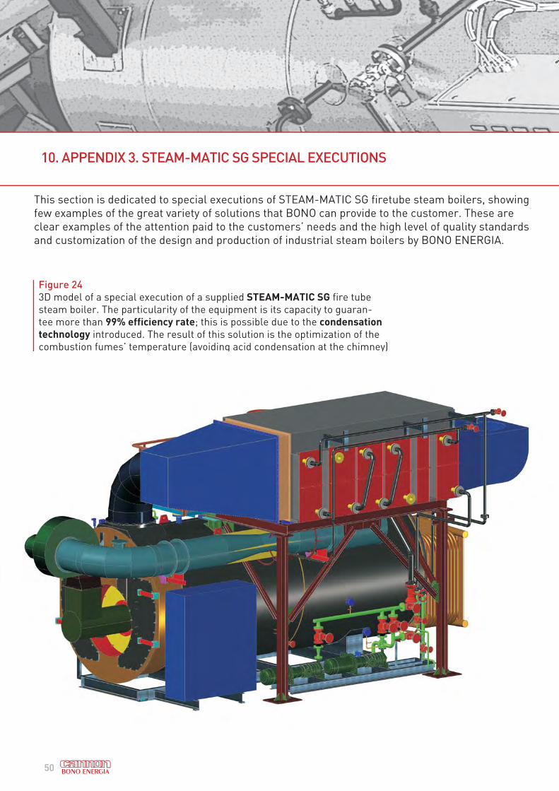
10. APPENDIX 3. STEAM-MATIC SG SPECIAL EXECUTIONS
This section is dedicated to special executions of STEAM-MATIC SG firetube steam boilers, showing
few examples of the great variety of solutions that BONO can provide to the customer. These are
clear examples of the attention paid to the customers’ needs and the high level of quality standards
and customization of the design and production of industrial steam boilers by BONO ENERGIA.
Figure 24
3D model of a special execution of a supplied STEAM-MATIC SG fire tube
steam boiler. The particularity of the equipment is its capacity to guaran-
tee more than 99% efficiency rate; this is possible due to the condensation
technology introduced. The result of this solution is the optimization of the
combustion fumes’ temperature (avoiding acid condensation at the chimney)
and the production of steam and hot water at a proper temperature accor-
ding to the brewing processes.

51
Figure 25
Picture of the supplied STEAM-MATIC SG fire tube steam boiler, with an effective steam
capacity of 20 ton/h at 15 bar, with efficiency rate above 99%. Field of application is a
brewery, the boiler can be fuelled with natural gas, heavy fuel oil and a combination of
natural gas and biogas, which is produced during the processes.

52
10. APPENDIX 3. STEAM-MATIC SG SPECIAL EXECUTIONS
Figure 26
3D drawings of STEAM-MATIC SG steam boilers, 20 t/h, 15 bar fuelled with
natural gas and heavy fuel oil. Each one of the three boilers is complete with
air preheaters, to achieve thermal efficiency up to 93%, and heat exchanger,
to produce superheated water from steam. The supply includes deaerator
and water treatment plant. This customized thermal plant’s field of applica-
tion is district heating.

53

54
STEAM BOILERS
» UNI-MATIC UM FLASH COIL STEAM GENERATORS Applications: food & beverage, textile industry,
plastics and rubber industry, woodworking, laundries
Steam production: from 0.3 to 3 t/h Pressure: up to 12 bar
» STEAM-MATIC SM and SG FIRE TUBE STEAM BOILERS Applications: pulp and paper industry, food &
beverage, district heating, plastics and rubber industry, chemicals and petrochemical industry, textile
Steam production: from 1 to 25 t/h Pressure: from 12 to 30 bar
» CLAJTUB CTD WATER TUBE STEAM BOILERS Applications: chemical processes, refinery,
petrochemical industry, power generation utilities, sugar refineries
Steam production: up to 180 t/h Pressure: up to 80 bar Temperature: up to 480 °C
» HRSG HEAT RECOVERY STEAM GENERATORS Applications: paper mill, chemical and
pharmaceutical, district heating, cogeneration, textile
Steam production: up to 40 MW From gas turbine: from 3 to 15 MW (el.), from engine: from 3 to 20 MW (el.)
STEAM-MATIC SG
CLAJTUB CTD
UNI-MATIC UM
11. APPENDIX 4. BONO ENERGIA PRODUCT RANGE

55
THERMAL FLUID HEATERS
» OIL-MATIC OMV THERMAL FLUID HEATERS, MULTI-COIL
TECHNOLOGY Applications: typography, cosmetics
industry, wood & paper, chemical industry, petrochemical
Thermal capacity: 0.2 to 6 MW Fluid temperature: up to 350 °C
» OIL-MATIC OMP THERMAL FLUID HEATERS, MULTITUBULAR Applications: pharmaceutical, petrochemical Thermal capacity: from 1.7 to 17 MW Temperature: up to 350 °C
» OIL-MATIC HTH HIGH TEMPERATURE THERMAL FLUID HEATERS Applications: district heating, oil & gas, others Thermal capacity: from 2 to 35 MW Temperature: up to 400 °C
SUPERHEATED WATER BOILERS
» CTH MULTITUBULAR SUPER HEATED WATER GENERATORS Applications: district heating and others Thermal capacity: up to 40 MW package: up to 80 MW - field erected Temperature: over 100 °C, up to 260 °C
» SM-ASA, SG-ASA FIRE TUBE SUPERHEATED WATER BOILERS Applications: district heating and others Thermal capacity: from 0.7 to 17 MW Temperature: over 100 °C
OIL-MATIC OMV
CTH
OIL-MATIC OMP

Bono Energia S.p.A
Via Resistenza 12 - 20068 Peschiera Borromeo (Mi) - Italy
Phone +39 0255302848 - Fax +39 025471955
www.bono.it
Ed. N°1
DISCLAIMER: All the data presented in this technical book are indicative and subject of changing due to
product customization and innovation processes.
They must be considered by the user only at the first stage of product selection; CANNON BONO declines
any responsibility for wrong usage of mentioned data and invites the user to contact our commercial
department for further details.