technical bulletin safety requirements for maintenance...
TRANSCRIPT

TB 385-4 ______________________________________________________________
TECHNICAL BULLETIN
SAFETY REQUIREMENTS FOR MAINTENANCE OF ELECTRICAL AND ELECTRONIC EQUIPMENT
This manual supersedes TB 385-4, dated 01 August 1992 DISTRIBUTION STATEMENT A- Approved for public release; distribution is unlimited. ____________________________________________________________
HEADQUARTERS, DEPARTMENT OF THE ARMY 01 JULY 2008


TB 385-4
i
Technical Bulletin No. 385-4
HEADQUARTERS, DEPARTMENT OF THE ARMY
WASHINGTON, DC 01 JULY 2008
SAFETY REQUIREMENTS FOR MAINTENANCE OF
ELECTRIC AND ELECTRONIC EQUIPMENT
REPORTING ERRORS AND RECOMMENDING IMPROVEMENTS You can help improve this manual. If you find any mistakes, or if you know of a way to improve the procedures, please let us know. Mail your letter or DA Form 2028 (Recommended Changes to Publications and Blank Forms) located in the back of this manual, directly to: Commander, U.S. Army CECOM Life Cycle Management Command (LCMC) and Fort Monmouth, ATTN: AMSEL-LC-LEO-E-ED, Fort Monmouth, NJ 07703-5006. You may also send in your recommended changes via electronic mail or by fax. Our fax number is 732-532-1556, DSN 992-1556. Our e-mail address is [email protected]. Our online web address for entering and submitting DA Form 2028s is http://edm.monmouth.army.mil/pubs/2028.html. This manual supersedes TB 385-4, dated 01 August 1992 DISTRIBUTION STATEMENT A- Approved for public release; distribution is unlimited.
TABLE OF CONTENTS
HOW TO USE THIS TECHNICAL BULLETIN ....................................................... iv CHAPTER 1 GENERAL INFORMATION .................................................................................... 1-1
Section 1.1 PURPOSE ........................................................................................................... 1-1 Section 1.2 SCOPE ................................................................................................................. 1-1 Section 1.3 CONSOLIDATED INDEX OF ARMY PUBLICATIONS AND BLANK FORMS . 1-1 Section 1.4 LIST OF ABBREVIATIONS/ACRONYMS ................................................ 1-1 Section 1.5 RESPONSIBILITIES ........................................................................................... 1-2 Section 1.6 STANDARD OPERATING PROCEDURES ........................................................ 1-3 Section 1.7 TRAINING ............................................................................................................ 1-3 Section 1.8 TECHNICAL ASSISTANCE ................................................................................ 1-3 Section 1.9 ACCIDENT REPORTING ................................................................................... 1-3 CHAPTER 2 EFFECTS OF ELECTRICAL CURRENT AND FIRST AID FOR ELECTRICAL SHOCK................................................................. 2-1 Section 2.1 INTRODUCTION ................................................................................................ 2-1 Section 2.2 PHYSIOLOGICAL EFFECT OF CURRENT FLOW ........................................... 2-1 Section 2.3 LETHAL EFFECT OF ELECTRICAL CURRENT .............................................. 2-2 Section 2.4 FIRST AID FOR ELECTICAL SHOCK VICTIMS ............................................... 2-2 CHAPTER 3 ELECTRONIC EQUIPMENT SAFETY REQUIREMENTS .................................... 3-1 Section 3.1 INTRODUCTION ................................................................................................ 3-1 Section 3.2 ELECTRICAL HAZARD TRAINING .................................................................. 3-1 Section 3.3 WORK PRACTICES FOR ELECTRICAL SAFETY ........................................... 3-2 Section 3.4 GENERAL PRECAUTIONS/WORK TECHNIQUES FOR ELECTRICAL SAFETY ............................................................................. 3-4 Section 3.5 USE OF EQUIPMENT ........................................................................................ 3-6 Section 3.6 OVERCURRENT PROTECTION ....................................................................... 3-7 Section 3.7 ELECTRICAL SERVICE FAILURE ................................................................... 3-7 Section 3.8 ELECTRICAL SAFETY EQUIPMENT ............................................................... 3-7 Section 3.9 GENERAL PROTECTIVE EQUIPMENT AND TOOLS ..................................... 3-11 Section 3.10 FACILITIES ........................................................................................................ 3-11 Section 3.11 CIRCUIT PANELS .............................................................................................. 3-13 Section 3.12 GROUND FAULT CIRCUIT INTERRUPTERS (GFCIS) .................................... 3-13 Section 3.13 FACILITIES FOR BATTERY CHARGING ......................................................... 3-13
TB 385-4
ii
Section 3.14 WARNING AND ALERTING TECHNIQUES ..................................................... 3-14 Section 3.15 WORK TECHNIQUES &GENERAL PRECAUTIONS FOR CECOM EQUIPMENT 3-14 CHAPTER 4 ELECTROMAGNETIC EQUIPMENT SAFETY REQUIREMENTS ....................... 4-1 Section 4.1 GENERAL INFORMATION ................................................................................ 4-1 Section 4.2 RESPONSIBILITIES OF COMMANDERS AND OTHER OFFICIALS .............. 4-1 Section 4.3 CALIBRATION OF INFRARED EQUIPMENT ................................................... 4-2 Section 4.4 HIGH INTENSITY LIGHT SOURCES ................................................................ 4-2 Section 4.5 CARBON ARCS ................................................................................................. 4-3 Section 4.6 HIGH INTENSITY LIGHT SAFETY PRECAUTIONS ......................................... 4-3 Section 4.7 LASERS ............................................................................................................. 4-4 Section 4.8 LASER SAFETY PRECAUTIONS ..................................................................... 4-4 Section 4.9 CLASS 3 AND 4 LASERS ................................................................................. 4-5 Section 4.10 CLASS 2 AND HIGHER LASER EQUIPMENT ................................................. 4-5 Section 4.11 RADIOFREQUENCY RADIATION (RFR) .......................................................... 4-6 CHAPTER 5 RADIOACTIVE MATERIAL SAFETY REQUIREMENTS ..................................... 5-1 Section 5.1 GENERAL INFORMATION ................................................................................... 5-1 CHAPTER 6 OTHER SAFETY REQUIREMENTS ..................................................................... 6-1 Section 6.1 GENERAL INFORMATION ................................................................................ 6-1 Section 6.2 SAFETY PRECAUTIONS .................................................................................. 6-1 Section 6.3 HAZARDOUS AND FLAMMABLE MATERIALS .............................................. 6-2 Section 6.4 CONTROL OF ACOUSTICAL NOISE ............................................................... 6-2
LIST OF TABLES Table 2-1 Thresholds Of Physiological Effects ................................................................. 2-3 Table 3-1 Restricted Approach Distances for Qualified Personnel ................................. 3-3 Table 3-2 Prohibited Distances ............................................................................................ 3-4 Table 3-3 Working Clearances ............................................................................................ 3-12
LIST OF ILLUSTRATIONS
Figure 3-1 Grounding Stick and Grounding Cable, Fabrication Diagram ........................ 3-9 Figure 3-2 Hook, Fabrication Diagram ................................................................................. 3-10 Figure 4-1 Class 3b and 4 Laser Controlled Area Warning Sign ....................................... 4-5 Figure 4-2 RFR Hazard warning Sign ................................................................................... 4-8

TB 385-4
HOW TO USE THIS TECHNICAL BULLETIN Bulletin Overview
The chapters within this manual are divided into specific functional information. Chapter types include General Information, Maintenance Information, and Supporting Information. Chapters are consecutively numbered using 4 digits starting with Chapter 1. Paragraphs are indicated by chapter, a decimal point and a number. For example, paragraph 1.1 is the first major paragraph in chapter 1, and paragraph 1.1.1 is the first subparagraph under paragraph 1 in chapter 1. Page numbers within each chapter are indicated by -1, -2, -3 (e.g., 1-1, (chapter 1, page 1)).
A glossary is provided for use in defining uncommon or inadequately defined terms. Warnings, Cautions and Notes
WARNING
Warning highlights an essential operating or maintenance procedure, practice, condition, statement, etc, which, if not strictly observed, could result in injury to, or death of, personnel or long term health hazards.
CAUTION Highlights an essential operating or maintenance procedure, practice, condition, statement, etc, which, if not strictly observed, could result in damage to, or destruction of, equipment or loss of mission effectiveness.
NOTE Highlights an essential operating or maintenance procedure, condition, or statement.
iii/(iv blank)


TB 385-4
CHAPTER 1 GENERAL INFORMATION
1-1
1.1 PURPOSE
The purpose of this bulletin is:
a. To provide guidance for electrical and electronic safety, consistent with the requirements of Federal law, to Army facilities,
b. To advise personnel who maintain electrical (excluding premises and utility wiring) and electronic equipment in Army facilities of precautions that will help them to work safely;
c. To advise commanders and other officials who exercise control over Army electrical and electronic maintenance activities of their essential safety responsibilities; and
d. To advise installation commanders of various safety and health-related responsibilities in supporting electrical and electronic maintenance activities.
1.2 SCOPE
1.2.1 What This Bulletin Covers. This bulletin covers safety precautions for all personnel - military, civilian, and contractor - who maintain electrical and electronic equipment in Army facilities. It includes wiring and maintenance for generators in use for powering type-classified military equipment. It specifically excludes premises wiring and permanently installed wiring as part of permanent structures. It excludes power distribution wiring provided by a utility to the premises. For safety guidance for working on premises wiring or power distribution refer to U.S. Army Corps of Engineers Manual No. 385-1-1, Safety And Health Requirements, and 29 CFR 1910 Subpart S, Occupational Safety and Health Standards, Electrical.
1.2.2 Additional Content. This bulletin also contains requirements for personnel safety indoctrination and training; medical surveillance programs; standard operating procedures; safety facilities; first aid; and coordination between maintenance activities and installation safety and health authorities that apply specifically to the maintenance of electrical and electronic equipment in Army facilities. 1.2.3 What This Bulletin Does not Cover This bulletin does not cover all safety precautions or responsibilities that may apply to any particular maintenance activity; rather, it includes only those that are widely applicable. It does not replace safety information published in system technical manuals. It does not cover safety procedures for work on power distribution systems or premises wiring. When establishing safety policy, commanders should consult with their installation safety office for further guidance.
1.3 CONSOLIDATED INDEX OF ARMY PUBLICATIONS AND BLANK FORMS
Refer to the latest issue of DA Pam 25-30 to determine whether there are new editions, changes, or additional publications pertaining to the equipment.
1.4 LIST OF ABBREVIATIONS/ACRONYMS
A ampere AC alternating current ANSI American National Standards Institute AR Army Regulation

TB 385-4
1-2
AWG American wire gauge Ci curie CECOM U.S. Army Communications-Electronics Command CFR Code of Federal Regulations CPR cardiopulmonary resuscitation CRT cathode ray tube DA Department of the Army dBA A-weighted decibels DC direct current DOD Department of Defense DODI Department of Defense Instruction DSN Defense Switched Network FM Field Manual GFCI Ground Fault Circuit Interruption HPD Hearing Protection Device Hz hertz LSO laser safety officer ma milliamperes MACOM major Army command MIL-HDBK Military Handbook ml milliliter NEC National Electrical Code NFPA National Fire Protection Association NRC Nuclear Regulatory Commission NSN National Stock Number para(s) paragraphs PEL permissible exposure limit RCA radiation controlled area REM roentgen equivalent man RF radiofrequency RFR radiofrequency radiation RMS root mean square RSO radiation safety officer SB Supply Bulletin SOP standard operating procedure TB Technical Bulletin TM Technical Manual TMDE Test, measurement, and diagnostic equipment W Watt
1.5 RESPONSIBILITIES
1.5.1 Installation Commanders. Installation commanders will provide health, safety, fire protection, engineering, and medical services to enable maintenance activities to fulfill their safety responsibilities. Installation services include the assistance of radiation protection officers as required by AR 700-64.
1.5.2 Radiation Protection Officers. Radiation protection officers will exercise the responsibilities listed in AR 11-9. Laser safety officers, if assigned, will exercise their specific responsibilities otherwise the listed responsibilities will be discharged by the radiation protection officer. 1.5.3 Commanders or Other Officials. Commanders or other officials who exercise operational control over maintenance activities will train all technicians and supervisors on the requirements of this bulletin, prepare and post safety standard operating procedures, provide safety training, and enforce the safety precautions prescribed herein. They will ensure that emergency kits and safety facilities, tests, surveys, warning signs, etc. are provided as needed. When applicable, and in coordination with the installation occupational health officer, they will enroll their personnel in medical surveillance programs; such programs are required in certain cases for personnel who may become exposed to the following hazards.

TB 385-4
1-3/(1-4 blank)
• Exposure to chemicals • ultraviolet, visible, or infrared radiation, including laser radiation • X-Ray radiation • acoustical noise
1.5.4 Supervisors and Technicians. Supervisors and technicians who maintain electrical or electronic equipment will observe the precautions prescribed herein and observe the warnings and precautions contained in the equipment technical manuals, including their test, measurement, and diagnostic equipment (TMDE) technical manuals. 1.5.5 All Personnel. Safety is everyone's responsibility.
1.6 STANDARD OPERATING PROCEDURES (SOPS)
Written SOPs are required for those frequently-performed hazardous operations so designated by the installation safety office. Additional SOPs will be prepared for maintenance of electromagnetic and radioactive equipment. All SOPs should be reviewed annually and updated as needed. Each initial SOP and changes or updates thereto shall be coordinated with the installation safety office and with the appropriate installation technical advisor, such as the radiation protection officer, post electrician, etc.
1.7 TRAINING
All personnel who work with electrical equipment and circuits who are exposed to an electrical hazard are required to be trained in accordance with paragraph 3.2.
1.7.1 Training Locations and Records. The required training shall be classroom or on-the-job type, or a combination of the two. Completion of the training, and completion of refresher training, shall be documented and maintained on file. Retention of training files for the duration of the personnel’s duties involving exposure to electrical/electronic work is recommended. 1.7.2 First Aid and Lifesaving. The commander will determine if personnel require training in first aid and lifesaving techniques, including rescue, mouth-to-mouth and cardiopulmonary resuscitation. Coordinate with local installation safety office and medical authorities for this determination.
1.8 TECHNICAL ASSISTANCE
Commanders and supervisors are encouraged to contact the installation safety office about safety and health questions and responsibilities. The safety office can provide needed information and recommend practical measures to enable everyone to safely do their job. If further information or assistance is needed, commanders and supervisors may contact the US Army Communications-Electronics Lifecycle Management Command (CELCMC) Directorate for Safety to discuss procedures to implement the safety precautions explained herein or to determine the advisability of waivers. To do so, write to Commander, US Army Communications Electronics Command and Fort Monmouth, ATTN: AMSEL-SF-S, Fort Monmouth, NJ 07703-5024, or telephone DSN 987-7445 or (732) 427-7445.
1.9 ACCIDENT REPORTING
Installation safety offices will report accidents that cause injury or equipment damage on DA Form 285, following the procedures prescribed in AR 385-40. Radiofrequency radiation and laser accidents will also be reported per Chapter 6 of AR 11-9. Accidents involving radioactive equipment will also be reported by telephone to the next higher headquarters and to the US Army Materiel Command.


TB 385-4
CHAPTER 2 EFFECTS OF ELECTRICAL CURRENTAND
FIRST AID FOR ELECTRICAL SHOCK
2-1
2.1 INTRODUCTION This chapter addresses the effects of electrical current on the human body and first aid for victims of electrical shock.
2.1.1 Contact With Live Electrical Circuits. Severe injury or death can result when any part of the human body comes in contact with live electrical circuits. Technicians must be especially alert to the dangers of exposed circuits, terminals, power entry panels, and the like. 2.1.2 Current and Voltage. The electrical phenomenon that injures and kills is CURRENT; the force that causes current to flow is called VOLTAGE. Voltage ratings are normally assigned to live electrical circuits, power supplies, and transmission lines. CONSIDER ALL VOLTAGES TO BE HAZARDOUS. Under certain conditions, even a low voltage can cause sufficient current to flow through the body to cause injury or death.
2.2 PHYSIOLOGICAL EFFECT OF CURRENT FLOW
2.2.1 Factors Influencing Current Through the Human Body. The physiological effect of current flowing through the human body is related to the following factors:
• The path of the current through the body.
• Magnitude of the current.
• Duration of the voltage shock or discharge that causes the current to flow.
• The frequency of the voltage if alternating current.
• Susceptibility of the heart to the current and to repeated shocks.
2.2.2 Physiological Effects of Current for Different Magnitudes and Frequencies. Table 2-1 displays the physiological effects of current for different magnitudes and frequencies of the applied voltage. At any specific frequency, rated in hertz (Hz), the current's effects become more severe as its magnitude increases. The same magnitude of current, measured in milliamperes (ma), will cause more severe effects at the lower frequencies than at the higher frequencies. 2.2.3 Ohms Law and the Human Body.
NOTE
Alternating current (AC) tends to concentrate near the body's surface because of the phenomenon of "skin effect". The higher the frequency of the AC voltage source, the more the current will tend to flow in or near the skin and away from internal body organs. Whereas the direct current (DC) resistance is a constant for a given set of physical conditions, the body's effective resistance to AC increases with frequency. A technical description of skin effect is in MILHDBK-419A, Volume 1, page 5-3.
2.2.3.1 Current Magnitude. The magnitude of the current is a function of both the applied voltage and the body's resistance and is determined by Ohm's Law: I = E/R, where I is the current flowing through the body, E is the voltage applied to the body, and R is the body's total resistance to the current flow, measured in ohms. Total body resistance, R, is the sum of contact (skin) resistance and internal body resistance.

TB 385-4
2-2
2.2.3.2 Contact Resistance. Contact resistance varies between 100 and 500 ohms. Wet skin presents lower resistance to voltage than dry skin. A larger contact area of skin presents less resistance than a small area. Under high voltage, contact resistance may break down and become negligible. 2.2.3.3 Internal Body Resistance. Internal body resistance normally varies between 200 and 1,000 ohms. Its magnitude depends in a large measure upon the frequency of the applied voltage. The lower the frequency of the applied voltage, the lower the effective internal body resistance and the higher the current flow around and through the heart and other vital body organs. In particular, the effects of any specific magnitude of current will be more severe at 60 Hz than at radio frequencies. 2.2.3.4 Prolonged Current Flow. Current's effect becomes more severe with the length of time that it flows through the body. Prolonged current flow can cause severe internal burns, collapse, unconsciousness, or death. Therefore, contact with a voltage source that may create a current above the let-go threshold is particularly dangerous.
2.3 LETHAL EFFECTS OF ELECTRICAL CURRENT
The lethal effects of electrical current on the human body are summarized below. The current values shown here and in Table 1 are approximations; different people have different thresholds of tolerance and there is not a precise value for a lethal exposure.
2.3.1 Currents Flowing Through the Heart. Currents flowing through the heart can cause ventricular fibrillation: rapid contractions of the muscle fibers of the heart and a lack of synchronization between the heartbeat and the pulse. Unless arrested, fibrillation may cause death within a few minutes. It is impossible to precisely know either the magnitude or the path that electrical current will take in any human body or whether that current will pass through the heart. However, be aware that 600 ohms of body resistance in contact with 120 volts will produce a current of 0.2 amperes somewhere in the body. The threshold for fibrillation can be as little as 0. 1 ampere. 2.3.1 Currents Flowing Through Chest, Head or Nerve Centers. Currents flowing through the chest, head, or nerve centers that control breathing can inhibit respiration and bring on suffocation. Paralysis of the respiratory organs may last for a considerable amount of time, even after the current is interrupted. In such event, artificial resuscitation must be promptly applied; see paragraph 2.4 below. High currents can cause the heart to stand still, produce fatal damage to the central nervous system, produce deep burns, and raise the body temperature to cause immediate death. Victims who have been revived sometimes die suddenly and without apparent cause. Reasons attributed to sudden death are aggravation of preexisting conditions, hemorrhages that affect vital nerve centers or produce other effects to the nervous system, burns, and other complications resulting from the shock.
2.4 FIRST AID FOR ELECTRICAL SHOCK VICTIMS
NOTE
DA PAM 40-11 stipulates that personnel who may be required to perform first aid must receive approved first-aid training as determined by the local medical authority. See DA PAM 40-11 .
For victims of electrical shock, prompt and appropriate first aid may mean the difference between life and death or between temporary and permanent injury. Many victims of electrical shock can be saved with proper and continued first aid. The importance of continuing cardiopulmonary resuscitation (CPR) in apparently dead victims cannot be overemphasized. Complete recovery of such victims has been achieved even after minutes of stopped or fibrillating heart action and cessation of breathing. All personnel working with electrical equipment must know how to apply CPR as described in FM 21-11 and be prepared to react to an electrical shock victim as follows:

TB 385-4
2-3/(2-4 blank)
a. Remove the victim from the source of current. If the victim can't let go of a live conductor, IMMEDIATELY KILL THE POWER OR PULL THE VICTIM AWAY, WHICHEVER IS FASTER. If pulling victim away, DON'T TOUCH THE VICTIM DIRECTLY. Instead, pull or pry the victim loose with a dry rope, wooden stick, or an insulated pole.
b. After removing the victim safely from the live conductor, seek medical help. If necessary, apply CPR and continue to do so until relieved by trained medical personnel.
c. Remember to kill the power if not done so previously.
NOTE
The threshold values in this table are approximations of average human tolerances. Actual tolerances vary from person to person
Table 2-1. Thresholds of Physiological Effects.
Physiological Effect Current (milliamperes)
Direct Current 60 Hz l0KHz Slight sensation on hand 0.6 0.3 5.0
Perception threshold, medium 3.5 0.7 8.0
Shock; no pain or loss of muscular control 6.0 1.2 11.0
Painful shock; slight loss of muscular control
41.0 6.0 37.0
Let-go threshold, median; painful shock 51.0 10.5 50.0
Severe shock; difficult breathing; near total loss of muscular control
60.0 15.0 63.0
fibrillation: (Probably fatal) 100


TB 385-4
CHAPTER 3 ELECTRONIC EQUIPMENT SAFETY REQUIREMENTS
3-1
3.1 INTRODUCTION This chapter summarizes essential electrical safety requirements for maintaining any type of electrical and electronic equipment. There are four subsections of electrical safety requirements: training, work practices for electrical safety, electrical safety equipment and facility requirements. Specific hazards inherent in CECOM equipment are also discussed. 3.2 ELECTRICAL HAZARD TRAINING All personnel exposed to electrical hazards shall receive training to identify electrical hazards. (Personnel exposed to electrical hazards do not include persons using electrical equipment in routine use.)
3.2.1 Electrical Hazard Training Requirements. This training shall include:
• For qualified persons:
o Work Practices for Electrical Safety (as detailed in this TECHNICAL BULLETIN).
o The skills and techniques necessary to distinguish exposed live parts from other parts of electric equipment.
o The skills and techniques necessary to determine the nominal voltage of exposed live parts, and the clearance distances specified in Table 3-1 and the corresponding voltages to which the qualified person will be exposed.
• For unqualified persons:
o Personnel who are not qualified persons but have duties in areas where they can encounter electrical hazards shall also be trained in and familiar with any electrically related safety practices not specifically addressed by this technical bulletin but which are necessary for their safety. (At minimum, recognition of electrical safety warning signs, location of shut-off switches and emergency call procedures.)
This training shall occur and be documented before personnel assumes duties exposing them to electrical hazards and annually thereafter.

TB 385-4
3-2
3.2.2 Job Briefing. Whenever work involves accessing energized parts, the person in charge shall conduct a job briefing with the personnel performing the work. The job briefing shall address:
• Hazards associated with the work.
• Procedures involved in the work.
• Any special precautions required to maintain electrical safety.
• Control of energy sources
• Personal protective equipment required for the work.
• Location of emergency/first aid equipment.
• Emergency call number and procedures.
• Location and procedure for emergency power disconnect.
One job briefing conducted before the start of the first job of the work day or shift shall meet the job briefing requirement for routine work and work that is repetitive and similar. For routine work, a brief discussion shall meet the requirement if the employee, due to training and experience, can reasonably be expected to recognize and avoid the hazards involved in the job.
3.3 WORK PRACTICES FOR ELECTRICAL SAFETY
3.3.1 Additional Job Briefings. Additional job briefings shall occur if any one of the following conditions exist.
• The work is new and unfamiliar,
• The work is complicated or incurs new electrical hazards, or
• The worker cannot be expected to recognize and avoid the hazards involved in the job. (In particular, this may apply to newly assigned personnel.)
3.3.2 Deenergization. The first choice in performing electrical work is to completely remove the electrical hazard, or deenergizing equipment. Deenergization will be the preferred method of establishing electrical safety and working on electrical equipment. Deenergization procedures will include:
• Determining all possible sources of electrical energy.
• Opening disconnecting devices/disconnecting power sources and verifying they are (electrically) open. Equipment shall be DISCONNECTED from power sources where possible.
• Preventing accidental/inadvertent reconnection of the equipment. For most equipment, removing the supply cable and keeping it in view/under control during maintenance is adequate. For larger equipment or permanently installed equipment, lockout/tagout may be necessary.
• Testing to verify deenergization. (Ensure test equipment is functioning properly by using a known voltage source before relying upon it for deenergization testing.)
• Grounding circuit parts before contact, where the possibility of stored or induced electrical energy exists. (For example, capacitors.) If induced energy is possible, the ground shall remain installed

TB 385-4
3-3
while the circuit parts are accessed. Equipment technical manuals will usually provide warnings if the possibility of stored or induced electrical energy exists.
3.3.3 Approach Boundaries. Only qualified personnel may access live electrical parts or approach electrical parts within the approach distances specified in Table 3-1.
NOTE
For the purposes of this table, no conductive object, tool, etc., may approach within the minimum approach distance.
Table 3-2. Restricted Approach Distances for Qualified Personnel.
Voltage range (phase to phase) Minimum approach distance 300V and less Avoid Contact
Over 300V, not over 750V 1 ft. 0 in. (30.5 cm).
Over 750V, not over 2kV 1 ft. 6 in. (46 cm).
Over 2kV, not over 15kV 2 ft. 0 in. (61 cm).
Over 15kV, not over 37kV 3 ft. 0 in. (91 cm).
Over 37kV, not over 87.5kV 3 ft. 6 in. (107 cm).
Over 87.5kV, not over 121kV 4 ft. 0 in. (122 cm).
Over 121kV, not over 140kV 4 ft. 6 in. (137 cm).
3.3.4 Unqualified Personnel...Unqualified personnel may not approach within 10 feet of energized exposed electrical parts nor bring any conductive object that approaches within 10 feet of exposed energized parts. If approach within these distances is required, the equipment shall be deenergized or appropriate Personal Protective Equipment or temporary insulating barriers shall be utilized.
3.3.5 Measurement of Energized Equipment. Where electrical measurements of energized equipment is required, insulating components of test equipment shall be construed as meeting the ‘avoid contact’ minimum approach requirement for under 300V, provided the test equipment is rated for that voltage. Voltage-rated gloves are RECOMMENDED but not required for these measurements. Otherwise, the equipment shall be deenergized to connect leads for measurement.
3.3.6 Warning Signs or Temporary Barriers. Warning signs or temporary barriers shall be installed in areas where energized electrical parts are exposed. Unqualified personnel will be escorted by a qualified person within this area. In a maintenance shop, where exposed energized parts are commonly encountered, permanent signs affixed to all entrances to the shop area shall meet the signage requirement. Warning signs shall be yellow and black with a CAUTION warning for areas that have exposed voltages from 50 to 600 volts. Areas that have exposed voltages exceeding 600 volts will be posted with red, white, and black DANGER signs. New signs should meet the ANSI Z535.2-2002 standard.

TB 385-4
3-4
3.3.7 Prohibited Distance.
NOTE
The following distances shown in Table 2 are construed as equivalent to contact and approach is prohibited for all personnel:
Table 3-3. Prohibited Distances.
Voltage range (phase to phase) Prohibited distance 300V and less Avoid Contact
Over 300V, not over 750V 0 ft. 1 in. (2.54 cm).
Over 750V, not over 15kV 0 ft. 7 in. (17.8 cm).
Over 15kV, not over 36kV 0 ft. 10 in. (25.4 cm).
Over 36kV, not over 46kV 1 ft. 5 in. (43.2 cm).
Over 46kV, not over 72.5kV 2 ft. 1 in. (63.5 cm).
Over 72.5kV, not over 121kV 2 ft. 8 in. (81.3 cm).
Over 121kV, not over 140kV 3 ft. 1 in. (94.0 cm).
3.3.8 Arc Flash Boundaries. Arc flash hazards are possible if work is conducted on energized electrical parts. An arc flash occurs when electrical parts are shorted and the resulting arc produces an intense flash of ultraviolet light, a shock wave from the arc and a spray of molten metal from the superheated metal parts. In general, arc flash hazards are prevalent on power circuits in excess of 600V. An arc flash boundary can exceed the approach distances for qualified, and in some cases unqualified workers. This is generally NOT the case for maintenance of electronic equipment, even those having higher voltages because the possible current is limited.
3.3.9 Arc Flash Boundaries on Power Sources up to 600V. For work on energized parts involving power sources up to 600V and equipped with circuit breaker devices the flash protection boundary shall be 4.0 feet. (Provided less than 50,000 ampere fault current is available for less than 0.1 second.) Adequate arc-flash protection is provided by wear of long-sleeved cotton-type shirts (uniform shirt or equivalent is adequate) and use of safety glasses.
3.3.8 Arc Flash Boundaries on Power Sources Over 600V. If work on energized parts is excess of 600V is required, the available fault current exceeds 50,000 amperes for a duration of more than 0.1 second, the equipment cannot be deenergized and the procedures/techniques for measurements on equipment in excess of 300V cannot be applied, an arc flash hazard analysis must be conducted to determine the appropriate Personal Protective Equipment (PPE) needed, if the appropriate PPE is not listed in the system Technical Manual. Arc flash hazard analysis will be conducted in accordance with the requirements of NFPA 70E, Electrical Safety in the Workplace. Contact the installation safety office for technical assistance if needed.
3.4 GENERAL PRECAUTIONS/WORK TECHNIQUES FOR ELECTRICAL SAFETY
3.4.1 Removal of Conductive Objects. Remove all jewelry, watches and other conductive items before commencing work on energized equipment. Conductive eyeglasses do not need to be removed. If a possible hazard is expected from wearing conductive eyewear, either nonconductive eyewear shall be worn or nonconductive goggles shall be worn over the eyewear.

TB 385-4
3-5
3.4.2 Required Personnel. At least two technicians must be in the immediate area at all times when work is being performed on exposed live circuits carrying 30 volts or more. Each technician must be able to see and hear the other technician. This ensures that one technician will be available to assist the other in case of an accident. Each technician shall know the location of, have unobstructed access to, and know how to function the power cutoff for the work area. 3.4.3 Hands, Feet, and Body. Be alert to the position of hands, feet, and body when working with energized circuit boards, power cables, transmitter output terminals, transmission lines, antennas, or any other kind of live circuit. Many electrical shock accidents during maintenance occur when one of the technician's hands contacts a live (hot) circuit while the other hand is touching a grounded conductor, such as a chassis, rack frame, or cable raceway. Make a habit of keeping one hand free. Experienced technicians use only one hand for probing while keeping the other hand in a pocket or behind the back. 3.4.3.1 Tasks Requiring Two Hands. When both hands are needed for such tasks as voltage measurements, firmly grasp the insulated leads and place them on the test points. When measuring, follow the procedures outlined below. Never work on energized parts when hands, feet, or body are wet or perspiring or when standing on a wet surface. 3.4.3.2 Touching Electrical Equipment. When a maintenance procedure requires touching electrical equipment in operation, such as checking for overheated motors, use the back of the hand. If an accidental shock were to occur, the hand will pull away rather than uncontrollably grasp the equipment. Never put hands on or near a capacitor or capacitor bank or any wire or conductor attached to a capacitor unless and until all the capacitors are grounded and a shorting bar or grounding stick is in place. 3.4.4 Emergency/Rescue Equipment. Know the location of emergency/rescue equipment and make sure that it is available. 3.4.5 Technique for Measuring Energized Equipment over 300V. Two technicians are needed for the following procedure.
a. Turn off all power to the equipment to be tested.
b. Discharge capacitors.
c. Attach a secure temporary ground to the equipment to be tested.
d. Attach plug-in or clip-on probes to the test points; hand held probes are not allowed for high voltage measurements.
e. Remove the ground installed in step c.
CAUTION
Do not touch the test instruments while the power is on.
f. Turn on the power and let the second technician take the readings.
g. Turn off the power.
h. Again discharge capacitors.
i. Remove the test leads.
j. If another measurement is required, repeat steps a through i.

TB 385-4
3-6
3.5 USE OF EQUIPMENT This paragraph applies to the use of cord and plug connected equipment, including flexible cord sets (extension cords) and test equipment. 3.5.1 Use of Equipment When Flammable Materials are Present. When flammable materials are present, electric equipment capable of igniting them shall not be used, unless measures are taken to prevent hazardous conditions from developing. 3.5.2 Flexible Cords and Portable Equipment. Hands must not be wet when plugging and unplugging flexible cords and connected equipment. Handle portable equipment and flexible cords in a manner which will not cause damage. 3.5.3 Defective or Damaged Equipment. When a defect or evidence of damage that can cause an electrical hazard is found, the defective or damaged item is non-mission capable. Use is prohibited until repairs and tests necessary to render the equipment safe are completed. 3.5.4 Portable Electric Equipment and Flexible Cords in Highly Conductive Work Locations. Portable electric equipment and flexible cords must be approved for use in highly conductive work locations such as those inundated with water or other conductive liquids, or in job locations where contact water or conductive liquids is likely. 3.5.5 Flexible Cords.
NOTE
Inspection of flexible cord sets (extension cords) which remain connected once they are put in place and are not exposed to damage is not required until they are relocated.
3.5.5.1 Prohibited use. Do not use flexible electric cords connected to equipment for raising or lowering the equipment. Do not fasten flexible cords with staples or hung in such a fashion as could damage the outer jacket or insulation. Flexible cords will not be used as permanent wiring.
3.5.5.2 Visual Inspection. Flexible cord sets (extension cords) shall be visually inspected before use on any shift for external defects such as damage to outer jacket or insulation and for evidence of possible internal damage such as pinched or crushed outer jackets. 3.5.5.3 Use with Grounding Type Equipment. A flexible cord used with grounding type equipment shall contain an equipment grounding conductor. 3.5.5 Attachment Plugs and Receptacles. Attachment plugs and receptacles must not be connected or altered in a manner which would prevent proper continuity of the equipment grounding conductor at the point where plugs are attached to receptacles. Attachment plugs and receptacles must not be altered to allow the grounding pole of a plug to be inserted into slots intended for connection to the current-carrying conductors. 3.5.6 Adapters. Adapters which interrupt the continuity of the equipment grounding connection are prohibited. 3.5.7 Attachment Plug. Before connecting an attachment plug on a cord set to a receptacle, ensure the relationship of the plug and receptacle contacts are of proper mating configurations. 3.5.8 Energized Plug and Receptacle Connections. Energized plug and receptacle connections shall be handled only with insulating protective equipment if the connection might expose personnel to an electrical hazard (for example, a cord connector is wet). 3.5.9 Locking Type Connectors. Locking type connectors shall be properly secured after connection.

TB 385-4
3-7
3.5.10 Opening, Reversing, or Closing of Circuits Under Load Conditions. Only devices specifically designed as disconnecting means shall be used for the opening, reversing, or closing of circuits under load conditions. Cable connectors not of the load break type, fuses, terminal lugs, and cable splice connections may not be used for such purposes. 3.5.11 Testing Equipment. Only qualified technicians may perform testing work on electric circuits or equipment. 3.5.12 Test Instruments and Equipment. Test instruments and equipment and all associated test leads, cables, power cords, probes, and connectors shall be visually inspected at least daily for external defects and damage before the equipment is used. When a defect or evidence of damage that can cause an electrical hazard is found, the defective or damaged item is non-mission capable. Use is prohibited until repairs and tests necessary to render the equipment safe are completed. Test instruments and equipment and their accessories shall be rated for the circuits and equipment to which they will be connected and shall be designed for the environment in which they will be used. Test equipment specified by system technical manual shall be considered as meeting this requirement. 3.5.13 Flammable Materials. Any time flammable materials are present, electric equipment capable of igniting them shall not be used, unless measures are taken to prevent hazardous conditions from developing. 3.6 OVERCURRENT PROTECTION 3.6.1 Circuit Deenergized by a Circuit Protective Device. If a circuit is deenergized by a circuit protective device, the circuit may not be manually reenergized until it has been determined that the equipment and circuit can be safely energized. 3.6.2 Repetitive Manual Reclosing. The repetitive manual reclosing of circuit breakers or reenergizing circuits through replaced fuses is prohibited.
3.6.3 Modifying or Bypassing Overcurrent Protection. Overcurrent protection of circuits and conductors may not be modified or bypassed, even on a temporary basis, unless directed by maintenance instructions in the system Technical Manual or those developed and approved under engineering supervision.
3.6.4 Failure Due to Overload. When it can be determined from the design of the circuit and the overcurrent devices involved that the automatic operation of a device was caused by an overload rather than a fault condition, no examination of the circuit or connected equipment is needed before the circuit is reenergized.
3.7 ELECTRICAL SERVICE FAILURE
In the event that electrical service fails while power is being applied to either the equipment being maintained or TMDE . . .
a. Open the circuit breakers of the power source, where practical.
b. Turn all equipment and TMDE power switches to the OFF position.
c. After service is restored, check that the equipment switches are in the OFF position before closing the circuit breakers.
3.8 ELECTRICAL SAFETY EQUIPMENT
3.8.1 Personal Protective Equipment (PPE). When working around potential electrical hazards, personnel shall be provided with, and shall use, electrical protective equipment that is appropriate for the specific parts of the body to be protected and for the work to be performed.
TB 385-4
3-8
3.8.2 Maintenance of PPE. Protective equipment shall be maintained in a safe, reliable condition and shall be periodically inspected or tested. If the insulating capability of protective equipment may be subject to damage during use, the insulating material shall be protected. (For example, an outer covering of leather is sometimes used for the protection of rubber insulating material.)
3.8.3 Nonconductive Head Protection. Always wear nonconductive head protection if there is a danger of head injury from electric shock or burns due to contact with exposed energized parts.
3.8.4 Eye and Face Protection. Always wear protective equipment for the eyes or face if there is danger of injury to the eyes or face from electric arcs or flashes or from flying objects resulting from electrical explosion.
3.8.5 Emergency/Rescue Equipment.
NOTE
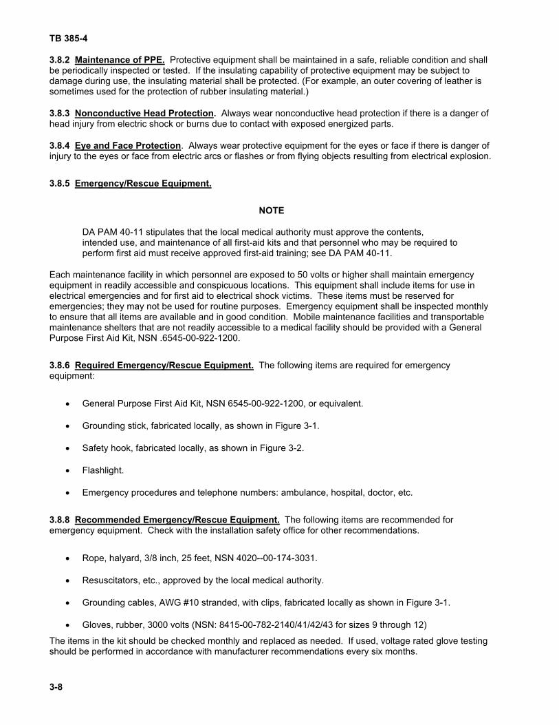
DA PAM 40-11 stipulates that the local medical authority must approve the contents, intended use, and maintenance of all first-aid kits and that personnel who may be required to perform first aid must receive approved first-aid training; see DA PAM 40-11.
Each maintenance facility in which personnel are exposed to 50 volts or higher shall maintain emergency equipment in readily accessible and conspicuous locations. This equipment shall include items for use in electrical emergencies and for first aid to electrical shock victims. These items must be reserved for emergencies; they may not be used for routine purposes. Emergency equipment shall be inspected monthly to ensure that all items are available and in good condition. Mobile maintenance facilities and transportable maintenance shelters that are not readily accessible to a medical facility should be provided with a General Purpose First Aid Kit, NSN .6545-00-922-1200.
3.8.6 Required Emergency/Rescue Equipment. The following items are required for emergency equipment:
• General Purpose First Aid Kit, NSN 6545-00-922-1200, or equivalent.
• Grounding stick, fabricated locally, as shown in Figure 3-1.
• Safety hook, fabricated locally, as shown in Figure 3-2.
• Flashlight.
• Emergency procedures and telephone numbers: ambulance, hospital, doctor, etc.
3.8.8 Recommended Emergency/Rescue Equipment. The following items are recommended for emergency equipment. Check with the installation safety office for other recommendations.
• Rope, halyard, 3/8 inch, 25 feet, NSN 4020--00-174-3031.
• Resuscitators, etc., approved by the local medical authority.
• Grounding cables, AWG #10 stranded, with clips, fabricated locally as shown in Figure 3-1.
• Gloves, rubber, 3000 volts (NSN: 8415-00-782-2140/41/42/43 for sizes 9 through 12)
The items in the kit should be checked monthly and replaced as needed. If used, voltage rated glove testing should be performed in accordance with manufacturer recommendations every six months.

TB 385-4
3-9
Figure 3-1. Grounding Stick and Grounding Cable, Fabrication Diagram

TB 385-4
3-10
Figure 3-2. Hook, Fabrication Diagram
TB 385-4
3-11
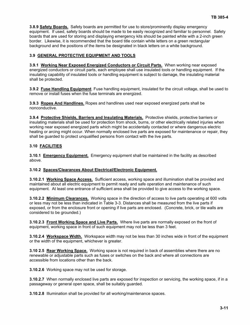
3.8.9 Safety Boards. Safety boards are permitted for use to store/prominently display emergency equipment. If used, safety boards should be made to be easily recognized and familiar to personnel. Safety boards that are used for storing and displaying emergency kits should be painted white with a 2-inch green border. Likewise, it is recommended that the board title contain white letters on a green rectangular background and the positions of the items be designated in black letters on a white background.
3.9 GENERAL PROTECTIVE EQUIPMENT AND TOOLS 3.9.1 Working Near Exposed Energized Conductors or Circuit Parts. When working near exposed energized conductors or circuit parts, each employee shall use insulated tools or handling equipment. If the insulating capability of insulated tools or handling equipment is subject to damage, the insulating material shall be protected. 3.9.2 Fuse Handling Equipment. Fuse handling equipment, insulated for the circuit voltage, shall be used to remove or install fuses when the fuse terminals are energized. 3.9.3 Ropes And Handlines. Ropes and handlines used near exposed energized parts shall be nonconductive. 3.9.4 Protective Shields, Barriers and Insulating Materials. Protective shields, protective barriers or insulating materials shall be used for protection from shock, burns, or other electrically related injuries when working near exposed energized parts which might be accidentally contacted or where dangerous electric heating or arcing might occur. When normally enclosed live parts are exposed for maintenance or repair, they shall be guarded to protect unqualified persons from contact with the live parts. 3.10 FACILITIES 3.10.1 Emergency Equipment. Emergency equipment shall be maintained in the facility as described above. 3.10.2 Spaces/Clearances About Electrical/Electronic Equipment. 3.10.2.1 Working Space Access. Sufficient access, working space and illumination shall be provided and maintained about all electric equipment to permit ready and safe operation and maintenance of such equipment. At least one entrance of sufficient area shall be provided to give access to the working space. 3.10.2.2 Minimum Clearances. Working space in the direction of access to live parts operating at 600 volts or less may not be less than indicated in Table 3-3. Distances shall be measured from the live parts if exposed, or from the enclosure front or opening if live parts are enclosed. (Concrete, brick, or tile walls are considered to be grounded.) 3.10.2.3 Front Working Space and Live Parts. Where live parts are normally exposed on the front of equipment, working space in front of such equipment may not be less than 3 feet. 3.10.2.4 Workspace Width. Workspace width may not be less than 30 inches wide in front of the equipment or the width of the equipment, whichever is greater. 3.10 2.5 Rear Working Space. Working space is not required in back of assemblies where there are no renewable or adjustable parts such as fuses or switches on the back and where all connections are accessible from locations other than the back. 3.10.2.6 Working space may not be used for storage. 3.10.2.7 When normally enclosed live parts are exposed for inspection or servicing, the working space, if in a passageway or general open space, shall be suitably guarded. 3.10.2.8 Illumination shall be provided for all working/maintenance spaces.

TB 385-4
3-12
3.10.2.9 Where provision of these working spaces is not practicable (for example on the interior of shelters or similar equipment), address the hazard in the job briefing and consider additional hazard controls, such as an assistant/safety watcher.
TABLE 3-3. Working Clearances
Minimum clear distance for condition (ft)
Nominal voltage to ground
(a)
(b)
(c)
0-150 3 3 3
151-600 3 3 ½ 4
601 to 2,500 3 4 5
2,501 to 9,000 4 5 6
9,001 to 25,000 5 6 9
25,001 to 75kV 6 8 10
Above 75kV 8 10 12
Conditions (a), (b), and (c), are as follows: (a) Exposed live parts on one side and no live or grounded parts on the other side of the working space, or exposed live parts on both sides effectively guarded by suitable wood or other insulating material. Insulated wire or insulated busbars operating at not over 300 volts are not considered live parts. (b) Exposed live parts on one side and grounded parts on the other side. (c) Exposed live parts on both sides of the workspace [not guarded as provided in Condition (a)] with the operator between. 3.10.3 Flooring And Work Surfaces.
NOTE
Wearing non-conductive safety shoes is recommended for personnel who work with dangerous voltages. Flooring must meet the one megohm per kilovolt resistance requirement whether or not safety shoes are worn.
Flooring and work surfaces should be constructed from non-conductive materials. In work areas with exposed voltages of 30 volts or more, resistance of flooring and work surfaces must be at least one megohm per kilovolt. Additional floor insulation such as rubber mats may be provided to achieve this level of resistance. 3.10.3.1 Flooring and Work Surface Test Schedule. New facilities will be tested before their initial use and annually thereafter to verify they meet the resistance requirement. A proper method for resistance testing is explained in paragraph 3.10.3.2. Test data and any corrective actions will be recorded and kept on file for two years.

TB 385-4
3-13
3.10.3.2 Surface Resistance Test Procedure. Resistance of floors and work surfaces shall be measured as described here or by an equivalent method approved by the installation engineer and safety office.
a. Select a high-resistance measuring instrument, such as the Biddle-Grey megohm meter, model no. 210359, NSN 6695-01-158-0747.
b. Connect one electrode of the measuring instrument to the facility's certified ground.
c. Connect the other electrode to a five-pound weight that has a contact surface of five square inches of good conducting material.
d. Attach a non-conductive strap or handle to the block.
e. Apply voltage
f. Pull the block along all points of the floor or work surface under test to verify that the complete surface meets the minimum resistance requirement of one megohm per kilovolt.
3.11 CIRCUIT PANELS Circuit panels, must be conspicuous and readily accessible with adequate working space and illumination. Each circuit on the panel must be clearly identified and prominently labeled. 3.12 GROUND-FAULT CIRCUIT INTERRUPTERS (GFCIS) 3.12.1 Where GFCIs Will be Used. GFCIs will be used where power outlets are required in damp or wet locations. GFCIs are strongly recommended for power outlets where live maintenance work is performed on cord-and-plug connected equipment. 3.12.2 GFCI Installation Verification. Verification of correct installation of GFCIs is required. Officials in charge of maintenance facilities should verify that the following initial test has been or is performed on each GFCI-protected circuit.
a. First, plug electrical equipment, such as a lamp or a radio, into the GFCI outlet, turn it on, and verify that it operates (receives power).
b. Then, press the Push-to-Test button on the receptacle. Verify that the equipment turns off and remains off, indicating that power has been removed.
c. Finally, press the Reset button on the GFCI. Verify that the equipment operates.
d. If pressing the "Push-to-Test" button does not interrupt power to the equipment, then ask the installation or facility electrician to check to see if the GFCI is correctly wired.
3.12.3 GFCI Test Schedule. In addition to this initial test, the "Push-to Test" button shall be tested monthly. Periodic testing with a GFCI tester is recommended to ensure the GFCI is functioning at the correct current levels. Defective GFCI receptacles shall be replaced. 3.13 Facilities For Battery Charging.
NOTE
Emergency eyewashes and showers must be certified to meet the requirements of American National Standards Institute (ANSI) Standard Z358.1.

TB 385-4
3-14
All facilities used for charging of batteries shall be well ventilated and equipped with readily accessible emergency eye wash and shower. The wash facility must be a type that can be easily operated by a blinded person and must function during the coldest time of year. It should be tested weekly. 3.14 WARNING AND ALERTING TECHNIQUES. The following alerting techniques shall be used to warn and protect employees from hazards which could cause injury due to electric shock, burns, or failure of electric equipment parts: 3.14.1 Safety Signs, Symbols, and Taggings. Safety signs, safety symbols, or accident prevention tags shall be used where necessary to warn employees about electrical hazards which may endanger them. Appropriate warning signs will be posted in areas where other hazards are known to exist. Warning signs may be required in the vicinity of toxic fumes, high-intensity visible light; X-Ray producing equipment; laser devices; radiofrequency (RF) equipment; and radioactive materials. 3.14.2 Barricades. Barricades shall be used in conjunction with safety signs where it is necessary to prevent or limit employee access to work areas exposing employees to uninsulated energized conductors or circuit parts. Conductive barricades may not be used where they might cause an electrical contact hazard. 3.14.3 Attendants. If signs and barricades do not provide sufficient warning and protection from electrical hazards, an attendant shall be stationed to warn and protect employees. 3.15 Work Techniques and General Precautions for CECOM Equipment This section discusses some hazards, techniques and precautions for use in the maintenance and servicing of CECOM equipment. 3.15.1 Use Of Grounding Sticks/Temporary Grounds. Grounding sticks and temporary grounds are intended to provide a safe means of short-circuiting an energized circuit. They are used especially to discharge residual energy stored in capacitors to ground and to provide an intentional short circuit to open circuit breakers in the event of accidental circuit energization. 3.15.1.1 Grounding Stick Construction. A typical grounding stick is illustrated in figure 3-1. The grounding stick conductor should be a solid copper hook of at least 3/16 inch diameter. The grounding stick handle may be made from rigid plastic or dry hardwood painted with clear shellac. The grounding stick may produce an electrical arc during the discharge process. 3.15.1.2 Grounding with a Grounding Stick. To use the grounding stick, the following procedures should be observed:
a. Ensure the correct is PPE available. Safety glasses or goggles and voltage-rated gloves may be required. Evaluate PPE required during the job briefing and follow any Technical Manual requirements or recommendations concerning PPE.
b. Visually inspect the stick before use. Look for cracks, damaged insulation and frayed wires. If damage is evident repair or replace the stick.
c. Connect the grounding stick to a known ground.
d. Touch the grounding stick to the component.
e. If possible, leave the grounding stick in place, or connect a temporary grounding jumper to help protect in the event of inadvertent energization. Ensure the jumper has sufficient capacity for the expected fault current.
f. Verify deenergization.

TB 385-4
3-15
3.15.2 X-radiation (X-ray) Hazards. Electrical equipment, including TMDE, that contain 10,000 volts or more may emit harmful x-rays. See Chapter 4 for precautions on the use or maintenance of equipment that emits x-rays. 3.15.3 Insulation Leakage. Promptly report and turn in for repair any electrically-powered equipment that causes a physical sensation when touched. The sensation is current leaking through the insulation. Insulation leakages become progressively worse and can become hazardous. Do not rely on grounding for protection against a defective circuit or wiring. 3.15.4 High-Voltage Capacitors. Fully discharge all high-voltage capacitors before starting work on or near the equipment in which they are contained. Some equipment has shorting bars installed that automatically discharge the capacitors when the chassis is opened. For equipment that does not automatically discharge, use grounding sticks for this purpose and leave them in place while maintenance work is being performed. This will prevent recharging of the capacitor from dielectric effect. 3.15.5 Cathode-Ray Tubes (CRTs). CRTs contain voltage hazards and can cause cuts and eye damage from implosion. Before handling an exposed CRT, short the high-voltage terminal to ground. Avoid scratching or damaging the CRT as this can cause implosion. Wear protective eye wear (such as safety glasses with side shields, industrial safety goggles, or a full face shield), leather gloves, and leather aprons when handling a CRT. 3.15.6 High-Voltage Vacuum Tubes. Be sure that the filaments are grounded before starting maintenance on any equipment that contains high voltage vacuum tubes used as rectifiers (e.g. 1B3GT, 1V2). While the power to the equipment is OFF, use an ohmmeter to check the filament ground circuits. 3.15.7. Components Containing Radioactive Material.
WARNING
If a radioactive component becomes broken, secure the area to prevent access. IMMEDIATELY notify the RSO or the installation safety office and follow their instructions.
Radioactive material is contained in some devices or commodities. For example, frequency standards, electron tubes (including spark gap), transmit/receive, glow lamps, voltage regulators, and cold cathode tubes may contain small amounts of radioactive material. Devices containing radioactive materials are normally identified and marked with a radiation warning symbol. Only conduct maintenance actions that are authorized in the system technical manual. In the event that an unmarked component is suspected of containing radioactive material, consult TB 43-0116 or contact the RSO for assistance. 3.15.8 Health Hazards of Selenium and Cadmium. 3.15.8.1 During soldering, selenium and polyfluoride dielectric material such as Teflon used in rectifiers and other semiconductors can release toxic fumes. These fumes have an odor similar to horseradish. If this odor is detected, turn off all power and evacuate the area until the fumes are ventilated. Repeated or prolonged inhalation of selenium fumes can cause severe breathing difficulties. Officials responsible for maintenance operations that might produce selenium fumes should have their operations surveyed by the installation industrial hygienist. 3.15.8.2 Skin contact with heated materials that contain selenium compounds can cause skin bums, rashes, or eye irritation. Use appropriate PPE when handling items that may have selenium compounds (i.e. heated selenium semiconductors.) 3.15.8.3 Cadmium is contained in some low-temperature silver solders and in certain metals. When heated, these materials can produce toxic fumes that irritate the nose and throat. Coughing, chest pains, sweating, chills, shortness of breath, or weakness may occur, even hours after exposure. Repeated or prolonged exposure can cause loss of sense of smell, emphysema, kidney damage, or anemia. Inhalation of a sufficient amount of cadmium, even over a short term, can cause death. Do not allow anyone to solder with materials that contain cadmium unless adequate ventilation systems are installed and properly functioning. Before

TB 385-4
3-16
working with cadmium compounds, check with local medical/industrial hygiene authorities. Medical surveillance may be required. 3.15.9 Removal of Vacuum Tubes. Vacuum tubes are removed with tube pullers. Do not use knives, screwdrivers, or other thin-edged tools. 3.15.10 Replacing Fuses. Before replacing fuses, disconnect the power and deenergize the circuits. Except for replacing fuses in holders that are designed to be removed by hand, use fuse pullers to remove and replace fuses. Do not replace a blown fuse with a fuse of a higher current rating or with a metal substitute. Fuses must be rated for the voltage to be applied to the circuit. Do not use a higher-rated fuse to correct a fault. Do not use a slow-blow fuse to replace a fast-blow fuse, and vice versa. Since a blown fuse is often the result of a circuit fault, check the circuit before replacing the fuse. 3.15.11 Alignment Tools and Hand Tools. Use only non-conductive alignment tools and hand tools with insulated handles in and around electrical or electronic circuits. 3.15.12 Soldering. Turn off soldering irons or place them in covered holders when they are unattended. Wear safety glasses or industrial safety goggles when soldering or unsoldering wires or components that are under tension. Molten solder may scatter when the wires or components break loose. 3.15.13 Solder Containing Cadmium. Use of silver solder containing cadmium is prohibited. If this work is required, coordinate with the installation safety office for approval. Special ventilation and industrial hygiene controls are needed to prevent inhalation of toxic cadmium fumes in this case. Personnel working with silver solder containing cadmium must receive periodic medical surveillance. 3.15.14 Bench Tops. Limit the number of electrically powered items, including TMDE, placed on the bench top and turned on during any maintenance operation to those necessary to perform the operation. Do not work with electrical equipment, tools, or TMDE on any bench that has a conductive (metal) surface. 3.15.15 Cables and Connectors. Turn off power before connecting or disconnecting cables to any power or signal source of 30 volts or more. Before using any cable or connector, inspect it for worn spots, breaks, cracks, and bent or broken pins. If a cable or connecter is defective, replace or repair it before proceeding. Always connect and disconnect cables by grasping end connectors. Never disconnect by pulling cable leads. 3.15.16 Storage Batteries.
WARNING
Know the location of the nearest eye wash and shower. If battery electrolyte is spilled on the skin or eye, immediately flush the area with a large quantity of water and continue flushing for fifteen minutes. Even a slight delay can mean loss of sight if the electrolyte contacts the eye. Immediately afterwards, go to the nearest medical treatment facility to get care that will be needed to prevent further damage.
CAUTION
To avoid back injury, use appropriate mechanical aids to lift large storage batteries.
3.15.16.1 Before Charging Batteries. The area should be well ventilated, clean, uncluttered, and free from unnecessary tools or conductive materials that could accidentally contact and short-circuit the battery terminals. 3.15.16.2 PPE for Filling Storage Batteries. Wear acid-resistant gloves, chemical-splash goggles, rubber aprons, and rubber boots with non-slip soles when filling storage batteries. If available, use a fume hood. 3.15.16.3 PPE While Charging. While working around batteries that are being charged, wear chemical-splash goggles or a full face shield to protect against sprayed electrolyte.

TB 385-4
3-17/(3-18 Blank)
3.15.17 Guards and Barriers. Do not remove any built-in guards or barriers in equipment that protect against accidental contact with a dangerous voltage within equipment unless its removal is necessary to test a circuit. If removal of a guard or barrier is necessary, replace it immediately after completing the maintenance task. 3.15.18 Interlocks. Never bypass interlocks designed to cut off power to a unit when access doors are opened except for interlocks containing a bypass switch or if power is needed for open-door testing. If the technical manual instructions require interlock bypass, always follow technical manual precautions and warnings. Do not rely on interlocks for disabling power. Always turn off the main power switch and disconnect the main power cord before opening equipment. 3.15.19 Vehicle Antennas. Make sure that mounted whip antennas can clear power lines before moving a vehicle. If practical, remove or tie down antennas. 3.15.20 Working Near Live Antennas And Other Sources Of Propagating RF Energy. Avoid contact with surrounding metal objects, such as railings, inactive antennas, equipment shelter walls, vehicles, aircraft, etc. If possible, ground all such objects that have not been grounded.

TB 385-4
CHAPTER 4 ELECTRONIC EQUIPMENT SAFETY REQUIREMENTS
4-1
4.1 GENERAL INFORMATION This chapter summarizes the essential safety responsibilities and precautions for maintaining equipment that generates energy in the electromagnetic spectrum. Electromagnetic equipment that generates or emits non-ionizing radiation (includes ultraviolet, infrared and high-intensity visible light, laser radiation; radiofrequency radiation (RFR); and ionizing radiation in the form of X radiation (X-rays). This chapter contains sections on commanders' responsibilities for electromagnetic equipment safety, safety precautions to observe while maintaining various types of electromagnetic equipments, and medical guidance for injuries from non-ionizing radiation. Further responsibilities of radiation protection officers (RPO) and laser safety officers (LSO) are explained in DA Pam 385-24. 4.2 RESPONSIBILITIES OF COMMANDERS AND OTHER OFFICIALS 4.2.1 Activities Servicing Any Type of Electromagnetic Equipment. Commanders or other officials of maintenance activities servicing any type of electromagnetic equipment shall coordinate with the installation RPO and occupational health officer to determine the need to enroll specific personnel in medical surveillance programs in accordance with DA Pam 385-24. 4.2.2 Activities Servicing or Using High Intensity Light Sources. Commanders or other officials of maintenance activities servicing or using high intensity light sources of the types identified in paragraph 4.4, High Intensity Light Sources, shall post appropriate warning signs in work areas and publish a safety SOP. If the maintenance activity services or uses carbon arcs, the activity commander or responsible official, in consultation with the installation safety office, shall ensure that work areas are properly ventilated; ventilation requirements are explained in paragraph 4.5, Carbon Arcs. 4.2.3 Activities Servicing Laser Equipment. Commanders or other officials of maintenance activities that service laser equipment shall:
• Publish an SOP that disseminates laser safety and first aid information in accordance with TB MED 524, and identifies the maintenance activity's program for laser safety indoctrination and training.
• Ensure that all rooms that are used for firing of a Class 4 laser device have door interlocks that disable the laser firing mechanism until the doors are closed.
• Ensure that appropriate caution or danger signs are posted at the entrances to laser firing areas.
• Ensure that laser maintenance facilities in which hazardous chemicals are used or stored contain an emergency eye wash and shower. The wash facility must be a type that can be easily operated by a blinded person, must function during the coldest time of year and it should be tested weekly.
• Ensure that maintenance facilities are adequately ventilated to exhaust
o the gases from gas lasers or the by-products of laser reactions, such as bromine, chlorine, or hydrogen cyanide.
o ozone created by laser-produced plasma.
o gases or vapors from cryogenic coolants.
TB 385-4
4-2
4.2.4 Activities Servicing Radiofrequency (RF) Equipment. Commanders or other officials of maintenance activities servicing radiofrequency equipment, such as radio transmitters and radars, shall . . .
• Publish an SOP that identifies, to the extent practical . . .
o restricted areas around transmitting antennas, feed horns, open wave guides, and other radiating devices.
o necessary precautions for safe entry of personnel into restricted areas
o and describes the maintenance activity's program for radiofrequency radiation (RFR) safety indoctrination and training.
• Ensure that all persons allowed access to areas where work is being performed on RF equipment are informed of RFR physiological effects and appropriate safety precautions explained in paragraph 4.11, Radiofrequency Radiation.
• Ensure that all conductive objects in RFR restricted areas, such as antenna masts and equipment shelters are properly grounded. See chapter 7, Facility Grounding Systems.
• Report to the installation Radiation Protection Officer (RPO) or occupational health officer all incidents of actual or suspected RFR overexposures. See paragraph 4.11, Radiofrequency Radiation.
4.2.5 Activities with X-ray Equipment or Electronic Devices Producing 10,000 Volts or More. Commanders or other officials of maintenance activities that servicing or using X-ray equipment or electronic devices producing 10,000 volts or more shall . . .
• Publish an X-ray safety SOP.
• Either verify that all such equipments and devices have been surveyed or arrange to have them surveyed to determine the extent of X-ray hazards, need for personnel dosimeters as required by DA Pam 385-24; and need for attaching warning labels.
• Implement, in coordination with the installation safety office, RPO, or industrial hygienist, appropriate X-ray safety measures, which might include posting of warning signs in the vicinity of X-ray hazards, installation of X-ray shielding, and the wearing of personnel dosimeters and instruction in their use
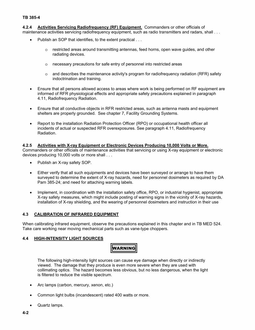
4.3 CALIBRATION OF INFRARED EQUIPMENT When calibrating infrared equipment, observe the precautions explained in this chapter and in TB MED 524. Take care working near moving mechanical parts such as vane-type choppers. 4.4 HIGH-INTENSITY LIGHT SOURCES
WARNING
The following high-intensity light sources can cause eye damage when directly or indirectly viewed. The damage that they produce is even more severe when they are used with collimating optics. The hazard becomes less obvious, but no less dangerous, when the light is filtered to reduce the visible spectrum.
• Arc lamps (carbon, mercury, xenon, etc.)
• Common light bulbs (incandescent) rated 400 watts or more.
• Quartz lamps.

TB 385-4
4-3
• Searchlight lamps.
• Lamps used as infrared sources.
• Solar simulators.
• Arc welding equipment.
• Electric arc furnaces.
• Germicidal lamps and other ultraviolet sources.
• High intensity light emitting diodes (LEDs) and LED arrays.
4.5 CARBON ARCS Carbon arcs used in welding and other applications generate hazardous ozone and oxides of nitrogen. These substances can cause headaches, vomiting, or in severe cases, permanent lung damage, pneumonia, or death. Work areas in which carbon arcs are operated must be ventilated by at least 10 room air changes per hour. Local exhaust ventilation of at least 100 feet per minute must be provided at the source of the hazardous gases. Because of the intensity of emitted radiation, safe operation of carbon arc equipment requires skin and eye protection. 4.6 HIGH-INTENSITY LIGHT SAFETY PRECAUTIONS Technicians and other personnel will observe the following precautions when maintaining an equipment or electronic component producing high intensity light. 4.6.1 Protective Eyewear.
WARNING
Immediately stop viewing any light source that causes eye discomfort, even if using protective eyewear.
Protective eyewear must be worn when working with a high intensity light source of any of the types identified in paragraph 4.4, High-Intensity Light Sources. Eyewear must provide protection at the specific wavelength of the light source and has an optical density no less than that specified in the equipment technical manual or recommended by the installation safety office. Be especially alert when working with searchlights, welding machines, and other infrared light sources. Infrared light is not visible and is hazardous. 4.6.2 Ventilation and Exhaust Fans. Both the room ventilation system and local exhaust fans must be turned on and properly functioning before operating carbon arc equipment 4.6.3 Personal Protection Equipment. Personal protection equipment for skin and eyes must be worn as specified in the SOP or by the installation safety office when working with carbon arc equipment. Personal protection equipment for welding includes leather welder's gloves, leather apron, safety shoes, and a welder's helmet. 4.6.4 Warning Signs. Warning signs must be posted in the work area before operating equipment containing a high intensity light source of any of the types identified in paragraph 4.4, High-Intensity Light Sources. 4.7 LASERS
NOTE

TB 385-4
4-4
Details on laser hazard classification are provided in Appendix D of TB MED 524.
General laser safety policy and requirements are specified by AR 11-9. Laser safety precautions are listed and explained in paragraph below. These precautions are summarized from TB MED 524 and the American National Standards Institute (ANSI) Z136.1, Safe Use of Lasers. For the purpose of hazard classification, laser devices are designated as either Class 1, 2, 3a, 3b, or 4, which have the following characteristics.
• Class 1 laser devices do not emit hazardous radiation.
• Class 1M laser devices do not emit hazardous radiation, unless viewed with an optical aid such as a magnifying optical instrument.
• Class 2 laser devices, which emit visible light, are not hazardous when viewed for less than 0.25 second, but can cause eye injury to a viewer who continuously stares at the direct beam. Protection of the eye is normally provided by aversion or blink response.
• Class 2M laser devices, which emit visible light, are not hazardous when viewed for less than 0.25 second, but can cause eye injury to a viewer who continuously stares at the direct beam. Also potentially hazardous if viewed with an optical aid such as a magnifying optical instrument. Protection of the eye is normally provided by aversion or blink response.
• Class 3R lasers may be hazardous under direct or reflection viewing conditions, particularly where the eye is focused upon the beam. Lasers given the older classification of IIIa may fall into this category.
• Class 3B lasers may be hazardous under direct or reflection viewing conditions.
• Class 4 lasers pose a hazard to the eye or skin from the direct beam, can pose a diffuse reflection hazard and can pose a fire hazard. They may also produce air contaminants.
4.8 LASER SAFETY PRECAUTIONS
Technicians and other personnel will observe the precautions listed in TB MED 524 when working with laser devices. A Nominal Hazard Zone (NHZ) analysis in accordance with ANSI Z.136.1 is required when Class 3B and Class 4 lasers are used outdoors, or anywhere (including laboratory/workshop use) where the beam path is accessible. 4.8.1 Laser Safety Precautions Specific to Maintenance and Laboratory Environments. Check the operator's technical manual for specific safety precautions before operating any laser device.
• Do not view or visually align laser beams or aim laser beams toward people.
• Operate laser devices only in well-lighted rooms. Good room lighting minimizes the opening of the pupil of the eye and reduces the potential for damage in the event of accidental exposure to the laser beam.
• Operate laser devices only for minimum time necessary to perform tests. Use laser illumination only for the purpose for which it is intended. Never use laser light for general illumination.
• Before operating a laser device, make sure that the room is properly vented and that all ventilation and exhaust systems are properly functioning. Keep as free of dust or airborne particles as possible.
4.8.1.1 Reflective Surfaces. Do not fire a laser upon any reflective surface. Reflected light from mirrors, glass, chrome, or other shiny surface is as dangerous to the unprotected eye as a direct exposure. Make sure that screens used for laser testing have a diffuse matte surface, preferably painted black and lusterless. Remove or cover reflecting surfaces such as brass door knobs, polished table tops, and glossy walls.

TB 385-4
4-5
4.8.1.2 Capacitors. Ensure that capacitors contained in laser devices are fully discharged before removing protective covers or panels. Be aware of the discharging method used in the device being maintained. This information is in the equipment technical manual. Capacitors are normally designed to self discharge either by an interlocking relay attached to the access cover or panel or by the equipment's OFF switch. Never attempt to defeat the interlock or otherwise open the laser device while capacitors remain charged. 4.9 CLASS 3 AND 4 LASERS
DANGER signs must posted near the door or entrance to a Class 3b or 4 laser firing area. Figure 4-1 is an example of a DANGER sign.
4-1. Class 3b and 4 Laser Controlled Area Warning Sign 4.9.1 Protective Masks and Goggles. Wear proper protective masks or goggles when in the vicinity of an operating Class 3b or 4 laser device. For instructions in selecting protective eyewear, see TB MED 524, ANSI Z136.1, or consult a supervisor or the laser safety officer. 4.9.2 Attending Personnel. Keep the number of people in a room where a Class 3 or 4 laser device is being tested to the minimum. Do not operate a Class 3b or 4 laser device until certain that all personnel and visitors present are wearing appropriate protective masks or goggles. 4.9.3 Laser Operating Conditions. Operate Class 3a, 3b and 4 lasers only in a closed room or in a light-tight box. Remote operation is preferred. Ensure the minimum distances and dimensions of the test range conform to the requirements of TB MED 524 before operating Class 3 a, 3b and 4 lasers. 4.10 Class 2 and Higher Laser Equipment
WARNING
Do not make direct eye contact with the beam of a Class 2 laser device.
4.10.1 Caution and Warning Labels. Verify that caution or warning labels are permanently affixed to all Class 2 or higher laser equipment. If any such laser equipment that does not contain a label, notify a supervisor or the laser safety officer. 4.10.2 Combustible Solvents and Materials. Do not operate Class 4 laser devices or power supplies around combustible solvents and materials. Combustible solvents and materials must be properly stored and handled.

TB 385-4
4-6
4.10.3 Cryogenic Gas Containers. Do not handle cryogenic gas containers in any room where lasers are being tested. See chapter 6, Pressurized Gas Cylinders Safety Precautions, on handling and storing pressurized gas cylinders and cryogenic gas containers. 4.10.4 Laser Activation Switches. Establish key control over keyed laser activation switches. Keyed activation is required on Class 4 laser devices. 4.10.5 Warning System. An activation warning system (visual and/or audible) is required for Class 3B and Class 4 lasers 4.11 RADIOFREQUENCY RADIATION (RFR) RFR safety precautions are listed below. These precautions are summarized from DOD Instruction (DODI) 6055.11 and the RFR hazard control measures in TB MED 523. DODI 6055.11 specifies a Permissible Exposure Limit (PEL) to RFR within which it remains safe to operate and maintain RF equipment.
WARNING
Exposure to RFR that exceeds the PEL can be hazardous. Excessive levels of RFR can cause localized heating of the skin, eyes, and other body tissue. The effects of prolonged exposure include eye cataracts and serious burns.
NOTE
The DoD-prescribed PEL to RFR is 0.4 watts per kilogram of whole-body absorbed power averaged over any six-minute period.
4.11.1 Hazard Distance. Hazard Distance is the minimum safe distances of separation from RFR emitters. Remain within the PEL by keeping proper hazard distance from RFR emitters. Areas that are less than the hazard distance should be designated as restricted and placed off limits to personnel while RFR is present. Minimum safe distances of separation from RFR emitters in Army electronic systems and other important guidance are specified in the operator's technical manuals. For many systems, this information can also be found in TB 43-0133. 4.11.2 Hazards to Fuel and Ordnance. Hazards of Electromagnetic Radiation to Ordnance (HERO) and Hazards of Electromagnetic Radiation to Fuel (HERF): Ordnance can be sensitive to RFR and voltages induced on metal parts in a RFR field can cause sparks that can ignite fuel vapor. 4.11.3 Equipment HERO Data. Determine HERO data for the equipment. This information can be found in system technical manuals. When in doubt, power down RFR emitters near ammunition and explosives. Blasting caps and similar devices are particularly sensitive to HERO effects. Percussion-initiated small arms ammunition is immune from HERO effects. 4.11.4 Equipment HERF Data. Determine HERF data for the equipment. This information can be found in system technical manuals. If the system output power exceeds 250 W, power down when within 50 m of fuelling operations. When in doubt, power down RFR emitters during fuelling operations. Diesel fuelling operations are immune to HERF effects. Fuelling operations using gasoline products, avgas, JP-4, propane, natural gas, etc., need consideration for potential HERF hazards. 4.11.5 RFR Safety Precautions. Technicians and other personnel will observe the following precautions when working with an equipment or electronic component that produces RFR. 4.11.5.1 Unnecessary Exposure. Avoid unnecessary exposure to RFR. Operate transmitters and other sources of RFR only when necessary and at minimum power and for the minimum period of time needed to maintain the equipment.

TB 385-4
4-7
4.11.5.2 Hazard Distance. Keep at least the specified minimum safe distance (hazard distance) away from antennas and other RFR sources. Consult the operator's technical manual to learn this distance. This information is in TB 43-0133 for many systems. 4.11.5.3 Unsecured Restricted Areas. Unsecured restricted areas shall be continuously monitored to prevent accidental entry. 4.11.5.4 Shock and Burn Danger. Be alert to the danger of shock and burns. Keep hands and body away from unprotected transmitter output terminals, uninsulated RF transmission lines, antennas, and other devices that may be carrying RF energy. Shock or burns can be caused by RF energy at any frequency; however, they are most likely to occur at frequencies between 3 kHz and 100 MHz. 4.11.5.5 Prohibited Actions. Do not transmit RFR within buildings, equipment shelters, or other enclosed environments unless the system is designed for this purpose. Do not aim antennas or propagate RFR toward populated areas. Except when necessary to test antennas, terminate RFR generators into a dummy load or another closed system. 4.11.6 Before Using Equipment Transmitting RFR. Inspect equipment interlocks and limiting and warning devices to make sure that they are properly functioning. If practical, make a record of the inspections. 4.11.7 Warning Signs. Post warning signs to point out the location of restricted areas. Appropriate types and locations for warning signs are explained TB MED 523. An example of an RFR warning sign is shown in fig. 4-2.
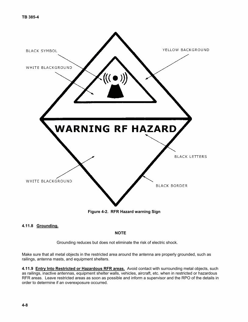
TB 385-4
4-8
Figure 4-2. RFR Hazard warning Sign
4.11.8 Grounding.
NOTE
Grounding reduces but does not eliminate the risk of electric shock.
Make sure that all metal objects in the restricted area around the antenna are properly grounded, such as railings, antenna masts, and equipment shelters. 4.11.9 Entry Into Restricted or Hazardous RFR areas. Avoid contact with surrounding metal objects, such as railings, inactive antennas, equipment shelter walls, vehicles, aircraft, etc. when in restricted or hazardous RFR areas. Leave restricted areas as soon as possible and inform a supervisor and the RPO of the details in order to determine if an overexposure occurred.

TB 385-4
4-9/(4-10 Blank)
4.11.10 Before Inspection of RFR Equipment Disconnect power to the transmitter before inspecting antennas, feed horns, open waveguides, and the like. Take steps to prevent an inadvertent connection of RF power, such as tagging or preventing access to the transmitter and power supply. 4.11.11 Before Using Installed Waveguides. Installed waveguides of any kind must be inspected for cracks and proper connections before use. If available, use an RFR leakage detector to check for leaks. (RFR leakage is more likely to occur in flexible waveguides than in rigid waveguides.) 4.11.12 During Maintenance of Aircraft Electronics. Antennas must be directed away from occupied areas when maintaining aircraft electronics. 4.11.13 Antenna Mast Clearance. Before erecting antenna masts, make sure that the clearance to nearby power lines is at least twice the length of the mast.


TB 385-4
CHAPTER 5
RADIOACTIVE MATERIAL SAFETY REQUIREMENTS
5-1/(5-2 blank)
WARNING
Do not touch a broken or unsealed radioactive item. Isolate the Area. Do not permit access. Immediately contact the Radiation Protection Officer or Installation Safety Office to obtain necessary procedures for safe decontamination and disposal of the radioactive material
5-1. GENERAL INFORMATION Radioactive safety precautions and handling and disposal procedures are contained in TM 3-261, and TB 43-0116. Responsibilities for Radiation Protection Officers are found in DA PAM 385-24. Always follow system technical manual instructions and precautions concerning radioactive material


TB 385-4
CHAPTER 6
OTHER SAFETY REQUIREMENTS
6-1
6.1 GENERAL
This section summarizes essential safety precautions not covered in the previous sections and requirements for storing hazardous and flammable materials and controlling acoustical noise while maintaining electrical and electronic equipments. 6.2 SAFETY PRECAUTIONS Technicians and other personnel will observe the following precautions when maintaining electrical and electronic equipment. 6.2.1 Acoustical Noise. Keep acoustical noise levels and the time of exposure to high noises to a minimum. Wear a proper hearing protection device (HPD), earplugs and/or noise muffs, when in an area of high acoustical noise (85 dBA or greater). If an appropriate HPD has not been provided, ask a supervisor. 6.2.2 Mercury. Avoid breaking any component that contains mercury, such as switches, batteries, or thermometers. If a spill occurs, do not touch or allow mercury to contact any part of the body. Mercury can cause headaches, nausea, diarrhea, and, in repeated or long-term exposure, loss of teeth and mental deterioration. Thoroughly wash hands or any part of the body that may have inadvertently come in contact with the spilled mercury. If skin becomes irritated and the irritation persists after washing, get medical attention. Immediately change any clothing that becomes contaminated. Contaminated clothing should normally be discarded; if it is to be laundered, special precautions are necessary to ensure that all the mercury is removed and to avoid contaminating other clothing or the laundry equipment. Consult installation safety office for further information. To minimize breathing of mercury fumes, stay out of the area of the spill until it is decontaminated. Contact the installation safety office to obtain instructions for decontamination. 6.2.3 Pressurized Gas Cylinders. Handle pressurized gas cylinders in accordance with Title 29 CFR 1910, Subpart M, and AR 700-68. All personnel who work with or handle pressurized gas cylinders will review AR 700-68 annually. Maintenance activities will maintain a record of these reviews.
• Secure cylinders to avoid accidental tipping. • Keep no more than two cylinders of the same gas at a work station at any one time. Remove the
cylinders from the work station when they are empty. Be careful when handling the empty cylinders as they may still contain a small amount of gas.
• Do not handle cryogenic gas containers in any room where lasers are being tested. • Store cryogenic gas containers in open and well ventilated areas. • Check container valves and seals regularly.
WARNING
Suffocation can result from displacement of oxygen by leaking cryogenic gases. When handling cryogenic gases, wear face shields, protective gloves, and three-quarter length smocks.
6.2.4 Cleaning Solvents. When cleaning equipment, consult the technical manual for recommended type(s) of cleaning solvent. Do not use highly toxic or flammable cleaning solvents that require special ventilation, such as carbon tetrachloride, trichloroethylene, and benzene. Do not use gasoline, benzene, ether, or any other type of flammable fluid to clean any type of electrical equipment. Do not use alcohol unless specified by the equipment technical manual. Flammable materials that do not require special ventilation may be used to clean nonelectrical equipment. Do not use flammable materials in the presence of electrical generators or other equipment that can cause sparks.

TB 385-4
6-2
6.2.5 Compressed Air Blowers. Use either rubber or another insulating material for hose lines for blowing out equipment. Keep air supplies free of water. Keep air pressure to a minimum. Do not allow air pressure to exceed 30 pounds per square inch. Do not use compressed air for cleaning floors. Do not blow compressed air onto any person, including oneself. 6.2.6 Foot Protection. When handling material that can injure feet, wear safety shoes that meet ANSI Standard Z41. Approved shoes will have "ANSI Z41" labeled or embossed thereon. The installation safety office can recommend the appropriate type of safety shoes for specific tasks. 6.3 HAZARDOUS AND FLAMMABLE MATERIALS Hazardous materials must be stored and handled in accordance with their Material Safety Data Sheets, Title 29 CFR 19 1 0, DOD Manual 4145.19-R- 1, and the applicable National Fire Prevention Association (NFPA) codes. Officials in charge of maintenance facilities must obtain the approval of the installation fire prevention officer before using or storing flammable materials, whether the materials are liquids, gases, or solids. Only the minimum quantity of flammable materials needed for immediate use should be stored at the maintenance facility. Store flammable material only in a cabinet of the type approved by the NFPA or in a flammable liquid store room that meets the requirements of Title 29 CFR 1910.106 and the NFPA Flammable and Combustible Liquids Code. Contact the installation safety office for specific information and guidance on these requirements. 6.4 CONTROL OF ACOUSTICAL NOISE Officials in charge of maintenance facilities must establish controls and procedures to minimize acoustical noise. They are responsible to ensure that persons who work in areas where the sound level is 85 dBA or greater are provided with hearing protection devices and receive pre-placement and periodic audiometric evaluations under the supervision of the installation medical authority. They must post warning signs in noise hazard areas to indicate that hearing protection is required.

TB 385-4
CHAPTER 7
GROUNDING SYSTEMS AND FIRE PROTECTION
7-1/(7-2 blank)
7.1. GENERAL INFORMATION This section summarizes grounding and fire protection requirements for maintenance facilities. 7.2. FACILITY GROUNDING SYSTEMS Facility grounding systems must be installed and maintained in accordance with recognized standards. The most authoritative and complete standard for grounding is the National Electrical Code (NEC), published by the National Fire Protection Association (NFPA) as NFPA Publication 70. (Copies of the NEC may be ordered from NFPA, P.O. Box 9101, Quincy, MA 02669-9101, telephone (617) 770-3000, www.nfpa.org ; payment is required.) Other sources for approved grounding techniques are MIL-HDBK-419A (Volume 2) and FM 11-487.4, both available through military publications channels. 7.2.1 Facility Grounding Points. All grounding points within a facility will be electrically continuous to a grounding (earth) electrode. The resistance measured from the facility's most remote grounding point to each electrode should not exceed two ohms. The resistance of the grounding electrode to earth should not exceed twenty-five ohms. 7.2.2 Grounding of Mobile Facilities. Mobile facilities will be grounded in accordance with its operating instructions. If used, the power generator will be grounded to a ground system. If the generator and vehicle are sited less than twenty-five feet apart, either a common ground will be used or the two ground systems will be connected with bare copper cable, AWG #6 or larger. If commercial power is used, the vehicle will be grounded to the commercial ground conductor at the first service disconnect. 7.2.3 Grounding Metal Frames. Metal frames of electric equipment and tools, such as handheld power tools, must be connected to a grounding conductor, i.e., they must contain a three wire power cord and plug. Portable tools that are protected by an approved insulation system (listed by Underwriter's Laboratory, or equivalent) need not be grounded. 7.2.4 Other Grounging Requirements. Maintenance activities will maintain a file of up-to-date descriptions of all facility grounding installations, such as construction specifications and drawings, blueprints, work orders, etc. Installation engineers or other qualified personnel (as determined by local policy) should annually inspect grounding systems for compliance with appropriate standards, including conductor continuity as described in paragraph 7.2 .1. Continuity inspections should be made with a low-resistance ohmmeter. 7.3 FIRE PROTECTION Facilities will maintain fire extinguishers that are rated for Class C fires. To ensure that fire extinguishers are maintained in proper working order, each facility will establish a program of regular inspection in coordination with the installation fire department.
WARNING
Use only a fire extinguisher that is rated for Class C fires on electrical fires; see para 7.3. Do not use soda acid, water, or foam extinguishers on electrical fires. Water and foam are conductive and can cause electrical shock.
In the event of fire: a. Kill the power to all circuits in the affected area.
b. Call the installation fire department.
c. To the extent that it is safe, control the fire until the firefighters arrive.


RECOMMENDED CHANGES TO PUBLICATIONS AND BLANK FORMS
For use of this form, see AR 25-30; the proponent agency is OAASA
Use Part II (reverse) for Repair Parts and Special Tool Lists (RPSTL) and Supply Catalogs/Supply Manuals (SC/SM).
DATE 30 August 2002
TO: ( Forward to proponent of publication or form) (Include ZIP Code) Commander, US Army CECOM LCMC ATTN: AMSEL-LC-LEO-E-ED Fort Monmouth, NJ 07703-5006
FROM: (Activity and location) (Include ZIP Code) Jane Q. Doe, SFC 1234 Any Street Anytown, AL 34565
PART I - ALL PUBLICATIONS (EXCEPT RPSTL AND SC/SM) AND BLANK FORMS PUBLICATION/FORM NUMBER TM 11-1234-567-14
DATE 16 Sep 2001
TITLE Operator, Field and Sustainment Support Maintenance Manual for Radio, AN/ABC-123
ITEM PAGE PARA- GRAPH LINE FIGURE
NO. TABLE RECOMMENDED CHANGES AND REASON 1 WP0005
PG 3 2 Test or Correctiive Action column should identify a different WP number.
TYPED NAME, GRADE OR TITLE Jane Q. Doe, SFC
TELEPHONE EXCHANGE/AUTOVON, PLUS EXTENSION 123-4567
SIGNATURE
DA FORM 2028, FEB 74 REPLACES DA FORM 2028, 1 DEC 68, WHICH WILL BE USED. APD V4.00

TO: ( Forward to proponent of publication or form) (Include ZIP Code)
FROM: (Activity and location) (Include ZIP Code)
DATE
PART II- REPAIR PARTS AND SPECIAL TOOL LISTS AND SUPPLY CATALOGS/SUPPLY MANUALS PUBLICATION/FORM NUMBER
DATE
TITLE
PAGE NO.
COLM NO.
LINE NO.
NATIONAL STOCK
NUMBER
REFERENCE
NO.
FIGURE
NO.
ITEM NO.
TOTAL NO. OF MAJOR
ITEMS SUPPORTED
RECOMMENDED ACTION
PART III - REMARKS (Any general remarks or recommendations, or s uggestions for improvement of publications and blank forms. Additional blank sheets may be used if more space is needed.)
TYPED NAME, GRADE OR TITLE
TELEPHONE EXCHANGE/AUTOVON, PLUS EXTENSION
SIGNATURE
APD V4.00

RECOMMENDED CHANGES TO PUBLICATIONS AND
BLANK FORMS For use of this form, see AR 25-30; the proponent agency is OAASA
Use Part II (reverse) for Repair Parts and Special Tool Lists (RPSTL) and Supply Catalogs/Supply Manuals (SC/SM).
DATE
TO: ( Forward to proponent of publication or form) (Include ZIP Code)
FROM: (Activity and location) (Include ZIP Code)
PART I - ALL PUBLICATIONS (EXCEPT RPSTL AND SC/SM) AND BLANK FORMS PUBLICATION/FORM NUMBER
DATE
TITLE
ITEM PAGE PARA- GRAPH LINE FIGURE
NO. TABLE RECOMMENDED CHANGES AND REASON
TYPED NAME, GRADE OR TITLE
TELEPHONE EXCHANGE/AUTOVON, PLUS EXTENSION
SIGNATURE
DA FORM 2028, FEB 74 REPLACES DA FORM 2028, 1 DEC 68, WHICH WILL BE USED. APD V4.00

TO: ( Forward to proponent of publication or form) (Include ZIP Code)
FROM: (Activity and location) (Include ZIP Code)
DATE
PART II- REPAIR PARTS AND SPECIAL TOOL LISTS AND SUPPLY CATALOGS/SUPPLY MANUALS PUBLICATION/FORM NUMBER
DATE
TITLE
PAGE NO.
COLM NO.
LINE NO.
NATIONAL STOCK
NUMBER
REFERENCE
NO.
FIGURE
NO.
ITEM NO.
TOTAL NO. OF MAJOR
ITEMS SUPPORTED
RECOMMENDED ACTION
PART III - REMARKS (Any general remarks or recommendations, or s uggestions for improvement of publications and blank forms. Additional blank sheets may be used if more space is needed.)
TYPED NAME, GRADE OR TITLE
TELEPHONE EXCHANGE/AUTOVON, PLUS EXTENSION
SIGNATURE
APD V4.00

By Order of the Secretary of the Army: GEORGE W. CASEY, JR
General, United States Army Chief of Staff
0813503
JOYCE E. MORROW Administrative Assistant to the
Secretary of the Army
Official:
DISTRIBUTION: To be distributed in accordance with the initial distribution number (IDN) 340534 requirements for TB 385-4.


PIN: 009464-000