technical committee audiovisual multimediajun 02, 1997 · forum nor the publisher make any...
TRANSCRIPT

Technical CommitteeAudiovisual Multimedia
Services :Video on DemandSpecification 1.1
af-saa-0049.001
March, 1997

VoD Specification 1.1 af-saa-0049.001
ATM Forum Technical Committee Page ii
(C) 1997 The ATM Forum. All Rights Reserved. No part of this publication may bereproduced in any form or by any means.
The information in this publication is believed to be accurate as of its publication date. Suchinformation is subject to change without notice and the ATM Forum is not responsible forany errors. The ATM Forum does not assume any responsibility to update or correct anyinformation in this publication. Notwithstanding anything to the contrary, neither The ATMForum nor the publisher make any representation or warranty, expressed or implied,concerning the completeness, accuracy, or applicability of any information contained in thispublication. No liability of any kind shall be assumed by The ATM Forum or the publisheras a result of reliance upon any information contained in this publication.
The receipt or any use of this document or its contents does not in any way create byimplication or otherwise:
• Any express or implied license or right to or under any ATM Forum member company’spatent, copyright, trademark or trade secret rights which are or may be associated with theideas, techniques, concepts or expressions contained herein; nor
• Any warranty or representation that any ATM Forum member companies will announceany product(s) and/or service(s) related thereto, or if such announcements are made, thatsuch announced product(s) and/or service(s) embody any or all of the ideas, technologies,or concepts contained herein; nor
• Any form of relationship between any ATM Forum member companies and the recipientor user of this document.
Implementation or use of specific ATM standards or recommendations and ATM Forumspecifications will be voluntary, and no company shall agree or be obliged to implementthem by virtue of participation in the ATM Forum.
The ATM Forum is a non-profit international organization accelerating industry cooperationon ATM technology. The ATM Forum does not, expressly or otherwise, endorse orpromote any specific products or services.

VoD Specification 1.1 af-saa-0049.001
ATM Forum Technical Committee Page iii
TABLE OF CONTENTS
1. Introduction_______________________________________________ 3 01.1 Purpose ____________________________________________________________30
1.2 Scope ______________________________________________________________30
1.3 Document Organization _______________________________________________30
1.4 Terminology ________________________________________________________301.4.1 Acronyms ____________________________________________________________________ 301.4.2 Definitions____________________________________________________________________ 301.4.3 Data Unit Naming Convention____________________________________________________ 30
1.5 Related Documents ___________________________________________________301.5.1 Normative References ___________________________________________________________ 30
2. Video-on-Demand Serv ice Definition and Description [Informative]___ 3 02.1 Definition [Informative]________________________________________________30
2.2 General Description [Informative]________________________________________30
3. Video on Demand Serv ice Configuration [Informative] _____________ 3 03.1 User Plane Reference Configuration [Informative] ___________________________30
3.2 Control Plane Reference Configuration [Informative] ________________________30
3.3 Management Plane Reference Configuration [Informative]____________________30
4. VoD System Structure / Protocol Reference Model [Normative]______ 3 04.1 VoD Protocol Reference Model [Normative] _______________________________30
4.1.1 ATM Control Plane Protocol Reference Model [Normative]_____________________________ 304.1.2 ATM User Plane Protocol Reference Model [Normative] _______________________________ 30
4.2 Client-Server Architecture [Informative] __________________________________30
5. Network Adaptation [Normative] ______________________________ 3 05.1 Base level of N=2 [Normative] __________________________________________30
5.2 AAL-5 Action on Corrupted PDUs [Normative] ____________________________30
6. Traffic Parameters [Normative] _______________________________ 3 06.1 Interfaces/ Connections Summary [Informative] ____________________________30
6.2 ATM Layer Traffic Description [Normative] _______________________________306.2.1 Relationship between the MPEG-2 SPTS rate and ATM cell rate [Informative]______________ 306.2.2 ATM Layer Traffic Shaping [Normative]____________________________________________ 306.2.3 ATM Layer Traffic Contract Parameter - CDVtolerance [Normative] ________________________ 30
7. Quality of Service Parameters [Normative] ______________________ 3 07.1 ATM Layer QoS Parameters [Normative]_________________________________30
7.1.1 Delay Parameters [Normative] ____________________________________________________ 307.1.2 Accuracy and dependability parameters [Normative]____________________________________ 30
8. Connection Control [Normative] ______________________________ 3 08.1 Network Assumption [Normative] _______________________________________30

VoD Specification 1.1 af-saa-0049.001
ATM Forum Technical Committee Page iv
8.2 SVC(s) Connection Setup Capabilities [Normative]__________________________308.2.1 First Party Connection Reference Model [Informative]__________________________________ 308.2.2 Proxy Signaling Connection Model [Informative] _____________________________________ 308.2.3 Proxy Signaling when Server supports signaling, but Client does not [Informative] __________ 308.2.4 Proxy Signaling when Client supports signaling, but Server does not. [Informative]__________ 30
8.3 ATM Signaling Requirements [Normative] ________________________________308.3.1 Interfaces / Connections [Informative] ______________________________________________ 308.3.2 ATM Signaling Information Elements Required [Normative] ____________________________ 308.3.3 ATM Signaling Information Elements Coding Requirements [Normative]__________________ 30
8.3.3.1 AAL Parameters I.E. [Normative]_____________________________________________ 308.3.3.2 ATM Traffic Descriptor I.E. [Normative]________________________________________ 308.3.3.3 Broadband bearer capabilities I.E. [Normative]____________________________________ 308.3.3.4 Broadband Higher layer information I.E. [Normative] ______________________________ 308.3.3.5 QOS Parameters I.E. [Normative]_____________________________________________ 308.3.3.6 Generic Identifier Transport I.E. [Normative]_____________________________________ 308.3.3.7 Other Information Elements [Normative]________________________________________ 30
9. Session Control [Informative] ________________________________ 3 0
ANNEXES
Annex A Jitter [Informative] . . . . . . . . . . . . . . . . . . . . . . . . . . . . . . . . . . . . . . . . . . . . . . . . . . . . . . . . . . . . . . . . . . . . . . A-1
Annex B Example Networks [Informative] . . . . . . . . . . . . . . . . . . . . . . . . . . . . . . . . . . . . . . . . . . . . . . . . . . . . . B-1
Annex C AMS QoS Parameters in Relation to ATM Layer QoS Parameters [Informative]C-1
Annex D Cell Delay Variation Tolerance [Informative] . . . . . . . . . . . . . . . . . . . . . . . . . . . . . . . . . . . . . . . D-1
Annex E Proxy Signaling Capability [Informative] . . . . . . . . . . . . . . . . . . . . . . . . . . . . . . . . . . . . . . . . . . . . E-1
Annex F VoD Service Attributes [Informative]. . . . . . . . . . . . . . . . . . . . . . . . . . . . . . . . . . . . . . . . . . . . . . . . . F-1
Annex G Interim Connection Management Arrangements Prior to ATM Forum Signaling4.0 [Informative]. . . . . . . . . . . . . . . . . . . . . . . . . . . . . . . . . . . . . . . . . . . . . . . . . . . . . . . . . . . . . . . . . . . . . . . . . . . . . . . . . . . . .G-1
VoD Specification 1.1 af-saa-0049.001
ATM Forum Technical Committee Page 1
Introduction
Purpose
This document specifies the ATM Forum’s Implementation Agreement for the carriage ofaudio, video, and data over ATM in support of Audio-visual Multimedia Services (AMS).
ScopeThis Implementation Agreement addresses the carriage of MPEG-2 bit streams over ATM.
Phase 1 of this specification specifically addresses the requirements of Video on Demandusing Constant Packet Rate (CPR) MPEG-2 Single Program Transport Streams (ISO/IEC 13818-1).
Phase 1 specifies:• AAL requirements.• the encapsulation of MPEG-2 Transport Streams into AAL-5 PDUs.• the ATM signaling and ATM connection control requirements.• the traffic characteristics.• the Quality of Service characteristics.
The service profiles provide information on:• Reference models for the service• Parameter values for the carriage mechanism for the provision of the service.
This phase 1 specification will provide informational material on Service Profiles; i.e.,VoD in phase 1. Later phases may include other retrieval services, conversationalservices, and high-quality broadcast.
Document Organization
Section 1 provides introductory material on scope, purpose, terminology and references.Section 2 provides information about the Video on Demand service. Section 3 providesinformation about the Video on Demand service configuration and scenarios expected.Section 4 specifies the System Structure / Protocol Reference Model. Section 5 specifiesthe Network Adaptation. Section 6 specifies the traffic parameters used . Section 7specifies the QoS parameters used. Section 8 provides information and specifications onconnection control. Section 9 provides information concerning session control.
Informative Annexes are provided on jitter, example networks, relating AMS QoSparameters to ATM layer QoS parameters, Cell Delay Variation Tolerance, proxy signalingcapability , VoD service attributes and interim signaling arrangements.
Each following section of the document (after section 1) is marked as [Informative] or[Normative]. Compliance with this specification requires compliance with the sectionsmarked as [Normative].

VoD Specification 1.1 af-saa-0049.001
ATM Forum Technical Committee Page 2
Terminology
AcronymsAAL.............................ATM Adaptation LayerADSL...........................Asymmetric Digital Subscriber LoopAMS ............................Audio-visual Multimedia ServicesATM ............................Asynchronous Transfer Mode
BICI .............................Broadband Inter-Carrier Interface
CBR.............................Constant Bit RateCDV.............................Cell Delay VariationCER.............................Cell Error RateCLR.............................Cell Loss RatioCMISE .........................Common Management Information Service ElementCPCS...........................Common Part Convergence SublayerCPR.............................Constant Packet RateCTD.............................Cell Transfer Delay
DSM-CC.......................Digital Storage Media Command and ControlDSM-CC U-N................DSM-CC User to NetworkDSM-CC U-U................DSM-CC User to User
ECBR...........................Errored Cell Block Rate
FTTC ...........................Fiber To The CurbFTTH ...........................Fiber To The House
GCRA ..........................Generic Cell Rate Algorithm
IE ................................. Information Element(s)ILMI .............................Interim Local Management InterfaceIWU..............................Inter Working Unit
HDT .............................Head-end Distribution TerminalHFC .............................Hybrid Fiber/Coax
LEC ..............................Local Exchange Carrier
MECBC.........................Maximum Errored Cell Block CountMPEG .........................Moving Pictures Experts GroupMPEG2-PCR.................MPEG-2 Program Clock Reference
NPC .............................Network Parameter ControlNSAP............................Network Service Access PointNVoD............................Near Video-on-Demand
ONU .............................Optical Network UnitOSI...............................Open Systems Interconnection
PC ...............................Personal ComputerPCI ..............................Protocol Control InformationPCR.............................Peak Cell Rate
VoD Specification 1.1 af-saa-0049.001
ATM Forum Technical Committee Page 3
PDU .............................Protocol Data UnitPDV .............................PDU Delay VariationPES .............................Packetized Elementary StreamPS ...............................Program StreamPSA .............................Proxy Signaling Agent
QoS ..............................Quality of Service
ROT .............................Receive Only Terminal
SAAL...........................Signaling ATM Adaptation LayerSAP .............................Service Access PointSAR.............................Segmentation And ReassemblySC ...............................Service ComponentSDU .............................Service Data UnitSECBR..........................Severely Errored Cell Block RatioSNMP...........................Simple Network Management ProtocolSOT..............................Send Only TerminalSPTS ............................Single Program Transport StreamSSCF ............................Service Specific Convergence FunctionSSCOP..........................Service Specific Connection Oriented ProtocolSTT ..............................Set Top Terminal
TCP/IP .........................Transport Control Protocol / Internet ProtocolTS ...............................Transport Stream
UDP/IP.........................User Datagram Protocol / Internet ProtocolU-N..............................User to NetworkUNI..............................User to Network InterfaceUPC.............................Usage Parameter ControlU-U..............................User to User
VC...............................Virtual ConnectionVIP ...............................Video Information ProviderVoD..............................Video-on-DemandVPCI.............................Virtual Path Connection IdentifierVPI...............................Virtual Path Identifier
Definitions
MPEG-2 . . . . . . .ISO/IEC 13818-x series specifications
Session. . . . . . . . .association between two or more users, providing the capability to grouptogether the resources needed for an instance of a service
SPTS . . . . . . . . . .A Single Program Transport Stream is an MPEG-2 compliant transportstream that contains a single program. Because it contains only a singleprogram, an SPTS is referenced to a single time base. The time base isencoded into the SPTS using MPEG2-PCRs. An SPTS may containmultiple elementary streams. If the elementary streams require synchronizedpresentation, they reference the single timebase provided by the commonMPEG2-PCRs.

VoD Specification 1.1 af-saa-0049.001
ATM Forum Technical Committee Page 4
Data Unit Naming Convention
The data unit naming conventions are adopted from Annex A/ I.363 [8].
Related Documents
Normative References
[1] ATM Forum, “ATM User-Network Interface Specification 3.0”
[2] ATM Forum, “ATM User-Network Interface Specification 3.1”
[3] ATM Forum, “Signaling 4.0 Specification”
[4] ATM Forum, “Traffic Management 4.0 Specification”
[5] ISO/IEC IS 13818-1 | ITU-T Recommendation H.222.0 , “Information Technology -Generic Coding of Moving Pictures and Associated Audio - Part 1: Systems ”
[6] ITU-T Recommendation H.222.1, “Multimedia Multiplex and Synchronization forAudiovisual communication in ATM environments”
[7] ITU-T Recommendation H.310, “B-ISDN Audiovisual Communications Systemsand Terminals”
[8] ITU-T Recommendation I.363, “B-ISDN ATM Adaptation Layer (AAL)Specification”
[9] ATM Forum, “Native ATM Services: Semantic Description, Version 1.0”
[10] ISO/IEC DIS 13818-6 , “Information Technology - Generic Coding of MovingPictures and Associated Audio - Part 6: MPEG-2 Digital Storage Media - Commandand Control (DSM-CC) ”
[11] ISO/IEC IS 13818-2 | ITU-T Recommendation H.262 , “Information Technology -Generic Coding of Moving Pictures and Associated Audio - Part 2: Video ”
[12] ISO/IEC IS 13818-3, “Information Technology - Generic Coding of Moving Picturesand Associated Audio - Part 3: Audio
[13] ITU-T Recommendation E.164, “Numbering Plan for the ISDN Era”
[14] ITU-T Recommendation F.722, “Broadband Videotelephony Services”
[15] ITU-T Recommendation I.211, “Integrated Services Digital Network GeneralStructure and Service Capabilities - B-ISDN Service Aspects”.
[16] ITU-T Recommendation H.245, “Line Transmission of Non-Telephone Signals -Control Protocol For Multimedia Communication”
[17] ITU-T Recommendation Q.2931, “B-ISDN DSS2 UNI Layer 3 Specification forBasic Call/Connection Control”
[18] ITU-T Recommendation I.356, “B-ISDN ATM Layer Cell Transfer Performance”
[19] ITU-T Recommendation I.371, “Traffic Control and Congestion Control in B-ISDN”.
[20] ITU-T Recommendation Q.2110, “B-ISDN ATM Adaptation Layer ServiceSpecific Connection Oriented protocol (SSCOP)”

VoD Specification 1.1 af-saa-0049.001
ATM Forum Technical Committee Page 5
[21] ITU-T Recommendation Q.2130, “B-ISDN SAAL Service Specific Co-ordinationFunction for Support of Signaling at the User to Network Interface(SSCF atUNI)”
[22] ITU-T Recommendation X.224 “Transport Layer protocol Specification”
[23] Digital Audio Visual Council, “DAVIC 1.0 Specification”, Revision 3.1
[24] ISO/IEC IS 11172-3 “Information Technology-Coding of Moving Pictures andAssociated Audio for digital Storage Media at up to about 1.5Mbit/s - Part 3 Audio.

VoD Specification 1.1 af-saa-0049.001
ATM Forum Technical Committee Page 6
Video-on-Demand Service Definition and Description [Informative]
This specification is in support of the DAVIC 1.0 Specification [23]. This specification isconcerned with the interfaces required at the edge of the ATM Network in order to provide theVoD service. This specification is concerned with the ATM aspects of these interfaces.
Definition [Informative]
The Video-on-Demand (VoD) service is an asymmetrical service that involves severalconnections. VoD provides the transfer of digitally compressed and encoded videoinformation from a server (typically a video server), to a client (typically a Set Top Terminal -STT or PC). At the destination decoder in the STT, the streams are reassembled,uncompressed, decoded, digital to analog converted and presented at a monitor.
General Description [Informative]
Video on demand is a video service where the end user has a pre-determined level of controlon selection of the material viewed as well as the time of viewing. Video connections areestablished on demand via user-network signaling. One implication of this service is that thevideo program transmission is expected to be predominantly point-to-point from the VideoInformation Provider (VIP) to the individual user. Additional control features that involveuser-user signaling such as ‘restart’, ‘rewind’, ‘pause’ and ‘fast forward’ may also beavailable as VoD service features. This implementation agreement does not address these user-user control service aspects.
The VoD service is likely to be used for entertainment purposes to allow subscribers access toa library of programs (e.g., movies) from a digital storage medium repository with a point-to-point connection. The point-to-point connection allows the user some control of the contentsuch as pause, rewind, resume, etc. The most likely networks over which these applicationswill be provided are the Hybrid Fiber/Coax (HFC) network or a digital baseband network.Note that point-to-multipoint configurations (e.g., NVoD, staggercast etc.) are notconsidered within the scope of this specification.
The VoD service provides end-to-end communication of video and audio information. Thiscommunication will require synchronization of the audio and video streams within the STT.Additionally, MPEG-2 decoding and time base recovery will also be critical.
Annex F provides a table of VoD service attributes.
Video on Demand Service Configuration [Informative]

VoD Specification 1.1 af-saa-0049.001
ATM Forum Technical Committee Page 7
ServerClient (eg. STT/PC)
or IWU
Video
ATMConnection
Control
Session
Control
ATM
U-U control
UN I UNI
UNI in SVC case
1 1
2
3 3
3 3
4
5
Note : The boxed functions representlogical components and not physicalnetwork elements
2
5
Figure 1 Video on Demand Reference Configuration
Figure 1 shows the reference configuration for the Video on Demand Service. The followinginterfaces are identified:
1. ATM Control Plane - User-Network Signaling (i.e., [3])2. ATM User Plane - Principal Information Flow ( i.e., MPEG-2 SPTS)3. ATM User Plane - VoD session control information (e.g., DSM-CC U-N)4. ATM Control Plane1 - SVC proxy signaling ATM connection control (i.e., [3])5. ATM User Plane - User-User control information (e.g. DSM-CC U-U)
As the figure is intended to be general, the following should be taken into account:
• The ATM network may use one (or more) of several differenttechnologies/architectures: Hybrid Fiber-Coax (HFC), Fiber to the Curb(FTTC), Fiber to the Home (FTTH), Asymmetric Digital Subscriberloop (ADSL), SONET, etc.
• Several example network configurations are depicted in Annex B.
1 Interface 4 would be in the ATM management plane if PVC connection management procedures were usedin place of the SVC connection control procedures specified in this specification. PVC procedures are notspecified in this specification.

VoD Specification 1.1 af-saa-0049.001
ATM Forum Technical Committee Page 8
• On the Client side, there may be multiple termination devices on thecustomer premises.
• This phase 1 specification assumes that multiple servers and multipleclients may be connected to the ATM network. It does not address thejurisdictional aspects of multiple service providers (e.g., VideoInformation Providers - VIPs).
• This specification recognizes that an IWU may be required to interfacebetween the ATM network and other non-ATM (sub) networks thatmay exist between the ATM network and the end- user of the VoDservice. Such an IWU shall act as a client of the ATM Network.Further definition of the IWU is beyond the scope of this specification.
• A specific implementation may not require all the interfaces identified inFigure 1. Refer to section 8 concerning ATM Connection Controloptions.
• Interfaces 1-5 identify separate information flows. These informationflows are mapped as separate2 VCs on the Physical UNIs at the interfaceto the ATM network.
• The figure shows all the ATM interfaces required for one VoD session.Implementations of servers, clients and ATM connection and sessioncontrol functions may support multiple sessions. In some cases this mayrequire the support of multiple physical UNIs.
The following sections describe the reference configurations from the perspectives of the userplane, control plane and management plane.
User Plane Reference Configuration [Informative]
Interfaces 2,3, and 5 from the reference configuration are in the ATM User Plane. TheProtocol Reference Model is described in section 4.1. The client and server VoDarchitecture as applied to this reference model is described in section 4.2.
The user plane interfaces shall be compliant to [1],[2],[4] or higher level revisions of thesespecifications. When ATM control plane (signaling) VCs and user plane VCs are used onthe same physical UNI, the same revision level of the user plane and control planespecifications shall apply i.e. [3] and [4] apply when signaling VCs are used on the samephysical UNI as user plane VCs.
In some cases, physical UNIs may be provisioned that support only the user plane VCs orthe control plane VCs, but not both simultaneously. Refer to section 8.
2 In some applications, it may be feasible to combine the information flows of interface 2 and 5 into oneasymmetric, bi-directional VC. The traffic characteristics of such an asymmetric, bi-directional VC aresubject to further study.
VoD Specification 1.1 af-saa-0049.001
ATM Forum Technical Committee Page 9
Control Plane Reference Configuration [Informative]
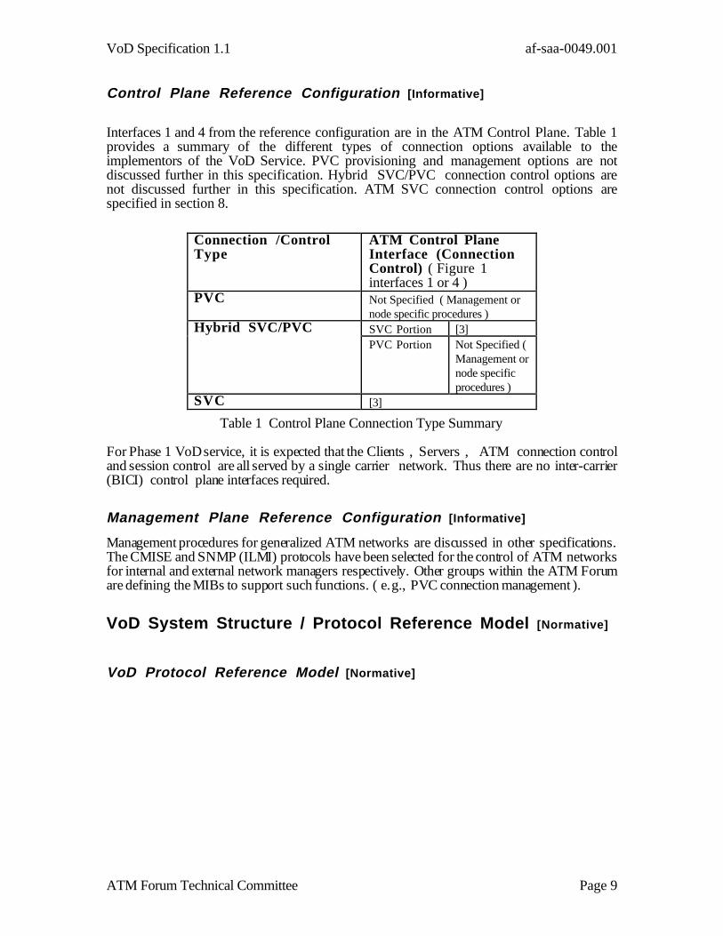
Interfaces 1 and 4 from the reference configuration are in the ATM Control Plane. Table 1provides a summary of the different types of connection options available to theimplementors of the VoD Service. PVC provisioning and management options are notdiscussed further in this specification. Hybrid SVC/PVC connection control options arenot discussed further in this specification. ATM SVC connection control options arespecified in section 8.
Table 1 Control Plane Connection Type Summary
For Phase 1 VoD service, it is expected that the Clients , Servers , ATM connection controland session control are all served by a single carrier network. Thus there are no inter-carrier(BICI) control plane interfaces required.
Management Plane Reference Configuration [Informative]
Management procedures for generalized ATM networks are discussed in other specifications.The CMISE and SNMP (ILMI) protocols have been selected for the control of ATM networksfor internal and external network managers respectively. Other groups within the ATM Forumare defining the MIBs to support such functions. ( e.g., PVC connection management ).
VoD System Structure / Protocol Reference Model [Normative]
VoD Protocol Reference Model [Normative]
Connection /ControlType
ATM Control PlaneInterface (ConnectionControl) ( Figure 1interfaces 1 or 4 )
PVC Not Specified ( Management ornode specific procedures )
Hybrid SVC/PVC SVC Portion [3]PVC Portion Not Specified (
Management ornode specificprocedures )
SVC [3]
VoD Specification 1.1 af-saa-0049.001
ATM Forum Technical Committee Page 10
AppropriateTransportProtocol
ConnectionControl
Audio Video PrivateData
Userto UserControl
Network Adaptation
AAL 5(I.363)
ATM
PHY
1
2
e.g.,H.262
e.g., MPEG
Transport StreamH.222.0 | ISO/IEC 13818-1
H.222.1ATMFSignaling 4.0Call Control
(Q.2931)
SSCF UNI(Q.2130)
SSCOP UNI(Q.2110)
SessionControl
e.g., DSM-CC U-U e.g., DSM-CC U-N or H.245
2
3 3 3 33
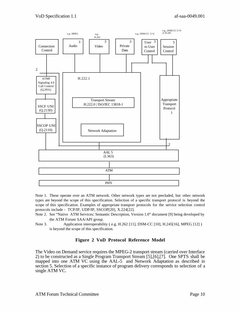
Note 1. These operate over an ATM network. Other network types are not precluded, but other networktypes are beyond the scope of this specification. Selection of a specific transport protocol is beyond thescope of this specification. Examples of appropriate transport protocols for the service selection controlprotocols include - TCP/IP, UDP/IP, SSCOP[20], X.224[22].Note 2. See “Native ATM Services: Semantic Description, Version 1.0” document [9] being developed by
the ATM Forum SAA/API group.Note 3. Application interoperability ( e.g. H.262 [11], DSM-CC [10], H.245[16], MPEG [12] )
is beyond the scope of this specification.
Figure 2 VoD Protocol Reference Model
The Video on Demand service requires the MPEG-2 transport stream (carried over Interface2) to be constructed as a Single Program Transport Stream [5],[6],[7]. One SPTS shall bemapped into one ATM VC using the AAL-5 and Network Adaptation as described insection 5. Selection of a specific instance of program delivery corresponds to selection of asingle ATM VC.

VoD Specification 1.1 af-saa-0049.001
ATM Forum Technical Committee Page 11
Figure 2 shows the VoD specification 1.0 protocol reference model. The ProtocolReference Model applies to all of the interfaces identified in Figure 1. Individual interfacesare not required to implement all of the options identified in the Protocol Reference Model.
ATM Control Plane Protocol Reference Model [Normative]
AppropriateTransportProtocol
ConnectionControl
Audio Video PrivateData
User toUser
Control
Network Adaptation
AAL 5(I.363)
ATM
PHY
e.g.,H.262
e.g., MPEG
Transport StreamH.222.0 | ISO/IEC 13818-1
H.222.1ATMFSignaling 4.0Call Control
(Q.2931)
SSCF UNI(Q.2130)
SSCOP UNI(Q.2110)
SessionControl
e.g., DSM-CC U-U e.g., DSM-CC U-N or H.245
Figure 3 Control Plane Protocol Reference Model
The Interfaces 1 and 4 of the Reference Configuration ( Figure 2 ) are control planeinterfaces. These interfaces shall support the shaded protocol stack shown in Figure 3including SSCOP [20], SSCF [21], Call Control [17] [3].
ATM User Plane Protocol Reference Model [Normative]
The Interfaces 2,3 and 5 of the Reference Configuration ( Figure 2 ) are ATM user planeinterfaces. These interfaces shall support the shaded protocol stacks shown in Figure 4 .

VoD Specification 1.1 af-saa-0049.001
ATM Forum Technical Committee Page 12
AppropriateTransportProtocol
ConnectionControl
Audio Video PrivateData
User toUser
Control
Network Adaptation
AAL 5(I.363)
ATM
PHY
e.g.,H.262
e.g., MPEG
Transport StreamH.222.0 | ISO/IEC 13818-1
H.222.1ATMFSignaling 4.0Call Control
(Q.2931)
SSCF UNI(Q.2130)
SSCOP UNI(Q.2110)
SessionControl
e.g., DSM-CC U-U e.g., DSM-CC U-N or H.245
1 2
Note 1. H.222.1 network adaptation is required for Interface 2. It is optional for Interface 3or 5.Note 2. An appropriate transport protocol is required for Interfaces 3 and 5. Thisspecification does not constrain the choice of an appropriate transport protocol. It is notrequired to be the same transport protocol used for interface 3 and interface 5. The transportprotocol is not required for Interface 2.
Figure 4 User Plane Protocol Reference Model
Client-Server Architecture [Informative]

VoD Specification 1.1 af-saa-0049.001
ATM Forum Technical Committee Page 13
Server
Client (e.g. STT/PC ) or IWU
ATMConnection
Control
Session
Control
ATM
ATM
AAL5
TS
Conn
Cont
H.222.1
TransStack
H.222.1
H.222.0
Network
Adaptation
ATM
AAL5
Video
ConnectionControl
Audio
Sig 4.0
sessioncontrol
TransStack
PrivateData
User-to-
UserControl
Sig 4.0
sessionlcontrol
Video
U-U control
UNI UNI
1 1
2
3 3
3 34
5
2
5
Note: In the case of an IWU terminating the ATM, the IWU does not necessarily terminate the MPEG-2 SPTS.The MPEG-2 SPTS may be transported to the end user on a different medium. Such interworkingarrangements and other media are beyond the scope of this specification.
Figure 5 VoD Protocol Reference Model applied to Reference Configuration
Figure 5 highlights the essential components of the Protocol Reference Model necessary fortransmitting stored video across an ATM network. The MPEG-2 data flows from a file systemthrough H.222.1 [6] across an ATM Virtual Circuit (using AAL5) to the target system whichmay be a client system or IWU.
The information (movies, commercials etc.) is stored in MPEG-2 Single Program TransportStream (SPTS) format. Since the video and audio information are already compressed andformatted as an MPEG-2 SPTS, no encoder or multiplexer is required to be present at theServer. The metadata associated with the MPEG-2 SPTS is implementation specific and willnot be specified in detail in this specification. This metadata may provide information such as:
• identification that the compressed data is CPR MPEG-2 SPTS Format• the MPEG-2 Bit Rate or Packet Rate• and any other necessary QoS information
The session control exchange between the Client or the Server and the Session Controller isperformed by an out-of-band data exchange (i.e., in a separate VC shown as interface 3 in the

VoD Specification 1.1 af-saa-0049.001
ATM Forum Technical Committee Page 14
reference configuration). This data exchange provides the ATM address and correlation ID(i.e., DSM-CC sessionId or H.245 resource/correlation number). The session control can beimplemented by mutual agreement between STT/PC vendors, session control vendors, andthe Server application vendors, e.g. using ISO/IEC DSM-CC 13818-6 [16] ( presently inCommittee Draft Status, scheduled to become Draft International standard in November 1995and International standard in March 1996).The information is used to establish interface 2 andinterface 5 connections between the Server and the Client. The circuit setup is initiated by theServer or Client.
Network Adaptation [Normative]
All equipment conformant with this specification shall support the following networkadaptation.
The MPEG-2 Single Program Transport Stream (SPTS) packets shall be mapped into theATM Adaptation Layer Type 5 (AAL5) with a NULL Service Specific ConvergenceSublayer.
In the mapping, one to N MPEG-2 Transport Streams (TS) packets are mapped into anAAL5-SDU.
For Switched Virtual Circuits (SVCs), the value of N is established via ATM Signaling 4.0at call setup using the AAL5 Maximum CPCS-SDU negotiation procedure. The AAL5Maximum CPCS-SDU size that is signaled is N*188 bytes (N being the number of TSpackets). This procedure is defined in the ATM Forum Signaling 4.0 specification. N usedto form the AAL5-SDUs shall be the Maximum CPCS-SDU Size / 188.
For Permanent Virtual Circuits (PVCs), the default value of N is two (Maximum CPCS-SDU size = 376 bytes). Other values of N may be selected by bilateral agreement betweenthe settop user and the server via network provisioning.
Furthermore, in order to insure a base level of interoperability, all equipment shall supportN = 2 (CPCS-SDU size = 376 bytes).
In summary, the mapping shall be:
1 Each AAL5-SDU shall contain (the negotiated) N MPEG-2 SPTS packets, unlessthere are fewer than N packets left in the SPTS. In the case when there are fewerthan N packets left in the SPTS, the final CPCS-SDU contains all of theremaining packets.
2 The value of N is established via ATM signaling using N = the AAL5CPCS-SDU size divided by 188. The default AAL5 CPCS-SDU size is 376octets, which is two TS packets (N = 2).
3 In order to ensure a base level of interoperability, all equipment shall support thevalue N=2 (AAL5 CPCS-SDU size of 376 octets).
Base level of N=2 [Normative]
When N=2, the Network Adaptation shall be as follows:
• ATM Adaptation Layer Type 5 (AAL5) with a NULL Service SpecificConvergence Sublayer shall be used.

VoD Specification 1.1 af-saa-0049.001
ATM Forum Technical Committee Page 15
• An AAL5 PDU shall contain two TS Packets unless it contains the last TS Packetof the SPTS.
• An AAL5 PDU shall contain one MPEG2 SPTS Packet if that MPEG-2 TSPacket is the last TS Packet of the SPTS.
When an AAL5 PDU contains two SPTS Packets, which have length 188 octets, the AAL5CPCS-SDU has length 376 octets. This AAL5 CPCS-SDU, together with the CPCS-PDUTrailer of 8 octets, requires 384 octets and maps into 8 ATM cells with zero CPCS paddingoctets. This is illustrated Figure 6.
CPCS-PDU payload (CPCS-SDU) CPCS-PDUTrailer
CPCS-PDU = 8 x 48 octets
MPEG-2 SPTSpacket i
MPEG-2 SPTSpacket i +1
376 octets 8 octets
188 octets 188 octets1st Octet ofMPEG SPTSpacket
Figure 6 Format of AAL-5 PDU Containing 2 TS Packets
AAL-5 Action on Corrupted PDUs [Normative]
When a receiver receives a corrupted AAL5 CPCS-PDU that has a correct length field,system performance may be improved by passing the corrupted data, together with anindication that it is corrupted, from the adaptation layer to the demultiplexer layer, ratherthan simply discarding the data in the adaptation layer. This is an end stationimplementation option [8].
Traffic Parameters [Normative]
Interfaces/ Connections Summary [Informative]
Interfaces 1 through 5 from Figure 1 may be mapped as separate VCs. The Interface 2 andInterface 5 information flows may be combined into one asymmetric VC.

VoD Specification 1.1 af-saa-0049.001
ATM Forum Technical Committee Page 16
Interface 1 is the VC reserved for normal SVC signaling operations at the UNI.Information concerning the traffic description of this VC is provided in [3].
Interface 2 is the VC(s) that will carry the principal information flow(s)(i.e. MPEG-2SPTS). The following sections provide further information on the traffic characteristics ofthis VC.
Interface 3 is an ATM User plane VC that carries Session Control information. The trafficdescription of this interface is implementation specific. In the absence of specificapplication information concerning Interface 3, implementors may wish to consider usingthe traffic description of other signaling VCs (e.g. that provided [3]).
Interface 4 is the VC(s) used for ATM Proxy Signaling connection control (as specified inthe [3]). Information concerning the traffic description of this VC is provided in [3]. Notethat additional bandwidth may be required to accommodate the signaling when the PSA actsfor many end points.
Interface 5 is one or more VC(s) for User to User control information. The trafficdescription of this interface is implementation specific. In the absence of specificapplication information concerning Interface 5, implementors may wish to consider usingthe traffic description of other signaling VCs (e.g. that provided [3]).
ATM Layer Traffic Description [Normative]
The following sections provide information on the traffic description for Interface 2connections.
Relationship between the MPEG-2 SPTS rate and ATM cell rate [Informative]
The source MPEG-2 SPTS is considered a CPR stream of information. After networkadaptation, the resulting cell stream shall use the ATM layer traffic descriptor of CBR.
Consider a MPEG-2 SPTS with a Transport Stream rate of M packets per second.
Using the default mapping exclusively then -
ATM layer Peak Cell Rate = 4*M cells per second.
ATM Layer Traffic Shaping [Normative]
Traffic at the egress of the server shall be shaped to conform to the CBR traffic contractnegotiated with the ATM network. Note that traffic shaping is required to occur on a perVC basis by [19] and [4].
ATM Layer Traffic Contract Parameter - CDVtolerance [Normative]
In the traffic contract, some jitter of the cell interval from the theoretical arrival timederived from the Peak Cell Rate is permitted. Annex A provides some discussion ofpotential sources of jitter for this application. The Generic Cell Rate Algorithm (GCRA)provides a constraint on the amount of such jitter where the network performs policingfunctions (i.e. UPC and NPC functions). The maximum allowable jitter is specified in theCDVtolerance parameter of the UPC/NPC function in the network.
VoD Specification 1.1 af-saa-0049.001
ATM Forum Technical Committee Page 17
Server implementations may introduce some CDV on the cell stream (e.g. due to cellmultiplexing of multiple VCs onto a single physical UNI. The network operator shallspecify the CDVtolerance parameter value (s) that apply to the VCs at the server interface. TheVCs from the server shall comply with the negotiated traffic contract or else the networkmay discard cells in accordance with the GCRA policing mechanism identified in [4].
Server implementors should note that the value of the CDVtolerance parameter specified by thenetwork operator includes delay variation (jitter) terms due to ATM layer operations andalso PHY layer operations. Refer to Annex A for further information on jitter terms. Referto Annex D for further information on the traffic description and selecting values of theCDVtolerance parameter.
Quality of Service Parameters [Normative]
ATM Layer QoS Parameters [Normative]
Delay Parameters [Normative]
There are two delay parameters to be specified:
• peak-to-peak-CDV• maximum CTD
These parameters are defined in [4] as negotiated parameters for the CBR service category.The peak-to-peak CDV parameter provides information on the delay variation (jitter) ofATM cells as seen by the receiving end of an ATM connection. Set Top Terminalimplementors are cautioned that jitter terms due to processing above the ATM layer ( e.g.,due to Network Adaptation processes ) may also apply. Refer to Annex A for additionalinformation on jitter terms.
The peak-to-peak CDV parameter should not be confused with the CDVtolerance parameterassociated with the per VC UPC functions of the ATM network. The CDVtolerance parameteris not a negotiated parameter. Annex D provides additional information on selection ofspecific values of the CDVtolerance parameter.
Accuracy and dependability parameters [Normative]
There are three accuracy and dependability parameters to be specified :
• Cell Loss Ratio (CLR)• Cell Error Ratio (CER)• Severely Errored Cell Block Ratio (SECBR)
Annex C shows the relationships of the two accuracy and dependability parameters(ECBR, MECBC) to these ATM layer parameters. These parameters are defined inAppendix A of [1],[2] and [4]. In [4], CLR is a negotiated parameter . CER and SECBRare not negotiated parameters and their values are specified by service contracts or othermeans. CLR may be indicated as a QoS class or as a QoS parameter.
VoD Specification 1.1 af-saa-0049.001
ATM Forum Technical Committee Page 18
Connection Control [Normative]
Between the VoD Server and the VoD Client (or IWU), VC(s) shall be established for theU-U control and video (interfaces 2 and 5 of the reference diagram). These can be eitherPVC(s) or SVC(s).
SVCs are established through the ATM network by control plane signaling. The controlplane signaling uses [3].
PVCs are established through the ATM network by management plane procedures . Theseprocedures are out of the scope of this specification.
Network Assumption [Normative]
For Phase 1 VoD, it is expected that the clients , servers and ATM connection control andsession control are all served by a single carrier network. Thus there are no inter-carrier(BICI) interfaces required.
SVC(s) Connection Setup Capabilities [Normative]
SVC(s) shall be established based on one of the following approaches in compliance with [3]:
• call/control without PSA assistance ( also called : first party)• proxy signaling• combinations of the above
An out-of-Band service selection and control (session management) protocol such asISO/IEC MPEG-2 DSM-CC User-to-Network messages or H.245 shall be used. Suchprotocols exchange messages through the user plane of ATM and AAL-5. This specificationprovides the ATM connection control functions which DSM-CC User-to-Network messagesrequire for its session management in the ATM network. If DSM-CC is used, then sessioncontrol may be used to obtain the necessary information for connection establishment.
VoD Specification 1.1 af-saa-0049.001
ATM Forum Technical Committee Page 19
First Party Connection Reference Model [Informative]
Server Client (e.g. STT/PCor IWU
Video
Session
Control
ATM
U-U control
UN I UNI
1 1
2
3 3
3 3
5
2
5
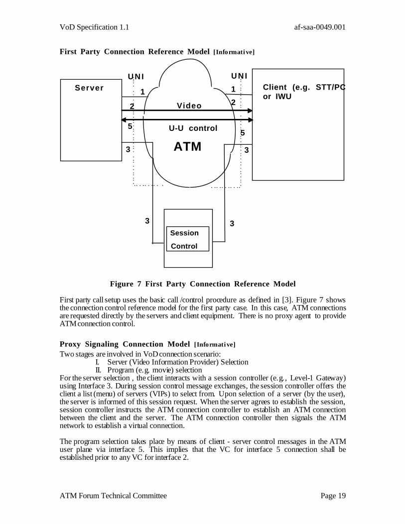
Figure 7 First Party Connection Reference Model
First party call setup uses the basic call /control procedure as defined in [3]. Figure 7 showsthe connection control reference model for the first party case. In this case, ATM connectionsare requested directly by the servers and client equipment. There is no proxy agent to provideATM connection control.
Proxy Signaling Connection Model [Informative]
Two stages are involved in VoD connection scenario:I. Server (Video Information Provider) SelectionII. Program (e.g. movie) selection
For the server selection , the client interacts with a session controller (e.g., Level-1 Gateway)using Interface 3. During session control message exchanges, the session controller offers theclient a list (menu) of servers (VIPs) to select from. Upon selection of a server (by the user),the server is informed of this session request. When the server agrees to establish the session,session controller instructs the ATM connection controller to establish an ATM connectionbetween the client and the server. The ATM connection controller then signals the ATMnetwork to establish a virtual connection.
The program selection takes place by means of client - server control messages in the ATMuser plane via interface 5. This implies that the VC for interface 5 connection shall beestablished prior to any VC for interface 2.

VoD Specification 1.1 af-saa-0049.001
ATM Forum Technical Committee Page 20
The signaling interface between the ATM connection controller and the ATM network is [3]. Itshould be noted that the ATM connection controller will act on behalf of the client and /or theserver to establish ATM connections between these two parties.
The interface between both the client and the server to the network is a UNI without signalingcapability. PVCs are assumed to be provisioned between the end-user and the sessioncontroller, and between the server and the session controller to carry session control messagesfor establishment of a session between the client and the server.
Implementations of the ATM Connection Control function may be distributed across severalnetwork elements. This may be appropriate for ease of administration and/or to allow forsignificant differences in the network segments. Decisions on when to distribute ATMconnection control functions are implementation specific. In the case of a distributedimplementation of the ATM connection control function, the individual instances shall act asindependent PSAs or collections of independent PSAs. Each PSA shall act in compliance with[3]. Refer to Annex E for further information on PSAs. In addition to the details provided in[3], additional study is required to determine the proper protocol and procedures to allowUNIs controlled by failed PSAs or signaling links to continue to be controlled during suchoutages.
The general proxy signaling model can be refined into some simpler scenarios:• neither Server nor Client support signaling• Server supports signaling, but Client does not.• Client supports signaling, but Server does not
The case where a client or server has the capability for signaling, but chooses not tosupport it for specific operations, is implementation specific.

VoD Specification 1.1 af-saa-0049.001
ATM Forum Technical Committee Page 21
ServerClient(eg. STT/PC)or IWU
Video
ATM
ConnectionControl
Session
Control
ATMU-U control
UN I UNI
UNI in SVC case
2
3 3
3 3
4
5
2
5
Figure 8 proxy signaling when neither Server nor Client support signaling
Figure 8 shows the proxy signaling reference model in the case when neither Server norClient support signaling. In this case there is no interface 1 between the Server or Clientand the network.

VoD Specification 1.1 af-saa-0049.001
ATM Forum Technical Committee Page 22
Proxy Signaling when Server supports signaling, but Client does not[Informative]
ServerClient (e.g. STT/PC)or IWU
Video
ATMConnection
Control
Session
Control
ATMU-U control
UN I UNI
UNI in SVC case
1
2
3 3
3 3
4
5
2
5
Figure 9 Proxy Signaling when Server supports signaling, but the clientdoes not
Figure 9 shows the proxy signaling reference model in the case when Server supportssignaling, but the Client does not. In this case there is no interface 1 between the Client andthe network.
VoD Specification 1.1 af-saa-0049.001
ATM Forum Technical Committee Page 23
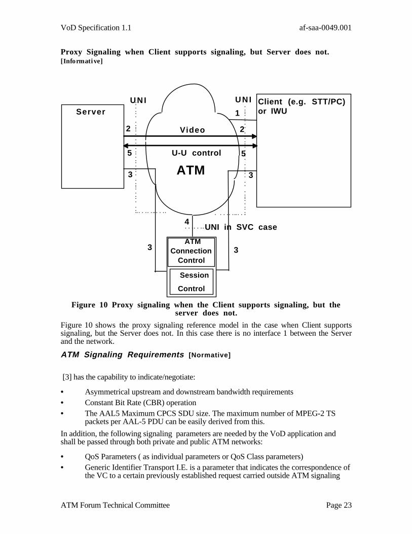
Proxy Signaling when Client supports signaling, but Server does not.[Informative]
ServerClient (e.g. STT/PC)or IWU
Video
ATMConnection
Control
Session
Control
ATMU-U control
UN I UNI
UNI in SVC case
1
2
3 3
3 3
4
5
2
5
Figure 10 Proxy signaling when the Client supports signaling, but theserver does not.
Figure 10 shows the proxy signaling reference model in the case when Client supportssignaling, but the Server does not. In this case there is no interface 1 between the Serverand the network.
ATM Signaling Requirements [Normative]
[3] has the capability to indicate/negotiate:
• Asymmetrical upstream and downstream bandwidth requirements• Constant Bit Rate (CBR) operation• The AAL5 Maximum CPCS SDU size. The maximum number of MPEG-2 TS
packets per AAL-5 PDU can be easily derived from this.
In addition, the following signaling parameters are needed by the VoD application andshall be passed through both private and public ATM networks:
• QoS Parameters ( as individual parameters or QoS Class parameters)• Generic Identifier Transport I.E. is a parameter that indicates the correspondence of
the VC to a certain previously established request carried outside ATM signaling

VoD Specification 1.1 af-saa-0049.001
ATM Forum Technical Committee Page 24
Interfaces / Connections [Informative]
Interfaces 1 through 5 from Figure 1 may be mapped as separate VCs. One Interface 2connection and one Interface 5 connection may be established as a single asymmetric VC.
Interface 1 is the VC reserved for normal SVC signaling operations at the UNI. Theinformation elements required to establish or release other VCs required for the service(e.g., Interface 2, 5) shall be sent over this interface according to the procedures of [3].This signaling VC is provisioned at subscription time for the Client or Server.
Interface 2 is the VC that will carry the User-to-User information (i.e. MPEG-2 SPTS).The following sections provide further information on the information elements required toestablish this VC. This VC is established last.
Interface 3 is an ATM User plane VC that carries Session Control information. This VCmay be established by PVC or SVC operations. If SVC operations are used to establish theVC, the information elements and procedures of [3] be used. This VC is established priorto any VCs corresponding in Interface 2 or 5.
Interface 4 is the VC(s) used for Proxy Signaling (i.e., ATM connection control). Thisshall be identified as a signaling VC on the UNI between the ATM network and thenetwork element performing the ATM Connection Control function. The informationelements required to establish or release other VCs required for the service (e.g., Interface2, 5) shall be sent over this interface according to the procedures of [3]. Note thatadditional provisioning information is required in the ATM network for interface 4(compared to Interface 1). Refer to Annex E for further information. This signaling VC isprovisioned when the PSA/ATM Connection controller is deployed. The PSA must be re-provisioned to accommodate changes in the Clients and Servers that are served by the PSA.Some Implementations of Interface 4 may carry the signaling for many end points. Inorder to increase the reliability of the VoD service delivery , implementors may wish toimplement some form of redundancy at this interface. Interface 4 redundancy may beimplemented at the physical layer ( e.g. SONET 1+1 Automatic Protection Switching) or ata higher layer. Selection of a particular redundancy scheme is beyond the scope of thisspecification.
Interface 5 is one or more VC(s) for User to User control information. When required bythe service, Interface 5 should be established using the same control technique (SVC orPVC) as the Interface 2 VC. When SVC operations are used to establish VCs for Interface5, the information elements and procedures from [3] shall be used. This VC shall beestablished prior to any VC corresponding to Interface 2. The Generic Identifier TransportIE used in establishing the Interface 5 connection should be consistent with the associatedInterface 2 connection(s).
ATM Signaling Information Elements Required [Normative]
The following Information Elements are required in the SETUP Message to establishcommunications for Interface 2.

VoD Specification 1.1 af-saa-0049.001
ATM Forum Technical Committee Page 25
Requiredfor VoD
Information Element Notes
X Protocol discriminator
X Call Reference
X Message type
X Message length
X AAL Parameters
X ATM Traffic descriptor
X Broadband bearer capability
X Broadband repeat indicator
O Broadband low layer information
X Generic Identifier Transport
X Broadband Higher layer information
O Notification Indicator
X Called party number
X Called party subaddress
O Calling party number
O Calling party subaddress
OP Connection identifier
O QoS parameter
O End-to-end transit delay
O Extended QOS Parameters
C Broadband sending complete
NA Transit network selection User-->Networknetwork assumption : does notcross BICI
NA Endpoint reference IE used for multipoint operationwhich is beyond scope of thisspecification
NA - Not Applicable for the VoD ServiceX - Required for the VoD ServiceO - Optional for the VoD ServiceC - Conditional ( if appropriate for the network being used) for the VoD ServiceOP - Optional (if Proxy Signaling is used see Signaling 4.0 for proper setting)
Figure 11 ATM Forum Signaling 4.0 Information Elements
The Figure 11 identifies the information Elements (IEs) that are carried by the messages of[3]. All Information Elements may be sent in both directions ( U-N and N-U) unlessotherwise specified.
ATM Signaling Information Elements Coding Requirements [Normative]
The IE’s shall be set in accordance with [3]. The following are guidelines for setting ofselected parameters in the various IE’s required for the establishment of the PrincipalInformation Flow ( i.e. across Interface 2) for the VoD service.

VoD Specification 1.1 af-saa-0049.001
ATM Forum Technical Committee Page 26
AAL Parameters I.E. [Normative]
Information Element Value Notes
AAL type AAL-5.
Forward Maximum AAL-5CPCS SDU size
N*188 bytes. Default value for the videoservice component in thisspecification is 376 bytes.N is an integer.
Backward Maximum AAL-5 CPCS-SDU size
0 bytes if Video ServiceComponent isunidirectional, otherwiseImplementation Specific
SSCS Type Null
ATM Traffic Descriptor I.E. [Normative]
The video service component Peak Cell Rate is calculated with MPEG-2 encoded rate plusAAL5 overhead. Refer to section 6.2.1 for further information on calculating the Peak CellRate. The ATM Traffic Descriptor includes only the user plane information rate for theservice components in that one VC.
The video service component PCR may be specified using CLP =0 and / or CLP=0+1.Video service component specific use of CLP=1 marking is for further study.
Information Element Value Notes
Forward Peak Cell Rate implementation andprogram selection specific
Set to the Peak Cell Ratevalue required for the videoservice component (MPEG-2 SPTS)
Backward Peak Cell Rate 0 cells/ sec if Video ServiceComponent isunidirectional, otherwiseImplementation Specific
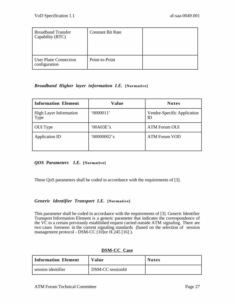
Broadband bearer capabilities I.E. [Normative]
Information Element Value Notes
Bearer Class BCOB-X
VoD Specification 1.1 af-saa-0049.001
ATM Forum Technical Committee Page 27
Broadband TransferCapability (BTC)
Constant Bit Rate
User Plane Connectionconfiguration
Point-to-Point
Broadband Higher layer information I.E. [Normative]
Information Element Value Notes
High Layer InformationType
‘0000011’ Vendor-Specific ApplicationID
OUI Type ‘00A03E’x ATM Forum OUI
Application ID ‘00000002’x ATM Forum VOD
QOS Parameters I.E. [Normative]
These QoS parameters shall be coded in accordance with the requirements of [3].
Generic Identifier Transport I.E. [Normative]
This parameter shall be coded in accordance with the requirements of [3]. Generic IdentifierTransport Information Element is a generic parameter that indicates the correspondence ofthe VC to a certain previously established request carried outside ATM signaling. There aretwo cases foreseen in the current signaling standards (based on the selection of sessionmanagement protocol - DSM-CC [10]or H.245 [16] ).
DSM-CC Case
Information Element Value Notes
session identifier DSM-CC sessionId

VoD Specification 1.1 af-saa-0049.001
ATM Forum Technical Committee Page 28
resource correlation number DSM-CC resourceNum
H.245 Case
Information Element Value Notes
Session/Resource Identifier for the virtualcircuit
H.245 resource/correlationnumber
Other Information Elements [Normative]
The remaining Information Elements shall be coded in accordance with the requirements of[3].
Note that some of the Information Elements require the use of valid ATM network endpointaddresses. Valid ATM network endpoint addresses are defined in [3]. These addressformats include native E.164 and the Designated Country Code (DCC), International CodeDesignator (ICD) and E.164 [13] versions of the ATM End System Address (AESA)address format.
Session Control [Informative]
Session control procedures depend on the network to manipulate the ATM networkresources, that will be used in the communications between the servers and clients.Examples of session control protocols include:
• ISO/IEC MPEG-2 DSM-CC [10]
• H.245[16]
Specification of specific session control procedures is beyond the scope of thisspecification.

VoD Specification 1.1 af-saa-0049.001
ATM Forum Technical Committee Page 29
VoD Specification 1.1 af-saa-0049.001
ATM Forum Technical Committee Page A-1
End To End Jitter [Informative ]
Introduction
Transporting time critical information streams using higher protocol layers requires theexchange of timing information between the protocol layers. The layer adaptation processesbetween protocol layers transform the jitter of one layer into the jitter of another layer. Withineach layer, there are processes (e.g., switching) that introduce additional jitter terms. Acomprehensive framework is needed to assemble all these different jitter terms.
A simple end-to-end model of the transport connection for a time critical information stream isintroduced using the standard trail and connection nomenclature from G.803 i. This modelthen serves as the basis for identification and discussion of several different jitter phenomena.In particular, this layering approach separates the cumulative jittering effects that occur withineach layer from the transformational jitter effects of layer adaptation. To aid the properaccumulation and transformation of the jitter, it is helpful to keep all jitter measures to the sameaccuracy (e.g., Probability [peak-to-peak jitter exceeding value] < 10-10).
For real network services based on ATM connections, there may be many different jittereffects present. This is not intended to be a comprehensive analysis of all jitter components forall types of services. Examples of the jitter terms associated with the transport of an MPEG-2Single Program Transport Stream are described.
End to End Connection Model
An MPEG-2 Single Program Transport Stream is encapsulated in an AAL-5 PDU and thentransmitted as ATM cells over a SONET transport network from a source equipment to a sinkequipment. A diagram can be drawn using the G.803 notation to show the adaptationfunctions that are required to transform the characteristic information of one trail layer intoanother. The various sources of jitter can be associated with either the layer adaptationfunctions or the connection termination functions. The relative importance of these sources ofjitter may be different in each layer. The VC-4 layer and ATM VC layer are identified inG.803.
Jitter is dimensioned in units of time. More specifically, jitter terms describe a time deviationfrom some expected significant instant for a specific s ignal type . Each layer of the G.803model represents a different specific signal type. This signal type is referred to as the‘characteristic information’ that is transported by that layer. Jitter should be expressed in termsthat are relative to the characteristic information of the layer concerned (e.g., Cell DelayVariation for the ATM VC layer, PDU Delay Variation (PDV) for AAL-5 PDUs, etc.).
Layer Synchronization
In order to understand the propagation of jitter through these networks, it is important tounderstand the timing configurations possible. The public networks typically provide asynchronization source that is traceable to national standards. In some applications, thesource equipment may generate its own timing. The different layers can be operated withindependent synchronization. There may be advantages for this in particular deploymentscenarios. If two layers have different independent timing, the layer adaptation processes mustaccommodate this by including, for example, a rate adaptation process.
VoD Specification 1.1 af-saa-0049.001
ATM Forum Technical Committee Page A-2
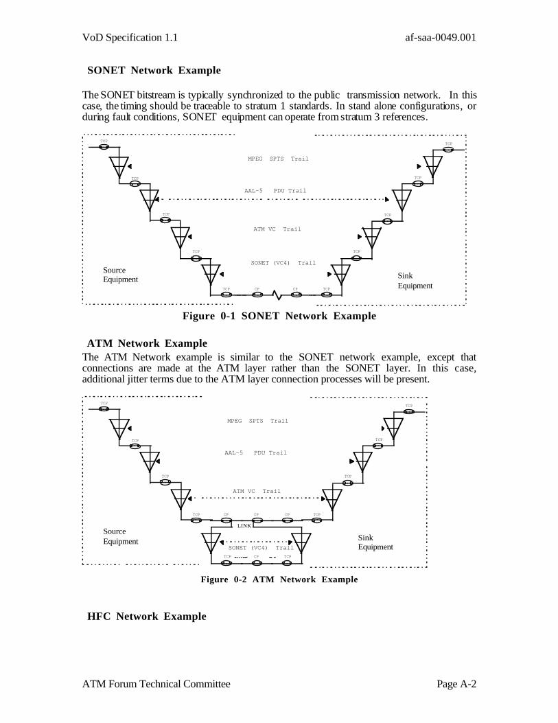
SONET Network Example
The SONET bitstream is typically synchronized to the public transmission network. In thiscase, the timing should be traceable to stratum 1 standards. In stand alone configurations, orduring fault conditions, SONET equipment can operate from stratum 3 references.
MPEG SPTS Trail
TCP
TCP
TCP
TCP
AAL-5 PDU Trail
ATM VC Trail
SONET (VC4) Trail
TCP CP TCP
TCP
TCP
TCP
TCP
SinkEquipment
SourceEquipment
CP
Figure 0-1 SONET Network Example
ATM Network ExampleThe ATM Network example is similar to the SONET network example, except thatconnections are made at the ATM layer rather than the SONET layer. In this case,additional jitter terms due to the ATM layer connection processes will be present.
MPEG SPTS Trail
TCP
TCP
TCP
TCP
AAL-5 PDU Trail
ATM VC Trail
SONET (VC4) Trail
TCP
CP
TCP
TCP
TCP
TCP
TCP
SinkEquipment
SourceEquipment
CP
CPCP
LINK
Figure 0-2 ATM Network Example
HFC Network Example

VoD Specification 1.1 af-saa-0049.001
ATM Forum Technical Committee Page A-3
The HFC Network example is similar to the ATM network example, in that connectionsare made at the ATM layer rather than the SONET layer. In addition, the MPEG TS packetsare remapped into a new modulation scheme for transport over the HFC cable plant. In thiscase, additional jitter terms due to the remapping between the ATM transport and the HFCtransport processes, as well as jitter introduced by the HFC modulation scheme will bepresent. The jitter terms present in a particular deployment are highly implementationdependent and may be affected by many aspects, e.g. buffering, remapping of MPEG-2PCRs etc as well as the network topology.
MPEG SPTS Trail
TCP
AAL-5 PDU Trail
ATM VC Trail
Sink Equipment
SourceEquipment
CP
TCP
TCP
TCP
TCP
TCP
TCP
TCPCP
CPCP CP CP CP CP
CPCP
TCP
TCP
TCPTCP
TCP
HFC Trail
ATM/HFCInterworkingEquipment
HFC Network
Figure 0-3 HFC Network Example
Layer Adaptation Processes
Generic Processes
Rate Adaptation
Cell Cell CellCell Cell Cell Cell CellCell Cell Cell
Cell Cell Cell Cell Cell Cell Cell Cell Cell Cell
Input Cell Streame.g. Single VC
Output Cell StreamInserted cellfor Rate Adaptation
Figure 0-4 Rate Adaptation Example
VoD Specification 1.1 af-saa-0049.001
ATM Forum Technical Committee Page A-4
Rate adaptation, or rate decoupling, occurs when the characteristic information rates of twolayers are different. When this occurs, additional “stuffing” information is inserted in order tomaintain the transmission rate of the higher bit rate stream. Rate decoupling is a layeradaptation process. It could be used between any two layers with independent timing.Figure 0-4 shows an example where an ATM cell stream (e.g. a single VC) is rate adaptedinto a higher rate cell stream. In this case, the stuffing is quantized to one cell period.
Cell rate decoupling in the ATM Forum UNI 3.0 specificationii refers to an ATM layer processwhere the sending process inserts “unassigned” cells as necessary to form a contiguous cellstream. ITU-T uses the term to refer to a PHY layer process that involves the insertion of“idle” cells. Both processes result in a displacement of a source traffic cell by one or more cellperiods .
Multiplexing
Consider the cell stream comprising one VC that is to be mixed into a composite cell streamwith other cells. The CDV of a VC is affected by the other traffic in the composite ATM cellstream. The ATM cell stream contains cells from many VCs as well as overhead cells such asOA&M cells and rate adaptation cells (“idle” or ”unassigned”).
The CDV of a VC cell stream is quantized with a granularity of the cell period of the compositeATM cell stream. The jitter functions associated with cell switching or multiplexing mayresult in CDV quantization steps greater than one cell. The maximum CDV quantization step isrelated to the burst size that can exist in cells extraneous to the VC. The burst lengths tend toincrease as the utilization of a composite ATM cell stream increases. Hence the CDV can beexpected to be related to the utilization of a particular ATM connection.
The existence of correlating traffic patterns between different VCs may also complicate theanalysis. Multiple VCs with the same nominal CBR rate may produce repetitive effects overmultiple cell periods. VBR traffic is more likely to be non stationary in nature.
Traffic Shaping
Traffic shaping can be applied in various ways. One could introduce traffic shaping at theAAL-5 level , or at the MPEG-2 level. One could argue that a CPR MPEG-2 SPTS hasalready been shaped (to a constant packet rate). The most common use of the term isassociated with shaping of traffic on a single connection by end user equipment (e.g.,CPE) in order to comply with the traffic contract agreed between the user and the networkoperator.
ATM Traffic shaping is applicable to all Broadband Transfer Capability types except UBR.In the case of a VC with a traffic contract specifying a CBR traffic descriptor, end userequipment may be required to provide buffering and scheduling functions at the source inorder to ensure that cells of that VC comply with the cell spacing requirements expected ofa CBR cell stream. Delay variations in these buffering and scheduling functions of the enduser equipment may result in additional jitter terms.
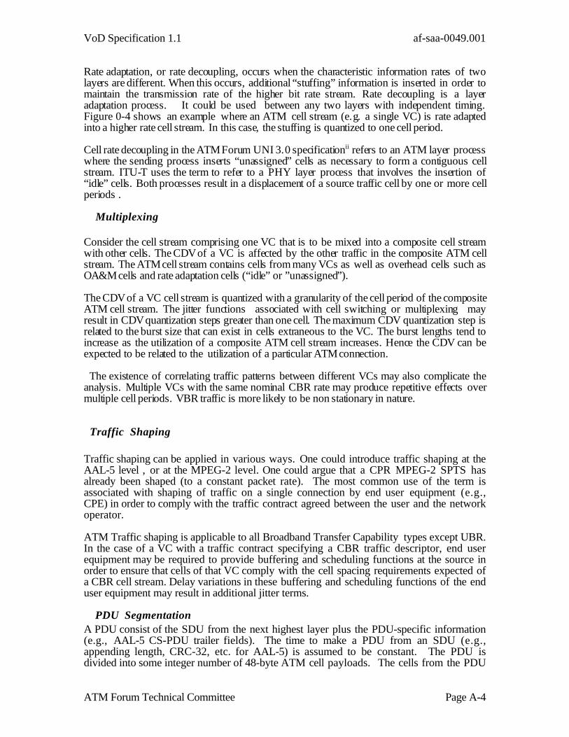
PDU SegmentationA PDU consist of the SDU from the next highest layer plus the PDU-specific information(e.g., AAL-5 CS-PDU trailer fields). The time to make a PDU from an SDU (e.g.,appending length, CRC-32, etc. for AAL-5) is assumed to be constant. The PDU isdivided into some integer number of 48-byte ATM cell payloads. The cells from the PDU

VoD Specification 1.1 af-saa-0049.001
ATM Forum Technical Committee Page A-5
are associated with a VCC, and are multiplexed onto the ATM link as described in sectionA-3.1.2 above. The cells from the PDU may be metered out in any burst size up to thePDU size, at a rate proportional to the PDU rate such that the process receiving the PDUshould neither overflow or underflow its PDU buffer. i.e.,
cell rate = PDU rate * PDU size (cells) / burst size (cells)
The delay to segment a PDU is constant, and depends on the time to transfer the individualcells:
PDU segmentation delay = 1 / cell rate
PDU Re-Assembly
The process of reassembly of cells into a PDU takes an interval of time that is assumed to beequal to the time to accumulate the necessary number of cells. The time to extract the PDUfrom the accumulated cells is assumed to be constant and negligible in magnitude comparedwith one cell period. The cell arrival times are assumed to be jittered by some probabilisticCDV function. Figure 0-5 shows the basic model of cell arrival and PDU re-assembly. Thenominal PDU interval (in this example) is 8 times the nominal cell interval. The actual PDUinterval value adds the CDV values from the last cell of the current PDU and the previousPDU.
The cumulative distribution of the PDV could be considered as a sample distribution drawnfrom the cumulative CDV population. The central limit theorem would suggest that sampleswould tend toward the mean rather than extremes. Since this is essentially an infinitepopulation, and the sample size is also infinite, the effect due to such sampling is likely to besmall. A worst case assumption is that a peak to peak CDV of less than x mS with aconfidence of 10-10 implies a peak to peak AAL-5 PDV of less than x mS with a confidence of10-10.
AAL-5 PDUAAL-5 PDU AAL-5 PDU Interarrival Time
CellCell Cell Cell Cell Cell Cell Cell Cell
Cell Interarrival Time
CellCellCellCell
Actual PDU Interval
Nominal PDU Interval
CDV of Cell # 8from PDU #1
CDV of Cell # 8from PDU #0
PDV of PDU #1 PDV of PDU #0
Figure 0-5: CBR Model for CDV
VoD Specification 1.1 af-saa-0049.001
ATM Forum Technical Committee Page A-6
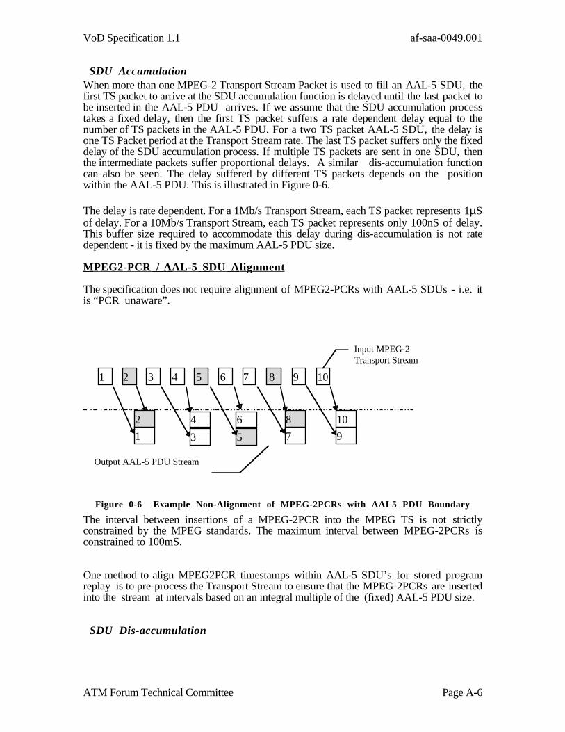
SDU AccumulationWhen more than one MPEG-2 Transport Stream Packet is used to fill an AAL-5 SDU, thefirst TS packet to arrive at the SDU accumulation function is delayed until the last packet tobe inserted in the AAL-5 PDU arrives. If we assume that the SDU accumulation processtakes a fixed delay, then the first TS packet suffers a rate dependent delay equal to thenumber of TS packets in the AAL-5 PDU. For a two TS packet AAL-5 SDU, the delay isone TS Packet period at the Transport Stream rate. The last TS packet suffers only the fixeddelay of the SDU accumulation process. If multiple TS packets are sent in one SDU, thenthe intermediate packets suffer proportional delays. A similar dis-accumulation functioncan also be seen. The delay suffered by different TS packets depends on the positionwithin the AAL-5 PDU. This is illustrated in Figure 0-6.
The delay is rate dependent. For a 1Mb/s Transport Stream, each TS packet represents 1µSof delay. For a 10Mb/s Transport Stream, each TS packet represents only 100nS of delay.This buffer size required to accommodate this delay during dis-accumulation is not ratedependent - it is fixed by the maximum AAL-5 PDU size.
MPEG2-PCR / AAL-5 SDU Alignment
The specification does not require alignment of MPEG2-PCRs with AAL-5 SDUs - i.e. itis “PCR unaware”.
9
10
5
6 8
7
2
1
4
3
1 2 3 4 5 6 7 8 9 10
Input MPEG-2Transport Stream
Output AAL-5 PDU Stream
Figure 0-6 Example Non-Alignment of MPEG-2PCRs with AAL5 PDU Boundary
The interval between insertions of a MPEG-2PCR into the MPEG TS is not strictlyconstrained by the MPEG standards. The maximum interval between MPEG-2PCRs isconstrained to 100mS.
One method to align MPEG2PCR timestamps within AAL-5 SDU’s for stored programreplay is to pre-process the Transport Stream to ensure that the MPEG-2PCRs are insertedinto the stream at intervals based on an integral multiple of the (fixed) AAL-5 PDU size.
SDU Dis-accumulation

VoD Specification 1.1 af-saa-0049.001
ATM Forum Technical Committee Page A-7
The AAL-5 PDU structure provides for multiple MPEG SPTS packets to be multiplexedinto one AAL-5 SDU. When dis-accumulating this SDU, these SPTS packets becomeavailable at the same time. This burstiness may create problems for the next (higher) layer.While the segmentation and reassembly function can be expected to preserve the order ofthe packets, this SDU dis-accumulation operation represents a severe jitter as shown inFigure 0-7. Successive MPEG SPTS packets would be sent resulting in successive inter-arrival intervals of zero and twice the nominal interarrival rate. If a buffer of the MPEGSPTS packets is required, then the control of the buffers could become complex. Sendingthe TS packets as soon as they become available treats MPEG SPTS packets uniformly.
The jitter term varies according to the bandwidth assumption. For a nominal CBRMPEG bit rate, the jitter term is one MPEG SPTS packet period.
TS PKT TS PKT
AAL-5 PDUAAL-5 PDUAAL-5 PDU Interarrival Time
CellCell Cell Cell Cell Cell Cell Cell Cell
Cell Interarrival Time
CellCellCellCell
TS PKT TS PKT
TS Packet Interarrival Time
Adjacent TS Packets with Interarrival Time = essentially zero
Figure 0-7 Demultiplexed TS Packets
Specific Layer AdaptationsSpecific layer adaptation functions apply between specific layers.
ATM Cell Stream to/from SONET
SONET layer jitter effects can be caused by normal equipment tolerances and environmentalvariations. Physical layer jitter effects associated with the recovery of the bit level timing iswell documented by T1X1 and others. There are some systematic jitter effects associatedwith the frame structure of the SONET frame but these are regular in nature.
For example, one of the largest SONET jitter terms is associated with the systematic jitterintroduced by the SONET frame header. At OC-3c rates, the jitter magnitude is 9 octetsrepresenting one row of header information. 9 octets is less than the cell period of 53 octets.SONET systematic jitter terms are typically eliminated by the pointer manipulation buffersassociated with layer adaptation function of the SONET trail termination equipment. Some
VoD Specification 1.1 af-saa-0049.001
ATM Forum Technical Committee Page A-8
equipments may provide a burst interface to the higher layer. For the purposes of thiscontribution, we assume that the payload provided from the SONET layer to the ATM Layeris a contiguous payload bitstream.
The ATM layer may operate in a manner synchronized to the incoming SONET payloadstream. Some equipments may terminate multiple SONET payload streams. Rate adaptationof the incoming SONET payload stream to an internal time reference is a typical layeradaptation process to accommodate this. If the incoming SONET payload stream is notjittered, the rate adaptation process would introduce a systematic jitter based on the ratedifference. Jitter in the timing of the SONET payload stream would be manifest at the ATMlayer as randomization of the insertion point of the rate decoupling cells.
The jitter transformation of this layer adaptation process is not linear. A jitter quantizationeffects occurs. Consider a contiguous ATM cell stream recovered from a SONET layer. Thelocal timing of the cell intervals is fixed. Jitter at the cell level must occur in discrete intervalsequal to the cell period. Hence small jitter effects from the SONET layer can be aggregatedinto a probabilistic jitter function with a magnitude of 1 cell period. At OC-3c rates, one cellperiod is approximately 3µS.
AAL-5 PDU stream to/from ATM
AAL-5 PDUAAL-5 PDU AAL-5 PDU Interarrival Time
CellCell Cell Cell Cell Cell Cell Cell Cell
Cell Interarrival Time
CellCellCellCell
Actual PDU Interval
Nominal PDU Interval
CDV of Cell # 8from PDU #1
CDV of Cell # 8from PDU #0
PDV of PDU #1 PDV of PDU #0
Figure 0-8 AAL-5 PDU Stream to/from ATM
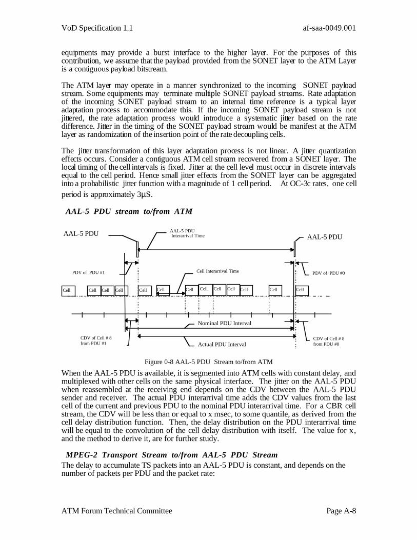
When the AAL-5 PDU is available, it is segmented into ATM cells with constant delay, andmultiplexed with other cells on the same physical interface. The jitter on the AAL-5 PDUwhen reassembled at the receiving end depends on the CDV between the AAL-5 PDUsender and receiver. The actual PDU interarrival time adds the CDV values from the lastcell of the current and previous PDU to the nominal PDU interarrival time. For a CBR cellstream, the CDV will be less than or equal to x msec, to some quantile, as derived from thecell delay distribution function. Then, the delay distribution on the PDU interarrival timewill be equal to the convolution of the cell delay distribution with itself. The value for x,and the method to derive it, are for further study.
MPEG-2 Transport Stream to/from AAL-5 PDU StreamThe delay to accumulate TS packets into an AAL-5 PDU is constant, and depends on thenumber of packets per PDU and the packet rate:

VoD Specification 1.1 af-saa-0049.001
ATM Forum Technical Committee Page A-9
PDU Accum. Delay = (# packets/PDU)/(Packet rate)
For a 6 Mbps packet rate, and the assumption of two TS packets per PDU, the PDU delayis 501.34 microseconds.
Dis-accumulating the TS packets from the AAL-5 PDU causes all the packets to becomeavailable at the same time, producing a maximum jitter on the packets equal to the PDUaccumulation delay as shown above.
Jitter Accumulation from Connections in a Trail
In an end to end service delivery multiple connections can be made at the different layers. Theeffect on the jitter of such connections may be different in each layer. In some cases, thesequential connections within a layer can accumulate jitter.
SONET connections
The nature of SONET connections preserves the Synchronous Payload Envelope (SPE)timing at the source rate. Within specified limits, the timing jitter and frequency deviations ofintermediate SONET connections are essentially eliminated by the SONET pointermechanisms. The desynchronizer buffers associated with SONET pointer mechanism canreduce the jitter to less than 1 bit period in magnitude ( < 7 nS at OC-3 rates). There istransmission delay, but no significant increase in delay variation. The result is that jitterpresent in the SPE at the source is essentially transferred to the sink at the termination of theSONET SPE.
ATM connections
Cell level multiplexing and cross connection functions would occur (at the ATM VC levelCTPs) in arbitrary networks with ATM level cross-connections. Cell level multiplexing in anarbitrary ATM network introduces a jitter or Cell Delay Variation (CDV) into the cells of theVC carrying the time critical information. This CDV is constrained per switch by variousspecificationsiii.
Various approaches could be taken to characterizing the jitter distribution of an arbitrarynetwork of ATM switches. One approach is to simply add the worst case CDV of thesuccessive switches in the ATM network. A more sophisticated approach requires describingthe CDV at each switch as a probability density function (pdf). The cumulative effect ofsuccessive switches is the described by the convolution of these individual pdfs. Bothmechanisms require a specific number of switches to be considered. ATM BISDN standardsare international in scope. Hence we must consider enough switches for international publicnetwork connections. However, for service definition across an arbitrary public network,some aggregate specification must simply be assumed for the CDV.
A CDV accumulation mechanism is required for the QoS negotiation and service assurancesignaling in the switched network. Convolution is a computationally intensive process thatis unsuitable for the real -time processing demands of a CDV accumulation algorithm usedfor the signaling algorithms. Simple addition of the individual specification for CDVgenerated within a specific switch is likely to lead to a significant overestimate of the actualCDV generated within the switch network. The ATM Forum BICI specification version
VoD Specification 1.1 af-saa-0049.001
ATM Forum Technical Committee Page A-10
1.1 proposes a √n estimator for accumulating the CDV generated end to end by anetwork.
The role of CDVtolerance specifications at NPC locations and other traffic shaping functionsthat may be performed by the network require further study.
The accumulation algorithms for the QoS parameters will be specified in the ATM ForumTraffic Management Specification 4.0.
A maximum peak-to-peak CDV of 1mS (p-p,α=10-10) across the ATM layer is commonlyassumed. This assumption is based on the DS-3 circuit emulation jitter absorption delay buffersize specified by Bellcore iv. Other assumptions are equally possible.
AAL-5 PDU ConnectionsIn an ATM network, connections are performed at the ATM layer, not at the AAL-5 layer.Other types of networks, and some IWUs may perform connections at the AAL-5 layer. Suchconnections may introduce additional jitter terms. These aspects are beyond the scope of thisIA.
MPEG Transport Stream ConnectionsIn the delivery of the VoD service, there may be some elements that perform operations onthe MPEG-2 SPTS directly , (e.g. splicing operations etc.) If such operations areperformed in real time on a SPTS, then additional jitter terms may be introduced. Theseaspects are beyond the scope of this IA
End to End Jitter Budgets
The aggregate jitter expected for a particular implementation can be calculated by identifyingand combining the individual jitter terms associated with the layer adaptation functions andlayer cross-connection functions.
The jitter tolerance of the MPEG-2 transport Stream decoder is not clearly specified inISO/IEC International Standard 13818-1. It is clear from the MPEG-2 system model thatthere are different defects that can result from jitter on the MPEG-2 Transport Stream,depending on the data that is jittered. As a simple approach, we can consider two basicjitter tolerance figures. One for TS packets containing general data. The jitter consequencehere is overflow or underflow of the decoder’s buffers.
A second jitter tolerance can be associated with the TS packets containing MPEG-2PCRs.A MPEG-2PCR is a timestamp used to recover the MPEG system clock for the decoder.The system clock recovery function of the decoder can be considered a type of PhaseLocked Loop (PLL). The parameters of that PLL will determine the capture range andtracking range that can be provided. Jitter on a MPEG-2PCR can be considered as an errorstep function into the PLL. If the error step exceeds the PLL tracking range, then decoderwill lose its lock on the MPEG system clock, resulting in degraded performance.
Further study may reveal other jitter constraints on the MPEG-2 Transport Stream, e.g. ,concerning jitter on PTS, DTS timestamps, etc. For the purposes of developing a jitterbudget for the VoD service, we need to assume a specification for the jitter tolerance of theMPEG-2 Stream. The following is proposed for maximum peak to peak jitter for MPEG-2Transport Stream Packets:

VoD Specification 1.1 af-saa-0049.001
ATM Forum Technical Committee Page A-11
• without MPEG-2PCRs.. . . . . . . . . . . . x mS• with MPEG-2PCRs .. . . . . . . . . . . . . . . y mS, (where y ≤ x)
The values for x and y are currently for further study. If y > x, the decoder PLL can trackjitter deviations of greater magnitude than its buffers and a separate specification is notnecessary. Previous contributions have identified 1mS of CDV across the ATM network.This identifies a minimum. Aggregating other jitter terms will increase the required jittertolerance. The MPEG-2 standards do not normatively bound the jitter tolerance.
MPEG standards mention3 4mS being intended as the maximum amount of jitter expectedin a well behaved system. This figure is related to the multiplexing of multipleTransport Streams and is not directly relevant to the end-to-end jitter budget discussion.
3 ISO/IEC 13818-1 | ITU-T Rec. H.222.0 “Information Technology - Generic Coding of Moving Picturesand Associated Audio - Part 1: Systems” Annex D .

VoD Specification 1.1 af-saa-0049.001
ATM Forum Technical Committee Page B-1
Example Networks [Informative]
Telco Hybrid Fiber Coax Networks
ATM may be terminated in the video node (A type of IWU) or the STT/PC for the hybridfiber coax network shown in Figure 0-1.
RCVR
Set Top Terminal
Class 5Switch Remote
Terminal
SONET
VideoInformationProviders
Level 1Gateway
CentralOf f ice
Power
HDT CopperDrop
VideoNode
Power
Interdiction
Tap
CoaxA
CoaxB
COT
Analog/DigitalVideo
•••••••
Power
Optics
RCVR
Laser
RF MODs
•••
Laser
ONUATMVideoSwitch
MOD
MOD
Signaling
servers
RCVR
•••
Real time ContentGateway
•••Laser
ClientEquipment
Figure 0-1 Hybrid Fiber Coax Network VoD Example

VoD Specification 1.1 af-saa-0049.001
ATM Forum Technical Committee Page B-2
Digital Baseband NetworksATM is terminated in the STT for the digital baseband network reference configuration shownin Figure 0-2.
Set Top Terminal
Class 5Switch
SONET
VideoInformationProviders
Level 1Gateway
CentralOf f ice
HDTCopperDrop
Video
Node
CoaxA
AM videoPower
RCVR
RF MODs
•••
Laser
ONUATM
VideoSwitch
servers
Real time ContentGateway
Laser
ClientEquipment
optics
Figure 0-2 Digital Baseband Network VoD Example

VoD Specification 1.1 af-saa-0049.001
ATM Forum Technical Committee Page B-3
Telecommunications Network ExampleThe VoD network example shown in Figure 0-3 presents two types of access network,namely an Asymmetrical Digital Subscriber Loop (ADSL) over existing copper pairs and afiber passive optical network (PON). Both carry broadband and narrowband traffic, i.e.,Plain Old Telephone Service (POTS) and VoD.
For the optical network, the ATM transmission may terminate at the PON head end (H/E),the opticalnetwork unit (ONU), or in the set top terminal. Whereas for copper distribution, the ATMtransmission may terminate at the ADSL exchange unit (EU), the ADSL remote unit (RU)or in the STT ( or PC or IWU).
The core network is based on a number of ATM switches. The session controller/ ATMconnection controller (L1GW) is likely to be implemented using the functionality of theintelligent network (IN), i.e., the service control point (SCP) and the intelligent peripheral(IP).
Session Control /ATM ConnectionControl
ADM
ADM
ADM
PSTNswitch
PONH/E
ADSLEU
PSTNswitch
ServerControl
Application /continuousMedia Server
ADSLRU
STT
STTONU
PON
copperpair
Figure 0-3 Telecommunications Network Example
For a given session the end user can ‘direct dial’ the destination VoD server, if known.However, it is more likely that the user will choose to be connected through to a L1GWwhich will provide navigation facilities, specifically a choice of service providers (SPs) towhich that user subscribes or can access. SPs can be brokers who might offer informationas the best server to choose for a given movie but don’t actually offer movies themselves,or the end SP who offers detailed navigation and content, i.e., movies.
The L1GW ‘connects’ the user to the server control (L2GW) of the chosen SP, eitherdirectly by setting up the connection or by telling either the user (or SP) the address of theparty to call. Similarly a SP acting as a broker can ‘forward’ the address of a user to thechosen destination server. The server control provides detailed navigation assistance to theuser.
Two types of server are indicated, namely application servers and continuous media servers(CMS) both of which could be integrated into a single ‘box’ with a single network address

VoD Specification 1.1 af-saa-0049.001
ATM Forum Technical Committee Page B-4
or be separate. Application servers tend to be general purpose computers, whereas CMStend to be massively parallel computing platforms.The concepts of session and connection need to be understood. A session exists from thetime the user pushes the ‘go’ button to request service. At any given time, a given sessioncan utilize any number of connections (or even zero connections). Some entity has tomanage the session, i.e., the session manager. The session manager could reside in theSTB, in the L1GW or with the SP(s).
Hybrid Fiber/Coax Cable TV NetworksCable TV networks may be used as part of the delivery network for the VoD Service.Figure 0-4 provides an example network architecture of the type currently planned byvarious cable TV network operators.
Regional Hub
LocalHeadend
L ocalHeadend
LocalHeadend
Shared or Single owner byMSO or 3rd party provider
Fibe r
Competitive AccessP rov ider /CableConsortium/3rd partyProvider Facilities usingSONET and/or ATM
No amplifiersNo line extenders
1 25homespassed
2, 0 00homespassed
5 00 , 0 00homespassedMSO #1
Diverse Routing/Redundancy
Logical Ring
MSO #2
MSO #3
Fibe rFiber
Displays TV/VCR/Laser Players to drive increased number of setsLow NoiseAmplifie r
Advanced television, video routing/ switch, PCSswitch, video storage, network management,compression, advertisement insertion, advancedprogram guide, telephony,high speed data
Terrestrial Interoperability to other networksATM orSONET/ATM
M etropolitan H igh DensityNetwork ArchitectureMultimedia Transport
Figure 0-4 Cable TV Network Example
Cable television HFC architecture often includes the implementation of the regional hubconcept. A regional hub is a centralized facility that utilizes a rich network topology tointerconnect headends that are located in a common geographic area. This topology mayinterconnect a single cable operator’s central headends or the headends from any number ofMultiple System Operator’s (MSO’s) in adjacent serving areas. The regional hub canprovide an access point to other networks and a common centralized platform fordeployment of advanced services.
Fiber optic cables span from the local headends to fiber hubs that are geographicallycentered among approximately 2,000 passed. These hubs feed fiber nodes that serve about125 homes passed. The connections between the local headends, fiber hubs fiber nodes

VoD Specification 1.1 af-saa-0049.001
ATM Forum Technical Committee Page B-5
and hub-to-hub interconnections provide virtual ring capability and physical routingdiversity.
Currently, about 14% of the typical HFC network consists of trunk, with local distributionaccounting for 36% of the network and 50% of the network is deployed in the drop. Thetrunk is fiber optic cable and the remainder of the infrastructure is coaxial.

VoD Specification 1.1 af-saa-0049.001
ATM Forum Technical Committee Page C-1
AMS QoS Parameters [Informative]
AMS Control Plane QoS Parameters for VoD
SAA-AMS expects the following parameter to be of interest for evaluating the performanceof VoD applications:
• Latency for ATM Connection Establishment/Release This includesthe time for the Setup message to be sent from a client (e.g., STT/PC) tothe ATM Network, and the time for that connection control function toestablish or release a connection or session in that ATM network. Specificvalues are implementation dependent. Information concerning thisperformance aspect may be provided by the service provider , if necessary.
AMS User Plane Quality of Service Parameters
Two Quality of Service (QoS) parameters are identified that can be used to capture theaccuracy and dependability aspects of AMS services. These AMS QoS parameters aredefined from the AMS service users’ perspectives. There is a given relationship betweenthese user-oriented service specific QoS parameters and the network-oriented serviceindependent ATM layer QoS parameters - this allows an appropriate ATM layer connectionto be established in order to be able to deliver the service. Annex C describes therelationship between the two AMS QoS parameters and the relevant ATM layer QoSparameters.
For AMS services, the effect of either a single error or a burst error is essentially the sameif the error is confined within a single cell block of consecutive cells associated with a givenATM connection. Therefore, the two AMS QoS parameters, Errored Cell Block Rate andMaximum Errored Cell Block Count, are defined in terms of cell blocks. In this document,a cell block is defined as a sequence of cells transmitted consecutively on a given ATMconnection. This should not be confused with the term ‘cell block’ as used by [4]. Cellblocks are non-intersecting and contiguous within a VC. A received cell block is an ErroredCell Block if one or more errored cells, lost cells, or miss-inserted cells are observed in thatreceived cell block. For AMS services, cell block size is application dependent; however, acell block can be at most 1536 cells in length.
Errored Cell Block Rate (ECBR)
Errored Cell Block Rate , ECBR, is defined as:
ECBR= N / TECBR
Where N is the total number of errored cell blocks observed during a specified time intervalTECBR. . The value of TECBR is for further study. The value of ECBR can range from at leastonce per second to more than once per 2 hours.

VoD Specification 1.1 af-saa-0049.001
ATM Forum Technical Committee Page C-2
Maximum Errored Cell Block Count (MECBC)
Maximum Errored Cell Block Count , MECBC, is defined as the maximum number oferrored cell blocks observed in any time interval of a specified length T. The commitmentassociated with this QoS parameter in general is a statistical commitment; that is, theobserved number of errored cell blocks in any time interval of specified length T will beless than MECBC with a probability of 1-10-α. The values of T and α are for further study.
AMS QoS Parameters in Relation to ATM Layer QoS Parameters
This annex describes how the two AMS accuracy/dependability QoS parameters can beapproximated by the corresponding ATM layer accuracy/dependability QoS parameters.The detailed definition of a complete list of ATM layer QoS parameters can be found inITU-T Recommendation I.356 and the ATM Forum Traffic Management 4.0 Specification.The following symbols are used in showing the relationship between the two AMSaccuracy/dependability QoS parameters and the corresponding ATM Layeraccuracy/dependability QoS parameters.
ECBR . . . . . . . . . .the Errored Cell Block Rate in cell blocks per second,MECBC . . . . . . .the Maximum Errored Cell Block Count observed in any timeinterval T,B. . . . . . . . . . . . . . . .the average number of cells per cell block,r. . . . . . . . . . . . . . . . .the average cell rate in cells per second of the ATM connection,Pb . . . . . . . . . . . . . . .the probability of a cell block being an errored cell block,CLR . . . . . . . . . . . .the Cell Loss Ratio, an ATM Layer QoS parameter,CER . . . . . . . . . . . .the Cell Error Ratio, an ATM Layer QoS parameter,CMR . . . . . . . . . . .the Cell Mis-insertion Rate in cells/second, an ATM Layer QoSparameter,SECBR . . . . . . . .the Severely Errored Cell Block Ratio, an ATM Layer QoSparameter
Since CER , CLR and SECBR all represent ratios of different sources of cell error to(approximately) the total number of cells transmitted, they can be aggregated toapproximate the ratio of errored cell block outcomes to total cells transmitted (excludingmiss-inserted cells). Therefore, the AMS QoS parameter , ECBR, can be approximated byATM Layer QoS parameters as follows:
ECBR = r x ( CER + CLR + SECBR ) + CMR
The probability that no more than MECBC errored cell blocks are observed during any timeinterval T is given by
M
iP P
i
MECBC
bi
bM i
−
=
−∑0
1( )
where M is the average number of cell blocks (truncated to an integer value) sent on thegiven ATM connection during any time interval T, i.e.,

VoD Specification 1.1 af-saa-0049.001
ATM Forum Technical Committee Page C-3
Mr T
B≈
×
The statistical commitment to MECBC is captured by the parameter α, as described in thefollowing equation,
10 1 10
−
=
−≥ −
−∑α M
iP P
i
MECBC
bi
bM i( )
Pb, the probability of an errored cell block , can be approximated by dividing the averagenumber of errored cell blocks observed in time interval T, by the average number of blockssent in the same time interval, that is
PECBR T
Mb =×

VoD Specification 1.1 af-saa-0049.001
ATM Forum Technical Committee Page D-1
Cell Delay Variation Tolerance [Informative]
When several VCs are multiplexed together, by the Server, into a multiple VC ATM Cellstream for transport over a single physical UNI, there may be some Cell Delay Variationintroduced by the multiplexing process. The ATM network can accommodate some CellDelay Variation by selecting an appropriate value of for the CDVtolerance parameter of theUPC/NPC function.
The CDVtolerance parameter value is specified by the network operator. The CDVtoleranceparameter value is not a negotiable (signaled) parameter. The CDVtolerance parameter value isstatic for the duration of the call. The network operator may choose to maintain theCDVtolerance parameter value as static for a particular interface ( e.g. based on the line rate) ,or for a particular service.
If considerable information is available about the architecture of the Server, it may bepossible to develop a queuing model that describes the CDV that can be expected to begenerated. It is not practical to do this for a large number of different server architectures.
A simpler approach making suitable assumptions for the server configuration is required.For a dedicated video server, it may be reasonable to assume that the VCs are all based onCBR traffic characteristics. The bandwidth allocated for other Broadband TransferCapability types is assumed negligible.
The worst case is likely to occur when all of the VCs destined for one specific physicalUNI arrive at the Server’s VC multiplexing function at the same time. If n VCs are to bemultiplexed together, then a burst of n cells may be generated ( one per VC). If there is arandom sequencing of VCs in the cell burst then a specific cell may suffer a cell delayvariation of n-1 cell periods at the line rate. Careful design of the scheduling functionsassociated with the server VC multiplexer should be able to reduce this considerably.
Other CDV generating effects besides VC multiplexing should also be considered.systematic jitter effects from the physical layer overhead can be approximated as a CDV ofone cell period (or less) at the line rate. Similarly support of OAM cells etc. may alsointroduce an additional 1 cell CDV.
Hence for a physical UNI carrying an ATM multiplex with 6 CBR VCs , a worst caseCDV of 7 cell periods at the line rate is a reasonable estimate. i.e. for n VCs, use n+1 cellperiods (line rate) as the CDVtolerance parameter value. For a group of CBR VCs with thesame Shape Rate (Peak Cell Rate), the burst of n VCs should be less than 1/Peak Cell Ratei.e. back to back cells are not expected in this shaped traffic stream. Table 2 providesexamples of the delay that could be introduced by clumping groups of cells at differentATM cell rates.
Line Rate (cells /sec) ATM Cell Rate Cell Period 5 Cell Periods 10 Cell Periods20 Cell Periods 50 Cell Periods cells /sec µS µS µS µS µS
DS-3 Line Rate (PLCP mapping) 96000 10.42 52.08 104.17 208.33 520.83DS-3 Line Rate (HEC mapping) 104268 9.59 47.95 95.91 191.81 479.53OC-3c line rate 353200 2.83 14.16 28.31 56.63 141.56OC-12c line rate 1416900 0.71 3.53 7.06 14.12 35.29
VoD Specification 1.1 af-saa-0049.001
ATM Forum Technical Committee Page D-2
Table 2 Examples of n Cell Periods at line rate
Consider the following examples:1) A server is expected to generate a maximum of 7 VCs with Peak Cell Rate of5Mb/s each on a DS-3 (HEC mapping) interface:n = 7 VCsCDVtolerance = (n+1) * 9.59 µS= 76.72 µS
2) A server is expected to generate a maximum of 19 VCs with Peak Cell Rate of7.5Mb/s each on an OC-3c interface:n=19CDVtolerance = (n+1) * 2.83 µS= 56.6 µS
Note that these are just examples to assist a network operator in choosing appropriatevalues. The network operator should also consider the potential tradeoff betweenCDVtolerance and link utilization. As the CDV tolerance increases, the link utilization willdecrease ( for the same CLR). These guidelines are for the UNI from the Server. OtherUNIs with different traffic mixes may require a different approach.
The network operator may also wish to consider other aspects ( e.g. equipment limitations,administrative convenience etc.) in selecting appropriate values to offer. Bellcore’s GR-1110-CORE (Issue 1, September 1994, Table 6-2, page 6-10) specifies a set of specificCDVtolerance values that Bellcore deemed appropriate for administering the UPC function in aBroadband Switching System.
VoD Specification 1.1 af-saa-0049.001
ATM Forum Technical Committee Page E-1
Proxy Signaling Capability [Informative]
[Note: The proxy signaling capability description is derived from the ATM ForumSignaling 4.0 specification. In the event of discrepancies in the description of the functions,the ATM Forum Signaling 4.0 specification should be considered as definitive.]
The proxy signaling capability is described in the Annex 2 of the 4.0 ATM ForumSignaling 4.0 Specification .
Facility Description
Proxy signaling is an optional capability for both the network and the user. This capability,when supported, requires prior agreement (e.g., subscription) between the user and thenetwork. Proxy signaling allows a user called the Proxy Signaling Agent (PSA) to performsignaling for one or more users that do not support signaling.Within a VoD service environment the proxy signaling call model is performed with theATM Connection Controller being the PSA (refer to section 8). The ATM ConnectionController/PSA is acting on behalf of both the Client and/or the Server. The PSA not beingconnected to the same switch as the one the user it is acting for is qualified as remote proxysignaling agent.
In the following only the case where neither the Server nor the Client support signaling isdescribed. The case where either the Server or the Client support signaling can be easilydeduced.
Provisioning
The ATM Connection Controller/PSA must provision one or more signaling VCs and (ifneeded) an ILMI VC to each of the switches where there are UNIs controlled by the ATMConnection Controller/PSA. The ATM switch to which the ATM ConnectionController/PSA is directly connected will treat these VCs as PVCs and need not be aware ofthe intended use.
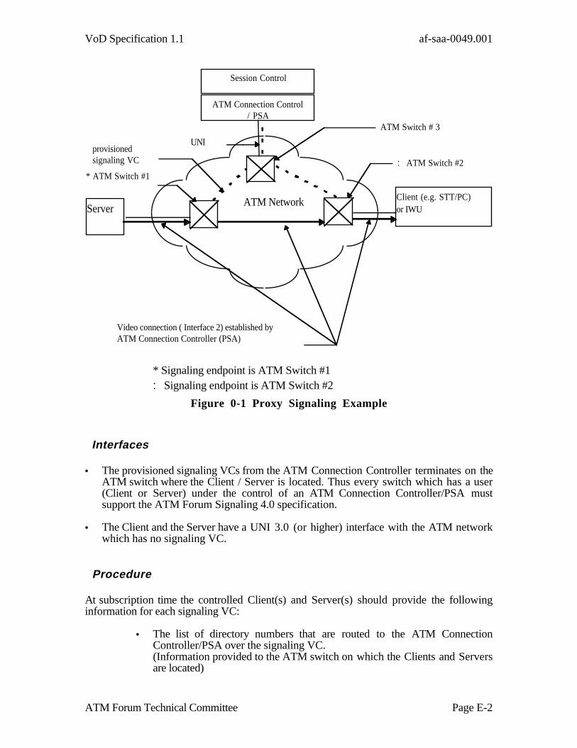
VoD Specification 1.1 af-saa-0049.001
ATM Forum Technical Committee Page E-2
Session Control
ATM Connection Control/ PSA
ServerClient (e.g. STT/PC)or IWU
* ATM Switch #1
♣ ATM Switch #2
ATM Switch # 3
provisionedsignaling VC
UNI
Video connection ( Interface 2) established byATM Connection Controller (PSA)
ATM Network
* Signaling endpoint is ATM Switch #1♣ Signaling endpoint is ATM Switch #2
Figure 0-1 Proxy Signaling Example
Interfaces
• The provisioned signaling VCs from the ATM Connection Controller terminates on theATM switch where the Client / Server is located. Thus every switch which has a user(Client or Server) under the control of an ATM Connection Controller/PSA mustsupport the ATM Forum Signaling 4.0 specification.
• The Client and the Server have a UNI 3.0 (or higher) interface with the ATM networkwhich has no signaling VC.
Procedure
At subscription time the controlled Client(s) and Server(s) should provide the followinginformation for each signaling VC:
• The list of directory numbers that are routed to the ATM ConnectionController/PSA over the signaling VC.(Information provided to the ATM switch on which the Clients and Serversare located)
VoD Specification 1.1 af-saa-0049.001
ATM Forum Technical Committee Page E-3
• A mapping of VPCI values to a specific UNI and VPI combination for eachVP controlled by the ATM Connection Controller/PSA over a signaling VC.(Information provided to the ATM Connection Controller/PSA)
• The VPI and VCI for the signaling VC and of the associated ILMI VC (ifpresent).
The switches where the clients and servers are directly connected must support ATMForum Signaling 4.0 (non associated signaling).
Message flow
Assuming that neither the VIP nor the C1...Cn end users have signaling capability, a callestablished by the VIP to the end user would require the following set of messageexchanges.
Call/Connection at the originating interface
The ATM Connection Manager/PSA sends over the signaling VC which corresponds to theServer a SETUP message with the address of the Client in the called user address IE, theVIP VPCI and possibly VCI in the connection identifier IE.
The ATM switch to which the Server is connected will send back:
• a CALL PROCEEDING or a CONNECT message specifying the VCI andconfirming the VPCI or confirming both VPCI/VCIor
• a RELEASE COMPLETE message denying the availability of the requestedVPCI/VCI.
For more detail please refer to §5.1.2.2/Q.2931.
Call/Connection at the destination interface
On an incoming call, offered to the ATM Connection Controller, the ATM network canonly specify one of the following two options:
Option 1:Only case a): << Exclusive VPCI, any VCI >> AND case c): << No indication >> of§5.2.3.2/Q.2931 shall be used. Option 2:Only case c) << No indication is included >> of §5.2.3.2/ Q.2931 shall be used.
In the incoming call offering side, the node to which the Client is connected shall sendthrough the client related signaling VC a SETUP message with the Client address as thecalled user address and an explicit VPCI (option (a) §5.2.3.2/Q.2931) or no connectionidentifier (option (c) §5.2.3.2/Q.2931). In the first message sent back to the network, theATM connection Controller/PSA shall specify the connection identifier to be used.

VoD Specification 1.1 af-saa-0049.001
ATM Forum Technical Committee Page E-4
Message Sequence Chart
In the following diagram a message is given only two IEs (for simplicity) : the called useraddress and the connection identifier.
ACC Nserver NClient ACC| |
SETUP(@Client, VPCIv/VCIv*) | |------------------------------------> | |CALL PROCEED(VPCIv/VCIv) | |
<------------------------------------- | |SETUP(@Client, VPCIe~)
| |------------------------------->| |CALL PROCEEDING(VPCIe/VCIe)| |<------------------------------| || |CONNECT| |<-------------------------------| |CONNECT ACKNOWLEDGE
CONNECT | |-------------------------------><------------------------------------- | |
CONNECT ACKNOWLEDGE | |--------------------------------------> | |
ACC = ATM Connection ControllerNServer = network node to which the server (VIP) is connectedNClient= network node to which the client is connectedVPCI/VCI* = Option a) or b) of §5.1.2.4.2/Q.2931 is usedVPCI~ = Option a) or c) If option c) is used no connection identifier IE is sent by the
network. A connection identifier IE with the VPCI/VCI of the End User will be sent bythe first message in response to the SETUP message sent by the Connection Manager.
CALL PROCEEDING is an optional message in both directions.

VoD Specification 1.1 af-saa-0049.001
ATM Forum Technical Committee Page F-1
Table of VoD Service Attributes [Informative]
The attributes of the Video on Demand Service can be summarized using the tabular formatdescribed in I.211 and F.722.
SERVICE ATTRIBUTES VALUES OF ATTRIBUTES
1. Information Transfer Capability, ServiceComponents (SC)1.1 Mandatory Service Components SC no. 1 High Quality Video 4
SC no. 2 High Quality Audio 2
1.2 Optional Service Components SC no. 3 to n Unrestricted DigitalInformation 2
2. Information Transfer Mode ATM2.1 Connection Mode Connection Oriented2.2 Broadband Transfer Capability (ServiceSpecific)
SC no. 1&2 : CBRSC no. 3-n: implementation specific
3. Information Transfer Rate (servicespecific)
SC no. 1&2: Peak Cell Rate (CBR)SC no 3-n: implementation specific
4. Structure (service specific) SC no: 1&2 multiplexed as MPEG-2 SingleProgram Transport Stream via AAL-5 in oneVC.SC no. 3-n : implementation specific
5. Establishment of Communication demand, reserved6. Symmetry SC no. 1&2: unidirectional
SC 3-n: unidirectional, bi-directionalsymmetric
7. Communication configuration point-to-point
Access Attributes8. Access Channels and rates8.1 for user information VC no. 1: SC no. 1&2
VC no. 3-n : SC no. 3-n8.2 for signaling signaling VC9. Access protocols9.1 Signaling access protocol - physicallayer
ATM Forum Signaling 4.0
9.2 signaling access protocol - ATM layer ATM Forum Signaling 4.09.3 signaling access protocol ATM Forum Signaling 4.09.4 signaling access protocol - layer 3 aboveAAL
ATM Forum Signaling 4.0
9.5 information access protocols - PHYlayer
for further study
9.6 Information Access protocols - ATMlayer
I.150, 1.361
9.7 Information Access Protocols - AAL AAL-5
4 Service components SC1 and SC2 are multiplexed as MPEG-2 SPTS. An MPEG-2 SPTS may alsocontain Private Data. In this case, MPEG-2 Private Data could be considered a unidirectional instance of SC3.
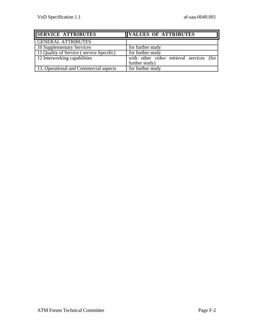
VoD Specification 1.1 af-saa-0049.001
ATM Forum Technical Committee Page F-2
SERVICE ATTRIBUTES VALUES OF ATTRIBUTES
GENERAL ATTRIBUTES10 Supplementary Services for further study11 Quality of Service ( service Specific) for further study12 Interworking capabilities with other video retrieval services (for
further study)13. Operational and Commercial aspects for further study

VoD Specification 1.1 af-saa-0049.001
ATM Forum Technical Committee Page G-1
Interim Connection Management Arrangements Prior to A TM Forum Signaling 4.0 Specification [Informative]
First Party Interim Signaling Arrangements
To use UNI 3.1 for 1st Party Connection Setup for Video-on-Demand, the signalingparameters should be set in accordance with section 8 (ATM Signaling Setup InformationElements) but with the following use of the Broadband High Layer Information (B-HLI),Low Layer Information (B-LLI) and the Quality of Service Parameter.
1) To allow the VOD Application ID and a correlation ID to be exchanged in an UNI 3.1environment,:
• Set the Broadband Low Layer information I.E. to -
Field Value Notes
User Information Layer3 Protocol
‘01011’b ISO/IEC TR 9577(Protocol Identification in theNetwork Layer)
ISO/IEC TR 9577 IPI ‘10000000’b Initial Protocol Identifierin Bytes 7a and 7b
SNAP ID ‘00’b Octet 8 SNAP
OUI Type ‘00A03E’x ATM Forum OUI
PID ‘0002’x Lower two bytes of the ATMForum VOD ID
• The B-HLI shall contain a correlation id such as the 7 byte DSM-CCsession/resource ID (as defined in Annex D of [10]) by setting the high layerinformation type to “user specific”

VoD Specification 1.1 af-saa-0049.001
ATM Forum Technical Committee Page G-2
Field Value Notes
Higher LayerInformation Type
‘0000001’b
User Specific
Octets 6 - 13 Max. of 7 byte correlation id:
• DSM-CC Resource/SessionIdentification
• H.245 Correlation Id• etc.
2) For the Quality of Service Parameter, use QoS Class in accordance with what yournetwork provider has defined for carrying VOD services.
Proxy Signaling Interim Arrangements
Prior to the availability of ATM Forum Signaling 4.0, proxy signaling can beimplemented by using the existing text in the current ATM Forum Signaling 4.0 draft onproxy signaling. This is considered a complete and self contained specification of theproxy signaling capability. It requires the use of existing procedures defined by ITU-T intheir Recommendation Q.2931.
ATM Forum UNI 3.1 mandates that ATM connection resources (e.g. VPI/VCI) areassigned only by the network. This limitation does not exist in ATM Forum Signaling 4.0,since it allows either the user or the network to assign these parameters. Proxy signalingrequires VC negotiation capability which enables the Proxy Signaling Agent (PSA) , auser of the ATM network , to select the interface and VPI/VCI for an incoming oroutgoing call to use. The ITU-T recommendation Q.2931 supports VC negotiationcapability and hence, can be used, in the interim, in place of the ATM Forum Signaling4.0 specification.
Third Party Interim PVC Arrangements
Where SVC capability is not available, the client to server connection may be a PVC, providedthat PVCs with acceptably low latency can be configured dynamically between the end-userand the server. In this case, the dynamic configuration of PVCs takes place using managementplane procedures.

VoD Specification 1.1 af-saa-0049.001
ATM Forum Technical Committee Page G-3
i ................... ITU-T Recommendation G.803, “Digital Networks - Architectures of Transport
Networks Based on the synchronous Digital Hierarchy (SDH)”, 03/93.ii .................. ATM Forum “User-Network Interface Specification”, version 3.0 Prentice Hall
September 1993.iii .................. Bellcore TA-NWT-001110 “Broadband ISDN Switching System Generic
Requirements”, Issue 2 August 31, 1993, Table 5.8 pg 60.iv .................. Bellcore TA-NWT-001110 “Broadband ISDN Switching System Generic
Requirements” Issue 2 August 31,1993, table 5.12 pg 62.