technical data notebook - pima county
TRANSCRIPT

TECHNICAL DATA NOTEBOOK:
LETTER OF MAP REVISION
for
Flowing Wells Wash & Runway Drive Area
Tucson, Arizona
11-14-2016
EXPIRES 12-31-2019
November 2016
Prepared for: Prepared by:
Pima County Regional Flood Control District JE Fuller/ Hydrology & Geomorphology
201 N. Stone Ave, 9th Floor 40 E. Helen Street
Tucson, AZ 85701 Tucson, Arizona 85705
520-724-4600 520-623-3112

Page i
TABLE OF CONTENTS
SECTION 1: INTRODUCTION .............................................................................................. 1-1
1.1 Study Purpose .......................................................................................................... 1-1
1.2 Study Authority ....................................................................................................... 1-1
1.3 Study Location ......................................................................................................... 1-1
1.4 Methodology............................................................................................................. 1-3
1.5 Acknowledgements .................................................................................................. 1-3
1.6 Study results ............................................................................................................. 1-3
SECTION 2: ADWR/FEMA FORMS ..................................................................................... 2-1
2.1 Study Documentation Abstract for FEMA Submittals ........................................ 2-1
2.2 FEMA Forms ........................................................................................................... 2-2
SECTION 3: MAPPING AND SURVEY INFORMATION ................................................. 3-1
3.1 Digital Projection Information ............................................................................... 3-1
3.2 Field Survey Information........................................................................................ 3-1
3.3 Mapping ................................................................................................................... 3-1
SECTION 4: HYDROLOGY ................................................................................................... 4-1
4.1 Method Description ................................................................................................. 4-1
4.2 Parameter Estimation ............................................................................................. 4-3
4.3 Problems Encountered During the Study ............................................................. 4-4
4.4 Calibration ............................................................................................................... 4-4
4.5 Results ...................................................................................................................... 4-4
SECTION 5: HYDRAULIC ANALYSIS ................................................................................ 5-1
5.1 Method Description ................................................................................................. 5-1
5.2 Work Study Maps ................................................................................................... 5-1
5.3 Parameter Estimation ............................................................................................. 5-1
5.4 Cross-Section Description ....................................................................................... 5-1
5.5 Modeling Considerations ........................................................................................ 5-1
5.6 Floodway Modeling ................................................................................................. 5-2
5.7 Issued Encountered During the Study ................................................................... 5-2
5.8 Calibration ............................................................................................................... 5-2
5.9 Final Results ............................................................................................................. 5-2
SECTION 6: SEDIMENT TRANSPORT/EROSION ........................................................... 6-1
SECTION 7: DRAFT FIS ......................................................................................................... 7-1
7.1 Summary of Discharges .......................................................................................... 7-1
7.2 Floodway Data ......................................................................................................... 7-1
7.3 Annotated Flood Insurance Rate Maps ................................................................. 7-1
7.4 Flood Profiles ........................................................................................................... 7-1
SECTION 8: ESA Compliance ................................................................................................. 7-1

Page ii
LIST OF FIGURES Figure 1.1: Vicinity Map ........................................................................................................... 1-2
Figure 1.2: Study Area Location Map ..................................................................................... 1-2
Figure 4.1: FLO-2D Watershed Model Boundary ................................................................. 4-2
LIST OF APPENDICES Appendix A: References
Appendix B: General Documentation and Correspondence
Appendix C: As-Built Data
Appendix D: FLO-2D Model for Runway Drive Area
Appendix E: HEC-RAS Model for Flowing Wells Wash
Appendix F: Workmaps
Appendix G: Annotated FIRMs
Appendix H: Shape Files

LOMR – Flowing Wells Wash & Runway Drive Area, AZ
Page 1-1
SECTION 1: INTRODUCTION
1.1 Study Purpose
The purpose of this report is to document the analysis associated with revision of the existing
flood insurance mapping along the Flowing Wells Wash and the Runway Drive Area. The
subject area is located within Sections 21, 22, 27 & 28, Township 13 South, Range 13 East, Gila
& Salt River Baseline, Tucson, Arizona. The revisions are provided based on structure
improvements and better data.
1.2 Study Authority
This report was prepared by JE Fuller/Hydrology & Geomorphology, Inc under contract to the
Pima County Regional Flood Control District.
The State of Arizona has delegated the responsibility to each county flood control district to
delineate or require the delineation of floodplains and to regulate development within floodplains
(ARS § 48-3609).
1.3 Study Location
Figures 1.1 shows the general vicinity of the project area. Figure 1.2. shows the study area
location. The study area has a semi-arid desert climate with an average annual precipitation of
generally less than 12 inches. Precipitation is typically divided between two seasons with
comparable rainfall amounts: summer and winter. Summer storms are associated with warm,
moist tropical air masses that enter the state from the Gulf of Mexico and Gulf of California,
producing moderate to intense localized thundershowers. Winter precipitation usually originates
from the Pacific Ocean and produces light to moderate precipitation over relatively large areas.
A third source of precipitation is from dissipating tropical storm and/or hurricane remnants,
which typically occur in fall, and which generate moderate to high rainfall intensities of
moderate to long duration.

LOMR – Flowing Wells Wash & Runway Drive Area, AZ
Page 1-2
Figure 1.1 Vicinity Map
Figure 1.2 Project Location Map

LOMR – Flowing Wells Wash & Runway Drive Area, AZ
Page 1-3
1.4 Methodology
This study used methods outlined in the FEMA Guidelines (Reference 1). HEC-RAS 4.1 was
used to perform the hydraulic modeling of the Flowing Wells Wash. FLO-2D Pro version,
which has been approved for hydrology and hydraulics by FEMA for use in Pima County, was
utilized to perform the hydraulic and hydrologic analysis for the Runway Drive area.
The study reach for the Flowing Wells Wash (FWW) extends from the Santa Cruz River
confluence to Ft. Lowell Road and includes (1) the Zone AH area located between Interstate 10
and Higgins Lane, and (2) the Zone AE area located between Higgins Lane and Ft. Lowell Road.
The study area for the Runway Drive Area watershed is bounded by Gardner Lane, Prince Road,
I-10 and Romero Road and includes all of the Zone AO (Depth 1), AO (Depth 2), and shaded
Zone X areas within this boundary.
The two affected flood-hazard areas were originally mapped in 1988 and first appeared on
Community-Panel No. 040076-0010C. The FWW was mapped by detailed methods, using
HEC-2 and a regulatory discharge that ranged from 5845 cfs at the Santa Cruz River to 4355 cfs
between Higgins Lane and Ft. Lowell Road. The original FWW modeling determined that
approximately half of the 5845 cfs or 3230 cfs overtopped the north bank of the FWW just
upstream of the upstream of the then Southern Pacific Railroad (now Union Pacific
Railroad[UPRR]) drainage structure, which was the basis for the AO zone designation between
the wash and Prince Road. The Runway Drive Area was mapped by approximate methods using
a variety of discharges ranging from 15 cfs to 1090 cfs that were collectively used to map the
Zone AO and X (shaded) areas. In 1994, the regulatory discharge for the FWW was
significantly reduced to its current value (3013 cfs) and the reach upstream of Higgins Lane was
remapped to account for the reduced discharge and channel improvements between Romero
Road and Ft. Lowell Road. As a result of that restudy, the zone designation from Higgins Lane
upstream was changed from AH to AE. However, the area downstream of Higgins Lane was
never remapped to account for the reduced (effective) discharge. In 1999, a small portion of the
Runway Drive Area was remapped by LOMR Case No. 99-09-200P to account for channel
improvements along the south side of Price Street. All of these revisions are reflected on the
effective maps (i.e., Panel Nos. 04019C2277L, 04019C2279L, and 04019C2283L).
1.5 Acknowledgements
This study was funded by the Pima County Regional Flood Control District.
1.6 Study results
The study resulted in revisions to the existing Zone AE, AH and AO delineations in the project
area. The resulting revised zone delineations are documented herein.

LOMR – Flowing Wells Wash & Runway Drive Area, AZ
Page 2-1
SECTION 2: ADWR/FEMA FORMS
2.1 Study Documentation Abstract for FEMA Submittals
Study Documentation Abstract
For FEMA Submittals
Initial
Study Restudy CLOMR LOMR X Other
2.1.1 Date Study Accepted
2.1.2 Study Prime Contractor JE Fuller / Hydrology and Geomorphology, Inc.
Contact(s) John Wallace, P.E.
Address 40 E Helen St
Tucson, AZ 85705
Phone 520.623.3112
Internal Reference Number P1750.01-3
2.1.2 Study Sub-Contractor None
Contact(s)
Address
Phone
Internal Reference Number
2.1.2 Sub Study Sub-Contractor
Contact(s)
Address
Phone
Internal Reference Number
2.1.3 FEMA Technical Review
Contractor To be determined
Contact(s)
Address
Phone
Internal Reference Number
2.1.4 FEMA Regional Reviewer
Phone
2.1.5 State Technical Reviewer None
Phone
2.1.6 Local Technical Reviewer Pima County Regional Flood Control District (PCRFCD)
Evan Canfield
Phone (520) 724-4600
2.1.7 Reach Description Flowing Wells Wash & Runway Drive Area, Panel #s
04019C1667L, 1669L & 1688L
2.1.8 USGS Quad Sheet(s) with
original photo date & latest
photo revision date
Tucson & Tucson East, published 1978
2.1.9 Unique Conditions and
Problems
Broad, shallow flow indicating need for 2-dimensional modeling
approach in Runway Drive area
2.1.10 Coordination of Peak
Discharges (Agency, Date,
Comments)
PCRFCD Coordination; Discussed use of HEC-RAS for Flowing
Wells Wash and FLO-2D for Runway Drive area.

LOMR – Flowing Wells Wash & Runway Drive Area, AZ
Page 2-2
2.2 FEMA Forms
FEMA forms MT2, Forms 1 & 2 are included within this section

FEMA Form 086-0-27, (2/2011) Previously FEMA Form 81-89 MT-2 Form 1 Page 1 of 3
U.S. DEPARTMENT OF HOMELAND SECURITY FEDERAL EMERGENCY MANAGEMENT AGENCY
OVERVIEW & CONCURRENCE FORM
O.M.B No. 1660-0016
Expires February 28, 2014
PAPERWORK BURDEN DISCLOSURE NOTICE
Public reporting burden for this form is estimated to average 1 hours per response. The burden estimate includes the time for reviewing instructions, searching existing data sources, gathering and maintaining the needed data, and completing, reviewing, and submitting the form. You are not required to respond to this collection of information unless it displays a valid OMB control number. Send comments regarding the accuracy of the burden estimate and any suggestions for reducing this burden to: Information Collections Management, Department of Homeland Security, Federal Emergency Management Agency, 1800 South Bell Street, Arlington, VA 20958-3005, Paperwork Reduction Project (1660-0016). Submission of the form is required to obtain or retain benefits under the National Flood Insurance Program. Please do not send your completed survey to the above address.
PRIVACY ACT STATEMENT
AUTHORITY: The National Flood Insurance Act of 1968, Public Law 90-448, as amended by the Flood Disaster Protection Act of 1973, Public Law 93-234.
PRINCIPAL PURPOSE(S): This information is being collected for the purpose of determining an applicant's eligibility to request changes to National Flood Insurance Program (NFIP) Flood Insurance Rate Maps (FIRM).
ROUTINE USE(S): The information on this form may be disclosed as generally permitted under 5 U.S.C § 552a(b) of the Privacy Act of 1974, as amended. This includes using this information as necessary and authorized by the routine uses published in DHS/FEMA/NFIP/LOMA-1 National Flood Insurance Program (NFIP); Letter of Map Amendment (LOMA) February 15, 2006, 71 FR 7990.
DISCLOSURE: The disclosure of information on this form is voluntary; however, failure to provide the information requested may delay or prevent FEMA from processing a determination regarding a requested change to a (NFIP) Flood Insurance Rate Maps (FIRM).
A. REQUESTED RESPONSE FROM DHS-FEMA
This request is for a (check one):
CLOMR: A letter from DHS-FEMA commenting on whether a proposed project, if built as proposed, would justify a map revision, or proposed hydrology changes (See 44 CFR Ch. 1, Parts 60, 65 & 72).
LOMR: A letter from DHS-FEMA officially revising the current NFIP map to show the changes to floodplains, regulatory floodway or flood
elevations. (See 44 CFR Ch. 1, Parts 60, 65 & 72)
B. OVERVIEW
1. The NFIP map panel(s) affected for all impacted communities is (are):
Community No. Community Name State Map No. Panel No. Effective Date
Example: 480301 480287
City of Katy Harris County
TX TX
48473C 48201C
0005D 0220G
02/08/83 09/28/90
040073 Pima County and Incorporated Areas AZ 04019C 1667L 06/16/11
040073 Pima County and Incorporated Areas AZ 04019C 1669L 06/16/11
2. a. Flooding Source: Pima Air Museum Wash b. Types of Flooding: Riverine Coastal Shallow Flooding (e.g., Zones AO and AH)
Alluvial fan Lakes Other (Attach Description) 3. Project Name/Identifier: Flowing Wells Wash & Runway Drive Area. 4. FEMA zone designations affected: A, AH, AE (choices: A, AH, AO, A1-A30, A99, AE, AR, V, V1-V30, VE, B, C, D, X) 5. Basis for Request and Type of Revision: a. The basis for this revision request is (check all that apply)
Physical Change Improved Methodology/Data Regulatory Floodway Revision Base Map Changes
Coastal Analysis Hydraulic Analysis Hydrologic Analysis Corrections
Weir-Dam Changes Levee Certification Alluvial Fan Analysis Natural Changes
New Topographic Data Other (Attach Description)
Note: A photograph and narrative description of the area of concern is not required, but is very helpful during review.


FEMA Form 086-0-27, (2/2011) Previously FEMA Form 81-89 MT-2 Form 1 Page 3 of 3
Ensure the forms that are appropriate to your revision request are included in your submittal.
Form Name and (Number) Required if …
Riverine Hydrology and Hydraulics Form (Form 2) New or revised discharges or water-surface elevations
Riverine Structures Form (Form 3) Channel is modified, addition/revision of bridge/culverts, addition/revision of levee/floodwall, addition/revision of dam
Coastal Analysis Form (Form 4) New or revised coastal elevations
Coastal Structures Form (Form 5) Addition/revision of coastal structure
Alluvial Fan Flooding Form (Form 6) Flood control measures on alluvial fans
Seal (Optional)

FEMA Form 086-0-27A, (2/2011) Previously FEMA Form 81-89 MT-2 Form 2 Page 1 of 3
U.S. DEPARTMENT OF HOMELAND SECURITY FEDERAL EMERGENCY MANAGEMENT AGENCY
RIVERINE HYDROLOGY & HYDRAULICS FORM O.M.B No. 1660-0016
Expires February 28, 2014
PAPERWORK BURDEN DISCLOSURE NOTICE
Public reporting burden for this form is estimated to average 3.5 hours per response. The burden estimate includes the time for reviewing instructions, searching existing data sources, gathering and maintaining the needed data, and completing, reviewing, and submitting the form. You are not required to respond to this collection of information unless a valid OMB control number appears in the upper right corner of this form. Send comments regarding the accuracy of the burden estimate and any suggestions for reducing this burden to: Information Collections Management, Department of Homeland Security, Federal Emergency Management Agency, 1800 South Bell Street, Arlington VA 20958-3005, Paperwork Reduction Project (1660-0016). Submission of the form is required to obtain or retain benefits under the National Flood Insurance Program. Please do not send your completed survey to the above address.
PRIVACY ACT STATEMENT
AUTHORITY: The National Flood Insurance Act of 1968, Public Law 90-448, as amended by the Flood Disaster Protection Act of 1973, Public Law 93-234.
PRINCIPAL PURPOSE(S): This information is being collected for the purpose of determining an applicant's eligibility to request changes to National Flood Insurance Program (NFIP) Flood Insurance Rate Maps (FIRM).
ROUTINE USE(S): The information on this form may be disclosed as generally permitted under 5 U.S.C § 552a(b) of the Privacy Act of 1974, as amended. This includes using this information as necessary and authorized by the routine uses published in DHS/FEMA/NFIP/LOMA-1 National Flood Insurance Program (NFIP); Letter of Map Amendment (LOMA) February 15, 2006, 71 FR 7990.
DISCLOSURE: The disclosure of information on this form is voluntary; however, failure to provide the information requested may delay or prevent FEMA from processing a determination regarding a requested change to a NFIP Flood Insurance Rate Maps (FIRM).
Flooding Source: Flowing Wells Wash & Runway Drive Area
Note: Fill out one form for each flooding source studied
A. HYDROLOGY
1. Reason for New Hydrologic Analysis (check all that apply)
Not revised (skip to section B) No existing analysis Improved data
Alternative methodology Proposed Conditions (CLOMR) Changed physical condition of watershed
2. Comparison of Representative 1%-Annual-Chance Discharges
Location Drainage Area (Sq. Mi.) Effective/FIS (cfs) Revised (cfs)
Flowing Wells Wash 6.1 3013 3013
Runway Drive Area NA NA NA
3. Methodology for New Hydrologic Analysis (check all that apply)
Statistical Analysis of Gage Records Precipitation/Runoff Model � Specify Model: FLO-2D v2009 for RunwayDr
Regional Regression Equations Other (please attach description)
Please enclose all relevant models in digital format, maps, computations (including computation of parameters), and documentation to support the new analysis.
4. Review/Approval of Analysis
If your community requires a regional, state, or federal agency to review the hydrologic analysis, please attach evidence of approval/review. 5. Impacts of Sediment Transport on Hydrology
Is the hydrology for the revised flooding source(s) affected by sediment transport? Yes No If yes, then fill out Section F (Sediment Transport) of Form 3. If No, then attach your explanation..

FEMA Form 086-0-27A, (2/2011) Previously FEMA Form 81-89 MT-2 Form 2 Page 2 of 3
B. HYDRAULICS
1. Reach to be Revised
Description Cross Section Water-Surface Elevations (ft.)
Effective Proposed/Revised
Downstream Limit* Union Pacifc Railroad. NA NA NA
Upstream Limit* Fort Lowell Road F 2304 2304
*Proposed/Revised elevations must tie-into the Effective elevations within 0.5 foot at the downstream and upstream limits of revision.
2. Hydraulic Method/Model Used: HEC-RAS (Flowing Wells Wash) & FLO-2D (Runway Dr)
3. Pre-Submittal Review of Hydraulic Models*
DHS-FEMA has developed two review programs, CHECK-2 and CHECK-RAS, to aid in the review of HEC-2 and HEC-RAS hydraulic models, respectively. We recommend that you review your HEC-2 and HEC-RAS models with CHECK-2 and CHECK-RAS.
4. Models Submitted Natural Run Floodway Run Datum
Duplicate Effective Model* File Name:
______NA__ ____ Plan Name:
______________
File Name: _____NA__________
___
Plan Name: ______________ __________
Corrected Effective Model* File Name:
________NA_____ Plan Name:
______________
File Name: ________NA_______
___
Plan Name: ______________ __________
Existing or Pre-Project Conditions Model
File Name: FWWashLOMR
Plan Name: ______________
File Name: _________NA______
___
Plan Name: ______________ __________
Revised or Post-Project Conditions Model
File Name: FWWashLOMR
Plan Name: ______________
File Name: ________NA_______
___
Plan Name: ______________ __________
Other - (attach description) File Name:
Runway Dr FLO-2D Plan Name:
File Name: ________NA_______
___
Plan Name: ______________ __________
* For details, refer to the corresponding section of the instructions. Digital Models Submitted? (Required)
C. MAPPING REQUIREMENTS
A certified topographic work map must be submitted showing the following information (where applicable): the boundaries of the effective, existing, and proposed conditions 1%-annual-chance floodplain (for approximate Zone A revisions) or the boundaries of the 1%- and 0.2%-annual-chance floodplains and regulatory floodway (for detailed Zone AE, AO, and AH revisions); location and alignment of all cross sections with stationing control indicated; stream, road, and other alignments (e.g., dams, levees, etc.); current community easements and boundaries; boundaries of the requester's property; certification of a registered professional engineer registered in the subject State; location and description of reference marks; and the referenced vertical datum (NGVD, NAVD, etc.). Digital Mapping (GIS/CADD) Data Submitted (preferred) Topographic Information: Pima Association of Governments 2008 DEM
Source: Pima Association of Governments Date: 2008
Accuracy: +/1 one foot
Note that the boundaries of the existing or proposed conditions floodplains and regulatory floodway to be shown on the revised FIRM and/or FBFM must tie-in with the effective floodplain and regulatory floodway boundaries. Please attach a copy of the effective FIRM and/or FBFM, at the same scale as the original, annotated to show the boundaries of the revised 1%-and 0.2%-annual-chance floodplains and regulatory floodway that tie-in with the boundaries of the effective 1%-and 0.2%-annual-chance floodplain and regulatory floodway at the upstream and downstream limits of the area on revision.
Annotated FIRM and/or FBFM (Required)

FEMA Form 086-0-27A, (2/2011) Previously FEMA Form 81-89 MT-2 Form 2 Page 3 of 3
D. COMMON REGULATORY REQUIREMENTS*
1. For LOMR/CLOMR requests, do Base Flood Elevations (BFEs) increase? Yes No
a. For CLOMR requests, if either of the following is true, please submit evidence of compliance with Section 65.12 of the NFIP regulations:
• The proposed project encroaches upon a regulatory floodway and would result in increases above 0.00 foot compared to pre-project conditions.
• The proposed project encroaches upon a SFHA with or without BFEs established and would result in increases above 1.00 foot compared to pre-project conditions.
b. Does this LOMR request cause increase in the BFE and/or SFHA compared with the effective BFEs and/or SFHA? Yes No
If Yes, please attach proof of property owner notification and acceptance (if available). Elements of and examples of property owner notifications can be found in the MT-2 Form 2 Instructions.
2. Does the request involve the placement or proposed placement of fill? Yes No
If Yes, the community must be able to certify that the area to be removed from the special flood hazard area, to include any structures or proposed structures, meets all of the standards of the local floodplain ordinances, and is reasonably safe from flooding in accordance with the NFIP regulations set forth at 44 CFR 60.3(A)(3), 65.5(a)(4), and 65.6(a)(14). Please see the MT-2 instructions for more information.
3. For LOMR requests, is the regulatory floodway being revised? Yes No
If Yes, attach evidence of regulatory floodway revision notification. As per Paragraph 65.7(b)(1) of the NFIP Regulations, notification is required for requests involving revisions to the regulatory floodway. (Not required for revisions to approximate 1%-annual-chance floodplains [studied Zone A designation] unless a regulatory floodway is being established. Elements and examples of regulatory floodway revision notification can be found in the MT-2 Form 2 Instructions.)
4. For CLOMR requests, please submit documentation to FEMA and the community to show that you have complied with Sections 9 and 10 of the Endangered Species Act (ESA).
For actions authorized, funded, or being carried out by Federal or State agencies, please submit documentation from the agency showing its compliance with Section 7(a)(2) of the ESA. Please see the MT-2 instructions for more detail.
* Not inclusive of all applicable regulatory requirements. For details, see 44 CFR parts 60 and 65.

FEMA Form 086-0-27B, (2/2011) Previously FEMA Form 81-89B MT-2 Form 3 Page 1 of 11
DEPARTMENT OF HOMELAND SECURITY
FEDERAL EMERGENCY MANAGEMENT AGENCY
RIVERINE STRUCTURES FORM
O.M.B. NO. 1660-0016 Expires February 28, 2014
PAPERWORK BURDEN DISCLOSURE NOTICE Public reporting burden for this form is estimated to average 7 hours per response. The burden estimate includes the time for reviewing instructions, searching existing data sources, gathering and maintaining the needed data, and completing, reviewing, and submitting the form. You are not required to respond to this collection of information unless a valid OMB control number appears in the upper right corner of this form. Send comments regarding the accuracy of the burden estimate and any suggestions for reducing this burden to: Information Collections Management, Department of Homeland Security, Federal Emergency Management Agency, 1800 South Bell Street, Arlington, VA 20598-3005, Paperwork Reduction Project (1660-0016). Submission of the form is required to obtain or retain benefits under the National Flood Insurance Program. Please do not send your completed survey to the above address.
PRIVACY ACT STATEMENT
AUTHORITY: The National Flood Insurance Act of 1968, Public Law 90-448, as amended by the Flood Disaster Protection Act of 1973, Public Law 93-234.
PRINCIPAL PURPOSE(S): This information is being collected for the purpose of determining an applicant's eligibility to request changes to National Flood Insurance Program (NFIP) Flood Insurance Rate Maps (FIRM).
ROUTINE USE(S): The information on this form may be disclosed as generally permitted under 5 U.S.C § 552a(b) of the Privacy Act of 1974, as amended. This includes using this information as necessary and authorized by the routine uses published in DHS/FEMA/NFIP/LOMA-1 National Flood Insurance Program; Letter of Map Amendment (LOMA) February 15, 2006, 71 FR 7990.
DISCLOSURE: The disclosure of information on this form is voluntary; however, failure to provide the information requested may delay or prevent FEMA from processing a determination regarding a requested change to a NFIP Flood Insurance Rate Maps (FIRM).
Flooding Source: Flowing Wells Wash
Note: Fill out one form for each flooding source studied.
A. GENERAL Complete the appropriate section(s) for each Structure listed below:
Channelization...............complete Section B Bridge/Culvert................complete Section C Dam...............................complete Section D Levee/Floodwall.............complete Section E Sediment Transport........complete Section F (if required)
Description Of Modeled Structure 1. Name of Structure: Flowing Wells Wash - 4 cell pipe culvert (2 pipes added to original 2)
Type (check one): Channelization Bridge/Culvert Levee/Floodwall Dam Location of Structure: Union Pacific Railroad Downstream Limit/Cross Section: NA Upstream Limit/Cross Section: NA
2. Name of Structure: 2 - 10' x 8' RCBC @ 2 locations Type (check one): Channelization Bridge/Culvert Levee/Floodwall Dam Location of Structure: UA Farm Road & Romero Road Downstream Limit/Cross Section: NA Upstream Limit/Cross Section: NA
3. Name of Structure: 2 - 10' x 7' RCBC
Type (check one) Channelization Bridge/Culvert Levee/Floodwall Dam Location of Structure: Fort Lowell Road Downstream Limit/Cross Section: D Upstream Limit/Cross Section: E
NOTE: FOR MORE STRUCTURES, ATTACH ADDITIONAL PAGES AS NEEDED.

FEMA Form 086-0-27B, (2/2011) Previously FEMA Form 81-89B MT-2 Form 3 Page 2 of 11
B. CHANNELIZATION Flooding Source: Flowing Wells Wash Name of Structure: NA 1. Hydraulic Considerations The channel was designed to carry (cfs) and/or the -year flood.
The design elevation in the channel is based on (check one):
Subcritical flow Critical flow Supercritical flow Energy grade line
If there is the potential for a hydraulic jump at the following locations, check all that apply and attach an explanation of how the hydraulic jump is controlled without affecting the stability of the channel.
Inlet to channel Outlet of channel At Drop Structures At Transitions
Other locations (specify): 2. Channel Design Plans Attach the plans of the channelization certified by a registered professional engineer, as described in the instructions. 3. Accessory Structures
The channelization includes (check one):
Levees [Attach Section E (Levee/Floodwall)] Drop structures Superelevated sections
Transitions in cross sectional geometry Debris basin/detention basin [Attach Section D (Dam/Basin)] Energy dissipator
Weir Other (Describe):
4. Sediment Transport Considerations
Are the hydraulics of the channel affected by sediment transport? Yes No
If yes, then fill out Section F (Sediment Transport) of Form 3. If No, then attach your explanation for why sediment transport was not considered.
C. BRIDGE/CULVERT Flooding Source: Flowing Wells Wash Name of Structure: Culverts listed on previous page 1. This revision reflects (check one):
Bridge/culvert not modeled in the FIS
Modified bridge/culvert previously modeled in the FIS
Revised analysis of bridge/culvert previously modeled in the FIS
2. Hydraulic model used to analyze the structure (e.g., HEC-2 with special bridge routine, WSPRO, HY8): HEC-RAS If different than hydraulic analysis for the flooding source, justify why the hydraulic analysis used for the flooding source could not analyze the structures. Attach justification.
3. Attach plans of the structures certified by a registered professional engineer. The plan detail and information should include the following
(check the information that has been provided):
Dimensions (height, width, span, radius, length) Distances Between Cross Sections
Shape (culverts only) Erosion Protection
Material Low Chord Elevations – Upstream and Downstream
Beveling or Rounding Top of Road Elevations – Upstream and Downstream
Wing Wall Angle Structure Invert Elevations – Upstream and Downstream
Skew Angle Stream Invert Elevations – Upstream and Downstream
Cross-Section Locations
4. Sediment Transport Considerations
Are the hydraulics of the structure affected by sediment transport? Yes No If Yes, then fill out Section F (Sediment Transport) of Form 3. If no, then attach an explanation.

FEMA Form 086-0-27B, (2/2011) Previously FEMA Form 81-89B MT-2 Form 3 Page 3 of 11
D. DAM/BASIN
Flooding Source: Flowing Wells Wash Name of Structure: NA 1. This request is for (check one): Existing dam/basin New dam/basin Modification of existing dam/basin 2. The dam/basin was designed by (check one): Federal agency State agency Private organization Local government agency Name of the agency or organization: 3. The Dam was permitted as (check one): Federal Dam State Dam
Provide the permit or identification number (ID) for the dam and the appropriate permitting agency or organization Permit or ID number __________________ Permitting Agency or Organization _____________________________
a. Local Government Dam Private Dam
Provided related drawings, specification and supporting design information.
4. Does the project involve revised hydrology? Yes No If Yes, complete the Riverine Hydrology & Hydraulics Form (Form 2).
Was the dam/basin designed using critical duration storm? (must account for the maximum volume of runoff)
Yes, provide supporting documentation with your completed Form 2.
No, provide a written explanation and justification for not using the critical duration storm.
5. Does the submittal include debris/sediment yield analysis? Yes No If Yes, then fill out Section F (Sediment Transport). If No, then attach your explanation for why debris/sediment analysis was not considered? 6. Does the Base Flood Elevation behind the dam/basin or downstream of the dam/basin change? Yes No If Yes, complete the Riverine Hydrology & Hydraulics Form (Form 2) and complete the table below.
Stillwater Elevation Behind the Dam/Basin FREQUENCY (% annual chance) FIS REVISED
10-year (10%)
50-year (2%)
100-year (1%)
500-year (0.2%)
Normal Pool Elevation
7. Please attach a copy of the formal Operation and Maintenance Plan
E. LEVEE/FLOODWALL

LOMR – Flowing Wells Wash & Runway Drive Area, AZ
Page 3-1
SECTION 3: MAPPING AND SURVEY INFORMATION
3.1 Digital Projection Information
All digital files were produced with the following projection;
• Projection = State Plane, Arizona Central Zone
• Horizontal Datum = NAD83-92(HARN)
• Units = International Feet
3.2 Field Survey Information
Field work was performed to confirm the location and size of culvert structures affecting the
study area.
3.3 Mapping
The topographic information used in conjunction with the re-mapping of both flooding sources
was based on 2008 DEM data obtained from the Pima Association of Governments (PAG). The
vertical datum is the North American Vertical Datum of 1988 (NAVD 88). The projection of the
data is as listed in Section 3.1 above. As-built plans for the drainage structures included in the
HEC-RAS modeling for the Flowing Wells Wash are provided in Appendix C. Some of the
plans were based on the National Geodetic Vertical Datum of 1929 (NGVD 29). A single
conversion factor of 2.19 feet is applicable to all of the older plan sets (i.e., the NAVD 88
elevations are approximately 2.19 feet higher than the NGVD 29 elevations shown on the older
plans). This conversion factor was taken from the table presented in Section 3.3 of the effective
FIS, dated September 28, 2012.

LOMR – Flowing Wells Wash & Runway Drive Area, AZ
Page 4-1
SECTION 4: HYDROLOGY
4.1 Hydrologic Modeling Methods
As part of this LOMR, the regulatory flood hazard area for the Flowing Wells Wash was remapped
using the effective discharge (3013 cfs) from Table 6 of the effective Flood Insurance Study (FIS) in
conjunction with updated topographic information. In addition, improvements to the drainage
structures beneath I-10 and the UPRR were also accounted for in the remapping. As noted in the
effective FIS, the 100-year return interval for the Flowing Wells Wash is the only return interval that
is applicable to this flooding source. The regulatory flood plain for the Flowing Wells Wash was
defined using HEC-RAS Version 4.1. The flood hazard area associated with the Runway Drive
Watershed was redefined using both the hydrologic and hydraulic components of FLO-2D, Pro
version (Reference 2). The FLO-2D model was used for the Runway Drive portion of the study
because of the relatively shallow, urban, dispersed flow conditions which occur in the watershed
tributary to the project. FLO-2D uses the full dynamic wave momentum equation and a central finite
difference routing scheme with eight potential flow directions to predict the progression of a flood
hydrograph over a system of square grid elements. The model is based on a grid of topographic data
points at evenly spaced intervals which are developed from digital elevation model data of the study
area. The model was constructed to model both rainfall-runoff and flow depths. The overall model
area is shown in Figure 4.1 and covers approximately 1.6 square miles. The FLO-2D model files are
contained in Appendix D.

16881669
16861667
1689
1687
Rillito River
Santa Cruz River
Navajo Wash
Flowing Wells Wash
Cemetry Wash
Speedway Wash
Cami
no D
e Oes
te Wa
sh
E I10W I10
N ST
ONE A
V
N OR
ACLE
RD
W PRINCE RD
N FL
OWIN
G W
ELLS
RD
W WETMORE RD
W RUTHRAUFF RD
W MIRACLE MILE
W I10 FRONTAGE RD
N FREEWAYN SILVERBELL RD
N BUSINESS CENTER DR
W GORET RD
W FORT LOWELL RD
LegendFIRM panel boundaries & #FLO-2D Model AreaWashesstreets
Figure 4.1 - Runway Drive Area - FLO-2D Model Boundary
1 inch = 2,000 feet¯
LOMR – Flowing Wells Wash & Runway Drive Area, AZ
Page 4-3
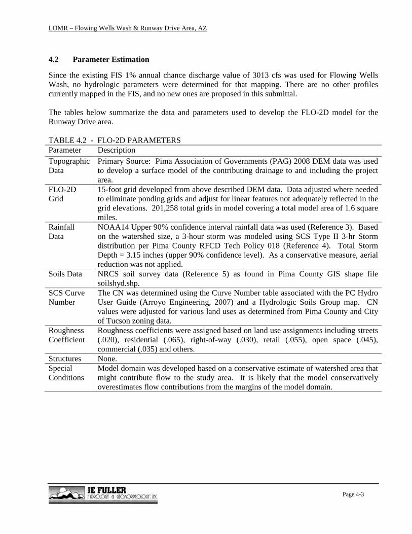
4.2 Parameter Estimation
Since the existing FIS 1% annual chance discharge value of 3013 cfs was used for Flowing Wells
Wash, no hydrologic parameters were determined for that mapping. There are no other profiles
currently mapped in the FIS, and no new ones are proposed in this submittal.
The tables below summarize the data and parameters used to develop the FLO-2D model for the
Runway Drive area.
TABLE 4.2 - FLO-2D PARAMETERS
Parameter Description
Topographic
Data
Primary Source: Pima Association of Governments (PAG) 2008 DEM data was used
to develop a surface model of the contributing drainage to and including the project
area.
FLO-2D
Grid
15-foot grid developed from above described DEM data. Data adjusted where needed
to eliminate ponding grids and adjust for linear features not adequately reflected in the
grid elevations. 201,258 total grids in model covering a total model area of 1.6 square
miles.
Rainfall
Data
NOAA14 Upper 90% confidence interval rainfall data was used (Reference 3). Based
on the watershed size, a 3-hour storm was modeled using SCS Type II 3-hr Storm
distribution per Pima County RFCD Tech Policy 018 (Reference 4). Total Storm
Depth = 3.15 inches (upper 90% confidence level). As a conservative measure, aerial
reduction was not applied.
Soils Data NRCS soil survey data (Reference 5) as found in Pima County GIS shape file
soilshyd.shp.
SCS Curve
Number
The CN was determined using the Curve Number table associated with the PC Hydro
User Guide (Arroyo Engineering, 2007) and a Hydrologic Soils Group map. CN
values were adjusted for various land uses as determined from Pima County and City
of Tucson zoning data.
Roughness
Coefficient
Roughness coefficients were assigned based on land use assignments including streets
(.020), residential (.065), right-of-way (.030), retail (.055), open space (.045),
commercial (.035) and others.
Structures None.
Special
Conditions
Model domain was developed based on a conservative estimate of watershed area that
might contribute flow to the study area. It is likely that the model conservatively
overestimates flow contributions from the margins of the model domain.

LOMR – Flowing Wells Wash & Runway Drive Area, AZ
Page 4-4
4.3 Problems Encountered
No special problems were encountered during the study.
4.4 Calibration
No known high watermarks or flood observations were available for the Runway Drive area. For that
reason, no direct calibration of model results could be made. However, a comparison of the model
results was made with runoff volume estimates in the region. Percent runoff from the Runway Drive
area FLO-2D model was compared to gaged data for watersheds in Tucson and southern Arizona.
The FLO-2D model produced greater percent runoff than gaged data in all cases reviewed. The
documentation of the runoff comparison is included in Appendix D and summarized in the table
below.
TABLE 4.4 - RUNOFF COMPARISON WITH GAGED DATA
Location Drainage Area
(mi2)
Description Runoff as % of
Rainfall
Runway Drive Area FLO-
2D (this study) 1.6
FLO-2D Model (15-ft grid) 56%
Tucson Arroyo at Vine
Avenue
8.2 USGS gaged watershed in Tucson, AZ,
August 12, 1972 event
42%
High School Wash
watershed
1.8 Measured runoff at watershed in Tucson, AZ
August 8, 1971 event (USACE, 1997)
41%
4.5 Final Results
Review of Section 4.4 shows that the FLO-2D model results in runoff rates that compare well with
gaged data. FLO-2D Model data (input/output) are included in Appendix D.

LOMR – Flowing Wells Wash & Runway Drive Area, AZ
Page 5-1
SECTION 5: HYDRAULIC ANALYSIS
5.1 Method Description
HEC-RAS 4.1 was used to perform the hydraulic modeling of the Flowing Wells Wash. The
revised mapping is Zone AE. The HEC-RAS model is included in Appendix E.
The FLO-2D model described in the previous section was utilized to perform the hydrologic and
hydraulic analysis for the Runway Drive area.. Depths determined from the FLO-2D model were
utilized to determine revised Zone AO and A delineations. The FLO-2D model is included in
Appendix D.
Per NFIP regulations, Section 65.12(a)(4), the City of Tucson is the only communities affected
by the proposed action.
Per NFIP regulations, Section 65.12(a)(5), there are no increases in base flood elevation
proposed.
5.2 Workmaps
Workmaps are included in Appendix F for both the Flowing Wells Wash HEC-RAS and Runway
Drive FLO-2D analyses.
5.3 Parameter Estimation
Roughness values for the Flowing Wells Wash HEC-RAS model are based on field investigation
and review of aerial photography. See Table 4.2 for data and parameters used to develop the
Runway Drive FLO-2D model.
5.4 Cross-Section Description
For the Flowing Wells Wash HEC-RAS model the model included new placement and
orientation along majority of revised reach with some duplicated FIS sections at upstream ties.
All new sections are from DTM and mapping.
5.5 Modeling Considerations
5.5.1 Hydraulic Jump and Drop Analysis - NA
5.5.2 Bridges and Culverts - A total of 4 culverts were included in the HEC-RAS model for the
map revision area. No structures were modeled in the Runway Drive area.
5.5.3 Levees and Dikes – NA
5.5.4 Non-Levee Embankments – NA
5.5.5 Islands and Flow Splits - NA

LOMR – Flowing Wells Wash & Runway Drive Area, AZ
Page 5-2
5.5.6 Ineffective Flow Areas – NA
5.5.7 Supercritical Flow - A limiting Froude Number of 0.9 was used in the FLO-2D modeling.
5.6 Floodway Modeling
NA
5.7 Issues Encountered During the Study
No special problems were encountered during the study.
5.8 Calibration
See discussion in Section 4.4
5.9 Final Results
The results of the modeling are reflected in the Workmaps and Annotated FIRMs provided in
Appendices F and G, respectively.

LOMR – Flowing Wells Wash & Runway Drive Area, AZ
Page 6-1
SECTION 6: SEDIMENT TRANSPORT/EROSION
No detailed erosion or sediment transport modeling was conducted as part of this study.

LOMR – Flowing Wells Wash & Runway Drive Area, AZ
p. 7-1
SECTION 7: DRAFT FIS
7.1 Summary of Discharges
No discharge data is provided within the existing FIS and no revised discharges are proposed.
7.2 Floodway Data
NA.
7.3 Annotated Flood Insurance Rate Maps
See Appendix G. Zones have been revised based on results of modeling. Where appropriate notes
indicating “100-yr flood contained in channel” notes have been added to clarify condition of flooding.
7.4 Flood Profiles
NA.
SECTION 8: ESA COMPLIANCE
Not applicable.

Appendix A
References

References
1. FEMA, 2002, Guidelines and Specifications for Flood Hazard Mapping Partners , February,
2002.
2. FLO-2D Users Manual, v2009.06, FLO-2D Inc., 2009.
3. National Oceanic and Atmospheric Administration (NOAA), National Weather Service,
NOAA Atlas 14, Precipitation Frequency Atlas of the United States, U.S. Department of
Commerce, 2004.
4. Pima County Regional Flood Control District, Technical Policy, TECH-018, Effective April
1, 2011.
5. Natural Resources Conservation Service (NRCS), Soil Survey of Pima County, Arizona,
Eastern Part, 2003.

Appendix B
Correspondence

APPENDIX B
B.1 Special Problem Reports (none)
B.2 Contact (telephone) Reports (none)
B.3 Meeting Minutes or Reports (none)
B.4 General Correspondence (none)
B.5 Public Notification (none)
B.6 FEMA Correspondence (none)

Appendix C
As-Built Plans/Data
For Flowing Wells Wash Culverts at;
• Union Pacific Railroad
• UA Farms Road
• Romero Road
• Fort Lowell Road


Appendix D
FLO-2D Model for Runway Drive Area
(provided by separate digital submittal)

Appendix E
HEC-RAS Model for Flowing Wells Wash
(provided by separate digital submittal)

Appendix F
Workmaps
Flowing Wells Wash (HEC-RAS)
&
Runway Drive Area (FLO-2D)

969.2451 / 2287.461024.251 / 2290.64
1194.467 / 2290.77 1554
.198 /
2293
.99
1364
.732 /
2290
.7514
24.75
1 / 22
90.57
4478
.095 /
2303
.64
3015.346 / 2293.85
I10
ROME
RO
FREEWAY
FORT LOWELL
FLOW
ING
WELL
SCASA GRANDE
HIGGINS
MOHAVE
HEGEL
KILBURN
EL TO
VAR
OTILIA
FARRGYPS
Y
WINDSOR
IROQ
UOIS
GREENLEE
PANAMA
I10 EXIT 254 OFF RAMP
NAVAJO
I10 EXIT 254 ON RAMP
BUCKEYE
KLEINDALE
SIOUX
I10 FRONTAGE
GRETCHEN
FREEWAY INDUSTRIAL
SHAW
NEE
KILBURN
FORT LOWELL
MOHAVE
I10
IROQ
UOIS
1469
.793 /
2290
.98
4373.5
12 / 230
3.94
4328.025 / 2297.83
0 / 22
78.05
369.3
/ 228
2.9
3669.48 / 2296.88
3908.375 / 2297.2
4261.95
5 / 2297
.174083.385 / 2297.15
3430.575 / 2296.883222.526 / 2296.88
2796.8
17 / 22
94.3
249.2
176 /
2282
.57
106.0
517 /
2283
.72
568.9
254 /
2283
.89
1958
.2 / 2
293.8
9
2380.5
66 / 22
94.18
2596.7
66 / 22
94.21
769.2
155 /
2285
.12
2065.8
81 / 22
94.08
31.00
529 /
2277
.99
1754
.61 / 2
293.8
7
2169.7
39 / 22
94.13
LOMR Workmap - Flowing Wells Wash
¯ 1 inch = 500 feetLegendStreetsSEC# / WSELFWW_SFHA_Rev

I10
PRINCE
ROME
RO
RUNWAY
GARDNER
PRICE
ROGER
I10 FRONTAGE
RIVER PARK
BUSINESS CENTER
HIGHWAY
MILL
ER
KNOX
SUN
TRAN
FREEWAY
COMM
ERCE
SMOOT
WINDSOR
KILBURN
CASA GRANDE
I10 EXIT 254 ON RAMP
IROQ
UOIS
SIOUX
MIDG
E
LA PASADITA
GREENLEE
POMO
NA
WEYMOUTHLA
CHO
LLA
SWEETWATER
MCMILLAN
MELO
DY
BENAN VENTURE
BUCKEYE
DANDELION
CABA
LLER
O
SAN
RAFA
EL
UNNA
MED
LANG
EI10 EXIT 254 OFF RAMP
MAJESTIC PARK
JIM HOWARD
I10
KILBURN
POMO
NA
I10 FRONTAGE
HIGHWAY
GARDNER
BUSINESS CENTER
POMO
NAPO
MONA
LOMR Workmap - Runway Drive Area FLO-2D Depths
¯ 1 inch = 500 feet
LegendStreetsModel Area
FLO-2D Flow Depths (ft)
0.5 - 11 - 1.51.5 - 22 - 2.52.5 - 3> 3

Appendix G
Annotated FIRMS

04019C1669L 04019C1688L
04019C1667L 04019C1686L
100-YR FLOOD CONTAINED IN CHANNEL
100-YR FLOOD CONTAINED IN CHANNEL
Flowing Wells Wash & Runway Drive Area LOMR - Annotated FIRM - Panels 1667L & 1669L
¯ 1 inch = 500 feet
Legend100yr_Flood_Containeds_firm_panLOMR FIRM ZonesAAEAO1AO2X (Shaded - 100-yr Shallow)

04019C1669L 04019C1688L
Flowing Wells Wash & Runway Drive Area LOMR - Annotated FIRM - Panels 1669 & 1688L
¯ 1 inch = 500 feet
Legend100yr_Flood_Containeds_firm_panLOMR FIRM ZonesAAEAO1AO2X (Shaded - 100-yr Shallow)

Appendix H
Shape Files
(provided by separate digital submittal)