technical data sheet ep..r+kmp · 2019-01-08 · technical data sheet ep..r+kmp communicative...
TRANSCRIPT

Technical data sheet EP..R+KMP
Communicative characterised control valve with sensor-operated flow control and emergency control function, 2-way, internal thread (EPIV)
ominal voltage C C 2 VControl Modulating
or closed cold and warm wateror water-side modulating control of
air-handling and heating systemsCommunication via E IM MP- usConversion of active sensor signalsand switching contacts
esign life uperCaps years
Type[ ]
Rp[”]
Vnom[ l/s]
Vnom[ l/min]
kvs theor.[ m³/h]
P[ ]
n(gl)[ ]
EP R+KMP 15 1/2 0.35 21 2.9 3.2EP020R+KMP 20 3/4 0.65 39 4.9 3.2EP02 R+KMP 25 1 1.15 69 8.6 3.2EP032R+KMP 32 1 1/4 1.8 108 14.2 3.2EP0 0R+KMP 40 1 1/2 2.5 150 21.3 3.2EP0 0R+KMP 50 2 4.8 288 32 3.2
Technical data
Electrical data Nominal voltage AC/DC 24 VNominal voltage frequency 50/60 HzNominal voltage range AC 19.2...28.8 V / DC 21.6...28.8 VPower consumption in operation 6 WPower consumption in rest position 5 WPower consumption for wire sizing 12 VAConnection supply / control Cable 1 m, 4x 0.75 mm²Parallel operation Yes (note the performance data)
unctional data Torque motor 20 NmPositioning signal Y DC 0...10 VOperating range Y DC 2...10 VOperating range Y variable Start point DC 0.5...24 V
End point DC 8.5...32 VPosition feedback U DC 2...10 VPosition feedback U variable Start point DC 0.5...8 V
End point DC 2...10 VSetting emergency setting position NC / NO or adjustable 0...100% (POP rotary
button)Bridging time (PF) variable 1...10 sRunning time emergency control position 35 s / 90°Sound power level motor 45 dB(A)Sound power level emergency control position
61 dB(A)
Adjustable flow rate Vmax 30...100% of VnomControl accuracy
Media Cold and warm water, water with glycol up to max. 60% vol.
Medium temperature -10...120°C1400 kPa350 kPa
Differential pressure note 200 kPa for low-noise operationFlow characteristic equal percentage (VDI/VDE 2178), optimised in
the opening range (switchable to linear)Leakage rate Leakage rate A, air-bubble-tight (EN 12266-1)
www.belimo. ap 8 12-10 1
Type overview
EP0 0R+KMP-N 50 2 32 3.2
*

unctional data Pipe connectors Internal thread according to ISO 7-1Installation position Upright to horizontal (in relation to the stem)Maintenance Maintenance-freeManual override Gear disengagement with push-button
low measurement Measuring principle Ultrasonic volumetric flow measurement
Measuring accuracy ±2% (of 25...100% Vnom at 20°C Gly ol 0% vol.
Min. flow measurement % of Vnom
afety Protection class IEC/EN III Safety extra-low voltageDegree of protection IEC/EN IP54EMC CE according to 2004/108/ECMode of operation Type 1.AARated impulse voltage supply 0.8 kVControl pollution degree 3Ambient temperature -30...50°CNon-operating temperature -40...80°CAmbient humidity 95% r.h., non-condensing
Materials Housing Brass bodyMeasuring pipe Brass body nickel-platedClosing element Stainless steelStem Stainless steelStem seal O-ring EPDM
Terms Abbreviations POP = Power off position / emergency setting positionPF = Power fail delay time / bridging time
afety notes
! conditioning systems and is not allowed to be used outside the specified field ofapplication, especially in aircraft or in any other airborne means of transport.
institutional installation regulations must be complied during installation.
separated.
disposed of as household refuse. All locally valid regulations and requirements mustbe observed.
EP..R+KMP Communicative characterised control valve with sensor-operated flow control and emergency control function, 2-way, internal thread (EPIV)
Technical data
ap 8 12-102

Principle of operation The actuator is comprised of three components: characterised control valve (CCV), measuring pipe with volumetric flow sensor and the actuator itself. The adjusted
100%).The actuator control can be either communicative or analogue. The medium is detected by the sensor in the measuring pipe and is applied as the flow value. The measured value is balanced with the setpoint. The actuator corrects the deviation by
pressure through the final controlling element (see volumetric flow curves).With the supply voltage the integrated condensors will be charged. Interrupting the supply voltage causes the valve to be moved to the selected emergency setting position (POP) by means of stored electrical energy.
Flow rate curves
α
Δp1 < Δp2 < Δp3
Δp3
Δp2
Δp1
Pre-charging time (start up) The capacitor actuators require a pre-charging time. This time is used for charging the capacitors up to a usable voltage level. This ensures that, in the event of an electricity interruption, the actuator can move at any time from its current position into the preset emergency setting position (POP). The duration of the pre-charging time depends mainly on following factors:– Duration of the electricity interruption– PF delay time (bridging time)
[d] = Electricity interruption in days [s] = Pre-charging time in seconds
PF[s] = Bridging timeCalculation example: Given an electricity
interruption of 3 days and a bridging time (PF) set at 5 s, the actuator requires a pre-charging time of
14 s after the electricity has been reconnected (see graphic).
Typical pre-charging time
00
5
10
15
20
25
30
2 4 6 8 10 12
0 s
5 s2 s
10 s
0
5
10
15
20
25
30
0 1 2 7 ≥100 5 8 10 15 19
2 6 9 11 16 20
5 8 11 13 18 22
10 12 15 17 22 26
PF [s]
[d]
[s] [s]
[d]
[s]
PF [s]
elivery condition (capacitors) The actuator is completely discharged after delivery from the factory, which is why the actuator requires approximately 20 s pre-charging time before initial commissioning in order to bring the capacitors up to the required voltage level.
EP..R+KMP Communicative characterised control valve with sensor-operated flow control and emergency control function, 2-way, internal thread (EPIV)
Product features
ap 8 12-10 3

Emergency setting position (P P) rotary knob
The «Emergency setting position» rotary knob can be used to adjust the desired emergency setting position (POP) between 0 and 100% in 10% increments. The rotary knob allways refers to the adapted angle of rotation range. In the event of an electricity interruption, the actuator will move into the selected emergency setting position (POP).Settings: The rotary knob must be set to the «Tool» position for retroactive settings of the emergency setting position (POP) with the BELIMO service tool MFT-P. Once the rotary knob is set back to the range 0…100%, the manually set value will have positioning authority
ridging time Electricity interruptions can be bridged up to a maximum of 10 s.In the event of an electricity interruption, the actuator will remain stationary in accordance with the set bridging time. If the electricity interruption is greater than the set bridging time, then the actuator will move into the selected emergency setting position (POP). The bridging time set ex-works is 2 s. This can be modified on site in operation with the use of the BELIMO service tool MFT-P.Settings: The rotary knob must not be set to the «Tool» position!Only the values need to be entered for retroactive adjustments of the bridging time with the BELIMO service tool MFT-P.
Transmission behaviour HE Heat exchanger transmission behaviourDepending on the construction, temperature spread, medium and hydraulic circuit,
classical type of temperature control, an attempt is made to maintain the control signal Y proportional to the power Q (Curve 2). This is achieved by means of an equal-percentage valve characteristic curve (Curve 3).
Y
3
1
2
EP..R+KMP Communicative characterised control valve with sensor-operated flow control and emergency control function, 2-way, internal thread (EPIV)
Product features
ap 8 12-104

Control characteristics The velocity of the medium is measured in the measuring component (sensor electronics) and converted to a flow rate signal.The positioning signal Y corresponds to the power Q via the exchanger, the volumetric flow is regulated in the EPIV. The control signal Y is converted into an
reference variable w. The momentary control deviation forms the positioning signal Y1 for the actuator.The specially configured control parameters in connection with the precise flow rate sensor ensure a stable quality of control. They are however not suitable for rapid control processes, i.e. for domestic water control.U5 displays the measured volumetric flow as voltage (factory setting). As an alternative, U5 can be used for displaying the valve opening angle. It is always in
= 5 V.
1. Standard equal percentage Vmax = Vnom / 2. effect Vmax < Vnom
0100%
100%
U5 [V]
Y [V]
nom
0100%80% 80%
50%
100%
U5 [V]
Y [V]
nom
50%
25%
1 2
max
Block diagram
D
A
U5
PP/MP
D
A
w
max
M
A
Dk
DN
Y1
Y
1)
1)
EP..R+KMP Communicative characterised control valve with sensor-operated flow control and emergency control function, 2-way, internal thread (EPIV)
Product features
ap 8 12-10 5

efinitions
0100%
30%
100% nom
max
Y [V]
[m3/h]
Creep flow suppression Given the very low flow speed in the opening point, this can no longer be measured by the sensor within the required tolerance. This range is overridden electronically.
Opening valveThe valve remains closed until the volumetric flow required by the positioning signal Y
after this value has been exceeded.
Closing valveThe control along the valve characteristic curve is active up to the required flow rate of
variable Y, then the valve will close.
0
1%
0.5% 1% 100%Y [V]
[m3/h]
Converter for sensors Connection option for a sensor (active sensor or switching contact). The MP actuator serves as an analogue/digital converter for the transmission of the sensor signal via MP-Bus to the higher level system.
Parameterisable actuators The factory settings cover the most common applications. Input and output signals and other parameters can be altered with the PC-Tool MFT-P or with the Service tool ZTH
.
Positioning signal inversion This can be inverted in cases of control with an analogue positioning signal. The inversion causes the reversal of the standard behaviour, i.e. at a positioning signal of
Hydraulic balancing With the Belimo-Tools, the maximum flow rate (equivalent to 100% requirement) can be adjusted on-site, simply and reliably, in a few steps. If the device is integrated in the management system, then the balancing can be handled directly by the management system.
Manual override Manual control with push-button possible - temporary. The gear is disengaged and the actuator decoupled for as long as the button is pressed.
High functional reliability The actuator is overload protected, requires no limit switches and automatically stops when the end stop is reached.
EP..R+KMP Communicative characterised control valve with sensor-operated flow control and emergency control function, 2-way, internal thread (EPIV)
Product features
ap 8 12-106

Home position The first time the supply voltage is switched on, i.e. at the time of commissioning, the actuator carries out an adaption, which is when the operating range and position feedback adjust themselves to the mechanical setting range.After this process the actuator moves into the required position in order to ensure the flow rate defined by the positioning signal.
ccessories
escription Type
Gateways Gateway MP for BACnet MS/TP, AC/DC 24 V UK24BACGateway MP to Modbus RTU, AC/DC 24 V UK24MODGateway MP for LonWorks®, AC/DC 24 V, LonMark-certified UK24LONGateway MP to KNX/EIB, AC/DC 24 V, EIBA certified UK24EIB
escription Type
Electrical accessories Connecting cable 5 m, A+B: RJ12 6/6, To ZTH/ZIP-USB-MP ZK1-GENConnection cable 5 m, A: RJ11 6/4, B: Free wire end, To ZTH/ZIP-USB-MP
ZK2-GEN
MP-Bus power supply for MP actuators, AC 230/24V for local power supply
ZN230-24MP
Connecting board MP bus suitable for wiring boxes EXT-WR-FP..-MP ZFP2-MP
escription Type
ervice Tools Service Tool, for MF/MP/Modbus/LonWorks actuators and VAV-Controller
ZTH
Belimo PC-Tool, software for adjustments and diagnostics MFT-PAdapter to Service-Tool ZTH MFT-CZIP-USB-MP interface ZIP-USB-MP
Electrical installation
!otes
Wiring diagrams
AC/DC 24 V, modulating Operation on the MP-Bus
YU
1 32 5
– +
T ~
DC (0)2…10 VDC 2…10 V
Cable colours1 = black 2 = red 3 = white 5 = orange
1 32 5
– +
T ~
YU
SensorMP
Cable colours1 = black 2 = red 3 = white 5 = orange
EP..R+KMP Communicative characterised control valve with sensor-operated flow control and emergency control function, 2-way, internal thread (EPIV)
Product features
ap 8 12-10 7
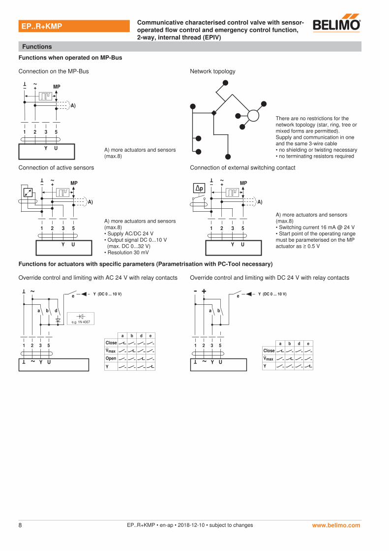
unctions when operated on MP- us
Connection on the MP-Bus Network topology
1 2 3 5
MP+
~
–
T
UY
A)
A) more actuators and sensors(max.8)
There are no restrictions for the network topology (star, ring, tree or mixed forms are permitted).Supply and communication in one and the same 3-wire cable
Connection of active sensors Connection of external switching contact
1 2 3 5
MP+
~
–
T
UY
A)
A) more actuators and sensors(max.8)
(max. DC 0...32 V)
1 2 3 5
MP+
~
–
T
UY
A)
p
A) more actuators and sensors(max.8)
must be parameterised on the MP
unctions for actuators with specific parameters (Parametrisation with PC-Tool necessary)
Override control and limiting with AC 24 V with relay contacts Override control and limiting with DC 24 V with relay contacts
T ~
a b d
U
T ~
Y
e
51 2 3
a b d e
Close
max
Open
Y
Y (DC 0 ... 10 V)
e.g. 1N 4007
+
a b
U
T ~
Y
e
51 2 3 a b d e
Close
max
Y
Y (DC 0 ... 10 V)
-
EP..R+KMP Communicative characterised control valve with sensor-operated flow control and emergency control function, 2-way, internal thread (EPIV)
unctions
ap 8 12-108

1
2 Cover, POP button
3 POP button
4 Scale for manual adjustment
5 Position for adjustment with tool
6 Tool socket
7 Disengagement button
LED displaysMeaning / function
8 yellow 9 green
Off On Operation OK / without fault
Off Flashing POP function active
On Off Fault
Off Off Not in operation
On On Adaptation procedure running
Flashing On Communication
8 Press button: Acknowledgment of addressing
9 Press button: Triggers angle of rotation adaption, followed by standard operation
StatusAddress
NCNO
0.9
0.5
0.1
TOOL
Power Adaption
POP
2
34
5
6
7
8 9
Emergency position (POP) setting
NCNO
0.9
0.5
0.1
NCNO
0.9
0.5
0.1
NCNO
0.9
0.5
0.1
A – AB
100%
A – AB
0%
A – AB
0 ... 100%
TOOL
TOOL
TOOL
NCNO
0.9
0.5
0.1POP
PC-Tool
ZTHTOOL
EP..R+KMP Communicative characterised control valve with sensor-operated flow control and emergency control function, 2-way, internal thread (EPIV)
perating controls and indicators
ap 8 12-10 9
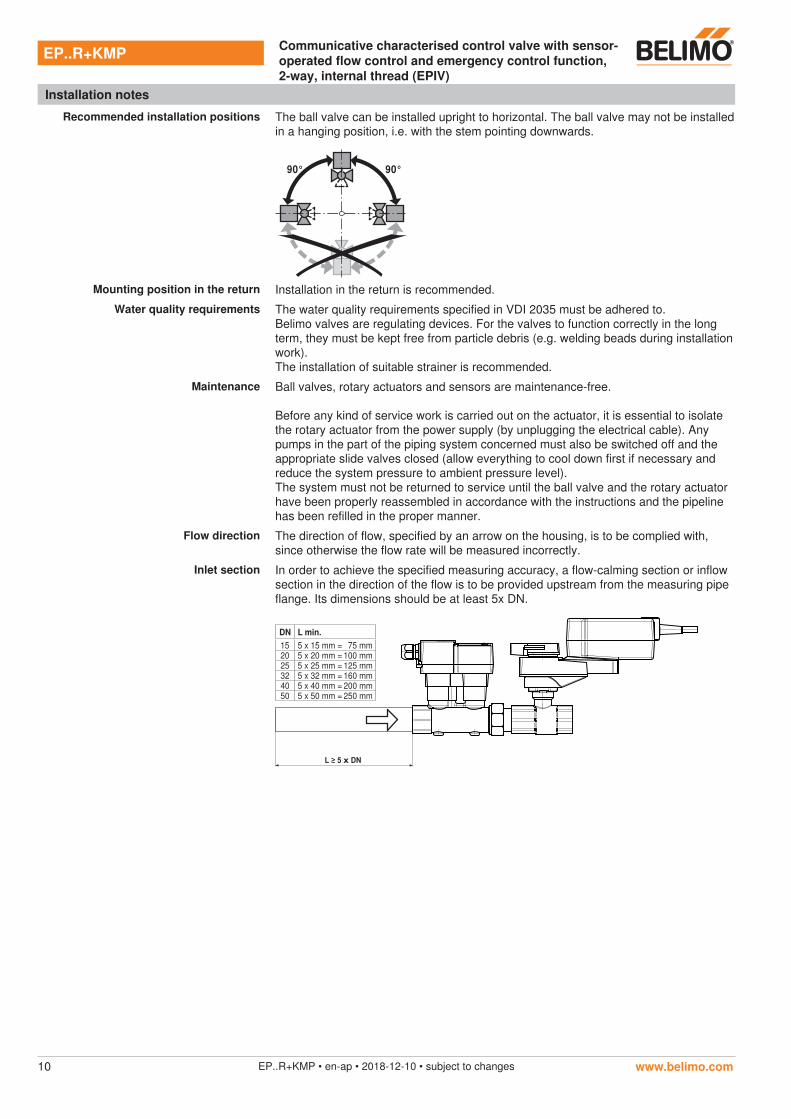
Recommended installation positions The ball valve can be installed upright to horizontal. The ball valve may not be installed in a hanging position, i.e. with the stem pointing downwards.
90° 90°
Mounting position in the return Installation in the return is recommended.
Water quality requirements The water quality requirements specified in VDI 2035 must be adhered to.Belimo valves are regulating devices. For the valves to function correctly in the long term, they must be kept free from particle debris (e.g. welding beads during installation work).The installation of suitable strainer is recommended.
Maintenance Ball valves, rotary actuators and sensors are maintenance-free.
Before any kind of service work is carried out on the actuator, it is essential to isolate the rotary actuator from the power supply (by unplugging the electrical cable). Any pumps in the part of the piping system concerned must also be switched off and the appropriate slide valves closed (allow everything to cool down first if necessary and reduce the system pressure to ambient pressure level).The system must not be returned to service until the ball valve and the rotary actuator have been properly reassembled in accordance with the instructions and the pipeline has been refilled in the proper manner.
low direction The direction of flow, specified by an arrow on the housing, is to be complied with, since otherwise the flow rate will be measured incorrectly.
Inlet section In order to achieve the specified measuring accuracy, a flow-calming section or inflow section in the direction of the flow is to be provided upstream from the measuring pipe flange. Its dimensions should be at least 5x DN.
L ≥ 5 x DN
DN L min.
15 5 x 15 mm = 75 mm20 5 x 20 mm = 100 mm25 5 x 25 mm = 125 mm32 5 x 32 mm = 160 mm40 5 x 40 mm = 200 mm50 5 x 50 mm = 250 mm
EP..R+KMP Communicative characterised control valve with sensor-operated flow control and emergency control function, 2-way, internal thread (EPIV)
Installation notes
ap 8 12-1010

General note3A calculation of the kvs value is not required.
If no hydraulic data are available, then the same valve DN can be selected as the heat exchanger nominal diameter.
General note3 The minimum required differential pressure (pressure drop through the valve) for
theoretical kvs value (see type overview) and the below-mentioned formula. The
differential pressures are compensated for automatically by the valve.
Formula
Δpmin = 100 xmax
kvs theor.
2 Δpmin: kPa
max: m3/h
kvs theor.: m3/h
Δpmin = 100 xmax
kvs theor.
2
= 100 x = 6 kPa2.07 m3/h
8.6 m3/h
2
EP025R+KMP
kvs theor. = 8.6 m /h
nom = 69 l/min
50% * 69 l/min = 34.5 l/min = 2.07 m /h
3
3
imensions Weight
imensional drawings
L1 L2BL3
Rp
min. Y
Hm
in. X
L
Type[ ]
Rp[”] [ mm] [ mm]
2[ mm]
3[ mm] [ mm]
H[ mm]
X[ mm]
Y[ mm]
Weight approx.[ kg]
EP0 R+KMP 15 1/2 331 192 128 13 98 143 195 77 1.5EP020R+KMP 20 3/4 348 211 123 14 98 145 195 77 1.8EP02 R+KMP 25 1 344 230 116 16 98 145 197 77 2.0EP032R+KMP 32 1 1/4 359 255 110 19 98 150 201 77 2.8EP0 0R+KMP 40 1 1/2 361 267 105 19 98 150 211 77 3.3EP0 0R+KMP 50 2 381 288 100 22 98 156 212 77 4.4
EP..R+KMP Communicative characterised control valve with sensor-operated flow control and emergency control function, 2-way, internal thread (EPIV)
General notes
ap 8 12-10 11
General notes for project planning
urther documentation
-N 50 2 381 288 100 22 98 156 212 77 4.4