technical data td02602011e edr-4000 distribution...
TRANSCRIPT
contentsDescription Page
Key Features, Functions and Benefits . . . . . . . . . . 2General Description . . . . . . . . . . . . . . . . . . . . . . . . 2Features . . . . . . . . . . . . . . . . . . . . . . . . . . . . . . . . . 3Protection and Control Functions . . . . . . . . . . . . . 4Monitoring and Metering . . . . . . . . . . . . . . . . . . . . 5Communication Software . . . . . . . . . . . . . . . . . . 10Standards, Certifications and Ratings . . . . . . . . . 11Standards . . . . . . . . . . . . . . . . . . . . . . . . . . . . . . 13Specifications . . . . . . . . . . . . . . . . . . . . . . . . . . . 15Ordering Information . . . . . . . . . . . . . . . . . . . . . . 18
Effective April 2010Technical Data TD02602011E
EDR-4000Distribution Protection Relay

2
Technical Data TD02602011EEffective April 2010
EDR-4000Distribution Protection Relay
EATon coRPoRATion www.eaton.com
Key Features, Functions and Benefits• Microprocessor-based protection with monitoring and control for
medium voltage main and feeder applications.
• Current, voltage, and frequency protection for electrical power distribution systems.
• Complete metering of voltage, currents, power, energy, mini-mum/maximum and demand functions.
• Complete metering, protection, and control in a single compact case to reduce panel space, wiring and costs.
• Integral test function reduces maintenance time and expense.
• Zone selective interlocking improves coordination and tripping time, and saves money compared to a traditional bus differential scheme.
• Programmable logic control functions for main-tie-main transfer schemes*.
• Reduce trouble shooting time and maintenance costs- Trip and event recording in non-volatile memory provides detailed informa-tion for analysis and system restoration. 6000 cycles of waveform capture aids in post fault analysis (viewable using Powerport-E software)
• Minimum replacement time- Removable terminal blocks ideal in industrial environments
• Front RS-232 port and Powerport-E software provides local com-puter access and user-friendly windows based interface for relay settings, configuration, and data retrieval.
• Breaker open/close from relay faceplate or remotely via commu-nications.
• Fast an easy troubleshooting, improved maintenance procedures and increased device security. Provides detailed traceability for system configuration changes
• Relays self-diagnostics and reporting improves uptime and trou-bleshooting.
• Breaker trip circuit monitoring improves the reliability of the breaker operation.
General DescriptionEaton’s EDR-4000 distribution protection relay is a multi-functional, microprocessor-based relay for feeder circuits of all voltage levels. It may be used as a primary protection on feeders, mains and tie circuit breaker applications; or as backup protection for transformers, high voltage lines and differential protection. The relay is most com-monly used on medium voltage switchgear applications
The EDR-4000 feeder protection relay provides complete current, voltage, and frequency protection and metering in a single, compact case. The relay has four current inputs rated for either 5 amperes or 1 ampere and four voltage inputs. Three of the voltage inputs are to be connected to the 3-phase power voltage for voltage protection and for metering. They can be connected in wye-ground or open delta configuration. The fourth voltage is for independent single-phase undervoltage/overvoltage protection, or ground protection for an ungrounded system.
The maintenance mode password protected soft key, can be used for arc flash mitigation to change to an alternate settings group, set to have instantaneous elements only. The multiple setting groups can also be changed, via communications or a digital input.
An integral keypad and display is provided for direct user program-ming and retrieval of data without the need of a computer. 14 pro-grammable LEDs provide quick indication of relay status.
A front port is provided for direct computer connection. An RS-485 communication port on the back is standard for local area network-ing using Modbus-RTU. An optional Ethernet port and protocols are available.
The EDR-4000 distribution protection relay includes program-mable logic functions*. Logic gates and timers may be defined and arranged for customized applications. Programmable logic control functions make the EDR-4000 relay ideally suited for main-tie-main and main 1/main 2 transfer schemes.
Flash memory is used for the programming and all settings are stored in nonvolatile memory. The relay allows for four prepro-grammed setting groups which can be activated through software, the display or a contact input.
The EDR-4000 distribution protection relay has mass memory for data storage and a real-time clock with 1 ms time resolution. The relay will log 300 sequence of event records, 20 detailed trip logs, minimum/maximum values, load profiles, breaker wear information and oscillography data.
The EDR-4000 has eight programmable binary inputs, 2 normally opened and 8 Form C heavy duty outputs and one form C signal alarm relay. It can be powered from 19 Vdc to 300 Vdc or 40 Vac to 250 Vac auxiliary power
* Future

3
Technical Data TD02602011EEffective April 2010
EDR-4000Distribution Protection Relay
EATon coRPoRATion www.eaton.com
FeaturesProtection Features
• Phase overcurrent elements:• Three instantaneous elements with timers ( 50P[1], 50P[2], and
50P[3])
• Three inverse time overcurrent elements (51P[1], 51P[2], and 51P[3])
• 11 standard curves
• Instantaneous or time delay reset
• 51P[2], and 51P[3] can be voltage restrained
• Ground overcurrent elements:• Two instantaneous measured elements with timers (50X[1],
and 50X[2])
• Two instantaneous calculated elements with timers (50R[1], and 50R[2])
• Two inverse time overcurrent measured elements (51X[1], and 51X[2])
• Two inverse time overcurrent calculated elements (51R[1], and 51R[2])
• 11 standard curves
• Instantaneous or time delay reset
• Breaker failure (50BF)
• Phase unbalance negative sequence overcurrent (46[1], 46[2])
• Phase voltage unbalance and sequence protection (47[1], 47[2])
• Main 3-phase under/over voltage (27M[1], 27M[2], 59M[1], 59M[2])
• Auxiliary single-phase under/over voltage (27A[1], 27A[2], 59A[1], 59A[2])
• Ground fault overvoltage relay (59N[1], 59N[2])
• Six frequency elements that can be assigned to: over frequency, under frequency, rate of change, or vector surge (81[1], 81[2], 81[3], 81[4], 81[5], 81[6])
• Apparent and displacement power factor (55A[1], 55A[2], 55D[1], 55D[2])
• Zone interlocking for bus protection (87B)
• Switch onto fault protection
• Cold load pickup
Metering Features
• Amperes: Positive, negative and zero sequence• Ampere demand• Volts: Positive, negative and zero sequence• Phase angles• Volt-amperes and VA demand• Watts and kW demand• kWh (forward, reverse, net)• Vars and kvar demand• kvarh (lead, leg and net)• Power factor• Frequency
• % THD V and I• Magnitude THD V and I• Minimum/maximum recording• Trending (load profile over time)*
Monitoring Features
• Trip coil monitor • Breaker wear primary and secondary (accumulated interrupted
current)• Oscillography (6000 cycles total)• Fault data logs (up to 20 events)• Sequence of events report (up to 300 events)• Clock (1 ms time stamping)
Control Functions
• Breaker open/close • Remote open/close• Programmable I/O• Programmable Logic*• Programmable LEDs• Multiple setting groups• Cold load pickup• CT supervision• VT supervision
Communication Features
• Local HMI• Password protected• Addressable• IRIG-B• Local communication port• Remote communication port:
• RS-232
• RS-485
• Protocols:• Modbus-RTU
• Modbus-TCP (Optional)
• Configuration software (Powerport-E)
* Future
4
Technical Data TD02602011EEffective April 2010
EDR-4000Distribution Protection Relay
EATon coRPoRATion www.eaton.com
Protection and Control FunctionsThe Eaton’s EDR-4000 distribution protection relay has been designed for maximum user flexibility and simplicity. The base relay includes all the standard current, voltage, and frequency protection, and metering functions.
Overcurrent Protection
The EDR-4000 distribution protection relay provides complete 3-phase and ground overcurrent protection. There are 8 independent ground overcurrent elements. The ground elements “X” use the independently measured ground (or neutral) current from a separate current-sensing input. The ground elements “R” uses a calculated 3Io residual current obtained from the sum of the 3-phase currents. This calculated current could be used for either the neutral or ground current in a 3-phase, 4-wire system. Each of the phase and ground overcurrent elements can be selected to operate based on funda-mental or RMS current.
Voltage Restrained Overcurrent
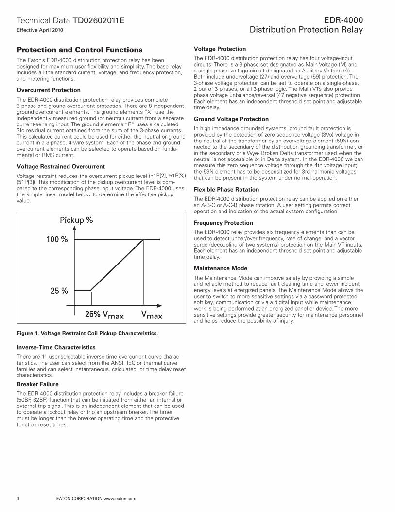
Voltage restraint reduces the overcurrent pickup level (51P[2], 51P[3]) (51P[3]). This modification of the pickup overcurrent level is com-pared to the corresponding phase input voltage. The EDR-4000 uses the simple linear model below to determine the effective pickup value.
Figure 1. Voltage Restraint Coil Pickup Characteristics.
Inverse-Time Characteristics
There are 11 user-selectable inverse-time overcurrent curve charac-teristics. The user can select from the ANSI, IEC or thermal curve families and can select instantaneous, calculated, or time delay reset characteristics.
Breaker Failure
The EDR-4000 distribution protection relay includes a breaker failure (50BF, 62BF) function that can be initiated from either an internal or external trip signal. This is an independent element that can be used to operate a lockout relay or trip an upstream breaker. The timer must be longer than the breaker operating time and the protective function reset times.
Voltage Protection
The EDR-4000 distribution protection relay has four voltage-input circuits. There is a 3-phase set designated as Main Voltage (M) and a single-phase voltage circuit designated as Auxiliary Voltage (A). Both include undervoltage (27) and overvoltage (59) protection. The 3-phase voltage protection can be set to operate on a single-phase, 2 out of 3 phases, or all 3-phase logic. The Main VTs also provide phase voltage unbalance/reversal (47 negative sequence) protection. Each element has an independent threshold set point and adjustable time delay.
Ground Voltage Protection
In high impedance grounded systems, ground fault protection is provided by the detection of zero sequence voltage (3Vo) voltage in the neutral of the transformer by an overvoltage element (59N) con-nected to the secondary of the distribution grounding transformer, or in the secondary of a Wye- Broken Delta transformer used when the neutral is not accessible or in Delta system. In the EDR-4000 we can measure this zero sequence voltage through the 4th voltage input; the 59N element has to be desensitized for 3rd harmonic voltages that can be present in the system under normal operation.
Flexible Phase Rotation
The EDR-4000 distribution protection relay can be applied on either an A-B-C or A-C-B phase rotation. A user setting permits correct operation and indication of the actual system configuration.
Frequency Protection
The EDR-4000 relay provides six frequency elements than can be used to detect under/over frequency, rate of change, and a vector surge (decoupling of two systems) protection on the Main VT inputs. Each element has an independent threshold set point and adjustable time delay.
Maintenance Mode
The Maintenance Mode can improve safety by providing a simple and reliable method to reduce fault clearing time and lower incident energy levels at energized panels. The Maintenance Mode allows the user to switch to more sensitive settings via a password protected soft key, communication or via a digital Input while maintenance work is being performed at an energized panel or device. The more sensitive settings provide greater security for maintenance personnel and helps reduce the possibility of injury.
5
Technical Data TD02602011EEffective April 2010
EDR-4000Distribution Protection Relay
EATon coRPoRATion www.eaton.com
Monitoring and MeteringSequence of Events Records
The EDR-4000 protection relay records a maximum of 300 events associated with the relay. An event is classified as a change of state as detected by the relay. These include relay pickups, dropouts, trips, contact closure, alarms, setting changes and self-diagnostic failures. Each event is date and time stamped to a 1 ms resolution. The events are stored in a FIFO log in chronological order.
Trip Log
The EDR-4000 protection relay will store a maximum of 20 trip records in a FIFO trip log. Each trip record will be date and time stamped to a 1 ms resolution. The trip log record will include infor-mation on the type of fault, protection elements that operated, fault location and currents and voltages at the time of the fault.
Waveform Capture
The EDR-4000 feeder protection relay provides oscillography-record-ing capabilities. The relay will record all measured signals along with the binary signals of pickup, trip, logic and contact closures. The EDR-4000 relay can record up to 6000 cycles of data. The number of records is proportional to the size of each record; the maximum size per record is 600 cycles. The waveform capture is initiated by up to eight different triggers; it can also be generated manually through the display or via communications.
Integral User Interface
The front panel user interface has a 128 x 64 pixel LCD display with background illumination for wide angle viewing in all light conditions. 17 programmable LEDs provide quick and easy visual display of power on, mode of operation, alarm and trip indication. Soft keys are provided for operation mode selection, scrolling through data and settings. In addition, the relay settings and test functions are pass-word protected.
Programmable I/O
The EDR-4000 distribution protection relay provides heavy-duty, trip-rated, two normally open and eight Form C contacts. Two iso-lated inputs can be used for monitoring the trip circuit. One Form C contact is dedicated to the relay failure alarm function and is operated in a normally energized (failsafe) mode. There are eight user-configurable discrete inputs that accept a wet contact and can operate through a wide range of power. Each input and output is user-programmable for maximum application flexibility.
Programmable Logic*
The EDR-4000 distribution protection relay provides logic gates and timers that the user can customize for special or unique applica-tions. Each gate can be assigned a logic function of either AND, OR, NAND or NOR. Each gate can have a maximum of four input signals and each input signal can be required to be a NOT. Input signals can be external inputs received via the binary inputs or internal values associated with the protection, alarm or metering set points. Each gate has a unique output assignment and designation that can be used as the input to another gate. There are 24 independent timers that have adjustable pickup and dropout delay settings.
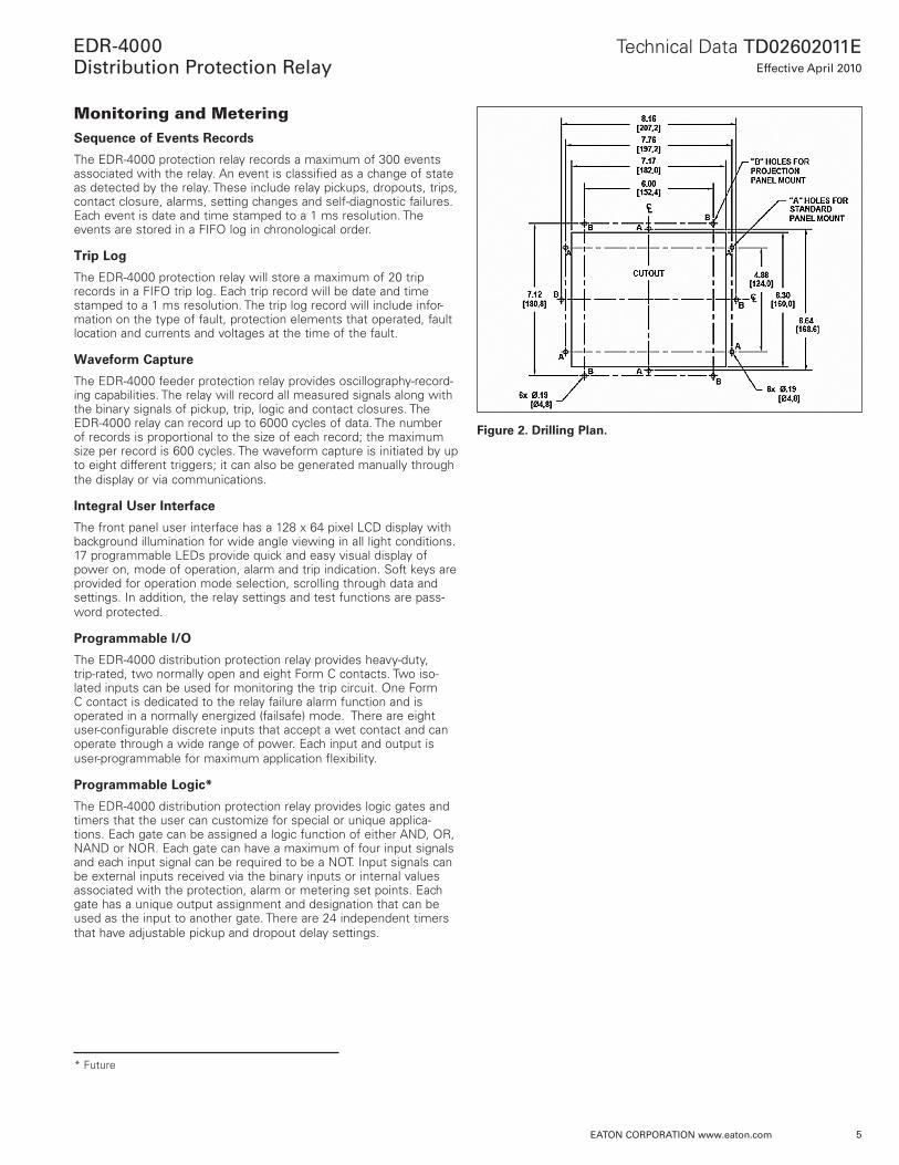
Figure 2. Drilling Plan.
* Future
6
Technical Data TD02602011EEffective April 2010
EDR-4000Distribution Protection Relay
EATon coRPoRATion www.eaton.com
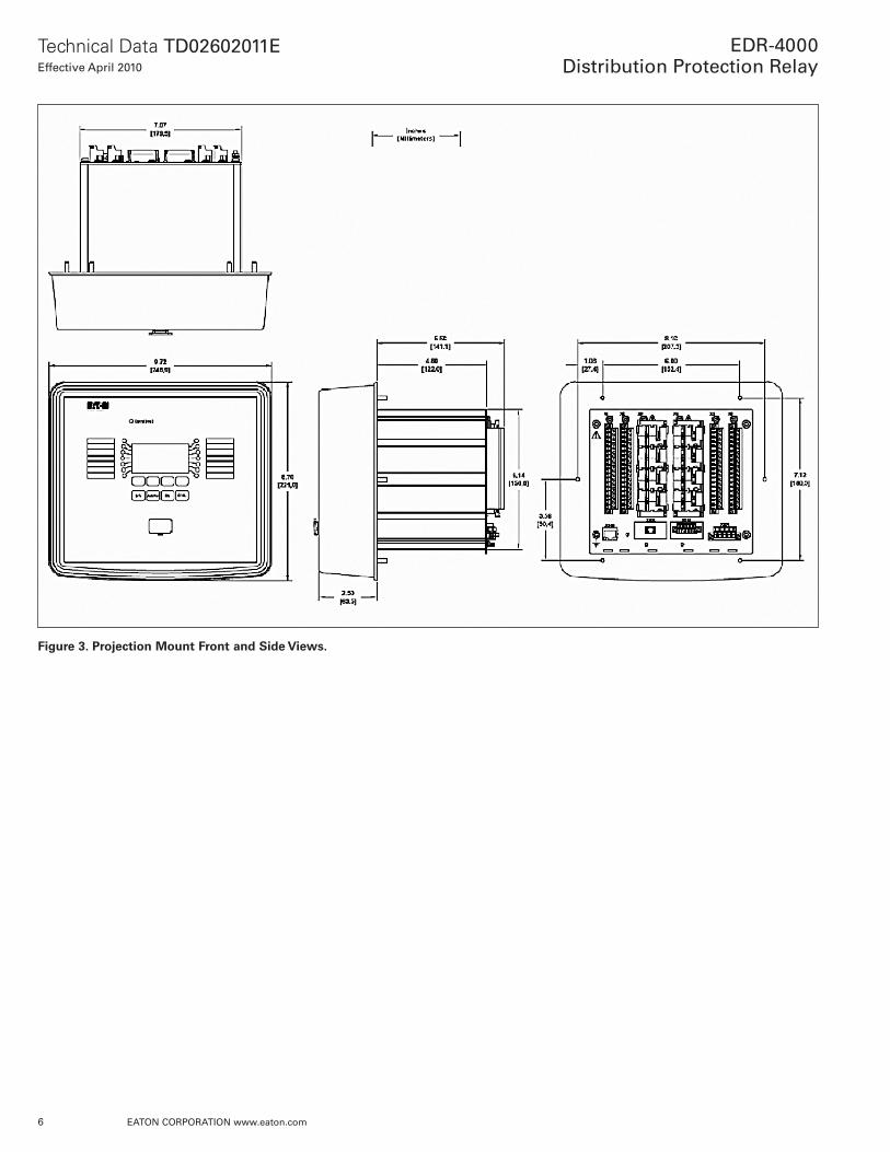
Figure 3. Projection Mount Front and Side Views.

7
Technical Data TD02602011EEffective April 2010
EDR-4000Distribution Protection Relay
EATon coRPoRATion www.eaton.com
Figure 4. Standard Mount Front and Side Views.
8
Technical Data TD02602011EEffective April 2010
EDR-4000Distribution Protection Relay
EATon coRPoRATion www.eaton.com
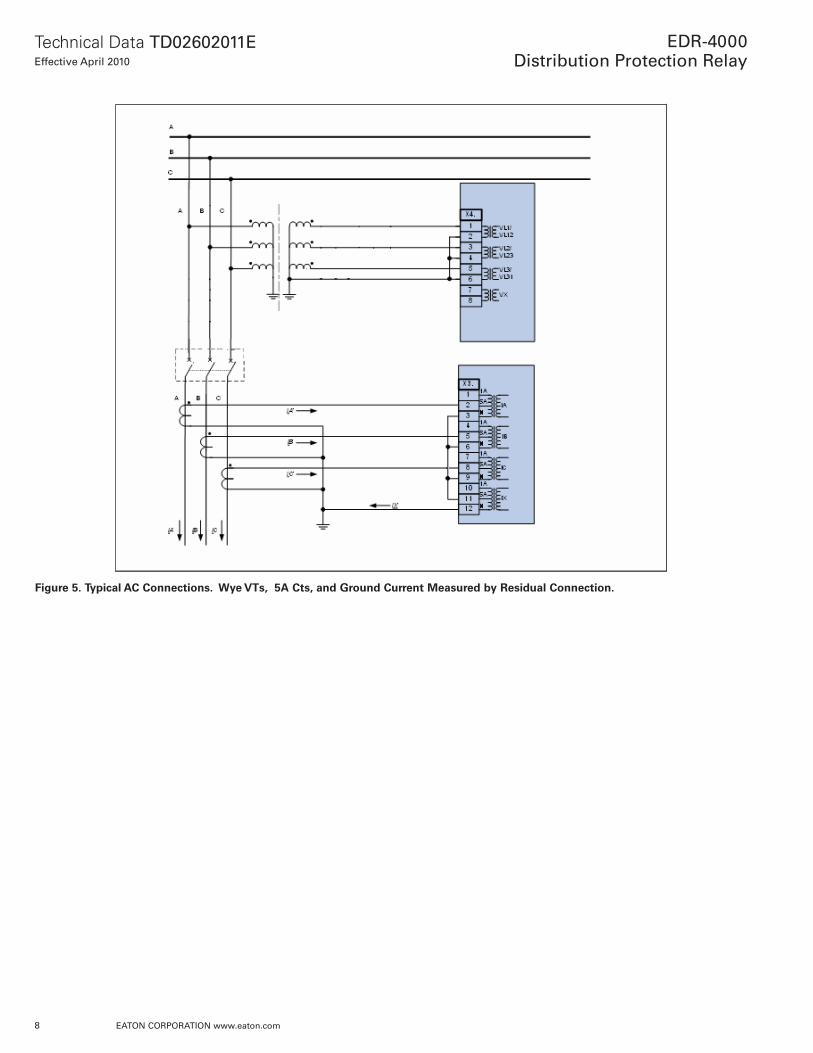
Figure 5. Typical AC Connections. Wye VTs, 5A Cts, and Ground Current Measured by Residual Connection.

9
Technical Data TD02602011EEffective April 2010
EDR-4000Distribution Protection Relay
EATon coRPoRATion www.eaton.com
Figure 6. Typical One-Line Diagram.
Figure 7. Typical Control Diagram.

10
Technical Data TD02602011EEffective April 2010
EDR-4000Distribution Protection Relay
EATon coRPoRATion www.eaton.com
Communication SoftwareEaton provides two types of communication software. The first is PowerPort-E. It runs on a PC or laptop for easy access to a single relay to change set points or configuration and to view metered values and stored data. PowerPort-E is free and can be downloaded from the Eaton Web site at the following URL: http://www.EatonElectrical.com/pr
The second package is Power Xpert Software. Power Xpert Software is a power management software package that is designed for continu-ous, remote monitoring of many devices. It provides additional functions such as billing, trending and graphics. Contact your local Eaton rep-resentative for more information on Power Xpert software.
Figure 8. Powerport-E - EDR-4000 Device Planning.

11
Technical Data TD02602011EEffective April 2010
EDR-4000Distribution Protection Relay
EATon coRPoRATion www.eaton.com
Standards, Certifications and RatingsClimatic Environmental Conditions
Storage Temperature: -30°C to +70°C (-22°F to 158°F)
Operating Temperature: -20°C to +60°C (-4°F to 140°F)
Permissible Humidity at Ann. Average: <75% rel. (on 56d up to 95% rel.)
Permissible Installation Altitude: <2,000 m (6,561.67 ft) above sea level.If 4,000 m (13,123.35 ft) altitude applies, a changed classification of the operating and test voltages may be necessary.
Degree of Protection EN 60529
HMI Front Panel with Seal: IP54
Rear Side Terminals: IP20
Routine Test
Insulation Test Acc. to IEC60255-5: All tests to be carried out against ground and other input and output circuits.
Aux. Voltage Supply, Digital Inputs, Current Measuring Inputs, Signal Relay Outputs:
2.5 kV (eff.) / 50 Hz
Voltage Measuring Inputs: 3.0 kV (eff.) / 50 Hz
All Wire-Bound Communication Interfaces:
1.5 kV DC
Housing
Housing B2: Height / Width 183 mm (7.205 in.)/ 212.7 mm (8.374 in.)
Housing Depth (Incl. Terminals): 208 mm (8.189 in.)
Material, Housing: Aluminum extruded section
Material, Front Panel: Aluminum/Foil front
Mounting Position: Horizontal (±45° around the X-axis must be permitted)
Weight: Approx. 4.2 kg (9.259 lb)
Current and Ground Current Measurement
Nominal Currents: 1 A / 5 A
Max. Measuring Range: Up to 40 x In (phase currents)Up to 25 x In (ground current standard)Up to 2.5 x In (ground current sensitive)
Continuous Loading Capacity: 4 x In/continuously
Overcurrent Proof: 30 x In / 10 s100 x In / 1 s250 x In / 10 ms (1 half-wave)
Power Consumption: Phase current inputs At In = 1A S = 0.15 mVAAt In = 5A S = 0.15 mVA
Ground current inputAt In = 1A S = 0.35 mVAAt In = 5A S = 0.35 mVA
Frequency Range: 50 Hz / 60 Hz ±10%
Terminals: Screw-type terminals with integrated short-circuiters (contacts)
Connection Cross Sections: 1 x or 2 x 2.5 mm² (2 x AWG 14) with wire end ferrule.1 x or 2 x 4.0 mm² (2 x AWG 12) with ring cable sleeve or cable sleeve. 1 x or 2 x 6 mm² (2 x AWG 10) with ring cable sleeve or cable sleeve.
The current measuring board´s terminal blocks may be used as with two (double) conductors AWG 10,12,14 otherwise with single conductors only.
Plug-in Connector with Integrated Short-Circuiter (Conventional Current Inputs)
Nominal Current: 1 A and 5 A
Continuous Loading Capacity: 4 x In / continuously
Overcurrent Withstand: 30 x In / 10 s100 x In / 1 s250 x In / 10 ms (1 half-wave)
Screws: M4, captive type acc. to VDEW
Connection Cross Sections: 1 x or 2 x 2.5 mm² (2 x AWG 14) with wire end ferrule.1 x or 2 x 4.0 mm² (2 x AWG 12) with ring cable sleeve or cable sleeve.1 x or 2 x 6mm² (2 x AWG 10) with ring cable sleeve or cable sleeve.
The current measuring board´s terminal blocks may be used as with 2 (double) conductors AWG 10,12,14 otherwise with single conductors only.
12
Technical Data TD02602011EEffective April 2010
EDR-4000Distribution Protection Relay
EATon coRPoRATion www.eaton.com
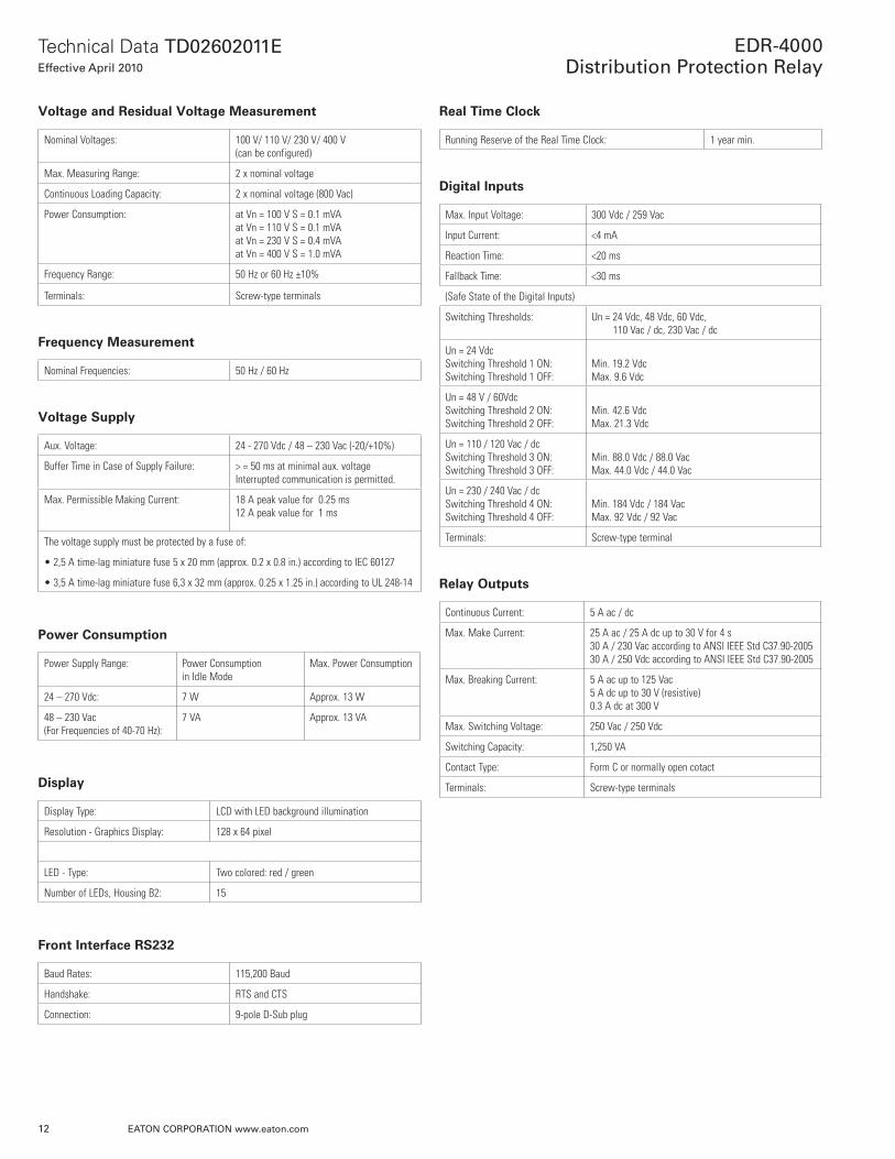
Voltage and Residual Voltage Measurement
Nominal Voltages: 100 V/ 110 V/ 230 V/ 400 V(can be configured)
Max. Measuring Range: 2 x nominal voltage
Continuous Loading Capacity: 2 x nominal voltage (800 Vac)
Power Consumption: at Vn = 100 V S = 0.1 mVAat Vn = 110 V S = 0.1 mVAat Vn = 230 V S = 0.4 mVAat Vn = 400 V S = 1.0 mVA
Frequency Range: 50 Hz or 60 Hz ±10%
Terminals: Screw-type terminals
Frequency Measurement
Nominal Frequencies: 50 Hz / 60 Hz
Voltage Supply
Aux. Voltage: 24 - 270 Vdc / 48 – 230 Vac (-20/+10%)
Buffer Time in Case of Supply Failure: > = 50 ms at minimal aux. voltageInterrupted communication is permitted.
Max. Permissible Making Current: 18 A peak value for 0.25 ms12 A peak value for 1 ms
The voltage supply must be protected by a fuse of:
• 2,5 A time-lag miniature fuse 5 x 20 mm (approx. 0.2 x 0.8 in.) according to IEC 60127
• 3,5 A time-lag miniature fuse 6,3 x 32 mm (approx. 0.25 x 1.25 in.) according to UL 248-14
Power Consumption
Power Supply Range: Power Consumptionin Idle Mode
Max. Power Consumption
24 – 270 Vdc: 7 W Approx. 13 W
48 – 230 Vac (For Frequencies of 40-70 Hz):
7 VA Approx. 13 VA
Display
Display Type: LCD with LED background illumination
Resolution - Graphics Display: 128 x 64 pixel
LED - Type: Two colored: red / green
Number of LEDs, Housing B2: 15
Front Interface RS232
Baud Rates: 115,200 Baud
Handshake: RTS and CTS
Connection: 9-pole D-Sub plug
Real Time Clock
Running Reserve of the Real Time Clock: 1 year min.
Digital Inputs
Max. Input Voltage: 300 Vdc / 259 Vac
Input Current: <4 mA
Reaction Time: <20 ms
Fallback Time: <30 ms
(Safe State of the Digital Inputs)
Switching Thresholds: Un = 24 Vdc, 48 Vdc, 60 Vdc, 110 Vac / dc, 230 Vac / dc
Un = 24 VdcSwitching Threshold 1 ON:Switching Threshold 1 OFF:
Min. 19.2 VdcMax. 9.6 Vdc
Un = 48 V / 60VdcSwitching Threshold 2 ON:Switching Threshold 2 OFF:
Min. 42.6 VdcMax. 21.3 Vdc
Un = 110 / 120 Vac / dcSwitching Threshold 3 ON:Switching Threshold 3 OFF:
Min. 88.0 Vdc / 88.0 VacMax. 44.0 Vdc / 44.0 Vac
Un = 230 / 240 Vac / dcSwitching Threshold 4 ON:Switching Threshold 4 OFF:
Min. 184 Vdc / 184 VacMax. 92 Vdc / 92 Vac
Terminals: Screw-type terminal
Relay Outputs
Continuous Current: 5 A ac / dc
Max. Make Current: 25 A ac / 25 A dc up to 30 V for 4 s 30 A / 230 Vac according to ANSI IEEE Std C37.90-200530 A / 250 Vdc according to ANSI IEEE Std C37.90-2005
Max. Breaking Current: 5 A ac up to 125 Vac 5 A dc up to 30 V (resistive)0.3 A dc at 300 V
Max. Switching Voltage: 250 Vac / 250 Vdc
Switching Capacity: 1,250 VA
Contact Type: Form C or normally open cotact
Terminals: Screw-type terminals
13
Technical Data TD02602011EEffective April 2010
EDR-4000Distribution Protection Relay
EATon coRPoRATion www.eaton.com
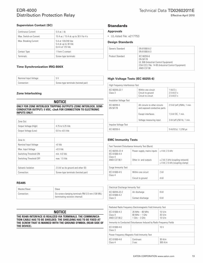
Supervision Contact (SC)
Continuous Current: 5 A ac / dc
Max. Switch-on Current: 15 A ac / 15 A dc up to 30 V for 4 s
Max. Breaking Current: 5 A at 120/240 Vac 5 A dc up to 30 Vdc 0,4 A at 125 Vdc
Contact Type: 1 Form C contact
Terminals: Screw-type terminals
Time Synchronization IRIG-B00X
Nominal Input Voltage: 5 V
Connection: Screw-type terminals (twisted pair)
Zone Interlocking
noticeonly for Zone interlock tripping outputs (Zone interlock, semi-conductor output): 5 Vdc, <2mA for connection to electronic inputs only.
Zone Out:
Output Voltage (High) 4.75 to 5.25 Vdc
Output Voltage (Low) 0.0 to +0.5 Vdc
Zone In:
Nominal Input Voltage +5 Vdc
Max. Input Voltage +5.5 Vdc
Switching Threshold ON min. 4.0 Vdc
Switching Threshold OFF max. 1.5 Vdc
Galvanic Isolation 2.5 kV ac (to ground and other IO)
Connection: Screw-type terminals (twisted pair)
RS485
Master/Slave: Slave
Connection: Six screw-clamping terminals RM 3.5 mm (138 MIL)(terminating resistors internal)
noticethe rs485 interfAce is reAliZed ViA terminAls. the communicA-tion cAble hAs to be shielded. the shielding hAs to be fixed At the screw thAt is mArked with the ground symbol (reAr side of the deVice).
StandardsApprovals
• UL-listed file: e217753
Design Standards
Generic Standard EN 61000-6-2EN 61000-6-3
Product Standard IEC 60255-6EN 50178 UL 508 (Industrial Control Equipment)CSA C22.2 No. 14-95 (Industrial Control Equipment)ANSI C37.90
High Voltage Tests (IEC 60255-6)
High Frequency Interference Test
IEC 60255-22-1Class 3
Within one circuitCircuit to groundCircuit to circuit
1 kV/2 s2.5 kV/2 s2.5 kV/2 s
Insulation Voltage Test
IEC 60255-5EN 50178
All circuits to other circuits and exposed conductive parts. Except interfaces.
Voltage measuring input.
2.5 kV (eff.)/50Hz, 1 min.
1,5 kV DC, 1 min.
3 kV (eff.)/50 Hz, 1 min.
Impulse Voltage Test
IEC 60255-5 5 kV/0.5J, 1.2/50 µs
EMC Immunity Tests
Fast Transient Disturbance Immunity Test (Burst)
IEC 60255-22-4IEC 61000-4-4Class 4ANSI C37.90.1
Power supply, mains inputs
Other in- and outputs
± 4 kV, 2.5 kHz
± 2 kV, 5 kHz (coupling network)± 4 kV, 2.5 kHz (coupling clamp)
Surge Immunity Test
IEC 61000-4-5Class 4
Within one circuit
Circuit to ground
2 kV
4 kV
Electrical Discharge Immunity Test
IEC 60255-22-2IEC 61000-4-2Class 3
Air discharge
Contact discharge
8 kV
6 kV
Radiated Radio Frequency Electromagnetic Field Immunity Test
IEC 61000-4-3Class XANSI C37.90.2
26 MHz – 80 MHz80 MHz – 1 GHz1 GHz – 3 GHz
10 V/m35 V/m10 V/m
Immunity to Conducted Disturbances Induced by Radio Frequency Fields
IEC 61000-4-6Class 3
10 V
Power Frequency Magnetic Field Immunity Test
IEC 61000-4-8Class 4
Continues3 sec
30 A/m300 A/m

14
Technical Data TD02602011EEffective April 2010
EDR-4000Distribution Protection Relay
EATon coRPoRATion www.eaton.com
Mechanical Tests
Test Fc: Vibration Response Test
IEC 60068-2-6IEC 60255-21-1Class 1
(10 Hz – 59 Hz) Displacement(59Hz – 150Hz) AccelerationNumber of cycles in each axis
0.0014 in. (0.035 mm)0.5 gn1
Test Fc: Vibration Endurance Test
IEC 60068-2-6IEC 60255-21-1Class 1
(10 Hz – 150 Hz)Acceleration
Number of cycles in each axis
1.0 gn
20
Test Ea: Shock Test
IEC 60068-2-27IEC 60255-21-2Class 1
Shock response test 5 gn, 11 ms, 3 impulses in each direction
Shock resistance test 15 gn, 11 ms, 3 impulses in each direction
Test Eb: Shock Endurance Test
IEC 60068-2-29IEC 60255-21-2Class 1
Shock endurance test 10 gn, 16 ms, 1,000 impulses in each direction
Test Fe: Earthquake Test
IEC 60068-3-3KTA 3503IEC 60255-21-3
Single axis earthquake vibration test
3 – 7 Hz: Horizontal 0.394 in. (10 mm), 1 cycle each axis
Class 2 7 – 35 Hz Horizontal: 2 gn, 1 cycle each axis
EMC Emission Tests
Radio Interference Suppression Test
IEC/CISPR11 Limit value class B
Radio Interference Radiation Test
IEC/CISPR11 Limit value class B
Environmental Tests
Classification:
IEC 60068-1 ClimaticClassification
0/055/56
IEC 60721-3-1 Classification of ambient conditions (Storage)
1K5/1B1/1C1L/1S1/1M2but min. -25°C (-13°F)
IEC 60721-3-2 Classification of ambient conditions (Transportation)
2K3/2B1/2C1/2S1/2M2
IEC 60721-3-3 Classification of ambient conditions (Stationary use at weather protected locations)
3K6/3B1/3C1/3S1/3M2 but min. 0°C (32°F) and 3K8H for 2 h
Test Ad: Cold
IEC 60068-2-1 TemperatureTest duration
-20°C (-4°F)16 h
Test Bd: Dry Heat
IEC 60068-2-2 TemperatureRelative humidityTest duration
55°C (131°F)<50%72 h
Test Cab: Damp Heat (Steady State)
IEC 60068-2-78 TemperatureRelative humidityTest duration
40°C (104°F)93%56 d
Test Db: Damp Heat (Cyclic)
IEC 60068-2-30 TemperatureRelative humidityCycles (12 + 12-hour)
55°C (131°F)95%2

15
Technical Data TD02602011EEffective April 2010
EDR-4000Distribution Protection Relay
EATon coRPoRATion www.eaton.com
SpecificationsSpecifications of the Real Time Clock
Resolution: 1 ms
Tolerance: <1 minute / month (+20°C [68°F])
Specifications of the Measured Value Acquisition
Phase and Ground current Measuring
Max. Measuring Range: Up to 40 x In (phase currents)Up to 25 x In (ground current standard)
Frequency Range: 50 Hz / 60 Hz ± 10%
Accuracy: Class 0.5
Amplitude Error if I < 1 In: ±0.5% of the rated value
Amplitude Error if I > In: ±0.5% of the measured value
Amplitude Error if I > 2 In: ±1.0% of the measured value
Resolution: 0.01 A
Harmonics: Up to 20% 3rd harmonic ±1%Up to 20% 5th harmonic ±1%
Frequency Influence: <±2% / Hz in the range of ±5 Hz of the parametrized nominal frequency
Temperature Influence: <±1% within the range of 0°C to +60°C (+32°F to +140°F)
Phase-to-ground and Residual Voltage Measurement
Nominal Voltage (Vn): 100 V / 110 V / 230 V / 400 V (configurable)
Max Measuring Range: 2 x nominal value (Vn)
Frequency Range: 50 Hz or 60 Hz ±10%
Precision: Class 0,5
Amplitude Error for V<Vn: ±0.5% (of the nominal value)
Amplitude Error for V>Vn: ±0.5% (of the nominal value)
Resolution: 0.1 V
Harmonics: Up to 20% 3rd harmonic ±1%, up to 20% 5th harmonic ±1%
Frequency Influence: < ±2% / Hz in the range of ±5 Hz of the con-figured nominal frequency
Temperature Influence: <±1% within the range of 0°C up to +55°C
Frequency Measurement
Nominal Frequency: 50 Hz / 60 Hz
Precision: ±0.05% of fn within the range of 40-70 Hz
Voltage Dependency: Frequency acquisition of 5 V – 800 V
Protection Elements Tolerances
noticethe tripping delAy relAtes to the time between AlArm And trip. the AccurAcy of the operAting time relAtes to the time between when the meAsured VAlue hAs exceeded the threshold until the protection element is picked-up.
overcurrent protection elements: 50p[x], 51p[x] Accuracy
Pickup ±1.5% of the setting value resp. 1% x In.
Dropout Ratio 97% or 0.5% x In
t DEFT±1% resp. ±10 ms
Operating Time Starting from I Higher than 1.1 x I>
<35 ms
Disengaging Time <45 ms
t-Multiplier ±5%IEC NINVIEC VINVIEC EINVIEC LINVANSI MINVANSI VINVANSI EINVFlatItI2tI4t
Reset Mode ±1% resp. ±10 msIEC NINVIEC VINVIEC EINVIEC LINV
5%ANSI MINVANSI VINVANSI EINVFlatItI2tI4t

16
Technical Data TD02602011EEffective April 2010
EDR-4000Distribution Protection Relay
EATon coRPoRATion www.eaton.com
Voltage restraint 51V[x] Accuracy
Pickup ±1.5% of the setting value resp. 1% x In.
Dropout Ratio 97% or 0.5% x In
Operating TimeStarting from I Higher than 1.1 x I>
<35 ms
Disengaging Time <45 ms
t-Multiplier ±5%IEC NINVIEC VINVIEC EINVIEC LINVANSI MINVANSI VINVANSI EINVFlatItI2tI4t
Reset Mode ±1% resp. ±10 msIEC NINVIEC VINVIEC EINVIEC LINV
5%ANSI MINVANSI VINVANSI EINVFlatItI2tI4t
ground current elements: 50x[x], 50r[x], 51x[x], 51r[x] Accuracy
Pickup ±1.5% of the setting valueResp. 1% x In
Dropout Ratio 97% or 0.5% x In
t DEFT ±1% resp. ±10 ms
Operating TimeStarting from IE higher than 1.1 x IE>
<35 ms
Disengaging Time <45 ms
t-Multiplier ±5%IEC NINVIEC VINVIEC EINVIEC LINVANSI MINVANSI VINVANSI EINVFlatItI2tI4t
Reset Mode ±1% resp. ±10 msIEC characteristicsIEC NINVIEC VINVIEC EINVIEC LINV
5%Reset curves if ANSI characteristicsANSI MINVANSI VINVANSI EINVFlatItI2tI4t
phase under- and phase overvoltage 27m[x]/59m[x] Accuracy
Pickup ±1.5% of the setting valueResp. 1% x Vn
Dropout Ratio 97% or 0.5% x Vn
t DEFT±1% resp. ±10 ms
Operating TimeStarting from V Higher/Lower than 1.1 x V> or V<
<35 ms
Disengaging Time <45 ms
Aux. under- and phase overvoltage and neutral overvoltage 27A[x]/59A[x]/59n[x] Accuracy
Pickup ±1.5% of the setting valueResp. 1% x Vn
Dropout Ratio 97% or 0.5% x Vn
t DEFT±1% resp. ±10 ms
Operating TimeStarting from VG or VX Higher than 1.1 x VG> or VX>
<35 ms
Disengaging Time <45 ms

17
Technical Data TD02602011EEffective April 2010
EDR-4000Distribution Protection Relay
EATon coRPoRATion www.eaton.com
current unbalance: 46[x] Accuracy
Threshold ±2% of the setting value resp.1% In
I2/I1 ³ 0.1 x In 97% or 0.5% x In
t DEFT±1% resp. ±10 ms
Operating Time Starting from I2/I1 ³ 1.1 x In
<60 ms
Release Time <40 ms
Voltage unbalance: 47[x] Accuracy
Threshold ±2% of the setting value resp.1% Vn
V2/V1 ³ 0.1 x Vn 97% or 0.5% x Vn
t DEFT±1% resp. ±10 ms
Operating TimeStarting from V2/V1 ³ 1.1 x Vn
<60 ms
Release Time <40 ms
frequency protection 81o[x] Accuracy
Threshold 10 mHz at fn
Dropout ratio 99.95% or 0.05% x fn
t ±1% resp. ±10 ms
Operating Time Starting from f Higher than f>+0.02 Hz
40-50Hz <60 ms50-70Hz <50 ms
Release Time 40-50Hz <85 ms50-70Hz <75 ms
frequency protection 81u[x] Accuracy
Threshold 10 mHz at fn
t ±1% resp. ±10 ms
Dropout Ratio 100.05% or 0.05% x fn
Operating Time Starting from f Lower than f<-0.02 Hz
40-50Hz <60 ms50-70Hz <50 ms
Release Time 40-50Hz <85 ms50-70Hz <75 ms
V Block f ±1.5% of the setting value resp. 1% x Un
Dropout Ratio 103% or 0.5% x Un
rate of change of frequency df/dt Accuracy
Treshold 100 mHz per Second
t ±1% resp. ±10 ms
Operating Time <40 ms
Release Time <40 ms
rate of change of frequency df/dt Accuracy
Threshold 100 mHz per Second
t ±1% resp. ±10 ms
Operating Time <40 ms
Release Time <40 ms
Vector surge 78V Accuracy
Threshold ±0,5° [1-30°] at Vn and fn
Operating Time <40 ms
pf-55d/pf-55A - power factor Accuracy
Threshold ± 0.01 (absolute)
Operating Time <120 ms
sotf – switch onto fault Accuracy
Operating Time <35 ms
I< ±1.5% of the setting value resp.1% x In
t-enable ±1% resp. ±10 ms
clpu – cold load pickup Accuracy
Operating Time <35 ms
t-Load OFF ±1% resp. ±10 ms
t-Max Block ±1% resp. ±10 ms
I< ±1.5% of the setting value resp.1% x In
breaker failure protection 50bf Accuracy
I-BF> ±1.5% of the setting value resp.1% x In
Dropout Ratio
t-BF ±1% resp. ±10 ms
Operating TimeStarting from I Higher than 1.3 x I-BF>
<40 ms
Disengaging Time <40 ms
trip circuit monitoring tcm Accuracy
t-TCM ±1% resp. ±10 ms
lop - loss of potential Accuracy
t-Pickup ±1% resp. ±10 ms
current transformer supervision cts Accuracy
I ±2% of the setting value resp. 1.5% In
Dropout Ratio 94%
Pickup Delay ±1% resp. ± 10 ms

18
Technical Data TD02602011EEffective April 2010
EDR-4000Distribution Protection Relay
EATon coRPoRATion www.eaton.com
Ordering InformationSample Catalog Number
The catalog number identification chart defines the electrical char-acteristics and operation features included in the EDR-4000. For example, if the catalog number were EDR-4000A0BA1, the device would have the following:
EDR-4000
(A) - Eight Digital Inputs, Nine Output Relays
(0) - 5A/1A phase and ground CTs, Power Supply Range: 19-300 Vdc, 40-250 Vac
(B) - Modbus-RTU (RS-485)
(A) - Without Conformal Coating
(1) - Projection Panel Mount
Table 1. Catalog Ordering Information for EDR-4000 Eaton Distribution Protection Relay
edr-4000 eaton distribution relay removable terminals
edr-4000 A 0 b A 1
Choose from the following options.
hardware option 1
8 DI, 11 Outputs, Removable Terminals, Zone Interlocking, A
8 DI, 11 Outputs, Removable Terminals, Zone Interlocking, and large display* B
hardware option 2
Phase Current 5A/1A, Ground Current 5A/1A, Power Supply Range: 19-300 Vdc, 40-250 Vac 0 (Zero)
Phase Current 5A/1A Sensitive Ground Current, 0.5A/0.1A, Power Supply Range: 19-300 Vdc, 40-250 Vac* 1
communication options
Modbus-RTU (RS-485) B
Modbus-RTU + Modbus-TCP I
conformal coating options
None A
Conformal Coated Circuit Boards B
mounting options
Standard Mount 0 (Zero)
Projection Panel Mount 1
*Consult factory for the availability of sensitive ground, and large display.

19
Technical Data TD02602011EEffective April 2010
EDR-4000Distribution Protection Relay
EATon coRPoRATion www.eaton.com
NOTES:
Technical Data TD02602011EEffective April 2010
EDR-4000Distribution Protection Relay
Eaton CorporationElectrical Group1000 Cherrington ParkwayMoon Township, PA 15108United States877-ETN-CARE (877-386-2273)Eaton.com
© 2010 Eaton CorporationAll Rights ReservedPrinted in USAPublication No. TD02602011E / TBG000265April 2010
PowerChain Management is a registered trademark of Eaton Corporation.
All other trademarks are property of their respective owners.
These technical data materials are published solely for information purposes and should not be considered all-inclusive. If further infor-mation is required, you should consult an authorized Eaton sales representative.
The sale of the product shown in this literature is subject to the terms and conditions outlined in appropriate Eaton selling policies or other contractual agreement between the parties. This literature is not intended to and does not enlarge or add to any such contract. The sole source governing the rights and remedies of any purchaser of this equipment is the contract between the purchaser and Eaton.
NO WARRANTIES, EXPRESSED OR IMPLIED, INCLUDING WARRANTIES OF FITNESS FOR A PARTICULAR PURPOSE OR MERCHANTABILITY, OR WARRANTIES ARISING FROM COURSE OF DEALING OR USAGE OF TRADE, ARE MADE REGARDING THE INFORMATION, RECOMMENDATIONS, AND DESCRIPTIONS CONTAINED HEREIN. In no event will Eaton be responsible to the purchaser or user in contract, in tort (including negligence), strict liability or otherwise for any special, indirect, incidental or conse-quential damage or loss whatsoever, including but not limited to damage or loss of use of equipment, plant or power system, cost of capital, loss of power, additional expenses in the use of existing power facilities, or claims against the purchaser or user by its cus-tomers resulting from the use of the information, recommendations and description contained herein.