technical data type wdg/wlg/wsg off- circuit tap changer · by leads output terminal location, ......
TRANSCRIPT

SHANGHAI HUAMING POWER EQUIPMENT CO., LTD.
TECHNICAL DATATYPE WDG/WLG/WSGOFF- CIRCUIT TAP CHANGERHM0.154.6001
HM0.154.6001
TYPE WDG/W
LG/WSG OFF-CIRCUIT TAP CHANGER TECHNICAL DATA
1
1. General⋯⋯⋯⋯⋯⋯⋯⋯⋯⋯⋯⋯⋯⋯⋯⋯⋯⋯⋯⋯⋯⋯⋯⋯⋯⋯⋯⋯⋯⋯⋯⋯⋯⋯⋯⋯⋯⋯⋯⋯⋯⋯⋯⋯⋯22. Technical specifications⋯⋯⋯⋯⋯⋯⋯⋯⋯⋯⋯⋯⋯⋯⋯⋯⋯⋯⋯⋯⋯⋯⋯⋯⋯⋯⋯⋯⋯⋯⋯⋯⋯⋯⋯⋯⋯⋯23. Type designation⋯⋯⋯⋯⋯⋯⋯⋯⋯⋯⋯⋯⋯⋯⋯⋯⋯⋯⋯⋯⋯⋯⋯⋯⋯⋯⋯⋯⋯⋯⋯⋯⋯⋯⋯⋯⋯⋯⋯⋯⋯54. Terms and definitions⋯⋯⋯⋯⋯⋯⋯⋯⋯⋯⋯⋯⋯⋯⋯⋯⋯⋯⋯⋯⋯⋯⋯⋯⋯⋯⋯⋯⋯⋯⋯⋯⋯⋯⋯⋯⋯⋯⋯75. Special design⋯⋯⋯⋯⋯⋯⋯⋯⋯⋯⋯⋯⋯⋯⋯⋯⋯⋯⋯⋯⋯⋯⋯⋯⋯⋯⋯⋯⋯⋯⋯⋯⋯⋯⋯⋯⋯⋯⋯⋯⋯106. Operation method⋯⋯⋯⋯⋯⋯⋯⋯⋯⋯⋯⋯⋯⋯⋯⋯⋯⋯⋯⋯⋯⋯⋯⋯⋯⋯⋯⋯⋯⋯⋯⋯⋯⋯⋯⋯⋯⋯⋯⋯107. Position indicator⋯⋯⋯⋯⋯⋯⋯⋯⋯⋯⋯⋯⋯⋯⋯⋯⋯⋯⋯⋯⋯⋯⋯⋯⋯⋯⋯⋯⋯⋯⋯⋯⋯⋯⋯⋯⋯⋯⋯⋯118. accessories⋯⋯⋯⋯⋯⋯⋯⋯⋯⋯⋯⋯⋯⋯⋯⋯⋯⋯⋯⋯⋯⋯⋯⋯⋯⋯⋯⋯⋯⋯⋯⋯⋯⋯⋯⋯⋯⋯⋯⋯⋯⋯119. Appendices⋯⋯⋯⋯⋯⋯⋯⋯⋯⋯⋯⋯⋯⋯⋯⋯⋯⋯⋯⋯⋯⋯⋯⋯⋯⋯⋯⋯⋯⋯⋯⋯⋯⋯⋯⋯⋯⋯⋯⋯⋯⋯11Appendix 1 (WDG+WLG) IV-250-600A overall dimensions, linear regulation, A type⋯⋯⋯⋯⋯⋯⋯⋯⋯⋯⋯⋯⋯12Appendix 2 (WDG+WLG) IV-800-2000A overall dimensions, linear regulation, A type⋯⋯⋯⋯⋯⋯⋯⋯⋯⋯⋯⋯13Appendix 3 (WDG+WLG) V-250-600A overall dimensions, single-bridging regulation, A type⋯⋯⋯⋯⋯⋯⋯⋯⋯14Appendix 4-1(WDG+WLG) V-800-2000A overall dimensions, single-bridging regulation, A type⋯⋯⋯⋯⋯⋯⋯⋯15Appendix 4-2(WDG+WLG) V-800-2000A overall dimensions table, single-bridging regulation, A type⋯⋯⋯⋯⋯16Appendix 5 (WDG+WLG) VI-250-1000A overall dimensions, Y-D change-over, A type ⋯⋯⋯⋯⋯⋯⋯⋯⋯⋯⋯17Appendix 6-1(WDG+WLG) VII-250-1000A overall dimensions, double-bridging regulation, A type⋯⋯⋯⋯⋯⋯⋯18Appendix 6-2(WDG+WLG) VII-250-1000A overall dimensions table, double-bridging regulation, A type⋯⋯⋯⋯19Appendix 7 (WDG+WLG) VIII-250-1000A overall dimensions, series-parallel change-over, A type⋯⋯⋯⋯⋯⋯⋯20Appendix 8 (WDG+WLG) II-250-600A overall dimensions, reversing regulation, A type⋯⋯⋯⋯⋯⋯⋯⋯⋯⋯⋯21Appendix 9 (WDG+WLG) II-800-1600A overall dimensions, reversing regulation, A type⋯⋯⋯⋯⋯⋯⋯⋯⋯⋯⋯22Appendix 10 WSG IV-250-1000A overall dimensions, linear regulation, A type⋯⋯⋯⋯⋯⋯⋯⋯⋯⋯⋯⋯⋯⋯⋯23Appendix 11 WSG V-250-1000A overall dimensions, single-bridging regulation, A type⋯⋯⋯⋯⋯⋯⋯⋯⋯⋯⋯24Appendix 12 WSG II-250-1000A overall dimensions, reversing regulation, A type⋯⋯⋯⋯⋯⋯⋯⋯⋯⋯⋯⋯⋯⋯25Appendix 13 WDG V-250-2000A overall dimensions, single-bridging regulation, B type⋯⋯⋯⋯⋯⋯⋯⋯⋯⋯⋯26Appendix 14 WDG IV-250-2000A overall dimensions, linear regulation, B type⋯⋯⋯⋯⋯⋯⋯⋯⋯⋯⋯⋯⋯⋯⋯27Appendix 15 Top manual driving mechanism, overall dimensions, for A and B type⋯⋯⋯⋯⋯⋯⋯⋯⋯⋯⋯⋯⋯28Appendix 16 Installation dimension for side manual driving, transmission from the top, for A and B type⋯⋯⋯⋯29Appendix 17 (WDG+WLG) installation dimension for side manual driving, transmission from the bottom, for A and B type⋯⋯⋯⋯⋯⋯⋯⋯⋯⋯⋯⋯⋯⋯⋯⋯⋯⋯⋯⋯⋯⋯⋯30Appendix 18 Installation dimensions of motor driving tap changer, for A and B type⋯⋯⋯⋯⋯⋯⋯⋯⋯⋯⋯⋯⋯31Appendix 19 Overall dimension of geneva mechanism⋯⋯⋯⋯⋯⋯⋯⋯⋯⋯⋯⋯⋯⋯⋯⋯⋯⋯⋯⋯⋯⋯⋯⋯⋯32Appendix 20 Installation dimension of worm wheel box and its steady (suitable for type A and type B)⋯⋯⋯⋯⋯⋯⋯⋯⋯⋯⋯⋯⋯⋯⋯⋯⋯⋯⋯⋯⋯⋯⋯⋯⋯⋯⋯⋯⋯⋯33Appendix 21 WSG II-400-1600A overall dimensions, reversing regulation, C type⋯⋯⋯⋯⋯⋯⋯⋯⋯⋯⋯⋯⋯⋯34Appendix 22 Head flange for standard tank, overall dimension, hand wheel operating on top, C type⋯⋯⋯⋯⋯35Appendix 23 Transformer mounting flange for standard tank, overall dimension, C type⋯⋯⋯⋯⋯⋯⋯⋯⋯⋯⋯35Appendix 24 Head flange for bell-type, overall dimension, hand wheel operating on top, C type⋯⋯⋯⋯⋯⋯⋯36Appendix 25 Bell-type supporting flange, overall dimension, C type⋯⋯⋯⋯⋯⋯⋯⋯⋯⋯⋯⋯⋯⋯⋯⋯⋯⋯⋯⋯36Appendix 26 SL manual drive mechanism, overall dimensions⋯⋯⋯⋯⋯⋯⋯⋯⋯⋯⋯⋯⋯⋯⋯⋯⋯⋯⋯⋯⋯⋯37
General
HM0.154.6001
TYPE WDG/W
LG/WSG OFF-CIRCUIT TAP CHANGER TECHNICAL DATA
2
1. General Type WDG/WLG/WSG Off-Circuit Tap Changer (herein referred as tap changer) is a drum structure off-circuit tap changer applicable for power transformer and industry transformer as well as traction transformer.
It can only be operated when the transformer is de-energized.
By number of phase, tap changer can be divided into three-phase, single plus two-phase and single phase.
By leads output terminal location, it is divided into middle output leads, two ends output leads and without fixed leads.
Type A and Type B tap changers can be mounted between the coils of the transformer; and type C is to be mounted at one side of the transformer coils.
The operations of the tap changer are top manual, side manual from top transmission or from bottom transmission or motor driving at side.
There are 6 regulation connections as standard design: linear, single-bridging, double-bridging, Y-D change-over, series-parallel change-over and reversing. Refer to table 2 for the basic connection methods code and Fig.2 for connection schematic diagrams. For special requirement, please contact us with details.
2. Technical specifications Type WDG/WLG/WSG off-circuit tap changer complies with IEC 60214-1:2003 .Tap changer technical data is listed in Table 1 below.

HM0.154.6001
TYPE WDG/W
LG/WSG OFF-CIRCUIT TAP CHANGER TECHNICAL DATA
3
Table 1-1 Drum Series Off-Circuit Tap Changer Technical Data
Remark: 1. For linear (IV) and single-bridging (V), the max.rated through current is up to 2000A and the highest voltage for equipment is up to 126kV 2. For Y-D change-over (VI) and series-parallel (VIII), the max.rated through current is up to 1000A and the highest voltage for equipment is 40.5kV 3. For double-bridging (VII), the max.rated through current is up to 1000A and the highest voltage for equipment is up to 126kV 4. For reversing (II), the max.rated through current is up to 1600A and the highest voltage for equipment is up to 126kV
Item Type WDG (single phase), WLG (2-phases), Type A
1 No. of Phase 1-phase / 2-phase
2 Max. rated through current(A) 250 300 400 500 600 800 1000 1250 1600 2000
3 Short circuitcurrent test (kA)
Thermal (3s) 5 5.4 6 7 8 10 12 14 16 20
Dynamic (Peak) 12.5 13.5 15 17.5 20 25 30 35 40 50
4 Connection Linear (IV), single-bridging (V), Y-D change-over (VI),Double-bridging (VII), series-parallel (VIII) ,reversing (II)
5 Rated frequency (Hz) 50 or 60
6 Maximum operation positions 5(IV) 7(V,VII) 2(VI, VIII) 7(II)
7
The highest voltage for equipment 12 40.5 72.5 126
Rated separate source ACwithstand voltage(50Hz, 1min) 35 85 140 230
Rated lightning impulsewithstand voltage ( 1.2/50) 75 200 350 550
8 Internal insulation Refer to clause 4.4
9 Operation method Manual operation on top or at side, motor driving at side
Insu
latio
n to
ea
rth(
kV)
Item Type WSG (3 phases), Type A
1 No. of Phase 3-phase
2 Max. rated through current(A) 250 300 400 500 600 800 1000
3 Short circuitcurrent test (kA)
Thermal (3s) 5 5.4 6 7 8 10 12
Dynamic (Peak) 12.5 13.5 15 17.5 20 25 30
4 Connection Linear (IV), single-bridging (V), reversing (II)
5 Rated frequency (Hz) 50 or 60
6 Maximum operation positions 5 (IV) 7 (V,II)
7
The highest voltage for equipment 12 40.5 72.5 126
Rated separate source ACwithstand voltage(50Hz, 1min) 35 85 140 230
Rated lightning impulsewithstand voltage ( 1.2/50) 75 200 350 550
8 Internal insulation Refer to clause 4.4
9 Operation method Manual operation on top or at side, motor driving at side
Table 1-2 Drum Series Off-Circuit Tap Changer Technical Data
Insu
latio
n to
ea
rth(
kV)

HM0.154.6001
TYPE WDG/W
LG/WSG OFF-CIRCUIT TAP CHANGER TECHNICAL DATA
4
Table 1-4 Drum Series Off-Circuit Tap Changer Technical Data
Item Type WSG (3 phases), Type C
1 No. of Phase 3-phase
2 Max. rated through current(A) 250 300 400 500 600 800 1000 1250 1600
3 Short circuitcurrent test (kA)
Thermal (3s) 5 5.4 6 7 8 10 12 14 16
Dynamic (Peak) 12.5 13.5 15 17.5 20 25 30 35 40
4 Connection reversing (II)
5 Rated frequency (Hz) 50 or 60
6 Maximum operation positions 7
7
The highest voltage for equipment 12 40.5 72.5 126
Rated separate source ACwithstand voltage(50Hz, 1min) 35 85 140 230
Rated lightning impulsewithstand voltage ( 1.2/50) 75 200 350 550
8 Internal insulation Refer to clause 4.4
9 Operation method Manual operation on top or at side, motor driving at side
Insu
latio
n to
ea
rth(
kV)
Table 1-3 Drum Series Off-Circuit Tap Changer Technical Data
Item Type WDG (single phase), Type B
1 No. of Phase Single phase
2 Max. rated through current(A) 250 300 400 500 600 800 1000 1250 1600 2000
3 Short circuitcurrent test (kA)
Thermal (3s) 5 5.4 6 7 8 10 12 14 16 20
Dynamic (Peak) 12.5 13.5 15 17.5 20 25 30 35 40 50
4 Connection Linear (IV), single-bridging (V)
5 Rated frequency (Hz) 50 or 60
6 Maximum operation positions 5
7
The highest voltage for equipment 12 40.5 72.5 126 252
Rated separate source ACwithstand voltage(50Hz, 1min) 35 85 140 230 460
Rated lightning impulsewithstand voltage ( 1.2/50) 75 200 350 550 1050
8 Internal insulation Refer to clause 4.4
9 Operation method Manual operation on top or at side, motor driving at side
Insu
latio
n to
ea
rth(
kV)

HM0.154.6001
TYPE WDG/W
LG/WSG OFF-CIRCUIT TAP CHANGER TECHNICAL DATA
5
3. Type designation
3.1. Type explanation Due to the different combinations of number of phases, maximum rated through current, the highest voltage for equipment and connections, type WDG/WLG/WSG off-circuit tap changer comes with various models. The type designation provides the above mentioned parameters as below:
W □ G □ □ □ / □ - □ × □ □
A —— Leads from middle of radial B— Leads from axial
C ——Without fixed leads
Operating positions
Contact pitch in circle
The highest voltage for equipment (kV)
Connection (Y-for neutral point, D-for any connection, only
relevant to type C)
Max. rated through current (A)
Basic connection method (Refer to table 2)
Drum type
No. of phases (D for single phase, L for two phases, S
for three phases)
Off-circuit tap changer
Fig. 1 Tap Changer Model Explanation
Table 2 Tap Changer Basic Connection
3.2. Tap changer basic connection Different transformer winding tapping corresponds to different tap changer basic connection diagram. Fig.2 shows commonly used connections. It can also be specially designed as per customer requirement.
Code IV V VI VII V III II
Connection Linear Single-bridging Y-D change-over Double-bridging Series-paralle
Change-over Reversing

HM0.154.6001
TYPE WDG/W
LG/WSG OFF-CIRCUIT TAP CHANGER TECHNICAL DATA
6Table 2 Tap Changer Basic Connection

HM0.154.6001
TYPE WDG/W
LG/WSG OFF-CIRCUIT TAP CHANGER TECHNICAL DATA
7
4. Terms and definitions
4.1 Rated through-current Rated through current Iu: The current flowing through the tap changer toward the external circuit, which can be carried continuously while meeting the requirement.
The maximum rated through current Ium: The highest rated through current for which the tap changer is designed for and which forms the basis for all current related tests.
4.2. Short circuit current test According to IEC 60214-1: 2003, all contacts continuously carrying the current shall be able to withstand 2s (±10%) short circuit test current without melting, deformation or mechanical damage. Meanwhile the starting peak current value shall be 2.5 (±5%) times of the root means square value of rated short circuit test current. Refer the short circuit test current values to Table 1-1/1-2/1-3/1-4 Drum Series Off-Circuit Tap Changer Technical Data.
4.3. Service condition of tap changers 4.3.1. Service temperature range of tap changer in oil is -25℃ ~ + 100℃ . 4.3.2. Service ambient air temperature range of tap changer is -25℃ ~ + 40℃ . Relative humidity is less than 85%. 4.3.3. Perpendicular deflection between ground and tap changer after being mounting on transformer shall be less than 2%. 4.3.4. There shall be no serious dust, explosive gas or corrosive gas on service site. Remark: Please contact us if special application required.
4.4. Internal insulation of tap changer The internal insulation of the tap changer is mainly depending on the rated withstand voltage of actual required gradient. Voltage gradient of tap changer internal insulation usually occurs during the transformer lightning impulse test and inductive withstand voltage test. It changes with the tap positions. Refer to table 3 for the internal insulations and fig. 3 for basic connection diagram and insulation distance mark. It must be checked when selecting the tap changer to ensure the conformity with insulation requirement.

HM0.154.6001
TYPE WDG/W
LG/WSG OFF-CIRCUIT TAP CHANGER TECHNICAL DATA
8
Fig. 3 Basic Connection Diagram and Insulation Distance Mark
a: Between max. and min. taps of the same phase
b: Between any winding taps of different phases or between start and end of the same tap winding for double-bridging
Linear (IV) Single-bridging (V) Double-bridging (VII)
Series-parallel (VIII) Y-D (VI) Reversing (II)

HM0.154.6001
TYPE WDG/W
LG/WSG OFF-CIRCUIT TAP CHANGER TECHNICAL DATA
9
Model WDG,WLG (A type)
Connection Linear(IV) , Single-bridging(V), Y-D change-over(VI),Double-bridging(VII), Series-parallel(VIII), Reversing(II)
The highest voltage for equipment 12 40.5 72.5 126
Insulation distance mark a b a b a b a b
Rated lightning impulsewithstand voltage ( 1.2/50 μ s ) 54 75 90 200 140 325 175 550
Rated separate source ACwithstand voltage(50Hz, 1min) 18 35 30 85 45 140 55 230
Model WSG (A type)
Connection Linear(IV) , Single-bridging(V), Reversing(II)
The highest voltage for equipment 12 40.5 72.5 126
Insulation distance mark a b a b a b a b
Rated lightning impulsewithstand voltage ( 1.2/50 μ s ) 54 75 90 200 140 325 175 550
Rated separate source ACwithstand voltage(50Hz, 1min) 18 35 30 85 45 140 55 230
Model WDG (B type)
Connection Linear(IV) , Single-bridging(V)
The highest voltage for equipment 12 40.5 72.5 126 252
Insulation distance mark a b a b a b a b a b
Rated lightning impulsewithstand voltage ( 1.2/50 μ s ) 54 75 90 200 140 325 175 550 285 1050
Rated separate source ACwithstand voltage(50Hz, 1min) 18 35 30 85 45 140 55 230 90 460
Model WSG (C type)
Connection Reversing(II)
The highest voltage for equipment 12 40.5 72.5 126
Insulation distance mark a b a b a b a b
Rated lightning impulsewithstand voltage ( 1.2/50 μ s ) 54
75(D)90
200(D)140
325(D)175
550(D)
65(Y) 120(Y) 150(Y) 150(Y)
Rated separate source ACwithstand voltage(50Hz, 1min) 18
35(D)30
85(D)45
140(D)55
230(D)
30(Y) 40(Y) 50(Y) 50(Y)
Please contact us when required technical parameter is more strictly and excluding in above table.
Table 3 Tap Changer Internal Insulation Level(Unit:kV)
HM0.154.6001
TYPE WDG/W
LG/WSG OFF-CIRCUIT TAP CHANGER TECHNICAL DATA
10
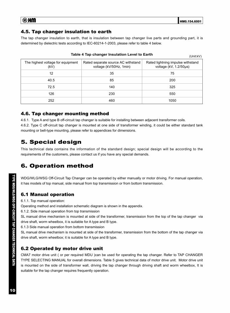
4.5. Tap changer insulation to earth The tap changer insulation to earth, that is insulation between tap changer live parts and grounding part, it is determined by dielectric tests according to IEC-60214-1-2003, please refer to table 4 below.
4.6. Tap changer mounting method 4.6.1. Type A and type B off-circuit tap changer is suitable for installing between adjacent transformer coils. 4.6.2. Type C off-circuit tap changer is mounted at one side of transformer winding, it could be either standard tank mounting or bell-type mounting, please refer to appendices for dimensions.
5. Special design This technical data contains the information of the standard design; special design will be according to the requirements of the customers, please contact us if you have any special demands.
6. Operation method
WDG/WLG/WSG Off-Circuit Tap Changer can be operated by either manually or motor driving. For manual operation, it has models of top manual, side manual from top transmission or from bottom transmission.
6.1 Manual operation 6.1.1. Top manual operation: Operating method and installation schematic diagram is shown in the appendix. 6.1.2. Side manual operation from top transmission SL manual drive mechanism is mounted at side of the transformer, transmission from the top of the tap changer via drive shaft, worm wheelbox, it is suitable for A type and B type. 6.1.3 Side manual operation from bottom transmission SL manual drive mechanism is mounted at side of the transformer, transmission from the bottom of the tap changer via drive shaft, worm wheelbox; it is suitable for A type and B type.
6.2 Operated by motor drive unit CMA7 motor drive unit ( or per required MDU )can be used for operating the tap changer. Refer to TAP CHANGER TYPE SELECTING MANUAL for overall dimensions. Table 5 gives technical data of motor drive unit. Motor drive unit is mounted on the side of transformer wall, driving the tap changer through driving shaft and worm wheelbox, It is suitable for the tap changer requires frequently operation.
Table 4 Tap changer Insulation Level to Earth
The highest voltage for equipment(kV)
Rated separate source AC withstandvoltage (kV/50Hz, 1min)
Rated lightning impulse withstandvoltage (kV, 1.2/50μs)
12 35 75
40.5 85 200
72.5 140 325
126 230 550
252 460 1050
(Unit:kV)

HM0.154.6001
TYPE WDG/W
LG/WSG OFF-CIRCUIT TAP CHANGER TECHNICAL DATA
11
7. Position indicator
7.1 HMC-3W off-circuit tap changer position indicator HMC-3W OCTC position indicator is a support fitting for CMA7 motor drive unit, it can be used to indicate the OCTC position in the control room.
HMC-3W technical data is as below. Working voltage: 220V AC Power frequency: 50Hz/60Hz Maximum operation positions: 39 Environment temperature: -10℃ to 40℃ Indoor Note: for special power supply please inform when ordering.
8. Accessories
Worm wheelbox is used connect the horizontal shaft of the tap changer and vertical shaft of the motor drive unit, by which transferring the driving torque from manual drive mechanism or motor drive unit to the tap changer.
9. Appendices
Table 5 Motor Drive Unit Technical Data
Motor drive unit CMA7
Motor
Rated power (W) 750 1100
Rated voltage (V) 380/3AC
Rated current (A) 2.0 2.8
Rate frequency(Hz) 50 or 60
Rotate speed (r.p.m.) 1400
Rated torque on drive shaft (Nm) 18 26
Revolution of the drive shaft per switching operation 33
Revolution of the hand crank per switching operation 33
Running time per switching operation (S) About 5
Max. operation positions 107
Voltage for control circuit and heater circuit (V) 220/AC
Heater power (W) 50
A.C. voltage test to ground (kV/50Hz, 1min) 2
Approx. weight (kg) 90
Protective degree IP56
Mechanical endurance (operations) Not less than 800,000

HM0.154.6001
TYPE WDG/W
LG/WSG OFF-CIRCUIT TAP CHANGER TECHNICAL DATA
12
Appendix 1 (WDG+WLG) IV-250-600A overall dimensions,linear regulation, A type
TypeDimensions (mm) operation
position(n)H H1 H3 ød/S(sectional area) ød1 ød2 ød4 hWDGIV-250~300/12~40.5-5×5A 505 445 -
250A:12.5/70300A:14.5/95400A:17.5/120500A:18.7/150600A:21.7/185
200 217
5
WLGIV-250~300/12~40.5-5×5A 770 710 295WDGIV-400~600/12~40.5-5×5A 505 445 -
220 237WLGIV-400~600/12~40.5-5×5A 770 710 265
WDGIV-250~300/72.5~126-5×5A 505 445 -200 217
WLGIV-250~300/72.5~126-5×5A 920 860 445WDGIV-400~600/72.5~126-5×5A 505 445 -
220 237WLGIV-400~600/72.5~126-5×5A 960 900 455
1. All connections have been made interior of the tap changer, only tap leads should be connected to the transformer winding(except special design)2. Length of tap lead is one meter.
d4=d
2+2d
3+δ
(δ≥6
0)
Thic
knes
s of
pap
erin
gh=
6(12
kV-4
0.5k
V)
h=12
(72.
5kV-
126k
V)

HM0.154.6001
TYPE WDG/W
LG/WSG OFF-CIRCUIT TAP CHANGER TECHNICAL DATA
13
Appendix 2 (WDG+WLG) IV-800-2000A overall dimensions,linear regulation, A type
TypeDimensions (mm) operation
position(n)H H1 H2 H3 ød/S(sectional area) ød1 ød2 ød4 hWDGIV-800~1000/12~40.5-5×5A 550 490
110-
800A:17.5/1201000A:18.7/1501250A:21.7/1851600A:24.7/2402000A:26/300
220 237 5
WLGIV-800~1000/12~40.5-5×5A 860 800 310WDGIV-1250/12~40.5-5×5A 625 565
130-
WLGIV-1250/12~40.5-5×5A 1010 950 430WDGIV-1600/12~40.5-5×5A 625 565
175-
WLGIV-1600/12~40.5-5×5A 1010 950 385WDGIV-2000/12~40.5-5×5A 670 610
220-
WLGIV-2000/12~40.5-5×5A 1100 1040 430WDGIV-800~1000/72.5~126-5×5A 550 490
110-
WLGIV-800~1000/72.5~126-5×5A 1050 990 500WDGIV-1250/72.5~126-5×5A 625 565
130-
WLGIV-1250/72.5~126-5×5A 1160 1100 580WDGIV-1600/72.5~126-5×5A 625 565
175-
WLGIV-1600/72.5~126-5×5A 1200 1140 575WDGIV-2000/72.5~126-5×5A 670 610
220-
WLGIV-2000/72.5~126-5×5A 1290 1230 6201. All connections have been made interior of the tap changer, only tap leads should be connected to the transformer winding(except special design)2. Length of tap lead is one meter.
d4=d
2+2d
3+δ
(δ≥6
0)
Thic
knes
s of
pap
erin
g h
=6(1
2kV-
40.5
kV)
h=12
(72.
5kV-
126k
V)

HM0.154.6001
TYPE WDG/W
LG/WSG OFF-CIRCUIT TAP CHANGER TECHNICAL DATA
14
Appendix 3 (WDG+WLG) V-250-600A overall dimensions,single-bridging regulation, A type
TypeDimensions (mm) operation
position(n)H H1 H3 ød/S(sectional area) ød1 ød2 ød4 hWDGV-250~300/12~40.5-6×5(4×3)A 465 405 -
250A:12.5/70300A:14.5/95400A:17.5/120500A:18.7/150600A:21.7/185
160 177
5
WLGV-250~300/12~40.5-6×5(4×3)A 730 670 295WDGV-250~300/12~40.5-8×7A 465 405 -
220 237WLGV-250~300/12~40.5-8×7A 730 670 295
WDGV-400~600/12~40.5-6×5(4×3)A 465 405 -160 177
WLGV-400~600/12~40.5-6×5(4×3)A 730 670 265WDGV-400~600/12~40.5-8×7A 465 405 -
220 237WLGV-400~600/12~40.5-8×7A 730 670 265
WDGV-250~300/72.5~126-6×5(4×3)A 465 405 -160 177
WLGV-250~300/72.5~126-6×5(4×3)A 880 820 445WDGV-250~300/72.5~126-8×7A 465 405 -
220 237WLGV-250~300/72.5~126-8×7A 880 820 445
WDGV-400~600/72.5~126-6×5(4×3)A 465 405 -160 177
WLGV-400~600/72.5v126-6×5(4×3)A 930 870 465WDGV-400~600/72.5~126-8×7A 465 405 -
220 237WLGV-400~600/72.5~ 126-8×7A 930 870 465
1. Length of tap lead is one meter.
d4=d
2+2d
3+δ
(δ≥6
0)
Thic
knes
s of
pap
erin
g h
=6(1
2kV-
40.5
kV)
h=12
(72.
5kV-
126k
V)
HM0.154.6001
TYPE WDG/W
LG/WSG OFF-CIRCUIT TAP CHANGER TECHNICAL DATA
15
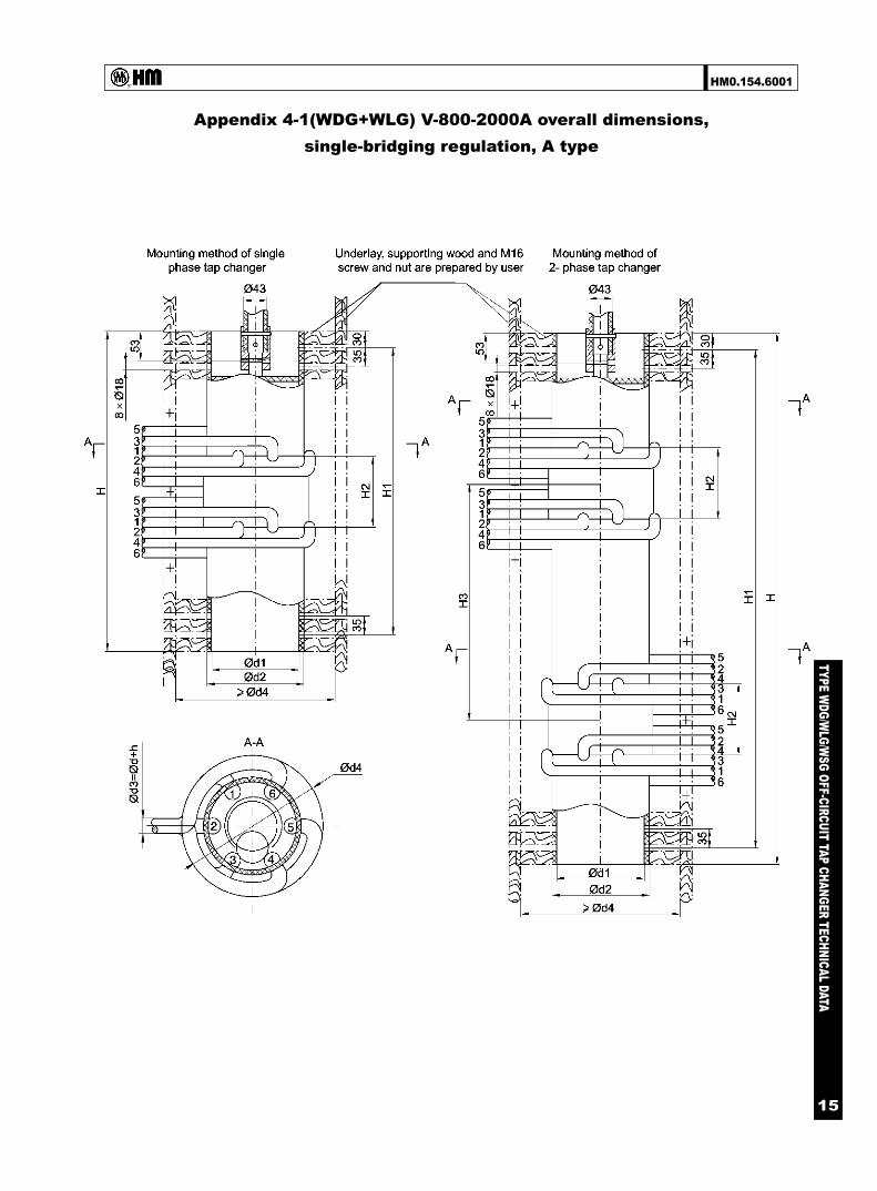
Appendix 4-1(WDG+WLG) V-800-2000A overall dimensions,single-bridging regulation, A type
HM0.154.6001
TYPE WDG/W
LG/WSG OFF-CIRCUIT TAP CHANGER TECHNICAL DATA
16
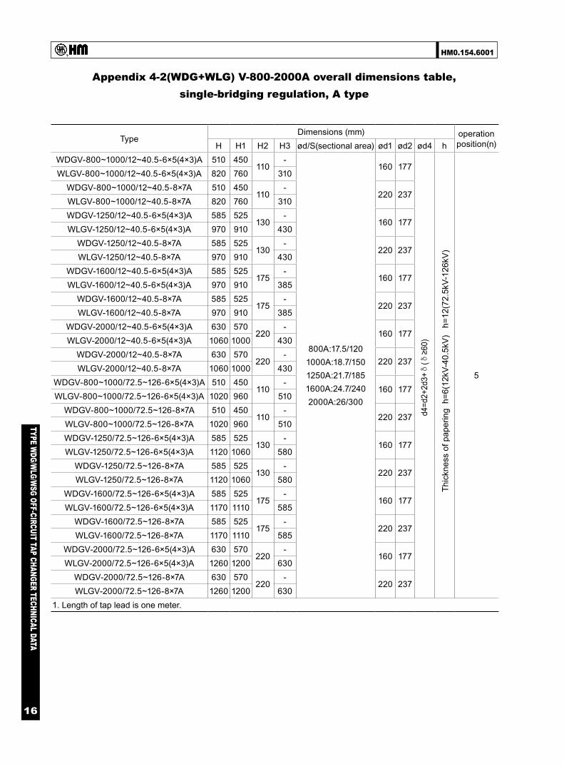
Appendix 4-2(WDG+WLG) V-800-2000A overall dimensions table,single-bridging regulation, A type
TypeDimensions (mm) operation
position(n)H H1 H2 H3 ød/S(sectional area) ød1 ød2 ød4 hWDGV-800~1000/12~40.5-6×5(4×3)A 510 450
110-
800A:17.5/1201000A:18.7/1501250A:21.7/1851600A:24.7/2402000A:26/300
160 177
5
WLGV-800~1000/12~40.5-6×5(4×3)A 820 760 310WDGV-800~1000/12~40.5-8×7A 510 450
110-
220 237WLGV-800~1000/12~40.5-8×7A 820 760 310WDGV-1250/12~40.5-6×5(4×3)A 585 525
130-
160 177WLGV-1250/12~40.5-6×5(4×3)A 970 910 430
WDGV-1250/12~40.5-8×7A 585 525130
-220 237
WLGV-1250/12~40.5-8×7A 970 910 430WDGV-1600/12~40.5-6×5(4×3)A 585 525
175-
160 177WLGV-1600/12~40.5-6×5(4×3)A 970 910 385
WDGV-1600/12~40.5-8×7A 585 525175
-220 237
WLGV-1600/12~40.5-8×7A 970 910 385WDGV-2000/12~40.5-6×5(4×3)A 630 570
220-
160 177WLGV-2000/12~40.5-6×5(4×3)A 1060 1000 430
WDGV-2000/12~40.5-8×7A 630 570220
-220 237
WLGV-2000/12~40.5-8×7A 1060 1000 430WDGV-800~1000/72.5~126-6×5(4×3)A 510 450
110-
160 177WLGV-800~1000/72.5~126-6×5(4×3)A 1020 960 510
WDGV-800~1000/72.5~126-8×7A 510 450110
-220 237
WLGV-800~1000/72.5~126-8×7A 1020 960 510WDGV-1250/72.5~126-6×5(4×3)A 585 525
130-
160 177WLGV-1250/72.5~126-6×5(4×3)A 1120 1060 580
WDGV-1250/72.5~126-8×7A 585 525130
-220 237
WLGV-1250/72.5~126-8×7A 1120 1060 580WDGV-1600/72.5~126-6×5(4×3)A 585 525
175-
160 177WLGV-1600/72.5~126-6×5(4×3)A 1170 1110 585
WDGV-1600/72.5~126-8×7A 585 525175
-220 237
WLGV-1600/72.5~126-8×7A 1170 1110 585WDGV-2000/72.5~126-6×5(4×3)A 630 570
220-
160 177WLGV-2000/72.5~126-6×5(4×3)A 1260 1200 630
WDGV-2000/72.5~126-8×7A 630 570220
-220 237
WLGV-2000/72.5~126-8×7A 1260 1200 6301. Length of tap lead is one meter.
d4=d
2+2d
3+δ
(δ≥6
0)
Thic
knes
s of
pap
erin
g h
=6(1
2kV-
40.5
kV)
h=1
2(72
.5kV
-126
kV)

HM0.154.6001
TYPE WDG/W
LG/WSG OFF-CIRCUIT TAP CHANGER TECHNICAL DATA
17
Appendix 5 (WDG+WLG) VI-250-1000A overall dimensions,Y-D change-over, A type
TypeDimensions (mm) operation
position(n)H H1 H3 ød/S(sectional area) ød1 ød2 ød4 hWDGVI-250-300/12-3×2A 465 405 - 250A:12.5/70
300A:14.5/95400A:17.5/120500A:18.7/150600A:21.7/185800A:24.7/2401000A:26/300
160 177 2
WLGVI-250-300/12-3×2A 670 610 235WDGVI-400-600/12-3×2A 465 405 -WLGVI-400-600/12-3×2A 670 610 205
WDGVI-800-1000/12-3×2A 510 450 -WLGVI-800-1000/12-3×2A 760 700 250
1. for 3 phase “O” is the neutral point which is connected by user (Otherwise specified).2. Length of tap lead is 1 meter.
d4=d
2+2d
3+δ
(δ≥6
0)
Thic
knes
s of
pa
perin
gh=
6(12
kV-4
0.5k
V)

HM0.154.6001
TYPE WDG/W
LG/WSG OFF-CIRCUIT TAP CHANGER TECHNICAL DATA
18
Appendix 6-1(WDG+WLG) VII-250-1000A overall dimensions,double-bridging regulation, A type

HM0.154.6001
TYPE WDG/W
LG/WSG OFF-CIRCUIT TAP CHANGER TECHNICAL DATA
19
Appendix 6-2(WDG+WLG) VII-250-1000A overall dimensionstable, double-bridging regulation, A type
TypeDimensions (mm) operation
position(n)H H1 H2 H3 ød/S(sectional area) ød1 ød2 ød4 hWDGVII-250~300/12~40.5-6×5(4×3)A 715 655
220-
250A:12.5/70300A:14.5/95400A:17.5/120500A:18.7/150600A:21.7/185800A:24.7/2401000A:26/300
160 177 5(3)WLGVII-250~300/12~40.5-6×5(4×3)A 1230 1170 575WDGVII-400~600/12~40.5-6×5(4×3)A 715 655
250-
WLGVII-400~600/12~40.5-6×5(4×3)A 1230 1170 515WDGVII-250~300/12~40.5-8×7A 715 655
220-
200 2177
WLGVII-250~300/12~40.5-8×7A 1230 1170 575WDGVII-400~600/12~40.5-8×7A 715 655
250-
220 237
WLGVII-400~600/12~40.5-8×7A 1230 1170 515WDGVII-800~1000/12~40.5-6×5(4×3)A 805 745
295
-5(3)
WLGVII-800~1000/12~40.5-6×5(4×3)A 1410 1350 605WDGVII-800~1000/12~40.5-8×7A 805 745 -
7WLGVII-800~1000/12~40.5-8×7A 1410 1350 605
WDGVII-250~300/72.5~126-6×5(4×3)A 790 730295
-
160 177 5(3)WLGVII-250~300/72.5~126-6×5(4×3)A 1530 1470 800WDGVII-400~600/72.5~126-6×5(4×3)A 790 730
325-
WLGVII-400~600/72.5~126-6×5(4×3)A 1580 1520 790WDGVII-250~300/72.5~126-8×7A 790 730
295-
200 2177
WLGVII-250~300/72.5~126-8×7A 1530 1470 800WDGVII-400~600/72.5~126-8×7A 790 730
325
220 237
WLGVII-400~600/72.5~126-8×7A 1580 1520 790WDGVII-800~1000/72.5~126-6×5(4×3)A 880 820
370
-5(3)
WLGVII-800~1000/72.5~126-6×5(4×3)A 1760 1700 880WDGVII-800~1000/72.5~126-8×7A 880 820 -
7WLGVII-800~1000/72.5~126-8×7A 1760 1700 880
1. Length of tap lead is one meter.
d4=d
2+2d
3+δ
(δ≥6
0)
Thic
knes
s of
pap
erin
g h
=6(1
2kV-
40.5
kV)
h=1
2(72
.5kV
-126
kV)

HM0.154.6001
TYPE WDG/W
LG/WSG OFF-CIRCUIT TAP CHANGER TECHNICAL DATA
20
Appendix 7 (WDG+WLG) VIII-250-1000A overall dimensions,series-parallel change-over, A type
TypeDimensions (mm) operation
position(n)H H1 H2 H3 ød/S(sectional area) ød1 ød2 ød4 hWDGVIII-250~300/12-3×2A 655 595
160-
250A:12.5/70300A:14.5/95400A:17.5/120500A:18.7/150600A:21.7/185800A:24.7/2401000A:26/300
160 177 2
WLGVIII-250~300/12-3×2A 1050 990 455WDGVIII-400~600/12-3×2A 655 595
190-
WLGVIII-400~600/12-3×2A 1050 990 395WDGVIII-800~1000/12-3×2A 745 685
235-
WLGVIII-800~1000/12-3×2A 1230 1170 485WDGVIII-250~300/40.5-3×2A 730 670
235-
WLGVIII-250~300/40.5-3×2A 1260 1200 590WDGVIII-400~600/40.5-3×2A 730 670
265-
WLGVIII-400~600/40.5-3×2A 1260 1200 530WDGVIII-800~1000/40.5-3×2A 820 760
310-
WLGVIII-800~1000/40.5-3×2A 1440 1380 6201. All connections have been made interior of the tap changer, only tap leads should be connected to the transformer winding(except special design)2.Length of tap leads is 1m
Thic
knes
s of
pap
erin
gh=
6(12
kV-4
0.5k
V)
d4=d
2+2d
3+δ
(δ≥6
0)
HM0.154.6001
TYPE WDG/W
LG/WSG OFF-CIRCUIT TAP CHANGER TECHNICAL DATA
21
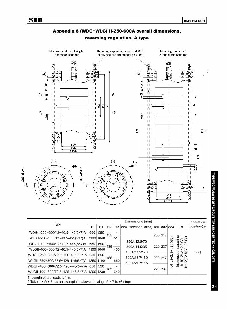
Appendix 8 (WDG+WLG) II-250-600A overall dimensions,reversing regulation, A type
TypeDimensions (mm) operation
position(n)H H1 H2 H3 ød/S(sectional area) ød1 ød2 ød4 hWDGII-250~300/12~40.5-4×5(5×7)A 650 590
155-
250A:12.5/70300A:14.5/95400A:17.5/120500A:18.7/150600A:21.7/185
200 217
5(7)
WLGII-250~300/12~40.5-4×5(5×7)A 1100 1040 510WDGII-400~600/12~40.5-4×5(5×7)A 650 590
185-
220 237WLGII-400~600/12~40.5-4×5(5×7)A 1100 1040 450
WDGII-250~300/72.5~126-4×5(5×7)A 650 590155
-200 217
WLGII-250~300/72.5~126-4×5(5×7)A 1250 1190 660WDGII-400~600/72.5~126-4×5(5×7)A 650 590
185-
220 237WLGII-400~600/72.5~126-4×5(5×7)A 1290 1230 6401. Length of tap leads is 1m.2.Take 4 × 5(± 2) as an example in above drawing , 5 × 7 is ±3 steps
Thic
knes
s of
pap
erin
gh=
6(12
kV-4
0.5k
V)
h=12
(72.
5kV-
126k
V)
d4=d
2+2d
3+δ
(δ≥6
0)

HM0.154.6001
TYPE WDG/W
LG/WSG OFF-CIRCUIT TAP CHANGER TECHNICAL DATA
22
Appendix 9 (WDG+WLG) II-800-1600A overall dimensions,reversing regulation, A type
TypeDimensions (mm) operation
position(n)H H1 H2 H3 H2 ød/S(sectional area) ød1 ød2 ød4 hWDGII-800~1000/12~40.5-4×5(5×7)A 740 680
110-
230
800A:17.5/1201000A:18.7/1501250A:21.7/1851600A:24.7/2402000A:26/300
220 237 5(7)
WLGII-800~1000/12~40.5-4×5(5×7)A 1280 1220 540WDGII-1250/12~40.5-4×5(5×7)A 800 740
130-
260WLGII-1250/12~40.5-4×5(5×7)A 1400 1340 600WDGII-1600/12~40.5-4×5(5×7)A 890 830
175-
305WLGII-1600/12~40.5-4×5(5×7)A 1580 1520 690
WDGII-800~1000/72.5~126-4×5(5×7)A 740 680110
-230
WLGII-800~1000/72.5~126-4×5(5×7)A 1470 1410 730WDGII-1250/72.5~126-4×5(5×7)A 800 740
130-
260WLGII-1250/72.5~126-4×5(5×7)A 1590 1530 790WDGII-1600/72.5~126-4×5(5×7)A 890 830
175-
305WLGII-1600/72.5~126-4 × 5(5×7)A 1770 1710 880
1. Length of tap leads is 1m.2.Take 4 × 5(± 2) as an example in above drawing , 5 × 7 is ± 3 steps
Thic
knes
s of
pap
erin
gh=
6(12
kV-4
0.5k
V)
h=12
(72.
5kV-
126k
V)
d4=d
2+2d
3+δ
(δ≥6
0)
HM0.154.6001
TYPE WDG/W
LG/WSG OFF-CIRCUIT TAP CHANGER TECHNICAL DATA
23
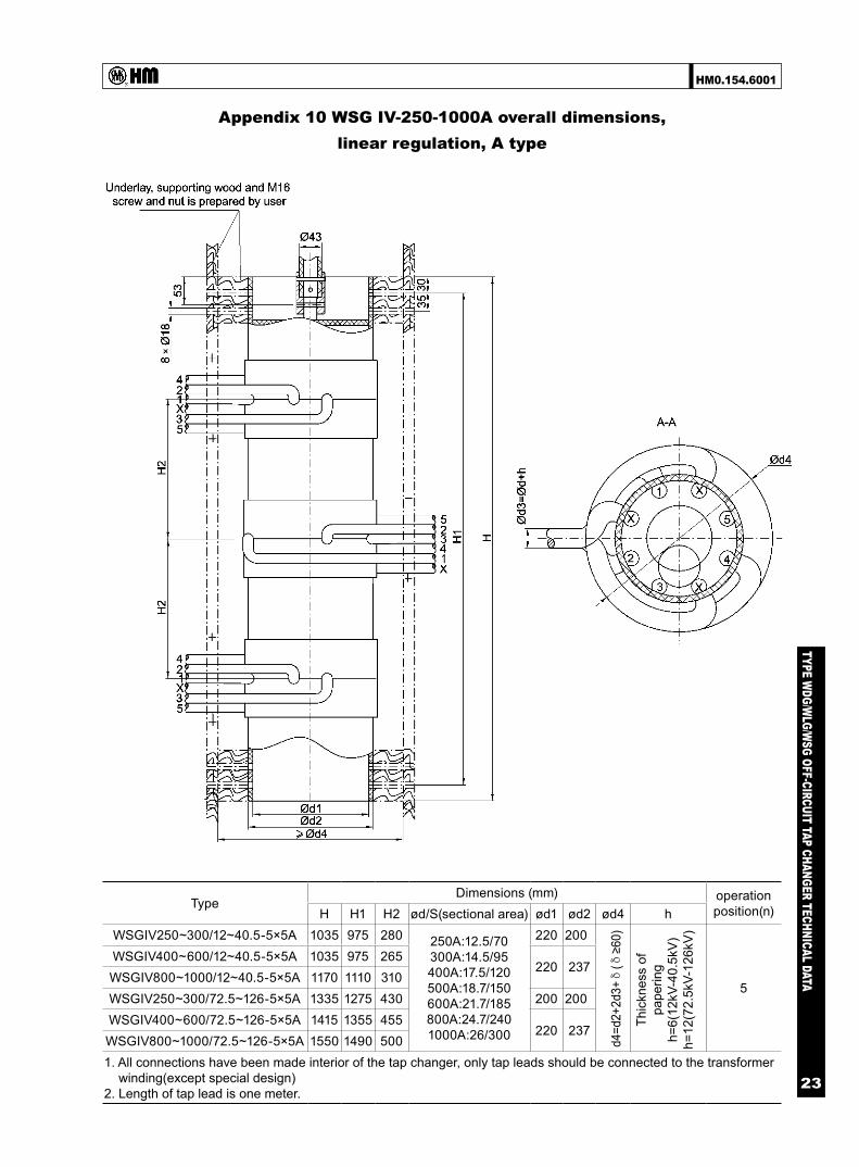
Appendix 10 WSG IV-250-1000A overall dimensions,linear regulation, A type
TypeDimensions (mm) operation
position(n)H H1 H2 ød/S(sectional area) ød1 ød2 ød4 hWSGIV250~300/12~40.5-5×5A 1035 975 280 250A:12.5/70
300A:14.5/95400A:17.5/120500A:18.7/150600A:21.7/185800A:24.7/2401000A:26/300
220 200
5
WSGIV400~600/12~40.5-5×5A 1035 975 265220 237
WSGIV800~1000/12~40.5-5×5A 1170 1110 310WSGIV250~300/72.5~126-5×5A 1335 1275 430 200 200WSGIV400~600/72.5~126-5×5A 1415 1355 455
220 237WSGIV800~1000/72.5~126-5×5A 1550 1490 5001. All connections have been made interior of the tap changer, only tap leads should be connected to the transformer winding(except special design)2. Length of tap lead is one meter.
Thic
knes
s of
pa
perin
gh=
6(12
kV-4
0.5k
V)
h=12
(72.
5kV-
126k
V)
d4=d
2+2d
3+δ
(δ≥6
0)

HM0.154.6001
TYPE WDG/W
LG/WSG OFF-CIRCUIT TAP CHANGER TECHNICAL DATA
24
Appendix 11 WSG V-250-1000A overall dimensions,single-bridging regulation, A type
TypeDimensions (mm) operation
position(n)H H1 H2 ød/S(sectional area) ød1 ød2 ød4 hWSGV-250~300/12~40.5-6×5A 995 935 280 250A:12.5/70
300A:14.5/95400A:17.5/120500A:18.7/150600A:21.7/185800A:24.7/2401000A:26/300
160 177 5
WSGV-400~600/12~40.5-6×5A 995 935 265WSGV-800~1000/12~40.5-6×5A 1130 1070 310WSGV-250~300/72.5~126-6×5A 1295 1235 430WSGV-400~600/72.5~126-6×5A 1395 1335 465WSGV-800~1000/72.5~126-6×5A 1530 1470 5101. Length of tap lead is one meter.
Thic
knes
s of
pa
perin
gh=
6(12
kV-4
0.5k
V)
h=12
(72.
5kV-
126k
V)
d4=d
2+2d
3+δ
(δ≥6
0)

HM0.154.6001
TYPE WDG/W
LG/WSG OFF-CIRCUIT TAP CHANGER TECHNICAL DATA
25
Appendix 12 WSG II-250-1000A overall dimensions,reversing regulation, A type
TypeDimensions (mm) operation
position(n)H H1 H2 H3 ød/S(sectional area) ød1 ød2 ød4 hWDGII-250~300/12~40.5-4×5(5×7)A 1550 1490 155 480 250A:12.5/70
300A:14.5/95400A:17.5/120500A:18.7/150600A:21.7/185800A:24.7/2401000A:26/300
200 217
5(7)
WDGII-400~600/12~40.5-4×5(5×7)A 1550 1490 185 450 220 237WDGII-800~1000/12~40.5-4×5(5×7)A 1820 1760 230 540 220 237WDGII-250~300/72.5~126-4×5(5×7)A 1910 1850 155 660 200 217WDGII-400~600/72.5~126-4×5(5×7)A 1930 1870 185 640 220 237WDGII-800~1000/72.5~126-4×5(5×7)A 2200 2140 230 730 220 2371. Length of tap leads is 1m.2.Take 4 × 5(± 2) as an example in above drawing , 5 × 7 is ± 3 steps
Thic
knes
s of
pa
perin
gh=
6(12
kV-4
0.5k
V)
h=12
(72.
5kV-
126k
V)
d4=d
2+2d
3+δ
(δ≥6
0)

HM0.154.6001
TYPE WDG/W
LG/WSG OFF-CIRCUIT TAP CHANGER TECHNICAL DATA
26
Appendix 13 WDG V-250-2000A overall dimensions,single-bridging regulation, B type
TypeDimensions (mm) operation
position(n)Lead
come outL L1 ød/S(sectional area) ød1 ød2 ød3 h
WDGV-250~300/12~40.5-6×5B600
≤178
250A:12.5/70 300A:14.5/95
237 220 250
5
frombottomWDGV-400~600/12~40.5-6×5B 400A:17.5/120 500A:18.7/150 600A:21.7/185
WDGV-800/12~40.5-6×5B
700
17.5/120
fromtwo
ends
WDGV-1000/12~40.5-6×5B 18.7/150WDGV-1250/12~40.5-6×5B 21.7/185WDGV-1600/12~40.5-6×5B 24.7/240WDGV-2000/12~40.5-6×5B 26/300
WDGV-250~300/72.5~126-6×5B
700
≤207.5
250A:12.5/70 300A:14.5/95 frombottomWDGV-400~600/72.5~126-6×5B 400A:17.5/120 500A:18.7/150 600A:21.7/185
WDGV-800/72.5~126-6×5B 17.5/120
fromtwo
ends
WDGV-1000/72.5~126-6×5B 18.7/150WDGV-1250/72.5~126-6×5B
80021.7/185
WDGV-1600/72.5~126-6×5B 24.7/240WDGV-2000/72.5~126-6×5B 26/300WDGV-250~300/252-6×5B
1000 ≤372.5
250A:12.5/70 300A:14.5/95
300 280 340
frombottomWDGV-400~600/252-6×5B 400A:17.5/120 500A:18.7/150 600A:21.7/185
WDGV-800/252-6×5B 17.5/120
fromtwo
ends
WDGV-1000/252-6×5B 18.7/150WDGV-1250/252-6×5B 21.7/185WDGV-1600/252-6×5B 24.7/240WDGV-2000/252-6×5B 26/300
1. Length of tap lead is one meter.
Thic
knes
s of
pap
erin
g h
=6(1
2kV-
40.5
kV)
h=1
2(72
.5kV
-126
kV) h
=20(
252k
V)

HM0.154.6001
TYPE WDG/W
LG/WSG OFF-CIRCUIT TAP CHANGER TECHNICAL DATA
27
Appendix 14 WDG IV-250-2000A overall dimensions,linear regulation, B type
TypeDimensions (mm) operation
position(n)Lead
come outL L1 ød/S(sectional area) ød1 ød2 ød3 h
WDGIV-250~300/252-5×5B
1000 ≤372.5
250A:12.5/70,300A:14.5/95
300 280 340 5
frombottomWDGIV-400~600/252-5×5B 400A:17.5/120 500A:18.7/150 600A:21.7/185
WDGIV-800/252-5×5B 17.5/120
fromtwo
ends
WDGIV-1000/252-5×5B 18.7/150WDGIV-1250/252-5×5B 21.7/185WDGIV-1600/252-5×5B 24.7/240WDGIV-2000/252-5×5B 26/300
1. Length of tap lead is one meter.
Thic
knes
s of
pap
erin
gh=
6(12
kV-4
0.5k
V)
h=12
(72.
5kV-
126k
V)
h=20
(252
kV)

HM0.154.6001
TYPE WDG/W
LG/WSG OFF-CIRCUIT TAP CHANGER TECHNICAL DATA
28
Appendix 15 Top manual driving mechanism,overall dimensions, for A and B type
Unit: mm
HM0.154.6001
TYPE WDG/W
LG/WSG OFF-CIRCUIT TAP CHANGER TECHNICAL DATA
29
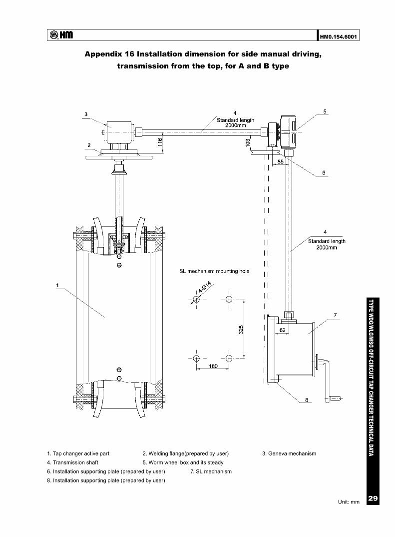
Appendix 16 Installation dimension for side manual driving,transmission from the top, for A and B type
Unit: mm
1. Tap changer active part 2. Welding flange(prepared by user) 3. Geneva mechanism
4. Transmission shaft 5. Worm wheel box and its steady
6. Installation supporting plate (prepared by user) 7. SL mechanism
8. Installation supporting plate (prepared by user)

HM0.154.6001
TYPE WDG/W
LG/WSG OFF-CIRCUIT TAP CHANGER TECHNICAL DATA
30
Appendix 17 (WDG+WLG) installation dimension for sidemanual driving, transmission from the bottom, for A and B type
Unit: mm
1. Tap changer body 2 . Insulation shaft 3. Supporting frame(prepared by user)
4. Gearbox 5. Drive shaft 6. Welding flange(prepared by user)
7. Flange

HM0.154.6001
TYPE WDG/W
LG/WSG OFF-CIRCUIT TAP CHANGER TECHNICAL DATA
31
Appendix 18 Installation dimensions of motor driving tap changer,for A and B type
Unit: mm
1. Tap changer active part 2. Welding flange(prepared by user) 3. Geneva wheelbox
4. Transmission shaft 5. Worm wheel box and its steably
6. Installation supporting plate (prepared by user) 7. CMA7 motor drive unit
8. Inatallation supporting plate (prepared by user)
Remark: According to users’ different requirements, offer relative operation mechanism and matched indicator & controller

HM0.154.6001
TYPE WDG/W
LG/WSG OFF-CIRCUIT TAP CHANGER TECHNICAL DATA
32
Appendix 19 Overall dimension of geneva mechanism
Unit: mm

HM0.154.6001
TYPE WDG/W
LG/WSG OFF-CIRCUIT TAP CHANGER TECHNICAL DATA
33
Appendix 20 Installation dimension of worm wheel box andits steady (suitable for type A and type B)
Unit: mm

HM0.154.6001
TYPE WDG/W
LG/WSG OFF-CIRCUIT TAP CHANGER TECHNICAL DATA
34
Appendix 21 WSG II-400-1600A overall dimensions, reversing regulation, C type
TypeDimensions (mm) operation
position(n)H H1 H2 H3 H4WSGII-400~600/12~40.5-4×5C(5×7)C 1418 285.5 215 185 132.5
5(7)WSGII-800~1000Y/12~40.5-4×5C(5×7)C 1688 308 260 230 155
WSGII-1250Y/12~40.5-4×5C(5×7)C 1868 323 290 260 170WSGII-1600Y/12~40.5-4×5C(5×7)C 2138 345.5 335 305 192.5
WSGII-400~600Y/72.5~126-4×5C(5×7)C 1652 400 270 185 137.5

HM0.154.6001
TYPE WDG/W
LG/WSG OFF-CIRCUIT TAP CHANGER TECHNICAL DATA
35
Appendix 22 Head flange for standard tank,overall dimension, hand wheel operating on top, C type
Appendix 23 Transformer mounting flange for standard tank,overall dimension, C type
Unit: mm

HM0.154.6001
TYPE WDG/W
LG/WSG OFF-CIRCUIT TAP CHANGER TECHNICAL DATA
36
Appendix 24 Head flange for bell-type, overall dimension,hand wheel operating on top, C type
Appendix 25 Bell-type supporting flange, overall dimension, C type
Unit: mm

HM0.154.6001
TYPE WDG/W
LG/WSG OFF-CIRCUIT TAP CHANGER TECHNICAL DATA
37
Appendix 26 SL manual drive mechanism,overall dimensions
Unit: mm

69
TYPE VCM O
IL-IMM
ERSED ON
-LOAD TAP CH
ANG
ER TECHN
ICAL DATA
HM0.154.5701
Printing: FEB.2010
SHANGHAI HUAMING POWER EQUIPMENT CO., LTD.
Address: 977 Tong Pu Road, Shanghai, P.R.China 200333Tel: +86 21 5270 3965(direct)
+86 21 5270 8966 Ext.8688/8123/8698/8158/8110/8658
Fax: +86 21 5270 2715Web:www.huaming.com
E-mail: [email protected]