technical description -...
TRANSCRIPT

ELECTRICAL AND MECHANICAL VEHICLE G 222 ENGINEERING INSTRUCTIONS Issue 1, Jul 89
0 TRUCK, AMBULANCE, LIGHT, 4 LITTER, FFR, WINCH, MC2 - LAND ROVER 110 6 x 6
TECHNICAL DESCRIPTION This instruction is authorised for use by command of the Chief of the General Staff. It provides direction, mandatory controls and procedures for the operation, maintenance and support of equipment. Personnel are to carry out any action required by this instruction in accordance with GENERAL A 001.
UN
CO
NT
RO
LLE
D W
HE
N P
RIN
TE
D

ELECTRICAL AND MECHANICAL VEHICLE G 222 ENGINEERING INSTRUCTIONS Issue 1, Ott 89
AMENDMENT CERTIFICATE It is certified that the amendments promulgated in the undermentioned Amendment Lists have been incorporated in this
..I
..,
..,
. .
. . .
.
. .
. . .
. .
,..
. .
.
. .
. .
. . .
of the Publication:
Amendment List Topic/Section *Amendment Effect Amended By Date
Vo. Date of Issue Affected (Print Name)
1 7-v [od&wf G -cA-i!d
,.......................................................... . . . . . . . . . . . . . . . . . . . . . . . . . . . . . . . . . . . . . . . . . . . . . . . . . . . . . . . . . . . . . . . . . . . . . . +p .._........................................... .
2 ~....................................................... . . . . . . . . . . . . . . . . . . . . . . . . . . . . . . . . . . . . . . . ,. . . . . . . . . . . . . . . . . .__............................ . . . . . . . . . . . . .
3 . . . . . . . . . . . . . . . . . . . . . . . . . . . . . . . . . . . . . . . . . . . . . . . . . . . . . . . . . . . . . . . . . . . . . . . . . . . . . . . . . . . . . . . . . . . . . . . . . . . . . . . . . . . ,.......... . . . . . . ..................... ..........,......,... ..,
4 . . . . . . . . . . . . . . . . . . . . . . . . . . . . . . . . . . . . . . . . . . . . . . ..,..__._............................................................. . . . . . . . . . . . . . . . . . . . . .___............,. .
5 ~..........................................................~ . . . . . . . . . . . . . . . . . . . . . . . . . . . . . . . . . . . . . . . . . . . ..,................ . . .
6 . . . . . . . . . . . . . . . . . . . . . . . . . . . . . . . . . . . . . . . . . . . . . . . . . . . . . . . . . . ..,_,_.................... . . . ,.,.................. ..,.,.,.. . . . . . . . . . . . . . . . . . . . . . . . . . . . .
7 . . . . . . . . . . . . . . . . . . . . . . . . . .,. . . . . . . . . . . . . . . . . . . . . . . . . . . . . . . . .,............,.,..........,....... ..,.,.,.,....,.,., . . . . . . . . . . . . _.,..._..,...._...,
8 . . . . . . . . . . . . . . . . . . . . . . . . . . . . . . . . . . . . . . . . . . . . . . .._._._.................._ . . . . . . . . . . . . . . . . . . . .,.............., ,. .
9 . . . . . . . . . . . . . . . . . . . . . . . . . . . . . . . . . . . . . . . . . . . . . . . .,.,................,.,.,.......................,.,., . . . . .,.,. .,. ,.,.,. .,. ,,.,.,.,..
10 . . . . . . . . . . . . . . . . . . . . . . . . . . . . . . . . . . . . . . . . . . . . . . . . . . . . . . . . . . . . . . . . . . . . . . . . . .,...,.....................,.............. .,.,., . . . . . . . . . . ..,.,. . . . . .
11 . . . . . . . . . . . . . . . . . . . . . . . . . . . . . . . . . . . . . . . . . . . . . . . . . . . . . . . . . . . . . . . . ..,..................,.,..............,.,., .,.......... . .,.,... . . . . . ..,......
12 . . . . . . . . . . . . . . . . . . . . . . . . . . . . . ..~.......................... . . . . . . . . . . . . . . . . . . . . . . . . . . . . . . . . . . . . . . . . . . . . . . .......
13 . . . . . . . . . . . . . . . . . . . . . . . . . . . . . . . . . . . . . . . . . . . . . . ..,........ . . . . . . . . . . . . . . . . . . . . . . . . . . . . . . . . . . . . . . . . . ..,.,...................,. .,..._.......,..
14 . . . . . . . . . . . . . . . . . . . . . . . . . . . . . . . . . . . . . . . . . . . . . . . . . . . . . . . . . . . . . . . . . . . . . . . . . ._._._............., . . . . . . . . . . . . . . . . . . . . .... ..... .....
15 . . . . . . . . . . . . . . . . . . . . . . . . . . . . . . . . . . . . . . . . . . . . . . . . . . . . . . . . . .._._._.................................. . . . . . . . . . . . . . . . . . . . . . . . . . . . ..*......
16 . . . . . . . . . . . . . . . . . . . . . . . . . . . . . . . . . . . . . . . . . . . . . . . . . . . . . . .,....................... .,............,. . . . . . . . . . . . . . . . .
17 . . . . . . . . . . . . . . . . . . . . . . . . . . . . . . . . . . . . . . . . . . . . . . . . . . . . . . . . . . . . . . . . . . . . . . . . . . . . . . . . . . . . . . . . . . . .., ........ ..... ................... ...
18 . . . . . . . . . . . . . . . . . . . . . . . . . . . . . . . .._..._..._............. ..,........ .,.,.,...,. . . . . . . . . . . . . . . . . . . . . . . . . . . .
19 . . . . . . . . . . . . . . . . . . . . . . . . . . . . . . . . . . . . . . . . . . . . . . . . . . . . . . . . . . . . . . . . . . . . . . . . . . . . .. .. .................................. ..
20 . . . . . . . . . . . . . . . . . . . . . . . . . . . . . . . . . . . . . . . . . . . . . . . . . . . . . . . . . . . . . ., . . . . . . . . . . . . . . . . . . . . . . . . . . . . . . . . . . . . . . . . . . . . . . . . ,,, ,..
21 . . . . . . . . . . . . . . . . . . . . . . . . . . . . . . . . . . . . . . . . . . . . . . . . . . . . . . . . . . . . . . . . . . . . . . . . . . . . . . . . . . . . . . . . . . . . . . . . . . . . .....,.,.,.,.,....,. ,. ...,_,.,.,.,.,
22 . . . . . . . . . . . . . . . . . . . . . . . . . . . . . . . . . . . . . . . . . . . . . . . . . . . . . . . . . . . . . . . . . . . . . . . . . . . . . . . . . . . . . . . . . . . . . . . . . . . . . . . . . . . . ................................,. .......,,,.......,
23 . . . . . . . . . . . . . . . . . . . . . . . . . . . . . . . . . . . . . . . . . . . . . . . . . . ~............... . . . . . . . . . . . . ..,.,....................,...... ._,......,. .,.....
24 . . . . . . . . . . . . . . . . . . . . . . . . . . . . . . . . . . . . . . . . . . . . . . . . . . . . . . . . . . ..,... . . . . . . . . . . . . . . . . . . . . . . . . . . . . . . . . . . . . . . . . . . . . . . . . . ..,.,.,......,_,.,.,.,.,.,..........,.,.,.,.,... .,.
25
*Note: Insert EMEI amendment number and page number OR brief details of page(s) amended, inserted or cancelled.
UN
CO
NT
RO
LLE
D W
HE
N P
RIN
TE
D

VEHICLE G222 ELECTRICAL AND MECHANICAL Issue 1, Ott 89 ENGINEERING INSTRUCTIONS
AMENDMENT CERTIFICATE (Continued)
Amendment List Topic/Section *Amendment Effect Amended By Date
Uo. Date of Issue Affected (Print Name)
26 ....... ........................ ..........................................................................................................................................................
27 ....... ........................ ..........................................................................................................................................................
28 ....... ........................ ..........................................................................................................................................................
29 ....... ..................... ..........................................................................................................................................................
30 ....... ........................ .......................................................................................................................................... ...............
31 ....... ........................ ..........................................................................................................................................................
32 ....... ........................ ..........................................................................................................................................................
33 ........ ........................ ..........................................................................................................................................................
34 ....... ........................ ..........................................................................................................................................................
35 ........ ........................ ..........................................................................................................................................................
36 ................................. ......................................................................................... ..............................................................
37 ........ ........................ ................................... ............ .........................................................................................................
38 ............. ................. .......................................................................................... ..................................... .........................
39 ................................. .......................................... ......................................... .....................................................................
40 ................................. ............................................. .................. ...................... .......................... .... .............................. ...
41 ........ ........................ .........................................................................................................................................................
42 ................................. ..........................................................................................................................................................
43 ........ .............................................................................. ....................................................................................................
44 ........ .................................................................................. ........................................................................................
45 ........ .............. ......... ................................................................ ... .............................................................................
46 ........ ........................ ................................................... ................ ........................................................ ..........................
47 ........ ........................ ............................................................ .............................................................................................
48 ........ ........................ ........................................................................................................ ................................................
49 ........ ........................ .........................................................................................................................................................
50
. .
. .
. .
. .
. .
.
.
.
. .
.
.
,..
,..
.
- *Note: Insert EMEI amendment number and page number OR brief details of page(s) amended, inserted or
cancelled.
UN
CO
NT
RO
LLE
D W
HE
N P
RIN
TE
D

ELECTRICAL AND MECHANICAL VEHICLE G 222 ENGINEERING INSTRUCTIONS Issue 1, Ott 89
LIST OF CONTENTS
Para No. Page No.
I AMENDMENT CERTIFICATE ......................................................................................... LIST OF CONTENTS.. ..................................................................................................... LIST OF ILLUSTRATIONS.. ............................................................................................ LIST OF TABLES ............................................................................................................ ASSOCIATED PUBLICATIONS.. .................................................................................... MAINTENANCE SUPPLY ITEMS (MSI) IDENTlFlCATlON ............................................
INTRODUCTION.. ............................................................................................................
GENERAL INFORMATION ............................................................................................. Ambulance Module ......................................................................................................
DETAILED DESCRIPTION Ambulance Module
Construction.. ......................................................................................................... Rear Door.. ............................................................................................................ Rear Door Gas Struts ............................................................................................ Stepped Floor.. .................................................................................................... Rear Step.. ............................................................................................................. Communication Opening ....................................................................................... Litter Rails.. ............................................................................................................ Stowage Bin.. ......................................................................................................... Seat Belts .............................................................................................................. Tumble Out Bins.. .................................................................................................. Medical Assistants Seat.. ....................................................................................... Open Face Locker.. ............................................................................................... Stowage Locker.. ................................................................................................... Body Waste Disposal Hatch ..................................................................................
Engine Air Conditioner Compressor ..................................................................................
Electrical System .......................................................................................................... Alternator ............................................................................................................... Wiring Harnesses .................................................................................................. Power Distribution Box (PDB). ............................................................................... Batteries.. ............................................................................................................... Hourmeter.. ............................................................................................................ Ammeter ................................................................................................................
Lighting, Warning Devices and Switches Individual Litter Lights and Switches. ..................................................................... Module Interior Ceiling Lights (Clear) .................................................................... Module Interior Blackout Lights ............................................................................. Rear Loading Lights.. ............................................................................................. Scan Lights.. .......................................................................................................... Casualty Observation Stalk Lights.. ....................................................................... High Level Stop, Tail and Warning Lamps ............................................................ High Level Reversing Lights.. ................................................................................ High Level Indicator Lights .................................................................................... Module Interior Low Power Lights ......................................................................... Communication Buzzer Switch.. ............................................................................ Main Switch Panel ................................................................................................. Secondary Switch Panel.. ...................................................................................... Master Switch ........................................................................................................ Rotating Beacon Lights.. ........................................................................................
i . . . III iv V
vi
1
1 2 1
3 5 6 7 8 9
10 11 12 13 14 15 16 17
1 2 2 2 3 3 3 3 3 3 3 3 3 3
18 20 21 32 34 35 36 37
38 7 39 7 40 7 41 8 42 8 43 8 44 8 45 8 46 8 47 9 48 9 49 9 50 9 52 10 53 10
AL1
UN
CO
NT
RO
LLE
D W
HE
N P
RIN
TE
D

VEHICLE G 222 ELECTRICAL AND MECHANICAL Issue 1, Ott 89 ENGINEERING INSTRUCTIONS
Air Conditioning System Compressor.. ......................................................................................................... Condensor ............................................................................................................. Evaporator ............................................................................................................. Receiver Drier.. ...................................................................................................... Refrigerant Hose ...................................................................................................
Heating and Ventilation Heater.. ..................................................................................................................
Fuses and Relays ........................................................................................................
Suction/Vacuum Pump ................................................................................................
Audible Warning Device/Speaker ................................................................................
Para No. Page No.
54 10
56 10 60 11 66 12
67 12
68 12 70 12 71 12 72 13
ii AL1
UN
CO
NT
RO
LLE
D W
HE
N P
RIN
TE
D

ELECTRICAL AND MECHANICAL VEHICLE G 222 ENGINEERING INSTRUCTIONS Issue 1, 013 89
0 LIST OF ILLUSTRATIONS
0 Flg. No. Title
1 2 3 4 5 6 7 8 9
10 11 12 13 14 15 16 17 18 19 20 21 22 23 24
0 25 26 27 28 29 30 31 32 33
Truck, Ambulance, Light, 4 Litter, FFR, Winch, MC2 ...............................................................
Ambulance Module.. .................................................................................................................... Module Lifting Beam.. .................................................................................................................. Rear Door ..................................................................................................................................... Rear Step.. .................................................................................................................................... Communication Opening.. ........................................................................................................... Air Conditioner Compressor.. ...................................................................................................... Alternator - Exploded View.. .....................................................................................................
Stator Housing Assembly ........................................................................................................... Inductor Rotor and Cooling Fan .................................................................................................
Regulator/Rectifier Assembly .................................................................................................... Regulator Sub-assembly.. ........................................................................................................... Rectifier Assembly.. ..................................................................................................................... Output Connector and RF Filter ................................................................................................ Alternator Circuit Diagram ........................................................................................................... Power Distribution Box ................................................................................................................ Litter Light and Switches.. ........................................................................................................... Dome Lights - Location.. ........................................................................................................... Interior Blackout Lights - Location ........................................................................................... Loading Lights - Location .........................................................................................................
Scan Lights - Location .............................................................................................................. Casualty Observation Stalk Lights - Location.. .......................................................................
High Level Lights - Location.. ...................................................................................................
Low Power Lights - Location .................................................................................................... Main Switch Panel.. ...................................................................................................................... Secondary Switch Panel.. ............................................................................................................ Rotating Beacon Lights - Location ..........................................................................................
Air Conditioner Compressor - Sectional View.. .......................................................................
Roof Mounted Condensor - Exploded View.. .......................................................................... Air Conditioner Evaporator - Exploded View ..........................................................................
Heater Assembly.. ........................................................................................................................ Suction/Vacuum Pump ............................................................................................................... Audible Warning Device/Speaker.. ............................................................................................
Page No.
1 2 2 2 3 3 4 4 4 5 5 5 5 6 6 7 7 7 8 8 8 8 9 9 9 9
10 10 10 11 12 12 13
UN
CO
NT
RO
LLE
D W
HE
N P
RIN
TE
D

VEHICLE G 222 Issue 1, Ott 89
LIST OF TABLES
ELECTRICAL AND MECHANICAL ENGINEERING INSTRUCTIONS
Table No. Title Page No.
1 Location of Identification Numbers on Maintenance Supply Items . . . . . . . . . . . . . . . . . . . . . . . . . . . . . . . . . . . . . . . . . ’ 2 Globe Wattage - Module . . . . . . . . . . . . . . . . . . . . . . . . . . . . . . . . . . . . . . . . . . . . . . . . . . . . . . . . . . . . . . . . . . . . . . . . . . . . . . . . . . . . . . . . . . . . . . . . . . . . . . . . . . . l”d
iv
UN
CO
NT
RO
LLE
D W
HE
N P
RIN
TE
D

ELECTRICAL AND MECHANICAL ENGINEERING INSTRUCTIONS
VEHICLE G 222 Issue 1, Ott 89
ASSOCIATED PUBLICATIONS
1. Standing Orders for Vehicle Operation and Servicing (Vol. 2 - B Vehicles)
2. MEMA Vol. 3
3. Australian Army Books: TGM 120 Record Book for Service Equipment - Army
4. Complete Equipment Schedules (CES):
(a) SCES 12100 Truck, Ambulance, Light,
(b) Equipment Kit SCES 12068/2 4 Litter, FFR, Winch, MC2
5. Block Scale 2406131 Issue 1 - Special Tools for RAEME - B Vehicles - Truck Utility and Truck Light MC2 (Land Rover Model 110)
6. EMEI VEH A 029 - Servicing of B Vehicles
7. EMEI VEH A 119-22 - Repair of Vehicles Under Warranty Agreement - Policy Instruction
8. EMEI VEH G 220 - Data Summary (Truck, Ambulance, Light, FFR, Winch)
9. EMEI VEH G 202 -Technical Description (Truck, Cargo, Light)
10. EMEI VEH G 203 - Unit Repair (Truck, Cargo, Light)
11. EAAEI VEH G 223 - Unit Repair (Truck, Ambulance, Light, FFR, Winch)
12. EMEI VEH G 204 - Field Repair (Truck, Cargo, Light)
13. EMEI VEH G 204-l - Base Repair (Truck, Cargo, Light)
14. EMEI VEH G 224-l - Field and Base Repair (Truck, Ambulance, Light, FFR, Winch)
15. EMEI WKSP E 652 -Occupational Health and Safety (Polyurethane Paint)
16. EMEI ELEC P 413 - Generator, Engine Accessory, 28V DC, 100 AMP Unit Repair.
17. EMEI ELEC P 414-1 - Generator, Engine Accessory, 28V DC, 100 AMP Field Repair.
18. EMEI VEH G 209 - Servicing Instruction
19. Australian Change in War Materiel 31422
20. Repair Parts Scale 02208
UN
CO
NT
RO
LLE
D W
HE
N P
RIN
TE
D
VEHICLE G 222 Issue 1, Ott 89
ELECTRICAL AND MECHANICAL ENGINEERING INSTRUCTIONS
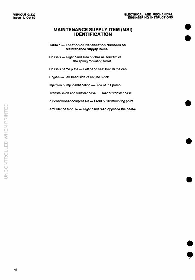
MAINTENANCE SUPPLY ITEM (MI) IDENTIFICATION
Table 1 - Location of Identification Numbers on Maintenance Supply Items
Chassis - Right hand side of chassis, forward of the spring mounting turret
Chassis name plate - Left hand seat box, in the cab
Engine - Left hand side of engine block
Injection pump identification - Side of the pump
Transmission and transfer case - Rear of transfer case
Air conditioner compressor - Front outer mounting point
Ambulance module - Right hand rear, opposite the heater
Vi
UN
CO
NT
RO
LLE
D W
HE
N P
RIN
TE
D

ELECTRICAL AND MECHANICAL ENGINEERING INSTRUCTIONS
VEHICLE G 222 Issue 1, Ott 89
TRUCK, AMBULANCE, LIGHT, 4 LITTER, FFR, WINCH, MC2 - LAND ROVER 110 6 x 6
TECHNICAL DESCRIPTION
INTRODUCTION
1. This EMEI contains the technical description of the Truck, Ambulance, Light, 4 Litter, FFR, Winch, MC2 shown in Fig. 1. All relevant weights, dimensions and performance figures are detailed in the data summary EMEI VEH G 220. Except for the air conditioning equipment in- stalled in the engine compartment, the mechani- cal characteristics are the same as the Truck, Cargo, Light, Winch, MC2, therefore, for further information relating to the mechanical functions of this vehicle, refer to EMEI VEH G 202.
GENERAL INFORMATION
Ambulance Module
2. The ambulance module is designed to accom- odate (including the medical assistant) up to four litter patients or up to eight seated patients, with seat belts provided for each seating position. Medical equipment and supplies are stowed in the module in positions readily acces-
sible to the medical assistant. Apart from the heater hoses, environmental control unit hoses and wiring connections, the ambulance module is self contained and can be readily detached or in- stalled on the Truck, Cargo, Light, Winch, MC2, chassis.
DETAILED DESCRIPTION
Ambulance Module
Construction
3. Welded galvabond steel members form the superstructure of the module. Selected sheet metal sections are welded in position to secure the roof frame to the lower frame of the module. A fibreglass outer skin is bonded to the module frame while the interior panelling consists of two fibregiass shells that are positioned in the mod- ule and secured to the frame to form a fibreglass (urethane foam) sandwich. The under surfaces of the module are treated with bituminous sound deadener.
Figure 1 -Truck, Ambulance, Light, 4 Litter, FFR, Winch, MC2
UN
CO
NT
RO
LLE
D W
HE
N P
RIN
TE
D

VEHICLE G 222 Issue 1, Ott 89
ELECTRICAL AND MECHANICAL ENGINEERING INSTRUCTIONS
LIFTING HOOK ATTACHMENT (REMOVABLE)
Figure 2 - Ambulance Module
4. Four lifting points are incorporated on the module sides to allow the installation of lifting eyes (see Fig. 2) which are normally stowed on a bracket adjacent to the 24 volt battery box. A purpose built lifting beam (see Fig. 3) is used to- gether with suitable overhead lifting equipment to remove the module.
WARNING The overhead lifting equipment must have a minimum safe working load of 2000 kg.
q..
P-- ;;~&p:::-:;. ‘.. . . . .
Figure 3 - Module Lifting Beam
Rear Door
5. A full width rear door manufactured from fibreglass bonded to a galvabond frame (see Fig. 4) incorporates a 700 mm by 1430 mm win- dow manufactured from acrylic plastic Lexan, which can be covered internally by a heavy duty black out curtain with a drop length of 1560 mm. A rubber door seal is installed to prevent ingress of dust or water.
PULL DOWN -- HANDLE
Figure 4 - Rear Door
Rear Door Gas Struts
6. Two heavy duty gas struts manufactured by Suspanda are installed between the rear door and the module opening. Both struts have a man- ual locking device to support the door in a near horizontal position and to prevent accidental closure. In addition, dual slam-latches are provided and non-locking tee latch release handles are installed internally and externally.
Stepped Floor
7. The stepped floor is constructed of 19 mm waterproof ply and covered with 2.5 mm thick ol- ive green vinyl.
2
UN
CO
NT
RO
LLE
D W
HE
N P
RIN
TE
D

ELECTRICAL AKD MECHANICAL ENGINEERING INSTRUCTIONS
VEHICLE G 222 Issue 1, Ott 89
0 Rear Step
a 8. A galvanized grid tread rear step is centrally located at the rear of the vehicle and is hinged to allow the step to be swung down to gain ac- cess/exit to the module. The step, when in the closed position, is secured by a slam-latch that is released by a rod on the step in the footwell (see Fig. 5).
SEAL
Figure 5 - Rear Step
Communication Opening
9. An opening incorporated in the front of the module, and sealed by a woven polyester fibre re- inforced U.V. protected flexible membrane (see Fig. 6) provides a means of communications be- tween the module and the cab.
MEMBRANE
0 -+
Figure 6 - Communication Opening
Litter Rails
10. Four litter rails are incorporated in the ambu- lance module that will accept the standard NATO litter. The litter rail runners are manufactured from stainless steel and incorporate teflon strips to reduce wear on the NATO litters. The lower lit- ter rail runners are attached to the module’s bench seating, while the upper litter rail runners are attached to an upper litter support frame. The support frame is constructed from square section, zinc plated steel with stainless steel locks and catches. When not in use the upper lit- ter support frame is held in a raised transport po- sition.
Stowage Bin
11. Mounted on top of the vehicle cabin sup- ported by a roof rack is a fibreglass stowage bin with a lockable hinged lid. On either side of the bin welded to the roof rack is a checker plate steel step to assist in access to the bin.
Seat Belts
12. Inertia reel lap seat belts are provided for each seated patient (four on each side of the module), and for the medical assistant.
Tumble Out Bins
13. Four fibreglass tumble out bins are located along the centre of the floorwell (three on the right side and one on the left side) that are se- cured in a closed position by latches. When opened, the bins are supported by stops to al- low access to the medical stores located within.
Medical Assistants Seat
14. Centrally located in the forward section of the module is a seat provided for the medical as- sistant. The seat cushion is hinged to allow ac- cess to the bedpan/urinal and suction foot pump stowage locker beneath the seat. The back rest is also hinged to allow access to the three ‘D’ sized gas cylinders located behind the seat.
Open Face Locker
15. An open face locker is provided along each side of the module at the roof line to provide ad- ditional stowage area.
Stowage Locker
16. A stowage locker is provided at the front of the module on each side to allow for the stow- age of the ambulance main medical stores. The lower locker is also accessible from the exterior of the module.
Body Waste Disposal Hatch
17. Centrally located in the walkway is a hinged hatch to allow for the disposal of body waste. The hatch is secured in the closed position by a ring-pull type latch.
3
UN
CO
NT
RO
LLE
D W
HE
N P
RIN
TE
D

VEHICLE G 222 Issue 1, Ott 89
ELECTRICAL AND MECHANICAL ENGINEERING INSTRUCTIONS
Engine Alternator
Air Conditioner Compressor
18. The air conditioner compressor is a SAND- EN SD-510-9909 type and utlizes a die-cast cas- ing. The design is based on a gyrating spiral within a spiral principle. The orbiting motion of the cam rotor (see Fig. 7) enables the five single ring pistons, attached to the planet plate, to compress the refrigerant out through the valve plate. In one revolution, approximately 161 cc of refrigerant is displaced. The compressor design provides that the low pressure area (suction) is on the outer circumferance, which reduces the possibility of refrigerant leaks.
19. The compressor is belt driven from the en- gine crankshaft through an electromagnetic clutch system, the compressor is run intermit- tently, automatically turning on and off in re- sponse to an electrical signal controlled by the thermostatic switch.
CYLINDER OIL FILLER HEAD PLUG
ELECTCqOUMTACGHNETlC
\
PLANET ANTI-ROTATION
GEAR PLATE I
21. The vehicle is fitted with an EDE 24 volt - 100 ampere alternator which has three moving parts, and is comprised of four sub-assemblies: the stator assembly; the inductor rotor with cool- ing fan; the regulator/rectifier assembly; and the rear air grille as shown in Fig. 8. This is an induc- tor-type three-phase alternator with in-built recti- fication and output control, and is capable of continuous operation in temperatures ranging
from - 15” to 105°C. The inductor-type alter- nator differs from the induction alternator in that there are no rotating windings, which elimi- nates the need for slip-rings and brushes, both the field excitation windings and the three-phase output windings are wound on the stator. The soft iron laminated rotor induces current into the output windings by moving through the magnet- ic field produced by the excitation windings.
22. The stator assembly consists of a housing into which the output and field windings have been assembled. The stator frame comprises a solid, slotted steel casing into which four laminat- ed pole groups have been welded (see Fig. 9).
REAR AIR GRILLE7
STATbR ASSEMBLY
Figure 8 - Alternator - Exploded View
\ FRON’T HOUSING CYLINDER BLOCK AND O-RING LAMINATED POLES
Figure 7 - Air Conditioner Compressor
Electrical System
20. The vehicle utilizes a 12 volt electrical system for engine starting and vehicle lighting. Also a completely independent 24 volt electrical system is fitted to operate the radio and module equip- ment. The batteries for the 24 volt system are in- stalled in a battery box fitted to the chassis frame behind the cab on the left side. Figure 9 - Stator Housing Assembly
4
UN
CO
NT
RO
LLE
D W
HE
N P
RIN
TE
D

ELECTRICAL AND MECHANICAL ENGINEERING INSTRUCTIONS
EHICLE G 222 issue 1, Ott 89
23. The inductor rotor is of laminated construc- tion. A cooling fan and drive pulley are fitted to the tapered end of the shaft and are secured by a key and socket-head screw (see Fig. IO).
DRIVE PULLEY
ROTOR
FAN
Figure 10 - Inductor Rotor and Cooling Fan
24. The regulator/rectifier assembly shown, in Fig. 11, consists of an aluminium end bell which houses the regulator/rectifier output connector and RF filter.
REGULATOR .
TIFIER /
--. ~~ AND RF FILTER
Figure 11 - Regulator/Rectifier Assembly
25. The supply current for the field windings is provided by a built-in transistorised regulator. The field strength provided by the regulated cur- rent determines the magnitude of the voltage in- duced in the stator windings. The regulator sub- assembly (see Fig. 12) being fully transistorised, contains no moving parts and requires minimal servicing. The transistors, diodes and resistors are mounted on a printed circuit board contained in an aluminium case. Being of compact solid state construction, the regulator achieves reliabili- ty and accurate regulation. As the regulator is voltage sensitive, it is essential that the engine is stopped before disconnecting any lead in the
charging circuit, and the battery polarity is ob- served to prevent damage to the rectifier and regulator components.
CAUTION Stop the engine before disconnecting any lead in the charging circuit and strictly observe the battery polarity to prevent damage to the rectifier and regulator components.
. The rectifier, which is a built-in three-phase bridge configuration connected between the sta- tor windings and the output terminals, rectifies the alternating current into a direct current (see Fig. 13). This sub-assembly, which consists of nine silicone diodes mounted on three heat sinks, is connected to provide two three-phase bridge rectifier circuits. One bridge network is for rectifi- cation of the current to the output terminals and the other is for rectification of the current to the field circuit for machine excitation.
ectifier Assembly
. The output connector and RF filter sub- assembly (see Fig. 14), consists of the feed-
5
UN
CO
NT
RO
LLE
D W
HE
N P
RIN
TE
D

VEHICLE G 222 Issue 1, Ott 89
ELECTRICAL AND MECHANICAL ENGINEERING INSTRUCTIONS
-
II ’ ‘GENERATOR ’ III
II h----H
m2.788--70HFRi
I- 1
RED FEED THROUGH
,s _--- -- ---
loon E R’ tow 012
D
c7 2; 1
l-L
8
t
IE :T- . . - .._ .
- l/4 w 1 JFILTEAi
“=I, WIRED FOR REDUCED OUTPUT
Figure 15 - Alternator Circuit Diagram
through capacitors for the output and sense line circuits and the Cannon connecting plug. The plug and capacitors are fitted to a cast aluminium box and all electrical connections between them are made internally.
Figure 14 -Output Connector and RF Filter
26. The state of charge of the battery is sam- pled, via the sense line, by the voltage divider network R8, R7 and R9. (The output voltage is preset on production, and can be adjusted by R7). The sampled voltage is compared with the reference voltage provided by the Zener diode D13 (see Fig. 15).
29. When the voltage at the slider of R7 is less than the sum of the zener voltage and the base- emitter voltage of TR3, TR3 is switched off. This causes the base of TR2 to go positive and TR2 will conduct, thereby causing the base of TRl to go positive and conduct. The switching on of
SK 1
TRl provides a current path for the field circuit to battery negative, and the switching off dis- connects the current path between the field cir- cuit and battery negative.
30. When the voltage at the slider of R7 is greater than the sum of the zener voltage and the base-emitter voltage of TR3, TR3 will con- duct causing both TR2 and TRl (in turn) to switch off and effectively open the field circuit. The field will collapse and the alternator output will decrease.
31. In addition, other components perform the following functions:
a. DlO is a flyback diode which absorbs in- duced voltages caused by the switching of the field.
b. R2 and Dll increase the emitter voltage of TR2 to cause a gain through TR2.
c. Cl provides negative feedback to TR3 for high frequency stability.
d. R5 and C2 provide positive feedback to TR3 to increase the speed of field switching.
e. D12 and Rl provide a small current to the field when the engine is first started.
Wiring Harnesses
32. In addition to the main wiring harnesses, a third harness is utilized to enable the 24 volt - 100 ampere alternator and radio equipment to function. To facilitate the modules lighting and electrically operated equipment requirements, a fourth harness has been incorporated.
6
UN
CO
NT
RO
LLE
D W
HE
N P
RIN
TE
D

ELECTRICAL AND MECHANICAL ENGINEERING INSTRUCTIONS
VEHICLE G 222 Issue 1, Ott 89
33. Flexible conduit is incorporated throughout the construction of the ambulance module to al- low various wiring harnesses to be easily re- placed. Inspection panels are also used to gain access to connections and terminal blocks.
Power Distribution Box (PDB)
34. A power distribution box (see Fig. 16) is installed in the cab to enable auxiliary radio equip- ment and batteries to be connected. The power distribution box is provided with the following connections and controls:
a. A 100 amp ON/OFF circuit breaker,
b. Four 24 volt Cannon socket outlets,
c. An external battery Cannon socket inlet,
d. An external generator Cannon socket inlet,
e. An auxiliary 24 volt Cannon socket out- let, together with a 2 amp fuse,
f. A voltmeter to monitor battery condi- tion, and
g. Three internal 150 amp fuses.
Fl F2 F3
Fl -EEXTERNALGENERATORIN F2 - EXTERNAL BATTERY IN F3 -VEHICLE BATTERIES (FFR)
Figure 16 - Power Distribution Box
Batteries
35. Two 12 volt, 93 Ah batteries are installed in a battery box positioned at the left chassis frame, behind the cab.
Hourmeter
36. An hourmeter is fitted to the dashboard and provides an accurate record of the engine run- ning hours used to charge the additional batter- ies.
Ammeter
37. An ammeter is fitted to the dashboard and provides a check on the charge rate and perfor- mance of the alternator.
Lighting, Warning Devices and Switches
Individual Litter Lights and Switches
38. The litter lights are positioned at the head of each litter on the module wall. The rocker control switches are forward of the litter lights on the module wall (see Fig. 17).
LITTER LIGHT
Figure 17 - Litter Lights and Switches
Module Interior Ceiling Lights (Clear)
39. Four dome lights are mounted on the ceiling (see Fig. 18) to provide interior illumination, and are controlled by a neon piloted rocker switch located on the main switch panel on the left wall of the module, adjacent to the medical assistants seat or the switch adjacent to the rear door.
DOME LIGHTS
Figure 18 - Dome Lights - Location
Module Interior Blackout Lights
40. Mounted midway on the ceiling of the mod- ule on each side is a red blackout light (see Fig. 19), which is controlled by a neon piloted rocker switch on the main switch panel, adjacent to the medical assistants seat and on the secondary switch panel.
7
UN
CO
NT
RO
LLE
D W
HE
N P
RIN
TE
D

VEHICLE G 222 Issue 1, Ott 89
ELECTRICAL AND MECHANICAL ENGINEERING INSTRUCTIONS
BLACKOUT LIGHTS
Figure 19 - Interior Blackout Lights - Location
Rear Loading Lights
41. The rear door mounted interior lights (see Fig. 20) which also act as loading lights when the door is in a raised position, are controlled by a neon piloted switch located on the secondary switch panel at the right hand rear of the mod- ule.
REAR DOOR
LOADING LIGHT
Figure 20 - Loading Lights
Scan Lights
@ I - Location
42. Two external 55W scan lights are centrally positioned on each side of the module, and are controlled by an individual neon piloted rocker switch located on the secondary switch panel, which permits either side to be illuminated individ- ually or both lights switched on or off. The light assemblies are recessed into the side of the mod- ule and protected by a metal grille (see Fig. 21).
SCAN LIGHT MODULE SIDE
Figure 21 - Scan Lights - Location
Casualty Observation Stalk Lights
43. The light centrally located above the upper litter and the seat backrest on both sides of the module has a 572 mm flexible metal arm, the hood operates the on/off switch and adjusts the light pattern (see Fig. 22).
LITTER LIGHT SEAT BACK
Figure 22 - Casualty Observation Stalk Lights- Location
High Level Stop, Tail and Warning Lamps
44. Mounted above the rear window are two 108 mm (4.25 in.) dia. red/lens lights (see Fig. 23) with two globe holders. The power to oper- ate the festoon type 5 watt globe comes from the vehicles 12 volt system. The lights are also connected into the rotating beacon light circuit (24 volt) and function as repeater lights when the beacon lights are operating.
High Level Reversing Lights
45. Mounted above the rear window are two 108 mm (4.25 in.) dia. clear lens lights, (see Fig. 23). The lights operate off the vehicles 12 volt system.
High Level Indicator Lights
46. Mounted above the rear window are two 108 mm (4.25 in.) dia. amber lens lights, (see
8
UN
CO
NT
RO
LLE
D W
HE
N P
RIN
TE
D

ELECTRICAL AND MECHANICAL ENGINEERING INSTRUCTIONS
VEHICLE G 222 Issue 1, Ott 89
0 Fig. 23). These lights operate off the vehicles 12 volt system and work in conjuction with the vehi-
0 cle indicator lights.
STOP/TAIL LIGHT INDICATOR
Figure 23 - High Level Lights - Location
Module Interior Low Power Lights
47. Incorporated within the two forward ceiling mounted dome lights on each side of the module, is a low power lighting facility (see Fig. 24), con- sisting of a 5 watt globe. They are operated by individual rocker switches.
Communication Buzzer Switch
48. Centrally mounted on the ceiling of the mod- ule (see Fig. 24) is a touch sensitive continuous strip switch, that when activated by placing pres- sure on the strip causes a warning buzzer to sound in the drivers cabin.
LOW POWER LIGHTS
I%JZZER STRIP
0
Figure 24 - Low Power Lights - Location
Main Switch Panel
a 49. The main switch panel is located on the right wall of the module adjacent to the medical assis- tants seat (see Fig. 25) which contains the
fuses and relays. The switch panel also provides control over the following:
a. Ceiling lights, clear (neon piloted two- way rocker switch).
b. Master interior lights (neon piloted two- way rocker switch).
c. Blackout lights (neon piloted two-way rocker switch).
d. Recirculating heater (3-position rotary switch).
e. Suction equipment (neon piloted rocker switch). \ \ ~ @w,pq II pgpq@
Figure 25 - Main Switch Panel
Secondary Switch Panel
50. The secondary switch panel which is located on the right hand wall adjacent to the door (see Fig. 26) provides control over the following:
a. Right hand scan light (neon piloted two- way rocker switch).
b. Left hand scan light (neon piloted two- way rocker switch).
c. Rear loading lights (neon piloted two- way rocker switch).
d. Ceiling lights, clear (neon piloted two- way rocker switch).
e. Master interior light (neon piloted two- way rocker switch).
f. Blackout light (neon piloted two-way rocker switch).
$ z
Figure 26 - Secondary Switch Panel
51. The globe wattage for external, internal and military lighting is detailed in Table 2.
UN
CO
NT
RO
LLE
D W
HE
N P
RIN
TE
D

VEHICLE G 222 ELECTRICAL AND MECHANICAL Issue 1, Ott 89 ENGINEERING INSTRUCTIONS
Air Conditioning System
Compressor
54. The ambulance module is equipped with a high capacity air conditioning system which in- corporates a compressor fitted to and driven by the vehicles engine (see Fig. 28).
Table 2 - Globe Wattage - Module
Light Qty.WattageVolts
High level stop and tail lights High level turn indicator lights High level reverse lights Rotating beacon lights High level flashing lights (separate socket incorporated in the high level stop/tail light assembly) Scan lights Rear loading lights Module interior lights Low power lights (incorporated in the forward ceiling lights) Module blackout lights Litter lights Additional litter lights
2
2
2
2 2
2 55 24 2 18 24 4 18 24
1015
10
12
12
18 12
70 24 18 24
5 24 18 24 5 24 5 24
Master Switch
52. A two-way interior master switch is located on the secondary switch panel, and on the main switch panel. Either of these switches will extin- guish all interior lights.
Rotating Beacon Lights
53. Two red rotating beacon lights are mounted on the front corners of the module roof. Each light is recessed into the module roof and is pro- tected against damage by a mesh guard (see Fig. 27).
GUARD
N LIGHT
\ **. COMPRESSOR
Figure 28 - Air Conditioner Compressor - Sectional View
55. To prevent the internal seals from harden- ing, the air conditioning system must be run fre- quently, to circulate the lubricating properties incorporated in the refrigerant. A facility is pro- vided, by removal of the fill plug, to allow the oil level to be checked should the need arise.
Condensor
56. Mounted on the roof of the vehicle is a cor- rosion resistant, galvanised steel plate construct- ed condenser (see Fig. 29). The condenser is a model RM2010 and has a calculated capacity of
6.72 kW at 35°C ambient. The refrigerant tem-
perature at stationary operation is 57°C. The
maximum air flow rate is 1767 m3/hr at rated voltage. The condenser dimensions are, height 180 mm, width 790 mm, length 675 mm and weight 14.5 kg.
HI-LOW PRESSURE
SINGLE SHAFT
MOTOR FIXING
Figure 29 - Roof Mounted Condenser - Exploded View Figure 27 - Rotating Beacon Lights - Location
10
UN
CO
NT
RO
LLE
D W
HE
N P
RIN
TE
D

ELECTRICAL AND MECHANICAL ENGINEERING INSTRUCTIONS
VEHICLE G 222 Issue 1, Ott 89
6
1. coil 2. TX valve 3. Bulb clamp
10. ABS cover 4. Double shaft motors 7. Scroll bottom 11. Round louvre 5. Blower wheels 6. Base plate 12. Louvre 6. Scroll top 9. Four speed resistor 13 Switch
Figure 30 - Air Conditioner Evaporator - Exploded View
57. The condenser coil is constructed from 9.5 mm O.D. by 0.7 mm copper tubing mechanically expanded into a 0.7 mm aluminium plate fin and a 1 .O mm steel fabricated end plate.
58. The condenser fan motor (Model PM347224V86) is a heavy duty permanent mag- net, ball bearing and weather proofed type. It has a rated voltage of 24 volt DC, a maximum speed of 3500 rpm, a power consumption of 140 W and rotates clockwise at the shaft end. The fan is 245 mm (10 in.) in diameter with four aluminium blades riveted to a plated steel spider and is balanced.
59. The condenser cover is manufactured from glass reinforced polyester resin and incorporates a 3 mm steel, zinc plated and powder coated fan guard.
Evaporator
60. Mounted in the front bulkhead of the ambu- lance module is a CM2000 model evaporator unit. The evaporator has a calculated capacity of 18 000 BTU’s, and the units dimensions are height 140 mm, length 900 mm, depth 330 mm and weighs 13 kg. The evaporator coil is constructed from 9.5 mm 0-D. by 0.51 mm copper tubing mechanically expanded into a
0.152 mm aluminium plate fin and a 1.2 mm aluminium end plate.
61. The evaporator thermostatic expansion valve is an internally equalized, temperature sensi- tive gas charged diaphragm type and has a pres- sure limit of 378 kPa (55 psi), and a super heat
setting of 2.8”C, the maximum capacity is 7.0 kW with a nominal capacity of 5.94 kW.
62. The evaporator blower assembly is a dual centrifugal type with sirocco fan wheels and has a rated voltage of 24 volt DC with a maximum speed of 3500 rpm and power consumption of 108 W (each motor).
63. The evaporator blower control is slide lever operated to select four speed positions. The evaporator frame is constructed from 1.5 mm zincanneal sheet steel which supports the evap- orator coil and blower units.
64. The evaporator bezel is constructed from 3 mm thermo-vacuum formed fibreglass and uti- lizes 2 mm white closed cell/cross linked poly- ethyle foam sheet for interior insulation. Incorporated in the evaporator bezel are four 110 mm x 40 mm adjustable vane louvres, plus two 62 mm diameter fixed louvre vents (see Fig.
30). The air volume rating is 12.0 m3/min. and
11
UN
CO
NT
RO
LLE
D W
HE
N P
RIN
TE
D

VEHICLE G 222 Issue 1, Ott 89
ELECTRICAL AND MECHANICAL ENGINEERING INSTRUCTIONS
the high speed/rate voltage noise level does not exceed 75 dB (A).
65. The evaporator thermostat is a gas charged bellows type and has a rated voltage of 24 volt DC, the amperage load is 5 amp. The tempera-
ture control range is -50°C (cold out maximum)
to + 10°C (warm in maximum).
Receiver Drier
66. The receiver drier, (Model 412ANC) is a liq- uid tank type and is constructed from cold rolled steel, the air tight pressure is 10 297 kPa (1493 psi) and the burst pressure is 15 691 kPa (2276 psi). The dessicant is a molecular sieve
with a capacity of 33 cm3 and the filter material is long strand drawn fibreglass. The pres- sure/protection switch is a high/low pressure cut- out type and is installed on the receiver drier. The principle of operation is with excessive pres- sure rise the compressor clutch circuit is open, and when the pressure is at an acceptable level, the compressor clutch circuit is closed. The cut- out occurs at pressures exceeding 2648 kPa (384 psi) and at pressures less than 196 kPa (28 psi).
Refrigerant Hose
67. The refrigerant hose is a SAE J51 type Al and is constructed from seamless nitrile inner tube with a reinforced fibre braid outer cover.
The temperature range of the hose is -29°C to
121°C with a working pressure of 2746 kPa (398 psi) and a burst pressure of 12 063 kPa (1749 psi). The hose connections/fittings are seamless steel with integral ferrules crimped to the hose under high pressure.
Heating and Ventilation
Heater
68. The heater (see Fig. 31) is a hot water (engine sourced) type, (Model number UHD-2) and is constructed of a copper cellular vee core, brass end tanks and interconnecting tubes. The heater casing is manufactured from 1.0 mm zincanneal sheet steel and supports the motor and the heater core. The heater has an air flow
rating of 150 m3/h. Two flap type fresh air vents are mounted forward on the roof/ceiling of the module, in addition two exhaust venturi type extraction ventilators are mounted rearward on the roof/ceiling of the module and rotary valves operated from within the module control the shut-off.
69. The heater is provided with a cable operated control fitted to the walkway adjacent to the assistants seat.
PANEL /
ARMATURE FAN AND BEARING
Figure 31 - Heater Assembly
Fuses and Relays
70. Four screwed receptacles are provided adja- cent to the batteries on the back of the cab, pro- viding main circuits for supply to the modules 24 volt air conditioning and the 24 volt lighting functions. All 24 volt electrical circuits are pro- tected by fuses and relays, which are readily ac- cessible at the main switch control panel adjacent to the medical assistants seat. The fuse box contains one spare fuse for each fuse rating used in the module.
Suction/Vacuum Pump
71. A 12 volt electrically driven single cylinder DC diaphragm 107 CDC series suction/vacuum pump (see Fig. 32) is installed in the forward sec- tion of the near side external locker. The pump is equipped with permanently lubricated ball bear- ings, stainless steel valves, a die-cast aluminium head and is fully balanced to prevent excessive vibration. Flexible lines attach the stop cocks to the receiving jars, while an illuminated rocker switch on the main switch panel initiates the power supply to the pump. A step down reducer is used to decrease the 24 volt power supply to 12 volts to prevent damage to the pump.
Figure 32 - Suction/Vacuum Pump
12
UN
CO
NT
RO
LLE
D W
HE
N P
RIN
TE
D

ELECTRICAL AND MECHANICAL ENGINEERING INSTRUCTIONS
Audible Warnlng Device/Speaker
72. The three way electronic unit is a product of Radio Industries. The audible warning device is 12 volt powered and the switch and the amplifi- er are mounted in the overhead console of the drivers cabin. The speaker and bell are separately guarded and mounted on the vehicles brush guard at the front of the chassis (see Fig. 33). A hand held microphone is located in the cab for speaker control.
VEHICLE G 222 Issue 1, Ott 89
‘BRUSHGUARD
Figure 33 - Audible Warning Device/Speaker
13
UN
CO
NT
RO
LLE
D W
HE
N P
RIN
TE
D

VEHICLE G 222 Issue 1, Ott 89
END
List VEH G 06.1 Code 4
ELECTRICAL AND MECHANICAL ENGINEERING INSTRUCTIONS
. -
l -
14
UN
CO
NT
RO
LLE
D W
HE
N P
RIN
TE
D