technical design paper for auvsi student uas … design paper for auvsi student uas competition...
TRANSCRIPT

Technical Design Paper for AUVSI
Student UAS Competition University of California, Los Angeles | UAS-Bruins
UCLA Bruins Flight Vehicle at the start of the Year
Abstract
This report outlines the design process and steps taken by the University of California, Los Angeles
Unmanned Aerial Systems (UAS) team in developing an autonomous aircraft system. The aircraft was
designed to meet the requirements set forth by the 2017 AUVSI Seafarer Chapter for the 15th Annual
Student UAS Competition. Dubbed the UCLA Awesome System, it is an electric-powered plane capable
of both radio-controlled and autonomous flight. The aircraft will perform on-board image processing on
Raspberry Pi Microcomputer (RPM), taking in images via body-fixed camera that wirelessly
communicates with the RPM. The processed data and sensor information will be transmitted to a ground
station, collecting data for objective completion and verifying safe aircraft performance.
UCLA UAS University of California, Los Angeles 2
Table of Contents
1) System Engineering Approach
1. Mission Requirement Analysis
2. Design Rationale 3. Programmatic Risk and Mitigations
2) System Design
1. Aircraft 2. Power System
3. Autopilot 4. Obstacle Avoidance
5. Imaging System 6. Object Detection, Classification, Localization
7. Communications 8. Air Delivery 9. Cyber Security
3) Test & Evaluation Plan
1. Developmental Testing
2. Individual component Testing 3. Mission Testing Plan
4) Safety, Risks, and Mitigations
1. Developmental Risks & Mitigations 2. Mission Risks and Mitigations
3. Operational Risks and Mitigations 5) References

UCLA UAS University of California, Los Angeles 3
1) System Engineering Approach
Our system engineering approach involved analyzing the design requirements of the competition, prioritizing the tasks to focus on depending on cost, the team’s skill levels, the time frame, and rigorous testing. Testing took up the most amount of time as our team’s hands-on engineering approach required testing different design and system configurations. This approach was easily done as there is a remote-controlled flying field only a few miles from the UCLA campus, utilized on weekend trips to test modifications to the plane, image recognition system, and ground station. 1.1 Mission Requirement Analysis
UCLA AIAA's approach to drafting our objectives for the 2017 SUAS competition revolved around a key goal: Prioritize the necessary design goals outlined in the spec, and then branch out to resolving the other objectives to earn additional points. With the resources we had for this season, our focus was set on the following:
● Create an extensible and robust UAS platform capable of supporting other equipment for accomplishing mission tasks
● Plan out the team's objectives weeks ahead of the required deadlines ● Network with companies to pool together the money necessary for the manufacture and
maintenance of our team's drone In addition, we selected a few additional areas of interest to supplement:
● Onboard target recognition system (location, shape and primary color) ● Two-way telemetry data stream (for both the controls system and computational system) ● Payload drop
With our resources in mind, the first two quarters of our school year were primarily based on
accomplishing the essential tasks, while small groups of students were assigned to researching the supplemental tasks and creating design proposals for scoring those extra points. Our third quarter will be dedicated to repeatedly testing our UAS platform every weekend at a local R/C airfield, and rolling out additional systems to accomplish the supplemental tasks. Table of Mission Tasks
Importance Objective Attempting for Comp. Current Status
1 Autonomous Flight Y Y - with course routing and rerouting mid-mission
1 Image Recognition Y 60% - preliminary classification on artificial data. and classified objects are saved in JSON format to SD card
2 Obstacle Avoidance Y 50% - manual waypoint routing around stationary obstacles and new routes sent by human operator midflight for moving obstacles.
2 Telemetry Data System Y 80% - telemetry stream up to interoperability client, but not verified that server is receiving telemetry
3 Payload Drop N N
Above is a table defining our mission tasks that we are attempting for competition and our current status

UCLA UAS University of California, Los Angeles 4
1.2 Design Rationale
Our fundamental target for this 2017 season was to meet all the requirements to qualify for competition, and pool together resources available to us to gain as much of an edge on the competition our plane would face in Maryland. As our team had not made it to competition in several years from lack of interest at the University and from unexpected catastrophic failures the past two years, we wanted to focus on a design rationale to satisfy the basic mission requirements first, proving their reliability through testing, and then branching off to solve the more complicated features we wished to include in our control and processing software.
We also used this competition season as a keystone for future years to build upon. For this to happen, a lot of the elements that we designed for this year's competition were also designed to be expanded upon in future seasons. Our airframe (ReadyMadeRC Anaconda) was chosen to be as flexible as possible for this competition, offering ample space for battery storage and computational systems that we wished to include in our setup. Although we are currently using a
single Raspberry Pi board for image processing, there is room in the fuselage for a bigger, more powerful computational unit (such as a NVIDIA Jetson TK1). In addition, due to the design of our airframe with two holes in the front of the nose, there is airflow through the fuselage that will be able to cool these new units as they require more and more power. As a result, our airframe was chosen not only for its robustness, but also for its flexibility to new designs we might draft throughout the year. Although we may end up designing our own frame to fit our needs better for future competitions, this frame is still important as a fallback option and a starting point for our team to learn about what we are looking for in a body for our plane.
To drive this robust plane, we needed an equally robust control system. On top of this, we wanted flexibility to modify the control system to fit our own needs -- required for accomplishing the essential tasks, such as automatically crashing after a period of connection loss and feeding live data about the plane back to the ground control station. We settled on a Pixhawk Mini as our control board, which offered both assurance that our system would be reliable (based off the experience of thousands of other R/C hobbyists using the same platform) and adjustable through a wide list of parameters that program the plane's behavior. In addition, it included a built-in logging system, which would offer invaluable data to the team managing the control system in the event of a crash that could lead to solutions to deter future crashes.
In addition, supplemental tasks like image processing
required an external unit (separate from the control system computer) that could interpret data collected
by the drone, process the data quickly, and export the results in a format suitable for sharing with the
interoperability system. To kickstart development quickly, we chose a Raspberry Pi 3 as the processing
unit since our AI programming team had used that platform in other projects in the past, and already had
a well-developed community that had sources to the tools required to cross compile our code for the
platform. Although options like the NVIDIA Jetson platform may offer more power, a Raspberry Pi 3
allowed us to begin the development process quickly and allow us to develop code for a Linux platform

UCLA UAS University of California, Los Angeles 5
that could later be ported to a Jetson board if more power was needed later.
1.3 Programmatic Risk and Mitigations Designing any airborne platform entails a list of challenges and areas of potential failure that can jeopardize both the safety of the drone and anything/anyone on the ground while the drone is airborne. With autonomous flight, there would always be the risk of the drone colliding into an object that was not detected by the control system on the plane. To counteract this, our team always had a human pilot on hand with a controller to take teleoperated control to avoid potential crashes. Although we gradually gained confidence in our automated flight control setup through repeated test flights, there were times where certain waypoint programming or bad weather conditions caused the plane to stall, or loss of GPS signal disabled automated flight altogether. With a human always at the controls in case of these kinds of failure, we were able to avoid crashes and review the data to determine why a crash almost happened. Using this data, we were then able to analyze what needed to be changed to mitigate the chances of a future flight error -- further reinforcing our confidence in our control system used on this drone. Errors like these are almost impossible to be fixed without testing. Therefore, our team attempted to log as many flight hours with this drone as possible to catch and minimize these errors to avoid having them show up at competition.
Table of Risks Factor Rank of
Importance Solution for Mitigating Risks
Faulty Connections 1 Address any potential electrical problems, using proper soldering techniques, peer review of electrical assembly, careful documentation, and detailed log of issues in the system.
Motor/ESC Failure 2 Devising a separate electronic system to power the receiver, autopilot, and image recognition system isolated from the system supplying power to the motor.
Poor Wireless Connection
3 Long Range Radio Modules with FHSS, Autopilot set to RTL on signal loss
Flying While at Critical Voltage
4 Real Time Monitoring of Battery
Unbalanced Aircraft With Shifting Mass
5 Securing internal components with adhesives and keeping the UAS balanced with respect to the center of gravity.
Weather 6 Keeping important electrical components inside the fuselage.
Hard Landings 7 Securing internal components and keeping the camera inside of the plane instead of mounted to the bottom.
Transportation & Storage
8 Thoroughly inspecting the plane before use and taking it apart during transportation in storage.
This table outlines some of the risks and factors that can affect the success of an Unmanned Aerial
System. This table is an outline and expanded upon in the Safety, Risks, and Mitigations section.
A sample photo of the Raspberry Pi
3.3

UCLA UAS University of California, Los Angeles 6
2) System Design
2.1 Aircraft With the mission requirements, our team decided to go with a pre-existing remote controlled plane design, the RMRC Anaconda. We chose this plane from its flight properties, including its high wing surface area and optimized theoretical flight time. The planes characteristics are shown below:

UCLA UAS University of California, Los Angeles 7
Flight Vehicle Description
Plane Name: Flappy Wingspan 2060mm
Length 1372mm Height 305mm
Weight 4~5 Kg Motor: Operating Voltage
14.8V
Motor 800 Kv Tiger Outrunner Brushless Motor
Propeller Spec. 15x4 Propeller for Electric Planes
Cruising Speed 10 mph Flight Time 30~50 minutes
This table outlines the physical and electronical characteristics of the flight vehicle.
The plane, since it came as a pre existing design, required several modifications in order to make
our mission more successful. The original design only came with ailerons, which we determined were not necessarily enough to generate the required lift needed during take off. Due to this, we added flaps to each wing so that the plane could take off easily even with the extra mass added to the plane. The plane was also modified in order to place our electronics correctly, such as cutting holes in the fuselage for the wires of the few external components. The plane also has a camera mount which will keep the camera secure during the course of the mission and prevent shaking due to noise from external conditions and the motor. Finally, small screw eyes were added underneath the wings so that the plane could be balanced easily at the optimal center of gravity, even when additional components were added during the course of the design and modification process.

UCLA UAS University of California, Los Angeles 8
2.2 Power System
Electrical block diagram of our system electrical components requiring power are represented by hexagons, voltage and power management circuits are represented by rectangles with sharp corners, and the battery block is represented by a rounded rectangle.
The plane operates on 14.8 V batteries. Our previous test flights have used 1 and 2 batteries. Our next test flight will experiment with the autopilot and pilot’s ability to fly with the new flight characteristics resulting from the use of 3 and 4 batteries. This is to reach for a longer duration flight. The 3DR Pixhawk’s power distribution board creates a separate power line for the pixhawk. Two BECs are present in the system, one delivering power to the raspberry pi only, and one delivering power to the remaining electrical components requiring a 5V line. An ESC with a kill switch is used to power the plane’s motor. Additionally, the 3DR Pixhawk powers two peripherals, namely, its ppm encoder and 3DR GPS. 2.3 Autopilot The plane’s control surfaces and motor are directly controlled by the Pixhawk mini. During manual, rc-controlled flight, the rc tranceiver output is forwarded by the pixhawk to their physical correspondents. Because we are using a V-tail, an RC mixer is used on the Pixhawk, so rc tranceiver pitch and yaw signals correspond to typical elevator and rudder controls, and it is the Pixhawk that mixes the signal to form the V-tail pitch and yaw control. Flaps control was recently enabled for lower speed takeoff and landing, and are manually toggled by our pilot. Flap control is available in autopilot firmware, but has not been tested yet. Autonomous flight is then handled by PX4 firmware. In test flights, it was found that default PID control parameters of the various control surfaces were able to fly the plane reliably, so no tuning had to be done. (Our human ground station operator was prepared by previous HIL simulations with an Ardupilot Mega 2 board to tune these parameters if necessary.) In addition, default bank angle limits and throttle control have been able to reliably control the plane in adverse wind conditions (wind speeds of roughly 3-7 mph).
Sets of waypoints are plotted on a map of the airfield by a human ground station operator. These waypoints are then sent to the plane before takeoff and may be updated mid-flight. When the plane is toggled into autonomous flight mode, it follows the waypoints that are stored on it.
UCLA UAS University of California, Los Angeles 9
2.4 Obstacle Avoidance
Our entire process of obstacle avoidance is currently in development and is tentative for the competition. The two types of obstacles the drone must avoid are stationary obstacles and moving obstacles. In order to avoid nearby obstacles, QGroundControl is built and modified from its source code. QGroundControl will alert the user of its location and perhaps its trail through the user interface. This information will then be relayed to the interoperability server. A human operator will analyze its trajectory and update the waypoints as necessary in order to avoid the moving obstacle. the user interface of QGroundControl is customized. When an obstacle’s GPS coordinate is detected, the interface plots that stationary obstacle on the map with a circle. Further Stages of Development
1. Plot GPS coordinates from QGC, 2. Automatic rerouting on ground → New mission will be updated to the plane 3. Send only GPS data to the plane and have plane reroute itself
2.5 Imaging System
Our imaging system consists of a Sony DSC-QX30 camera and a Raspberry Pi 3 running Debian Jessie with a variety of vision processing code that our team wrote in C++ and Python. We picked the QX30 as our camera because of its well documented and fully featured API. Furthermore, the QX30 has optical zoom, which allows us to pick the perfect zoom level for the purpose of image detection. This zoom level is also adjustable dynamically in flight via the API, which we can utilize to zoom in to a specific portion of an image if needed.
The QX30 camera is connected to the Raspberry Pi 3 via an encrypted WiFi link, and offers us the capability to remotely zoom, adjust parameters like shutter speed, and trigger a 20 megapixel picture to be taken and transferred to the Raspberry Pi via the API. This setup allows us to snap a picture once every second, and transfer a copy of the picture to the Raspberry Pi for processing. Although the Pi is not capable of processing the full 20 megapixel picture due to its processing limitations, an original of the image is maintained while a downsized version of the image is processed, and bounding boxes are used to recover sections of the original image that were found to potentially contain a target.
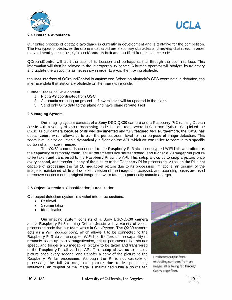
2.6 Object Detection, Classification, Localization Our object detection system is divided into three sections:
● Retrieval ● Segmentation ● Identification
Our imaging system consists of a Sony DSC-QX30 camera and a Raspberry Pi 3 running Debian Jessie with a variety of vision processing code that our team wrote in C++/Python. The QX30 camera acts as a WiFi access point, which allows it to be connected to the Raspberry Pi 3 via an encrypted WiFi link. It offers us the capability to remotely zoom up to 30x magnification, adjust parameters like shutter speed, and trigger a 20 megapixel picture to be taken and transferred to the Raspberry Pi, all via http API. This setup allows us to snap a picture once every second, and transfer a copy of the picture to the Raspberry Pi for processing. Although the Pi is not capable of processing the full 20 megapixel picture due to its processing limitations, an original of the image is maintained while a downsized

UCLA UAS University of California, Los Angeles 10
version of the image is processed, and bounding boxes are used to recover sections of the original image that were found to potentially contain a target.
The retrieval is simply a Python script that interfaces with the Sony API to manage camera zoom and shutter speed to ensure the best image is captured and transferred to the Pi for processing. Although not all images are guaranteed to be processed, all images are saved from this stage for debugging later on the camera.
The segmentation is a C++ program which, using OpenCV, dissects the latest captured image
and finds portions of the image that likely contain targets. To speed up the segmentation process, the captured image is first downsized to a lower resolution to speed up the calls to later OpenCV methods that will handle the image. Afterwards, the image is thresholded, and the image is split into three separate channels (for red, green, and blue) to ensure that all objects of different colors are found. An edge filter is then applied to each thresholded channel (Canny edge filter) to highlight the raw edges between features in the image. With an edge filter, overlapping objects like a target lying on a field of grass are traced out
and stored for use by OpenCV to extract later on. OpenCV is then used to extract these contours from all three channels, and the results are stored in a single vector. This vector is then filtered based on a variety of fixed criteria to remove contours that are very likely not to closely trace out a target. This filter is based on area (to filter out small patches of field that were detected), aspect ratio (to eliminate things like a large, skinny runway that may have been captured), and color (to ensure that the contours are close to a pure color, instead of a patch of grass that has many shades of various colors). Finally, bounding boxes are generated around the remaining contours (ensuring that overlapping boxes are combined), a small amount of padding is added around the contour, and the bounding boxes are mapped to the original image to create high quality masks of the potential targets. These targets are then stored, and the segmentation program processes the latest image taken by the camera.
To identify the shapes of the targets extracted in the segmentation stage, all of the masks of the contours found are fed through a convolutional neural network (CNN). We chose to use TensorFlow as the framework for this stage since it is one of the newest, most actively developed projects in the field of image recognition at the moment, and provides a lot of online documentation to train new users of the platform. On top of TensorFlow, we used the Inception TensorFlow model to provide a basis for the training and identification process. This allowed us to build upon a model that was already partly trained, and only required us to train the final layer by plugging in examples of the targets that we wanted to identify for our project. To generate the images for training, we used a combination of synthetically-generated images of a field containing targets, hand-picked images from the internet of targets from past AUVSI SUAS competitions, and examples from our own flights. Over the next quarter, this training set of images will be built upon to improve our shape detecting neural network and improve the accuracy of the results from this stage. With the generated model, a Python script is used to process the contour masks generated by the segmentation program and generate a list of percentages that quantify the confidence that the neural network has for the contour being each specific shape. These percentages are thresholded, to eliminate false positives of images that do not contain any targets. If the image does contain a contour, a JSON file is generated containing all the information that was collected about the target (including information about the primary color, which is determined using a color intensity histogram only for contours that are found to contain a target).

UCLA UAS University of California, Los Angeles 11
2.7 Communications
Communications System Flow Chart.
Pilot RC controls for manual takeoff and landing, and emergency overriding are sent by the pilot
radio on the remote control up to the tranceiver on the plane. These are sent as typical pitch/yaw/roll control surface inputs to the Pixhawk, which then relays communications to the plane. In fly-by-wire testing, this same communication line is used, except the pilot’s control stick inputs represent pitch yaw and roll positions which the plane is to try and hold. Flight mode is also toggled by the radio control.
Communications with the MAV are carried over a MAVLink datastream. Telemetry data acquired and used by the pixhawk is read by the Raspberry Pi over a UART connection. MAVProxy, running on the Raspberry Pi is used forward MAVLink packets over another UART connection to our telemetry radio. This way, the Raspberry Pi is able to intercept MAVLink packets for use in tagging recognized ground objects with GPS data. The telemetry radio then is connected to the radio on our ground station, which is connected by a usb serial connection to our ground station computer. On the ground station computer, MAVProxy is used again, this time to split the datastream into two data streams: One stream to be fed into the interoperability client, for inserting into JSON objects for the Interoperability server, the other stream to be fed into QGround control, which acts as our user interface for tracking the Plane’s movement and planning and uploading routes.
We modified the provided interop_cli.py to use the AsyncClient API and used it to translate the MAVLink stream to JSON format and transmit it to the judges’ server. Our interoperability system uses the Python interoperability client library to handle communications between the ground station and the judges’ server. The AsyncClient API was chosen because its multithreaded functionality improves system performance. The system consists of a Python script that launches other programs as background processes, so the system can operate autonomously after it is initiated with a single command.
The script also communicates with the server to request data on obstacle positions and dimensions. Currently, this data is output to the command line, and ground station operators set waypoints that avoid those positions. In the future, we will attempt to modify qGroundControl to display the obstacles on screen to make routing easier.
UCLA UAS University of California, Los Angeles 12
Currently, classified object data is stored on the Raspberry Pi’s SD card in json format. Upon landing, it can be extracted and passed to the interoperability client for uploading to the judging server. We are now attempting to send this object detection data over the MAVLink data stream, so that the image submission will also be entirely hands off. 2.8 Air Delivery Because this is the first year that our UAS is flying in competition, the team is more focused on producing an aircraft that flies autonomously, can take images and recognize them, and avoid obstacles in the field. At the time of this report, the payload system has not been constructed and only is in the design phase. Several experiments were carried out regarding the delivery of the payload to the ground. However, due to time and physical constraints of the team and UAS respectively, air delivery might not be executed during the competition. At this time the plans are to have a water bottle contained in a foam casing that is ejected from the plane using a servo and spring. Hopefully this method will be implemented in the following weeks or at a future competition. 2.9 Cyber Security
Cyber Security was not directly addressed in our system. Some of our electrical components do have built in security measures.
3) Test and Evaluation Plan 3.1 Developmental Testing (By Stages) Secondary Airframe Testing
Initial test flights were conducted on a smaller, simpler, and less costly airframe. These flights were meant primarily to familiarize the team with the Pixhawk Mini. To conduct these tests, a second, simpler airframe was used. After our pilot was comfortable flying the airframe, the pixhawk mini was set to hold its direction. Primary Airframe Testing
After our larger airframe was assembled, flights were conducted so that our pilot could familiarize himself with the unconventional ruddervator. The autopilot system was also reconfigured and had to be tested. To make sure that the ruddervator mixing was correctly implemented. So again, the plane was flown manually, to hold its direction, and then set to Fly-By-Wire mode. In Fly-By-Wire mode, the plane would maintain its direction, but accept pilot roll input as command input. In other words, while usual control stick inputs determine control surface positions, in this mode, control stick inputs represent roll angles the plane would attempt to maintain. Subsequent flights were used to test different aspects of our design in parallel. Navigation
A set of waypoints was loaded onto the Pixhawk Mini, and the plane’s ability to pilot itself was tested on two separate flight days. Two flights were also conducted in which the set of waypoints that the plane was following was updated and reloaded mid-flight. The repeated testing allowed for the plane to be flown in both significant and insignificant wind. Imaging These tests were conducted on the Primary Airframe in parallel with our navigational testing, because our cameras were too large for our Secondary Airframe. Initially, a GoPro Hero 3 was mounted onto the plane pointed straight forward. A video was recorded using only the GoPro’s built in recording
UCLA UAS University of California, Los Angeles 13
functionality to assess the camera’s lower resolution capabilities and to provide potential debug data for navigation tests. Afterward, the camera was pointed straight down, and pictures were taken using the GoPro’s built in timed capturing at its highest possible resolution. Mock ground targets were placed on the test airfield, and navigational waypoints were placed to route the plane over these targets. After these images were recovered, it was determined that the focal length of the lens used was not enough.
On the next flight, a telephoto lens was attached to the GoPro, and in this test, a raspberry pi 2 was added to the plane, to use the GoPro’s wifi api to trigger and manipulate image data in anticipation of conducting recognition tests. Duration The number of LiPo batteries used in the tests was varied, as progressive flights demanded longer and longer flight times. We have tested with 1 and 2 batteries, and have achieved 15 and 30 minutes of sustained flight before battery meters indicated 25% of expected battery life (as measured by a voltmeter based indicator adjusted to read 0% at 14.4V and 100% at 16.8V.) 3.2 Individual Component Testing
Electrical components needed to be tested throughout the season as parts were added to the power system incrementally to ensure the power loads placed on the electrical system were manageable. First, only the ESC, and one BEC were placed in the plane, delivering power to the motor and to the control servos and RC tranceiver respectively. This was used for our manual control only airframe testing. Then, the Pixhawk’s power distribution board was used to add a separate power line to the system, which the pixhawk and its peripherals was attached through. Next, the power lines were tested again when the second BEC, raspberry pi, uart module module, telemetry radio, and camera were added.
The Sony QX30 was a recent addition. To make the decision to move to a more expensive camera from the GoPro Hero 3 that was available to the club, we conducted stationary testing with the GoPro, by taking pictures from a building of height similar to our flight altitudes (~150 ft) of mock ground targets. It seemed that in flight, the image quality would not be sufficient, so a magnification lens was ordered, while test flights verified our expectation of the GoPro’s performance. Images were taken from the same building to evaluate the GoPro with the lens and the Sony Camera. Additionally, vibration testing was conducted for the Sony Camera, by running the motor on the ground and recording video. 3.3 Mission Testing Plan
Our UAS was subjected to many tests flights over the course of the design process. The first few tests were conducted in order to make sure that the plane can be flown by a pilot easily and with few errors. At first, a professional RC pilot at an airfield was used and then a designated member of the team. These few tests allowed us to determine equipment issues before the autopilot was utilized. Next, the autopilot was tested on a smaller RC plane so that issues with the autopilot could be determined without the risk of destroying the competition plane. The tests were simple at first, requiring the autopilot to control stabilization and altitude and eventually moved onto autonomous flight with waypoints. The autopilot was then moved to the competition plane and tested to make sure it behaves similarly to the test plane. After this, the focus was placed on getting the image recognition system up and running as well as fine tuning the plane and carrying out secondary tasks. The length of time in between these tests ranged from every few weeks in the beginning to almost every weekend during the last few weeks of the design process.
4) Safety, Risks, and Mitigations 4.1 Developmental Risks & Mitigations
Three big risks that are associated with any group project are total time spent on the engineering part of the project, errors caused during testing that may compromise the project, and budget considerations that determine the amount of leeway that a team has when faced with a time crunch.
Since this UAS was developed during the school year, team members were faced with the challenge of balancing schoolwork with time to design and build the drone. To ensure that all members were able to contribute as much as they could to the project, we divided projects for the plane into smaller groups (AI for vision and controls, and structures for the actual build of the plane) and allowed those

UCLA UAS University of California, Los Angeles 14
groups to individually communicate and schedule smaller meetings over Slack, our main team communication network. At our Thursday general meetings, we were then able to sync up between all of these groups and ensure that deadlines were being met while team members were still able to complete their schoolwork and also handle other outside activities.
For testing, it was very important that our team took great care whenever flying the competition drone, or risk having to spend valuable resources rebuilding the drone from scratch in the event of a crash. As stated earlier in this report, we had a human operator who always had control of the drone to prevent crashes due to the autonomous system. In addition, we had a well-trained pilot who monitored the student pilot on hand in case the student pilot had trouble recovering the drone from a nosedive. Due to the construction of the drone, a medium crash of the drone would most likely only damage the outer body since the padding of the foam provided cushioning for the internals. Since this foam body is readily available online for purchase, most crashes that our team ran the risk of encountering would only result in a small toll on our budget. Finally, our team raised enough money this year to fund our UAS build and still have enough left over for a contingency budget in the event that a much more powerful computer was needed later on, a drone crash called for new expensive internal components, or any other cost was encountered by our team that was not predicted in advance. With this spare money as a form of insurance for our drone, we mitigated the risk of losing our chance of qualifying due to lack of funds to purchase the replacements we would need to repair our drone, in the event that such repairs were needed. Although our team, for the most part, has not yet faced any serious issues that would require this emergency fund of money (up to about $1,500), we have kept it around throughout our build season as assurance that we could handle such issues. 4.2 Mission Risks and Mitigations Faulty Connections
Poor or faulty connections in the electrical system of the aircraft can go unnoticed or put off as a problem in need of solving if intermittent. Therefore it is necessary to address any potential electrical problems before they occur by careful assembly of the electrical framework through proper soldering techniques, peer review of electrical assembly, careful documentation of procedure for connecting components, and detailed log of issues in the system to be addressed in group meetings. Motor/ESC failure
To mitigate the effect of potential engine or ESC failure mid-flight we tested out our initial flight vehicle (without our autopilot/image recognition system) through an hour of strenuous flying at three different types of flying: at the plane’s critical stall speed, at a mid-range speed for comfortable flying, and at full throttle, each of which lasted ten minutes. This enabled our team’s pilot to get a sense of the plane’s maneuverability as well as put the plane’s basic flight system (motor, esc, battery, and servo) through its paces. Additionally, we tested the plane on the ground through the throttle range with an attached meter to measure the current draw and power consumed at the three throttle locations. At this stage, we were able to rule out any factory defects of the motor and ESC, however to decrease the chance of a catastrophic crash resulting from an unexpected loss of the ESC or motor during flight. We devised a separate electronic system to power the receiver, autopilot, and image recognition system isolated from the system supplying power to the motor. Flying While at Critical Voltage
Flying at low power presents the risk of losing all ability to fly if energy is unavailable to drive the motor. To mitigate this, two BECs and a separate power distribution board are used as extra power lines in case the power line to the motor cuts out. In addition, battery voltage is included in the telemetry data stream sent back to the ground station computer. Unbalanced Aircraft With Shifting Mass
Due to the unstable nature of RC flight, we expect the internal contents of the UAS to be subject to movement. For this reason, we have properly secured the electronics, batteries and other equipment so that this cannot happen. Before things were secured, the internals were placed in the aircraft and were

UCLA UAS University of California, Los Angeles 15
arranged so that the plane balances at its correct center of gravity. The center of gravity was shifted slightly forward as well, so in the case of equipment failure the plane will go into a nosedive instead of a tail dive. Then, the parts were secured with adhesives so that they are not able to move in any direction during flight. Glues and epoxies were used on equipment that does not need to be moved and for things that must be removed periodically, like the camera and batteries, we use velcro so this can be done easily. When new internals are added throughout the design process, the internals are rearranged so that the plane balances correctly with respect to its center of gravity. Weather
Our UAS is expected to perform under a wide range of weather conditions, from high winds and rain to optimal flying conditions. Since our drone does contain many highly sensitive electronic devices that are crucial to our success, much attention was paid to the make sure that these are protected from the environment. All of our electronics remain inside the plane with the exception of our camera lens, wing servos, antenna, and GPS to prevent damage from external conditions. As mentioned previously, all these items are properly secured so that high winds and unexpected turbulence do not affect the operation of the drone. Hard Landings
Since the plane will take off and land autonomously, there is a chance of a hard landing subjecting the plane to many stresses not present during flight. For this reason, we have designed the plane so that most of the internals are inside the plane and secured properly. We have also mounted the camera inside the plane so that the only part that extends outside of the fuselage is the lens of the camera. When this is not needed (ie. during takeoff and landing) the camera lens can retract into the body of the plane, preventing it from being damaged during a hard landing. The plane is also composed of foam, which fares better under a hard landing. Transportation & Storage
Since our UAS was once part of a kit, it can be taken apart and put back together fairly easily. For this reason, we store and transport our plane in separate parts to prevent damage. These parts include the fuselage (which contains all of the internal electronics and motor), the wings, and the rudder, requiring the plane to be assembled before each use. Since the plane must be reassembled, this creates the risk that it is not assembled correctly before flying. To prevent failure during flight, the plane is thoroughly inspected and tested beforehand to makes sure all of the components of the UAS work properly and together. This prevents any issues that may arise from improper assembly. 4.3 Operational Risks and Mitigations Interference Testing and Elimination
The motivation to introduce and perform rigorous interference testing was our experience with crashes during test flights over the past two years. In one of the previous years, during a manual test flight, our plane ran into external interference from other sources at the RC airfield. We zeroed in on the cause of the crash being our use of a 72MHz transmitter. The U.S. has dedicated bands for RC aircrafts in and around the 2.4GHz range whereas a lot of radio, TV and other common communication takes place at 72MHz resulting in the UAV receiving inputs from these random sources. So we switched from a 72 MHz to a 2.4 GHz controller to counteract this problem.
In addition, we also performed a range test. For this we took the controller away from the airplane and checked how far we could go before the control surfaces didn’t respond as expected. The distance was found to be approximately 700m, which suffices for our competition needs. Once we determined that the controller range was as desired we went ahead and approved the use of the controller for all test flights. Further, the controller chosen was a Spektrum DX7S. It offers a feature called Digital Spectrum Modulation.
Our telemetry radio, the RFD900x employs Frequency Hopping Spread Spectrum (FHSS)

UCLA UAS University of California, Los Angeles 16
technology. In FHSS the controller makes jumps in frequency thus transmitting data at different frequencies within a given band. The controller transmits at one frequency for a set period of time (usually at the order of milliseconds) and then switches to another frequency within the band. As a result the chances of interference from another source transmitting at a particular frequency is considerably reduced.
To eliminate interference with the GPS signal we isolated the GPS from the other electronic components in the fuselage. We also kept the wire and cable runs away from transmitters and antennas in the plane.
We used shielding for the cable/wire runs and enclosures for sensitive electronics. The autopilot board and GPS were mounted on vibration-dampening materials in order to reduce their effect on the accelerometers. All coaxial cables had soldered connectors and heat shrink tubing as opposed to crimping which our team has done in the past. The two antennas for RC control and telemetry radios were positioned as far apart from each other as possible. Additionally the Receiver and it’s satellite antennas were positioned at right angles to reduce the chances of losing contact with the plane during flight which can occur if the antennas are parallel to the light of sight of the aircraft.
A possible addition to our plane is adding a grounding system for the onboard electronics. This can be done by using copper shielding from large coaxial cables and placing the shield over the cable runs and then grounding the shield.
5) References
1. https://www.readymaderc.com/store/index.php?main_page=product_info&cPath=112_40
9_410&products_id=3239
2. http://diydrones.com/profiles/blogs/new-3dr-autopilot-pixhawk-mini-2
3. https://www.amazon.com/Raspberry-Pi-RASPBERRYPI3-MODB-1GB-Model-
Motherboard/dp/B01CD5VC92