technical explanation for inverters...technical explanation for inverters sensors switches safety...
TRANSCRIPT

SensorsSwitches
Safety Components
RelaysControl Com
ponentsAutom
ation Systems
Motion / Drives
Energy Conservation Support / Environment Measure Equipment
Power Supplies /In Addition
OthersCom
mon
1
CSM_Inverter_TG_E_1_2
Technical Explanation for Inverters
IntroductionWhat Is an Inverter?An inverter controls the frequency of power supplied to an AC motor to control the rotation speed of the motor.Without an inverter, the AC motor would operate at full speed as soon as the power supply was turned ON. You would not be able to control the speed, making the applications for the motor limited. The use of an inverter to adjust the speed and acceleration of an AC motor increases the range of applications of the motor compared with a motor that operates at a constant speed. The speed of a motor is normally measured as the number of revolutions per minute (rpm). The acceleration rate is given as the change in speed over a specific period of time.
FeaturesFreely Set and Change AC Power Frequency and VoltageAn inverter uses this feature to freely control the speed and torque of a motor.
This type of control, in which the frequency and voltage are freely set, is called pulse width modulation, or PWM. The inverter first converts the input AC power to DC power and again creates AC power from the converted DC power using PWM control. The inverter outputs a pulsed voltage, and the pulses are smoothed by the motor coil so that a sine wave current flows to the motor to control the speed and torque of the motor.
The voltage output from the inverter is in pulse form.The pulses are smoothed by the motor coil, and a sine wave current flows. As a result, the output from a general-purpose inverter cannot be used for equipment other than motors.
PrinciplesControl ModesV/f ControlV/f control is a method of controlling a motor by supplying a specific current to the coil to output a specific torque. Therefore, the voltage and frequency are in a proportional relationship. This is called the V/f characteristics.
Vector ControlVector control is used to correct the output waveform according to the voltage and current output from the inverter to an induction motor. The motor speed and output torque are estimated from the voltage and current output to control them.Although induction motors have unstable characteristics, the use of vector control produces stable characteristics where the actual speed can follow a reference frequency in the same way as a servomotor.There are mainly the following two types of vector control.
Sensorless Vector ControlSensorless means that there is no feedback from an encoder. Although there is no feedback signal from a sensor, the current and voltage output from the inverter to the motor are used to correct the output waveform. This enables finer speed control.
+
Fixed frequency (50/60 Hz)
Capacitor (smoothingcircuit)
Rectifier(converter)
Power supply
PWM control
Inverter unit
Inverter
Requiredfrequency
Motor
Vol
tage
Frequency
V/f Characteristics

Technical Explanation for Inverters
2
SensorsSwitches
Safety Components
RelaysControl Com
ponentsAutom
ation Systems
Motion / Drives
Energy Conservation Support / Environment Measure Equipment
Power Supplies /In Addition
OthersCom
mon
Vector Control with Encoder FeedbackAs opposed to sensorless vector control, control is performed using feedback from an encoder.The encoder is also called a pulse generator, and this type of control is also called vector control with PG.
With this method, the inverter monitors the output voltage, the output current, and the encoder feedback from the motor. The encoder feedback is used to adjust the output waveform to perform precise speed control.
Main Basic FunctionsApplicable MotorsOmron inverters can control induction motors. Omron also provides inverters that can control synchronous motors.
As induction motors can be used to achieve simple speed control at a relatively low cost, they are used in many applications. They can be operated just by connecting an AC power supply, so installation is extremely easy. Generally, a cooling fan is attached to the back to help dissipate heat generated by the motor.
Torque Boost (Torque Compensation)In low-frequency ranges, voltage drop has a large impact, reducing the motor torque. To compensate for this, adjustments are made to output a high voltage at the required frequency. This function is called torque boost or torque compensation. Two torque boost options are available: Manual torque adjustment and automatic torque adjustment.
Inverter Overload DetectionThere are two types of overloads with an inverter: inverter overload and motor overload. Overload detection is performed to protect both the inverter and motor from burning.
Inverter Overvoltage Detection and Braking FunctionWhen a motor decelerates, or when the load descends, the motor serves as a generator to feed back the energy to the inverter. This phenomenon is known as regeneration.If the regenerative energy is too large to be stored in the inverter, it causes an overvoltage.Regenerative processing uses the braking circuits built into the inverter to convert the regenerated energy into heat via resistors, preventing an overvoltage.
EncoderMotor
Motors
DC motors
AC motors
Synchronous motors
Commutator motors
These motors can be controlled withOmron inverters.
Three-phase induction motors
Single-phase induction motors
Used in electric drills, vacuum cleaners, mixers, etc.
Induction motors
General-purpose business and consumer applications (printers, copy machines, radio-controlled model cars, toy robots, etc.)

Technical Explanation for Inverters
3
SensorsSwitches
Safety Components
RelaysControl Com
ponentsAutom
ation Systems
Motion / Drives
Energy Conservation Support / Environment Measure Equipment
Power Supplies /In Addition
OthersCom
mon
Explanation of TermsPerformanceOutput VoltageThe voltage between the output terminals of an inverter.
Maximum VoltageThe maximum value of a voltage equivalent to the effective value that an inverter can output at the rated input voltage.
Output CurrentThe current that flows at the output terminals of an inverter.
Output FrequencyThe voltage frequency between the output terminals of an inverter.
Braking ResistorAn external resistor that is connected to an inverter to absorb the regenerative energy generated when a load decelerates or an elevating axis descends.This resistor prevents overvoltage trip of the inverter.
Regenerative Braking FunctionThe regenerative braking function uses the built-in or an external regenerative braking circuit to decrease the internal DC voltage of the inverter by converting the regenerated energy from the motor into heat via external braking resistors.This function is enabled only when the inverter is connected with one or more external braking resistors/external regenerative braking units.
Regenerative EnergyA load connected to a motor has kinetic energy while it rotates and has potential energy while it stays in a high position. The energy that returns to an inverter when a motor decelerates or a load descends.This phenomenon is known as regeneration, and the energy is called regenerative energy.
Noise FilterA high-frequency filter that is connected to the power supply side or load side of an inverter to absorb noise that is generated in an inverter when a power device switches.
Cooling FanA fan used to cool heating components, such as semiconductors, in the main circuit of an inverter.
ReactorA reactor is used to suppress harmonics generated from an inverter.There are DC reactors and AC reactors. Both of them work to suppress rapid changes in the current.
HarmonicsThe current distortion from the normal current sine wave generated when AC is converted to DC and then smoothed.Inverters generate harmonics, which can affect electrical equipment and peripheral devices.
FunctionsSpeed Control (ASR)A function that controls the rotation speed of a motor. (Automatic Speed Regulator)
Control ModeA method to control the motor speed with an inverter including V/f control, vector control, etc.
V/f Control and V/f CharacteristicsA method and characteristics of controlling a motor by applying a specific current to the coil to output a specific torque.Refer to Principles for details.
Constant Torque CharacteristicsThis setting enables the output of a constant torque based on the frequency, according to the V/f characteristics that represent the proportional relationship between the output frequency and the output voltage.However, the output voltage is proportional from 0 Hz to the base frequency, it is constant independent of the frequency, from the base frequency to the maximum frequency. This setting is suitable for cart, conveyor, overhead traveling crane, and other applications where a torque is required, independent of the motor rotation speed.
Reduced Torque CharacteristicsThis setting is suitable for fan, pump, and other applications that do not require large torque at low speeds.It provides high efficiency, reduced noise, and reduced vibration, because the output voltage is reduced in the low speed range.
Special Reduced Torque Characteristics (Squared Reduced Load Torque Characteristics)Characteristics that are virtually constant with the square of the speed (i.e., characteristics at which the torque generation curve is a square curve) and require a large torque at low speeds.
Base FrequencyThe maximum frequency at which a motor can generate the rated torque continuously. An inverter has 50 Hz or 60 Hz as its base frequency.
Vector ControlA control method that corrects the output waveform according to the voltage and current output from the inverter to an induction motor.Refer to Principles for details.
Sensorless Vector Control (Vector Control without PG)Vector control with no feedback from an encoder.Refer to Principles for details.
Vector Control with PGVector control with feedback from an encoder.Refer to Principles for details.

Technical Explanation for Inverters
4
SensorsSwitches
Safety Components
RelaysControl Com
ponentsAutom
ation Systems
Motion / Drives
Energy Conservation Support / Environment Measure Equipment
Power Supplies /In Addition
OthersCom
mon
Acceleration TimeThe time required for the output frequency to go from 0 Hz to the maximum frequency.
Deceleration TimeThe time within which an output frequency is reduced to 0 Hz from the maximum output frequency.
Starting FrequencyThe frequency at which the inverter starts its output when the RUN signal turns ON.
Maximum FrequencyThe maximum value of the frequency that an inverter can output.
Minimum Output FrequencyAn output frequency shown when the minimum value of a frequency setting signal is input (e.g., 4 mA for 4 to 20 mA input).
Zero SpeedThe condition when the frequency is lower than the minimum output frequency.
Carrier FrequencyA frequency that determines the pulse-width-modulation cycle.Set a higher carrier frequency value to reduce the metallic noise generated by the motor.
Torque ControlA control method that enables the torque generated by a motor to be equal to a torque reference input.
Starting TorqueThe torque that is output when the motor starts.The motor will not rotate if a load larger than this torque is applied to the motor.
Torque LimitA function that limits the output torque of a motor.
DC BrakingA function that applies a DC voltage to the induction motor for braking control (i.e., firmly stops motor rotation).The function operates either when the motor starts or stops.• DC Braking at Startup:
DC braking is used to stop the motor rotating by inertia without regenerative processing before starting it.
• DC Braking at Stopping:DC braking is used if the load is large or if it will rotate by inertia and not stop with normal deceleration.
TrippingTurning OFF the power supply from the inverter to the motor by operating the protection function of the inverter against overvoltage, overcurrent, or other factors.
Fault RetryA function that automatically restarts a tripped inverter.
Stalled StatusThe status in which the rotor at the motor stator cannot follow the rotating magnetic field because the load applied to the motor is too large or the acceleration or deceleration is too rapid.The motor loses speed or will be out of step.
OvercurrentThe status in which a larger current than the rated output current flows in the circuit.
Overcurrent Suppression FunctionA function that suppresses the overcurrent caused by a steep current increase due to an impact load etc.It causes the inverter to stop accelerating when the output current reaches a certain percentage of the rated current.
OvervoltageThe status in which more than the rated voltage is applied to a circuit.
Overvoltage Suppression Function during DecelerationA function that prevents overvoltage trip caused by the regenerative energy from the motor during deceleration.Two options are available: Automatic deceleration while keeping the voltage rise at a certain level and starting acceleration when the voltage rise exceeds a certain level.
UndervoltageA status in which the power supply voltage is below the rated value.
OvertorqueA status in which the output torque is higher than the rated value.
Overtorque DetectionA function that detects that the estimated motor output torque value exceeded the set level and output the overtorque signal.
Undertorque DetectionA function that detects that the estimated motor output torque value fell below the set level and output the underorque signal.
Electronic Thermal FunctionA function that prevents a motor from overloading and burning.
Motor OverloadThe status in which a load that is higher than the rated torque is applied to a motor.
Inverter OverloadThe status in which the inverter overload protection has been operated by an electronic thermal.
Motor ProtectionA function that enables an inverter to internally have the characteristics data of the motor and to internally perform calculations during operation to protect the motor.

Technical Explanation for Inverters
5
SensorsSwitches
Safety Components
RelaysControl Com
ponentsAutom
ation Systems
Motion / Drives
Energy Conservation Support / Environment Measure Equipment
Power Supplies /In Addition
OthersCom
mon
Input Phase LossA function that detects phase loss in the input power supply.Detection is performed using the fluctuation in the main circuit's DC voltage. Detection can thus also be performed using the power supply fluctuation and unbalance or degradation in the main circuit capacitor.
Output Phase-loss DetectionA function that detects phase loss in the inverter output terminals. Detection is performed using the values of the currents flowing at the output phases.
Drive ModeA mode in which operation commands can be received.
Digital OperatorA unit used to operate an inverter and provide display.A digital operator can be removed from the inverter body and installed on a control panel. It can be also used for remote control.
Frequency ReferenceA reference provided by the frequency of the power supply to a motor.
Analog ReferenceA frequency reference of an inverter that is set with an analog signal.Analog signal: A signal that expresses continuous quantities through the size of the signal. 0 to 5 V, 0 to 10 V, 4 to 20 mA, etc.
STOP CommandA command that stops a motor via an inverter using the digital operator or a contact input.It enables either a free-run stop or a deceleration stop.
Deceleration StopA function that decelerates a motor at a certain ratio until the motor stops.
Free-run StopA method of shutting off the inverter output to stop the motor rotation.Executing the free-run stop function causes the motor to fall a free-run state, in which it decelerates due to the load and friction forces exerted on the motor and/or machine and comes to a stop.
Multi-function InputThe functions, such as RUN commands and STOP commands, can be allocated to the multi-function input terminals to use them.
Multi-function OutputThe functions, such as a signal during RUN, can be allocated to the multi-function output terminals to output signals.
AVR (Automatic Voltage Regulator) FunctionA function that has the inverter automatically compensate for the output voltage to the motor even if the incoming voltage fluctuates.It is useful as a preventive measure against low output torque to the motor or overexcitation.Note, however, that the inverter cannot output voltage exceeding the incoming voltage to the inverter.
Multi-step Speed OperationA function that sets RUN speeds using multi-step speed references and switches the set speeds via external signal input.
Jogging OperationA function that allows you to determine and fine-tune the motor stop position.
PID ControlA control method that matches a feedback (detected) value to a set target value by combining proportional (P), integral (I), and derivative (D) operations that control the flow rate, air volume, pressure, and other processes.• Proportional (P) Operation:
In this operation, the control volume is proportional to the deviation (difference between the target value and the current value).
• Integral (I) Operation:In this operation, the control volume is proportional to the time integral value of the deviation.The P operation is less effective as the current value approaches the target value due to smaller deviation, taking a long time to reach the target value. The I operation compensates this disadvantage.
• Derivative (D) Operation:In this operation, the control volume is proportional to the percentage of change in the deviation.Because using only the PI operation is time-consuming, the D operation is used to effectively compensate for the disadvantage in responsiveness.
Auto-tuningA function to automatically measure and record the circuit constants of a motor, including the constants of motor coil or amount of moment of inertia.Auto-tuning is generally used for vector control.There are two measuring methods: measurement using a rotating motor and using a motor that does not rotate.
Jump FrequencyA frequency that is set to maintain a stable output by not changing the output frequency to within a specified frequency zone and thus avoid a resonance frequency of a machine.
Restart During Momentary Power InterruptionA function that allows selecting tripping or retrying (i.e., restarting) when the power is momentarily interrupted or there is an undervoltage.
Torque BoostA function that raises the output torque if it is not sufficient at low speeds.The inverter provides two torque boost options: Manual torque boost for manual torque adjustment and Automatic torque boost for automatic torque adjustment.
Automatic Torque BoostA function that automatically controls the output voltage by detecting an output current of an inverter to increase the torque when it is insufficient at low speeds.

Technical Explanation for Inverters
6
SensorsSwitches
Safety Components
RelaysControl Com
ponentsAutom
ation Systems
Motion / Drives
Energy Conservation Support / Environment Measure Equipment
Power Supplies /In Addition
OthersCom
mon
Automatic Energy-saving Operation FunctionA function that automatically adjusts the inverter output power to a minimum during constant speed operation.This is suitable for the load of reduced torque characteristics, such as a fan and pump.
Brake Control FunctionA function that allows the inverter to control the external brake (non-excitation electromagnetic brake on an induction motor) of equipment, including an elevating system.
RUN Direction Limit SelectionA function that limits the RUN direction of the motor.(Generally, when viewed from the shaft, the forward rotation is defined as the direction in which the motor rotates counterclockwise and the reverse rotation as the direction in which the motor rotates clockwise.)
Speed LimitControlling the rotation speed of a motor.
Speed DeviationThe difference between the value of a set speed and the rotation speed of a motor.
Slip CompensationA function that calculates the output torque from the output current to compensate the output frequency.
Torque CompensationA function that increases the output torque when an increase in the motor load is detected.
Torque Compensation LimitA limit that restricts the torque during vector control if the maximum motor torque is insufficient or to prevent outputting excessive torque.
OthersInduction MotorA motor that rotates a rotor by means of electromagnetic induction. An induction motor uses AC to supply current to the inner coils of the motor.
Number of Motor PolesThe number of magnetic poles in a motor.It is equivalent to the number of magnetic poles wound on the shaft generating torque.
Motor RatingsThe limit within which a motor can be used under specified conditions. The motor ratings include the current, voltage, torque, etc.
Braking TorqueThe torque that operates in the direction that prevents motor rotation.
Output TorqueThe output torque of a motor. That is the moment of force generated by the rotating shaft.
Load TorqueThe torque required for the motor to operate the load.The load torque fluctuates according to the speed.
Load RatioThe percentage of load current or load torque to the rated current or torque.
Leakage InductanceA value that indicates the magnetic field that is leaked to the environment or given off as heat (core loss) without generating torque. It is usually given as the inductance (coil) component that generates the magnetic field.

Technical Explanation for Inverters
7
SensorsSwitches
Safety Components
RelaysControl Com
ponentsAutom
ation Systems
Motion / Drives
Energy Conservation Support / Environment Measure Equipment
Power Supplies /In Addition
OthersCom
mon
Further InformationMotor Capacity SelectionBefore selecting an inverter, first the motor should be chosen. In selecting the motor, calculate the load inertia appropriate to the application, and then calculate the required capacity and torque.
Simplified Selection Method (Required Output Calculation)This method of calculation helps you select a motor by calculating the output (kW) required by the motor to maintain its steady rotations. To use this method for motor selection, make allowance for the calculated result because it does not include acceleration/deceleration and other transient state calculations. The simplified selection method is suitable for fan, conveyor, mixer, and other applications where a constant state continues for a while.
The simplified selection method cannot be used for the following applications. For these applications, use the detailed selection method.• Those requiring rapid startup (acceleration)• Those that frequently repeat run and stop• Those that have a large inertia at the power transfer part• Those that have an inefficient power transfer part
For linear motion: Steady power P0 [kW]
For rotation motion: Steady power P0 [kW]
Detailed Selection Method (RMS Calculation)This method helps you select a motor by calculating the effective torque and maximum torque values required to achieve a certain pattern of operation for the application.It selects a motor that is optimal for a particular operation pattern.
Calculation of load inertia and motor-shaft conversion inertiaDepending on the type of the motor transfer system, calculate the inertia for all parts and convert it into the motor-shaft inertia.
Calculation of motor-shaft conversion torque and effective torqueCalculate the acceleration torque from the motor-shaft conversion load inertia, the motor-rotor inertia, and the acceleration. Then, calculate the load torque from the external force (gravity and tension) and friction force applied to the load. Finally, combine these calculation results to calculate the torque required for the motor.• Calculation of acceleration torque
• Calculation of motor-shaft conversion load torque
W : Mass of linear motion part [kg]V : Speed of linear motion part [m/min]η : Efficiency of transfer part
Motor
η
W
V
μ : Friction coefficientμ
Motor
T
N
T : Load torque (Load shaft) [N·m]N : Rotation speed of load shaft [r/min]
η
η : Efficiency of transfer part (η 1)
JW
: Diameter of cylinder [mm]D
: Mass of cylinder [kg]M 1
: Inertia of workpiece (Shaft conversion) [k·m2]J 2
: Inertia of cylinder (Shaft conversion) [kg·m2]J1
: Mass of workpiece [kg]M 2
: Shaft conversion inertia [kg·m2]J
: Shaft conversion inertia [kg·m2]
: Inertia of cylinder 1 [kg·m2]
: Inertia of cylinder 2 [kg·m2]
: Inertia of workpiece [kg·m2]
: Inertia of belt [kg·m2]
J
J
J
J
J
2
1
3
4
: Diameter of cylinder 1 [mm]D1
: Diameter of cylinder 2 [mm]D2
: Mass of cylinder 1 [kg]M1
: Mass of cylinder 2 [kg]M2
: Mass of workpiece [kg]M 3
: Mass of belt [kg]M 4
W
W
Roller 1
Roller 2
J
M
1
J W
J 2
D2
D1
: Shaft conversion inertia [kg·m2]
: Inertia of roller 1 [kg·m2]
: Mass of workpiece [kg]
: Inertia of roller 2 [kg·m2]
: Diameter of roller 1 [mm]
: Diameter of roller 2 [mm]
J
J
M
J
D
D
W
2
1
2
1
LoadGears
Motor : Inertia of motor-side gear [kg·m2]J 1
: Number of motor-side gear teeth
Gear ratio G = Z1/Z2
Z1
: Motor-shaft conversion inertia [kg·m2]J L
: Inertia of load-side gear [kg·m2]J 2
: Number of load-side gear teethZ2
: Load inertia [kg·m2]JW
N : Motor rotation speed [r/min]
: Acceleration torque [N·m]T
: Motor-rotor inertia [kg·m2]JM
: Motor-shaft conversion load inertia [kg·m2]JL
A
A
Acceleration torque (TA)
N
Acceleration time [s]
Speed (rotation speed)
Timet
η
M
η : Efficiency of transfer part (η 1)
: Motor-shaft conversion load torque [N·m]T1
: Number of motor-side gear teethZ1
: Load torque (Load-shaft conversion) [N·m]TW
2
η: Efficiency of transfer part
Z M
Gear ratio (Speed reduction ratio) G = Z1/Z2
: Number of load-side gear teeth
Load torque (Load-shaft conversion) [N·m]
TW:
D: Diameter of cylinder [mm]
F: External force [N]
(Generally, the friction force can be calculated as below:
F=μW μ : Coefficient of friction W : Mass of motion part [kg])

Technical Explanation for Inverters
8
SensorsSwitches
Safety Components
RelaysControl Com
ponentsAutom
ation Systems
Motion / Drives
Energy Conservation Support / Environment Measure Equipment
Power Supplies /In Addition
OthersCom
mon
• Calculation of combined torque and effective torqueMotor selectionBased on the above calculation results, select the motor capacity by using the following formulae.Select the larger of the two calculated values as the motor capacity.Also, when selecting a motor, take into consideration the errors in calculation and modeling. Select a motor whose capacity is at least approximately 20% larger.
• Motor capacity conversion to effective torqueMotor capacity [kW] = 1.048·N·TRMS·10–4
N: Maximum rotation speed [r/min]
• Motor capacity required for maximum torque outputMotor capacity [kW] = 1.048·N·TMAX·10–4/1.5N: Maximum rotation speed [r/min]
Inverter Capacity SelectionSelect an inverter that can be used with the motor you selected based on the result of motor capacity selection.Basically, select an inverter which fits the maximum applicable motor capacity of the selected motor.After selecting an inverter, check if it meets the both of the following conditions. If not, select an inverter with one size larger in capacity and check again.
Rated motor current ≤ Rated output current of inverterMax. continuous torque output time for application ≤ 1 min
Note: 1. If the inverter overload capacity is 120% of the rated output current for 1 minute, check it for 0.8 minute.2. If you want to use 0-Hz sensorless vector control, need a holding torque at a rotation speed of 0 (r/min), or frequently require 150% of
the rated torque or more, use an inverter with one size larger in capacity than the one selected by the above method.
Effective torque: TRMS [N·m]
Maximum torque: TMAX [N·m] = T1 = TA + TL
[N·m]
[N·m]
[N·m]
Time [s]0
One Cycle
0
T
Time [s]
Time [s]
Time [s]
A
t 1 t 2 t 3 t 4
TL
T2T1
T3
[r/min] N
Rotation speed
Acceleration/Deceleration torque
Motor-shaft conversion load torque
Combined torque

Technical Explanation for Inverters
9
SensorsSwitches
Safety Components
RelaysControl Com
ponentsAutom
ation Systems
Motion / Drives
Energy Conservation Support / Environment Measure Equipment
Power Supplies /In Addition
OthersCom
mon
Overview of Braking Resistor SelectionRequirement of Braking ResistorIf the regenerative energy generated in deceleration or descent in an application is too large, the main circuit voltage in the inverter may increase, which results in damage to the inverter.Normally, the inverter has a built-in overvoltage protection function, which detects an overvoltage (0 V) in the main circuit to prevent inverter damage.However, because it detects a fault to stop the motor, stable and continuous operation will be prevented.Therefore, you need to use one or more braking resistors/regenerative braking units to absorb this regenerative energy outside the inverter.
What is Regenerative Energy?The load connected to a motor has kinetic energy when rotating, and potential energy when it is subject to the gravity.When the motor decelerates, or when the load descends, the energy is fed back to an inverter.This phenomenon is known as regeneration, and the energy is called regenerative energy.
Preventing an overvoltage (0 V) in the main circuit without use of braking resistorsThe following are methods to prevent the occurrence of an overvoltage (0 V) in the main circuit without connection of braking resistors.Since these methods prolong the deceleration time, check that the selected method will not cause application problems.• Enable the Overvoltage Suppression Function during
Deceleration (It is enabled by default.) (It automatically increases the deceleration time to prevent the occurrence of an overvoltage in the main circuit.)
• Set a longer deceleration time (This decreases the amount of regenerative energy per unit time.)
• Select free-run stop (This prevents the regenerative energy from being fed back to the inverter.)
Simplified Braking Resistor SelectionThis is a simple method to select an appropriate braking resistor based on the percentage of the time in which regenerative energy is produced in a normal operation pattern. Calculate the usage rate from the following operating pattern.
Inverter Load
Regenerative Energy When decelerating, the motor serves as a generator to convert the kinetic/potential energy into regenerative energy.
Kinetic energy
Potential energy
Motor
Usage rate = t/T × 100 [% ED]
: 1 cycle operation time [s]T
Tt
: Deceleration time (regeneration time) [s]t
Technical Explanation for Inverters
10
SensorsSwitches
Safety Components
RelaysControl Com
ponentsAutom
ation Systems
Motion / Drives
Energy Conservation Support / Environment Measure Equipment
Power Supplies /In Addition
OthersCom
mon
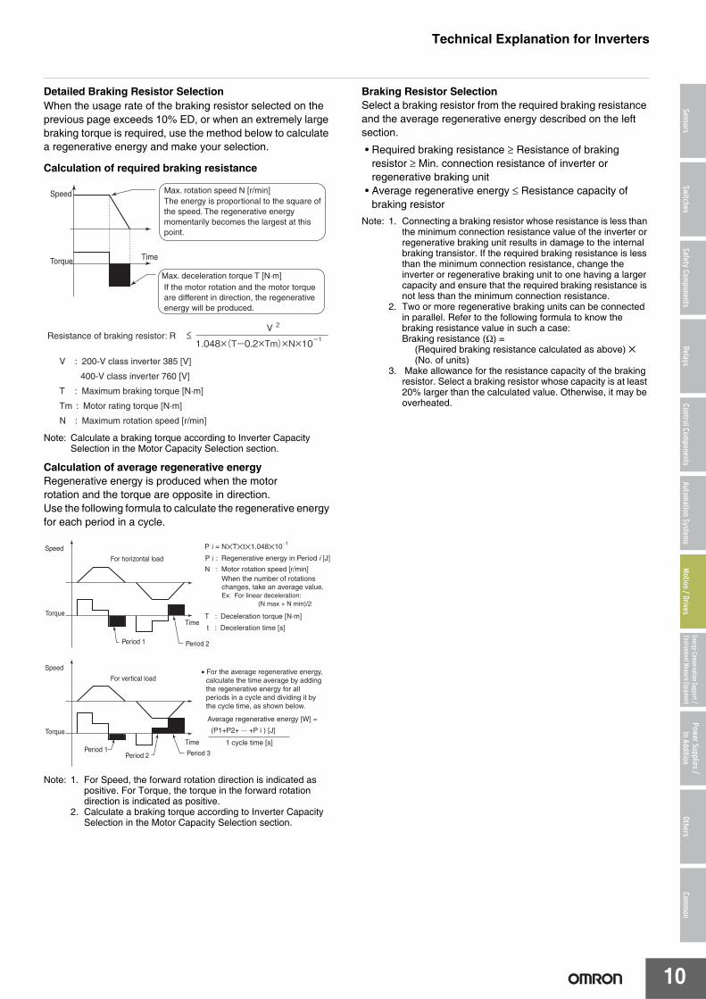
Detailed Braking Resistor SelectionWhen the usage rate of the braking resistor selected on the previous page exceeds 10% ED, or when an extremely large braking torque is required, use the method below to calculate a regenerative energy and make your selection.
Calculation of required braking resistance
Note: Calculate a braking torque according to Inverter Capacity Selection in the Motor Capacity Selection section.
Calculation of average regenerative energyRegenerative energy is produced when the motorrotation and the torque are opposite in direction.Use the following formula to calculate the regenerative energy for each period in a cycle.
Note: 1. For Speed, the forward rotation direction is indicated as positive. For Torque, the torque in the forward rotation direction is indicated as positive.
2. Calculate a braking torque according to Inverter Capacity Selection in the Motor Capacity Selection section.
Braking Resistor SelectionSelect a braking resistor from the required braking resistance and the average regenerative energy described on the left section.
• Required braking resistance ≥ Resistance of braking resistor ≥ Min. connection resistance of inverter or regenerative braking unit
• Average regenerative energy ≤ Resistance capacity of braking resistor
Note: 1. Connecting a braking resistor whose resistance is less than the minimum connection resistance value of the inverter or regenerative braking unit results in damage to the internal braking transistor. If the required braking resistance is less than the minimum connection resistance, change the inverter or regenerative braking unit to one having a larger capacity and ensure that the required braking resistance is not less than the minimum connection resistance.
2. Two or more regenerative braking units can be connected in parallel. Refer to the following formula to know the braking resistance value in such a case:Braking resistance (Ω) =
(Required braking resistance calculated as above) ✕ (No. of units)
3. Make allowance for the resistance capacity of the braking resistor. Select a braking resistor whose capacity is at least 20% larger than the calculated value. Otherwise, it may be overheated.
Max. rotation speed N [r/min]
Max. deceleration torque T [N·m]
V : 200-V class inverter 385 [V]
400-V class inverter 760 [V]
T : Maximum braking torque [N·m]
Tm : Motor rating torque [N·m]
N : Maximum rotation speed [r/min]
Resistance of braking resistor: R
TimeTorque
SpeedThe energy is proportional to the square of the speed. The regenerative energy momentarily becomes the largest at this point.
If the motor rotation and the motor torque are different in direction, the regenerative energy will be produced.
P = N�T�t�1.048�10
Time
Period 1
Period 1
Period 2
Period 2 Period 3
Time
For horizontal load
For vertical load
Torque
Torque
Speed
Speed
−1
When the number of rotations changes, take an average value.Ex: For linear deceleration: (N max + N min)/2
N : Motor rotation speed [r/min]
t : Deceleration time [s]
Average regenerative energy [W] =
T : Deceleration torque [N·m]
P : Regenerative energy in Period i [J]
(P1+P2+ ··· +P i ) [J]
1 cycle time [s]
• For the average regenerative energy, calculate the time average by adding the regenerative energy for all periods in a cycle and dividing it by the cycle time, as shown below.