technical file (tf) - tdspump.com · wetted body material: ... ds06‐axx‐xxxx‐xx,...
TRANSCRIPT
1
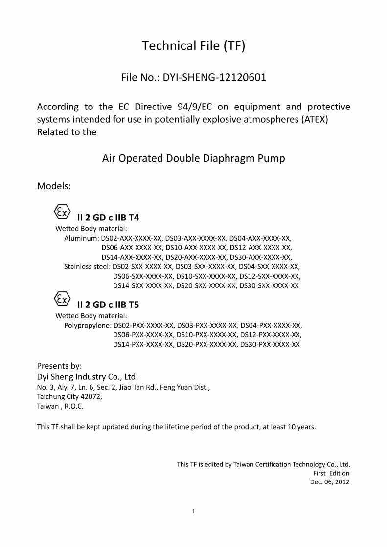
Technical File (TF)
File No.: DYI‐SHENG‐12120601
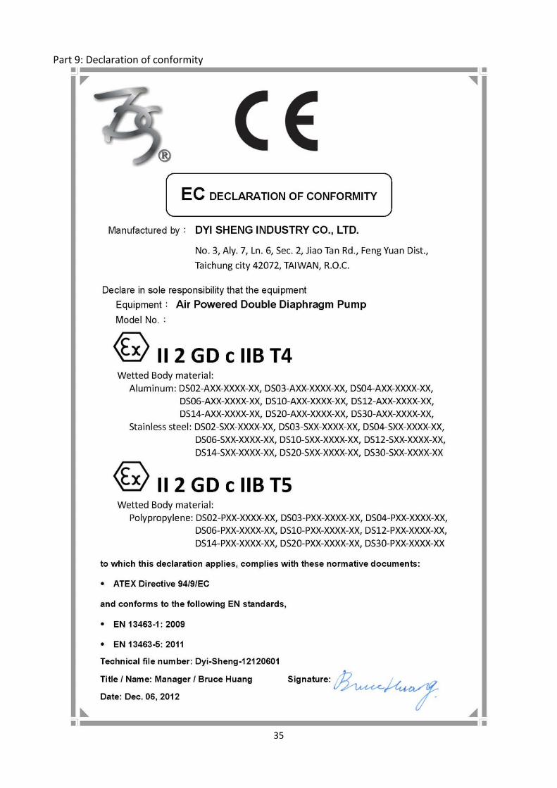
According to the EC Directive 94/9/EC on equipment and protective systems intended for use in potentially explosive atmospheres (ATEX) Related to the
Air Operated Double Diaphragm Pump Models:
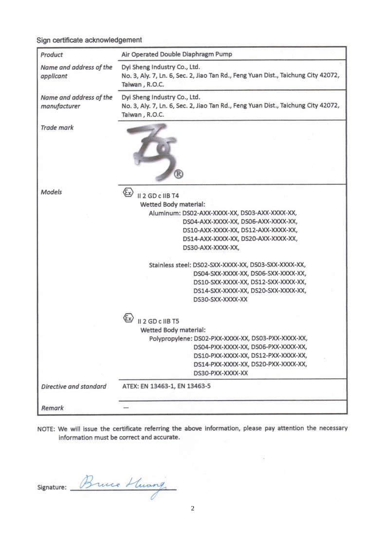
II 2 GD c IIB T4 Wetted Body material:
Aluminum: DS02‐AXX‐XXXX‐XX, DS03‐AXX‐XXXX‐XX, DS04‐AXX‐XXXX‐XX, DS06‐AXX‐XXXX‐XX, DS10‐AXX‐XXXX‐XX, DS12‐AXX‐XXXX‐XX, DS14‐AXX‐XXXX‐XX, DS20‐AXX‐XXXX‐XX, DS30‐AXX‐XXXX‐XX,
Stainless steel: DS02‐SXX‐XXXX‐XX, DS03‐SXX‐XXXX‐XX, DS04‐SXX‐XXXX‐XX, DS06‐SXX‐XXXX‐XX, DS10‐SXX‐XXXX‐XX, DS12‐SXX‐XXXX‐XX, DS14‐SXX‐XXXX‐XX, DS20‐SXX‐XXXX‐XX, DS30‐SXX‐XXXX‐XX
II 2 GD c IIB T5 Wetted Body material:
Polypropylene: DS02‐PXX‐XXXX‐XX, DS03‐PXX‐XXXX‐XX, DS04‐PXX‐XXXX‐XX, DS06‐PXX‐XXXX‐XX, DS10‐PXX‐XXXX‐XX, DS12‐PXX‐XXXX‐XX, DS14‐PXX‐XXXX‐XX, DS20‐PXX‐XXXX‐XX, DS30‐PXX‐XXXX‐XX
Presents by: Dyi Sheng Industry Co., Ltd. No. 3, Aly. 7, Ln. 6, Sec. 2, Jiao Tan Rd., Feng Yuan Dist., Taichung City 42072, Taiwan , R.O.C.
This TF shall be kept updated during the lifetime period of the product, at least 10 years.
This TF is edited by Taiwan Certification Technology Co., Ltd. First Edition Dec. 06, 2012
2
3
Contents
PART 1: GENERAL DESCRIPTION ....................................................................................................................... 4
1.1 APPLICATIONS ...................................................................................................................................... 4
1.2 PUMP TYPE SPECIFICATION INDICATION .............................................................................................. 4
1.3 SITE SELECTION .................................................................................................................................... 5
1.4 PUMP TYPE AND LIQUIDS SERVICEABILITY SPECIFICATION ................................................................. 6
1.5 MARKING.............................................................................................................................................. 7
PART 2: DESIGN AND MANUFACTURING DRAWINGS ...................................................................................... 8
2.1 PARTS DRAWING .................................................................................................................................. 8
2.2 TECHNICAL DATA .................................................................................................................................. 9
2.3 PERFORMANCE CHART ....................................................................................................................... 10
2.4 DIMENSIONS ...................................................................................................................................... 11
2.5 CHEMICAL RESISTANCE GUIDE ........................................................................................................... 13
PART 3: DESCRIPTIONS AND EXPLANATIONS NECESSARY FOR THE UNDERSTANDING OF DRAWINGS ........ 14
PART 4: LIST OF APPLICABLE DIRECTIVE AND STANDARDS ............................................................................ 14
PART 5: MATERIAL CERTIFICATES ................................................................................................................... 15
PART 6: IGNITION HAZARD ASSESSMENTS ..................................................................................................... 20
PART 7: TEST REPORTS ................................................................................................................................... 22
7.1 ROHS TEST REPORT: POLYPROPYLENE ................................................................................................ 22
7.2 RESISTANCE TO IMPACT TEST REPORT: .............................................................................................. 28
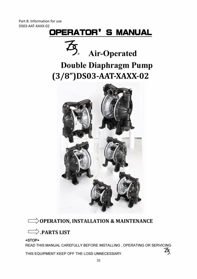
PART 8: INFORMATION FOR USE .................................................................................................................... 32
PART 9: DECLARATION OF CONFORMITY ....................................................................................................... 35
4
Part 1: General description 1.1 Applications
• Civil construction: Transmission of cement, paint, sewage, mud water, asphalt and etc. • Transmission of chemical, oil industry: Chemicals, latex, adhesives, fluxes, heavy oil, crude oil, and etc.
• Transmission of electrical, electronic industry: Resin raw materials, ceramic materials. (Through the solvents, pure water to cycle clean the parts)
• Transmission of fiber, paper, leather industry: Adhesives, glues, preservatives, pipe drainage, sludge, and wastewater treatment.
• Machinery equipment: Transmission of oil, hydraulic oil, cutting oil, electrical oil released, the cycle of release agent splash, delivery of waste oil, and etc.
• Other industries: Transmission of printing ink, glaze, clay slurry, and etc. Extraction of gasoline and motor oil.
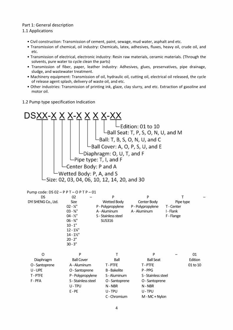
1.2 Pump type specification Indication
Pump code: DS 02 – P P T – O P T P – 01 DS 02 – P P T –
DYI SHENG Co., Ltd. Size Wetted Body Center Body Pipe type 02 ‐ ¼"
03 ‐ ⅜" 04 ‐ ½" 06 ‐ ¾" 10 ‐ 1" 12 ‐ 1¼" 14 ‐ 1½" 20 ‐ 2" 30 ‐ 3"
P ‐PolypropyleneA ‐ Aluminum S ‐ Stainless steel
SUS316
P ‐PolypropyleneA ‐ Aluminum
T ‐ Center I ‐ Flank F ‐ Flange
O P T P – 01
Diaphragm Ball Cover Ball Ball Seat Edition O ‐ Santoprene U ‐ UPE T ‐ PTFE F ‐ PFA
A ‐ Aluminum O ‐ Santoprene P ‐ PolypropyleneS ‐ Stainless steel U ‐ TPU E ‐ PE
T ‐ PTFE B ‐ Bakelite S ‐ Aluminum O ‐ Santoprene N ‐ NBR U ‐ TPU C ‐ Chromium
T ‐ PTFE P ‐ PPG S ‐ Stainless steel O ‐ Santoprene N ‐ NBR U ‐ TPU M ‐ MC + Nylon
01 to 10

5
Size
Number 02 03 04 06 10 12 14 20 30
Liquid inlet & outlet (PT) ¼" ⅜" ½" ¾" 1" 1¼" 1½" 2" 3"
Air inlet (PT) ⅛" ¼" ½" ¼" ⅜" ⅜" ½" ½" 1"
Air outlet (PT) ⅛" ¼" ¼" ⅜" ⅜" ¾" 1" 1" 1½"
Wetted Body material
P: Polypropylene A: Aluminum S: Stainless steel SUS 316
Pipe type
T: Center I: Flank F: Flange
1.3 Site selection
Self‐Priming application: Pump can operate in 1.5 to 6.5 m depth within and it changed because of temperature, pressure, liquid thickness.
Positive suction head application: Pump use this way in clean barrel through popularly. It operates useful at 0.5 to 0.8 bar for inlet pressure.
Submerged application: All pumps can operate inside the liquids. But it’s necessary to sure the outlet must exhaust outside the liquids.
6
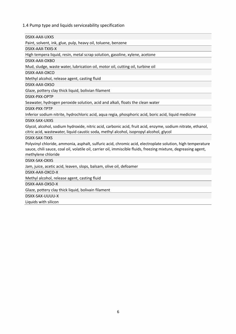
1.4 Pump type and liquids serviceability specification
DSXX‐AAX‐UXXS
Paint, solvent, ink, glue, pulp, heavy oil, toluene, benzene
DSXX‐AAX‐TXXS‐X
High tempera liquid, resin, metal scrap solution, gasoline, xylene, acetone
DSXX‐AAX‐OXBO
Mud, sludge, waste water, lubrication oil, motor oil, cutting oil, turbine oil
DSXX‐AAX‐OXCO
Methyl alcohol, release agent, casting fluid
DSXX‐AAX‐OXSO
Glaze, pottery clay thick liquid, bolivian filament
DSXX‐PXX‐OPTP
Seawater, hydrogen peroxide solution, acid and alkali, floats the clean water
DSXX‐PXX‐TPTP
Inferior sodium nitrite, hydrochloric acid, aqua regia, phosphoric acid, boric acid, liquid medicine
DSXX‐SAX‐UXXS
Glycol, alcohol, sodium hydroxide, nitric acid, carbonic acid, fruit acid, enzyme, sodium nitrate, ethanol, citric acid, wastewater, liquid caustic soda, methyl alcohol, isopropyl alcohol, glycol
DSXX‐SAX‐TXXS
Polyvinyl chloride, ammonia, asphalt, sulfuric acid, chromic acid, electroplate solution, high temperature sauce, chili sauce, coal oil, volatile oil, carrier oil, immiscible fluids, freezing mixture, degreasing agent, methylene chloride
DSXX‐SAX‐OXXS
Jam, juice, acetic acid, leaven, slops, balsam, olive oil, defoamer
DSXX‐AAX‐OXCO‐X
Methyl alcohol, release agent, casting fluid
DSXX‐AAX‐OXSO‐X
Glaze, pottery clay thick liquid, bolivain filament
DSXX‐SAX‐UUUU‐X
Liquids with silicon

7
1.5 Marking
8
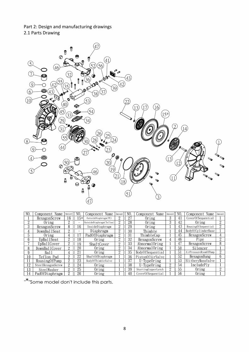
Part 2: Design and manufacturing drawings 2.1 Parts Drawing
9
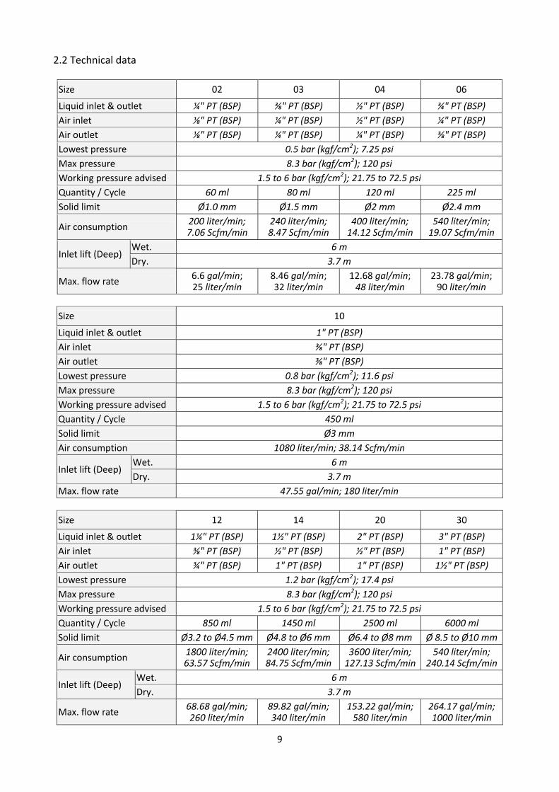
2.2 Technical data
Size 02 03 04 06
Liquid inlet & outlet ¼" PT (BSP) ⅜" PT (BSP) ½" PT (BSP) ¾" PT (BSP)
Air inlet ⅛" PT (BSP) ¼" PT (BSP) ½" PT (BSP) ¼" PT (BSP)
Air outlet ⅛" PT (BSP) ¼" PT (BSP) ¼" PT (BSP) ⅜" PT (BSP)
Lowest pressure 0.5 bar (kgf/cm2); 7.25 psi
Max pressure 8.3 bar (kgf/cm2); 120 psi
Working pressure advised 1.5 to 6 bar (kgf/cm2); 21.75 to 72.5 psi
Quantity / Cycle 60 ml 80 ml 120 ml 225 ml
Solid limit Ø1.0 mm Ø1.5 mm Ø2 mm Ø2.4 mm
Air consumption 200 liter/min; 7.06 Scfm/min
240 liter/min; 8.47 Scfm/min
400 liter/min; 14.12 Scfm/min
540 liter/min; 19.07 Scfm/min
Inlet lift (Deep) Wet. 6 m
Dry. 3.7 m
Max. flow rate 6.6 gal/min; 25 liter/min
8.46 gal/min; 32 liter/min
12.68 gal/min; 48 liter/min
23.78 gal/min; 90 liter/min
Size 10
Liquid inlet & outlet 1" PT (BSP)
Air inlet ⅜" PT (BSP)
Air outlet ⅜" PT (BSP)
Lowest pressure 0.8 bar (kgf/cm2); 11.6 psi
Max pressure 8.3 bar (kgf/cm2); 120 psi
Working pressure advised 1.5 to 6 bar (kgf/cm2); 21.75 to 72.5 psi
Quantity / Cycle 450 ml
Solid limit Ø3 mm
Air consumption 1080 liter/min; 38.14 Scfm/min
Inlet lift (Deep) Wet. 6 m
Dry. 3.7 m
Max. flow rate 47.55 gal/min; 180 liter/min
Size 12 14 20 30
Liquid inlet & outlet 1¼" PT (BSP) 1½" PT (BSP) 2" PT (BSP) 3" PT (BSP)
Air inlet ⅜" PT (BSP) ½" PT (BSP) ½" PT (BSP) 1" PT (BSP)
Air outlet ¾" PT (BSP) 1" PT (BSP) 1" PT (BSP) 1½" PT (BSP)
Lowest pressure 1.2 bar (kgf/cm2); 17.4 psi
Max pressure 8.3 bar (kgf/cm2); 120 psi
Working pressure advised 1.5 to 6 bar (kgf/cm2); 21.75 to 72.5 psi
Quantity / Cycle 850 ml 1450 ml 2500 ml 6000 ml
Solid limit Ø3.2 to Ø4.5 mm Ø4.8 to Ø6 mm Ø6.4 to Ø8 mm Ø 8.5 to Ø10 mm
Air consumption 1800 liter/min; 63.57 Scfm/min
2400 liter/min; 84.75 Scfm/min
3600 liter/min; 127.13 Scfm/min
540 liter/min; 240.14 Scfm/min
Inlet lift (Deep) Wet. 6 m
Dry. 3.7 m
Max. flow rate 68.68 gal/min; 260 liter/min
89.82 gal/min; 340 liter/min
153.22 gal/min; 580 liter/min
264.17 gal/min; 1000 liter/min
10
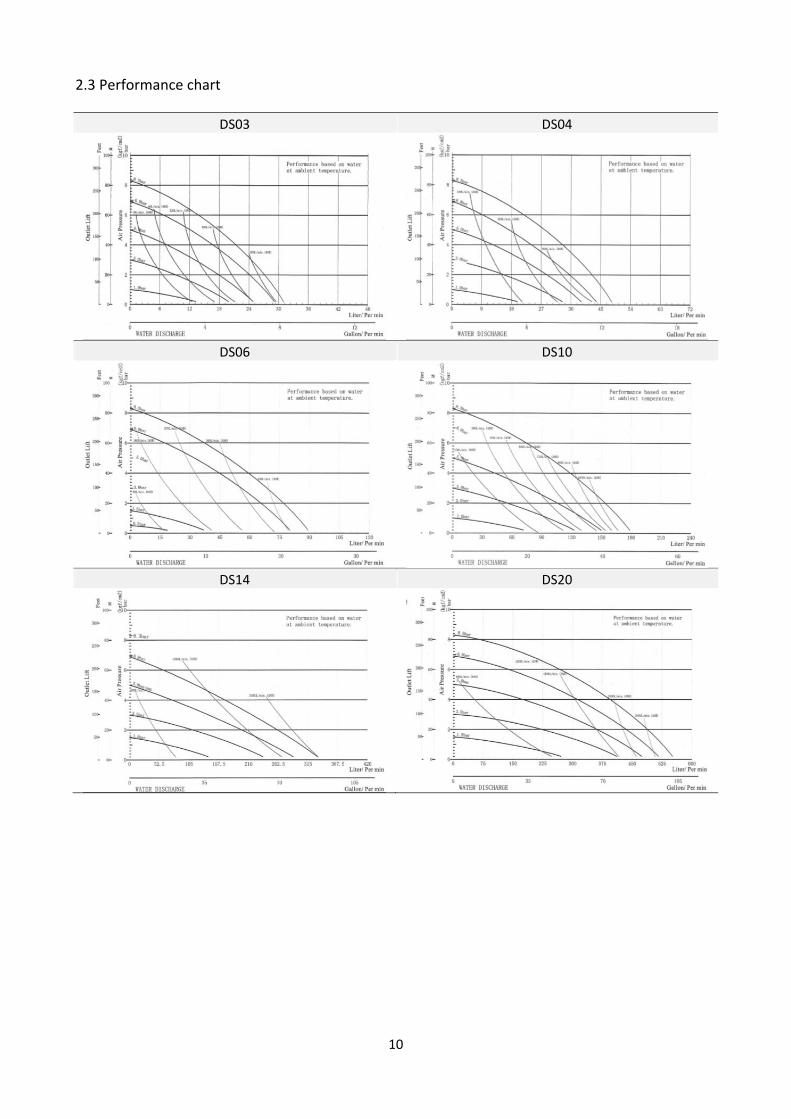
2.3 Performance chart
DS03 DS04
DS06 DS10
DS14 DS20

11
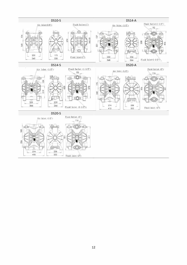
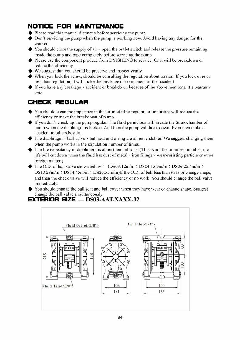
2.4 Dimensions
DS03‐A DS04‐A
DS04‐P DS04‐S
DS06‐A DS06‐S
DS10‐A DS10‐P
12
DS10‐S DS14‐A
DS14‐S DS20‐A
DS20‐S
13
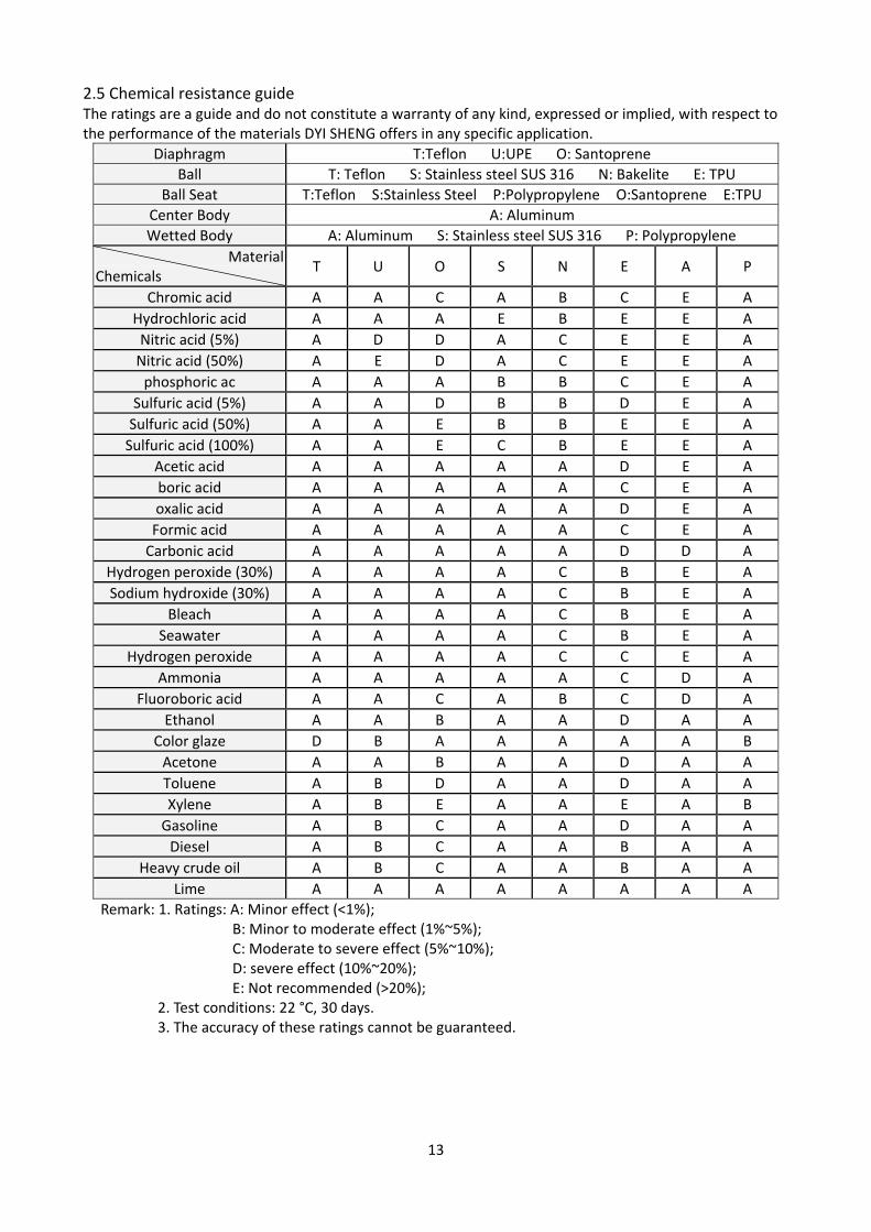
2.5 Chemical resistance guide The ratings are a guide and do not constitute a warranty of any kind, expressed or implied, with respect to the performance of the materials DYI SHENG offers in any specific application.
Diaphragm T:Teflon U:UPE O: Santoprene
Ball T: Teflon S: Stainless steel SUS 316 N: Bakelite E: TPU
Ball Seat T:Teflon S:Stainless Steel P:Polypropylene O:Santoprene E:TPU
Center Body A: Aluminum
Wetted Body A: Aluminum S: Stainless steel SUS 316 P: Polypropylene
Material Chemicals
T U O S N E A P
Chromic acid A A C A B C E A
Hydrochloric acid A A A E B E E A
Nitric acid (5%) A D D A C E E A
Nitric acid (50%) A E D A C E E A
phosphoric ac A A A B B C E A
Sulfuric acid (5%) A A D B B D E A
Sulfuric acid (50%) A A E B B E E A
Sulfuric acid (100%) A A E C B E E A
Acetic acid A A A A A D E A
boric acid A A A A A C E A
oxalic acid A A A A A D E A
Formic acid A A A A A C E A
Carbonic acid A A A A A D D A
Hydrogen peroxide (30%) A A A A C B E A
Sodium hydroxide (30%) A A A A C B E A
Bleach A A A A C B E A
Seawater A A A A C B E A
Hydrogen peroxide A A A A C C E A
Ammonia A A A A A C D A
Fluoroboric acid A A C A B C D A
Ethanol A A B A A D A A
Color glaze D B A A A A A B
Acetone A A B A A D A A
Toluene A B D A A D A A
Xylene A B E A A E A B
Gasoline A B C A A D A A
Diesel A B C A A B A A
Heavy crude oil A B C A A B A A
Lime A A A A A A A A
Remark: 1. Ratings: A: Minor effect (<1%); B: Minor to moderate effect (1%~5%); C: Moderate to severe effect (5%~10%); D: severe effect (10%~20%); E: Not recommended (>20%);
2. Test conditions: 22 °C, 30 days. 3. The accuracy of these ratings cannot be guaranteed.

14
Part 3: Descriptions and explanations necessary for the understanding of drawings
By filling the air chamber (A) the right hand diaphragm is pressed towards the outside. The piston rod thereby pulls the left hand diaphragm to initial position. Valve ball (Bottom left) is pulled out of its position, liquids (blue arrow) flows into the chamber (B). At the same time valve ball (Top left) is fixed in end position by the vacuum. The chamber (B) is thus completely filled with liquids. (see Fig. A.)
After switching of the control valve air flows into the air chamber (B), the air chamber (A) is vented. (see Fig. B.)
liquids (right hand) is drawn in , liquids (left hand) in the chamber (B) is displaced to the outside. Valve ball (Bottom left) presses down, closes and valve ball (Top left) opens the flow path for liquids to the pressure outlet port. that the chamber (A) is already filled with liquids. (see Fig. C.)
By switching of the control valve the air chamber (A) is filled, liquids is drawn into the chamber (B) and the liquids from the chamber (A) is displaced. This sequence is repeated First step. (see Fig. A.)
Part 4: List of applicable Directive and standards
Directive
• EC Directive 94/9/EC Equipment and protective systems intended for use in potentially explosive atmospheres (ATEX)
Standards
• EN 13463‐1: 2009 Non‐electrical equipment for use in potentially explosive atmospheres ‐ Part 1: Basic method and requirements
• EN 13463‐5: 2011 Non‐electrical equipment intended for use in potentially explosive atmospheres ‐ Part 5: Protection by constructional safety "c"
15
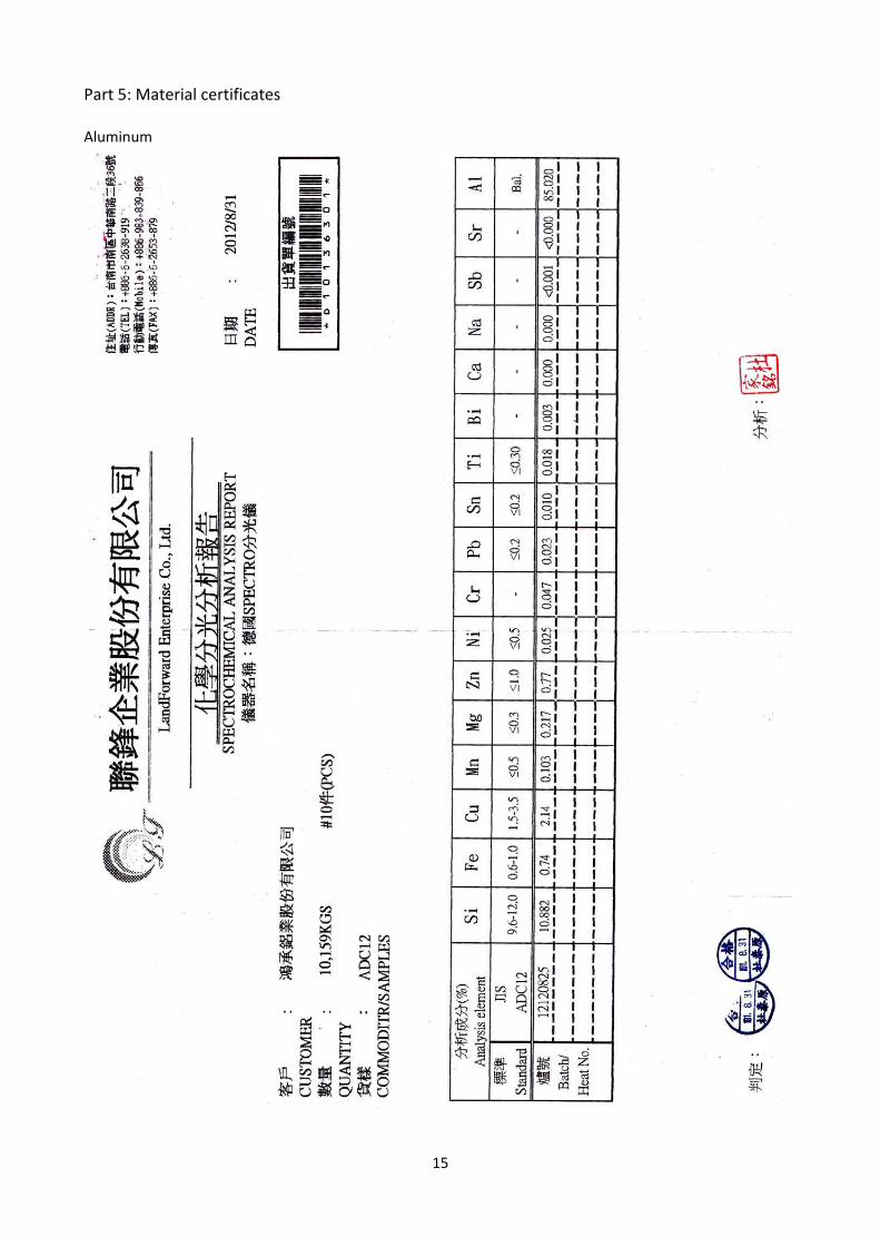
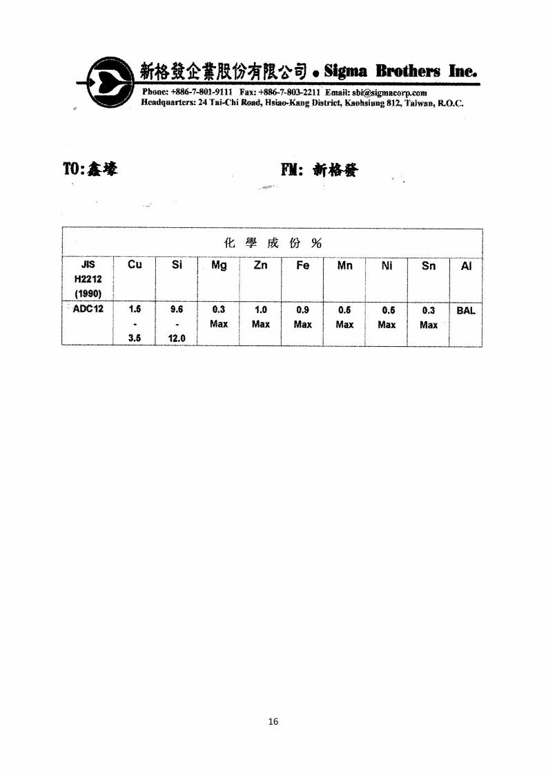
Part 5: Material certificates Aluminum
16

17
Stainless steel

18

19
Polypropylene
20
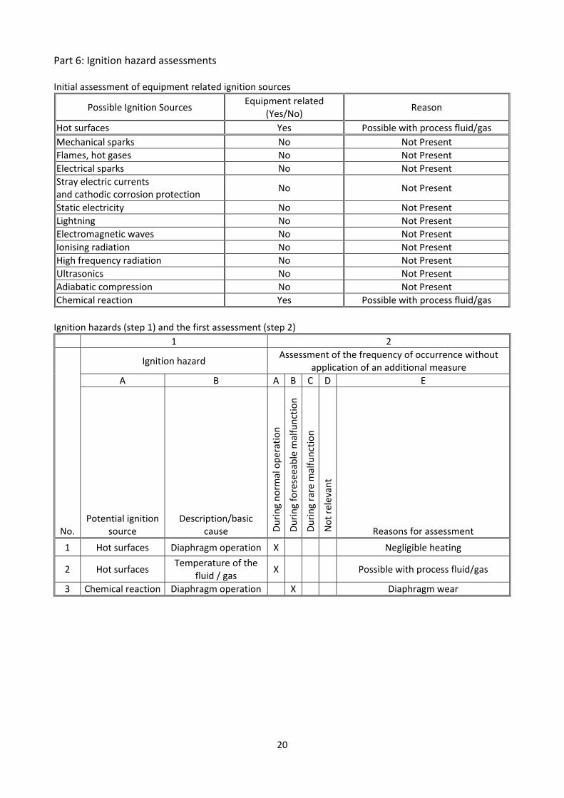
Part 6: Ignition hazard assessments Initial assessment of equipment related ignition sources
Possible Ignition Sources Equipment related
(Yes/No) Reason
Hot surfaces Yes Possible with process fluid/gas
Mechanical sparks No Not Present
Flames, hot gases No Not Present
Electrical sparks No Not Present
Stray electric currents and cathodic corrosion protection
No Not Present
Static electricity No Not Present
Lightning No Not Present
Electromagnetic waves No Not Present
Ionising radiation No Not Present
High frequency radiation No Not Present
Ultrasonics No Not Present
Adiabatic compression No Not Present
Chemical reaction Yes Possible with process fluid/gas
Ignition hazards (step 1) and the first assessment (step 2)
1 2
No.
Ignition hazard Assessment of the frequency of occurrence without
application of an additional measure
A B A B C D E
Potential ignition source
Description/basic cause D
uring norm
al operation
During foreseeable m
alfunction
During rare m
alfunction
Not relevant
Reasons for assessment
1 Hot surfaces Diaphragm operation X Negligible heating
2 Hot surfaces Temperature of the
fluid / gas X Possible with process fluid/gas
3 Chemical reaction Diaphragm operation X Diaphragm wear

21
Protective measures (step 3) and the concluding estimation and categorization (step 4)
3 4
No.
Measures applied to prevent the ignition source becoming effectiveFrequency of occurrence Incl. Measures applied
A B C A B C D E F
Description of the measure ReferencesTechnical
documentation During norm
al operation
During foreseeable
malfunction
During rare m
alfunction
Not relevant
Resulting eq
uipmen
t
category in respect of this
ignition hazard
Necessary restrictions
1
A malfunction is generally agreed as a rare incident under these conditions. The maximum surface temperature is determined under the most adverse conditions.
En 13463‐1: 2009, 8.2 En 13463‐5: 2011, 4.4.1
Specifications of the material
X 3
2
A malfunction is generally agreed as a rare incident under these conditions. Select the matching material.
En 13463‐1: 2009, 8.4 En 13463‐5: 2011, 4.2
Specifications of the material
X 2GD T4/T5
3
A malfunction is generally agreed as a rare incident under these conditions. Diaphragm material is selected according to chemical resistance guide.
En 13463‐5: 2011, 4.4.1
chemical resistance guide
X 2GD T4/T5
Determination of the equipment category
II 2 GD c IIB T4/T5

22
Part 7: test reports 7.1 RoHS test report: Polypropylene
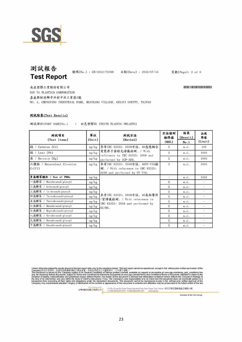
23
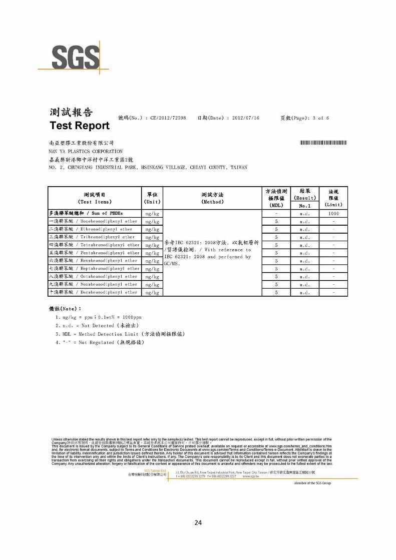
24
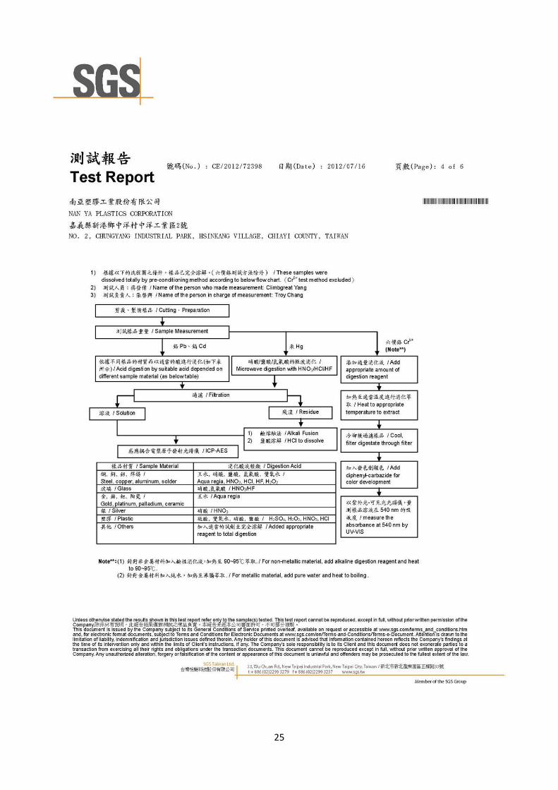
25

26
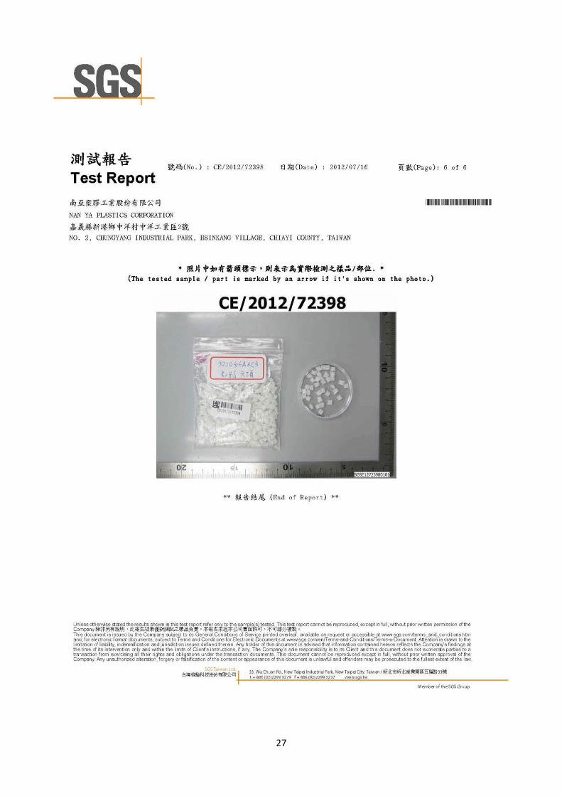
27

28
7.2 Resistance to impact test report:

29
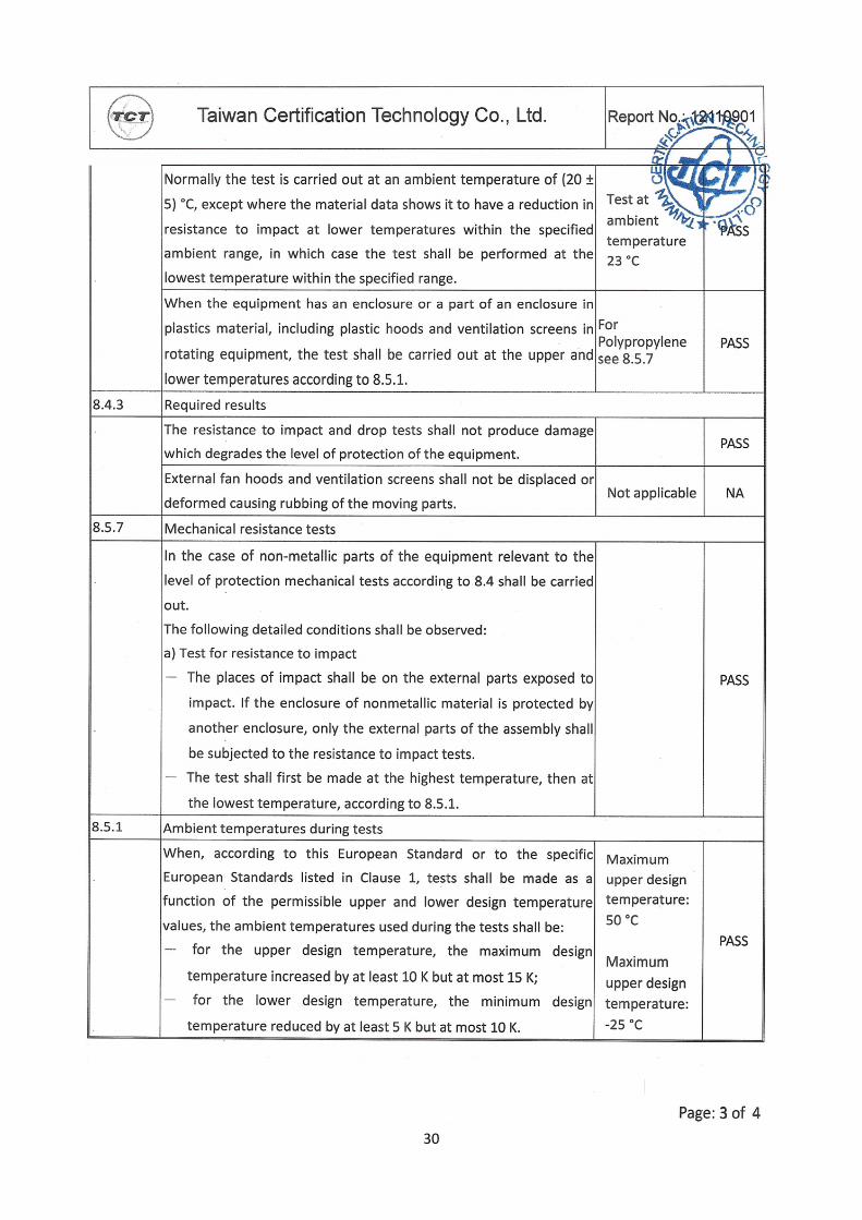
30

31
32
Part 8: Information for use DS03‐AAT‐XAXX‐02

33
34
35
Part 9: Declaration of conformity