technical guide for general-purpose relays
TRANSCRIPT

CSM_GeneralRelay_TG_E_9_1
1
Technical Guide for General-purpose Relays
Overview of General-purpose Relays
What Are Relays?To get an idea of what relays are, think of a children's athletic carnival.
Little A holds on tightly to the baton and passes it to the Big B. This is a relay.
Now lets look at a more technical example.Think of turning on a television with a remote control.
Structure and Principle of Relays
A relay consists of an electromagnet that receives an electric signal and converts it to a mechanical action and a switch that open and closes the electric circuit.
General Relays
Principle of Operation
In this example, we will turn ON a lamp using switch S1 and a relay.
1. Press S1 to turn it ON.2. Current i flows to the operating coil and magnetizes the core.3. The armature is drawn to the core by the electromagnetic force.4. When the armature reaches the core, the moving and fixed
contacts make contact and the lamp lights.5. When S1 is released to turn it OFF, current no longer flows to the
operating coil, the electromagnetic force no longer exists, and the armature returns to its original position by the force of the release spring.
6. When the armature has returned to its original state, the contacts become separated and the lamp turns OFF.
The baton is the signal.
The desire to watch television is converted to a
signal.
Electric energy is applied to the television when it receives the electric signal.
Remote control
Infrared signal received.
A relay receives electric signals and
controls another flow of electricity.
Electric signal
Input Output
Television
Relay Contact
Electric energy
100-VAC power supply
Electric signalTV
A B
Remote control
Electro-magnet
Pressing the remote control power switch creates a signal.
SignalI want to watch TV.
Schematic Diagram Showing the Principle of Relays
Electric signal received and converted into an action.
Switch for controlling the flow of electricity turns ON or OFF.
Input
Attraction
Pressed.
ContactAction transferred.
Coil Armature
Electromagnet Switch
Electromagnetic section
Switch section
Output
Action transferred.
Input
Out
put
Armature
Contact segment
Moving contact
Internal circuit External circuit
Load power supply
Coil power supply
Lamp
Switch i (current)
S1
Fixed contact
Release spring
Yoke Iron core
Operating coil
Attraction

2
Applications for RelaysRelays are used in most machines and devices that use electricity.
TelevisionsStereosMicrowave ovensElectrically heated carpetsAir conditioners
Control panels, e.g., at power stations and transformer Control panels for building management
Machine tools (e.g., molding equipment)Food-industry machinery (e.g., packaging machinery)Industrial robots Industrial machinery and control devices (e.g., programmable controllers)
Medical equipment (e.g., CT scanners)Scientific equipment (e.g., thermostat baths)
Vending machinesAmusement machines
Telephone exchangesTelephonesMeasurement equipment
ComputersFacsimilesCopy machines
AutomobilesRailways
Home electronics appliances
Industrial machinery
Power-related security
Science and medicine
Automatic vending machines and entertainment
Communications and measurement equipment
OA devices
Transportation
Rel
ay A
pplic
atio
ns

3
Types of RelaysThere are different ways to classify relays. The following groupings will be used in this technical guide.
Types of ElectromagnetsRelays are classified into the following types, depending on whether or not they have a permanent magnet.
Non-polarized Relays
Non-polarized relays do not use a permanent magnet in their electromagnetic section.
This means that generally the operating coils do not have polarity. There are some non-polarized relays, such as those with built-in operation indicators or surge-absorbing diodes, whose operating coils have polarity.
Polarized Relays
Polarized relays use the magnetic flux of the permanent magnet in their electromagnetic sections. This means that the operating coil has polarity.
As the name indicates, these relays have contacts and use an electromagnetic operation to mechanically open and close these contacts to transmit and cut signals, current, or voltage.
Classification by Structure Classification by Function
These relays do not have a mechanical moving part that the relays with contacts do. Instead they are made up of internal triacs, resistors, or other semiconductors and electronic parts that transmit and cut the signal or power electronically by the operation of these electronic circuits.
Light
Hingeb
a
Plunger
Coil
Reed switch
Coil
Set coil Reset coilLight
Co
ntr
ol R
elay
s
Relays with Contacts
Relays without Contacts
Hybrid Relays
Note: Relays without contacts are not included in this technical guide.
Hybrid relays are a combination of the best of both relays with contacts and relays without contacts. Semiconductor elements transmit and cut the signal or power and contacts are used to supply the power for the relay.
· Hinged RelaysWith hinged relays, the armature of the electromagnet rotates around a fulcrum. This action directly or indirectly opens and closes a contact.
· Plunger RelaysPlunger relays use mainly the power of a plunger-shaped electromagnet as the armature section to open and close contacts.
· Reed RelaysReed relays consist of a pair of magnetic strips sealed within a glass envelope. These reeds are the contacts. Magnetic flux applied to a coil wrapped around the glass envelope moves these reeds, which opens and closes the contacts.
· Single-side Stable RelaysThe contact turns ON or OFF only while an input signal is received. Single-side stable relays have no other special functions in their operation elements.
· Latching Relays (Bistable Relays) The contact turns ON or OFF when an input signal is received and maintains that status even if the input signal is cut.
· Other Relays· Ratchet Relays· Latch-in Relays· Time Relays· Motor Relays· Thermal Relays
No polarity
Polarity
Polarity
+
−
No polarity
Working gap
Core
Core
Armature
Rotating axis
Coil
Coil
−
−
Yoke
+
+
Movable block
Armature Permanent magnet
Permanent magnet
N
S
N
S
Moving Loop System (OMRON name)
Super Moving Loop System (OMRON name)

4
Description of Relay Operation
Single-side Stable Relays
Release State• Battery Not Connected to the Coil
No current is applied to the operating coil, so the electromagnet does not operate. The armature is pulled by the force of the release spring in the counterclockwise direction and, as a result, the moving contact makes contact with the normally closed contact (turns ON) and the normally open contact stays disconnected from the moving contact (remains OFF).
Operating State• Battery Connected to the Coil
When current flows to the operating coil the electromagnet is magnetized and the armature is drawn to the core. As a result, the moving contact moves away from (turns OFF) the normally closed (NC) contact and connects (turns ON) the normally open (NO) contact.
Latching Relays (also called 'Bistable' or 'Keep' Relays)Magnetic Latching Relays: Two-coil Latching Relays
Relaxed State (after Reset)• Battery Not Connected to Coil
The diagram shows the relay in the relaxed state.
Latching relays are the same as the single-side stable relays described previously except that the core, yoke, and armature are made from semi-hard magnetic material and there are at least two coils in the relay.
Operating State (Set)
When current flows through coil A, the electromagnet (made of semi-hard material) is magnetized and the armature is attracted to the core.
As a result, the moving contact moves away from the normally closed (NC) contact (turns OFF) and makes contact (turns ON) with the normally open (NO) contact.
In the set state, the residual magnetic flux in the semi-hard magnetic material (material that has properties similar to a permanent magnet) will keep the armature attracted to the core even if a current is no longer applied to coil A.
Release State (Reset) →Relaxed State
If a current is applied to coil B, which is wound in the opposite direction to coil A, the residual magnetic flux in the semi-hard magnetic material will reduce and the magnetic attraction will weaken. The power of the release spring will become stronger than the magnetic attraction, so the armature will release and the relay will be in a relaxed state.
When the armature has released, there will be almost no residual magnetic flux in the semi-hard magnetic material.
Note: In contrast to the hard magnetic material used in a permanent magnet, semi-hard magnetic material requires less energy to magnetize and de-magnetize.
Moving contact
+
+
−
−
Normally closed
contact (NC)
Normally open contact (NO)Release
spring Coil
Armature
Core
Press
+
+
−
−
Cur
rent
Core
Coil A (set)+
−+
−
(b)
Coil B (reset)
Yoke
Armature
(a)
Releasespring
Coil A (set)+
−+
−
(b)
(a)
Coil B (reset)
Coil A (set)+
−+
−
(b)
(a)
Coil B (reset)
Coil A (set)+
−+
−
(b)
Coil B (reset)
(a)

5
Using General-purpose Relays
Relay Construction and PrinciplesNon-polarized Relays
There are various magnetic circuits using non-polarized relays, but this section will describe the most common type, the hinged relay.
The force to switch the relay switch is obtained from an electromagnet. Electromagnets generate the following forces.
.....................1
Here,
........................2
If we insert equation 2 into equation 1:
......3
When the magnetic resistance Re between the core and the armature is large, the following approximation applies:
..................4
g: Gap between the core and the armature (armature gap)
......5
There are various structures for electromagnets in non-polarized relays. The following diagram shows some typical structures.
Example Structures of Electromagnets in Hinged Relays
Example Structures of Electromagnets in Plunger Relays
As an approximation, magnetic flux φ is proportional to the current of the operating coil. The resistance of the operating coil, on the other hand, fluctuates with the temperature of the coil (approx. 0.4%/°C).Accordingly, the voltage at which the relay operates is affected by the temperature of the operating coil. The must-operate voltage increases at high temperatures and decreases at lower temperatures. OMRON uses 23°C as the standard temperature for operating coils.
V
I
NR
S
F
φ
Yoke
Core
R: Coil resistanceN: No. of coil windingsI: Coil currentV: Coil voltageThe following relationship exists between I, V, and R: I = V/RF: Attractive forceφ: Magnetic fluxRe: Magnetic resistance of
magnetic circuit loopS: Attractive surface area
φ 2 F = 2µ0S
φ = ReNI
[ ]1F = 2µ0S Re
NI 2•
gµ0S
Re =
[ ]µ0SF = 2 g
NI 2•
Examples: MY, MK, etc. Examples: MM, G2R, etc.
Example: LZN Example: G2A
Plunger

6
Polarized Relays
Polarized relays use permanent magnets, which increase the attractive force by the magnetic interplay between the permanent magnet and the coil.
Magnetic circuits with permanent magnets create the magnetic attraction by the interplay between the magnetism of the coil and the magnetic flux of the permanent magnet.
The symbols have the following meanings:
Pc: Permeance viewed from the coilPcm: Mutual permeance between the coil and the permanent
magnetPm: Internal permeance of the permanent magnetφ0: Magnetic flux of the permanent magnetP0: Total permeance
The attractive force of polarized relays displays the graph shown in the following diagram.
Polarized relays basically have an attraction curve suitable for latching relays. To create a single-side stable relay, the attraction curve needs to be changed or a bias needs to be applied to the load curve.
The following diagram shows the structures of polarized relays.
V
I
N
NF
S χ
2 21 1
Attractive force of the coil alone
Attractive force between the coil and the permanent magnet
Attractive force of the permanent magnet alone
2F = + (NI)(NI) +• •δx δxδxPmδPc δPoδPcmφ0 [ ]Pm
φ0
Stroke S
Attr
activ
e fo
rce
Attr
activ
e fo
rce
F
S
F
S
F
S
F
Unbalanced Attractive Force
Bias Applied to the Load
Bias
SN SN
N
S
N
S
N
S
N
S
Example: J7A
Examples: G5A, G6A, G6B, G6C, G6E
Examples: G6H, G6N, G5H

7
Quality and Reliability
Basic Quality and Reliability Information
(1) Quality and Reliability• Quality and Reliability Mean SatisfactionWe use a variety of tools in everyday life (including intangible tools such as services and information and tangible tools such as relays and electrical appliances) to make our lives richer.
If,
...it would no doubt make us quite irritated. But if,
...we would no doubt feel very satisfied.
The concepts of quality and reliability are easily understood if they are considered as scales of satisfaction.
Let's think of quality and reliability in the following way:
Quality: .....Degree of satisfaction at the time of purchase.Reliability: ..Degree of satisfaction while using the product.
Extent to which you want to use the product again.
If we think in these terms, then the earlier example could be expressed as follows:
Inexpensive ...................................................................QualityAvailable when you want it ...........................................QualityColor, shape, functions, features ...................................QualityCan be used with confidence ........................................Quality
Always inexpensive....................................................... ReliabilityAlways available when you want it ............................... ReliabilityContinues to have consistent color, shape, functions, and features...................................................................................... ReliabilityCan be used with confidence for the desired period..... Reliability
Classified in this way, quality and reliability are very similar, but reliability, as you can see, has a time element (always, continuously, for the desired period).
a very expensive item......wasn't available
when we wanted it......and the color, shape, functions, or other features were inconsistent...
...and it broke right away or caused injury...
...the item was inexpensive......and available to buy when we wanted it...
...and had consistent color, shape, function, and other features...
...and we could use it with confidence for as long as
we needed to...

8
• The Scope of Quality and Reliability
Let's look at the previous example again.
It may be readily understood that concepts such as a relay's color, shape, functions, and other features are part of the quality, but perhaps it is more difficult to concede that price and availability are also components of the quality.
Let's go back to the beginning again.
We human beings repeat the process of inventing and modifying in our daily lives. In that process a variety of desires surface and we express them as requirements.
It is the commercial sector that takes these requirements, organizes them, and turns them into products. It can be said that the ability of a product to satisfy the requirements of a wide range of personalities is an indication of its quality. In broad terms, a product and everything related to it can be considered to come under the term 'quality.'
The same can be said of reliability.
If you think of it this way, the scope of quality and reliability includes all of the following:
(2) What Are Quality and Reliability?• Quality
Let us look at this in a more specialized way.
Quality is “The totality of features and characteristics of a product or service that bear on its ability to satisfy stated or implied needs. Needs can be defined in terms of usability, safety, availability, reliability, maintainability, overall cost, environmental impact, or other desired characteristics.”
(As defined by the ISO in ISO 8402: 1986, 3.1)
The term “relative quality” is applied to the ranking we use on a daily basis to say that a product from one company has better quality than a product from another company. This term “relative quality” is distinct from “quality.”
When making detailed, quantitative technical assessments the terms “quality standards” and “quality scales” are used.
As you can see, this term “quality” is a very broad concept and under ISO standards reliability is included in it.
• Reliability
Reliability is: “The ability of an item to perform a required function under stated conditions for a stated period of time.”
(As defined by the ISO in ISO 8402: 1986, 3.18)
People, plants, and animals live in a variety of environments. We sometimes get sick and receive treatment; health checks and a variety of precise tests help in the early detection of disease, while vaccinations prevent and reduce illness. We do exercises and join fitness clubs to maintain our health to live enjoyable lives.
These things that we do can be classified into two groups:
1. Things that help prevent illness.2. Things that help us recover quickly when we are sick.
If we apply the concept of “reliability” to this, we can express it as follows:
1. Does it increase resistance to illness or injury? ...... Reliability2. Does it help recovery when we get sick or injury?
Does it prevent illness or injury?..............Ease of maintenance
A more scholarly definition of these might be as follows:
1. ReliabilityThe probability that a system or product will fulfill its required functions without failure for the prescribed period under the given conditions.
2. MaintainabilityThe probability that the maintenance of a repairable system or product can be completed within a specified time frame when that maintenance is performed under specified conditions.
3. AvailabilityThe probability that a repairable system or product will maintain its function at a specific point in time.
Reliability includes the three elements of the degree of reliability, maintainability, and availability. For systems and products that cannot be repaired, only the degree of reliability is considered. For those that can be repaired, the degree of reliability, maintainability, and availability are important.
Relays are not repaired and reused, so the degree of reliability is the important element.
• Quality and Reliability of Products (Both Tangible and Intangible)
• Quality and Reliability of Service • Corporate Quality and Reliability
Color and shape Catalog Corporate philosophy
Operation (functions) and other capabilities (characteristics) Instruction Manuals Policies
Safety Specifications Organization and structure
Price Product presentations Systems
Availability Technical services Personnel

9
• Operational ReliabilityThe degree of reliability of a device during operation is called operational reliability (Ro).
Operational reliability can be easily understood from the following formula.
RO ≅ RI•RU
In this formula, RI is the “inherent reliability,” the value measured and guaranteed by the manufacturer under a standard environment. RU is the “use reliability,” the value determined after the system or product has been in various environments, in the process through to receipt by the end user and actual use of the system or product. Operational reliability (Ro) is approximated as the mathematical product of inherent reliability (RI) and use reliability (RU) so both RI and RU need to be improved to improve Ro.
To improve inherent reliability, manufacturers need to consider in the design phase the conditions under which the system or product is used and make the design appropriate to those conditions. The production system also needs to be improved to support the reliability of the design. On the other hand, end users need to consider the type of load and the operational environment when using a system or product to improve the use reliability.
The following diagram shows this relationship.
The minimum applicable load (reference value) listed in catalogs and other material is the inherent reliability in standard circumstances expressed by the failure rate λ60 = 0.1 × 10⁻⁶ (P level).
In this equation “λ60” means that the failure rate is 60% of the reliability level.
(3) Quality and Reliability Terminology• Reliability ScalesThe following table shows scales often used for reliability.
Reliability Scales
Operational Reliability
RO
Inherent Reliability
RI
Design ReliabilityDesign based on issues such as application, method of use, environment where system or product is used, manufacturing method, and theory.
Manufacturing ReliabilityManufacturing that uses good quality material, uses processes based on the design, and is performed in a clean working environment.
Use Reliability
RU
Selection Based on Specifications, Performance, and UsabilitySelecting a relay based on load type, operating environment, and other usage considerations.
Method of UseA Relay is used while being aware of issues such as the ease of maintenance and inspection, deterioration, and monitoring of system or product life.
Reliability scale Definition according to JIS (Z8115) Example product application
Reliability (R) The probability that a system, equipment, or part will fulfill its prescribed functions for the intended period under the given conditions.
Aerospace systems
Failure rate (λ) The rate at which a system, device, or part which has been operated up to a particular point in time will fail within a specific unit of time.
Electronic componentsMechanical components
Mean Time Between Failures (MTBF)
The mean operating time in which a system, equipment, or part operates normally between two incidences of repair.
ComputersRolling stock
Mean Time To Failure (MTTF)
The mean operating time until a system, equipment, or part that is not repaired fails. Electronic components
Useful Life The period for which the failure rate is less than a specified value. Household appliancesEquipment and devices
Maintainability The probability that the maintenance of a repairable system or product can be completed within a specified time frame when that maintenance is performed under specified conditions.
Rolling stockProduction equipment
Mean Time To Repair (MTTR) or Mean Down Time (MDT)
The mean time during which the system or product is non-operational. (MTTR and MDT are used interchangeably. MTTR is used, however, when talking about corrective maintenance.)
Electronic exchangers
Availability Availability is the probability that a repairable system, equipment, or part will maintain its function at a specific point in time. This probability is often found using the following equation:
Production equipmentComputers
(Possible operating time)
(Possible operating time) + (MTTR)Availability =

10
• Basic Terminology
The following basic terminology is used in relation to reliability.
1. Failure Probability Density Function.............. f(t)
(The ratio of the number of failed units in time t against the total number of units.)
2. Cumulative Failure Distribution Function....... F(t)
(The ratio of the number of failed units from time 0 to time t against the total number of units.)
3. Reliability Function........................................ R(t)
= 1−F(t)
(The ratio of the remaining number of units at time t against the total number of units.)
4. Instantaneous Failure Rate ...............................λ (t)
(The ratio of the number of failed units in time t against the remaining number of units.)
• Operating Characteristic Curve (OC Curve)
The following points need to be understood before evaluating the reliability of each relay lot.
If all relays in the lot were inspected, the failure rate λ would be the broken line ABCDE in the following diagram, because an estimated range does not need to be considered.
However, if all items in the lot were inspected to check the degree of reliability, there would be no relays left to mount into devices. That is why only a few samples are taken from a lot and used to estimate the degree of reliability of the whole lot. The curve ACE indicates the success or failure of a lot.
The criterion - failure rate λ1 (point C) - is 60% from the consumers' perspective, which indicates that the reliability level is 60%. The vertical line in the region encompassed by points A, B, and C indicates if there is a risk of failure even if the failure rate is smaller than λ1 and is called the “producer's risk.” The line in the region encompassed by points C, D, and E indicates the risk of passing inspection even if the failure rate is greater than λ1 and is called the “consumer's risk.”
The meaning of λ60 and the other factors needs to be understood in order to completely grasp the concept of reliability. These are the factors used to evaluate reliability because whole lots cannot be tested.
Many of the reliability tests have very low failure rates and many of them are breakdown tests. On the other hand, because the tests require a lot of time, a reliability level of 60% is deduced from the levels of significance α and β and the cost balance. This reliability level is listed for reference in relay catalogs. Relays are a component in important systems and if the failure rate is to be guaranteed, the reliability level needs to be raised by changing the sampling conditions and the acceptance criteria.
When relays are shipped, an initial check and tests that do not cause damage or wear can be performed, e.g., the must-operate voltage, must-release voltage, contact resistance, dielectric strength, can be checked before shipment for all relays in a lot. When such tests have been performed, the relays will either pass or fail the tests and α and β values in the graph will be close to zero.
Refer to JIS Z9001 General Rules for Sampling Inspection Procedures for information on sampling tests. Refer to JIS C5003 General Rules for Determining the Failure Rate of Electronic Components During Tests for information on relay failure rate tests.
• Operating Characteristics Curve for Evaluating Test Results
0
f(t0)dt
t0+dtt0t
f(t)
f(t)
∞
Meaning of f(t)
f t( ) td0
∞∫ 1=
F(t)
0
1
F(t0)
t0t
Meaning of F(t)
F t( ) f t( ) td0
t
∫=
R(t)
0
1
R(t0)
t0t
Meaning of R(t)
R t( ) f t( ) td0
∞∫=
λ (t)
0
λ (t0)
t0t
Meaning of λ(t)
f(t)R(t)λ(t) =
d LnR(t)dt
= −
Producer's risk: αA B
C
DEλ2 λ1 λ30
1
60%
0.4Consumer's risk: β
Failure rate λ (/operation)
Lot a
ccep
tanc
e ra
te L
(λ)

11
• Bathtub Curve
It is widely known that the mortality rate of human beings follows the curve in the following diagram. Other animals, such as fish, also show the same trend. Devices have a failure rate rather than a mortality rate, but devices still follow this same curve, called a “bathtub curve.” The life of relays, too, follows exactly the same curve as shown in the diagram. A better understanding can be gained if the life of a relay is considered in three separate periods.
Bathtub Curve
1: Early failure period(0<t<t1)
2: Random failure period(t1<t<t2)
3: Wear-out failure period(t<t2)
In the above diagram, 1 is the early failure period.
During this period, the failure rate decreases as the number of operations increases. Although it may appear that items that were no good have improved during this period, it actually means that items with elements that may result in malfunctions have been weeded out early and only sound items remain. This stage needs to be completed before a product passes to the end user. This stage is also called the debugging stage.
With relays, the manufacturer tests the basic characteristics of all relays in a lot before shipment, e.g., by testing must-operate and release voltage, contact resistance, dielectric strength, time characteristics, and coil impulse. These tests are performed to bring the early failure rate close to zero.
2 in the above diagram is the random failure period.
The main feature of this period is that the failure rate does not change much no matter how many operations there are. It is during this period that a product performs its functions effectively. It is desirable for both manufacturer and end user that the failure rate during this period is at zero, but this is currently not possible. All that can be done is to strive for as close to zero as possible. It is important to understand that failure rates vary for each model depending on a variety of factors and that the selection of model and operating conditions have a large impact on the failure rate of a device.
3 in the above diagram is the wear-out failure period.
This period is characterized by an increase in the failure rate with the increase in the number of operations and the ultimate deterioration and breakdown of all items. Mechanical components with parts that operate mechanically, such as relays, always deteriorate, deform, and fatigue, and they need to be considered in terms of having a limited service life.
In general, relay failure and the life of relays can be considered in the following ways.
1. FailuresFailures include changes in function that can be detected by monitoring, random malfunctions, and intermittent deterioration in characteristics.
2. LifeThe service life of a relay ends when it no longer functions due to accumulated deterioration, deformation, or fatigue.
• Weibull Distribution
The bathtub curve, described previously, can be expressed using the Weibull distribution function.
The Weibull distribution gets its name from the Swedish engineer, W. Weibull, who first applied this distribution to the life of steel balls. The Weibull distribution provides a good explanation of how destruction of the weakest point in one part leads to the breakdown in overall function. The concept is an expansion of exponential distribution. One of the main practical features is that Weibull plotting paper can be used for easy data analysis. If m < 1, it is the early failure period. If m = 1, it is the random failure period. If m > 1, it is the wear-out failure period. The Weibull distribution can be expressed using the following function and graph.
1. Weibull Distribution Function
F(t) based on differences in m
2. Failure Probability Density Function
f(t) based on differences in m
λ (t)
0t
t1 t2
21 3
[ ]t0(t − γ) m
F(t) = 1 − exp −
F (t)
0
1
1
m < 1
m > 1
m = 1 F(t) = 1 − exp [−tm]
t
e − 1e
[ ]m (t − γ) m − 1
t0 t0(t − γ) m
f (t) = exp
f(t)
0
1
m < 1
m > 1
m = 1f(t) = mtm−1exp [−tm]
t

12
3. Instantaneous Failure Rate
λ (t) based on difference in m
In this graph m: Shape parameter
to: Scale parameter
γ: Position parameter
A comparison of the above diagram and the bathtub curve will reveal that m < 1 corresponds to 1, m = 1 corresponds to 2 and m > 1 corresponds to 3.
The Weibull plotting paper is created based on this Weibull distribution function. Failures can be analyzed using the Weibull plotting paper.
The vertical axis on the Weibull plotting paper is F (t) and the horizontal axis is t. Test results are plotted on this paper and analyzed. Relays can be said to have better characteristics if the slope of the straight line drawn from the plotted results for those relays is large and the line is toward the right side of the graph. This means that as a group, the relays will reach the end of their service life and that it will be a long service life.
These characteristics are constantly pursued during relay design and production. There are many factors that cause failure and manufacturers are constantly striving to produce relays that will reach the end of their service life together.
For the relay consumer, on the other hand, it is easier to determine device maintenance schedules and predict the end of service life if the life expectancy is clear. Refer to Using Weibull's Plotting Paper issued by the Japanese Standards Association and other specialist publications for details on analysis methods.
• Exponential Distribution
Exponential distribution can be used to model the number of operations without failure during the random failure period. Exponential distributions are a type of gamma and Weibull distributions and are the most basic distributions used to model reliability life. Gamma distributions are used to model how many random shocks are required (k times) before a failure occurs. If k = 1, i.e., failure occurs after one shock, gamma distribution is equal to exponential distribution.
As the earlier diagram shows, it is an exponential distribution if the shape parameter m = 1 in a Weibull distribution.
The functions for the exponential distribution are as follows:
1. Reliability functionR(t) = exp [−λ t]
2. Failure probability density function
3. Instantaneous failure rate
Relationship Between Exponential Distribution and Other Distributions
• Normal Distribution
During the wear-out failure period, failures do not occur only once during a certain period. The distribution shown on: page 11 models the occurrence of failures.
Weibull distribution can be used to model m > 1. Normal distribution can also be used, however, if there is variation.
Normal distribution uses the following functions:
1. Reliability function
2. Failure probability density function
3. Instantaneous failure rate
Service life can be indicated by a percentage of remaining units or as an average. With relays, 95% units remaining is used to indicate service life, but average service life may be used depending on the manufacturer and model.
f(t)1 − F(t) t0
mλ(t) = = (t − γ) m−1
0
1
m < 1
m > 1
m = 1
λ (t) = mt
t
λ (t)
m − 1
d [1 − R(t)]dt
f(t) = = λ exp (−λ t)
f(t)R(t)
λ(t) = = λ (constant)
f(t) = λk = 1
m = 1f(t) =
f(t) = λe−λt
mtm−1
(λt)k−1e−λt
e
(k − 1) !
t0
Gamma Distribution
Exponential DistributionWeibull Distribution
1/t0 = λ
tmt0−
R t( ) 1
σ 2π--------------- e
t µ1–( )2
2σ2--------------------– td
t∞∫=
1f(t) =σ 2π
e − (t − µ0)2σ2
f(t)R(t)
λ =

13
OMRON Initiatives for Product Quality and ReliabilityAs mentioned earlier, product quality is the degree of satisfaction felt in relation to a requirement. From this perspective, how a product or service is created and the systems and management methods for creating those products and services become important.
This section shows part of the procedure used to create OMRON relays.
(1) Development
The following is an outline of the procedure for developing relays.
(2) The OMRON Perspective on Quality and Reliability
In the past, many Japanese companies have spoken about the importance of quality. The pursuit of quality has focused mainly on the production floor, with thorough monitoring, improved monitoring standards, and improved work practices starting from the production floor.
This concept of quality was focused mainly on the product. In recent years, however, the importance of services, corporate philosophy, and the systems in place to implement these has been recognized. The concept of quality has broadened to include the idea that product quality will necessarily improve if these other factors are implemented.
In its production of relays, OMRON has reorganized its product service and all systems relating to it and has received ISO 9001 and ISO 9002 certification (JQA, BSI).
Product planning
Design
Trial mass production
Mass production
Design review
Review
Review
Review
Determining Planned QualityIn this stage, the market requirements are researched and draft proposals and decisions are made on what products with what specifications will be provided for what applications.Quality during this stage will always be around 100%.
Evaluating Appropriateness of Planned Quality
During this stage, evaluations are made to determine that the planned quality meets market needs and that nothing is being left out.
Determining Designed QualityDuring the design stage, each planned quality item is addressed to determine what technology will be used to achieve the planned quality items, what kind of relay construction is required, and what kind of design targets and backup is required for each element of that construction. The appropriateness of the design targets and any issues relating to planned quality are evaluated by creating prototypes.
Evaluating Appropriateness of Designed Quality
This stage is used to evaluate if the designed quality is appropriate for the planned quality and whether or not there were any unusual signs in the prototype.
Determining Production QualityThis stage is used to evaluate the development of the production system used to achieve the design quality (equipment, personnel, standards, storage systems, etc.) and the appropriateness of this system.
Evaluating the Appropriateness of Production Quality
This stage is used to evaluate the appropriateness of the production quality in relation to the planned quality and designed quality and to evaluate if there were any unusual signs in the prototype.
Creation of Production QualityIn the initial mass production period, initial instability control and other measures are taken to promote optimization of every process from purchase of raw materials through to delivery of the final product.
Design ReviewsDesign reviews are undertaken periodically or on an ad hoc basis to ensure that designs are up to date with changes in the market and consumer needs.If necessary, these reviews encompass all stages from planning through mass production. It includes a review of market defects and developments in technology.

14
Relay Failures
(1)Relay FailuresThe main function of relays is to open and close or switch outputs (contacts) under certain input conditions. A failure is any condition that deviates from this.
Relay failures can be broadly classified as follows, based on the relay elements:
The most frequent failures are:
The following section looks at failures by relay type.
• Signal Relays
1. Faulty Contacts
In some dry circuits, increased contact resistance (of several hundred milliohms) becomes a problem. In such cases, organic matter that attaches to the surface of contacts affects contact resistance, so OMRON bakes (heats under high pressure) the contacts to remove the gases that are emitted by the molded components of relays.
OMRON is also developing and gradually incorporating into our relays molded components with greatly reduced gas emissions.
2. Coil Disconnections
There is a strong requirement for signal relays to be small and very sensitive. For this reason, the coil conductors are getting thinner and thinner. Signal relays are mounted to PCBs and cleaned, but the ultrasound energy gets concentrated on the coil conductor and sometimes causes disconnection. In particular, if a washer using a single transmitter with a frequency of several tens of kHz or water is used as the cleanser, it is very possible that strong stationary waves will be generated and cause disconnection of coil conductors. This needs to be checked beforehand.
• General Relays and Power Relays
1. Faulty Contacts
The main application for general relays and power relays is load switching in areas where arc discharges occur. Under these conditions, nitric acid reactions cause corrosion, so many relays are enclosed in cases or exposed. These relays are easily affected by ambient factors, such as dust and gas.
In control panels, it is important to ensure that wire scraps, filings left over from panel work, paint, or other material does not go inside relays.
2. Humming
In general, electromagnets in AC relays use shading coils. The principle behind these coils is that the flux that passes through the magnetic poles of the shaded and non-shaded sections creates mutual attraction and appears to provide an even attractive force.
The apparent even attractive force has a narrow range. For example, a foreign body on the magnetic pole may cause wear of the magnetic pole with repeated relay operation.
It is technically impossible with this type of coil to completely resolve this problem.
Humming does become a problem in some relays built into appliances and devices in domestic homes and residential areas. In such cases, either DC relays or a combination of diodes to provide full wave rectification and DC relays need to be used.
3. Welding
Generally AC relays use the same power supply for operation and the load. This can be the cause of failure.
With large lamps, power transformers for various devices, motors, and similar devices there may be an inrush current many times or many tens of times the rated current when the power is turned ON. This causes the must-operate voltage applied to the relay coil to drop suddenly, which causes chattering. This chattering makes the contacts repeatedly open and close in a short period, which may result in the welding of the contacts.
This may make users hesitant to use these relays, but all components, equipment, and devices can break down.
Failures are a deviation from the required functions, so understanding relay failure modes and ensuring failsafe, foolproof designs of equipment and devices is fundamental to providing satisfaction to the end user.
Input-side failures Not specified current No current Disconnection
Overcurrent Short-circuit
Failures between input and output sides
Does not perform specified operation
Faulty operation release Stuck or variations in characteristics due to impurities
Faulty insulation Insufficient insulation between input and output sides
Deterioration of insulation
Output-side failures Specified conduction not obtained Contact does not close Faulty contact
Not specified insulation Contact does not open Sticking (welding, gluing, or locking)
Deterioration of insulation
1. Faulty contacts2. Coil disconnection3. Humming of AC relays

15
• Incorrect Current
Coil disconnection (no current flowing at all or intermittent current flow) is the main cause of failures where the coil current does not reach the specified value even though the rated voltage is being applied. Another possible cause in AC relays with built in diodes for full wave rectification may have part of the diode stuck open.
The most common causes of coil disconnection are as follows:
1. Resonance from ultrasonic cleaning of PCBs2. Resonance from the control panel3. Corrosion of the coil conductor due to nitric acid reactions4. Electric corrosion
The following can also be mistaken for failures: Reduced current resulting from increased coil temperature of DC relays (approx. 0.4% reduction per 1°C for a standard temperature of 23°C) and incorrect polarity of relays with built-in diodes to block reverse current.
• Overcurrents
The following possible causes exist for overcurrents when the rated voltage is applied.
1. Inter-turn short-circuits between coil conductors2. Shorts in internal elements, e.g., of surge-absorbing diodes3. Malfunctions in AC relays• Incorrect polarity of relays with polarity (e.g., relays with built-in
surge-absorbing diodes) can be mistaken for a failure.
• Specified Operation Not Performed
Specified operation differs slightly for each relay model, so generalizations are difficult. One obvious example of failure to perform correct operation is when ants, cockroaches, or other insects get inside the relay and prevent operation all together.
• Specified Power Not Obtained
Generally these are called faulty contacts and can be classified as follows:
1. Faulty contacts caused by contact follow resulting from contact wear and from loss of contact pressure (end of service life).
2. Faulty contacts caused by a foreign body (e.g., dust, molding powder, wire scraps, insulation coating, or carbon) between the contacts.
3. Secondary faulty contacts caused by input side failures, failures between input and output sides, and welding of switching contacts on output side affecting other poles.
A faulty contact may have no power at all or may have power that exceeds the maximum value for the circuit used, as a result of accumulated carbon or other matter on the surface of the contact.
• Faulty Insulation
The following faulty insulation failures occur between inputs and outputs.
1. Flashovers caused by the arc discharge between contacts during load switching being bent by an external magnetic field or the magnetic field generated by the operating coil and reaching the coil terminal.
2. Reduced insulation resistance or dielectric strength as a result of carbon generated during arch discharge between contacts during load switching or accumulated dust on contacts.
3. Flashovers caused by surge voltage from direct or inductive lightning.
• Specified Insulation Not Obtained
This type of failure can be classified into the following groups:
1. Deterioration in insulation due to the carbon generated by arc discharge between contacts during load switching and dispersal and accumulation of powder from contact wear.
2. Faulty insulation due to wire scraps and other foreign matter.3. Contacts not opening because of welding, gluing, locking, or
other sticking problems.4. Secondary contact opening failures caused by factors such as
input-side failures and failures between inputs and outputs.5. Deterioration in insulation due to migration, whiskers, trees, and
other chemical and physical phenomena.
Correct
S
+
−
Incorrect
S
+
−
X X
Sho
rt-c
ircui
t

16
Problems Occurring during Relay Use Relays undergo changes during use and storage. These changes can be considered to be deterioration rather than failures. This section describes the deterioration problems. Information about these problems is useful for preventing failures during use and for planning maintenance. Some unusual problems occur not due to the relay alone but are the result of particular or harsh use. This section also discusses these problems, which need to be considered during use.
(1)Deterioration During Use or Storage• Clear Case Turning Yellow
This problem occurs because ozone (a compound of 3 oxygen atoms, used for destroying odors, bacteria, etc.) is generated by the arc discharge during load switching and reacts with nitrogen and water to create nitric acid. This is generally called the nitric acid reaction.
In applications such as DC clutch or brake switching with long arc connection times, not only the case turns yellow, but also the metallic components corrode (copper changes to a light green nitric acid copper and nickel plating changes to a light-blue nitric acid nickel). Connect a surge absorber to the load in such applications.
A varistor is an effective surge absorber for these loads.
A hole is provided near the contacts in Relays like the MMX or G7X to reduce the ozone concentration.
• Case Interior Turns Brown
Carbon and contact dust generated by the organic gas (generated from the component materials of the relay) caused by arc discharge during load switching accumulates on the inside of the case. Those wanting to determine the timing of maintenance based on the color changes inside the case need to base their decision on the use of that relay because the conditions under which the relays are used will alter the maintenance timing.
• Drops of Water on the Inside of the Case
Water droplets can be seen inside cases during the rain and typhoon seasons.
Relays have metallic and plastic components and the plastic contains a certain amount of water. Capillary action also causes water to accumulate in the gaps between coil conductors. When power is supplied to the coil when a relay is cold, the coil temperature increases and the water is released. Until the temperature of the case increases, the released water collects on the surface of the case and water droplets form. It is the same problem that occurs during winter when water droplets form on the windows of a heated room.
• Countless White Scratches on the Surface of the Clear Case
Sometimes countless white hairline scratches appear on clear cases. Polycarbonate, a resin very resistant to shock, is often used for the clear cases. Fine cracks that appear white will emerge if the polycarbonate is exposed to benzene, trichloroethane, or other solvent vapors.
• Zinc Plating Color
Some relay models (e.g., MM and MK) use a plating of a combination of yellow, green, and purple for the core, yoke, and terminal screw surfaces. This is zinc chromate plating. The different colors that appear are the result of the refraction and reflection from the thickness of the chromate processing.
• Change in Zinc Plating Color
The surface of zinc plating can appear to be covered in white powder. This is often seen in seaside areas and is thought to be zinc chloride formed by the action of salt on the zinc plating. Zinc chloride easily absorbs water and will form a paste when kneaded.
It is important to remember for maintenance that models with zinc plating on the core and armature may have longer release times or faulty releases due to the zinc chloride formed.
• Change in Nickel Plating Color
Some relays use a silver color plating on the core, armature, and yoke. This is nickel plating.
Nickel plating is used in a variety of fields because it has strong anti-corrosive properties, but if it reacts with nitric acid, it forms a light blue nickel nitrate. This is particularly common in relays that switch DC loads and is the result of the nitric acid reactions mentioned earlier.
• Solder Turns Black
Solder has the same silver luster as lead, but sometimes solder that has turned completely black can be seen. This is due to oxidation of the lead in the solder (an alloy of tin and lead), which produces lead oxide.
• Silver Turns Black
If relays are left for long periods, the silver contacts may turn black. This is because the sulfide gas in the atmosphere reacts with the silver and forms silver sulfide. Depending on its thickness, silver sulfide displays the following colors:
Light purple: Thin↓ ↓
Black: Thick
Silver sulfide is an insulating material, but is destroyed by relatively low voltage. Although this is not a problem when switching a relay, bulb, or similar load, care must be taken when choosing models because the voltage destruction cannot be accurately predicted for voltages such as for amplifier input signals. For such applications, silver cladding, AgPd, PGS alloys, and similar contact material are suitable.
Silver cladding is normal silver or a silver alloy with several microns or several tens of microns of gold alloy on top.
• Contacts Turn Black after Load Switching
The black material is mainly composed of carbon, silver carbide, and contact powder resulting from organic gasses caused by arc discharge when switching the load.
• Accumulation of Brown Material on Contact Surfaces
Brown powder may adhere to the contacting section of contacts when switching loads with no arcs using relays with contacts made of AgPd, Pt, etc. This brown powder is generated when organic gases are reduced by the catalytic action of contact material.
One countermeasure for this is to make the moving and fixed contacts from different materials.

17
(2)Problems Due to Unusual or Harsh Usage• Relay Releases after Momentary Interruption in Operating
Power
It is easy to understand that a relay releases if there is a momentary interruption in power equal to or greater than the relay release time. Sometimes, however, AC relays (or more specifically, shading coil electromagnet relays) release even if the operating power interruption is shorter than the release time. The same thing occurs if a surge, such as a switching surge, is superimposed on the reverse phase of the operating power. Both are transient phenomena caused by rapid changes in the supply voltage.
It is difficult to completely eliminate this, through it can be improved by connecting a CR (a capacitor with a resistor connected in series) parallel to the operating coil.
A CR is inserted to relays connected to self-holding circuits for sequence control because the self-hold status may be cleared during momentary power interruptions.
• Inverter Power Supplies
The following problems may occur if a relay coil is connected to the output of an AC inverter power supply.
1. The coil temperature may increase abnormally.2. Humming may occur.
Inverter power supply outputs have many high-frequency components.
If relays are driven by high frequencies, there is increased iron loss (overcurrent loss and hysteresis loss) along the magnetic path, e.g., the core, armature, and yoke, and the temperature increases abnormally.
Shading coils are designed for optimum characteristics at 50 to 60 Hz, but high-frequency components may alter the characteristics and cause humming.
There are many different types of inverters and this problem does not occur in all types. One common effective countermeasure is to use a diode to provide full wave rectification and a DC relay.
• Relay Stops Working after Ultra-sonic Cleaning
With signal relays in particular, ultrasonic cleaning of silver clad contacts results in the contacts sticking as though welded together and not operating due to the ultrasonic energy.
Use overvoltage operation to unstick these contacts and they will operate normally again. It is recommended that this problem be checked beforehand because the effect depends on the amount of stationary waves in the cleaning tank and the position of the relay.
• Release Time Too Long
The relay release time differs slightly depending on the relay construction and whether or not a surge absorber is used. The release time gets longer, however, in the following circumstances.
If the relay is connected in parallel with a load that accumulates energy from a motor, solenoid, transformer, capacitor, etc., the current flows to the relay coil when the accumulated energy is released and the release time is slower.
• Light from the Relay
There is a short electrical discharge between relay contacts when they switch loads (mainly when opening). This is the light that can be seen. Discharge from relays is mostly arc discharge when there is a comparatively large current and a low voltage. The initial voltage and current at discharge is mainly consistent for each contact material type. With Ag contacts, it is approximately 12 V and 0.4 A. People with no electrical background may be alarmed to see light emitting from relays, so it is recommended that relays built into devices are shaded or relays with black cases are used.
• Sound from Relays
Some relays use electromagnets and others, such as solid state relays (SSR), use semiconductors. Relays that use electromagnets have components that collide when operating and releasing (e.g., armature, moving contact, and fixed contact) and it is this collision that causes the sound.
The sound may be useful in some applications to confirm operation, but in equipment with automatic operation, such as air conditioners, this sound may become annoying. It is important for these applications to choose a relay with less sound, and to reduce the resonance with the mounted section.
• Static on the Radio When Relays Switch
Electro-magnetic waves are generated by sudden changes in current. The current changes suddenly when relay coils turn ON and OFF and when contacts switch loads. This releases electro-magnetic waves, which creates static noise on radios and televisions. The noise will be reduced if the sudden current fluctuations are reduced. It is recommended that a surge absorber is used with the relay coil or load.
• Relay Does Not Operate
One of the most common causes of relays not operating is the incorrect polarity of relays that use coils with polarity. The following relays have polarity so care must be taken to ensure correct polarity.
1. Relays with polarity (Moving Group and Super Moving Group relays using permanent magnets)
2. Relays with built-in diodes or electronic circuits and SSR
• Relay Gets Hot
Joule loss (the product of circuit resistance and the square of the current) causes heat to be generated when power is supplied to relay coils and contacts.
Normally relay coil temperatures do not exceed 120°C. If the temperature is too high or odor or smoke is generated, it is possible that an overvoltage has been applied. Check that the applied voltage and coil specifications are correct.
Short-term high temperatures can be caused by arc heat when there is very frequent switching of loads that generate arc discharge.
• Voltage from Contacts
If a voltmeter is connected to each end of a contact terminal and a rated voltage applied to the coil DC voltage of a few microvolts to a few millivolts will be seen. This is due to thermoelectromotive force.
Thermoelectromotive force is the voltage generated from the difference in temperature between two different metals that have been connected. This is called the Seebeck effect.
Example applications of thermoelectromotive force include thermocouples used in temperature measurement and similar applications and devices for turning OFF gas when the flame has gone out on a gas stove (the valve is held by thermoelectromotive force).
The effect of this thermoelectromotive force cannot be ignored for applications where relay contacts switch sensitive signals. It is important to use relays with low thermoelectromotive force for such applications. The thermoelectromotive force can be greatly reduced by using latching (keep) relays that suppress temperature increases and PCB pattern design for reducing temperature gradients between relay contact terminals.
S
C
R
Xa
X
Counterelectromotive force causes the current to flow to the relay.
SW1
1 SolenoidX

18
• Contact Resistance Changes
The contact resistance consists of the following.
1. Conductor resistance: The resistance from the conductivity and length of the contact terminal, contact, and other conductors, and from the cross-sectional area.
2. Concentrated resistance:The surface area of the contacting section of the contacts is determined by the material of the contacts, the curvature radius, and the contact force. The contact is made over an extremely small area. Current is concentrated in this extremely small area and concentrated resistance is the resistance that is generated to bend the current flux.
3. Boundary resistance: The resistance generated when silver sulfide and similar material forms a thin film on the surface of contacts. Also called film resistance.
• Current Distribution at Connection Part
Conductor resistance and concentrated resistance are mostly determined in the relay design stage but boundary resistance is determined by conditions of use and the contact material.
Silver and silver alloy contact material often generates sulfide film and has high resistance. Sometimes the resistance drops if the current is increased and the voltage at both ends of the contact stays almost constant until the resistance approaches the combined conductor and concentrated resistances.
This problem is called the coherer effect. The voltage is called the coherer voltage and is approximately 0.04 to 0.1 V for silver sulfide.
This is the reason faulty contacts often occur if silver or silver alloy contacts are used for switching minute loads. Contacts made from Au, AgPd, PGS, and other materials are often used for switching minute (signal) loads because there is little insulating film generated.
• DC Load Switching Capacity Less than AC Load Switching Capacity
An MY4 Relay will be used to describe this problem.
For example, ignoring service life
Cutoff limit current at 100 VAC: 30 A min.
Cutoff limit current at 100 VDC: Approx. 1.8 A
AC voltage will return to zero after half a cycle max. (10 ms at 50 Hz) but DC voltage is always constant. The diagram shows the cutoff limits for DC loads and also shows that the cutoff limit current at low voltage is extremely high.
This also applies to AC loads. The circuit will break if the load voltage drops below this value near the current zero phase.
The cutoff limit for inductive loads, such as solenoids and valves, is lower than that for resistive loads, but this is because the counterelectromotive voltage generated at both ends of the load at a cutoff and the power supply voltage are added and applied to both ends of the contact.
The MMX:G7X DC Load Switching Relay uses magnetic flux from a permanent magnet to increase the cutoff limit.
• Arc Discharge
In contrast to glow discharge, typified by the fluorescent bulb starters with their comparatively high voltage and low current, arc discharge is a low-voltage, high-current discharge. The minimum values that start discharge are called the minimum arc voltage and the minimum arc current. These values are approximately 12 V and 0.4 A for silver contacts.
Arc discharge is generated when loads that exceed these voltages and currents are broken.
• Protrusions Appear on Contacts
Moving contacts and fixed contacts may develop protrusions after switching loads. This problem is called transfer and normally occurs during DC load switching. The proliferation of personal computers has also brought the appearance of this problem with AC loads.
Part of the surface of one contact transfers to the opposite contact during load switching.
The voltage, current, and contact material affects the direction of the transfer but with DC loads (and AC loads with a constant switching phase) the direction of the transfer is constant. One contact develops a protrusion and the other a crater.
Sometimes the protrusion and the crater catch and the contacts lock.
Transfer occurs more frequently with loads with large inrush currents, listed below, compared to loads with cutoff (steady-state) currents.
1. Lamp switching2. Capacitor loads (switching power supply, loads connected with
long cables, etc.)
Transfer does not occur often with motor loads (because the protrusion is brushed away by the arc discharge at cutoff) but does sometimes occur if the surge absorber has a large effect.
• Relay Does Not Release When Wired Parallel to Power Supply Line
Voltage may be generated at both ends of the coil by induction.
If coils are wired over long distances and in parallel with AC power lines, induction may generate voltage and relay release may be faulty. Sometimes relays in the release state may operate.
This problem can be reduced by separating coil wiring from power lines and using cable to wire power lines.
Current flux
Contacting surface
Load current
Cutoff region
No-cutoff region
Load
vol
tage
Contact
Contact

19
• Relays in Sequence Circuits Do Not Release
Voltage may be applied to sequence circuits by surrounding circuits and it may appear to cause faulty release.
When checking surrounding circuits:
1. Write easy-to-read circuit diagrams.2. Keep everything written in one place for each system.3. Use color pencils to make markings when checking.
The most common problem is that the devices being used are written as a block so surrounding circuits that connect to the internal device circuits are missed.
One countermeasure is to also write down the internal connection diagrams for each device.
• Humming Relays
Most AC relays have shading coils to prevent humming, but humming occurs in the following cases:
1. Foreign matter is on the surface where the core and armature connect (e.g., insect, wire scraps, rubbish)
2. Faulty crimping of shading coil3. Disconnection of shading coil4. Inverter power supply or other power supply with high-frequency
components used5. Low applied voltage6. A circuit made up of a semiconductor (triac: bi-directional
thyristor) and capacitor to protect the semiconductor is used and a certain amount of voltage is applied to the coil terminal even in the OFF state when the relay is driven, which causes humming. The voltage in the OFF state can be reduced by inserting a resistor (bleeder resistor) parallel to the coil. The power consumption of the resistor must be kept in mind when determining the resistance. The likelihood of humming increases as the relay nears the end of its service life.
7. AC power supply applied to a DC relay.(Humming does not occur if a DC power supply is applied to an AC-operation Relay. The coil current increases.)
8. AC applied to DC voltage by induction.
• Relay Repeats Contact Switching by Itself
In contrast to semiconductor circuits, relays with contacts perform switching by moving the moving contacts. The moving contacts collide with fixed contacts when the circuit closes.
The kinetic energy of the moving contact at the moment of collision causes the switching to be repeated until it reaches a stable state.
The contact resistance will change if there is insulating film or impurities on the contacting part.
This undesirable intermittent switching operation that may occur during contact switching is called bounce and the period that this intermittent switching continues is called the bounce time. Consideration must be given to this problem when connecting to electronic circuits and other input circuits.
• Measurement Waveform Example
OT: Operating timeOTb: Operating time for relays with NC contacts onlyRT: Release timeRTa: Release time for relays with NO contacts onlyOBT: Operating bounce timeRBT: Release bounce time
• Contact Repeats Switching by External Force
Relay contacts may intermittently switch when closed due to external energy (e.g., strong vibration, strong shock, or a magnetic field). This undesirable intermittent switching resulting from external forces is called chattering. The period that the problem continues is called chattering time.
If there is a contactor or other source of vibration in the vicinity of a relay, a vibration-preventing measure is required for the mounting board.
• Strange Operation of Relays a Long Distance from Power Source
Increased resistance in the connected power lines for DC relays and increased impedance for AC relays will decrease the voltage applied to coils in relays a long distance from the power source and may result in abnormal operation.
Guide to Limits for Cable Lengths
• Rust Appears on Relays Built Into Exported Devices
Most equipment exported overseas is sent by ship. The interiors of shipping containers that pass through tropical zones, in particular, can reach high temperatures and humidity.
If relays are exposed to these conditions, the metallic components may rust.
High-humidity relays are recommended for these applications.
CH1 coil
CH2 contact
OTb RTa
RT RBTOT OBT
Type Relay coil
Item DC relays
Preconditions Must-operate voltage of up to 90% of rated voltage allowed
Calculation of cable length
Symbols Rr: Coil resistanceR: Resistance per cable unitL: Limit of cable length
Formula
Example: For MY4 Relays
For 24 VDC MY4 with CVV cable
Answer: Needs to be within approx. 4.2 km.
XPower supply
Rr9R
L =
650 9 × 0.017
L = = 4,248 m

20
Maintenance
(1)Failures and Assessing CausesVarious problems can occur with relays in devices that use relays. An analysis such as Fault Tree Analysis (FTA) is useful for assessing the cause of the problem. The following table lists relay failure modes and suggests possible causes.
Phenomena Visible from Outside Relays
Failure Items to check Possible cause
Relay does not operate.
1. Is the input voltage reaching the relay? • The breaker or fuse may be broken.• The wiring may be incorrect or there may be a leakage.• The screw terminals have not been tightened sufficiently.
2. Are relays with specifications suitable for the input voltage being used?
• Use 200 VAC relays for 100 VAC voltage lines.
3. Is there voltage drop in the input voltage? • The supply power has insufficient capacity.• The wiring covers a long distance.
4. Is the relay damaged? • The coil is disconnected.• There is mechanical damage from being dropped or exposed to shock.
5. Is there an error in the output circuit? • Output side power supply• Load failure• Incorrect wiring• Faulty connection
6. Is there a faulty contact? • Contact error• Contact deterioration due to service life• Mechanical damage
The relay does not release.
1. Is the applied voltage completely cut off? • Leakage current in the protective circuit (surge absorber)• Voltage applied by bypass circuit• Semiconductor control circuit with residual voltage
2. Relay error • Contact weld• Insulation deterioration• Mechanical damage• Inductive voltage (long-distance wiring)
The relay malfunctions.The indicators light incorrectly.
1. Is incorrect voltage being applied to the relay input terminals?
• Inductive voltage (long-distance wiring)• Bypass circuit from inductive voltage (latching relay not holding)
2. Is excessive vibration or shock being applied? • Unsuitable operating conditions
Burnout 1. Is there burnout from the coil? • Incorrect coil specifications selected.• Applied voltage exceeds rating.• Imperfect operation of electromagnet with AC specifications
(insufficient armature connection)
2. Is there burnout from the contact? • Current exceeds rating for contact.• Allowable inrush current exceeded.• Short-circuit current• Imperfect external connection (heat generated by imperfect contact
with socket)

21
Problem Visible from Inside Relays
(2)Approach to Maintenance
There are two main types of maintenance: corrective maintenance, i.e., inspections and replacements that take place after a failure has occurred, and preventative maintenance, i.e., inspections and maintenance that is undertaken before failure occurs.
One of the important issues with preventative maintenance is when to perform inspections and replacements, how to know when that is required, and how to determine the timing.
The factors that must be considered when determining maintenance schedules for relays is the target device and its level of importance and the required reliability level, when looking at maintenance from the device or system perspective. There are also different types of failure for the different characteristics and items based on the type of relay.
Relay failure types can be broadly classified into failures from wear, typified by worn out contacts, and deterioration failures, such as layer shorts in coil windings.
In general, once the conditions of use for the relay being used have been determined, it is possible to predict maintenance requirements because types of wear, such as contact wear, and the timing of wear-related failures is aligned to the number of operations. On the other hand, deterioration failures, such as layer shorts in coil windings, are greatly affected by the inherent reliability of the relay being used. The maintenance requirements are affected by use reliability, e.g., operating conditions and on-site environment. This means that the failures are often different for each case, which makes it difficult to determine a maintenance schedule beforehand.
In actual operation, wear and deterioration progress at the same time and it is important to know which type of failure is going to occur first when determining maintenance schedules.
The following items are useful for reference when determining maintenance timing.
Failure Items to check Possible cause
Contact welding 1. Was there a large current flow? • A rush current, e.g., from a lamp load• Load short-circuited current
2. Has there been abnormal vibration in the contacting section?
• External vibration or shock• AC relay humming• Contact chattering from imperfect operation caused by voltage drop
(Voltage drop sometimes occurs instantaneously when the motor is operated.)
3. Is switching occurring too frequently? ---
4. Has the relay reached the end of its service life?
Faulty contacts 1. Is there a foreign body on the contact surface? • Silicon, carbon, or other foreign body
2. Is the contact surface corroded? • Contact sulphurization from SO2 and H2S
3. Is there a mechanical cause? • Terminal displacement, contact displacement, contact follow
4. Have the contacts deteriorated? • End of relay service life
Humming 1. Is the applied voltage sufficient? • Incorrect relay coil specifications• Applied voltage ripple• Slow rise in input voltage
2. Has the correct relay type been chosen? • DC specifications used for AC lines
3. Is the electromagnet operating correctly? • Foreign body between the movable armature and core
Abnormal deterioration of contacts
1. Has the correct relay been selected? • Incorrect selection of voltage, current, and inrush current ratings
2. Has enough consideration been given to the connected loads?
• Inrush current from motor load, solenoid load, lamp load, etc.
Maintenance Timing Determined by No. of
operations
Determined by time
Remarks
Wear Contact wear The maintenance timing can be determined from the electrical life curve drawn from load voltage, current, and load type. If there is no applicable electrical life curve, the maintenance timing can be determined from test values from the device.
--- If the number of switching operation per unit time can be determined, the number of operations can be replaced by the time.
Wear in operating mechanisms
The maintenance timing can be determined from number of operations in the mechanical life of the relay. If the mechanical life listed in the performance specifications is a value determined under standard test conditions and the actual operating conditions differ from these standard test conditions, the maintenance timing should be determined based on test values from actual operating conditions.
---
Deteri-oration
Insulation Deterioration of Coils and Coil Windings
The life of a coil can be predicted if the temperature in the conditions that the coil is operated under is known.A total of 40,000 hours at 120°C is used as a reference point for most polyurethane copper wire coils.
--- ---
Contacting Stability of Contacts
Inherent reliability is changed dramatically by operating conditions and the environment.Maintenance timing can be determined by understanding the operating conditions and environment and performing sampling.
--- It is important to understand toxic gas concentrations that adversely affect the on-site environment and contact material.
Deterioration of performance of metallic material
Deterioration of performance of resin material

22
Testing Methods for Relays
Service Life
Mechanical Life
The external appearance and change in performance are monitored with a rated voltage (or rated frequency for AC operation) applied to a coil when the contact is under no load and is switched at the rated frequency.
Electrical Life
The external appearance and change in performance are monitored with a rated load connected to the contact and the rated voltage (or rated frequency for AC operation) applied to the coil. Whether or not the end of the contact service life has been reached depends on the type of usage. The values under JIS standards are listed in the table for reference.
Guide to Determining Service Life (JIS C5440 1980)
Evaluation item
Standard value
External appearance
No looseness, deformation, or damage
Insulation resistance
1 MΩ min. if not specified
Dielectric strength
75% min. of initial specified value
Coil resistance
95% of initial specified lower limit to 105% of initial specified upper limit
Must-operate voltage
1.2 times max. of initial specified value
Release voltage
0.5 times min. of initial specified value
Operating time
1.2 times max. of initial specified value
Release time 2 times max. of initial specified value
Contact resistance
Contact rated current or switching current (A)
Measurement current (A)
After contact resistance test (Ω)
Less than 0.01 0.001 100
0.01 min. to less than 0.1
0.01 20
0.1 min to less than 1 0.1 5
1 min. 1 2

23
General-purpose Relay GlossaryThis section defines the terms that are used in catalogs.
General Relay Terms
RelayA device designed to cause a sudden, predicted change in a single or multiple electrical output circuits when certain conditions are satisfied by the electrical input circuit that controls the relay device.
Note: Relays can be classified into electromechanical relays that are used for mechanical operations and static relays that are used not. Based on the operating principle, further classification includes electromagnetic relays, thermal relays, piezo-electric relays (electrostrictive relays), and contactless relays. The IEC classifies relays into all-or-nothing relays, which operate and release based on whether the input quantity is within the operating region or is effectively zero, and measuring relays, which operate when the characteristic quantity with a specified precision reaches the operating value.
DC relaysRelays designed to operate with DC input.
AC relaysRelays designed to operate with AC input.
Relays with polarityDC relays that change status depending on the polarity of the control input current.
Note: There are single-side stable relays, double-sided stable relays, and centrally stable relays. Relays that are not affected by the polarity of the control input current are called nonpolarized relays (neutral relays).
Sealed relaysRelays that are completely encased in a container and sealed.
Note: Generally, sealed relays are sealed in a metal and metal or metal and glass container by welding or similar method. Enclosed relays are also called sealed relays even though they are simply closed without using welding or similar sealing methods.
Hinged relaysThis classification refers to the structure of the electromagnet. Hinged relays directly or indirectly switch contacts by the rotating movement of the armature around the fulcrum.
Note: Hinged relays with armatures that move at right angles to the core axis direction are called side armature type hinged relays. Those with armatures that move in the direction of the axis are called end-on armature type hinged relays.
Plunger RelaysThis classification refers to the structure of the electromagnet. The armature in a plunger relay is at the center of the coil and it moves along the coil axis.
Contacting section
Contact configurationThe contact configuration is called the contact mechanism. Types of contacts include NC contacts (break contacts), NO contacts (make contacts), and transfer contacts.
Number of contact polesThe number of contact poles is referred to as the number of contact circuits.
Contact symbolsThe following symbols are used based on the contact mechanism.
Note: Except for special cases, JIS contact symbols are used in the Technical Guide for General Relays sections.
Static relaysRelays designed to get a response not from a mechanical operation but, e.g., from an electrical, electromagnetic, or optical action.
Note: Solid state relays (SSRs) fall into this category.
Flexure typeFlexure is a type of drive method for the contact spring. With flexure-type relays, the contacting force is obtained from a stud, card, or other pushing force.
Lift-off typeLift-off is a type of drive method for the contact spring. After contact, the card or stud separates from the contact spring and the contacting force is derived from the residual bend in the moving spring.
Note: The pressure of a coil spring is also sometimes used.
Intersecting contactsContacts that have intersecting bars.
Twin contactsOpposing contact springs act as a pair and the contact is attached to the tip of each spring, which increases the contact reliability.
NO NC DT (NO/NC) MBB
Catalog contact symbols
JIS contact symbols
(e.g., single cross bars)
(e.g., twin cross bars)

24
Moving contactsMoving contacts have a drive mechanism or are directly driven by part of it. Contacts that are not directly driven are called stationary contacts.
Stationery contactStationary contacts are designed for continuous contact.
Note: Terminals, connectors, etc., fall into this group.The term “stationary contact” is sometimes used to indicate a fixed contact, the opposite of a moving contact.
Make contact (NO contact)Relays or switches that are normally open and close upon operation are called NO contacts. They are also called front contacts.
Break contacts (NC contacts)Relays or switches that are normally closed and open upon operation are called NC contacts. They are also called back contacts.
BBM (Break Before Make) contacts(Non-shorting contacts)BBM contacts are part of the group of contacts that have a specified operating sequence. BBM contacts are a set of contacts in which the contacts that should open at operation open before closing the contacts that need to close. These are called transfer contacts.
MBB (Make Before Break) contacts(Shorting contacts)MBB contacts are part of the group of contacts that have a specified operating sequence. MBB contacts are a set of contacts in which the contacts that should close at operation close before opening the contacts that need to open.
Contact springsSprings for adding contacting force to the contact's contacting section.
Opening forceThe force that operates on a contact to open it.
Opening speedThe operating speed when a closed contact opens.
Contact gapThe gap between a set of contacts when they are open.
Note: This is the shortest distance between two conductors that make up the contacts.
ClearanceThe shortest distance between two isolated bare live parts that must be isolated from each other.
Creeping distanceThe shortest distance along the surface of an insulating material placed between two bare live parts that must be insulated from each other.
Double throwA set of contacts that have two contacting positions, each of which closes a different circuit. Contact sets consisting of only one contacting position for closing the circuit are called single throw contacts.
Wiping actionThe sliding action performed after two opposing contacts make contact.
This wiping action helps to reduce the impact of film or dust that collects on the surface of contacts.
Rated loadA standard value for stipulating contact performance, expressed as a combination of contact voltage and contact current.
Rated carry currentThe current that can be supplied continuously to a contact without exceeding the maximum temperature when the contact is not switching (according to JIS C4530).
Maximum switching capacityThe maximum load capacity that can be switched. Design circuits to ensure that this value is not exceeded during operation. Maximum switching capacity is expressed as VA for AC relays and W for DC relays.
b
a
Overlap
b
a
a
b

25
Failure rateThe percentage of failures per unit time during continuous relay switching (number of operations) under individually specified test types and loads. The failure rate will change depending on the switching frequency, the environmental conditions, and the expected reliability level. Failure rates must always be checked on equipment under real operating conditions.
In this catalog, the failure rate is listed as the P level (reference value). This expresses the failure level at a reliability level of 60% (λ 60) (JIS C5003).
Contact resistanceContact resistance is a combination of the inherent resistance of the conductors that make up the armature, terminals, contacts, etc., the boundary resistance where two contacts meet, and the concentrated resistance.
The contact resistance values listed in this catalog are the initial specified values. The size of the values does not indicate performance during actual operation.
Contact resistance is measured using the voltage drop method (four terminal method) shown in the following diagram by applying the measurement currents stipulated in the table.
Test current (JIS C5442)
Maximum contact voltageThe maximum contact voltage that can be switched. Never exceed this value during operation.
Maximum contact currentThe maximum contact current that can be switched. Never exceed this value during operation.
BounceUndesirable intermittent switching that occurs between contacts when they are turned ON or OFF. The time that this intermittent switching continues is called bounce time.
ChatteringThe problem where an ON contact repeatedly switches due to an external cause. The time that chattering continues is called chattering time.
The following diagram shows the relationship between the response of each part when a coil turns ON and bounce.
Measurement circuit
Level Failure rate (/operation)
Example:
λ60 = 0.1 × 10⁻⁶/ operation means that
L 5 × 10⁻⁶
M 1 × 10⁻⁶
N 0.5 × 10⁻⁶
P 0.1 × 10⁻⁶
Q 0.05 × 10⁻⁶
Rated current or switched current (A) Test current (mA)
Less than 0.01 1
0.01 or higher but less than 0.1 10
0.1 or higher but less than 1 100
1 or higher 1,000
...
10,000,0001 failures can be expected
at a reliability level of 60%.
...
Contact resistance =IV (Ω)
(Contact resistance for DC relays is the average of measured values for both for forward and reverse polarity.)
V
A(DC or AC)
: Ammeter
: Voltmeter
: Variable resistor
Power source
Terminal
V
RI
Relay
Terminal
R
V
A
Time
Contact waveform
Bounce
ON
OFF
Time
Contact waveform
External cause
ON
OFF
Operating time
Release time
NC contact
NO contact
Coil current
Coil voltage
Q is the point when the armature attaches to the core.R is the back voltage.
Bounce
ON
OFF
ON
Q
0
OFF
0
R Time
Cur
rent
Vol
tage
Note 1:
2:
Coil Current
XNC contact waveform
NO contact waveform
Coi
l Vol
tage

26
GluingContacting surfaces cannot open easily, even though they are not fused together or mechanically caught.
Note: Gluing occurs easily for contact surfaces of a low hardness that are clean.
WeldingContacting surface and surrounds fuse together and are difficult to open.
LockingDeformation due to contact wear and transfer causes opposing contacting surfaces to become mechanically caught and difficult to open.
TransferContacting surfaces and surrounds are affected by electrical discharge or Joule heat and part of the material from one contact transfers to the other opposing contact.
Note: Transfer caused by discharge was previously called large transfer and transfer from other causes was called small transfer.
Anode arcAn arc that transfers contact material from the anode side to the contact surface on the cathode side.
Note: It is said that the direction of the transfer is affected by the contact material, the balance of heat in a circuit, etc.
Cathode arcAn arc that transfers contact material from the cathode side to the contact surface on the anode side.
Coherer effectThe problem where the contact resistance drops dramatically for contacts that make contact through a contact film, because the contact voltage has exceeded a certain value causing that film to be electrically damaged.
Black powderCarbon generated by the electrical switching operation of contacts that attaches to the surface of contacts and causes activation.
Brown powderA brown or black-brown organic compound in powder form that is created by the reactions of organic gases on contact surfaces.
Note: Brown powder is generated by the rubbing action of contacts when certain organic gases are present in the operating environment, mainly during switching of platinum contacts, and can cause contact damage.
Insulation breakdownSudden loss of insulation due to the voltage applied to two electrodes either side of the insulating material.
Compound contactsContacts made from two or more layers of different materials.
Joined contactsContacts made of two different metals pasted together.
Diffusion alloy contactsContacts made using diffusion processing.
Multi-layer contactsContacts with a multi-layer construction, using plating, joining, or other method.
Plated contactsContacts with plating on the contacting surface.
Sintered contactsContacts created using powder metallurgy.
Note: There are various types, such as metal sintered contacts and compound sintered contacts.
Inrush currentCurrent larger than normal that flows instantaneously or transiently when a contact is closed.
Melted and stuck together.
Moving armature
Fixed armature
Transfer
Contact
Terminal
Contacting point
Powder
AuAgAgCuNi
Example
ON Time
Rated current
Inrush current
Cur
rent

27
Coil Section
Coil SymbolsThe following diagrams are used to indicate the coil drive types.
Rated voltageStandard voltage applied to the operating coil when a relay is used under normal conditions (according to JIS C4530).
Rated currentThe standard current flowing to the coil to enable use of a relay under normal conditions (JIS C4530). The value is given at a coil temperature of 23°C. The tolerance, unless otherwise specified in the model specifications, is +15% and −20%.
Coil resistanceCoil resistance is the resistance between coil terminals when the coil temperature is 23°C.
The tolerance is ±15% unless otherwise specified in the model specifications. (The coil resistance for AC specifications and the coil inductance are the reference values.)
Rated power consumptionThe power consumed by the coil when rated voltage is applied to the coil (rated voltage × rated current). The rated power consumption for AC specifications is the value at a 60-Hz frequency.
Must-operate voltageThe minimum voltage required to operate the relay (JIS C5442). The value is given for a coil temperature of 23°C.
Must-release voltageThe maximum voltage that the relay for which the relay will release when the voltage drops dramatically or gradually decreases (JIS C5442).
The value is given for a coil temperature of 23°C.
Example: MY4 DC Models
The distributions of the must-operate voltage and the must-release voltage are shown in the following graph.
As shown in the graph, the relay operates at voltages less than 80% of the rated voltage and releases at voltages greater than 10% of the rated voltage.
Therefore, in this catalog, the operating and must-release voltages are taken to be 80% max. and 10% min. respectively of the rated voltage.
Hot startThe status where power is supplied to contacts and the power that has been supplied to the coil is turned OFF then ON. Also the must-operate voltage at that time.
(The coil voltage, contact current, and ambient temperature are set as conditions.)
Minimum pulse widthFor latching relays, the minimum pulse width of the rated voltage applied to coils to set and reset the contacts. The value is the rated voltage applied to the coil at an ambient temperature of 23°C.
Coil inductance (listed for general relays only)For DC relays, the value found from the time constant by adding rectangular waves. For AC relays, the value at the rated frequency. The values are different for operation and release.
CoreA magnetic body inserted in the coil to effectively operate the magnetomotive force in an electromagnet.
Note: The term core is used mainly for fixed magnetic objects. Those that move inside the coil are called moving cores. Sometimes pole pieces are attached to effectively utilize the magnetic attraction.
Single stable coil Double-winding latching coil
Single-winding latching
coilPolarized coil
Non-polarized
coil
4-terminal coil
3-terminal coil
Percentage of rated voltage (%)
Sample: MY4 DCNumber of samples: 32
0
5
10
15
20
25
10 20 40 60 80
Must-operate voltageMust-release voltage
No.
of s
ampl
es

28
Shading coilA short-circuited coil for partially delaying change in magnetic flux by using the current generated by mutual inductance between the magnetic pole of a DC electromagnet that has been partially encased and an excitation coil. Shading coils reduce the vibration of the moving parts.
Electrical Characteristics
Operating TimeThe time between the moment the rated voltage is applied to the coil when the contact operates. For relays with more than one contact, the operating time is the time until the slowest contact operates, unless otherwise defined (JIS C5442).
The operating time is given for a coil temperature of 23°C and does not include bounce time.
Set time (latching relays only)The time from the moment when the rated voltage is applied to a set coil until the contact operates. For relays with more than one contact, the set time is the time until the slowest contact operates, unless otherwise defined (JIS C5442).
The set time is given for a coil temperature of 23°C and does not include bounce time.
Release timeThe time from the moment the rated voltage is removed from the coil until the contact releases. For relays with more than one contact, the release time is the time until the slowest contact releases, unless otherwise defined (JIS C5442).
For relays with only NO contacts, the release time is the time until the slowest NO contact opens.
The release time is given for a coil temperature of 23°C and does not include bounce time.
Reset time (for latching relays only)The time from when the rated voltage is applied to the reset coil until the contact releases. For relays with NO contacts only, it is the time until the slowest NO contact opens.
For relays with more than one contact, the reset time is the time until the slowest contact releases, unless otherwise specified.
The reset time is given for a coil temperature of 23°C and does not include bounce time.
Shading coil
Core
NC contact
NO contact
Coil
ON
OFF
ON
OFF
ON
OFF
Release time
Release time for relays with NO contacts onlyOperating time
NC contact
NO contact
Single-winding latching
Reset coil
Set coil
Min. reset pulse width
Min. set pulse width
Set time
Reset time
Double-winding latching

29
BounceIntermittent switching between contacts due to shock and vibration caused by the impact of the moving parts of relays (armatures) colliding with the core or other contacts (JIS C5442).
Operating bounce timeThe bounce time for NO contacts when the coil rated voltage is applied at a coil temperature of 23°C.
Release bounce timeThe bounce time for NC contacts when the coil rated voltage is removed at a coil temperature of 23°C.
Switching frequencyNumber of relay operations per unit time.
Insulation resistanceThe resistance of the isolated sections between contacts and coils, conducting terminals and uncharged metallic parts (e.g., core frame and core), or between contacts.
This value is given for the relay and does not include lands on PCBs.
1. Between coils and contacts: Between coil terminals and all contact terminals
2. Between contacts with different polarity: Between contact terminals of different polarity
3. Between contacts with the same polarity: Between contact terminals with the same polarity
4. Between set coils and reset coils: Between set coil terminals and reset coil terminals
Dielectric strengthThe maximum value before insulation damage occurs when voltage is applied for one minute to an isolated metallic part (especially charged metal). The voltage is applied at the same location as the insulation resistance.
The leakage current (the current used to detect insulation damage) is normally 1 mA.
Sometimes, however, leakage currents of 3 mA and 10 mA are used.
Impulse withstand voltage The maximum abnormal voltage that the relay can withstand when the voltage surges momentarily due to lightning, switching an inductive load, etc. The surge waveform, unless otherwise specified, is the standard impulse voltage waveform according to JIS C5442, i.e., 1.2 × 50 µs.
FCC Part 68 specifies 10 × 160 µs ± 1,500 V.
VibrationThe vibration resistance of a relay is divided into two categories:
Destruction, which quantifies the characteristic changes of, or damage to, the relay due to considerably large vibrations which may develop during the transportation or mounting of the relay, and malfunction durability, which quantifies the malfunction of the relay due to vibrations while it is in operation.
α = 0.002f2A × 9.8 α: Acceleration of vibration (m/s2)f: Frequency (Hz)A: Double amplitude (mm)
ShockThe shock resistance of a relay is divided into two categories:
Destruction, which quantifies the characteristic change of, or damage to, the relay due to considerably large shocks which may develop during the transportation or mounting of the relay, and malfunction durability, which quantifies the malfunction of the relay while it is in operation.
Mechanical durabilityThe durability of contacts when no load is applied and the contact is switched at a specified switching frequency.
Electrical durabilityThe durability of contacts when a rated load is applied and the contact is switched at a specified switching frequency.
Thermoelectromotive forceIf different metals are attached at both ends and the temperatures where the metals are connected are held at different temperatures, current will flow in one direction in the circuit. The electromotive force that causes this current is called thermoelectromotive force.
Thermoelectromotive force occurs between the different metals in terminals, armatures, and contacts in relays. This thermoelectromotive force is the reason the actual temperature and the measured temperature are different when relays are used to switch thermocouples.
High-frequency isolation(Listed only for high-frequency relays for PCBs.)Indicates the degree of high-frequency signal leakage between contact terminals that are in an open status and unconnected terminals.
Insertion loss(Listed only for high-frequency relays for PCBs.)The loss of high-frequency signal between contact terminals in a closed circuit.
Return loss(Listed only for high-frequency relays for PCBs.)The quantity of high-frequency signal reflection that occurs in a transmission path.
100
90
50
30
00 1.2 50Time (µs)
Peak value
Sur
ge v
olta
ge (
%)

30
V.S.W.R.(Listed only for high-frequency relays for PCBs.)The voltage standing-wave ratio that occurs in transmission paths.
Note: Formula for converting return loss to V.S.W.R.
Example Method for Measuring High-frequency Characteristics
Contacts not related to the measurement are terminated at 50Ω.
Maximum high-frequency carry power(Listed only for high-frequency relays for PCBs.)The maximum high-frequency signal power that can pass between contact terminals in a closed state.
Maximum high-frequency switching power(Listed only for high-frequency relays for PCBs.)The maximum high-frequency signal power that a contact can switch. The electrical durability will be shorter than for rated loads.
Crosstalk characteristics(Listed only for high-frequency relays for PCBs.)The degree of high-frequency signal leakage between contact circuits.
TV rating (UL/CSA)The TV rating is one of the common ratings used to evaluate the inrush current resistance characteristics in the UL and CSA standards. It indicates the load switching level for a relay, including the inrush current.
Relays used in television power supplies, for example, need to have a TV rating.
A tungsten lamp is used as the load in the switching test (durability test) and a switching durability of 25,000 times total is required.
1 + 101 − 10
V.S.W.R. = 20− χ
20− χ
χ: Return loss
Storage normalizer
Network analyzer
Transmission test set
50 Ω termination
High-frequency relay
OUT OUTIN
11 3 14(8)
8(14)
B A R RF
TV rating Inrush current Steady-state current
Example models
TV-3 51 A 3 A G2R-1A
TV-5 78 A 5 A G2R-1A-ASI
TV-8 117 A 8 A G2R-1A-TV8-ASI

31
Problems and Status
FlashoverThe problem where discharge between opposing conductors causes a short-circuit.
This often occurs with contacts used with medium and large currents.
StickingWelding, locking, or gluing causing contacts to have difficulty opening.
Contact wearThe wear of contacts due to mechanical causes, such as wear during repeated operation.
Contact erosion The expending of contacts due to electrical, thermal, chemical, and other causes during the repetition of contact switching.
ActivationThe problem where contact surfaces become dirty and discharge occurs more easily.
Note: If precious metal contacts switching in an environment with certain types of organic gases present, the organic gas that attaches to the surface of the contacts will break down as a result of the discharge and create black powder (e.g., carbon), which makes discharge more likely to occur.
Contact filmMetal oxides, sulfides, and other film that is generated on or attaches to contact surfaces and cause boundary resistance.
Fringing effectThe magnetic characteristics caused by the shape around directly opposing magnetic surfaces.
HummingNoise due to mechanical vibration caused by AC poles or rectifier wave drive with insufficient smoothing.
SoakRemoving the difference due to the effect of magnetic history by applying a saturation current to the operating coil during measurement of operation or release voltage (or current) or during testing.
Note: The current used is called the soak current.
Operating Forms
Single stable (standard)Relays where the contacts switch based on the non-excitation and excitation of the coil and otherwise have no special functions based on operating elements.
Double-winding latchingRelays with set coils and reset coils and a latching configuration to hold the set status or reset status.
Single-winding latchingRelay with one coil and a latching configuration that can switch to and hold a set or reset status according to the polarity of the applied voltage.
Stepping (Listed for general relays only.)Relay that turns multiple contacts ON and OFF in order each time an input pulse is received.
Ratchet (Listed for general relays only.)A type of stepping operation, where the contacts alternate between ON and OFF for each input pulse.
Terminal Arrangement/Internal Connections
(Bottom View)
Terminal Arrangement/Internal Connections
(Bottom View)
S: Set coilR: Reset coil
Terminal Arrangement/Internal Connections
(Bottom View)
S: Set coilR: Reset coil

32
Dimensions and Shapes
Dimensions
PCB Relays
Limited to relays characterized by their small size. The maximum dimensions and the average dimensions (indicated in parentheses and marked with an asterisk *) are both indicated as guides for design.
General Relays
The maximum dimensions are listed as guides for design.
Note: The external dimensions, PCB mounting dimensions, and terminal arrangement/internal connections all have the direction mark on the left. JIS contact symbols are not used, in order to match the case markings.
MarkingThe markings on the relay itself include the model, the voltage specifications, etc., as well as the internal connections. Some small relays do not have internal connections shown on the relay itself.
Direction marksThe marks used mostly on PCB relays to show the coil direction. This makes it easier to determine the relay coil direction when designing patterns for PCBs and installing PCBs.
Terminal Arrangement/Internal Connections1. Top View
Limited to relays with terminal arrangements that can be seen from the top, as shown in the diagram. The internal connections are drawn showing a top view of the relay.
2. Bottom View
Limited to relays with terminals that cannot be seen from the top, as shown in the diagram. The internal connections are drawn showing a bottom view of the relay.
3. Bottom View Rotation Direction
The terminal arrangements for PCB relays are shown with the relay is rotated in the direction of the arrow when the coil is on the left (direction mark on the left).
PCB mounting dimensions Terminal Arrangement/Internal Connections
Symbol
Usage example
* indicates the average dimensions.
(15.9) *16 max.
(9.8) *9.9 max.
0.4 × 0.4 0.60.25
7.62
0.3(7.9) *8 max.
3.5
Direction mark Direction
mark
Direction mark
Rotating axis

33
Precautions for Correct Use of General-purpose RelaysRefer to the Safety Precautions section for each Relay for specific precautions applicable to that Relay.
Contents
No. Area No. Classification No. Item Page
A Using Relays 35
B Selecting Relays A Mounting Structure and Type of Protection
1234
Type of ProtectionCombining Relays and SocketsUsing Relays in Atmospheres Subject to DustExporting to Tropical Zones
36
B Drive Circuits 123456
Operating Form Coil SpecificationsAC Coil SpecificationsFull-wave Rectifying Relays Providing Power Continuously for Long Periods Operation Checks for Inspection and Maintenance
37 and 38
C Loads 12345
Contact RatingsSwitching CapacityUsing Relays with a MicroloadContact MaterialContact Certification Ratings for Standards
39
C Circuit Design A Load Circuits 1
23456789
101112
Load Switching1. Resistive Loads and Inductive Loads2. Switching Voltage (Contact Voltage)3. Switching CurrentElectrical DurabilityFailure RatesSurge SuppressorsCountermeasures for Surge from External CircuitsConnecting Loads for Multi-pole RelaysMotor Forward/Reverse SwitchingPower Supply Double Break with Multi-pole RelaysShort-circuiting Due to Arcing between NO and NC Contacts in SPDT RelaysUsing SPST-NO/SPST-NC Contact Relays as an SPDT RelayConnecting Loads of Differing CapacitiesContact Transfer
40 to 42

34
C Circuit Design B Input Circuits 12345678910
11121314
151617
1819
2021
2223
Maximum Allowable VoltageVoltage Applied to CoilsChanges in Must-operate Voltage Due to Coil TemperatureApplied Voltage Waveform for Input VoltagePreventing Surges When the Coil Is Turned OFFLeakage Current to Relay CoilsUsing with Infrequent SwitchingLong Wiring Distance from the Power SupplyConfiguring Sequence CircuitsIndividual Specifications for Must-operate/release Voltages and Operate/Release TimesUsing DC-operated Relays (1) Input Power Supply RippleUsing DC-operated Relays (2) Coil PolarityUsing DC-operated Relays (3) Coil Voltage InsufficiencyUsing AC-operated Relays (1) Input Power Supply Voltage OscillationUsing AC-operated Relays (2) Operate TimeUsing AC-operated Relays (3) Coil Voltage WaveformUsing Latching Relays (1) Coil Polarity for DC-operated Latching RelaysUsing Latching Relays (2) Drive CircuitUsing Latching Relays (3) Applying Voltage Simultaneously to Set and Reset CoilsUsing Latching Relays (4) DC Input Circuit DesignUsing Latching Relays (5) Degradation over Time of Latching Relay Holding AbilityLoad Switching FrequencyPhase Synchronization for AC Load Switching
42 to 45
C Mounting Design
12345
Lead Wire DiametersWhen Sockets are UsedMounting DirectionWhen Devices Such as Microcomputers are in ProximityMounting Latching Relays
45
D Operating and Storage Environments 123
45678
Operating, Storage, and TransportOperating AtmosphereUsing Relays in an Atmosphere Containing Corrosive Gas (Silicon, Sulfuric, or Organic Gas) Adhesion of Water, Chemicals, Solvent, and OilVibration and ShockExternal Magnetic FieldsExternal LoadsAdhesion of Magnetic Dust
46
E Relay Mounting Operations
A Plug-in Relays 12345678
Panel-mounting SocketsRelay Removal DirectionBack-connecting SocketsWiring to Sockets for Wirewrap TerminalsTerminal SolderingTwisting Lead Wires around Relay TerminalsLead Wire Length and TerminatingMounting Bracket
46 to 48
B Printed Circuit Board Relays
1 Ultrasonic Cleaning
C Common Items
12345
Soldering Tab Terminals ProhibitedRemoving the Case and Cutting TerminalsDeformed Terminals Replacing Relays and Performing Wiring OperationsCoating and Packing
F Handling Relays 12
Vibration and ShockTest Button
48
No. Area No. Classification No. Item Page

35
A Using Relays• When actually using Relays, unanticipated failures may occur. It is
therefore essential to test the operation is as wide of range as possible.
• Unless otherwise specified in this catalog for a particular rating or performance value, all values are based on JIS C5442 standard test conditions (temperature: 15 to 35°C, relative humidity: 25% to 75%, air pressure: 86 to 106 kPa). When checking operation in the actual application, do not merely test the Relay under the load conditions, but test it under the same conditions as in the actual operating environment and using the actual operating conditions.
• The reference data provided in this catalog represent actual measured values taken from samples of the production line and shown in diagrams. They are reference values only.
• Ratings and performance values given in this catalog are for individual tests and do not indicate ratings or performance values under composite conditions.
G Relays for Printed Circuit Boards (PCBs) 1234
5
678910
11
Selecting PCBs (1) PCB MaterialsSelecting PCBs (2) PCB ThicknessSelecting PCBs (3) Terminal Hole and Land DiametersG-4 Mounting Space1. Ambient Temperature2. Mutual Magnetic InterferencePattern Design for Noise Countermeasures1. Noise from Coils2. Noise from Contacts3. High-frequency PatternsShape of LandsPattern Conductor Width and ThicknessPattern Conductor PitchSecuring the PCBExample of Power-saving Drive Circuit for Single-winding Latching RelayConditions for Soldering Relays for PCBs1. Automatic Soldering2. Manual Soldering
48 to 50
H Troubleshooting 50
No. Area No. Classification No. Item Page

36
B Selecting RelaysA Mounting Structure and Type of ProtectionB-A-1 Type of Protection
If a Relay is selected that does not have the appropriate type of protection for the atmosphere and the mounting conditions, it may cause problems, such as contact failure.
Refer to the type of protection classifications shown in the following table and select a Relay suitable to the atmosphere in which it is to be used.
Classification by Type of Protection
B-A-2 Combining Relays and Sockets
Use OMRON Relays in combination with specified OMRON Sockets. If the Relays are used with sockets from other manufacturers, it may cause problems, such as abnormal heating at the mating point due to differences in power capacity and mating properties.
B-A-3 Using Relays in Atmospheres Subject to Dust
If a Relay is used in an atmosphere subject to dust, dust will enter the Relay, become lodged between contacts, and cause the circuit to fail to close. Moreover, if conductive material such as wire clippings enter the Relay, it will cause contact failure and short-circuiting.
Implement measures to protect against dust or use a sealed Relay as required by the application.
B-A-4 Exporting to Tropical Zones
Use the following types of Relays if they are to be exported to tropical zones.
• High-humidity Relays• Plastic-sealed Relays • Hermetically Sealed Relays
Using other types of Relays may result in operating problems because of rusted metal parts.
Mounting structure
Item Features Representative model Atmosphere conditions
Type of protection Dust and dirt Corrosive gases
PCB-mounted Relays
Flux protection Structure that helps prevent flux from entering Relays during soldering
G2R Some protection(No large dust or dirt particles inside Relay.)
No protection
Plastic sealed Structure that helps prevent the penetration of flux during soldering and solvent during cleaning
G6A G6S OK OKRefer to D-3
Plug-in Relays
Unsealed(cased)
Structure that protects against contact with foreign material by means of enclosure in a case (designed for manual soldering)
MY Some protection(No large dust or dirt particles inside Relay.)
No protection
Plastic sealed Structure sealed with resin case or cover that provides resistance against atmospheres containing corrosive gases affecting the Relay
G2A-434 OK OKRefer to D-3
Hermetically sealed
Structure with metal or glass enclosure and base hermetically sealed with inert gas (N2) that provides resistance against harmful corrosion to prevent corrosive gases from penetrating the Relay
MYH OK OK
Screw (metal)-mounting Relays
Open Structure that provides protection against contact and penetration of foreign matter
MM2 No protection No protection
Enclosed (cased) Structure that protects against contact with foreign material by means of enclosure in a case (designed for manual soldering)
G7J Some protection(No large dust or dirt particles inside Relay.)
No protection

37
B Drive CircuitsB-B-1 Operating Form
Relays are divided into the following classifications by operating form. Select the appropriate Relay to match the intended purpose.
Basic Operation of Special-purpose Relays
Classification Item Features Representative models Remarks
Single Stable Relays (standard type)
The contacts of these Relays turn ON or OFF according to whether the coil is energized or deenergized. These Relays have other special functions in their operation elements.
G6BMY
The contact configuration includes NO, NC, DT, and MBB contacts.
Latching Relays These Relays hold the set or reset status until there is input to the reverse after cutoff of the drive voltage (including pulse drive voltage) or cutoff of the pulse drive voltage that performs the set or reset.
G6BUG6BK
Magnetic Latching Relays and Mechanical Latching Relays are available for holding the set or reset status. Single-winding and double-winding coils are available for applying set or reset pulse voltage.
Ratchet Relays The contacts of Ratchet Relays alternately turn ON and OFF, or sequentially operate, when a pulse signal is input.
G4Q ---
Stepping Relays In Stepping Relays, the contacts shift ON or OFF sequentially with each input pulse.
G9B ---
Classification Item Basic circuit Operation pattern Outline
Double-winding Latching Relays
In these Relays, the input pulse of the set coil causes the operating condition to be maintained magnetically or mechanically, whereas the input pulse to the reset coil side puts the Relay into the reset condition.
Single-winding Latching Relays
In these Relays, the set input pulse causes the operating condition to be maintained magnetically, whereas the reset input pulse (input with inverse polarity of set input) puts the Relay into the reset condition.
Ratchet Relays In these Relays, the input pulse of the coil causes the operating condition of the NO and NC contacts to be maintained mechanically. The NO and NC contacts are alternately switched ON and OFF.
Stepping Relays In these Relays, the contacts shift electrically according to the coil input pulse.
Load A Load B
Resetinput
Setinput
S
(+)
(−)
R
Set input
Reset input
Load A
Load B
Load A Load BS
(+)
(−)
(+)
(−)R(−)
(+)
Set input
Reset input
Load A
Load B
Input
Load a Load bLoad A Load B
(+)
(−)
Coil input
Load A
Load B
Load a
Load b
Input
Load CLoad BLoad A Load D
(+)
(−)
Coil input
Load A
Load B
Load C
Load D

38
B-B-2 Coil Specifications
Correctly select the coil specifications to match the design circuit. If unsuitable coil specifications are selected, the performance potential will not be attainable, and application of overvoltage may cause coil burnout.
B-B-3 AC Coil Specifications
Check the applicable power supply for each Relay (e.g., rated voltage and rated frequency) before selecting the AC coil specifications.
Some rated voltages and rated frequencies cannot be used for certain Relays. Improper selection may result in abnormal heat generation or malfunctions.
Example Using 100 VAC
Note: These rating names are not specified by JIS.
B-B-4 Full-wave Rectifying Relays
With DC Relays, the operating voltage fluctuates with the ripple factor and this fluctuation may cause humming. Therefore, a smoothing capacitor C is added to the full-wave rectifying power supply circuit to reduce the ripple factor. Full-wave Rectifying Relays will not produce humming or other problems even on circuits with no smoothing capacitor C. Also, a full-wave rectified 100-V AC power supply can be directly input to a coil with 100-V DC specifications for a Full-wave Rectifying Relay.
B-B-5 Providing Power Continuously for Long Periods
A non-energized design is desirable, for example, if a Relay is used in a circuit with power provided for an extended period without switching the Relay (such as for error evaluation circuits or fault indicator alarm devices that reset only when an error occurs and generate an alarm on the NC contact). If power is continuously provided to the coil for an extended period, deterioration of coil insulation will be accelerated due to heating of the coil. Also see C-B-7 Using with Infrequent Switching.
B-B-6 Operation Checks for Inspection and Maintenance
Relay models are available that indicate the operating status either with visual or mechanical indications when the Relay is operating.
Note: The built-in indicator shows that power is being provided to the coil. The indicator is not based on contact operation.Rating
name (See
note.)
Applicable power supply (rated
voltage and rated frequency)
Inscription on Relay
Listed in catalog
Rating 1 100 VAC, 60 Hz 100 VAC, 60 Hz 100 VAC, 60 Hz
Rating 2 100 VAC, 50 Hz100 VAC, 60 Hz
100/110 VAC, 60 Hz100 VAC, 50 Hzor100/(110) VAC
100 VAC
Rating 3 100 VAC, 50 Hz100 VAC, 60 Hz110 VAC, 60 Hz
100 VAC 100/(110) VAC
Rating 4 100 VAC, 50 Hz100 VAC, 60 Hz110 VAC, 50 Hz110 VAC, 60 Hz
100/110 VAC 100/110 VAC
G4W-ZG2R-ZRelay coil
Smoothing capacitor C(Not required for Full-wave rectifying model.)
50/60 Hz
DC voltmeter
Indication method Remarks Model
Built-in indicator LED
Neon light
Incandescent light
MYLYG2AMKP
Mechanical indicator Moving the display board by using the movement of the armature
MYKG2A(K)MKPMKKPG7T

39
C Loads
B-C-1 Contact Ratings
Contact ratings are generally shown for resistance loads and inductive loads. The contact method and contact material are also listed. Select the appropriate model based on the load and required service life.
B-C-2 Switching Capacity
Check the maximum switching capacity on the graph for Relays to select a Relay that suits the application. Use the graphs for maximum switching capacity and endurance as a rough guide for selection. The resulting values, however, are only rough guides, so be sure to confirm operation using the actual equipment. A description of how to read the graphs for maximum switching capacity and endurance is provided below.
For example, when switching voltage V1 is known, maximum switching current I1 can be obtained from the point of intersection on the characteristic curve. Conversely, maximum switching voltage V1 can be obtained if I1 is known. The number of operations can then be obtained using the Endurance Curve from the value obtained for I1.
For a case such as the following:
If the contact voltage = 40 V, the contact switching current = 2 A (*1).The number of operations with a maximum contact voltage of 2 A is approximately 300,000 (*2).
Maximum Switching Capacity
Endurance Curve
B-C-3 Using Relays with a Microload
If a Relay is to be used for a microload, select an appropriate model taking into account the type of load, contact material, and contact method.
If a Relay is to be used for a microload, the reliability will depend on the contact material and contact method. For example, twin contacts are more reliable than single contacts simply because of the parallel redundancy they provide.
B-C-4 Contact Material
The following table gives the features of contact materials. Refer to this table when selecting Relays.
Contact Materials and Their Features
B-C-5 Contact Certification Ratings for Standards
The rated contact values stamped on models with certified standards are the certification rating values for the standards. Individually specified Relay rating values, however, depend on the model. Be sure to confirm the ratings and number of operations for each Relay and use the Relay within ratings specified by OMRON.
Resistive load
*1
10
5
2
1
0.5
0.1
5 10 100 5004050
Contact voltage (V)
Con
tact
cur
rent
(A
)
500
40-VDC resistive load
*2100
50
30
10
0 1 2 3
Contact current (A)
Num
ber
of o
pera
tions
(×1
04 )
Reliability Contact method
High
Gold-plated single contacts
Gold-plated twin contacts
Gold-clad bifurcated crossbar contacts
AgPd (silver palladium)
High resistance to corrosion and sulfur. In dry circuits, likely to absorb organic gas and generate polymer, and thus gold-clad.
Ag (silver)
Highest conductance and thermal conductance of all metals. Low contact resistance, but easy to create sulfide film in sulfide gas may cause faulty contact at low voltage and current.
AgNi (silver nickel)
Rivals with Ag in terms of conductance. Excellent resistance to arcing.
AgSnO2
(silver tin oxide)This material has excellent deposition equivalent to or surpassing AgCdO. As with Ag, it easily forms sulfide film in sulfide environments.
AgSnIn (silver, tin, indium)
Excellent resistance to metal deposition and wear.
AgW (silver tungsten)
High hardness and melting point. Excellent resistance to arcing, metal deposition, and transfer, but high contact resistance and poor environmental durability.

40
C Circuit DesignA Load Circuits
C-A-1 Load Switching
In actual Relay operation, the switching capacity, electrical durability, and applicable load will vary greatly with the type of load, the ambient conditions, and the switching conditions. Confirm operation under the actual conditions in which the Relay will be used.
The maximum switching capacity for Relays is shown in the following graph.
Maximum Switching Capacity
Switching Section (Contact Section)
A Resistive Loads and Inductive Loads
The switching power for an inductive load will be lower than the switching power for a resistive load due to the influence of the electromagnetic energy stored in the inductive load.
B Switching Voltage (Contact Voltage)
The switching power will be lower with DC loads than it will with AC loads. In the example in the figure above, Wmax. of the higher voltage side*2 (75 W) is lower than Wmax. of the lower voltage side*1 (300 W). This difference is the amount that switching performance decreases because the contact voltage is high. Applying voltage or current between the contacts exceeding the maximum values will result in the following:
1. The carbon generated by load switching will accumulate around the contacts and cause deterioration of insulation.
2. Contact deposits and locking will cause contacts to malfunction.
C Switching Current
Current applied to contacts when they are open or closed will have a large effect on the contacts. For example, when the load is a motor or a lamp, the larger the inrush current, the greater the amount of contact exhaustion and contact transfer will be, leading to deposits, locking, and other factors causing the contacts to malfunction. (Typical examples illustrating the relationship between load and inrush current are given below.)
If a current greater than the rated current is applied and the load is from a DC power supply, the connection and shorting of arcing contacts will result in the loss of switching capability.
DC Loads and Inrush Current
AC Loads and Inrush CurrentLoad
Item
Resistive load Inductive load (cosφ = 0.4, L/R = 7 ms)
Rated load AC: 250 V, 10 ADC: 30 V, 10 A
AC: 250 V, 7.5 ADC: 30 V, 5 A
Rated carry current 10 A
Max. switching voltage 380 VAC, 125 VDC
Max. switching current 10 A
A DC inductive load (L/R = 7 ms)
DC resistive load
B
AC inductive load (cosφ = 0.4)
AC resistive load
Switching voltage (V)
50010050302010500.1
0.5
1
5
10
C
125
*1
*2
Sw
itchi
ng c
urre
nt (
A)
Type of load
Ratio of inrush
current to steady-state
current
Waveform
Solenoid Approx. 10
Incandes-cent bulb
Approx. 10 to 15
Motor Approx. 5 to 10
Relay Approx. 2 to 3
Capacitor Approx. 20 to 50
Resistive load
1
Resistive load
Relay, solenoid
Time (t)
Cur
rent
Motor (approx. 5 to 10 times steady-state current)
Incandescent bulb (approx. 6 to 11 times steady-state current)
Ste
ady-
stat
e cu
rren
t
Inru
sh c
urre
nt

41
C-A-2 Electrical Durability
Electrical durability will greatly depend on factors such as the coil drive circuit, type of load, switching frequency, switching phase, and ambient atmosphere. Therefore be sure to check operation in the actual application.
C-A-3 Failure Rates
The failure rates provided in this catalog are determined through tests performed under specified conditions. The values are reference values only. The values will depend on the operating frequency, the ambient atmosphere, and the expected level of reliability of the Relay. Be sure to check relay suitability under actual load conditions.
C-A-4 Surge Suppressors
Using a surge suppressor is effective in increasing contact durability and minimizing the production of carbides and nitric acid. The following table shows typical examples of surge suppressors. Use them as guidelines for circuit design.
1. Depending on factors such as the nature of the load and the Relay characteristics, the effects may not occur at all or adverse effects may result. Therefore be sure to check operation under the actual load conditions.
2. When a contact protection circuit is used, it may cause the release time (breaking time) to be increased. Therefore be sure to check operation under the actual load conditions.
Examples of Surge Suppressors
Do not use a surge suppressor in the manners shown below.
Note: Although it is thought that switching a DC inductive load is more difficult than a resistive load, an appropriate contact protection circuit can achieve almost the same characteristics.
C-A-5 Countermeasures for Surge from External Circuits
Install contact protection circuits, such as surge absorbers, at locations where there is a possibility of surges exceeding the Relay withstand voltage due to factors such as lightning. If a voltage exceeding the Relay withstand voltage value is applied, it will cause line and insulation deterioration between coils and contacts and between contacts of the same polarity.
Coil drive circuit Rated voltage applied to coil using instantaneous ON/OFF
Type of load Rated load
Switching frequency According to individual ratings
Switching phase (for AC load)
Random ON, OFF
Ambient atmosphere According to JIS C5442 standard test conditions
Item Circuit example Applicability Features and remarks Element selection guidelines
Type AC DC
CR type *(OK)
OK *Load impedance must be much smaller than the CR circuit impedance when using the Relay for an AC voltage.When the contacts are open, current flows to the inductive load via CR.
Use the following as guides for C and R values: C: 0.5 to 1 µF per 1 A of contact current (A) R: 0.5 to 1 Ω per 1 V of contact voltage (V) These values depend on various factors, including the load characteristics and variations in characteristics. Capacitor C suppresses the discharge when the contacts are opened, while the resistor R limits the current applied when the contacts are closed the next time. Confirm optimum values experimentally.Generally, use a capacitor with a dielectric strength of 200 to 300 V. For applications in an AC circuit, use an AC capacitor (with no polarity).If there is any question about the ability to cut off arcing of the contacts in applications with high DC voltages, it may be more effective to connect the capacitor and resistor across the contacts, rather than across the load. Perform testing with the actual equipment to determine this.
OK OK The release time of the contacts will be increased if the load is a Relay or solenoid.
Diode type NG OK The electromagnetic energy stored in the inductive load reaches the inductive load as current via the diode connected in parallel, and is dissipated as Joule heat by the resistance of the inductive load. This type of circuit increases the release time more than the CR type.
Use a diode having a reverse breakdown voltage of more than 10 times the circuit voltage, and a forward current rating greater than the load current. A diode having a reverse breakdown voltage two or three times that of the supply voltage can be used in an electronic circuit where the circuit voltage is not particularly high.
Diode + Zener diode type
NG OK This circuit effectively shortens the release time in applications where the release time of a diode circuit is too slow.
The breakdown voltage of the Zener diode should be about the same as the supply voltage.
Varistor type OK OK This circuit prevents a high voltage from being applied across the contacts by using the constant-voltage characteristic of a varistor. This circuit also somewhat increases the release time. Connecting the varistor across the load is effective when the supply voltage is 24 to 48 V, and across the contacts when the supply voltage is 100 to 240 V.
The cutoff voltage Vc must satisfy the following conditions. For AC, it must be multiplied by . Vc > (Supply voltage × 1.5)If Vc is set too high, its effectiveness will be reduced because it will fail to cut off high voltages.
This circuit arrangement is very effective for dimin-ishing arcing at the contacts when breaking the cir-cuit. However, since electrical energy is stored in C (capacitor) when the contacts are open, the current from C flows into the contacts when they close. This may lead to contact welding.
This circuit arrangement is very useful for diminish-ing arcing at the contacts when breaking the circuit. However, since the charging current to C flows into the contacts when they are closed, contact welding may occur.
Power supply
∗C R Induced
load
∗ C
RPower supply
Induced load
Power supply
Induced load
Power supply
Induced load
Power supply
Induced load
2
LoadPower supply
CLoadPower
supplyC

42
C-A-6 Connecting Loads for Multi-pole Relays
Connect multi-pole Relay loads according to diagram “a” below to avoid creating differences in electric potential in the circuits. If a multi-pole Relay is used with an electric potential difference in the circuit, it will cause short-circuiting due to arcing between contacts, damaging the Relays and peripheral devices.
C-A-7 Motor Forward/Reverse Switching
Switching a motor between forward and reverse operation creates an electric potential difference in the circuit, so a time lag (OFF time) must be set up using multiple Relays.
C-A-8 Power Supply Double Break with Multi-pole Relays
If a double break circuit for the power supply is constructed using multi-pole Relays, take factors into account when selecting models: Relay structure, creepage distance, clearance between unlike poles, and the existence of arc barriers. Also, after making the selection, check operation in the actual application. If an inappropriate model is selected, short-circuiting will occur between unlike poles even when the load is within the rated values, particularly due to arcing when power is turned OFF. This can cause burning and damage to peripheral devices.
C-A-9 Short-circuiting Due to Arcing between NO and NC Contacts in SPDT Relays
With Relays that have NO and NC contacts, short-circuiting between contacts will result due to arcing if the space between the NO and NC contacts is too small or if a large current is switched.
Do not construct a circuit in such a way that overcurrent and burning occur if the NO, NC, and SPDT contacts are short-circuited.
C-A-10 Using SPST-NO/SPST-NC Contact Relays as an SPDT Relay
Do not construct a circuit so that overcurrent and burning occur if the NO, NC and SPDT contacts are short-circuited. Also, with SPST-NO/SPST-NC Relays, a short-circuit current may flow for forward/reverse motor operation.
Arcing may generate short-circuiting between contacts if there is short-circuiting because of conversion to the MBB contact caused by asynchronous operation of the NO and NC contacts, the interval between the NO and NC contacts is small, or a large current is left open.
C-A-11 Connecting Loads of Differing Capacities
Do not have a single Relay simultaneously switching a large load and a microload. The purity of the contacts used for microload switching will be lost as a result of the contact spattering that occurs during large load switching, and this may give rise to contact failure during microload switching.
C-A-12 Contact Transfer
Contact transfer occurs when switching a DC load when one contact melts or evaporates and transfers to another contact, and results in unevenness as the number of switching operations increase. Eventually, this unevenness becomes locked and appears as if the contacts were welded.
This often occurs in circuits that generate sparks when the contacts are closed, i.e., when the current is large with DC inductive or a capacitive load or when the inrush current is large (e.g. several amps to tens of amps).
Contact protection circuits or contacts made of materials such as AgW or AgCu, which are resistant to transfer, can be used as countermeasures. If this type of load is to be used, it is absolutely necessary to perform tests to confirm operation using the actual equipment.
B Input Circuits
C-B-1 Maximum Allowable Voltage
The coil's maximum allowable voltage is determined by the coil temperature increase and the heat withstand temperature of the insulation material. (If the heat withstand temperature is exceeded, it will cause coil burning and layer shorting.) There are also important restrictions imposed to prevent problems such as thermal changes and deterioration of the insulation, damage to other control devices, injury to humans, and fires, so be careful not to exceed the specified values provided in this catalog.
The maximum allowable voltage is the maximum voltage that can be applied to the Relay coil; it is not the continuous allowable value.
C-B-2 Voltage Applied to Coils
Apply only the rated voltage to coils. The Relays will operate at the must-operate voltage or greater, but the rated voltage must be applied to the coils in order to obtain the specified performance.
C-B-3 Changes in Must-operate Voltage Due to Coil Temperature
It may not be possible to satisfy this catalog values for must-operate voltages during a hot start or when the ambient temperature exceeds 23°C, so be sure to check operation under the actual application conditions.
Coil resistance is increased by a rise in temperature causing the must-operate voltage to increase. The resistance thermal coefficient of a copper wire is approximately 0.4% per 1°C, and the coil resistance also increases at this percentage.
This catalog values for the must-operate voltage and must-release voltage are given for a coil temperature of 23°C.
C-B-4 Applied Voltage Waveform for Input Voltage
As a rule, power supply waveforms are based on the rectangular (square) waveforms, and do not operate in such a way that the voltage applied to the coil slowly rises and falls. Also, do not use them to detect voltage or current limit values (i.e., using them for turning ON or OFF at the moment a voltage or current limit is reached).
This kind of circuit causes faulty sequence operations. For example, the simultaneous operability of contacts may not be dependable (for
Load LoadLoad Load
Powersupply
Load
LoadLoad
LoadPowersupply
a. Correct Connection b. Incorrect Connection
M
Example of Incorrect Circuit
Arc short-circuiting occurs.
B
Incorrect
M
ON ON
ON
OFFtime
Forward operation
Forward operation
Reverseoperation
OFFtime
Motor
Example of Correct Circuit
X1
X1
X2
X2
BX2
X1
Correct
OFF time
ON
ONLoad
Example of correct circuit
X1 X2
X2
X1
Correct
Load
Arc short-circuiting occurs.
Example of incorrect circuit Incorrect
L(Short-circuit
current)Power supply
+ −

43
multi-pole Relays, time variations must occur in contact operations), and the must-operate voltage varies with each operation. In addition, the operation and release times are lengthened, causing durability to drop and contact welding. Be sure to use an instantaneous ON/OFF.
C-B-5 Preventing Surges When the Coil Is Turned OFF
Counter electromotive force generated from a coil when the coil is turned OFF causes damage to semiconductor elements and faulty operation.
As a countermeasure, install surge absorbing circuits at both ends of the coil or select a model with a built-in surge absorbing circuit (e.g., the MY, LY, or G2R). When surge absorbing circuits have been installed, the Relay release time will be lengthened, so be sure to check operation using the actual circuits.
External surges must be taken into account for the repetitive peak reverse voltage and the DC reverse voltage, and a diode with sufficient capacity used. Also, ensure that the diode has an average rectified current that is greater than the coil current.
Do not use under conditions in which a surge is included in the power supply, such as when an inductive load is connected in parallel to the coil. Doing so will cause damage to the installed (or built-in) coil surge absorbing diode.
Examples of Models with Built-in Surge Absorbing Circuits
C-B-6 Leakage Current to Relay Coils
Do not allow leakage current to flow to Relay coils. Construct a corrective circuit as shown in examples 1 and 2 below
Example: Circuit with Leakage Current Occurring
Corrective Example 1
Corrective Example 2: When an Output Value Is Required in the Same Phase as the Input Value
C-B-7 Using with Infrequent Switching
For operations using a microload and infrequent switching, periodically perform continuity tests on the contacts. When switching is not executed for contacts for long periods of time, it causes contact instability due to factors such as the formation of film on contact surfaces.
For operations using a microload and infrequent switching, use Relays with gold-clad bifurcated crossbar contacts and design the circuit with failsafe measures against contact failure and disconnection. The frequency with which the inspections are needed will depend on factors such as the operating environment and the type of load.
C-B-8 Long Wiring Distance from the Power Supply
If the wiring distance (L) from the power supply is long, be sure to measure the voltage at both ends of the Relay coil terminals and set the power supply voltage so that the specified voltage is applied.
Wiring the power supply over a long distance in parallel with power lines may cause reset failure due to voltage generated at both sides of the Relay from float capacitance in the wires when the coil input power supply is OFF.
If reset failure occurs, connect bleeder resistors to both sides of the coil.
Reference Information
Bleeder Resistance for 100/110-VAC MY4
Bleeder Resistance for 200/220-VAC MY4
Note: 1. CVV cable: Nominal conductor cross-section area: 2 mm2 (7-conductor), Float capacitance between wires: 0.15 to 0.25 (µF/km).
2. The resistance wattages are reference values. Be sure to check the values in the circuit actually used.
C-B-9 Configuring Sequence Circuits
When configuring a sequence circuit, care must be taken to ensure that abnormal operation does not occur due to faults such as sneak current.
The following figure shows an important procedure when a sequence circuit is made. Always have the upper of the two power supply lines be the positive and the lower lines be the negative. (The concept is the same an AC circuit.) Always connect the contact circuit (e.g., Relay contact) to the positive side.
To the negative side, connect the load circuit, such as a relay coil, timer coil, magnet coil, or solenoid coil.
The following diagram shows an example of sneak current. After contacts A, B, and C are closed causing Relays X1, X2, and X3 to operate, and then contacts B and C are opened, a series circuit is created from A to X1 to X2 to X3. This causes the Relay to hum or to not release.
Classification Applicable model
Built-in diode (for DC operation) G2R, MY, G6B, LY, etc.
TE
IO
Incorrect
Correct
Correct
Float capacitance (µF) Resistance (kΩ) Wattage (W)
0.05 max. Not required. ---
0.05 to 0.15 7 2
0.15 to 0.17 6 2.5
0.17 to 0.19 5 3
0.19 to 0.23 4 4
0.23 to 0.30 3 5
0.30 to 0.42 2 8
0.42 min. 1 15
Float capacitance (µF) Resistance (kΩ) Wattage (W)
0.01 max. Not required. ---
0.01 to 0.12 8 8
0.12 to 0.14 7 9
0.14 to 0.15 6 10
0.15 to 0.18 5 12
0.18 min. 4 15
Power supply Bleeder resistor
Contact circuit
Load circuit
Power supply lines
Upper line
Lower line

44
The following diagram shows an example of a circuit that corrects the above problem. Also, in a DC circuit, the sneak current can be prevented by means of a diode.
C-B-10 Individual Specifications for Must-operate/release Voltages and Operate/Release Times
If it is necessary to know the individual specifications of characteristics, such as must-operate voltages, must-release voltages, operate times, and release times, please contact your OMRON representative.
C-B-11 Using DC-operated Relays(1) Input Power Supply Ripple
For a DC-operated Relay power supply, use a power supply with a maximum ripple percentage of 5%. An increase in the ripple percentage will cause humming.
C-B-12 Using DC-operated Relays(2) Coil Polarity
To make the correct connections, first check the individual terminal numbers and applied power supply polarities provided in this catalog.
If the polarity is connected in reverse for the coil power supply when Relays with surge suppressor diodes or Relays with operation indicators are used, it can cause problems such as Relay malfunctioning, damage to diodes, or failure of indicators. Also, for Relays with diodes, it can cause damage to devices in the circuit due to short-circuiting.
Polarized Relays that use a permanent magnet in a magnetic circuit will not operate if the power supply to the coil is connected in reverse.
C-B-13 Using DC-operated Relays(3) Coil Voltage Insufficiency
If insufficient voltage is applied to the coil, either the Relay will not operate or operation will be unstable. This will cause problems such as a drop in the electrical durability of the contacts and contact welding.
In particular, when a load with a large surge current, such as a large motor, is used, the voltage applied to the coil may drop when a large inrush current occurs to operate the load as the power is turned ON.
Also, if a Relay is operated while the voltage is insufficient, it will cause the Relay to malfunction even at vibration and shock values below the specifications specified in the specification sheets and this catalog. Therefore, be sure to apply the rated voltage to the coil.
C-B-14 Using AC-operated Relays(1) Input Power Supply Voltage Fluctuation
Set the power supply voltage fluctuation so that sufficient voltage is supplied to the coils for the Relays to operate completely. If a voltage is applied continuously to a coil that does not enable the Relay to operate completely, the coil may burn due to abnormal heating.
When motors, solenoids, or transformers are connected to the same power lines as those of the power supply of the control circuit of a Relay, the supply voltage to the Relay may drop when these devices operate, causing the Relay to vibrate and the contacts to burn, fuse together, or lose self-held status.
This is particularly likely when a small or small-capacity transformer is connected to the Relay, when the wiring length is too long, or when household or commercial cables small in diameter are used.
If this type of problem occurs, use a synchroscope or other instrument to adjust the voltage fluctuation, and take appropriate countermeasures, such as employing Special Relays having operation characteristics suitable to the environments of your application, and changing the Relay circuit into a DC circuit like the one shown below to absorb the fluctuations in the voltage by using a capacitor.
C-B-15 Using AC-operated Relays(2) Operate Time
Design the circuit so that fluctuation in the operate time does not result in problems.
For AC-operated Relays, the operate time fluctuates according to the supplied phase of the coil input voltage. The fluctuation is approximately half a cycle (10 ms) for small Relays and approximately one cycle (20 ms) for large Relays.
C-B-16 Using AC-operated Relays(3) Coil Voltage Waveform
The voltage applied to the coil for an AC-operated Relay must form a sine wave. Power from commercial power supplies cannot be applied directly without any problem. If an inverter power supply is used, however, waveform distortion in the equipment may cause humming or abnormal coil heating.
AC coils are formed with shading coils to stop humming. Shading coils are used so that the sine wave does not cause these problems.
C-B-17 Using Latching Relays(1) Coil Polarity for DC-operated Latching Relays
Check the catalog for the terminal numbers and polarity of applied power to correctly connect the Relay. Applying voltage with reversed polarity to DC-operated Latching Relays may resulting malfunctions, set failure, or reset failure.
C-B-18 Using Latching Relays(2) Drive Circuit
Energizing due to self-contact may prevent normal latching. Do not use Latching Relays in the following type of circuit.
Use the type of circuit shown in the following figure.
X1
A
C
B
X2 X3
Incorrect
X1
C
A B
D
X2 X3 Correct
RelaySmoothingcapacitor
+
-
DC component
Ripple component
EmeanEmaxEmin
E max: Maximum value of ripple componentE min: Minimum value of ripple componentE mean: Mean value of DC component
Ripple percentage %= × 100%Emax − Emin
Emean
100 VAC
Relay24 VDC
Switch
C
T
Xa
L
Xb
S b
b: Latching RelayXb: Latching Relay NC contactXa: Latching Relay NO contactS: Set coil
Incorrect
Xa
LS b
b: Latching RelayXa: Latching Relay NO contactS: Set coil
Correct

45
C-B-19 Using Latching Relays(3) Applying Voltage Simultaneously to Set and Reset Coils
Do not apply voltage at the same time to the set and reset coils. Simultaneously applying voltage to the set and reset coils for an extended period may result in abnormal coil heating, fire, or incorrect operation.
C-B-20 Using Latching Relays(4) DC Input Circuit Design
Reverse voltage of a Relay coil or solenoid may cause operation failure if other Relay coils or solenoids are connected in parallel to the set coil or reset coil. As a countermeasure, change the circuit or connect diodes as shown in the following figures.
Circuit Precautions
C-B-21 Using Latching Relays(5) Degradation over Time of Latching Relay Holding Ability
If a Magnetic Latching Relay is used left set for an extended period, changes over time will degrade the magnetic force, and the reduction in holding ability may cause the set status to be released. This is also because of the properties of semi-hard magnetic material, and the rate of degradation over time depends on the ambient environment (e.g., temperature, humidity, vibration, and presence or absence of external magnetic fields). Perform maintenance at least once a year by resetting, applying the rated voltage again, and then setting. (Applicable models: G2RK, MYK, G2AK, and MKK.)
C-B-22 Load Switching Frequency
The possible load switching frequency depends on the load type, voltage, and current. Be sure to check operation using the actual equipment. If the switching rate is too high, arc connection or short-circuiting between contacts may render switching impossible.
C-B-23 Phase Synchronization for AC Load Switching
Perform switching so that the phase is random during switching. Synchronizing the Relay drive timing phase and the load power supply phase may result in contact fusing, locking, or other contact failures.
The ratings in the catalog are for random switching.
C Mounting Design
C-C-1 Lead Wire Diameters
Lead wire diameters are determined by the size of the load current. As a standard, use lead wires at least the size of the cross-sectional areas shown in the following table. If the lead wire is too thin, it may cause burning due to abnormal heating of the wire.
C-C-2 When Sockets are Used
Check Relay and socket ratings, and use devices at the lower end of the ratings. Relay and socket rated values may vary, and using devices at the high end of the ratings can result in abnormal heating and burning at connections.
C-C-3 Mounting Direction
Depending on the model, a particular mounting direction may be specified. Check this catalog and then mount the device in the correct direction.
C-C-4 When Devices Such as Microcomputers are in Proximity
If a device that is susceptible to external noise, such as a microcomputer, is located nearby, take noise countermeasures into consideration when designing the pattern and circuits. If Relays are driven using a device such as a microcomputer, and a large current is switched by Relay contacts, noise generated by arcing can cause the microcomputer to malfunction.
C-C-5 Mounting Latching Relays
Operate the Latching Relay so that the vibration and shock from other devices (e.g., Relays) on the same panel or board generated when setting or resetting do not exceed the catalog values. Exceeding the values may cause the set or reset state to be released.
Latching Relays are shipped in the reset status, but abnormal vibration or shock may cause them to change to the set status. Be sure to apply a reset signal before using the Latching Relay.
Reset Coil Parallel Connection Circuit
Set Coil Parallel Connection Circuit
Set/Reset Coil Parallel Connection Circuit
Circuit with Other Relay Coil in Parallel to Set Coil
S1
S
(+)
(−)
R S
D2D1
K1 K2
R
S2 S3
S1
S
(+)
(−)
R R
D2D1
K1 K2
S
S2 S3
S1
S
(+)
(−)
R R
D2D1
K1 K2
S
S2 S3
(+)
(−)
SD R
S1 S2
S3
S4
Permissible current (A) Cross-sectional area (mm2)
6 0.75
10 1.25
15 2
20 3.5

46
D Operating and Storage Environments
D-1 Operating, Storage, and Transport
During operation, storage, and transport, avoid direct sunlight and maintain room temperature, humidity, and pressure.
• If Relays are used or stored for an extended period of time in an atmosphere of high temperature and humidity, oxidation and sulphurization films will form on contact surfaces, causing problems such as contact failure.
• If the ambient temperature is suddenly changed in an atmosphere of high temperature and humidity, condensation will develop inside of the Relay. This condensation may cause insulation failure and deterioration of insulation due to tracking (an electric phenomenon) on the surface of the insulation material.Also, in an atmosphere of high humidity, with load switching accompanied by a comparatively large arc discharge, a dark green corrosive product may be generated inside of the Relay. To prevent this, it is recommended that Relays be used in at low humidity.
• If Relays are to be used after having been stored for an extended period, first inspect the power transmission before use. Even if Relays are stored without being used at all, contact instability and obstruction may occur due to factors such as chemical changes to contact surfaces, and terminal soldering characteristics may be degraded.
D-2 Operating Atmosphere
• Do not use Relays in an atmosphere containing flammable or explosive gas. Arcs and heating resulting from Relay switching may cause fire or explosion.
• Do not use Relays in an atmosphere containing dust. The dust will get inside the Relays and cause contact failure.If use in this type of atmosphere is unavoidable, consider using a Plastic Sealed Relay or a Metal Hermetically Sealed Relay.
D-3 Using Relay in Atmospheres That Contain Gas, such as Silicone Gas, Sulfidizing Gas, or Organic Gas, or Near Materials That Contain Silicon
Do not use the Relays in atmospheres that contain silicone gas, sulfidizing gas (e.g., SO2 or H2S), or organic gas, or near materials that contain silicon.
If Relays are stored or used for an extended period of time in an atmosphere of sulfuric gas or organic gas, contact surfaces may become corroded and cause contact instability and obstruction, and terminal soldering characteristics may be degraded.
Also, if a Relay is left or used for an extended period of time in an atmosphere that contains silicone gas, or near materials that contain silicon (e.g., silicone rubber, silicone grease, silicone oil, or silicone coatings), silicon oxide will form on the surface of the contacts, causing contact failure.
The effects of corrosive gas can be reduced by the processing shown in the following table.
D-4 Adhesion of Water, Chemicals, Solvent, and Oil
Do not use or store Relays in an atmosphere exposed to water, chemicals, solvent, or oil. If Relays are exposed to water or chemicals, it can cause rusting, corrosion, resin deterioration, and burning due to tracking. Also, if they are exposed to solvents such as thinner or gasoline, it can erase markings and cause components to deteriorate.
If oil adheres to the transparent case (polycarbonate), it can cause the case to cloud up or crack.
D-5 Vibration and Shock
Do not allow Relays to be subjected to vibration or shock that exceeds the rated values.
If abnormal vibration or shock is received, it will not only cause malfunctioning but faulty operation due to deformation of components in Relays, damage, etc. Mount Relays in locations and using methods that will not let them be affected by devices (such as motors) that generate vibration so that Relays are not subjected to abnormal vibration.
D-6 External Magnetic Fields
Do not use Relays in a location where an external magnetic field of 800 A/m or greater is present. If they are used in a location with a strong magnetic field, it will cause malfunctioning.
Also, strong magnetic field may cause the arc discharge between contacts during switching to be bent or may cause tracking or insulation failure.
D-7 External Loads
Do not use or store Relays in such a way that they are subjected to external loads. The original performance capabilities of the Relays cannot be maintained if they are subjected to an external load.
D-8 Adhesion of Magnetic Dust
Do not use Relays in an atmosphere containing a large amount of magnetic dust. Relay performance cannot be maintained if magnetic dust adheres to the case.
E Relay Mounting OperationsA Plug-in Relays
E-A-1 Panel-mounting Sockets
1. Socket Mounting ScrewsWhen mounting a panel-mounting socket to the mounting holes, make sure that the screws are tightened securely. If there is any looseness in the socket mounting screws, vibration and shock can cause the socket, Relays, and lead wire to detach.Panel-mounting sockets that can be snapped on to a 35-mm DIN Track are also available.
2. Lead Wire Screw ConnectionsTighten lead wire screws to the following torque.A M3 screw socket: 0.4 to 0.56 N·mB M3.5 screw socket:0.78 to 1.18 N·mC M4 screw socket: 0.98 to 1.37 N·mThe values are recommended when crimp terminals are used. However, tighten screws for PYF08A-E, PYF14A-E, and P2RF-08-E with a torque from 0.59 to 0.88 N·m by using the Phillips screwdriver#1.If the screws connecting a panel-mounting socket are not sufficiently tightened, the lead wire can become detached and abnormal heating or fire can be caused by the contact failure. Conversely, excessive tightening can strip the threads
3. Use a mounting bracket to maintain a secure connection between the Relay and the socket. Abnormal vibration or shock may cause the Relay to become disconnected from the socket.
E-A-2 Relay Removal Direction
Insert and remove Relays from the socket perpendicular to the socket surface.
If they are inserted or removed at an angle, Relay terminals may be bent and may not make proper contact with the socket.
E-A-3 Back-connecting Sockets
Follow the procedure below for correct mounting.
The PY/PT Back-connecting Socket can be snap-mounted on a panel. The recommended panel thickness is 1 to 2 mm.
Item Processing
Outer case, housing Seal structure using packing.
Relay Use a Plastic Sealed Relay or a Hermetically Sealed Relay.If the effects of silicone is a concern, use a Hermetically Sealed Relay.
PCB, copper plating Apply coating.
Connectors Apply gold plating or rhodium plating.
Relay
Magneticfield Relay or
transformer
IncorrectCorrect
1 to 2 mm(appropriate panel thickness: 1.6 mm)

47
1. Insert the Socket into the cutout mounting hole on the panel from the wiring side.
2. Push the straps of the mounting bracket on the Socket with a flat-blade screwdriver until all the tabs emerge from the other side (back) of the mounting panel.
3. When all four tabs come out from the other side (back) of the panel, the connecting Socket is fixed to the panel.
4. To remove the connecting Socket from the mounting panel, lightly push the Socket from behind (wiring side) while holding down each tab in turn with a screwdriver.
Using an inappropriate mounting panel thickness or incorrect mounting method may make it impossible to mount the socket or cause the socket to become disconnected.
E-A-5 Terminal Soldering
Solder General-purpose Relays manually following the precautions described below.
1. Smooth the tip of the solder gun and then begin the soldering.• Solder: JIS Z3282, H60A or H63A (containing
rosin-based flux)
• Soldering iron: Rated at 30 to 60 W
• Tip temperature: 280 to 300°C• Lead-free solder: 310 to 330°C
• Soldering time: Approx. 3 s max.
2. Use a non-corrosive rosin-based flux suitable for the Relay's structural materials. For flux solvent, use an alcohol-based solvent, which tends to be less chemically reactive.
3. As shown in the above illustration, solder is available with a cut section to prevent flux from splattering.
When soldering Relay terminals, be careful not to allow materials such as solder, flux, and solvent to adhere to areas outside of the terminals. If this occurs, solder, flux, or solvent can penetrate inside of the Relays and cause degrading of the insulation and contact failure.
E-A-6 Twisting Lead Wires around Relay Terminals
Wrap the lead securely around the Relay terminal.
If lead wires are insufficiently twisted around the Relay terminals when they are soldered, weak pulling, vibration, or shock may cause the lead wires to become disconnected.
Never solder lead wires to tab terminals.
E-A-7 Lead Wire Length and Terminating
When performing wiring, leave sufficient slack in the lead wires and do not apply excessive force (approx. 20 N or greater) to the terminals. Terminate the wires so that short-circuiting is not caused by whiskers.
E-A-8 Mounting Bracket
Be sure to install and remove the Mounting Bracket so that it does not become deformed. Do not use the Mounting Bracket if it becomes deformed.
Using a deformed Mounting Bracket may cause excessive force on the Relay and inability to maintain characteristics and achieve sufficient holding strength. A loose Relay will result in contact failure or other faults.
B Printed Circuit Board Relays
E-B-1 Ultrasonic Cleaning
Do not use ultrasonic cleaning for Relays that are not designed for it. Resonance from the ultrasonic waves used in ultrasonic cleaning can cause damage to a Relay's internal components, including sticking of contacts and disconnection of coils.
C Common Items
E-C-1 Soldering Tab Terminals Prohibited
Do not solder lead wires to tab terminals. Doing so may cause the Relay structure to change or contact failure due to flux penetration.
E-C-2 Removing the Case and Cutting Terminals
Absolutely do not remove the case and cut terminals. Doing so will cause the Relay's original performance capabilities to be lost.
Socket mounting panel (PYP Socket Mounting Panel is available.)
Push here with a screwdriver.
E-A-4 Wiring to Sockets for Wirewrap Terminals
Refer to the table at the right for correct mounting. Inappropriate wiring procedure may cause lead wires to become disconnected.
Note: A 0.65-dia. wire can be wound around the PY@QN six times, while a 0.8-dia. wire can be wound around the PT@QN four times.
Item Wire winding condition
Pit type of wire-
wrapping tool
Wire Lead wire strip length
(mm)
No. of windings (times)
Standard terminal
(mm)
Tensile force (kg)
Sleeve
Type AWG Diameter
PY@QN With sheathed wire wound once
21-A 26 0.4 43 to 44 Approx. 8 1 × 1 3 to 9 1-B
22-A 24 0.5 36 to 37 Approx. 6 4 to 13 2-B
23-A 22 0.65 41 to 42 4 to 15 20-B
PT@QN Only wire wound (normal condition)
20-A 20 0.8 37 to 38 Approx. 4 1.0 × 1.5 5 to 15
Solder
Flux
Good examples
Correct Correct
Poor examples
Incorrect Incorrect
Approx. 20 N

48
E-C-3 Deformed Terminals
Do not attempt to repair and use a terminal that has been deformed. Doing so will cause excessive force to be applied to the Relay, and the Relay's original performance capabilities will be lost.
E-C-4 Replacing Relays and Performing Wiring Operations
Before replacing a Relay or performing a wiring operation, first turn OFF the power to the coil and the load and check to make sure that the operation will be safe.
E-C-5 Coating and Packing
When using coating or packing, make sure that flux, coating agent, and packing resin do not leak into the Relay. Contact failure or other malfunctions may occur if any of these materials leaks into the Relay.
Use a Plastic Sealed Relay if coating or packing is to be used. Do not use coating agents or packing resin that contains silicon.
Type of Coating
F Handling RelaysF-1 Vibration and Shock
Relays are precision components. Regardless of whether or not they are mounted, do not exceed the rated values for vibration and shock. The vibration and shock values are determined individually for each Relay, so check the individual Relay specifications in this catalog.
If a Relay is subjected to abnormal vibration or shock, its original performance capabilities will be lost.
Also, do not subject a Relay to vibration or shock that exceeds the rated values when the Relay is in stick packaging.
F-2 Test Button
Be careful to not accidentally press the test button. The contacts may turn ON.
Use the test button to test factors such as circuit continuity.
G Relays for Printed Circuit Boards (PCBs)G-1 Selecting PCBs
(1) PCB Materials
• PCBs are classified into those made of epoxy and those made of phenol. The following table lists the characteristics of these PCBs. Select one, taking into account the application and cost. Epoxy PCBs are recommended for mounting Relays to prevent the solder from cracking.
G-2 Selecting PCBs(2) PCB Thickness
The PCB may warp due to the size, mounting method, or ambient operating temperature of the PCB or the weight of components mounted to the PCB. Should warping occur, the internal mechanism of the Relay on the PCB will be deformed and the Relay may not provide its full capability. Determine the thickness of the PCB by taking the material of the PCB into consideration.
In general, PCB thickness should be 0.8, 1.2, 1.6, or 2.0 mm. Taking Relay terminal length into consideration, the optimum thickness is 1.6 mm.
G-3 Selecting PCBs(3) Terminal Hole and Land Diameters
Refer to the following table to select the terminal hole and land diameters based on the Relay mounting dimensions. The land diameter may be smaller if the land is processed with through-hole plating.
Item Applicability to PCB with relays
mounted
Feature
Type
Epoxy Good Good insulation. Performing this coating is a little difficult, but has no effect on Relay contact.
Urethane Good Good insulation and easy to coat. Be careful not to allow the coating on the Relay itself, as thinner-based solvents are often used with this coating.
Silicon Poor Good insulation and easy to coat. However, silicon gas may cause faulty contact of Relay.
Material Epoxy Phenol-based
Item Glass epoxy (GE) Paper epoxy (PE) Paper phenol (PP)
Electrical characteristics
• High insulation resistance.• Insulation resistance hardly affected by
moisture absorption.
Characteristics between glass epoxy and phenol
New PCBs are highly insulation-resistive but easily affected by moisture absorption.
Mechanical characteristics
• The dimensions are not easily affected by temperature or humidity.
• Suitable for through-hole or multi-layer PCBs.
Characteristics between glass epoxy and phenol
• The dimensions are easily affected by temperature or humidity.
• Not suitable for through-hole PCBs.
Relative cost High Moderate Low
Applications Applications that require high reliability. Characteristics between glass epoxy and phenol
Applications in comparatively good environments with low-density wiring.
Terminal length
Terminal hole diameter (mm) Minimum land diameter (mm)
Nominal value Tolerance
0.6 ±0.1 1.5
0.8 1.8
1.0 2.0
1.2 2.5
1.3 2.5
1.5 3.0
1.6 3.0
2.0 3.0

49
G-4 Mounting Space
A Ambient Temperature
When mounting a Relay, check this catalog for the specified amount of mounting space for that Relay, and be sure to allow at least that much space.
When two or more Relays are mounted, their interaction may generate excessive heat. In addition, if multiple PCBs with Relays are mounted to a rack, the temperature may rise excessively. When mounting Relays, leave enough space so that heat will not build up, and so that the Relays' ambient temperature remains within the specified operating temperature range.
B Mutual Magnetic Interference
When two or more Relays are mounted, Relay characteristics may be changed by interference from the magnetic fields generated by the individual Relays. Be sure to conduct tests using the actual devices.
G-5 Pattern Design for Noise Countermeasures
A Noise from Coils
When the coil is turned OFF, reverse power is generated to both ends of the coil and a noise spike occurs. As a countermeasure, connect a surge absorbing diode. The diagram below shows an example of a circuit for reducing noise propagation.
B Noise from Contacts
Noise may be transmitted to the electronic circuit when switching a load, such as a motor or transistor, that generates a surge at the contacts. When designing patterns, take the following three points into consideration.
1. Do not place a signal transmission pattern near the contact pattern.
2. Shorten the length of patterns that may be sources of noise.3. Block noise from electronic circuits by means such as
constructing ground patterns.
C High-frequency Patterns
As the manipulated frequency is increased, pattern mutual interference also increases. Therefore, take noise countermeasures into consideration when designing high-frequency pattern and land shapes.
G-6 Shape of Lands
1. The land section should be on the center line of the copper-foil pattern, so that the soldered fillets become uniform.
2. A break in the circular land area will prevent molten solder from filling holes reserved for components which must be soldered manually after the automatic soldering of the PCB is complete.
3. Determine the land dimensions taking into account the mounting accuracy of the mounter if a surface-mounted Relay is used.
Refer to the catalog for the individual pad dimensions.
Example: Pad Dimensions for G6H-2F
G-7 Pattern Conductor Width and Thickness
The following thicknesses of copper foil are standard: 35 µm and 70 µm. The conductor width is determined by the current flow and allowable temperature rise. Refer to the chart below as a simple guideline.
Conductor Width and Permissible Current (According to IEC Pub326-3)
G-8 Pattern Conductor Pitch
The conductor pitch on a PCB is determined by the insulation characteristics between conductors and the environmental conditions under which the PCB is to be used. Refer to the following graph. If the PCB must conform to safety organization standards (such as UL, CSA, or IEC), however, priority must be given to fulfilling their requirements. Also, multi-layer PCBs can be used as a means of increasing the conductor pitch.
Correct Examples
Incorrect Examples
Smoothing capacitor
Relay drive transistor
Power supply line
Noise is superimposed on the power supply line, so a separate pattern is connected from a smoothing capacitor to supply coil power.
The pattern will form an antenna circuit, so make it as short as possible.
Break in land
0.2 to 0.5 mm
Terminal dimensions
Allowance for mounter mounting accuracy
C:
C
C
Glue pad
2.94 2.540.3
29.56
14
1
2
1
0.5
3
5
7
2
3
5
20
30
50
7
10
100°C75°C50°C40°C30°C20°C10°C
0.03 0.05 0.07 0.1 0.3 0.5 0.7 1
305 /m2
35 µm
610 /m2
70 µm
Per
mis
sibl
e cu
rren
t (A
)C
ondu
ctor
wid
th (
mm
)
Tem
pera
ture
ris
e
Cross-sectional area (mm2)
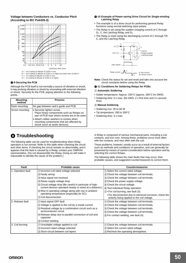
50
Voltage between Conductors vs. Conductor Pitch (According to IEC Pub326-3)
G-9 Securing the PCB
Although the PCB itself is not normally a source of vibration or shock, it may prolong vibration or shock by resonating with external vibration or shock. Securely fix the PCB, paying attention to the following points.
G-10 Example of Power-saving Drive Circuit for Single-winding Latching Relay
• The example is of a drive circuit for performing general Relay functions using normal switching input pulses.
• The Relay is set using the sudden charging current of C through D1, C, the Latching Relay, and D2.
• The Relay is reset using the discharging current of C through TR, C, and the Latching Relay.
Note: Check the status for set and reset and take into account the circuit constants before using the Relay.
G-11 Conditions for Soldering Relays for PCBs
A Automatic Soldering
• Solder temperature: Approx. 250°C (approx. 260°C for DWS)• Soldering time: 5 s max. (for DWS, 2 s first time and 3 s second
time)
B Manual Soldering
• Soldering iron: 30 to 60 W• Tip temperature: 280 to 300°C• Soldering time: 3 s max.
H TroubleshootingThe following table can be used for troubleshooting when Relay operation is not normal. Refer to this table when checking the circuit and other items. If checking the circuit reveals no abnormality, and it appears that the fault is caused by a Relay, contact your OMRON representative. (Do not disassemble the Relay. Doing so will make it impossible to identify the cause of the problem.)
A Relay is composed of various mechanical parts, including a coil, contacts, and iron core. Among these, problems occur most often with the contacts, and next often with the coil.
These problems, however, mostly occur as a result of external factors such as methods and conditions of operation, and can generally be prevented by means of careful consideration before operation and by selecting the correct Relays.
The following table shows the main faults that may occur, their probable causes, and suggested countermeasures to correct them.
Mounting method
Process
Rack mounting No gap between rack's guide and PCB
Screw mounting • Securely tighten screw.Place heavy components such as Relays on part of PCB near where screws are to be used.
• Attach rubber washers to screws when mounting components that are affected by shock (such as audio devices).
1007050
3020
200
300
1,000
2,000
3,000
500
700
0.1 0.2 0.3 0.5 0.71.0 2 3 5 10
C
A
D
B
A = w/o coating at altitude of 3,000 m max.B = w/o coating at altitude of 3,000 m or higher but lower than 15,000 mC = w/ coating at altitude of 3,000 m max.D = w/ coating at altitude of 3,000 m or higher
Rat
ed v
olta
ge c
ondu
ctor
s (V
dc)
Conductor pitch (mm)
Coil for Single-winding Latching Relay
Input signal
Relay current is: Set currentiR: Reset current
Fault Probable cause Countermeasures
1. Operation fault A Incorrect coil rated voltage selectedBFaulty wiringC Input signal not receivedDPower supply voltage dropECircuit voltage drop (Be careful in particular of high-
current devices operated nearby or wired at a distance.)FRise in operating voltage along with rise in ambient
operating temperature (especially for DC)GCoil disconnection
ASelect the correct rated voltage.BCheck the voltage between coil terminals.CCheck the voltage between coil terminals.DCheck the power supply voltage.ECheck the circuit voltage.FTest individual Relay operation.G • For coil burning, see fault (3).
• For disconnection due to electrical corrosion, check the polarity being applied to the coil voltage.
2. Release fault A Input signal OFF faultBVoltage is applied to the coil by a sneak current CResidual voltage by a combination circuit such as a
semiconductor circuitDRelease delay due to parallel connection of coil and
capacitorEContact welding
ACheck the voltage between coil terminals.BCheck the voltage between coil terminals.CCheck the voltage between coil terminals.DCheck the voltage between coil terminals.EFor contact welding, see fault (4).
3. Coil burning AUnsuitable voltage applied to coilB Incorrect rated voltage selectedCShort-circuit between coil layers
ACheck the voltage between coil terminals.BSelect the correct rated voltage.CRecheck the operating atmosphere.

51
Precautions for Correct Use of Terminal RelaysRefer to Safety Precautions for each product for specific precautions for that product.
MountingHeat generated by the relays must be considered when mounting relays side-by-side.
Space must be provided between the relays or other methods must be taken to maintain the relays' ambient temperature at 55°C or lower (80°C for the G3S4).
Relay Replacement• Use the P6B-Y1 Removal Tool for the
G6B-4CB, the G6B-4@@ND, and the G3S4 as shown in the diagram.
• Use the Removal Tool connected to the Terminal Relay for the G6D-F4B/-4B and the G3DZ-F4B/-4B.
• Be sure to turn OFF the power before replacing a relay.
• Relays must be inserted straight onto the socket connector pins to ensure proper connection.
• G6B-48BND relays (high reliability) are connected directly to boards to increase reliability and the relays are thus not replaceable.
• Do not use relays together that are different to one another in voltage.
WiringBe sure to connect the input terminals with the correct polarity. G3S4-D relay output terminals also have polarity that needs to be connected correctly.
Coil Voltage• Be sure not to impose voltage exceeding the permissible voltage
on the coil continuously.
• Do not use the relays when other inductive loads are connected in parallel with the coil input or when there are surges during power supply because the built-in diodes used to absorb surge may be destroyed.
Handling• Do not drop, shock, or vibrate the Relay excessively or apply
excessive force to the terminals.• Make sure that all the Relays are properly mounted before use.
Screw Tightening Torque• Tighten each terminal screw to a torque described below.
M3 terminal screw: 0.4 to 0.56 N·m.M3.5 terminal screw: 0.78 to 1.18 N·m.
• Tighten each mounting screw to a torque of 0.59 to 0.98 N·m.
Installation EnvironmentDo not install the Unit in the following locations. Otherwise, damage to the Unit may result or the Unit may malfunction.
• Locations subject to direct sunlight.• Locations subject to an ambient temperature that exceeds the
ambient operating temperature range.• Locations subject to relative humidity that exceeds the ambient
operating humidity range or locations subject to temperature changes resulting in condensation.
• Locations subject to corrosive or inflammable gas.• Locations subject to excessive dust, salinity, or metal powder.• Locations subject to vibration or shock affecting the Unit.• Locations subject to water, oil, or chemical sprayed on the Unit.
Disassembly, Repair, and ModificationDo not disassemble, repair, or modify the Relay. Otherwise, an electric shock may result or the Relay may malfunction.
4. Contact welding AExcessive device load connected (insufficient contact capacity)
BExcessive switching frequencyCShort-circuiting of load circuitDAbnormal contact switching due to hummingEExpected service life of contacts reached
ACheck the load capacity.BCheck the number of switches.CCheck the load circuits.DFor humming, see fault (7).ECheck the contact ratings.
5. Contact failure AOxidation of contact surfacesBContact abrasion and agingCTerminal and contact displacement due to faulty handling
A • Recheck the operating atmosphere.• Select the correct Relay.
BThe expected service life of the contacts has been reached.
CBe careful of vibration, shock, and soldering operations.
6. Abnormal contact consumption
AUnsuitable Relay selectionB Insufficient consideration of device load (especially
motor, solenoid, and lamp loads)CNo contact protection circuitD Insufficient withstand voltage between adjacent contacts
ASelect the correct Relay.BSelect the correct devices.CAdd a circuit such as a spark quenching circuit.DSelect the correct Relay.
7. Humming A Insufficient voltage applied to coilBExcessive power supply ripple (DC)C Incorrect coil rated voltage selectedDSlow rise in input voltageEAbrasion in iron coreFForeign material between moveable iron piece and iron
core
ACheck the voltage between coil terminals.BCheck the ripple percentage.CSelect the correct rated voltage.DMake supplemental changes to circuit.EThe expected service life has been reached.FRemove the foreign material.
Fault Probable cause Countermeasures
+
−
Do Not Use the Following Circuit
Inductive load
L G6B Coil
Coil surge current absorption diode

52
Mounted Relays
Note: 1. The G6B-48BND Relay cannot be replaced.2. Make sure the socket voltage specification matches the
relay voltage specification.3. Do not use relays together that have different voltage
specifications.
Terminal relay model Mounted relay model
G6D-4B/-F4B G6D-1A-ASI
G3DZ-4B/-F4B G3DZ-2R6PL
G6B-4CB G6B-2114P-US-P6B
G6B-4BNDG6B-4FB1NDG6B-4FPND
G6B-1114P-FD-US-P6B
G6B-47BND G6B-1174P-FD-US-P6B

53
Q&A for General-purpose RelaysWhat is a twin-contact relay model suitable for switching minute loads?
The highly reliable crossbar twin contact or twin contact relays are recommended for switching minute loads.
Series Suitable for Minute Loads
Crossbar twin contacts: G2A Series, MY4Z-CBG Series
Twin contacts: MY4Z Series, MK@ZP Series
Is the switching capacity doubled if two relays contacts are connected in parallel?
No.The two contacts are not always going to turn ON/OFF at the same time (there may be a slight delay) so one contact will bear the full load momentarily.
Do the operating and release times include bounce time.
No.Operating time: The time from when power is supplied to
the coil until the NO contact (make contact) turns ON.
Release time: The time from when the coil turns OFF and the NO contact (make contact) turns OFF (or, for transfer contacts, until the NC contact is reached).
What is the value in parentheses for models with the coil voltage listed as “100/(110) VAC”?
“100/(110) VAC” indicates that the coil has 3 ratings.
3 ratings100 VAC 50 Hz100 VAC 60 Hz110 VAC 60 Hz
If the specification has “100/110 VAC,” the coil has 4 ratings, i.e., it also has 110 VAC 50 Hz.The MY and LY are examples of Relays with 4 ratings.
How should we view contact reliability in minute load ranges?
The contact resistance of contacts sometimes becomes a problem when switching minute loads. Sometimes contacts recover during the next operation even if there is random high contact resistance. The contact resistance may also be increased by the generation of film on the contacts.
Whether or not the contact resistance will cause a problem in the circuit used should be the factor used to determine if a contact resistance value constitutes a failure or not. For this reason, only the initial value is specified as the reference for contact resistance failure. Failure rates are expressed as P levels (reference values) with the minimum applicable load as a guide.
Some relay contacts are suitable for minute loads and some are not.
Q1
A1
Q2
A2
Load
Relay
Q3
A3
OFF
ON
OFF
ON
OFF
ON
Release time
Operating time
Bounce time
Bounce time
Release time for relays with NO contacts only
Coil
NO contact
NC contact
Q4
A4
Q5
A5

54
Reference Material for General-purpose Relays
Influence of External Conditions, Environment, and Atmosphere on Relays
Coils
Relationship with Power1. For a DC Relay, the relationship is as follows:
2. For an AC Relay, coil impedance must be taken into account because it is affected by the coil inductance.The coil impedance varies with the frequency. Suppose the characteristics at 60 Hz are 100%, using the same Relay at 50 Hz will produce the characteristics shown in the following table. These values will depend on the type of Relay. Check the values before using the Relay.
3. Be careful of the following points: DC Relays, such as Keep Relays and Relays with built-in operation indicators or surge-absorbing diodes, have polarity. If the Relay is connected incorrectly, elements may be destroyed or malfunction.Applying a DC voltage to an AC Relay will cause the coil to heat. This may lead to burning. Applying an AC voltage to a DC Relay will cause the armature to vibrate and the Relay will not operate properly.
Relationship with TemperatureTemperature changes affect the resistance of the copper wires used for coils by approximately 0.4% per °C. This directly affects the Relay characteristics because the coil current, which generates the attractive force of an electromagnet, changes. The effect of temperature on the operating characteristics (such as the must-operate voltage and must-release voltage) of an AC Relay is smaller because the ratio of DC resistance of the coil to the coil impedance is small.
Changes in coil resistance also affect the coil temperature for DC Relays. This is because a change in coil current causes the amount of power consumption to change. The value of temperature rise changes according to the rate of change in the coil current due to changes in the temperature. A typical example is shown in the following figure.
Definition of Ambient Temperature
The temperature inside the box increases because of heat generated by the Relays and other devices. The ambient temperature that must be used is the temperature inside the box near the Relay.
Electrolytic CorrosionIf the Relay coil is not in an operating state, exposure to high temperatures or high humidity when there is a potential difference between the coil and other metals such as the core may cause the copper wire coil winding to corrode. The corrosion is caused by ionized current passing between the metals when the insulation between them is insufficient.
This can be made analogous to the process of creating metal plating. The effect is accelerated when acid or base is involved.
Not a lot of attention has been paid to this effect in the past; however, good quality plastic has been developed for spooling recently, and insulation materials such as polyurethane, polyester, polyamide, and Fluorine Resin have also been developed for the winding. These modern plastics reduce the effect of electrolytic corrosion.
To prevent electrolytic corrosion, avoid storage in locations with high temperature or high humidity. Thought must be given to the circuit layout, such as positioning the switch so that the winding is not subject to a constant positive voltage, or create a positive ground. Good and bad examples are shown on the right.
Rated current, Power consumption and temperature rise
Approx. 117%
Must-operate current Approx. 100%
Must-operate voltage, must-release voltage Approx. 85%
Coil current = Applied voltageCoil resistance
The percentage of coil temperature rise caused by a 20°C increase in ambient temperature.Change in coil temperature caused by change in ambient temperature.
120
110
100
90
80
70
60
−10 0 10 20 30 40 50 60
Exposed Relay
Relay enclosed in case (plug-in type)
Ambient temperature (°C)
Rat
e of
tem
pera
ture
ris
e
∗
∗
Box
Relay Relay Relay
Ta (near the Relay)
Fe
− +Cu
− −
+
−+

55
Operating Time
Relationship between Shape of Relay and Operating TimeThe operating time of the Relay is determined by the coil time constant, delay time due to the moment of inertia, and the contact switching time. These values differ with the shape of the Relay. For example, Relays with a large gap between the core and the armature or Relays that have electromagnets made from materials with a large magnetic resistance, have small inductance values, and the time constant is small. However, this weakens the attractive force, hence more time is required to attract the armature. This phenomenon often occurs in DC operation. The magnetic attraction is weakened because it is inversely proportional to the square of the distance between the core and the armature. For High-speed Relays, the gap is made smaller and material with high magnetic permeability is used to reduce amount of coil winding.
In AC operation, a current larger than the rated current is drawn when power is supplied. The shape of the Relay is not as relevant as it is for DC operation.
The moment of inertia has an indirect driving force that prevents large loads on the armatures when they begin to move.
Movement of the armatures practically dictates the contact switching time. For this reason, the loads and the attractive force must be balanced so that the armature movement is as small as possible, and it moves smoothly through all stages of the movement. Contact bounce is affected by factors such as the moving speed of the armature, quality of the moving parts, and springiness of the contact springs.
Generally, the shape of the contact spring, the contact segment, or the structure of the stopper is designed to dampen the shocks from the movements.
Relationship between Voltage/Current Applied to Coils and Operating TimeThe Relay operating time is affected by the voltage/current applied to the coils.
As shown in the following figure, when a voltage slightly higher than the must-operate voltage is applied, the time taken for the coil current to reach the must-operate current, the time taken for the moving parts to overcome inertia and start moving, and the time taken for the attractive force to overcome the weight of the loads and switch the contact, all become longer, therefore the operating time is considerably extended.
When a voltage much higher than the must-operate voltage is applied, all the times become shorter, and therefore the operating time becomes faster.
The relationship between the voltage applied to the coil and operating time is as explained above, however, the voltage applied to the coil also affects other characteristics. This is why a rated coil voltage is specified.
Relationship between Applied Coil Voltage/Current and Operating Time
Relationship between Coil Temperature and Operating TimeWhen the Relay temperature changes, the springiness of the Relay contact spring, the amount of friction, and the coil resistance, change. Of these, the coil resistance has the largest impact on the operating time. As explained in the section on the principles of operation, the movement of the electromagnet is related to the current. The current of DC electromagnets can be expressed by the following equation.
i: Coil currentR: Coil resistanceE: Voltage applied to coilϒ: L/R coil time constantt: Time elapsed since voltage was applied to coil
At this point, if the coil temperature increases, the coil resistance increases by 0.4% per °C as stated before. This increases R (DC coil resistance) of the coil time constant (L/R), therefore reducing the waiting time of the contacts and shortening the operating time. On the other hand, if the coil resistance increases, the coil current decreases. This extends the operating time of the DC Relay. The figure shows the change in operating time according to coil temperature for voltage and current operation.
Large Relays that have an operating time of a few 10 ms do not change a lot even if the temperature changes. Small Relays that have an operating time of less than 10 ms tend to change more when the temperature changes.
Relationship between Coil Temperature and Operating Time
0
Ope
ratin
g tim
e
Must-operate voltage (current)
Rated voltage (current)
Voltage (current) applied to coil
i = ER
1−e tϒ
−

56
Operating Environment
Silver MigrationSilver migration describes a phenomenon that occurs when certain humidity and oxidation-reduction conditions exist, and then DC voltage is applied to silver electrodes for an extended period of time. This phenomenon causes the insulation to deteriorate and occasionally causes short circuit problems.
Silver Migration
Enlarged Photograph of Silver Migration
It is not well known what causes silver migration, or what conditions accelerate silver migration. However, the following points can be made.
General-purpose Relays made by OMRON do not use silver plated terminals and will not cause silver migration.
Cat WhiskersWhen a plated part is stored for an extended period of time, needle-like crystals form on the surface. These crystals are called cat whiskers because of their shape. Depending on the length of the crystals, they may cause short circuit problems.
The reason why cat whiskers form is not completely understood. However, it is said that they will form easily when brass or zinc is used as the base material and tin or zinc is used for the plating.
Example of Whisker Formation
General-purpose Relays made by OMRON have solder plating or special zinc plating to guard against the formation of whiskers. When designing parts, print boards, or patterns, keep in mind about the use of zinc and brass, and allocate enough space for the insulation.
High-humidity RelaysWhen shipping Relays through tropical zones, regardless whether it is just the Relays or the Relays are built in to other devices, they will be exposed to high temperatures and high humidity.
To protect the metallic material from this kind of environment, High-humidity Relays with special external specifications have been developed.
Contact Deterioration Due to EnvironmentEven if Relays are not used and just stored, the degradation of the contacts may progress. This is due to the influences of sulfur and chlorine contained in the atmosphere, as shown in the following table. If the Relay is to be stored for such a long period as years, it is
recommended to perform a conductivity test when the Relay is actually used, or to use Relays with gold-plated or gold-clad
160
140
180
200
120
100
80
60
0 20 40 60 80 100
Coil temperature (°C)
Current operation
Voltage operation
Mov
emen
t var
iatio
n ra
te (
% fo
r +
20°C
)
DC voltage
Ag
Silver plated terminal
Insulation with high absorbency (e.g., phenol resin)
Conditions that Cause Silver Migration
Conditions that Accelerate Silver Migration
Usage of silver • Applied voltage is high and insulation is thin (high potential frequency).
• High water absorption rate of insulation material.
• Oxidation-reduction gases such as (SO2, H2S, NH3)
Applying DC voltage for an extended period of time
Insulation with high absorbency of humidity
Usage in high-temperature or high-humidity environments

57
contacts.
Contacts
Inherent Characteristics of ContactsThe desirable features of contacts, purely from a usage point of view, are that they have stable characteristics (such as contact resistance) and that they have a long life. To meet these conditions, contact follow and contact pressure are important aspects.
Contact pressure is normally 5 to 50 g for general-use silver and platinum, and 3 to 10 g for precious metals such as gold, silver, and palladium. The pressure is smaller for precious metals because the switching capacity is smaller and it is relatively robust against environmental influences.
Contact follow requires the contacts to be touching even if the contacts are somewhat worn out. It is closely related to the contact pressure. The product of the two is the workload of the contacts. For a certain workload, the contact pressure can be increased or the contact follow can be increased to change the contactibility.
For example, when the contact pressure is large and the contact follow is small, initially it will appear stable, but as the contact begins to wear out, the contact pressure will rapidly drop and eventually the contacts will not touch at all.
On the other hand, if the contact pressure is small and the contact follow is large, the contact resistance may increase, or it may have difficulty breaking down the film. Therefore, good Relays must have a reasonable balance between contact follow and contact pressure.
Contact resistance can be regarded as a combination of concentrated resistance and boundary resistance.
At first glance, the contact looks like it is touching the whole surface. However, depending on the shape and the roughness of the surface of the contact, it actually touches only on a single or multiple points. Current flow is concentrated at these contact points and the generated resistance is the concentrated resistance.
As described by the structure and principle of Relays formula, the contact stiffness, contact pressure, and the inherent resistance of contact material are related. A model of the contacting parts is shown below. The contact is made over an extremely small area. Current is concentrated in this extremely small area.
A measured example of the relationship between contact pressure and contact resistance is also shown below.
Current Distribution at Connection Part
Contact Pressure and Contact Resistance
If contacts are exposed to the air, the formation of oxidation and sulphurization films is unavoidable. Resistance caused by these films is called boundary resistance (film resistance).
Generally, the concentrated resistance takes up a large proportion of the contact resistance before the contact is used. However, as the contact is used, arcing and mechanical friction begin to wear it out, and the proportion of the boundary resistance increases. The proportion depends on the switching frequency. Contact surfaces subject to higher switching frequencies are relatively clean and the boundary resistance is low. Contacts with low switching frequencies generate films with fairly high boundary resistance.
The contact resistance of a Relay is listed in catalogs but it is only a provision of the initial value determined using a standard testing method. The actual contact resistance must be suitable for the application device and is determined by its tolerance to load impedance. Excluding special cases, such as the transmission of sound currents where distortion and attenuation becomes a problem, the contact resistance has a tolerance of 1% to 5% of the load impedance.
Area Detected elements
Results of observation of contact surface (Ag contacts left for 12 months)
Chemical plant
Ag, S Almost uniform and dense corrosive substances were observed on the entire surface of the contacts. As a result of analysis, Ag2S was detected.
Steal mill Ag, S Irregular projections and recesses were observed and pillars of crystal were dispersed. As a result of analysis, Ag2S was detected.
Highway Ag, S, CL Circular crystals were sporadically observed. Ag2S was extremely thin at the white portions, approx. 20 A.
Chemical plant
× 5,000
Steal mill
× 5,000
Highway
× 5,000
Current flux
Contacting surface
100
50
20100Contact pressure (g)
Sample 4
Con
tact
res
ista
nce
(mΩ
)

58
Load Conditions and ContactsMost of the problems that occur to a Relay are caused by the contactibility of the contacts. Load conditions also influence the type of problem that occurs. Load conditions can be grouped into micro-energy level (dry circuit), mid-energy level, and high-energy level conditions.
The micro-energy level in a strict sense is a load condition of a mechanical contact circuit, where the status of the contact is not affected by heat or discharge. In reality, however, the status of the contact does not change even when a reasonable voltage is applied, so this load condition is included in the definition.
The voltage level at which the status of the contact remains unaffected is called the softening voltage. It is 0.09 V for silver, 0.08 V for gold, 0.25 V for platinum, and 0.6 V for tungsten.
The mid-energy level is a load condition where a there is a mild discharge effect. It is from the softening voltage to where arc discharge begins. Flashover begins at 12 V for silver, 15 V for gold, 17.5 V for platinum, 15 V for tungsten, and 11 V for 10% palladium silver alloy.
The high-energy level describes voltages that exceed the arc discharge voltage.
Problems Specific to ContactsParticular problems can occur depending on how the contacts are used. The following describes some of them.
1. Abnormal Corrosion from Load Switching
This problem occurs when arcing due to load switching bonds nitrogen and oxygen in the atmosphere together to form HNO3, which corrodes metallic material (nitric acid corrosion).
Example of nitric acid corrosion
The following countermeasures may be effective.
(1) Reduce the amount of arcing that occurs during load switching by creating an arc reduction circuit.
(2) Reduce the switching frequency to eliminate continual arcing.
(3) Reduce the humidity in the atmosphere.
2. Coherer Effect
If there is a film on the surface of a contact and the contacts are touching, the film breaks down and the contact resistance drops rapidly when the contact voltage exceeds a certain value.
3. Thermoelectromotive Force
Relay contacts are made from a combination of metals (such as silver and copper alloy) depending on their function. The temperature varies between the junctions depending on the distance from the heat emitting body (such as the coil) and depending on the path of heat conduction. As a result, thermoelectromotive force from a few to a few tens of µV is created between the contact terminals. Care must be taken especially when handling micro signals.
A Latching Relay (Keep Relay) can be used to shorten the time required for current to pass through the coil, thus limiting the amount of heat generated by the coil and reducing the thermoelectromotive force. A Relay with small thermoelectromotive force can also be used. (Relay with especially designed contact conduction section.)
Contactibility under Load ConditionsThe effect on the contact is completely different between the micro-energy level and high-energy level load conditions. The micro-energy level has little contact wear but the existence of contact faults becomes a problem. Contact wear, welding, and transfer become problems in the high-energy level load condition.
At the micro-energy level, the cleanliness of the contacts is the most important aspect. If any non-conductive material or film is stuck to the contacts, it will cause contact failure.
Non-conductive material may be dust, such as sand and fiber, but micro-load Relays have relatively small contact wipes and pressure so any particles stuck to the contact surface will cause contact faults. This is a problem for all Relays regardless of the contact material, which makes it difficult to select and use the right Relay. Formation of a non-conductive film may be caused by the type of material the Relay is made from, or the surrounding environment. The film depends on the moisture in the air, oily or oxidized substances, organic gases emitted from other Relays or structures, exhaust gas from vehicles, smoke from factories, flux of the soldering, and fingerprints of the assembly worker. Therefore, strategies are required for the structure of the Relay, the material of the contact, and ambient conditions.
Generic silver contacts oxidize and sulphurize easily. Oxidation films do not affect the contacts a lot, but sulphurization films have a large effect. For this reason, precious metals that do not sulphurize easily are used. Normally, palladium, gold, or platinum gold is combined with silver to form silver alloys used for the contacts. Contacts made from platinum alloys generate insulating powder (brown powder) due to the unsaturated organic gas that is emitted from benzene and gasoline. Gold does not form any films and the contactibility remains stable, but it is soft, so it bends under low pressure. It cannot be used by itself, so palladium may be used to create a double-layer contact where the top layer is a gold film.
In conditions where discharge occurs even with only micro-loads, the contact may oxidize or combustible gases in the atmosphere may burn and create a carbonized film. Carbonized films are not perfect insulators, so the resistance may reach a few ten to a few hundred ohms.
At the high-energy level, flashover continuously generates large energy. This may cause the contact to melt when it is switching, or the contact to wear out from scattering of metallic vapor. It may also suffer from problems such as transfer of metallic powder from one contact to the other, or welding where the contacts melt and bond together when power is supplied.
DC voltages and DC currents do not have points that cross at zero like there is for an AC voltage and current. So even for fairly small loads, arcing may continue for a long time.
Under these load conditions, adherence of metallic powder and carbonizing of the insulator may deteriorate the insulation. For this reason, certain types of insulation material and shapes are chosen.
The type of damage that occurs to the contacts depends on the type of load. Loads such as transformers, motors, and lamps cause large inrush currents and can cause welding of the contacts. Lamps, motors, transformers, and solenoids cause currents of a few to multiples of ten times the current.
Inductive loads such as motors, transformers, and solenoids cause large reverse currents when power is shut off. The voltages reach 4 to 20 times the normal voltage. This may wear out the contacts or damage the loads.
Waveform of Induction Motor Starting Current

59
Waveform of AC Solenoid Starting Current
Waveform of Lamp Starting Current
In the interest of product improvement, specifications are subject to change without notice.
ALL DIMENSIONS SHOWN ARE IN MILLIMETERS.
To convert millimeters into inches, multiply by 0.03937. To convert grams into ounces, multiply by 0.03527.