technical guidelines for the estimation of greenhouse gas...
TRANSCRIPT
National Greenhouse and Energy Reporting Scheme MeasurementTechnical Guidelines for the estimation of emissions by facilities in AustraliaApplies to the estimation of emissions in the 2015-16 reporting year
August 2016

Published by the Department of the Environment and Energy
http://www.environment.gov.au
ISSN 2202-3348
© Commonwealth of Australia 2016
This work is licensed under the Creative Commons Attribution 3.0 Australia Licence. To
view a copy of this license, visit http://creativecommons.org/licenses/by/3.0/au.
The Department of the Environment and Energy asserts the right to be recognised as
author of the original material in the following manner:
or
© Commonwealth of Australia (Department of the Environment and Energy) 2016.
IMPORTANT NOTICE – PLEASE READ
This document is produced for general information only and does not represent a statement
of the policy of the Commonwealth of Australia. The Commonwealth of Australia and all
persons acting for the Commonwealth preparing this report accept no liability for the
accuracy of or inferences from the material contained in this publication, or for any action as
a result of any person’s or group’s interpretations, deductions, conclusions or actions in
relying on this material.
August 2016
2

Contents
Chapter 1—General 30
Part 1.1—Preliminary
Division 1.1.1—Overview
1.4 Overview—methods for measurement
1.5 Overview—energy
1.6 Overview—scope 2 emissions
1.7 Overview—assessment of uncertainty
Division 1.1.2—Definitions and interpretation
1.9 Interpretation
1.9A Meaning of separate instance of a source
1.9B Meaning of separate occurrence of a source
1.10 Meaning of source
Part 1.2—General
1.11 Purpose of Part
Division 1.2.1—Measurement and standards
1.12 Measurement of emissions
1.13 General principles for measuring emissions
1.14 Assessment of uncertainty
1.15 Units of measurement
1.16 Rounding of amounts
1.17 Status of standards
3
Division 1.2.2—Methods
1.18 Method to be used for a separate occurrence of a source
1.18A Conditions—persons preparing report must use same method
1.19 Temporary unavailability of method
Division 1.2.3 Requirements in relation to carbon capture and storage
1.19A Meaning of captured for permanent storage
1.19B Deducting carbon dioxide that is captured for permanent storage
1.19C Capture from facility with multiple sources jointly generated
1.19D Capture from a source where multiple fuels consumed
1.19E Measure of quantity of carbon dioxide captured
1.19F Volume of carbon dioxide stream—criterion A
1.19G Volume of carbon dioxide stream—criterion AAA
1.19H Volumetric measurement—carbon dioxide stream not super-compressed
1.19I Volumetric measurement—super-compressed carbon dioxide stream
1.19J Gas measuring equipment—requirements
1.19K Flow devices—requirements
1.19L Flow computers—requirements
1.19M Gas chromatographs
1.19N Volume of carbon dioxide stream—criterion BBB
Part 1.3—Method 4—Direct measurement of emissions
Division 1.3.1—Preliminary
1.20 Overview
Division 1.3.2—Operation of method 4 (CEM)
Subdivision 1.3.2.1—Method 4 (CEM) 60
1.21 Method 4 (CEM)—estimation of emissions
4

1.21A Emissions from a source where multiple fuels consumed
Subdivision 1.3.2.2—Method 4 (CEM)—use of equipment 64
1.22 Overview
1.23 Selection of sampling positions for CEM equipment
1.24 Measurement of flow rates by CEM
1.25 Measurement of gas concentrations by CEM
1.26 Frequency of measurement by CEM
Division 1.3.3—Operation of method 4 (PEM)
Subdivision 1.3.3.1—Method 4 (PEM) 67
1.27 Method 4 (PEM)—estimation of emissions
1.27A Emissions from a source where multiple fuels consumed
1.28 Calculation of emission factors
Subdivision 1.3.3.2—Method 4 (PEM)—use of equipment 71
1.29 Overview
1.30 Selection of sampling positions for PEM equipment
1.31 Measurement of flow rates by PEM equipment
1.32 Measurement of gas concentrations by PEM
1.33 Representative data for PEM
Division 1.3.4—Performance characteristics of equipment
1.34 Performance characteristics of CEM or PEM equipment
Chapter 2—Fuel combustion 74
Part 2.1—Preliminary
2.1 Outline of Chapter
5

Part 2.2—Emissions released from the combustion of solid fuels
Division 2.2.1—Preliminary
2.2 Application
2.3 Available methods for estimating emissions of carbon dioxide, methane and
nitrous oxide
Division 2.2.2—Method 1—emissions of carbon dioxide, methane and nitrous oxide from solid fuels
2.4 Method 1—solid fuels
Table 2.2.2: Emission and energy content factors — solid fuels and certain coal-based products
Division 2.2.3—Method 2—emissions from solid fuels
Subdivision 2.2.3.1—Method 2—estimating carbon dioxide using default oxidation factor 83
2.5 Method 2—estimating carbon dioxide using oxidation factor
Table 2.2.3 Analysis of solid fuels: standards and frequency of analysis for
energy, carbon, moisture and ash
Subdivision 2.2.3.2—Method 2—estimating carbon dioxide using an estimated oxidation factor92
2.6 Method 2—estimating carbon dioxide using an estimated oxidation factor
Subdivision 2.2.3.3—Sampling and analysis for method 2 under sections 2.5 and 2.6 94
2.7 General requirements for sampling solid fuels
2.8 General requirements for analysis of solid fuels
2.9 Requirements for analysis of furnace ash and fly ash
2.10 Requirements for sampling for carbon in furnace ash
2.11 Sampling for carbon in fly ash
Division 2.2.4—Method 3—Solid fuels
2.12 Method 3—solid fuels using oxidation factor or an estimated oxidation factor
6
Division 2.2.5—Measurement of consumption of solid fuels
2.13 Purpose of Division
2.14 Criteria for measurement
2.15 Indirect measurement at point of consumption—criterion AA
2.16 Direct measurement at point of consumption—criterion AAA
2.17 Simplified consumption measurements—criterion BBB
Part 2.3—Emissions released from the combustion of gaseous fuels
Division 2.3.1—Preliminary
2.18 Application
2.19 Available methods
Division 2.3.2—Method 1—emissions of carbon dioxide, methane and nitrous oxide
2.20 Method 1—emissions of carbon dioxide, methane and nitrous oxide
Table 2.3.2A Emission and energy content factors — gaseous fuels
Table 2.3.2B Emissions and energy content factors — gaseous fuels for transport energy purposes
Division 2.3.3—Method 2—emissions of carbon dioxide from the combustion of gaseous fuels
Subdivision 2.3.3.1—Method 2—emissions of carbon dioxide from the combustion of gaseous fuels 119
2.21 Method 2—emissions of carbon dioxide from the combustion of gaseous fuels
2.22 Calculation of emission factors from combustion of gaseous fuel
Subdivision 2.3.3.2—Sampling and analysis 122
2.23 General requirements for sampling under method 2
2.24 Standards for analysing samples of gaseous fuels
7

2.25 Frequency of analysis
Division 2.3.4—Method 3—emissions of carbon dioxide released from the combustion of gaseous fuels
2.26 Method 3—emissions of carbon dioxide from the combustion of gaseous fuels
Division 2.3.5—Method 2—emissions of methane from the combustion of gaseous fuels
2.27 Method 2—emissions of methane from the combustion of gaseous fuels
Division 2.3.6—Measurement of quantity of gaseous fuels
2.28 Purpose of Division
2.29 Criteria for measurement
2.30 Indirect measurement—criterion AA
2.31 Direct measurement—criterion AAA
2.32 Volumetric measurement—all natural gases
2.33 Volumetric measurement—super-compressed gases
2.34 Gas measuring equipment—requirements
2.35 Flow devices—requirements
2.36 Flow computers—requirements
2.37 Gas chromatographs—requirements
2.38 Simplified consumption measurements—criterion BBB
Part 2.4—Emissions released from the combustion of liquid fuels
Division 2.4.1—Preliminary
2.39 Application
2.39A Definition of petroleum based oils for Part 2.4
Subdivision 2.4.1.1—Liquid fuels—other than petroleum based oils and greases 140
2.40 Available methods
8

Subdivision 2.4.1.2—Liquid fuels—petroleum based oils and greases 141
2.40A Available methods
Division 2.4.2—Method 1—emissions of carbon dioxide, methane and nitrous oxide from liquid fuels other than petroleum based oils or greases
2.41 Method 1—emissions of carbon dioxide, methane and nitrous oxide
Table 2.4.2A Emission and energy content factors — liquid fuels and certain
petroleum-based products for stationary energy purposes
Table 2.4.2B Emissions and energy content factors — fuels for transport energy purposes
Division 2.4.3—Method 2—emissions of carbon dioxide from liquid fuels other than petroleum based oils or greases
Subdivision 2.4.3.1—Method 2—emissions of carbon dioxide from liquid fuels other than petroleum based oils or greases 147
2.42 Method 2—emissions of carbon dioxide from the combustion of liquid fuels
2.43 Calculation of emission factors from combustion of liquid fuel
Subdivision 2.4.3.2—Sampling and analysis 148
2.44 General requirements for sampling under method 2
2.45 Standards for analysing samples of liquid fuels
2.46 Frequency of analysis
Division 2.4.4—Method 3—emissions of carbon dioxide from liquid fuels other than petroleum based oils or greases
2.47 Method 3—emissions of carbon dioxide from the combustion of liquid fuels
Division 2.4.5—Method 2—emissions of methane and nitrous oxide from liquid fuels other than petroleum based oils or greases
2.48 Method 2—emissions of methane and nitrous oxide from the combustion of
liquid fuels
9
Table 2.4.5A Fuel combustion — liquid fuels for transport energy purposes for post-2004 vehicles
Table 2.4.5B Fuel combustion — liquid fuels for transport energy purposes for certain trucks
Division 2.4.5A—Methods for estimating emissions of carbon dioxide from petroleum based oils or greases
2.48A Method 1—estimating emissions of carbon dioxide using an estimated
oxidation factor
2.48B Method 2—estimating emissions of carbon dioxide using an estimated
oxidation factor
2.48C Method 3—estimating emissions of carbon dioxide using an estimated
oxidation factor
Division 2.4.6—Measurement of quantity of liquid fuels
2.49 Purpose of Division
2.50 Criteria for measurement
2.51 Indirect measurement—criterion AA
2.52 Direct measurement—criterion AAA
2.53 Simplified consumption measurements—criterion BBB
Part 2.5—Emissions released from fuel use by certain industries
2.54 Application
2.55 Application
2.56 Methods
2.57 Application
2.58 Methods
Division 2.5.3—Energy—petrochemical production
2.59 Application
10
2.60 Available methods
2.61 Method 1—petrochemical production
2.62 Method 2—petrochemical production
2.63 Method 3—petrochemical production
Part 2.6—Blended fuels
2.64 Purpose
2.65 Application
2.66 Blended solid fuels
2.67 Blended liquid fuels
Part 2.7—Estimation of energy for certain purposes
2.68 Amount of energy consumed without combustion
2.69 Apportionment of fuel consumed as carbon reductant or feedstock and energy
2.70 Amount of energy consumed in a cogeneration process
2.71 Apportionment of energy consumed for electricity, transport and for stationary
energy
Appendix 2A Notes on Energy and Emission Factors
Chapter 3—Fugitive emissions 199
Part 3.1—Preliminary
3.1 Outline of Chapter
Part 3.2—Coal mining—fugitive emissions
Division 3.2.1—Preliminary
3.2 Outline of Part
11
Division 3.2.2—Underground mines
Subdivision 3.2.2.1—Preliminary 200
3.3 Application
3.4 Available methods
Subdivision 3.2.2.2—Fugitive emissions from extraction of coal 203
3.5 Method 1—extraction of coal
3.6 Method 4—extraction of coal
3.7 Estimation of emissions
3.8 Overview—use of equipment
3.9 Selection of sampling positions for PEM
3.10 Measurement of volumetric flow rates by PEM
3.11 Measurement of concentrations by PEM
3.12 Representative data for PEM
3.13 Performance characteristics of equipment
Subdivision 3.2.2.3—Emissions released from coal mine waste gas flared 207
3.14 Method 1—coal mine waste gas flared
3.15 Method 2—emissions of carbon dioxide from coal mine waste gas flared
3.15A Method 2—emissions of methane and nitrous oxide from coal mine waste gas
flared
3.16 Method 3—coal mine waste gas flared
Subdivision 3.2.2.4—Fugitive emissions from post-mining activities 214
3.17 Method 1—post-mining activities related to gassy mines
Division 3.2.3—Open cut mines
Subdivision 3.2.3.1—Preliminary 215
3.18 Application
3.19 Available methods
12
Subdivision 3.2.3.2—Fugitive emissions from extraction of coal 217
3.20 Method 1—extraction of coal
3.21 Method 2—extraction of coal
3.22 Total gas contained by gas bearing strata
3.23 Estimate of proportion of gas content released below pit floor
3.24 General requirements for sampling
3.25 General requirements for analysis of gas and gas bearing strata
3.25A Method of working out base of the low gas zone
3.25B Further requirements for estimator
3.25C Default gas content for gas bearing strata in low gas zone
3.25D Requirements for estimating total gas contained in gas bearing strata
3.26 Method 3—extraction of coal
Subdivision 3.2.3.3—Emissions released from coal mine waste gas flared 228
3.27 Method 1—coal mine waste gas flared
3.28 Method 2—coal mine waste gas flared
3.29 Method 3—coal mine waste gas flared
Division 3.2.4—Decommissioned underground mines
Subdivision 3.2.4.1—Preliminary 229
3.30 Application
3.31 Available methods
Subdivision 3.2.4.2—Fugitive emissions from decommissioned underground mines 231
3.32 Method 1—decommissioned underground mines
3.33 Emission factor for decommissioned underground mines
3.34 Measurement of proportion of mine that is flooded
3.35 Water flow into mine
3.36 Size of mine void volume
13

3.37 Method 4—decommissioned underground mines
Subdivision 3.2.4.3—Fugitive emissions from coal mine waste gas flared 234
3.38 Method 1—coal mine waste gas flared
3.39 Method 2—coal mine waste gas flared
3.40 Method 3—coal mine waste gas flared
Part 3.3—Oil and natural gas—fugitive emissions
Division 3.3.1—Preliminary
3.40A Definition of natural gas for Part 3.3
3.41 Outline of Part
Division 3.3.2—Oil or gas exploration
Subdivision 3.3.2.1—Preliminary 237
3.42 Application
Subdivision 3.3.2.2—Oil or gas exploration (flared) emissions 237
3.43 Available methods
3.44 Method 1—oil or gas exploration
3.45 Method 2—oil or gas exploration (flared carbon dioxide emissions)
3.45A Method 2A—oil or gas exploration (flared methane or nitrous oxide emissions)
3.46 Method 3—oil or gas exploration
Subdivision 3.3.2.3—Oil or gas exploration—fugitive emissions from system upsets, accidents and deliberate releases from process vents 241
3.46A Available methods
3.46B Method 4—vented emissions from well completions and well workovers
Division 3.3.3—Crude oil production
Subdivision 3.3.3.1—Preliminary 258
3.47 Application
14

Subdivision 3.3.3.2—Crude oil production (non-flared)—fugitive leak emissions of methane 258
3.48 Available methods
3.49 Method 1—crude oil production (non-flared) emissions of methane
3.50 Method 2—crude oil production (non-flared) emissions of methane
Subdivision 3.3.3.3—Crude oil production (flared)—fugitive emissions of carbon dioxide, methane and nitrous oxide 262
3.51 Available methods
3.52 Method 1—crude oil production (flared) emissions
3.53 Method 2—crude oil production
3.53A Method 2A—crude oil production (flared methane or nitrous oxide emissions)
3.54 Method 3—crude oil production
Subdivision 3.3.3.4—Crude oil production (non-flared)—fugitive vent emissions of methane and carbon dioxide 265
3.56A Available methods
Division 3.3.4—Crude oil transport
3.57 Application
3.58 Available methods
3.59 Method 1—crude oil transport
3.60 Method 2—fugitive emissions from crude oil transport
Division 3.3.5—Crude oil refining
3.61 Application
3.62 Available methods
Subdivision 3.3.5.1—Fugitive emissions from crude oil refining and from storage tanks for crude oil 273
3.63 Method 1—crude oil refining and storage tanks for crude oil
3.64 Method 2—crude oil refining and storage tanks for crude oil
15

Subdivision 3.3.5.2—Fugitive emissions from deliberate releases from process vents, system upsets and accidents 275
3.65 Method 1—fugitive emissions from deliberate releases from process vents,
system upsets and accidents
3.66 Method 4—deliberate releases from process vents, system upsets and
accidents
Subdivision 3.3.5.3—Fugitive emissions released from gas flared from the oil refinery 276
3.67 Method 1—gas flared from crude oil refining
3.68 Method 2—gas flared from crude oil refining
3.68A Method 2A—crude oil refining (flared methane or nitrous oxide emissions)
3.69 Method 3—gas flared from crude oil refining
Division 3.3.6—Natural gas production or processing, other than emissions that are vented or flared
3.70 Application
3.71 Available methods
3.72 Method 1—natural gas production and processing (other than emissions that
are vented or flared)
3.73 Method 2—natural gas production and processing (other than venting and
flaring)
Division 3.3.7—Natural gas transmission
3.74 Application
3.75 Available methods
3.76 Method 1—natural gas transmission
3.77 Method 2—natural gas transmission
Division 3.3.8—Natural gas distribution
3.78 Application
3.79 Available methods
16
3.80 Method 1—natural gas distribution
3.81 Method 2—natural gas distribution
Division 3.3.9—Natural gas production or processing (emissions that are vented or flared)
3.82 Application
3.83 Available methods
Subdivision 3.3.9.1—Fugitive emissions that result from deliberate releases from process vents, system upsets and accidents 295
3.84 Method 1—emissions from system upsets, accidents and deliberate releases
from process vents
Subdivision 3.3.9.2—Emissions released from gas flared from natural gas production and processing 296
3.85 Method 1—gas flared from natural gas production and processing
3.86 Method 2—gas flared from natural gas production and processing
3.86A Method 2A—natural gas production and processing (flared methane or nitrous
oxide emissions)
3.87 Method 3—gas flared from natural gas production and processing
Part 3.4—Carbon capture and storage—fugitive emissions
Division 3.4.1—Preliminary
3.88 Outline of Part
Division 3.4.2—Transport of captured carbon dioxide
Subdivision 3.4.2.1—Preliminary 301
3.89 Application
3.90 Available methods
Subdivision 3.4.2.2—Emissions from transport of carbon dioxide captured for permanent storage involving transfer 302
3.91 Method 1—emissions from transport of carbon dioxide involving transfer
17

Subdivision 3.4.2.2—Emissions from transport of carbon dioxide captured for permanent storage not involving transfer 302
3.92 Method 1—emissions from transport of carbon dioxide not involving transfer
Chapter 4—Industrial processes emissions 304
Part 4.1—Preliminary
4.1 Outline of Chapter
Part 4.2—Industrial processes—mineral products
Division 4.2.1—Cement clinker production
4.2 Application
4.3 Available methods
4.4 Method 1—cement clinker production
4.5 Method 2—cement clinker production
4.6 General requirements for sampling cement clinker
4.7 General requirements for analysing cement clinker
4.8 Method 3—cement clinker production
4.9 General requirements for sampling carbonates
4.10 General requirements for analysing carbonates
Division 4.2.2—Lime production
4.11 Application
4.12 Available methods
4.13 Method 1—lime production
4.14 Method 2—lime production
4.15 General requirements for sampling
4.16 General requirements for analysis of lime
4.17 Method 3—lime production
18
4.18 General requirements for sampling
4.19 General requirements for analysis of carbonates
Division 4.2.3—Use of carbonates for production of a product other than cement clinker, lime or soda ash
4.20 Application
4.21 Available methods
4.22 Method 1—product other than cement clinker, lime or soda ash
4.22A Method 1A—product other than cement clinker, lime or soda ash for use of
carbonates in clay materials
4.23 Method 3—product other than cement clinker, lime or soda ash
4.23A Method 3A—product other than cement clinker, lime or soda ash for use of
carbonates in clay materials
4.23B General requirements for sampling clay material
4.23C General requirements for analysing clay material
4.24 General requirements for sampling carbonates
4.25 General requirements for analysis of carbonates
Division 4.2.4—Soda ash use and production
4.26 Application
4.27 Outline of Division
Subdivision 4.2.4.1—Soda ash use 328
4.28 Available methods
4.29 Method 1—use of soda ash
Subdivision 4.2.4.2—Soda ash production 329
4.30 Available methods
4.31 Method 1—production of soda ash
4.32 Method 2—production of soda ash
19
4.33 Method 3—production of soda ash
Division 4.2.5—Measurement of quantity of carbonates consumed and products derived from carbonates
4.34 Purpose of Division
4.35 Criteria for measurement
4.36 Indirect measurement at point of consumption or production—criterion AA
4.37 Direct measurement at point of consumption or production—criterion AAA
4.38 Acquisition or use or disposal without commercial transaction—criterion BBB
4.39 Units of measurement
Part 4.3—Industrial processes—chemical industry
Division 4.3.1—Ammonia production
4.40 Application
4.41 Available methods
4.42 Method 1—ammonia production
4.43 Method 2—ammonia production
4.44 Method 3—ammonia production
Division 4.3.2—Nitric acid production
4.45 Application
4.46 Available methods
4.47 Method 1—nitric acid production
4.48 Method 2—nitric acid production
Division 4.3.3—Adipic acid production
4.49 Application
4.50 Available methods
20

Division 4.3.4—Carbide production
4.51 Application
4.52 Available methods
Division 4.3.5—Chemical or mineral production, other than carbide production, using a carbon reductant or carbon anode
4.53 Application
4.54 Available methods
4.55 Method 1—chemical or mineral production, other than carbide production, using
a carbon reductant or carbon anode
4.56 Method 2—chemical or mineral production, other than carbide production, using
a carbon reductant or carbon anode
4.57 Method 3—chemical or mineral production, other than carbide production, using
a carbon reductant or carbon anode
Division 4.3.6—Sodium cyanide production
4.58 Application
4.59 Available methods
Part 4.4—Industrial processes—metal industry
Division 4.4.1—Iron, steel or other metal production using an integrated metalworks
4.63 Application
4.64 Purpose of Division
4.65 Available methods for production of a metal from an integrated metalworks
4.66 Method 1—production of a metal from an integrated metalworks
4.67 Method 2—production of a metal from an integrated metalworks
4.68 Method 3—production of a metal from an integrated metalworks
21
Division 4.4.2—Ferroalloys production
4.69 Application
4.70 Available methods
4.71 Method 1—ferroalloy metal
4.72 Method 2—ferroalloy metal
4.73 Method 3—ferroalloy metal
Division 4.4.3—Aluminium production (carbon dioxide emissions)
4.74 Application
Sudivision 4.4.3.1—Aluminium—emissions from consumption of carbon anodes in aluminium production 377
4.75 Available methods
4.76 Method 1—aluminium (carbon anode consumption)
4.77 Method 2—aluminium (carbon anode consumption)
4.78 Method 3—aluminium (carbon anode consumption)
Subdivision 4.4.3.2—Aluminium—emissions from production of baked carbon anodes in aluminium production 380
4.79 Available methods
4.80 Method 1—aluminium (baked carbon anode production)
4.81 Method 2—aluminium (baked carbon anode production)
4.82 Method 3—aluminium (baked carbon anode production)
Division 4.4.4—Aluminium production (perfluoronated carbon compound emissions)
4.83 Application
Subdivision 4.4.4.1—Aluminium—emissions of tetrafluoromethane in aluminium production 383
4.84 Available methods
4.85 Method 1—aluminium (tetrafluoromethane)
4.86 Method 2—aluminium (tetrafluoromethane)
22

4.87 Method 3—aluminium (tetrafluoromethane)
Subdivision 4.4.4.2—Aluminium—emissions of hexafluoroethane in aluminium production 384
4.88 Available methods
4.89 Method 1—aluminium production (hexafluoroethane)
4.90 Method 2—aluminium production (hexafluoroethane)
4.91 Method 3—aluminium production (hexafluoroethane)
Division 4.4.5—Other metals production
4.92 Application
4.93 Available methods
4.94 Method 1—other metals
4.95 Method 2—other metals
4.96 Method 3—other metals
Part 4.5—Industrial processes—emissions of hydrofluorocarbons and sulphur hexafluoride gases
4.97 Application
4.98 Available method
4.99 Meaning of hydrofluorocarbons
4.100 Meaning of synthetic gas generating activities
4.101 Reporting threshold
4.102 Method 1
4.103 Method 2
4.104 Method 3
Chapter 5—Waste 400
Part 5.1—Preliminary
5.1 Outline of Chapter
23

Part 5.2—Solid waste disposal on land
Division 5.2.1—Preliminary
5.2 Application
5.3 Available methods
Division 5.2.2—Method 1—emissions of methane released from landfills
5.4 Method 1—methane released from landfills (other than from flaring of methane)
5.4A Estimates for calculating CH4gen
5.4B Equation—change in quantity of particular opening stock at landfill for
calculating CH4gen
5.4C Equation—quantity of closing stock at landfill in particular reporting year
5.4D Equation—quantity of methane generated by landfill for calculating CH4gen
5.5 Criteria for estimating tonnage of total solid waste
5.6 Criterion A
5.7 Criterion AAA
5.8 Criterion BBB
5.9 Composition of solid waste
5.10 General waste streams
5.10A Homogenous waste streams
5.11 Waste mix types
5.11A Certain waste to be deducted from waste received at landfill when estimating
waste disposed in landfill
5.12 Degradable organic carbon content
5.13 Opening stock of degradable organic carbon for the first reporting period
5.14 Methane generation constants—(k values)
5.14A Fraction of degradable organic carbon dissimilated (DOCF)
5.14B Methane correction factor (MCF) for aerobic decomposition
24
5.14C Fraction by volume generated in landfill gas that is methane (F)
5.14D Number of months before methane generation at landfill commences
Division 5.2.3—Method 2—emissions of methane released from landfills
Subdivision 5.2.3.1—methane released from landfills 434
5.15 Method 2—methane released by landfill (other than from flaring of methane)
5.15A Equation—change in quantity of particular opening stock at landfill for
calculating CH4gen
5.15B Equation—quantity of closing stock at landfill in particular reporting year
5.15C Equation—collection efficiency limit at landfill in particular reporting year
Subdivision 5.2.3.2—Requirements for calculating the methane generation constant (k) 440
5.16 Procedures for selecting representative zone
5.17 Site plan—preparation and requirements
5.17AA Sub-facility zones—maximum number and requirements
5.17A Representative zones—selection and requirements
5.17B Independent verification
5.17C Estimation of waste and degradable organic content in representative zone
5.17D Estimation of gas collected at the representative zone
5.17E Estimating methane generated but not collected in the representative zone
5.17F Walkover survey
5.17G Installation of flux boxes in representative zone
5.17H Flux box measurements
5.17I When flux box measurements must be taken
5.17J Restrictions on taking flux box measurements
5.17K Frequency of measurement
5.17L Calculating the methane generation constant (ki) for certain waste mix types
25

Division 5.2.4—Method 3—emissions of methane released from solid waste at landfills
5.18 Method 3—methane released from solid waste at landfills (other than from
flaring of methane)
Division 5.2.5—Solid waste at landfills—Flaring
5.19 Method 1—landfill gas flared
5.20 Method 2—landfill gas flared
5.21 Method 3—landfill gas flared
Division 5.2.6—Biological treatment of solid waste
5.22 Method 1—emissions of methane and nitrous oxide from biological treatment of
solid waste at a landfill
5.22AA Method 4—biological treatment of solid waste at the landfill
Part 5.3—Wastewater handling (domestic and commercial)
Division 5.3.1—Preliminary
5.23 Application
5.24 Available methods
Division 5.3.2—Method 1—methane released from wastewater handling (domestic and commercial)
5.25 Method 1—methane released from wastewater handling (domestic and
commercial)
Division 5.3.3—Method 2—methane released from wastewater handling (domestic and commercial)
5.26 Method 2—methane released from wastewater handling (domestic and
commercial)
5.26A Requirements relating to sub-facilities
5.27 General requirements for sampling under method 2
5.28 Standards for analysis
26
5.29 Frequency of sampling and analysis
Division 5.3.4—Method 3—methane released from wastewater handling (domestic and commercial)
5.30 Method 3—methane released from wastewater handling (domestic and
commercial)
Division 5.3.5—Method 1—emissions of nitrous oxide released from wastewater handling (domestic and commercial)
5.31 Method 1—nitrous oxide released from wastewater handling (domestic and
commercial)
Division 5.3.6—Method 2—emissions of nitrous oxide released from wastewater handling (domestic and commercial)
5.32 Method 2—nitrous oxide released from wastewater handling (domestic and
commercial)
5.33 General requirements for sampling under method 2
5.34 Standards for analysis
5.35 Frequency of sampling and analysis
Division 5.3.7—Method 3—emissions of nitrous oxide released from wastewater handling (domestic and commercial)
5.36 Method 3—nitrous oxide released from wastewater handling (domestic and
commercial)
Division 5.3.8—Wastewater handling (domestic and commercial)—Flaring
5.37 Method 1—Flaring of methane in sludge biogas from wastewater handling
(domestic and commercial)
5.38 Method 2—flaring of methane in sludge biogas
5.39 Method 3—flaring of methane in sludge biogas
27

Part 5.4—Wastewater handling (industrial)
Division 5.4.1—Preliminary
5.40 Application
5.41 Available methods
Division 5.4.2—Method 1—methane released from wastewater handling (industrial)
5.42 Method 1—methane released from wastewater handling (industrial)
Division 5.4.3—Method 2—methane released from wastewater handling (industrial)
5.43 Method 2—methane released from wastewater handling (industrial)
5.44 General requirements for sampling under method 2
5.45 Standards for analysis
5.46 Frequency of sampling and analysis
Division 5.4.4—Method 3—methane released from wastewater handling (industrial)
5.47 Method 3—methane released from wastewater handling (industrial)
Division 5.4.5—Wastewater handling (industrial)—Flaring of methane in sludge biogas
5.48 Method 1—flaring of methane in sludge biogas
5.49 Method 2—flaring of methane in sludge biogas
5.50 Method 3—flaring of methane in sludge biogas
Part 5.5—Waste incineration
5.51 Application
5.52 Available methods—emissions of carbon dioxide from waste incineration
5.53 Method 1—emissions of carbon dioxide released from waste incineration
28
Chapter 6—Energy 502
Part 6.1—Production
6.1 Purpose
6.2 Quantity of energy produced
6.3 Energy content of fuel produced
Part 6.2—Consumption
6.4 Purpose
6.5 Energy content of energy consumed
Chapter 7—Scope 2 emissions 508
7.1 Application
7.2 Method 1—purchase of electricity from main electricity grid in a State or Territory
7.3 Method 1—purchase of electricity from other sources
Table 7.2 Indirect (scope 2) emission factors from consumption of
purchased electricity from a grid
Chapter 8—Assessment of uncertainty 517
Part 8.1—Preliminary
8.1 Outline of Chapter
Part 8.2—General rules for assessing uncertainty
8.2 Range for emission estimates
8.3 Uncertainty to be assessed having regard to all facilities
Part 8.3—How to assess uncertainty when using method 1
8.4 Purpose of Part
29

8.5 General rules about uncertainty estimates for emissions estimates using method
1
8.6 Assessment of uncertainty for estimates of carbon dioxide emissions from
combustion of fuels
8.7 Assessment of uncertainty for estimates of methane and nitrous oxide emissions
from combustion of fuels
8.8 Assessment of uncertainty for estimates of fugitive emissions
8.9 Assessment of uncertainty for estimates of emissions from industrial process
sources
8.10 Assessment of uncertainty for estimates of emissions from waste
8.11 Assessing uncertainty of emissions estimates for a source by aggregating
parameter uncertainties
8.12 Assessing uncertainty of emissions estimates for a facility
8.13 Assessing uncertainty of emissions estimates for a registered corporation
Part 8.4—How to assess uncertainty levels when using method 2, 3 or 4
8.14 Purpose of Part
8.15 Rules for assessment of uncertainty using method 2, 3 or 4
Appendix A: Schedule 3 Carbon content factors
Part 1 Solid fuels and certain coal-based products
Part 2 Gaseous fuels
Part 3 Liquid fuels and certain petroleum-based products
Part 4 Petrochemical feedstocks and products
Part 5 Carbonates
30

Appendix B: Definitions and interpretation
Appendix C: Global Warming Potentials, Units and Conversions
Appendix D: References
31
Chapter 7 - General
Chapter 1—General
Part 1.1—Preliminary
Division 1.1.1—OverviewThe National Greenhouse and Energy Reporting Act 2007, the Regulations under that Act and the National Greenhouse and Energy Reporting (Measurement) Determination 2008 establish the legislative framework for a national greenhouse and energy reporting system.
These Technical Guidelines embody the latest methods for estimating emissions and are based on the National Greenhouse and Energy Reporting (Measurement) Determination 2008 as amended (the Determination)1 by the National Greenhouse and Energy Reporting (Measurement) Amendment Determination 2015 (No. 1) and the the National Greenhouse and Energy Reporting (Measurement) Amendment Determination 2015 (No. 2).
The Technical Guidelines provide additional guidance and commentary to assist Reporters in estimating greenhouse gas emissions for reporting under the NGER system and in general are applicable to the 2015-16 reporting year.
The NGER System has two objectives which are set out in the National Greenhouse and Energy Reporting Act 2007 (the Act).
The first set of objectives comprise:
a) informing government policy formulation and the Australian public;
b) meeting Australia’s international reporting obligations;
c) assisting Commonwealth, State and Territory government programs and activities; and
1 The Determination is available at http://www.cleanenergyregulator.gov.au/National-Greenhouse-and-Energy-
Reporting/Legislation-and-regulations/Development-and-Review/Pages/default.aspx. In these Guidelines, indented
text is based on the text of the Determination.
32

Chapter 7 - General
d) avoiding the duplication of similar reporting requirements in the States and Territories.
Thresholds for reporting
The Act makes reporting mandatory for corporations whose energy production, energy consumption, or greenhouse gas emissions meet certain specified thresholds. These thresholds are detailed in section 13 of the NGER Act and in supporting material available on the Clean Energy Regulator website at: http://www.cleanenergyregulator.gov.au/National-Greenhouse-and-Energy-Reporting/Fact-sheets-FAQs-and-guidelines/Pages/default.aspx.
The Determination is made under section 7B and subsection 10 of the Act. It provides methods, and criteria for methods, for the measurement of the following:
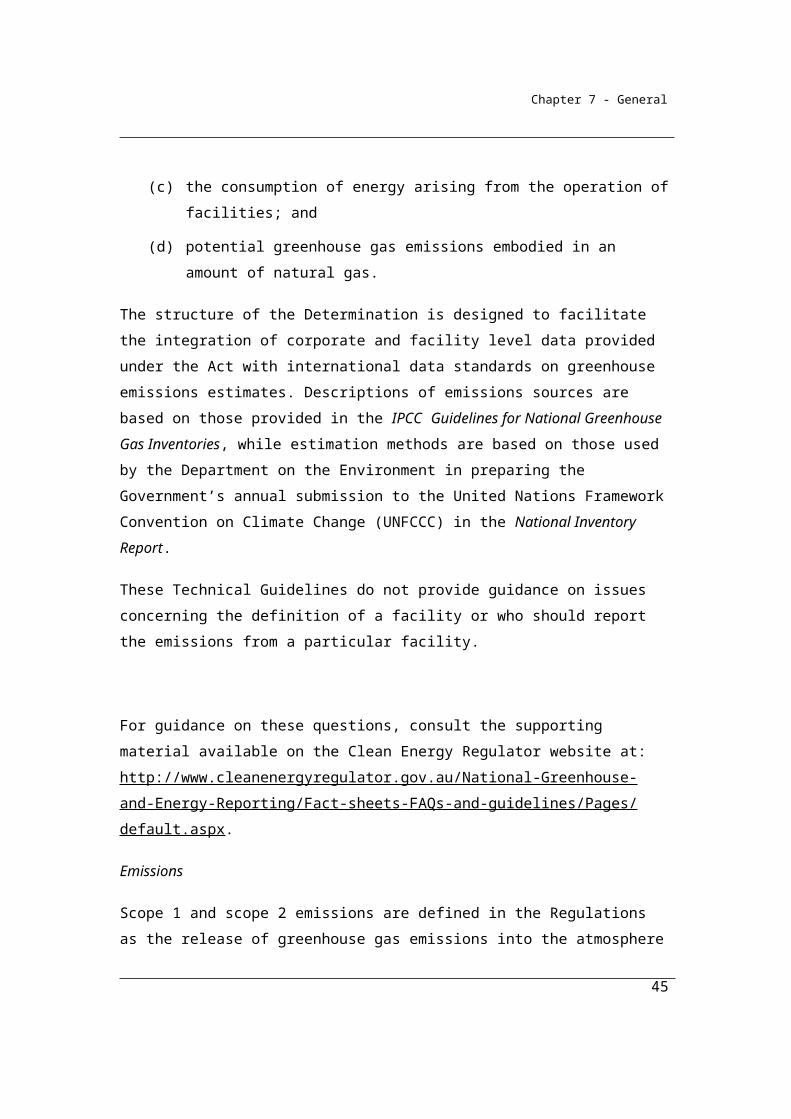
(a) greenhouse gas emissions arising from the operation of facilities;
(b) the production of energy arising from the operation of facilities;
(c) the consumption of energy arising from the operation of facilities; and
(d) potential greenhouse gas emissions embodied in an amount of natural gas.
The structure of the Determination is designed to facilitate the integration of corporate and facility level data provided under the Act with international data standards on greenhouse emissions estimates. Descriptions of emissions sources are based on those provided in the IPCC Guidelines for National Greenhouse Gas Inventories, while estimation methods are based on those used by the Department on the Environment in preparing the Government’s annual submission to the United Nations Framework Convention on Climate Change (UNFCCC) in the National Inventory Report.
These Technical Guidelines do not provide guidance on issues concerning the definition of a facility or who should report the emissions from a particular facility.
For guidance on these questions, consult the supporting material available on the Clean Energy Regulator website at:
33

Chapter 7 - General
http://www.cleanenergyregulator.gov.au/National-Greenhouse-and-Energy-Reporting/Fact-sheets-FAQs-and-guidelines/Pages/default.aspx.
Emissions
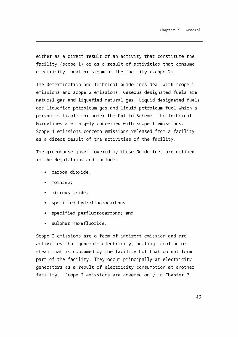
Scope 1 and scope 2 emissions are defined in the Regulations as the release of greenhouse gas emissions into the atmosphere either as a direct result of an activity that constitute the facility (scope 1) or as a result of activities that consume electricity, heat or steam at the facility (scope 2).
The Determination and Technical Guidelines deal with scope 1 emissions and scope 2 emissions. Gaseous designated fuels are natural gas and liquefied natural gas. Liquid designated fuels are liquefied petroleum gas and liquid petroleum fuel which a person is liable for under the Opt-In Scheme. The Technical Guidelines are largely concerned with scope 1 emissions. Scope 1 emissions concern emissions released from a facility as a direct result of the activities of the facility.
The greenhouse gases covered by these Guidelines are defined in the Regulations and include:
carbon dioxide;
methane;
nitrous oxide;
specified hydrofluorocarbons
specified perfluorocarbons; and
sulphur hexafluoride.
Scope 2 emissions are a form of indirect emission and are activities that generate electricity, heating, cooling or steam that is consumed by the facility but that do not form part of the facility. They occur principally at electricity generators as a result of electricity consumption at another facility. Scope 2 emissions are covered only in Chapter 7.
Natural gas is defined in the Regulations.
Coverage of Scope 1 emission sources in the Determination is given by the following categories:
34
Chapter 7 - General
(a) fuel combustion, which deals with emissions released from fuel combustion (see Chapter 2); and
(b) fugitive emissions from fuels, which deals with emissions mainly released from the extraction, production, processing and distribution of fossil fuels (Chapter 3); and
(c) industrial processes emissions, which deals with emissions released from the consumption of carbonates and the use of fuels as feedstocks or as carbon reductants, and the emission of synthetic gases in particular cases (see Chapter 4); and
(d) waste emissions, which deals with emissions mainly released from the decomposition of organic material in landfill or wastewater handling facilities (see Chapter 5).
The most important source is emissions from fuel combustion, which accounts for over 60 per cent of the emissions reported in the national greenhouse gas inventory.
The scope of the Determination does not include land based emissions covered by the UNFCCC categories ‘Agriculture’ and ‘Land Use, Land Use Change and Forestry’. However, emissions from fuel combustion or any other emission source listed above and which occurs from a facility operating within a land-based industry are, nonetheless, covered by the Determination.
Updates of these Guidelines
It is recognised that these Technical Guidelines will need to be updated as new information on emissions estimation methods becomes available. This will need to be balanced against the need to maintain time-series consistency of the emissions data as far as possible. Reflecting the need for this balance, it is planned that these Guidelines will be updated each year only for updated Scope 2 emission factors (see Chapter 7), while other revisions will occur on a periodic basis. It is planned that the Technical Guidelines will be updated periodically to:
provide Methods for emission sources where currently there are gaps or omissions in the Methods currently available;
35
Chapter 7 - General
take account of new documentary standards applicable to the estimation of emissions under Methods 2, 3 and 4;
take account of new information in relation to Method 1 emission factors; and
take account of new information in relation to the Methods detailed in the Determination.
The Department will continue to refine and elaborate the Determination as other issues arise from ongoing consultation, and domestic and international developments.
1.4 Overview—methods for measurement
Emissions are rarely measured through direct observation and are most often estimated by reference to readily observable variables that are closely related to greenhouse gas emissions such as the quantity of fossil fuels consumed.
These Guidelines provide Methods that allow for both direct emissions monitoring and the estimation of emissions through the tracking of observable, closely-related variables. This framework reflects the approaches of the international guidelines governing the estimation of national greenhouse gas inventories and, similarly, national practice such as for the EU Guidelines for the Monitoring and Reporting of Greenhouse Gas Emissions and the US EPA Mandatory Greenhouse Gas Reporting Rule.
At its simplest, emissions may be estimated by reference to reportable data such as fossil fuel consumption, evidenced by invoices, and the use of specified emission factors provided in these Guidelines. For emissions from fuel combustion, for example, data on consumption of a particular fuel would be multiplied by a specific emission factor for that fuel to generate an emissions estimate.
Greater levels of complexity and measurement effort may in some circumstances produce better estimates of emissions at facility level. This may result from, for example, sampling and analysis of a fuel consumed for its carbon content and other qualities that will affect actual emissions generated by its combustion at a facility. In Australia, this kind of approach to emissions estimation has been used for a number of years in the electricity industry.
36
Chapter 7 - General
Direct monitoring of emissions is also potentially an important approach to emissions estimation. While not common, such direct monitoring already occurs in some form in some instances such as in the coal industry, where state legislation requires the monitoring of methane levels for health and safety reasons.
Each of these broad approaches has been incorporated into the Guidelines as Methods for the estimation of emissions.
In particular four Methods have been described which provide a framework for emissions estimation for a range of purposes.
By drawing on existing emission estimation practices where possible, the Guidelines aim to allow reporters to meet their obligations efficiently. As indicated above, there are many instances where higher order methods (2, 3 and 4 set out below) already reflect current commercial or regulatory practice.
The provision for Reporters to select Methods for the estimation of emissions also allows Reporters to make their own judgements to balance the costs of using the higher-order methods with the benefits of potentially improved emission estimates.
A Framework for Method selection
For scope 1 emissions, the four Methods can be broadly described by the following:
Method 1: the National Greenhouse Accounts default method
Method 1 provides a class of estimation procedures derived directly from the methodologies used by the Department of the Environment and Energy for the preparation of the National Greenhouse Accounts. The use of methodologies from the National Greenhouse Accounts also anchors Method 1 within the international guidelines adopted by the UNFCCC for the estimation of greenhouse emissions.
Method 1 specifies the use of designated emission factors in the estimation of emissions. These emission factors are national average factors determined by the Department of the Environment and Energy using the Australian Greenhouse Emissions Information System (AGEIS).
Method 1 is likely to be most useful for emission sources where the source is relatively homogenous, such as from the combustion of standard liquid fossil fuels,
37
Chapter 7 - General
where the emissions resulting from combustion will be very similar across most facilities.
Estimates of emissions will be able to be calculated under Method 1 by Reporters using tools provided by the Department of the Environment and Energy.
Method 2: generally a facility-specific method using industry sampling and Australian or international standards listed in the Determination or equivalent for analysis of fuels and raw materials to provide more accurate estimates of emissions at facility level.
Method 2 enables corporations to undertake additional measurements - for example, the qualities of fuels consumed at a particular facility - in order to gain more accurate estimates for emissions for that particular facility.
Method 2 draws on the large body of Australian and international documentary standards prepared by standards organisations to provide the benchmarks for procedures for the analysis of, typically, the critical chemical properties of the fuels being combusted.
Method 2 is likely to be most useful for fuels which exhibit some variability in key qualities, such as carbon content, from source to source. This is the case for coal in Australia.
Method 2 is based on technical guidelines that were used by reporters under the Generator Efficiency Standards program. The possibility to report using this, higher order, approach is extended by the Determination from the electricity industry to all major consumers of fossil fuels.
Method 3: generally a facility-specific method using Australian or international standards listed in the Determination or equivalent standards for both sampling and analysis of fuels and raw materials
Method 3 is very similar to Method 2, except that it requires, additionally, Reporters to comply with Australian or international documentary standards for sampling (of fuels or raw materials) or equivalent as well as documentary standards for the analysis of fuels.
38
Chapter 7 - General
Method 4: direct monitoring of emission systems, either on a continuous or periodic basis.
Method 4 provides for a different approach to the estimation of emissions. Rather than analysing the chemical properties of inputs (or in some case, products), Method 4 provides approaches to enable direct monitoring of greenhouse gas emissions arising from an activity. This can provide a higher level of accuracy in certain circumstances, depending on the type of emission process although it is more data intensive than other approaches. Such direct monitoring already occurs, for example, in underground coal mines reflecting the nature of the emission process and the importance of relatively accurate data to support health and safety objectives.
As for Methods 2 and 3, there is a substantial body of documented procedures on monitoring practices and state and territory government regulatory experience that provide the principal sources of guidance for the establishment of such systems.
It is intended that the Reporter may select different methods for each source. For example, the Reporter may select different methods for different fuels and different methods for individual gases, subject to certain restrictions. In part, these differences reflect Method availability. For example, for solid fuels, only Method 1 has been provided for methane and nitrous oxide, reflecting the minor nature of the emission sources, whereas four methods are available for carbon dioxide.
1.5 Overview—energy
Methods for the estimation of the energy content of fuels produced and fuels consumed are addressed in Chapter 6. Data collected for the estimation of emissions from fuel combustion as set out in Chapter 2 will serve a dual purpose as the data for the consumption of energy. Separate collections are required, however, for the quantities of production of energy which, in general, do not enter directly into emission estimations.
1.6 Overview—scope 2 emissions
These Guidelines principally deal with Scope 1 emissions. These are direct emissions that arise on-site from the activities of a corporation. There are a wide
39
Chapter 7 - General
variety of emission sources that require a range of procedures to be described to cover the complexity of the emission pathways.
Scope 2 emissions arise principally at an electricity generator as a result of the purchase of electricity by a corporation. The method for the estimation of scope 2 emissions is given in Chapter 7. Scope 2 emission factors for the consumption of purchased electricity from Australia’s major electricity grids are be updated annually to reflect the latest data on the mix of electricity generation sources, which is a major determinant of the factors.
1.7 Overview—assessment of uncertainty
Chapter 8 deals with the assessment of statistical uncertainty for scope 1 emissions estimates. It is recognised that these calculations of uncertainty can be complex and relatively imprecise. A standardised approach to estimation of uncertainty of emissions estimates has been provided in Chapter 8.
Proposed changes to the NGER Regulations will only require reporters with emissions of more than 25 kilotonnes of CO2-e from the combustion of a fuel type, or a source other than fuel combustion to calculate and report the statistical uncertainty associated with their scope 1 emissions. Sources are defined in section 1.10 of the Measurement Determination and fuel types are set out in Schedule 1 of the NGER Regulations.
40
Chapter 7 - General
Division 1.1.2—Definitions and interpretationDefinitions of key terms used in these Guidelines are to be found at Appendix B. These definitions are drawn from both the Regulations and the Determination.
Many of the estimation methods reference documentary standards developed by, inter alia, standards organisations. Section 1.9 indicates that any standard, instrument or other writing must have been in force at 1 July 2012 to be applicable to an emissions estimation method. This means that any standard or similar instrument released after 1 July 2012 is not able to be referenced in a higher-order method. However, it is intended that the Determination will be reviewed at periodic intervals to consider recognition of such newly developed documentary standards.
1.9 Interpretation(1) In this Determination, a reference to emissions is a reference to emissions
of greenhouse gases.
(2) In this Determination, a reference to a gas type (j) is a reference to a greenhouse gas.
(3) In this Determination, a reference to a facility that is constituted by an activity is a reference to the facility being constituted in whole or in part by the activity.Note Section 9 of the Act defines a facility as an activity or series of activities.
(4) In this Determination, a reference to a standard, instrument or other writing (other than a Commonwealth Act or Regulations) however described, is a reference to that standard, instrument or other writing as in force on 1 July 2014.
1.9A Meaning of separate instance of a sourceIf 2 or more different activities of a facility have the same source of emissions, each activity is taken to be a separate instance of the source if the activity is performed by a class of equipment different from that used by another activity.
41

Chapter 7 - General
Example 1: The combustion of liquefied petroleum gas in the engines of distribution vehicles of the facility operator and the combustion of liquid petroleum fuel in lawn mowers at the facility, although the activities have the same source of emissions, are taken to be a separate instance of the source as the activities are different and the class of equipment used to perform the activities are different.
1.9B Meaning of separate occurrence of a source (1) If 2 or more things at a facility have the same source of emissions, each
thing may be treated as a separate occurrence of the source.
Example: The combustion of unprocessed natural gas in 2 or more gas flares at a facility may be treated as a separate occurrence of the source (natural gas production or processing—flaring).
(2) If a thing at a facility uses 2 or more energy types, each energy type may be treated as a separate occurrence of the source.
Example: The combustion of diesel and petrol in a vehicle at a facility may be treated as a separate occurrence of the source (fuel combustion).
1.10 Meaning of source
Sources of emissions are based on those provided in the IPCC Guidelines for National Greenhouse Gas Inventories and are defined in the Determination. The categories of source are listed in the table below and also correspond to a chapter heading in the Determination while the source of emissions in column 3 relate to the divisions within the chapters.
Item Category of source Source of emissions
1 Fuel combustion
1A Fuel combustion
2 Fugitive emissions
2A Underground mines
2B Open cut mines
2C Decommissioned underground mines
2D Oil or gas exploration
42

Chapter 7 - General
Item Category of source Source of emissions
2E Crude oil production
2F Crude oil transport
2G Crude oil refining
2H Natural gas production or processing (other than emissions that are vented or flared)
2I Natural gas transmission
2J Natural gas distribution
2K Natural gas production or processing – flaring
2L Natural gas production or processing – venting
2M Carbon capture and storage
3 Industrial processes
3A Cement clinker production
3B Lime production
3C Use of carbonates for the production of a product other than cement clinker, lime or soda ash
3D Soda ash use
3E Soda ash production
3F Ammonia production
3G Nitric acid production
3H Adipic acid production
3I Carbide production
3J Chemical or mineral production, other than carbide production, using a carbon reductant and carbon anode
3K Iron, steel or other metal production using an integrated metalworks
3L Ferroalloys production
3M Aluminium production
3N Other metals production
3O Emissions of hydrofluorocarbons and sulphur hexafluoride gases
43

Chapter 7 - General
Item Category of source Source of emissions
3P Sodium cyanide production
4 Waste
4A Solid waste disposal on land
4B Wastewater handling (industrial)
4C Wastewater handling (domestic or commercial)
4D Waste incineration
44
Chapter 7 - General
Part 1.2—General
1.11 Purpose of PartThis Part provides for general matters as follows:(a) Division 1.2.1 provides for the measurement of emissions and also
deals with standards;(b) Division 1.2.2 provides for methods for measuring emissions.
Division 1.2.1—Measurement and standards
1.12 Measurement of emissionsThe measurement of emissions released from the operation of a facility is to be done by estimating the emissions in accordance with this Determination.
1.13 General principles for measuring emissions
Estimates for this Determination must be prepared in accordance with the following principles:(a) transparency — emission estimates must be documented and
verifiable;(b) comparability — emission estimates using a particular method and
produced by a registered corporation or liable entity in an industry sector must be comparable with emission estimates produced by similar corporations or entities in that industry sector using the same method and consistent with the emission estimates published by the Department in the National Greenhouse Accounts;
(c) accuracy — having regard to the availability of reasonable resources by a registered corporation or liable entity and the requirements of this Determination, uncertainties in emission estimates must be minimised and any estimates must neither be over nor under estimates of the true values at a 95% confidence level;
(d) completeness — all identifiable emission sources mentioned in section 1.10 must be accounted for.
Time series consistency is also an important principle for measuring emissions. Chapter 5 of Volume 1 of the 2006 IPCC Guidelines for National Greenhouse Gas Inventories provides a detailed discussion of the issue. In short reporters should aim to estimate emissions in a time series consistently, which means that as far as
45
Chapter 7 - General
possible, the time series should be calculated using a consistent method and data sources over time. Restrictions on the method to be used for a source, provided in Division 1.2.2, and the criteria for measurement, provided in Part 1.3, and Divisions 2.2.5, 2.3.6, 2.4.6 and 4.2.5, have been put in place to promote time series consistency. These principles are derived from those that apply to the preparation of national inventories.
Note that there is a difference in meaning between the common usage of the word "confidence" and its statistical usage in relation to ‘95% confidence level’. For an explanation of ‘95% confidence level’ please refer to Chapter 8.
1.14 Assessment of uncertainty
The estimate of emissions released from the operation of a facility must include assessment of uncertainty in accordance with Chapter 8.
A standardised approach to estimation of uncertainty of emissions estimates has been provided in Chapter 8.
Proposed changes to the NGER Regulations will only require reporters with emissions of more than 25 kilotonnes of CO2-e from the combustion of a fuel type, or a source other than fuel combustion to calculate and report the statistical uncertainty associated with their scope 1 emissions. Sources are defined in section 1.10 of the Measurement Determination and fuel types are set out in Schedule 1 of the NGER Regulations.
1.15 Units of measurement
Standard units of measurement are prescribed for the standard reportable items.
Emissions of each greenhouse gas should be estimated and reported in tonnes of CO2-equivalent. Conversion factors from tonnes of emissions of each greenhouse gas to tonnes of emissions of carbon dioxide equivalent for that gas are called Global Warming Potentials and are listed in the Regulations and reproduced in Appendix C.
Emission estimation methods utilise standard units of measurement for solid, gaseous and liquid fuels, unless otherwise specified. For gaseous fuels, the
46

Chapter 7 - General
standard unit of measurement is cubic metres, although allowance is made for measurement in gigajoules if data is available in those units.
The standard units for fuels should also be used for reporting. For example, solid fuels should be reported in tonnes.
(1) For this Determination, measurements of fuel must be converted as follows:(a) for solid fuel, to tonnes; and(b) for liquid fuels, to kilolitres unless otherwise specified; and(c) for gaseous fuels, to cubic metres, corrected to standard conditions,
unless otherwise specified.
(2) For this Determination, emissions of greenhouses gases must be estimated in CO2-e tonnes.
(3) Measurements of energy content must be converted to gigajoules.
(4) The National Measurement Act 1960, and any instrument made under that Act, must be used for conversions required under this section.
1.16 Rounding of amounts
(1) If:(a) an amount is worked out under this Determination; and(b) the number is not a whole number;then:(c) the number is to be rounded up to the next whole number if the number
at the first decimal place equals or exceeds 5; and(d) rounded down to the next whole number if the number at the first
decimal place is less than 5.
(2) Subsection (1) applies to amounts that are measures of emissions or energy.
1.17 Status of standards
If there is an inconsistency between this Determination and a documentary standard, this Determination prevails to the extent of the inconsistency.
47
Chapter 7 - General
Division 1.2.2—Methods
1.18 Method to be used for a separate occurrence of a source
(1) This section deals with the number of methods that may be used to estimate emissions of a particular greenhouse gas released, in relation to a separate occurrence of a source, from the operation of a facility.
(1A) Subsections (2) and (3) do not apply to a facility if:(a) the principal activity of the facility is electricity generation (ANZSIC
industry classification and code 2611) and the generating unit used to perform the principal activity:(i) does not have the capacity to generate, in a reporting year, the
amount of electricity mentioned in subparagraph 2.3(3)(b)(i); and
(ii) generates, in a reporting year, less than or equal to the amount of electricity mentioned in subparagraph 2.3(3)(b)(ii); or
(b) the principal activity of the facility is electricity generation (ANZSIC industry classification and code 2611) and the generating unit used to perform the principal activity:(i) does not have the capacity to generate, in a reporting year, the
amount of electricity mentioned in subparagraph 2.19(3)(b)(i); and
(ii) generates, in a reporting year, less than or equal to the amount of electricity mentioned in subparagraph 2.19(3)(b)(ii).
(2) Subject to subsection (3) and (3A), one method for the separate occurrence of a source must be used for 4 reporting years unless another higher method is used.
(3) If:(a) at a particular time, a method is being used to estimate emissions in
relation to the separate occurrence of a source; and(b) either:
(i) in the preceding 4 reporting years before that time, only that method has been used to estimate the emissions from the separate occurrence of the source; or
(ii) a registered corporation or liable entity certifies in writing that the method used was found to be non-compliant during an external audit of the separate occurrence of the source;
48
Chapter 7 - General
then a lower method may be used to estimate emissions in relation to the separate occurrence of the source from that time.
(3A) If section 22AA of the Act applies to a person, a lower method may be used to estimate emissions in relation to the source for the purposes of reporting under section 22AA.
(4) In this section, reporting year, in relation to a source from the operation of a facility under the operational control of a registered corporation and entities that are members of the corporation’s group, means a year that the registered corporation is required to provide a report under section 19 of the Act in relation to the facility
(5) Higher method, is:(a) a prescribed alternative method; or(b) in relation to a method (the original method) being used to estimate
emissions in relation to a separate occurrence of a source, a method for the source with a higher number than the number of the original method.
(6) Lower method, is:(a) a default method; or(b) in relation to a method (the original method) being used to estimate
emissions in relation to a separate occurrence of a source, a method for the source with a lower number than the number of the original method.
1.18A Conditions—persons preparing report must use same method
(1) This section applies if a person is required, under section 19, 22A, 22AA, 22E, 22G or 22X of the Act (a reporting provision), to provide a report to the Regulator for a reporting year or part of a reporting year (the reporting period).
(2) For paragraph 10(3)(c) of the Act:(a) the person must, before 31 August in the year immediately following
the reporting year, notify any other person required, under a reporting provision, to provide a report to the Regulator for the same facility of the method the person will use in the report; and
(b) each person required to provide a report to the Regulator for the same facility and for the same reporting period must, before 31 October in the year immediately following the reporting year, take all reasonable steps to agree on a method to be used for each
49
Chapter 7 - General
report provided to the Regulator for the facility and for the reporting period.
(3) If the persons mentioned in paragraph (2)(b) do not agree on a method before 31 October in the year immediately following the reporting year, each report provided to the Regulator for the facility and for the reporting period must use the method:
(a) that was used in a report provided to the Regulator for the facility for the previous reporting year (if any); and
(b) that will, of all the methods used in a report provided to the Regulator for the facility for the previous reporting year, result in a measurement of the largest amount of emissions for the facility for the reporting year.
(4) In this section, a reference to a method is a reference to a method or available alternative method, including the options (if any) included in the method or available alternative method.Note 1: Reporting year has the meaning given by the Regulations.
Note 2: An example of available alternative methods is method 2 in section 2.5 and method 2 in section 2.6.
Note 3: An example of options included within a method is paragraphs 3.36(a) and (b), which provide 2 options of ways to measure the size of mine void volume.
Note 4: An example of options included within an available alternative method is the options for identifying the value of the oxidation factor (OFs) in subsection 2.5(3).
1.19 Temporary unavailability of method
(1) The procedure set out in this section applies if, during a reporting year, a method for a separate occurrence of a source or potential greenhouse gas emissions embodied in an amount of designated fuel cannot be used because of a mechanical or technical failure of equipment or a failure of measurement systems during a period (the down time).
(2) For each day or part of a day during the down time, the estimation of emissions from the separate occurrence of a source or potential greenhouse gas emissions embodied in an amount of designated fuel must be consistent with the principles in section 1.13.
(3) Subsection (2) only applies for a maximum of 6 weeks in a year. This period does not include down time taken for the calibration of the equipment.
50
Chapter 7 - General
(4) If down time is more than 6 weeks in a year, the registered corporation or liable entity must inform the Regulator, in writing, of the following:
(a) the reason why down time is more than 6 weeks;(b) how the corporation or entity plans to minimise down time;(c) how emissions have been estimated during the down time.
(5) The information mentioned in subsection (4) must be given to the Regulator within 6 weeks after the day when down time exceeds 6 weeks in a year.
(6) The Regulator may require a registered corporation or liable entity to use method 1 to estimate emissions during the down time if:
(a) method 2, 3 or 4 has been used to estimate emissions for the separate occurrence of a source; and
(b) down time is more than 6 weeks in a year.
Division 1.2.3 Requirements in relation to carbon capture and storage
The National Greenhouse and Energy Reporting Regulations currently require facilities involved in carbon capture and storage to report fugitive emissions from transport, injection and the storage site as well as the stock of carbon dioxide stored and the amount of carbon dioxide captured, imported and injected (see Regulation 4.12).
This division sets out methods to support the requirements of the regulations for carbon capture and storage.
This division defines the meaning of ‘captured for permanent storage’ and the requirements allowing facilities that capture carbon dioxide for permanent storage in an underground geological formation to deduct that amount of carbon dioxide in the emissions estimation process for that facility. The storage must be permanent and is defined as such only if the carbon dioxide is transferred to an underground geological formation that is regulated under national or State legislation.
Other requirements for carbon capture and storage (CCS) define how the deductions are to be attributed where there are multiple sources or fuels consumed and the measurement criteria to be applied for the carbon dioxide captured.
51
Chapter 7 - General
Methods to estimate fugitive emissions from transport of the carbon dioxide for permanent storage can be found in Part 3.4.
The scope of the amendments for CCS reflects the status of the regulatory framework as well as the technology available for permanent storage of carbon dioxide. The CCS regulatory framework is under development and is not yet comprehensive.
The provisions for CCS should be considered to be a first step in the process of the development of a comprehensive provision for the treatment of carbon capture and storage in the NGER system.
1.19A Meaning of captured for permanent storage
For this Determination, carbon dioxide is captured for permanent storage only if it is captured by, or transferred to:
(a) the registered holder of a greenhouse gas injection licence under the Offshore Petroleum and Greenhouse Gas Storage Act 2006 for the purpose of being injected into an identified greenhouse gas storage formation under the licence in accordance with that Act; or
(b) the holder of an injection and monitoring licence under the Greenhouse Gas Geological Sequestration Act 2008 (Vic) for the purpose of being injected into an underground geological formation under the licence in accordance with that Act; or
(c) the registered holder of a greenhouse gas injection licence under the Offshore Petroleum and Greenhouse Gas Storage Act 2010 (Vic) for the purpose of being injected into an identified greenhouse gas storage formation under the licence in accordance with that Act; or
(d) the holder of a GHG injection and storage lease under the Greenhouse Gas Storage Act 2009 (Qld) for the purpose of being injected into a GHG stream storage site under the lease in accordance with that Act; or
(e) the holder of an approval under the Barrow Island Act 2003 (WA) for the purpose of being injected into an underground reservoir or other subsurface formation in accordance with that Act; or
(f) the holder of a gas storage licence under the Petroleum and Geothermal Energy Act 2000 (SA) for the purpose of being injected into a natural reservoir under the licence in accordance with that Act.
52
Chapter 7 - General
1.19B Deducting carbon dioxide that is captured for permanent storage
The amount of carbon dioxide captured for permanent storage may be deducted from the emissions estimate for the relevant source. Where method 4 is used to measure emissions from a facility a deduction for carbon dioxide captured for permanent storage is not required since emissions are measured directly under this method and do not include the carbon dioxide captured for permanent storage.
In determining the amount of carbon dioxide that is captured for permanent storage it is considered good practice to measure the volume of the carbon dioxide stream and the concentration of carbon dioxide in the stream at the point of capture.
(1) If a provision of this Determination provides that an amount of carbon dioxide that is captured for permanent storage may be deducted in the estimation of emissions under the provision, then the amount of carbon dioxide may be deducted only if:
(a) the carbon dioxide that is captured for permanent storage is captured by, or transferred to, a relevant person; and
(b) the amount of carbon dioxide that is captured for permanent storage is estimated in accordance with section 1.19E; and
(c) the relevant person issues a written certificate that complies with subsection (2).
(2) The certificate must specify:(a) if the carbon dioxide is captured by the relevant person and is neither
transferred to the relevant person nor transferred by the relevant person to another person—the following information:(i) the amount of carbon dioxide captured by the relevant person;
(ii) the volume of the carbon dioxide stream containing the captured carbon dioxide;
(iii) the concentration of carbon dioxide in the stream; or(b) if the carbon dioxide is transferred to the relevant person—the
following information:(i) the amount of carbon dioxide that was transferred to the relevant
person;(ii) the volume of the carbon dioxide stream containing the
transferred carbon dioxide;(iii) the concentration of carbon dioxide in the stream.
53
Chapter 7 - General
(3) The amount of carbon dioxide that may be deducted is the amount specified in the certificate under paragraph (1)(c).
1.19C Capture from facility with multiple sources jointly generated
If, during the operation of a facility, more than 1 source generates carbon dioxide, the total amount of carbon dioxide that may be deducted in relation to the facility is to be attributed:
(a) if it is possible to determine the amount of carbon dioxide that is captured for permanent storage from each source—to each source from which the carbon dioxide is captured according to the amount captured from the source; or
(b) if it is not possible to determine the amount of carbon dioxide captured for permanent storage from each source—to the main source that generated the carbon dioxide that is captured during the operation of the facility.
1.19D Capture from a source where multiple fuels consumed
If more than 1 fuel is consumed for a source that generates carbon dioxide that is captured for permanent storage, the total amount of carbon dioxide that may be deducted in relation to the source is to be attributed to each fuel consumed in proportion to the carbon content of the fuel relative to the total carbon content of all fuel consumed for that source.
1.19E Measure of quantity of carbon dioxide captured
(1) For paragraph 1.19B(1)(b), the amount of captured carbon dioxide must be estimated in accordance with this section.
(2) The volume of the carbon dioxide stream containing the captured carbon dioxide must be estimated:
(a) if the carbon dioxide stream is transferred to a relevant person—using:(i) criterion A in section 1.19F; or
(ii) criterion AAA in section 1.19G; or(b) if the carbon dioxide stream is captured by the relevant person and is
neither transferred to the relevant person nor transferred by the relevant person to another person—using:(i) criterion AAA in section 1.19G; or
(ii) criterion BBB in section 1.19N.
54
Chapter 7 - General
(3) The carbon dioxide stream must be sampled in accordance with ISO 10715:1997, or an equivalent standard.
(4) The concentration of carbon dioxide in the carbon dioxide stream must be analysed in accordance with the following parts of ISO 6974 or an equivalent standard:
(a) Part 1 (2000);(b) Part 2 (2001);(c) Part 3 (2000);(d) Part 4 (2000);(e) Part 5 (2000);(f) Part 6 (2002).
(5) The volume of the carbon dioxide stream must be expressed in cubic metres.
(6) The carbon dioxide stream must be analysed for concentration of carbon dioxide on at least a monthly basis.
1.19F Volume of carbon dioxide stream—criterion A
(1) For subparagraph 1.19E(2)(a)(i), criterion A is the volume of the carbon dioxide stream that is:
(a) transferred to the relevant person during the year; and(b) specified in a certificate issued by the relevant person under
paragraph 1.19B(1)(c).
(2) The volume specified in the certificate must be accurate and must be evidenced by invoices issued by the relevant person.
1.19G Volume of carbon dioxide stream—criterion AAA
(1) For subparagraphs 1.19E(2)(a)(ii) and (b)(i), criterion AAA is the measurement during the year of the captured carbon dioxide stream from the operation of a facility at the point of capture.
(2) In measuring the quantity of the carbon dioxide stream at the point of capture, the quantity of the carbon dioxide stream must be measured:
(a) using volumetric measurement in accordance with:(i) for a carbon dioxide stream that is not super-compressed—
section 1.19H; and(ii) for a super-compressed carbon dioxide stream—section 1.19I;
and
55
Chapter 7 - General
(b) using gas measuring equipment that complies with section 1.19J.
(3) The measurement must be carried out using measuring equipment that:(a) is in a category specified in column 2 of an item in the table in
subsection (4) according to the maximum daily quantity of the carbon dioxide stream captured specified in column 3 for that item from the operation of the facility; and
(b) complies with the transmitter and accuracy requirements for that equipment specified in column 4 for that item, if the requirements are applicable to the measuring equipment being used.
(4) For subsection (3), the table is as follows.
Item
Gas measuring equipment category
Maximum daily quantity of carbon dioxide stream cubic metres/day
Transmitter and accuracy requirements (% of range)
1 1 0–50 000 Pressure <±0.25%Diff. pressure <±0.25%Temperature <±0.50%
2 2 50 001–100 000 Pressure <±0.25%Diff. pressure <±0.25%Temperature <±0.50%
3 3 100 001–500 000 Smart transmitters:Pressure <±0.10%Diff. pressure <±0.10%Temperature <±0.25%
4 4 500 001 or more Smart transmitters:Pressure <±0.10%Diff. pressure <±0.10%Temperature <±0.25%
1.19H Volumetric measurement—carbon dioxide stream not super-compressed
(1) For subparagraph 1.19G(2)(a)(i), volumetric measurement of a carbon dioxide stream that is not super-compressed must be in cubic metres at standard conditions.
(2) The volumetric measurement is to be calculated using a flow computer that measures and analyses flow signals and relative density:
56
Chapter 7 - General
(a) if the carbon dioxide stream is captured by the relevant person and is neither transferred to the relevant person nor transferred by the relevant person to another person—at the point of capture of the carbon dioxide stream; or
(b) if the carbon dioxide stream is transferred to a relevant person—at the point of transfer of the carbon dioxide stream.
(3) The volumetric flow rate must be continuously recorded and integrated using an integration device that is isolated from the flow computer in such a way that if the computer fails, the integration device will retain the last reading, or the previously stored information, that was on the computer immediately before the failure.
(4) Subject to subsection (5), all measurements, calculations and procedures used in determining volume (except for any correction for deviation from the ideal gas law) must be made in accordance with the instructions contained in the following:
(a) for orifice plate measuring systems:(i) the publication entitled AGA Report No. 3, Orifice Metering of
Natural Gas and Other Related Hydrocarbon Fluids Part 3: Natural Gas Applications, published by the American Gas Association in August 1992; or
(ii) Parts 1 to 4 of the publication entitled ANSI/API MPMS Chapter 14.3 Part 2 (R2011) Natural Gas Fluids Measurement: Concentric, Square-Edged Orifice Meters - Part 2: Specification and Installation Requirements, 4th edition, published by the American Petroleum Institute on 30 April 2000;
(b) for turbine measuring systems—the publication entitled AGA Report No. 7, Measurement of Natural Gas by Turbine Meter (2006), published by the American Gas Association on 1 January 2006;
(c) for positive displacement measuring systems—the publication entitled ANSI B109.3—2000, Rotary Type Gas Displacement Meters, published by the American Gas Association on 13 April 2000.
(5) Measurements, calculations and procedures used in determining volume may also be made in accordance with an equivalent internationally recognised documentary standard or code.
(6) Measurements must comply with Australian legal units of measurement.
57
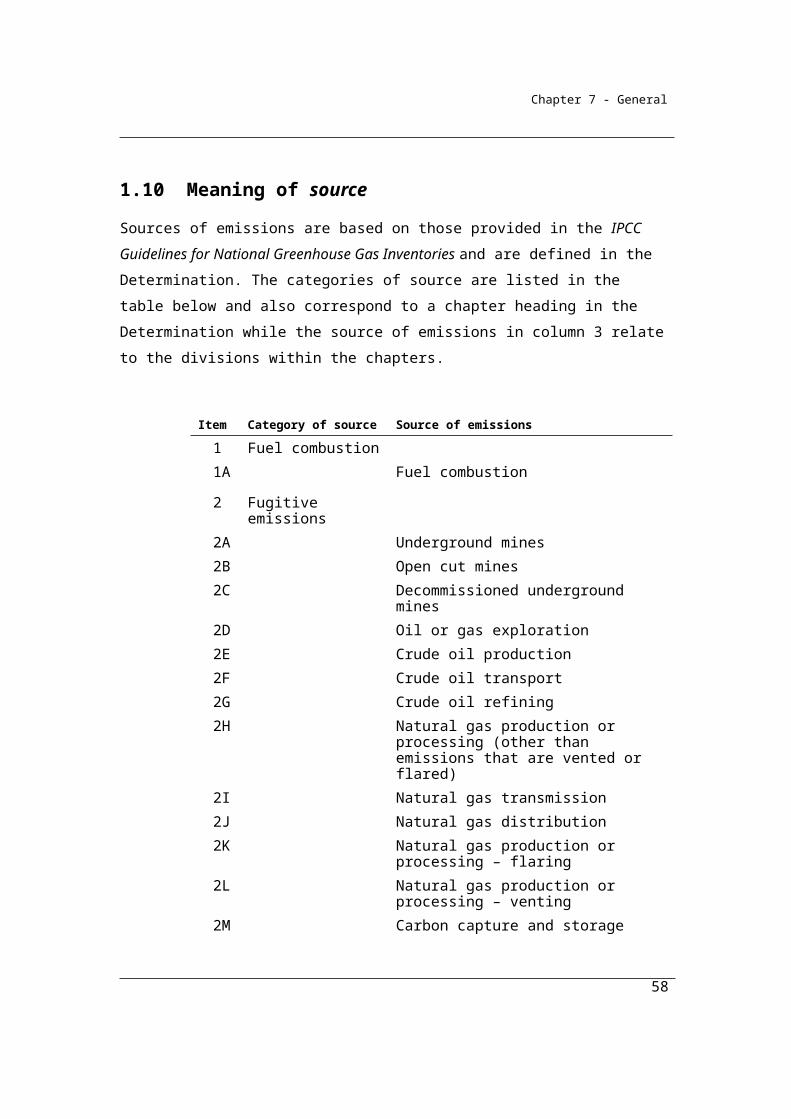
Chapter 7 - General
1.19I Volumetric measurement—super-compressed carbon dioxide stream
(1) For subparagraph 1.19G(2)(a)(ii), volumetric measurement of a super-compressed carbon dioxide stream must be in accordance with this section.
(2) If, in determining volume in relation to the super-compressed carbon dioxide stream, it is necessary to correct for deviation from the ideal gas law, the correction must be determined using the relevant method contained in the publication entitled American Gas Association Transmission Measurement Committee Report No. 8 (1992) Super-compressibility published by the American Gas Association.
(3) The measuring equipment used must calculate super-compressibility by:(a) if the measuring equipment is category 3 or 4 equipment in
accordance with column 2 the table in subsection 1.19G(4)—using composition data; or
(b) if the measuring equipment is category 1 or 2 equipment in accordance with column 2 of the table in subsection 1.19G(4)—using an alternative method set out in the publication entitled American Gas Association Transmission Measurement Committee Report No. 8 (1992) Super-compressibility published by the American Gas Association.
1.19J Gas measuring equipment—requirements
For paragraph 1.19G(2)(b), gas measuring equipment that is category 3 or 4 equipment in accordance with column 2 of the table in subsection 1.19G(4) must comply with the following requirements:
(a) if the equipment uses flow devices—the requirements relating to flow devices set out in section 1.19K;
(b) if the equipment uses flow computers—the requirement relating to flow computers set out in section 1.19L;
(c) if the equipment uses gas chromatographs—the requirements relating to gas chromatographs set out in section 1.19M.
1.19K Flow devices—requirements
(1) If the measuring equipment has flow devices that use orifice measuring systems, the flow devices must be constructed in a manner that ensures that the maximum uncertainty of the discharge coefficient is not greater than ±1.5%.
58
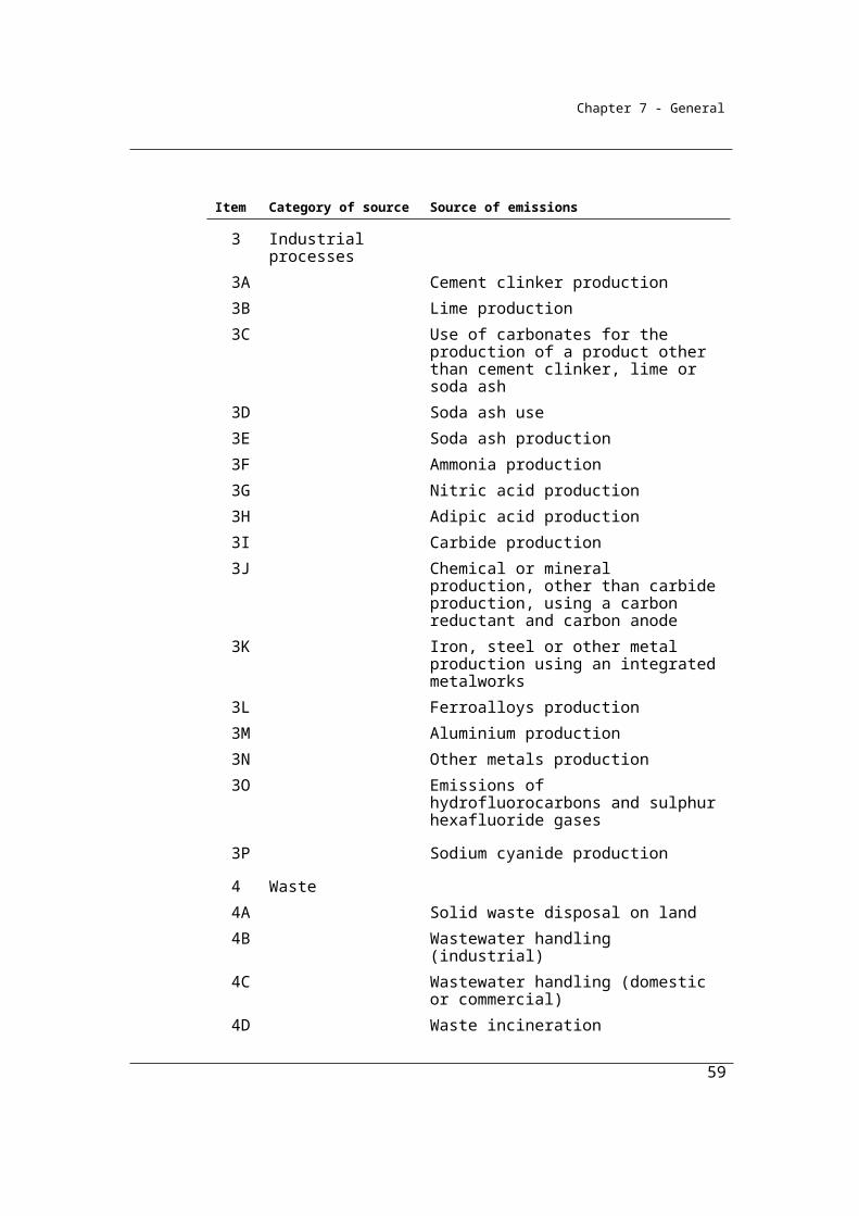
Chapter 7 - General
Note: The publication entitled AGA Report No. 3, Orifice Metering of Natural Gas and Other Related Hydrocarbon Fluids Part 3: Natural Gas Applications, published by the American Gas Association in August 1992, sets out a manner that ensures that the maximum uncertainty of the discharge coefficient is not greater than ±1.5%.
(2) If the measuring equipment has flow devices that use turbine measuring systems, the flow devices must be installed in a manner that ensures that the maximum uncertainty of the flow measurement is not greater than ±1.5%.Note: The publication entitled American Gas Association Transmission
Measurement Committee Report No. 8 (1992) Super-compressibility, published by the American Gas Association, sets out a manner that ensures that the maximum uncertainty of the flow measurement is not greater than ±1.5%.
(3) If the measuring equipment has flow devices that use positive displacement measuring systems, the flow devices must be installed in a manner that ensures that the maximum uncertainty of flow is ±1.5%.Note: The publication entitled ANSI B109.3—2000, Rotary Type Gas Displacement
Meters, published by the American Gas Association on 13 April 2000, sets out a manner for installation that ensures that the maximum uncertainty of flow is ±1.5%.
(4) If the measuring equipment uses any other type of flow device, the maximum uncertainty of flow measurement must not be greater than ±1.5%.
(5) All flow devices that are used by measuring equipment of a category specified in column 2 of the table in subsection 1.19G(4) must, wherever possible, be calibrated for pressure, differential pressure and temperature in accordance with the requirements specified in column 4 for the category of equipment specified in column 2 for that item. The calibrations must take into account the effects of static pressure and ambient temperature.
1.19L Flow computers—requirements
For paragraph 1.19J(b), the requirement is that the flow computer that is used by the equipment for measuring purposes must record the instantaneous values for all primary measurement inputs and must also record the following outputs:
(a) instantaneous corrected volumetric flow;(b) cumulative corrected volumetric flow;
59
Chapter 7 - General
(c) for turbine and positive displacement metering systems—instantaneous uncorrected volumetric flow;
(d) for turbine and positive displacement metering systems—cumulative uncorrected volumetric flow;
(e) super-compressibility factor.
1.19M Gas chromatographs
For paragraph 1.19J(c), the requirements are that gas chromatographs used by the measuring equipment must:
(a) be factory tested and calibrated using a measurement standard produced by gravimetric methods and traceable to Australian units of measurement required by or under the National Measurement Act 1960; and
(b) perform gas composition analysis with an accuracy of ±0.25% for calculation of relative density; and
(c) include a mechanism for re-calibration against a certified reference gas.
1.19N Volume of carbon dioxide stream—criterion BBB
For subparagraph 1.19E(2)(b)(ii), criterion BBB is the estimation of the volume of the captured carbon dioxide stream from the operation of the facility during a year measured in accordance with industry practice if the equipment used to measure the volume of the captured carbon dioxide stream does not meet the requirements of criterion AAA.Note: An estimate obtained using industry practice must be consistent with the
principles in section 1.13.
60
Chapter 7 - General
Part 1.3—Method 4—Direct measurement of emissions
Division 1.3.1—Preliminary
1.20 Overview
Method 4 provides for direct measurement of emissions of greenhouse gases. Such measurement systems can be established, for example, in flues, stacks, pipes or ducts and may be applicable in a number of industries, although not all.
Method 4 establishes a framework for the design, installation, performance and maintenance of direct emissions measurement systems for stationary emission sources and a guide to measurement, recording, and standardised reporting for estimating greenhouse gas emissions.
Two systems for direct emissions monitoring are available including:
(a) Continuous emissions monitoring (CEM);
(b) Periodic emissions monitoring (PEM).
The use of Method 4 by corporations will likely depend on a number of factors including the type of emissions process, the structures of the facility and any current direct measurement systems that corporations may have in place for measuring pollutants for other purposes.
The general framework for Method 4 draws on the following publications:
U.S. Environmental Protection Agency. 2003. Code of Federal Regulations: Standards of Performance for New Stationary Sources. Appendix A – Test Methods. 40 CFR 60 Appendix A. Washington, D.C. These methods can be obtained from: http://www.epa.gov/ttn/emc/promgate.html
The Commission of the European Communities, Commission Decision establishing guidelines for the monitoring and reporting of greenhouse gas
61

Chapter 7 - General
emissions pursuant to Directive 2003/87/EC of the European Parliament and of the Council. Brussels, 2006. This document can be obtained from: http://ec.europa.eu/index_en.htm
The Environmental Protection Agency, Load Calculation Protocol for use by holders of NSW environment protection licenses when calculating assessable pollutant loads. Department of Environment and Conservation (NSW), February 2005. This document can be obtained from: http://www.environment.nsw.gov.au/licensing/lblprotocol/
Department of Environment and Heritage, National Pollutant Inventory – Emission Estimation Manual for Fossil Fuel Electric Power Generation, Version 2.4, March 2005. This document can be obtained from: http://www.npi.gov.au/
West Australian Department of Environment and Conservation, Department of Environment and Conservation Continuous Emissions Monitoring System (CEMS) Code for Stationary Source Air Emissions, October 2006. This document can be obtained from http://www.dec.wa.gov.au/
(1) This Chapter provides for method 4 for a source.Note: Method 4 as provided for in this Part applies to a source as indicated in the
Chapter, Part, Division or Subdivision dealing with the source.
(2) Method 4 requires the direct measurement of emissions released from the source from the operation of a facility during a year by monitoring the gas stream at a site within part of the area (for example, a duct or stack) occupied for the operation of the facility.
(3) Method 4 consists of the following:(a) method 4 (CEM) as specified in section 1.21 that requires the
measurement of emissions using continuous emissions monitoring (CEM);
(b) method 4 (PEM) as specified in section 1.27 that requires the measurement of emissions using periodic emissions monitoring (PEM).
62

Chapter 7 - General
Division 1.3.2—Operation of method 4 (CEM)Continuous Emissions Monitoring (CEM) systems are designed to monitor real-time occurrence of emissions. The aim of the CEM method is to provide the framework for calculating emissions and also to provide standards for the location of sampling positions, measurement of flow rates and gas concentrations and the frequency of measurements.
Subdivision 1.3.2.1—Method 4 (CEM)
1.21 Method 4 (CEM)—estimation of emissions
CEM systems may record emissions automatically via a computer or it may be necessary for emissions to be calculated manually. The equation in 1.21 (1) provides a method to be used to calculate emissions manually from direct emissions monitoring under CEM systems. The equation uses the data gathered from flow rate and gas analyser equipment to calculate mass emissions.
In order to convert volumetric flow rates to mass flow rates accurately, direct measurement also requires the measurement of temperature and pressure to reduce the amount of error that is associated with the variability of density factors used to convert from volume of a gas to the mass of a gas. The equation in 1.21 (1) is cited from the report:
Mark, M., Worrall, R., Mallett, C., and Xue, S. (2001). Measuring and Reporting Greenhouse Gas Emissions. ACARP Project C8061. CSIRO Exploration and Mining Report 805C.
This report can be obtained from: http://www.acarp.com.au/reports.aspx.
(1)To obtain an estimate of the mass of emissions of a gas type (j), being methane, carbon dioxide or nitrous oxide, released at the time of measurement at a monitoring site within the area occupied for the operation of a facility, the following formula must be applied:
j ct ct jctjct
ct
MM ×P ×FR ×CM =
8.314T
where:
63

Chapter 7 - General
Mjct is the mass of emissions in tonnes of gas type (j) released per second.
MMj is the molecular mass of gas type (j) measured in tonnes per kilomole which:
(a) for methane is 16.0410-3; or(b) for carbon dioxide is 44.0110-3; or(c) for nitrous oxide is 44.0110-3.
Pct is the pressure of the gas stream in kilopascals at the time of measurement.
FRct is the flow rate of the gas stream in cubic metres per second at the time of measurement.
Cjct is the proportion of gas type (j) in the volume of the gas stream at the time of measurement.
Tct is the temperature, in degrees kelvin, of the gas at the time of measurement.
(2) The mass of emissions estimated under subsection (1) must be converted into CO2-e tonnes.
(3) Data on estimates of the mass emissions rates obtained under subsection (1) during an hour must be converted into a representative and unbiased estimate of mass emissions for that hour.
(4) The estimate of emissions of gas type (j) during a year is the sum of the estimates for each hour of the year worked out under subsection (3).
(5) If method 1 is available for the source, the total mass of emissions for a gas from the source for the year calculated under this section must be reconciled against an estimate for that gas from the facility for the same period calculated using method 1 for that source.
64

Chapter 7 - General
Example: Continuous emissions monitoring of CH4 from fugitive emissions associated with underground coal mining.
Step 1. Calculate the emission rate for each measurement period using the equation in section 1.21.
Measurement
(time)
MMct (CO2
tonnes per
kilomole)
Pct (kPa) FRct
(M3/sec)
Cjct
(v/v)
Gas
constant
Tct
(degrees
Kelvin)
Emission
rate
(CH4
tonnes per
sec)
Emission
rate
(CO2-e
tonnes per
sec)
a b c d e f g H
1.00PM 0.01604 101.300 300 0.009 8.314 295.0 1.79E-03 4.47E-02
1.15PM 0.01604 101.320 310 0.012 8.314 295.5 2.46E-03 6.15E-02
1.30PM 0.01604 101.315 307 0.011 8.314 295.4 2.23E-03 5.59E-02
1.45PM 0.01604 101.315 305 0.010 8.314 295.1 2.02E-03 5.05E-02
2.00PM 0.01604 101.310 303 0.010 8.314 295.2 2.01E-03 5.02E-02
2.15PM 0.01604 101.315 304 0.011 8.314 295.3 2.21E-03 5.53E-02
2.30PM 0.01604 101.320 308 0.011 8.314 295.3 2.24E-03 5.61E-02
2.45PM 0.01604 101.320 311 0.012 8.314 295.4 2.47E-03 6.17E-02
Step 2. Calculate the average emissions rate for an hour by summing the emission estimates in column h of the table and divide by the number of sample periods for the hour:
Average emission rate for the first hour (1.00PM to 2.00PM)
= (4.47E-02+6.15E-02+5.59E-02+5.05E-02)/4
= 5.32E-02 CO2-e tonnes per second
Average emission rate for the second hour (2.00PM to 3.00PM)
= = (5.02E-02+5.53E-02+5.61E-02+6.17E-02)/4
= 4.69E-02 CO2-e tonnes per second
Step 3. The mass emissions for the hour is then calculated by multiplying the average emission rate for the hour in step 1 by the number of seconds in an hour, which is 3600.
Therefore:
65
Chapter 7 - General
Emissions for the first hour = 4.46E-02 x 3600
Emissions for the first hour = 5.32E-02 x 3600
191.3 tonnes CO2-e for the hour
Emissions for the second hour = 5.58E-02 x 3600
201.0 tonnes CO2-e for the hour
To aggregate emissions for a period, the hourly emissions estimates are summed together. For example, total emissions between 1.00 and 3.00pm in the above example is calculated by adding together 191.3 and 201.0 tonnes of CO2-e which equals 392.3 tonnes of CO2-e.
1.21A Emissions from a source where multiple fuels consumed
If more than one fuel is consumed for a source that generates carbon dioxide that is directly measured using method 4 (CEM), the total amount of carbon dioxide is to be attributed to each fuel consumed in proportion to the carbon content of the fuel relative to the total carbon content of all fuel consumed for that source.
Example: Attributing CO2 emissions from fuel combustion measured using method 4 where diesel oil and natural gas is consumed
A facility combusts 5,000 kilolitres of diesel oil and 1,800,000 GJ of natural gas in a gas turbine during the
reporting year.
The facility elects to use continuous emissions monitoring (CEM) under Method 4 to estimate emissions of
carbon dioxide. The reporter estimates a total of 104,852 tonnes CO2 from this source using continuous
emissions monitoring (CEM) during the year.
In order to attribute these emissions to each fuel the carbon content of the two fuels are estimated using the
default carbon content factors published in Schedule 3 of the NGER (Measurement) Determination.
CO2 emissions attributed to fuel x = total CEM emission estimate * carbon content of fuel x/ carbon content of
all fuels
Carbon content of diesel oil = 5,000 kL * 0.736 t C/kL = 3,680 t C
Carbon content of natural gas = 1,800,000 GJ * 0.014 t C/GJ = 25,200 t C
CO2 emissions attributed to diesel oil = total CEM emission estimate * carbon content of diesel oil/ (carbon
66
Chapter 7 - General
content of diesel oil+ carbon content of natural gas)
Emissions attributed to diesel oil = 104852 t CO2 * 3,680 t C/ 28,880 t C = 13,361 t CO2
Emissions attributed to natural gas = total CEM emission estimate * carbon content of natural gas/ (carbon
content of diesel oil+ carbon content of natural gas)
Emissions attributed to natural gas = 104852 t CO2 * 25,200 t C/ 28,880 t C = 91,491 t CO2
Subdivision 1.3.2.2—Method 4 (CEM)—use of equipment
1.22 Overview
The following apply to the use of equipment for CEM:(a) the requirements in section 1.23 about location of the sampling
positions for the CEM equipment; (b) the requirements in section 1.24 about measurement of volumetric
flow rates in the gas stream; (c) the requirements in section 1.25 about measurement of the
concentrations of greenhouse gas in the gas stream; (d) the requirements in section 1.26 about frequency of measurement.
CEM systems have a number of specific requirements, including the location of sampling positions, measuring flow rates and gas concentrations and the frequency of measurement. These specific components of CEM systems are founded on internationally recognised standards or methods. The organisations that have been cited include:
Standards Australia (AS)
International Organization for Standardization (ISO)
United States Environmental Protection Agency (US EPA)
A detailed list of the standards cited and how to obtain them can be found in Appendix D.
1.23 Selection of sampling positions for CEM equipment
For paragraph 1.22(a), the location of sampling positions for the CEM equipment in relation to the gas stream must be selected in accordance with an appropriate standard.
67
Chapter 7 - General
Note: Appropriate standards include:
AS 4323.1—1995 Stationary source emissions - Selection of sampling positions.
AS 4323[1].1—1995 Amdt 1-1995 Stationary source emissions - Selection of sampling positions.
ISO 10396:2007 Stationary source emissions - Sampling for the automated determination of gas emission concentrations for permanently- installed monitoring systems.
ISO 10012:2003 Measurement management systems - Requirements for measurement processes and measuring equipment.
USEPA – Method 1 – Sample and Velocity Traverses for Stationary Sources (2000).
1.24 Measurement of flow rates by CEM
For paragraph 1.22(b), the measurement of the volumetric flow rates by CEM of the gas stream must be undertaken in accordance with an appropriate standard. Note: Appropriate standards include:
ISO 10780:1994 Stationary source emissions—Measurement of velocity and volume flowrate of gas streams in ducts.
ISO 14164:1999 Stationary source emissions—Determination of the volume flowrate of gas streams in ducts - Automated method.
USEPA Method 2 Determination of Stack Gas Velocity and Volumetric flowrate (Type S Pitot tube) (2000).
USEPA Method 2A Direct Measurement of Gas Volume Through Pipes and Small Ducts (2000).
1.25 Measurement of gas concentrations by CEM
For paragraph 1.22(c), the measurement of the concentrations of gas in the gas stream by CEM must be undertaken in accordance with an appropriate standard. Note: Appropriate standards include:
USEPA Method 3A Determination of oxygen and carbon dioxide concentrations in emissions from stationary sources (instrumental analyzer procedure) (2006).
USEPA Method 3C Determination of carbon dioxide, methane, nitrogen, and oxygen from stationary sources (1996).
ISO 12039:2001 Stationary source emissions—Determination of carbon monoxide, carbon dioxide and oxygen—Performance characteristics and calibration of automated measuring system.
68

Chapter 7 - General
1.26 Frequency of measurement by CEM
(1) For paragraph 1.22(d), measurements by CEM must be taken frequently enough to produce data that is representative and unbiased.
(2) For subsection (1), if part of the CEM equipment is not operating for a period, readings taken during periods when the equipment was operating may be used to estimate data on a pro rata basis for the period that the equipment was not operating.
(3) Frequency of measurement will also be affected by the nature of the equipment.Example: If the equipment is designed to measure only one substance, for example,
carbon dioxide or methane, measurements might be made every minute. However, if the equipment is designed to measure different substances in alternate time periods, measurements might be made much less frequently, for example, every 15 minutes.
(4) The CEM equipment must operate for more than 90% of the period for which it is used to monitor an emission.
(5) In working out the period during which CEM equipment is being used to monitor for the purposes of subsection (4), exclude downtime taken for the calibration of equipment.
69
Chapter 7 - General
Division 1.3.3—Operation of method 4 (PEM)
Subdivision 1.3.3.1—Method 4 (PEM)
Whereas CEM systems are designed to measure real-time emissions estimates, Periodic Emissions Monitoring (PEM) systems are designed to measure emissions at periodic intervals (e.g. daily, weekly, monthly measurements) over a specified period. The equations for calculating emissions from flow rate and gas concentration data is closely related to that of the CEM approach, however the frequency of measurement and operational time of PEM is less than for CEM.
1.27 Method 4 (PEM)—estimation of emissions
(1) To obtain an estimate of the mass emissions rate of methane, carbon dioxide or nitrous oxide released at the time of measurement at a monitoring site within the area occupied for the operation of a facility, the formula in subsection 1.21(1) must be applied.
(2) The mass of emissions estimated under the formula must be converted into CO2-e tonnes.
(3) The average mass emissions rate for the gas measured in CO2-e tonnes per hour for a year must be calculated from the estimates obtained under subsection (1).
(4) The total mass of emissions of the gas for the year is calculated by multiplying the average emissions rate obtained under subsection (3) by the number of hours during the year when the site was operating.
(5) If method 1 is available for the source, the total mass of emissions of the gas for a year calculated under this section must be reconciled against an estimate for that gas from the site for the same period calculated using method 1 for that source.
70
Chapter 7 - General
Example: Periodic (e.g. monthly sampling regime) emissions monitoring of CH4 from fugitive emissions associated with underground coal mining
Measurement
(time)
MMct
(CO2
tonnes per
kilomole)
Pct
(kPa)
FRct
(M3/sec)
Cjct
(v/v)
Gas
constant
Tct
(degrees
Kelvin)
Emission
estimate
(CH4
tonnes per
sec)
Emission
estimate
(CO2-e
tonnes per
sec)
a b c d e f g H
January 0.01604 101.320 270 0.009 8.314 296.0 1.60E-03 4.01E-02
February 0.01604 101.290 255 0.008 8.314 295.6 1.35E-03 3.37E-02
March 0.01604 101.280 260 0.009 8.314 295.4 1.55E-03 3.87E-02
April 0.01604 101.350 275 0.009 8.314 295.1 1.64E-03 4.10E-02
May 0.01604 101.400 280 0.010 8.314 295.5 1.85E-03 4.63E-02
June 0.01604 101.320 265 0.008 8.314 294.3 1.41E-03 3.52E-02
July 0.01604 101.260 260 0.008 8.314 294.0 1.38E-03 3.46E-02
August 0.01604 101.400 285 0.011 8.314 294.4 2.08E-03 5.21E-02
September 0.01604 101.500 295 0.012 8.314 295.5 2.35E-03 5.86E-02
October 0.01604 101.330 270 0.009 8.314 295.6 1.61E-03 4.02E-02
November 0.01604 101.450 290 0.013 8.314 296.2 2.49E-03 6.23E-02
December 0.01604 101.280 255 0.007 8.314 296.5 1.18E-03 2.94E-02
To obtain the annual emission estimate the following steps are then taken.
Step 1. Calculate the average emissions rate for the year by summing the monthly emission rate estimates in column h of table 1 and divide by the number of sample periods:
= (3.37E-02+2.83E-02+3.25E-02+3.44E-02+3.89E-02+2.96E-02+2.90E-02+4.37E-02+4.93E-02+3.37E-02+5.23E-02+2.47E-02)/12
71
Chapter 7 - General
= 3.58E-02 CO2-e tonnes per second
Step 2. The emissions for the year are calculated by multiplying the average emission rate for the year in step 1 by the number of seconds in a year, which is 31,536,000. Therefore:
Emissions for the year = 4.27E-02 x 31,536,000
= 1,346,062 tonnes CO2-e
1.27A Emissions from a source where multiple fuels consumed
If more than one fuel is consumed for a source that generates carbon dioxide that is directly measured using method 4 (PEM), the total amount of carbon dioxide is to be attributed to each fuel consumed in proportion to the carbon content of the fuel relative to the total carbon content of all fuel consumed for that source.
Example: Attributing CO2 emissions from fuel combustion measured using method 4 where diesel oil and natural gas is consumed
A facility combusts 5,000 kilolitres of diesel oil and 1,800,000 GJ of natural gas in a gas turbine
during the reporting year.
The facility elects to use periodic emissions monitoring (PEM) under Method 4 to estimate emissions
of carbon dioxide. The reporter estimates a total of 104,852 tonnes CO2 from this source during the
year.
In order to attribute these emissions to each the carbon content of the two fuels are estimated using
the default carbon content factors published in schedule 3 of the NGER (Measurement)
Determination.
CO2 emissions attributed to fuel x = total PEM emission estimate * carbon content of fuel x/ carbon
content of all fuels
Where carbon content of diesel oil = 5,000 kL * 0.736 t C/kL = 3,680 t C
Where carbon content of natural gas = 1,800,000 GJ * 0.014 t C/GJ = 25,200 t C
Emissions attributed to diesel oil = total PEM emission estimate * carbon content of diesel oil/
72

Chapter 7 - General
(carbon content of diesel oil+ carbon content of natural gas)
Emissions attributed to diesel oil = 104,852t CO2 * 3,680 t C/ 28,880 t C = 13,361t CO2
Emissions attributed to natural gas = total PEM emission estimate * carbon content of natural gas/
(carbon content of diesel oil+ carbon content of natural gas)
Emissions attributed to natural gas = 104,852t CO2 * 25,200 t C/ 28,880 t C = 91,491t CO2
1.28 Calculation of emission factors
PEM data calculated in Method 4 can be used to calculate emission factors for use in Method 2 by dividing the emissions estimated from a PEM system by the amount of fuel combusted or raw material produced during the year.
(1) Data obtained from periodic emissions monitoring of a gas stream may be used to estimate the average emission factor for the gas per unit of fuel consumed or material produced.
(2) In this section, data means data about:(a) volumetric flow rates estimated in accordance with section 1.31; or(b) gas concentrations estimated in accordance with section 1.32; or(c) consumption of fuel or material input, estimated in accordance with
Chapters 2 to 7; or(d) material produced, estimated in accordance with Chapters 2 to 7.
Example
If the annual methane emissions from an underground coal mine was 1,130,729 tonnes CO2-e and 2,500,000 tonnes of Run-of-mine (ROM) coal was extracted from the mine, the emission factor would be:
EF = 1 130 729 tonnes CO2-e / 2 500 000 tonnes ROM coal
EF = 0.45 tonnes CO2-e / tonne ROM coal
The calculation of emission factors may apply to a number of industries including electricity generation and production of industrial products (e.g. nitric acid).
73
Chapter 7 - General
Subdivision 1.3.3.2—Method 4 (PEM)—use of equipment
1.29 Overview
PEM systems have a number of specific requirements, including the location of sampling positions, measuring flow rates and gas concentrations and the frequency of measurement. These specific components of PEM systems are founded on internationally recognised standards or methods. The organisations that have been cited include:
Standards Australia (AS)
International Organization for Standardization (ISO)
United States Environmental Protection Agency (US EPA)
A detailed list of the standards cited and how to obtain them can be found in Appendix D.
The following requirements apply to the use of equipment for PEM:(a) the requirements in section 1.30 about location of the sampling
positions for the PEM equipment; (b) the requirements in section 1.31 about measurement of volumetric
flow rates in a gas stream;(c) the requirements in section 1.32 about measurement of the
concentrations of greenhouse gas in the gas stream; (d) the requirements in section 1.33 about representative data.
1.30 Selection of sampling positions for PEM equipment
For paragraph 1.29(a), the location of sampling positions for PEM equipment must be selected in accordance with an appropriate standard. Note: Appropriate standards include:
AS 4323.1—1995 Stationary source emissions—Selection of sampling positions.
AS 4323.1-1995 Amdt 1-1995 Stationary source emissions—Selection of sampling positions.
74
Chapter 7 - General
ISO 10396:2007 Stationary source emissions—Sampling for the automated determination of gas emission concentrations for permanently- installed monitoring systems.
ISO 10012:2003 Measurement management systems—Requirements for measurement processes and measuring equipment.
USEPA Method 1 Sample and Velocity Traverses for Stationary Sources (2000).
1.31 Measurement of flow rates by PEM equipment
For paragraph 1.29(b), the measurement of the volumetric flow rates by PEM of the gas stream must be undertaken in accordance with an appropriate standard. Note: Appropriate standards include:
ISO 10780:1994 Stationary source emissions – Measurement of velocity and volume flowrate of gas streams in ducts.
ISO 14164:1999 Stationary source emissions. Determination of the volume flow rate of gas streams in ducts – automated method.
USEPA Method 2 Determination of stack velocity and volumetric flow rate (Type S Pitot tube) (2000).
USEPA Method 2A Direct measurement of gas volume through pipes and small ducts (2000).
1.32 Measurement of gas concentrations by PEM
For paragraph 1.29(c), the measurement of the concentrations of greenhouse gas in the gas stream by PEM must be undertaken in accordance with an appropriate standard. Note: Appropriate standards include:
USEPA Method 3A Determination of oxygen and carbon dioxide concentrations in emissions from stationary sources (instrumental analyser procedure) (2006).
USEPA Method 3C Determination of carbon dioxide, methane, nitrogen, and oxygen from stationary sources (1996).
ISO12039:2001 Stationary source emissions – Determination of carbon monoxide, carbon dioxide and oxygen – Performance characteristics and calibration of an automated measuring method.
1.33 Representative data for PEM
(1) For paragraph 1.29(d), sampling by PEM must be undertaken during the year for a sufficient duration to produce representative data that may be
75
Chapter 7 - General
reliably extrapolated to provide estimates of emissions across the full range of operating conditions for that year.
(2) Emission estimates using PEM equipment must also be consistent with the principles in section 1.13.
76
Chapter 7 - General
Division 1.3.4—Performance characteristics of equipment
1.34 Performance characteristics of CEM or PEM equipment
(1) The performance characteristics of CEM or PEM equipment must be measured in accordance with this section.
(2) The test procedure specified in an appropriate standard must be used for measuring the performance characteristics of CEM or PEM equipment.
(3) For the calibration of CEM or PEM equipment, the test procedure must be:
(a) undertaken by an accredited laboratory; or(b) undertaken by a laboratory that meets requirements equivalent to
ISO 17025; or(c) undertaken in accordance with applicable State or Territory
legislation.
(4) As a minimum requirement, a cylinder of calibration gas must be certified by an accredited laboratory accredited to ISO Guide 34:2000 as being within 2% of the concentration specified on the cylinder label.
77
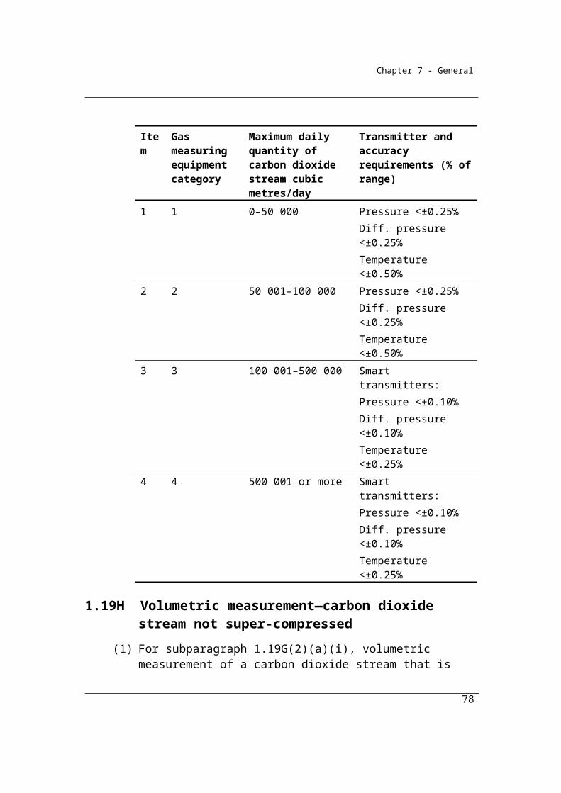
Chapter 7 - General
Chapter 2—Fuel combustion
Part 2.1—Preliminary
2.1 Outline of Chapter
The principle greenhouse gas generated by the combustion of fossil fuels for energy is carbon dioxide. The quantity of gas produced depends on the carbon content of the fuel and the degree to which the fuel is fully combusted. Small quantities of methane and nitrous oxide are also produced, depending on the actual combustion conditions. Methane may be generated when fuel is heated, but only partially burnt, and depends on combustion temperatures and the level of oxygen present. Nitrous oxide results from the reaction between nitrogen and oxygen in the combustion air.
The principle purpose of the combustion of fossil fuels in the Australian economy is for the consumption or use of energy. This chapter addresses the general case of the estimation of emissions from the combustion of fossil fuels for that purpose.
This Chapter provides for the following matters:(a) emissions released from the following sources:
(i) the combustion of solid fuels (see Part 2.2);(ii) the combustion of gaseous fuels (Part 2.3);
(iii) the combustion of liquid fuels (Part 2.4);(iv) fuel use by certain industries (Part 2.5);
(b) the measurement of fuels in blended fuels (Part 2.6);(c) the estimation of energy for certain purposes (Part 2.7).
Reporting context
Under subdivision 4.4.5 of the Regulations, Reporters should submit data for each individual fuel type on the quantity of fuel consumed for:
(a) electricity generation;
(b) transport (excluding international bunker fuels);
(c) carbon reductants or feedstocks;
(d) other stationary energy purposes; and
78
Chapter 7 - General
(e) fuels consumed without combustion.
For each fuel type the Reporter should also submit:
i) the amount of fuel consumed for each purpose (a) to (e);
ii) the emissions of each greenhouse gas for each purpose (a) to (d);
iii) the Method used to estimate the emissions (a) to (d); and
iv) the criterion used to estimate the amount of fuel consumed (a) to (e).
More detail on the reporting requirements are set out in Part 2.7A.
79
Chapter 7 - General
Part 2.2—Emissions released from the combustion of solid fuels
Division 2.2.1—Preliminary
2.2 Application
From the 2013-14 reporting year the measurement and reporting of emissions and
energy associated with the combustion of a solid fuel is optional if the quantity of
solid fuel combusted in a separate instance of a source is 1 tonne or less. Separate
instance of a source is defined in section 1.9A. Amounts below the reporting
threshold may still be reported if doing so is more efficient for the reporter.
This Part applies to emissions released from the combustion of solid fuel in relation to a separate instance of a source if the amount of solid fuel combusted in relation to the separate instance of the source is more than 1 tonne.
2.3 Available methods for estimating emissions of carbon dioxide, methane and nitrous oxide
(1) Subject to section 1.18, for estimating emissions released from the combustion of a solid fuel consumed from the operation of a facility during a year:
(a) one of the following methods must be used for estimating emissions of carbon dioxide:(i) subject to subsection (3), method 1 under section 2.4;
(ii) method 2 using an oxidation factor under section 2.5 or an estimated oxidation factor under section 2.6;
(iii) method 3 using an oxidation factor or an estimated oxidation factor under section 2.12;
(iv) method 4 under Part 1.3; and(b) method 1 under section 2.4 must be used for estimating emissions of
methane and nitrous oxide.
(2) However, for incidental emissions another method may be used that is consistent with the principles in section 1.13.
80
Chapter 7 - General
(3) Method 1 must not be used for estimating emissions of carbon dioxide for the main fuel combusted from the operation of the facility if:
(a) the principal activity of the facility is electricity generation (ANZSIC industry classification and code 2611); and
(b) the generating unit:(i) has the capacity to produce 30 megawatts or more of electricity;
and(ii) generates more than 50 000 megawatt hours of electricity in a
reporting year.Note: There is no method 2, 3 or 4 for paragraph (1)(b).
81
Chapter 7 - General
Division 2.2.2—Method 1—emissions of carbon dioxide, methane and nitrous oxide from solid fuels
2.4 Method 1—solid fuels
Method 1 is derived from the National Greenhouse Accounts national methodology as published in the National Inventory Report. Estimates of emissions from the combustion of individual solid fuel types are made by multiplying a (physical) quantity of fuel combusted by a fuel-specific energy content factor and a fuel-specific emission factor for each relevant greenhouse gas (in this case, carbon dioxide, methane and nitrous oxide).
The list of solid fuels for which emissions must be calculated is given in Table 2.2.2 (taken from Schedule 1 of the Regulations).
Energy content and emission factors required for the estimation of emissions from the combustion of solid fuels using this approach are given below. These factors are intended to be default factors – to be used in the absence of better information about the qualities of the fuels combusted at a particular facility. (If better information on fuel qualities or emissions is available, the Reporter may utilise Method 2, 3 or 4).
Once selected the energy content factor (ECi) for a particular fuel must be applied to all calculations of energy emissions from that fuel for a facility in the reporting year.
The emission factors for use in Method 1 have been estimated using the Australian Greenhouse Emissions Information System (AGEIS) operated by the Department on the Environment. Consequently, they are determined simultaneously with the production of Australia’s National Greenhouse Accounts ensuring that inventories of emissions at both facility and corporate levels are consistent with those of the national accounts.
For subparagraph 2.3(1)(a)(i), method 1 is:
i i ijoxecij
Q C EFE =
1 000
82
Chapter 7 - General
where:
Eij is the emissions of gas type (j), being carbon dioxide, methane or nitrous oxide, released from the combustion of fuel type (i) from the operation of the facility during the year measured in CO2-e tonnes.
Qi is the quantity of fuel type (i) measured in tonnes and estimated under Division 2.2.5.
ECi is the energy content factor of fuel type (i) estimated under section 6.5.
EFijoxec is the emission factor for each gas type (j) (which includes the effect of an oxidation factor) released from the combustion of fuel type (i) measured in kilograms of CO2-e per gigajoule according to source as mentioned in Schedule 1.
Table 2.2.2: Emission and energy content factors — solid fuels and certain coal-based products
Item Fuel combusted Energy content factor
GJ/t
Emission factorkg CO2-e/GJ
(RELEVANT OXIDATION FACTORS
INCORPORATED)
CO2 CH4 N2O
1 Bituminous coal 27.0 90.0 0.03 0.21A Sub-bituminous coal 21.0 90.0 0.03 0.21B Anthracite 29.0 90.0 0.03 0.22 Brown coal 10.2 93.5 0.02 0.43 Coking coal 30.0 91.8 0.02 0.24 Coal briquettes 22.1 95.0 0.07 0.35 Coal coke 27.0 107.0 0.04 0.26 Coal tar 37.5 81.8 0.03 0.27 Solid fossil fuels other than those
mentioned in items 1 to 522.1 95.0 0.07 0.3
83
Chapter 7 - General
Item Fuel combusted Energy content factor
GJ/t
Emission factorkg CO2-e/GJ
(RELEVANT OXIDATION FACTORS
INCORPORATED)
CO2 CH4 N2O
8 Industrial materials and tyres that are derived from fossil fuels, if recycled and combusted to produce heat or electricity
26.3 81.6 0.02 0.2
9 Non-biomass municipal materials, if recycled and combusted to produce heat or electricity
10.5 87.1 0.7 1.1
10 Dry wood 16.2 0.0 0.10 1.211 Green and air dried wood 10.4 0.0 0.10 1.212 Sulphite lyes 12.4 0.0 0.07 0.613 Bagasse 9.6 0.0 0.2 1.214 Biomass municipal and industrial
materials, if recycled and combusted to produce heat or electricity
12.2 0.0 0.7 1.1
15 Charcoal 31.1 0.0 4.8 1.116 Primary solid biomass fuels other
than those mentioned in items 10 to 15
12.2 0.0 0.7 1.1
Note Energy content factors for coal products are measured on an as combusted basis. The energy content for black coal and coking coal (metallurgical coal) is on a washed basis. Notes on the sources of the factors listed above can be found at Appendix 2A.
Additional coal classifications were introduced in the 2012-13 reporting year. The
classifications are defined in the NGER Regulations (Regulation 1.03) and are based
on Australian Standard AS2096-1987.
The new classifications are defined in NGER Regulation 1.03 as follows:
Anthracite means coal having a volatile matter of less than 14.0% on a dry
ash-free basis.
84
Chapter 7 - General
Bituminous coal means coal having:
(a) a volatile matter of not less than 14.0% on a dry ash-free basis; and
(b) gross specific energy of either:
(i) not less than 26.50 megajoules per kilogram on an ash-free moist
basis; or
(ii) not less than 24.00 megajoules per kilogram on an ash-free moist
basis if the crucible swelling number is not less than one.
Sub-bituminous coal means coal having a gross specific energy of:
(a) 19.00–23.99 megajoules per kilogram on an ash-free moist basis; or
(b) if the crucible swelling number is 0 or 1/2 — 19.00–26.49 megajoules per
kilogram on an ash-free moist basis.
Example
A facility consumes 20,000 tonnes of washed bituminous coal for a purpose other than for the production of electricity or coke. The Reporter elects to use Method 1 (Division 2.2.2) for each of the three greenhouse emission gases (j) (carbon dioxide, methane and nitrous oxide), for the fuel type bituminous coal. Emissions are estimated as follows:
where:
Eij is the emissions of gas type (j) released from the combustion of fuel type (i) from the operation of the facility during the year measured in CO2-e tonnes.
Qi is the quantity of fuel type (i) estimated under Division 2.2.5 measured in tonnes. In this case it is 20,000 tonnes of bituminous coal.
ECi is the energy content factor of fuel type (i) estimated under section 6.5. In this case it is assumed to be 27 gigajoules per tonne for bituminous coal.
85
Chapter 7 - General
EFijoxec is the emission factor for each gas (which includes the effect of a default oxidation factor) released from the combustion of fuel type (i) measured in kilograms of CO2-e per gigajoule according to source as mentioned in Schedule 1. In this case, for carbon dioxide, it is 90.0 kg CO2-e per gigajoule for bituminous coal. For methane, the emission factor is 0.03 kilograms per gigajoule and for nitrous oxide, 0.2 kilograms per gigajoule.
Emissions of greenhouse gases (carbon dioxide, methane and nitrous oxide) in tonnes of CO2-e are estimated as follows:
Emissions of carbon dioxide from combustion of bituminous coal:
= (20,000 x 27.0 x 90.0)/1,000
= 48,600 t CO2-e
Emissions of methane from combustion of bituminous coal:
= (20,000 x 27.0 x 0.03)/1,000
= 16 t CO2-e
Emissions of nitrous oxide from combustion of bituminous coal:
= (20,000 x 27.0 x 0.2)/1,000
= 108 t CO2-e
86
Chapter 7 - General
Division 2.2.3—Method 2—emissions from solid fuels
Subdivision 2.2.3.1—Method 2—estimating carbon dioxide using default oxidation factor
2.5 Method 2—estimating carbon dioxide using oxidation factor
Method 1 applies national emission factors to the estimation of emissions. This approach produces accurate estimates for each facility in the sense that they are expected to be neither over nor under-estimates, but the approach effectively averages out the variations in emission factors for the fuels that might be applicable for a particular facility. Better estimates of emissions at a particular facility may be obtained by sampling and analysing the fuels actually combusted at the facility for the intrinsic qualities of the fuels themselves that affect actual emission levels. These qualities include the carbon, ash and moisture content of a fuel and may vary reasonably significantly from source to source, particularly for coals.
Method 2 is derived from the methodologies published in the Technical Guidelines for the Generator Efficiency Standards program, released in December 2006 by the Australian Greenhouse Office, Department of Environment and Heritage and is designed to enable more accurate estimates of emissions to be made at a particular facility.
Under Method 2, representative and unbiased samples of fuels consumed must be obtained for analysis. Analysis of the fuels for carbon, energy, ash or moisture content must be done in accordance with listed Australian or international documentary standards or equivalent.
In order to deduct carbon dioxide captured for permanent storage reporters are required to use Method 2 or higher. These higher order methods provide a more accurate estimate of the carbon dioxide emissions than under Method 1, the default method. As the carbon dioxide captured is deducted from the emissions estimate it is necessary to have a greater level of accuracy in the emissions estimate than is achieved using Method 1.
87
Chapter 7 - General
Division 2.2.3 also sets out a further choice for the estimation of emissions from solid fuel combustion, which is to estimate emissions with a) an assumed oxidation factor (sub-division 2.2.3.1) or b) to estimate the oxidation level by reference to additional information about the fuels combusted by the facility (Sub-division 2.2.3.2).
For sub-division 2.2.3.1, oxidation factors are drawn from default factors utilised in the National Greenhouse Accounts.
Once the analysis of the fuel for carbon, ash and moisture has been completed, emissions may then be estimated in accordance with the equations specified in Section 2.5 (1) or 2.6 (1).
(1) For subparagraph 2.3(1)(a)(ii), method 2 is:
2
2 2
i i ico oxec ico co
Q EC EFE γRCCS
1 000
where:
Eico2 means the emissions of carbon dioxide released from the combustion of fuel type (i) from the operation of the facility during the year measured in CO2-e tonnes.
Qi is the quantity of fuel type (i) measured in tonnes and estimated under Division 2.2.5.
ECi is the energy content factor of fuel type (i) estimated under section 6.5.
EFico2oxec is the carbon dioxide emission factor for fuel type (i) measured in kilograms of CO2-e per gigajoule as worked out under subsection (2).
γ is the factor 1.861 × 10⁻³ for converting a quantity of carbon dioxide from cubic metres at standard conditions of pressure and temperature to CO2-e tonnes.
RCCSCO2 is carbon dioxide captured for permanent storage measured in cubic metres in accordance with Division 1.2.3.
(2) For EFico2oxec in subsection (1), estimate as follows:
88

Chapter 7 - General
2
2
ico ox,kgico oxec
i
EFEF = 1 000
EC
where:
EFico2ox,kg is the carbon dioxide emission factor for fuel type (i) measured in kilograms of CO2-e per kilogram of fuel as worked out under subsection (3).
ECi is the energy content factor of fuel type (i) as obtained under subsection (1).
(3) For EFico2ox,kg in subsection (2), work out as follows:
2
arico ox,kg s
CEF = OF 3.664
100
where:
Car is the percentage of carbon in fuel type (i), as received for the facility or as combusted from the operation of the facility, worked out under subsection (4).
OFs, or oxidation factor, is 1.0.
(4) For Car in subsection (3), work out as follows:
daf ar arar
C 100 - M - AC =
100
where:
Cdaf is the amount of carbon in fuel type (i) as a percentage of the dry ash-free mass of the fuel estimated using the sampling and analysis provided for in Subdivision 2.2.3.3.
Mar is the amount of moisture in fuel type (i) as a percentage of the as received or as combusted mass of the fuel estimated using the sampling and analysis provided for in Subdivision 2.2.3.3.
Aar is the amount of ash in fuel type (i) as a percentage of the as received or as combusted mass of the fuel estimated using the sampling and analysis provided for in Subdivision 2.2.3.3.
89
Chapter 7 - General
Table 2.2.3 Analysis of solid fuels: standards and frequency of analysis for energy, carbon, moisture and ash
Item Fuel combusted Parameter Standard Frequency
1 Bituminous coal Energy content factor
AS 1038.5—1998 Monthly sample composite
Carbon AS 1038.6.1—1997AS 1038.6.4—2005
Monthly sample composite
Moisture AS 1038.1—2001AS 1038.3—2000
Each delivery
Ash AS 1038.3—2000 Each delivery
1A Sub-bituminous coal Energy content factor
AS 1038.5—1998 Monthly sample composite
Carbon AS 1038.6.1—1997AS 1038.6.4—2005
Monthly sample composite
Moisture AS 1038.1—2001AS 1038.3—2000
Each delivery
Ash AS 1038.3—2000 Each delivery
1B Anthracite Energy content factor
AS 1038.5—1998 Monthly sample composite
Carbon AS 1038.6.1—1997AS 1038.6.4—2005
Monthly sample composite
Moisture AS 1038.1—2001AS 1038.3—2000
Each delivery
Ash AS 1038.3—2000 Each delivery
2 Brown coal Energy content factor
AS 1038.5—1998 Monthly sample composite
Carbon AS 2434.6—2002 Monthly sample composite
Moisture AS 2434.1—1999 Each delivery
Ash AS 2434.8—2002 Each delivery
3 Coking coal Energy content factor
AS 1038.5—1998 Monthly sample composite
Carbon AS 1038.6.1—1997AS 1038.6.4—2005
Monthly sample composite
90

Chapter 7 - General
Item Fuel combusted Parameter Standard Frequency
Moisture AS 1038.1—2001AS 1038.3—2000
Each delivery
Ash AS 1038.3—2000 Each delivery
4 Coal briquettes Energy content factor
AS 1038.5—1998 Monthly sample composite
Carbon AS 2434.6—2002 Monthly sample composite
Moisture AS 2434.1—1999 Each delivery
Ash AS 2434.8—2002 Each delivery
5 Coal coke Energy content factor
AS 1038.5—1998 Monthly sample composite
Carbon AS 1038.6.1—1997AS 1038.6.4—2005
Monthly sample composite
Moisture AS 1038.2—2006 Each delivery
Ash AS 1038.3—2000 Each delivery
6 Coal tar Energy content factor
N/A Monthly sample composite
Carbon N/A Monthly sample composite
Moisture N/A Each delivery
Ash N/A Each delivery
7 Solid fuels other than those mentioned in items 1 to 5
N/A N/A N/A
8 Industrial materials and tyres that are derived from fossil fuels, if recycled and combusted to produce heat or electricity
Energy content factor
CEN/TS 15400:2006 Monthly sample composite
Carbon CEN/TS 15407:2006 Monthly sample composite
Moisture CEN/TS 15414-3:2006
Each delivery
Ash CEN/TS 15403:2006 Each delivery
9 Non-biomass municipal materials, if recycled and combusted to produce heat or
Energy content factor
CEN/TS 15400:2006 Monthly sample composite
Carbon CEN/TS 15407:2006 Monthly sample composite
91

Chapter 7 - General
Item Fuel combusted Parameter Standard Frequency
electricity Moisture CEN/TS 15414-3:2006
Each delivery
Ash CEN/TS 15403:2006 Each delivery
10 Dry wood Energy content factor
CEN/TS 15400:2006 Monthly sample composite
Carbon CEN/TS 15407:2006 Monthly sample composite
Moisture CEN/TS 15414-3:2006CEN/TS 14774-3:2004
Each delivery
Ash CEN/TS 15403:2006 Each delivery
11 Green and air dried wood
Energy content factor
CEN/TS 15400:2006 Monthly sample composite
Carbon CEN/TS 15407:2006 Monthly sample composite
Moisture CEN/TS 15414-3:2006CEN/TS 14774-3:2004
Each delivery
Ash CEN/TS 15403:2006 Each delivery
12 Sulphite lyes Energy content factor
CEN/TS 15400:2006 Monthly sample composite
Carbon CEN/TS 15407:2006 Monthly sample composite
Moisture CEN/TS 15414-3:2006CEN/TS 14774-3:2004
Each delivery
Ash CEN/TS 15403:2006 Each delivery
13 Bagasse Energy content factor
CEN/TS 15400:2006 Monthly sample composite
Carbon CEN/TS 15407:2006 Monthly sample composite
Moisture CEN/TS 15414-3:2006CEN/TS 14774-3:2004
Each delivery
92
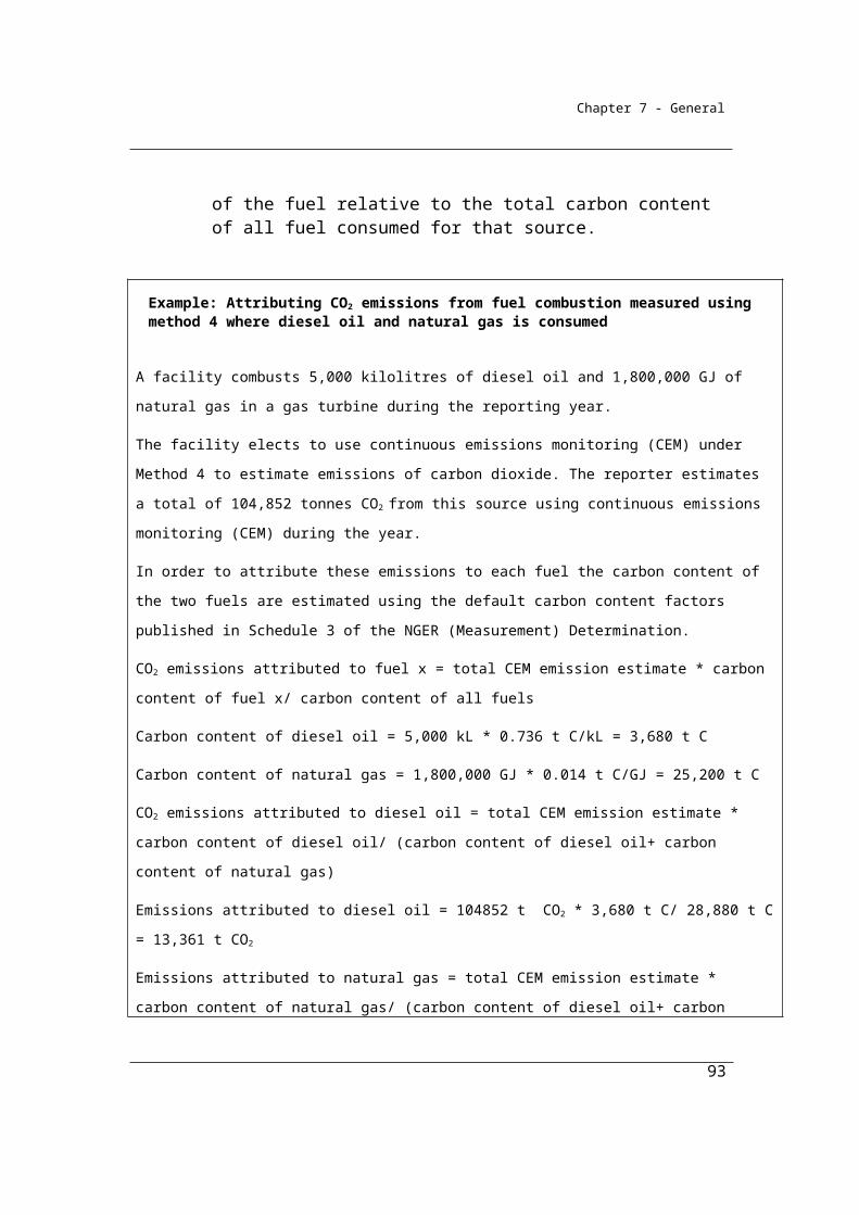
Chapter 7 - General
Item Fuel combusted Parameter Standard Frequency
Ash CEN/TS 15403:2006 Each delivery
14 Biomass municipal and industrial materials, if recycled and combusted to produce heat or electricity
Energy content factor
CEN/TS 15400:2006 Monthly sample composite
Carbon CEN/TS 15407:2006 Monthly sample composite
Moisture CEN/TS 15414-3:2006
Each delivery
Ash CEN/TS 15403:2006 Each delivery
15 Charcoal Energy content factor
CEN/TS 15400:2006 Monthly sample composite
Carbon CEN/TS 15407:2006 Monthly sample composite
Moisture CEN/TS 15414-3:2006
Each delivery
Ash CEN/TS 15403:2006 Each delivery
16 Primary solid biomass fuels other than those items mentioned in items 10 to 15
Energy content factor
CEN/TS 15400:2006 Monthly sample composite
Carbon CEN/TS 15407:2006 Monthly sample composite
Moisture CEN/TS 15414-3:2006CEN/TS 14774-3:2004
Each delivery
Ash CEN/TS 15403:2006 Each delivery
Example: A facility consumes 100,000 tonnes of bituminous coal with a carbon content of 75 per cent and an energy content of 28.5 gigajoules per tonne for purposes other than coke or electricity production. The Reporter elects to use Method 2 (Division 2.2.3) for the estimation of emissions of carbon dioxide and Method 1 (Division 2.2.2) for the estimation of emissions from methane and nitrous oxide.
Carbon dioxide emissions are estimated according to Method 2 as follows:
1. Estimate the carbon dioxide emission factor (EFico2ox,kg) for fuel type (i) as follows:
93

Chapter 7 - General
where:
EFico2ox,kg the carbon dioxide emission factor for fuel type (i) in kilograms of CO2-e per kilogram of fuel;
Car is the percentage of carbon in fuel type (i) as received for the facility. In this case the percentage of carbon in bituminous coal is estimated to be 75.
OFs, ,or oxidation factor, is 1.0:
= 75/100 x 1.0 x 3.664
= 2.75 kg of CO2-e per kg of fuel
2. Estimate the carbon dioxide emission factor for fuel type (i) measured in kilograms of
CO2-e per gigajoule as follows:
where:
EFico2ox,kg is the carbon dioxide emission factor for fuel type (i) measured in kilograms of CO2-e per kilogram of fuel.
ECi is the energy content factor of fuel type (i) estimated under section 6.5. In this case the energy content factor of bituminous coal is estimated to be 28.5 GJ/t.
= 2.75/28.5 x 1 000
= 96.4 kg of CO2-e per gigajoule
3. Estimate emissions as follows:
where:
94

Chapter 7 - General
Eico2 means the emissions of carbon dioxide released from the combustion of a fuel type (i) from the operation of the facility during the year measured in CO2-e tonnes.
Qi is the quantity of fuel type (i) measured in tonnes estimated under Division 2.2.5.
ECi is the energy content factor of fuel type (i) estimated under section 6.5.
γ is the factor 1.861 × 10 3 for converting a quantity of carbon dioxide from cubic metres at standard conditions of pressure and temperature to CO2 e tonnes.
RCCSCO2 is carbon dioxide captured for permanent storage measured in cubic metres in accordance with
Division 1.2.3.
EFico2oxec is the carbon dioxide emission factor for fuel type (i) measured in kilograms of CO2-e per gigajoule.
= 100,000 x 28.5 x 96.4/1 000
= 269,040tonnes of carbon dioxide emissions (CO2-e).
Methane and nitrous oxide emissions are estimated according to Method 1 as follows:
where:
Eij is the emissions of gas type (j) released from the combustion of fuel type (i) from the operation of the facility during the year measured in CO2-e tonnes.
Qi is the quantity of fuel type (i) estimated under Division 2.2.5 measured in tonnes.
ECi is the energy content factor of fuel type (i) estimated under section 6.5.
EFijoxec is the emission factor for each gas (which includes the effect of a default oxidation factor) released from the combustion of fuel type (i) measured in kilograms of CO2-e per gigajoule (Schedule 1).
Emissions of methane from combustion of bituminous coal:
= (100,000 x 28.5 x 0.03)/1 000
= 86 t CO2-e
Emissions of nitrous oxide from combustion of bituminous coal:
95
Chapter 7 - General
= (100,000 x 28.5 x 0.2)/1 000
= 570 t CO2-e
Subdivision 2.2.3.2—Method 2—estimating carbon dioxide using an estimated oxidation factor
2.6 Method 2—estimating carbon dioxide using an estimated oxidation factor
Sub-division 2.2.3.2 sets out the second option for the estimation of emissions from solid fuel combustion using an estimated oxidation level by reference to additional information about the fuels combusted by the facility. An alternative approach, using an assumed oxidation factor, is set out in sub-division 2.2.3.1.
(1) For subparagraph 2.3(1)(a)(ii), method 2 is:
2
2 2
i i ico oxec ico co
Q EC EFE γRCCS
1 000
where:
Eico2 means the emissions of carbon dioxide released from the combustion of fuel type (i) from the operation of the facility during the year measured in CO2-e tonnes.
Qi is the quantity of fuel type (i) measured in tonnes and estimated under Division 2.2.5.
ECi is the energy content factor of fuel type (i) estimated under section 6.5.
EFico2oxec is the amount worked out under subsection (2).
γ is the factor 1.861 × 10⁻³ for converting a quantity of carbon dioxide from cubic metres at standard conditions of pressure and temperature to CO2-e tonnes.
RCCSCO2 is carbon dioxide captured for permanent storage measured in cubic metres in accordance with Division 1.2.3.
96
Chapter 7 - General
(2) For EFico2oxec in subsection (1), work out as follows:
2
2
ico ox,kgico oxec
i
EFEF = 1 000
EC
where:
EFico2ox,kg is the carbon dioxide emission factor for the type of fuel measured in kilograms of CO2-e per kilogram of the type of fuel as worked out under subsection (3).
ECi is the energy content factor of fuel type (i) as obtained under subsection (1).
(3) For EFico2ox,kg in subsection (2), estimate as follows:
2
ar a ar
aox,kgico
C C AEF = 3.664100 100 C 100
where:
Car is the percentage of carbon in fuel type (i), as received for the facility or as combusted from the operation of the facility, worked out under subsection (4).
Ca is the amount of carbon in the ash estimated as a percentage of the as-sampled mass that is the weighted average of fly ash and ash by sampling and analysis in accordance with Subdivision 2.2.3.3.
Aar is the amount of ash in fuel type (i) as a percentage of the as received or as combusted mass of the fuel estimated using the sampling and analysis provided for in Subdivision 2.2.3.3.
(4) For Car, in subsection (3), estimate as follows:
daf ar arar
C 100 - M - AC =
100
where:
Cdaf is the amount of carbon in fuel type (i) as a percentage of the dry ash-free mass of the fuel estimated using the sampling and analysis provided for in Subdivision 2.2.3.3.
97
Chapter 7 - General
Mar is the amount of moisture in fuel type (i) as a percentage of the as received or as combusted mass of the fuel estimated using the sampling and analysis provided for in Subdivision 2.2.3.3.
Aar is the amount of ash in fuel type (i) as a percentage of the as received or as combusted mass of the fuel estimated using the sampling and analysis provided for in Subdivision 2.2.3.3.
Subdivision 2.2.3.3—Sampling and analysis for method 2 under sections 2.5 and 2.6
Under Method 2, representative and unbiased samples of fuels consumed must be obtained for analysis.
As coal is a heterogeneous material, for the sample to be truly representative it must contain the correct proportions of each particle size present, as well as the correct proportions of particles of varying impurity content. Therefore, in the process of collecting a representative sample, each particle in the lot must have an equal probability of being sampled (‘equal selection probability’); the representativeness of the sample being a function of the mass of the sample, or more correctly, the number of particles in the sample.
A mechanical sampling system, designed and operated in accordance with AS 4264 should be used to sample the coal or solid fuel. Ideally, this type of sampling system would be set up to obtain coal as it is either being loaded at the coal source or unloaded at the facility. One lot of coal will normally represent one day or one trainload of coal. If necessary, manual sampling of the coal may be used provided that the sampling equipment and procedure used is in accordance with AS 4264.
Sample preparation as required providing a laboratory sample for analysis is normally carried out in two steps:
Step 1: Initial crushing and subdivision of the samples as part of an operation that is integrated with the coal sampling;
Step 2: Final crushing and subdivision at the laboratory to provide the analysis sample.
98
Chapter 7 - General
Precision is defined as a measure of the extent to which the observations within a set agree with each other; usually expressed as twice the standard deviation (95% confidence level). Precision checks should be carried out on the sampling process to confirm that the sampling rate is acceptable. The procedure for determining the precision of coal sampling and sample preparation is prescribed in AS 4264.5. It is recommended that precision tests be undertaken on a yearly basis and whenever there is a change in the fuel source or a significant change in the quality characteristics of a particular fuel.
If several sources of fuels are being sampled through a given plant, sampling conditions and sample precision checks should be carried out on the source that exhibits the highest degree of heterogeneity.
Bias can be defined as the tendency to obtain a value that is either consistently higher or consistently lower than the reference value; in practice this is the difference between the reference value and the average result obtained from a large number of determinations. The recommended procedure for the estimation of bias in a coal sampling system is given in AS 4264.4. In the case of bias testing of mechanical samplers, the reference samples are usually stopped belt samples off a conveyor belt. For the purposes of verification of a coal sampling system, the coal samples taken for bias testing (pairs consisting of a reference sample and a sample taken by the coal sampler) should be analysed for total moisture and ash.
Bias testing should always be carried out on a new sampling system. For an existing system, the following verification procedure may be followed if there is some doubt about the conformance of the sampling system:
1. conduct a detailed technical audit of the sampling system;
2. correct any non-conformances that have been observed;
3. conduct a limited bias test on the system, usually with the coal that exhibits the widest stochastic variability in total moisture or ash, to provide a more quantitative verification that the sampling system is performing correctly.
99
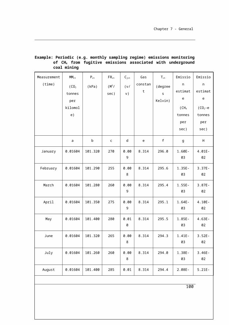
Chapter 7 - General
Analysis of the fuels for carbon, energy, ash or moisture content must be done in accordance with listed Australian or international documentary standards or by an on-line analyser in accordance with section 2.8 (3). The listing of applicable standards for the analysis of solid fuels is given below. Equivalent standards to those listed may also be used. Examples of equivalent standards include those produced by AS, NZ, ASTM, ISO and CEN standards organisations. The standards must be in force on the date stated in section 1.9. A NATA (National Association of Testing Authorities) accredited laboratory or similar laboratory complying with ISO 17025 should be used to conduct the analysis.
Minimum frequencies of analysis for solid fuels are also provided for in the table below.
2.7 General requirements for sampling solid fuels
(1) A sample of the solid fuel must be derived from a composite of amounts of the solid fuel combusted.
(2) The samples must be collected on enough occasions to produce a representative sample.
(3) The samples must also be free of bias so that any estimates are neither over nor under estimates of the true value.
(4) Bias must be tested in accordance with an appropriate standard (if any).Note: An appropriate standard for most solid mineral fuels is AS 4264.4—1996
Coal and coke—Sampling—Determination of precision and bias.
(5) The value obtained from the sample must only be used for the delivery period or consignment of the fuel for which it was intended to be representative.
2.8 General requirements for analysis of solid fuels
(1) A standard for analysis of a parameter of a solid fuel, and the minimum frequency of analysis of a solid fuel, is as set out in Schedule 2.
(2) A parameter of a solid fuel may also be analysed in accordance with a standard that is equivalent to a standard set out in Schedule 2.
(3) Analysis must be undertaken by an accredited laboratory that meets the requirements equivalent to those in AS ISO/IEC 17025:2005. However, analysis may be undertaken by an on-line analyser if:
100
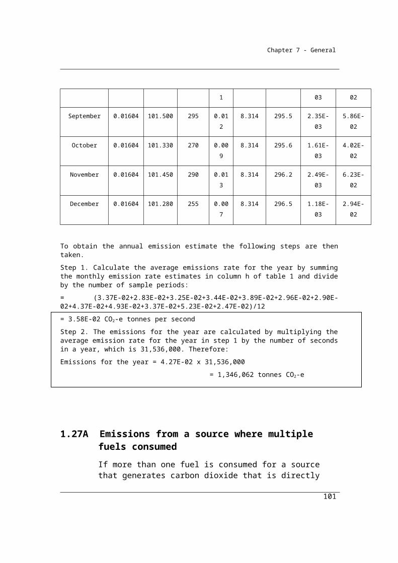
Chapter 7 - General
(a) the analyser is calibrated in accordance with an appropriate standard; and
(b) analysis undertaken to meet the standard is done by a laboratory that meets the requirements equivalent to those in AS ISO/IEC 17025:2005.
Note: An appropriate standard is AS 1038.24—1998, Coal and coke—Analysis and testing, Part 24: Guide to the evaluation of measurements made by on-line coal analysers.
(4) If a delivery of fuel lasts for a month or less, analysis must be conducted on a delivery basis.
(5) However, if the properties of the fuel do not change significantly between deliveries over a period of a month, analysis may be conducted on a monthly basis.
(6) If a delivery of fuel lasts for more than a month, and the properties of the fuel do not change significantly before the next delivery, analysis of the fuel may be conducted on a delivery basis rather than monthly basis.
2.9 Requirements for analysis of furnace ash and fly ash
Sampling of furnace and fly ash is needed if the method of sub-division 2.2.3.2 is adopted rather than the alternative method of sub-division 2.2.3.1.
It is recognised that the configuration of plant varies and measurement of carbon in ash should be based on representative operating conditions for the plant.
Furnace ash includes ash collected at the bottom of the furnace hopper of the coal unit and ash collected within the economiser hopper at the rear pass of the coal fired power plant. There is no standard procedure to collecting furnace ash or economiser hopper ash; however, in a wet extraction system, reasonable samples may be obtained by using sampling ladles to collect material from sluiceways. In a dry extraction system, good representative samples can be obtained directly from the conveyor. Particular care should be taken in attempting to obtain samples of furnace ash because of the inherent dangers associated with such operations. The Determination allows for alternative collection methods to be used to obtain samples where it is not feasible due to safety and operational considerations
101

Chapter 7 - General
The legislation sets out the minimum frequency for sampling for carbon in fly ash. It is acknowledged that some facilities sample on a more regular basis and these more frequent measurements should be incorporated into a facilities estimates.
Additional sampling should be undertaken for furnace and fly ash after a significant change in operating conditions as the amount and type of ash produced can vary significantly as a result of the change.
For facilities where load profiles vary significantly throughout the operation of the facility it is recommended that ash is sampled as a function of load.
For furnace ash and fly ash, analysis of the carbon content must be undertaken in accordance with AS 3583.2—1991 Determination of moisture content and AS 3583.3—1991 Determination of loss on ignition or a standard that is equivalent to those standards.
2.10 Requirements for sampling for carbon in furnace ash
(1) This section applies to furnace ash sampled for its carbon content if the ash is produced from the operation of a facility that is constituted by a plant.
(2) A sample of the ash must be derived from representative operating conditions in the plant.
(3) A sample of ash may be collected:(a) if contained in a wet extraction system—by using sampling ladles to
collect it from sluiceways; or(b) if contained in a dry extraction system—directly from the conveyer;
or(c) if it is not feasible to use one of the collection methods mentioned in
paragraph (a) or (b)—by using another collection method that provides representative ash sampling.
2.11 Sampling for carbon in fly ash
Fly ash must be sampled for its carbon content in accordance with: (a) a procedure set out in column 2 of an item in the following table, and
at a frequency set out in column 3 for that item; or(b) if it is not feasible to use one of the procedures mentioned in
paragraph (a)—another procedure that provides representative ash
102
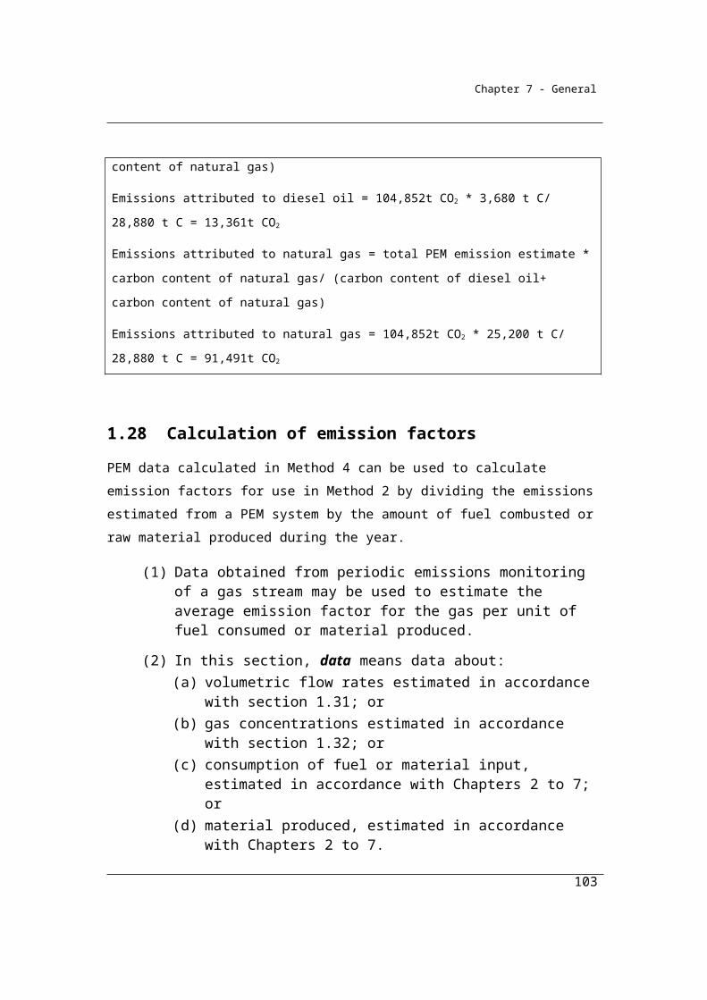
Chapter 7 - General
sampling, at least every two years, or after significant changes in operating conditions.
Item Procedure Frequency1 At the outlet of a boiler air heater or the inlet
to a flue gas cleaning plant using the isokinetic sampling method in AS 4323.1—1995 or AS 4323.2—1995, or in a standard that is equivalent to one of those standards
At least every 2 years, or after significant changes in operating conditions
2 By using standard industry ‘cegrit’ extraction equipment
At least every year, or after significant changes in operating conditions
3 By collecting fly ash from:(a) the fly ash collection hoppers of a flue gas
cleaning plant; or(b) downstream of fly ash collection hoppers
from ash silos or sluiceways
At least once a year, or after significant changes in operating conditions
4 From on-line carbon in ash analysers using sample extraction probes and infrared analysers
At least every 2 years, or after significant changes in operating conditions
103
Chapter 7 - General
Division 2.2.4—Method 3—Solid fuelsMethod 3 is a variation on Method 2. Method 3 provides for the same requirements as Method 2 except that sampling of fuels should also be conducted in accordance with the Australian or international standards listed in section 2.12 or by an equivalent standard. Once sampling of the fuel has been conducted in accordance with the standard, the analysis of the fuel for carbon, ash and moisture should be conducted as for Method 2. Emissions may then be estimated in accordance with the equations set out in sections 2.5 (1) or 2.6 (1) in Method 2.
2.12 Method 3—solid fuels using oxidation factor or an estimated oxidation factor
(1) For subparagraph 2.3(1)(a)(iii) and subject to this section, method 3 is the same as method 2 whether using the oxidation factor under section 2.5 or using an estimated oxidation factor under section 2.6.
(2) In applying method 2 as mentioned in subsection (1), solid fuels must be sampled in accordance with the appropriate standard mentioned in the table in subsection (3).
(3) A standard for sampling a solid fuel mentioned in column 2 of an item in the following table is as set out in column 3 for that item:
Item Fuel Standard1 Bituminous coal AS 4264.1—20091A Sub-bituminous coal AS 4264.1—20091B Anthracite AS 4264.1—20092 Brown coal AS 4264.3—19963 Coking coal (metallurgical coal) AS 4264.1—20094 Coal briquettes AS 4264.3—19965 Coal coke AS 4264.2—19966 Coal tar7 Industrial materials and tyres that are derived
from fossil fuels, if recycled and combusted to produce heat or electricity
CEN/TS 14778 – 1:2006CEN/TS 15442:2006
8 Non-biomass municipal materials, if recycled and combusted to produce heat or electricity
CEN/TS 14778 – 1:2005
104
Chapter 7 - General
Item Fuel StandardCEN/TS 15442:2006
9 Dry wood CEN/TS 14778 – 1:2005CEN/TS 15442:2006
10 Green and air dried wood CEN/TS 14778 – 1:2005CEN/TS 15442:2006
11 Sulphite lyes CEN/TS 14778 – 1:2005CEN/TS 15442:2006
12 Bagasse CEN/TS 14778 – 1:2005CEN/TS 15442:2006
13 Primary solid biomass other than items 9 to 12 and 14 to 15
CEN/TS 14778 – 1:2005CEN/TS 15442:2006
14 Charcoal CEN/TS 14778 – 1:2005CEN/TS 15442:2006
15 Biomass municipal and industrial materials, if recycled and combusted to produce heat or electricity
CEN/TS 14778 – 1:2005CEN/TS 15442:2006
(4) A solid fuel may also be sampled in accordance with a standard that is equivalent to a standard set out in the table in subsection (3).Note: The analysis is carried out in accordance with the same requirements as for
method 2.
105
Chapter 7 - General
Division 2.2.5—Measurement of consumption of solid fuels
2.13 Purpose of Division
This Division sets out how quantities of solid fuels combusted from the operation of a facility are to be estimated for the purpose of working out the emissions released from the combustion of that fuel.
Fuel types identified in the Determination are as specified in the Regulation, Schedule 1. The fuel types listed principally reflect the lists of fuels used by the Bureau of Resources and Energy Economics (BREE) to prepare Australia’s Energy Statistics and report, inter alia, on behalf of the Australian Government to the International Energy Agency.
The quantities of fuels consumed should exclude those quantities consumed for international transport purposes to reflect international reporting requirements for the national inventory. It is intended that this may be achieved by excluding international bunker fuels as defined in National Greenhouse and Energy Reporting Regulations 2008, Regulation 1.03, and that the point of differentiation between domestic and international consumption will be identical to that provided by the Customs Act 1901 which is used also for excise and GST purposes.
Division 2.2.5 specifies the criteria for the estimation of the amounts of each solid fuel type combusted from the operation of a facility during a year.
There are four criteria available for the estimation of quantities combusted reflecting differing levels of measurement effort and precision.
Under the National Greenhouse and Energy Reporting Regulations 2008, the criterion chosen by the Reporter to estimate combustion is required to be reported. Measuring equipment calibrated to a measurement requirement mentioned in Sections 2.16 and 2.17 refers to the standards required for measurement to support all commercial transactions covered by the National Measurement Act 1960 and associated instruments.
106

Chapter 7 - General
In Section 2.17 it is intended that measured data for fuels delivered (at the point of sale) would also meet the Criterion AAA under certain circumstances. These circumstances are that stocks of the fuel consumed at the facility are less than 5% of fuel consumption for the facility during the year and that the stock changes by less than 1% during the year. It is intended that the analysis may be conducted by the supplier.
The simplified measurement of consumption criterion is available in those cases where the Reporter does not purchase their fuel and where the Reporter also does not have metering equipment installed that meets the requirements of criterion AAA. In these cases, it is intended that Reporters should estimate consumption using metering devices or measurement techniques in practice in the industry. Such measurements would need to meet the criteria set out in section 1.13 of transparency, comparability, accuracy and completeness. Such data would be classified and reported as ‘BBB’ data.
The restriction on the choice of criteria at 2.14 (3) is designed to ensure time series
consistency of the measurements.
2.14 Criteria for measurement
(1) For the purpose of calculating the amount of solid fuel combusted from the operation of a facility during a year and, in particular, for Qi in sections 2.4, 2.5 and 2.6, the quantity of combustion must be estimated in accordance with this section.
Acquisition involves commercial transaction
(2) If the acquisition of the solid fuel involves a commercial transaction, the quantity of fuel combusted must be estimated using one of the following criteria:
(a) the amount of the solid fuel delivered for the facility during the year as evidenced by invoices issued by the vendor of the fuel (criterion A);
(b) as provided in section 2.15 (criterion AA);(c) as provided in section 2.16 (criterion AAA).
(3) If, during a year, criterion AA, or criterion AAA using paragraph 2.16(2)(a), is used to estimate the quantity of fuel combusted, then, in each year
107
Chapter 7 - General
following that year, only criterion AA, or criterion AAA using paragraph 2.16(2)(a), (respectively) is to be used.
Acquisition does not involve commercial transaction
(4) If the acquisition of the solid fuel does not involve a commercial transaction, the quantity of fuel combusted must be estimated using one of the following criteria:
(a) as provided in paragraph 2.16(2)(a) (criterion AAA);(b) as provided in section 2.17 (criterion BBB).
2.15 Indirect measurement at point of consumption—criterion AA
(1) For paragraph 2.14(2)(b), criterion AA is the amount of the solid fuel combusted from the operation of the facility during a year based on amounts delivered for the facility during the year as adjusted for the estimated change in the quantity of the stockpile of the fuel for the facility during the year.
(2) To work out the adjustment for the estimated change in the quantity of the stockpile of the fuel for the facility during the year, one of the following approaches must be used:
(a) the survey approach mentioned in subsection (2C);(b) the error allowance approach mentioned in subsection (2D).
(2A) The approach selected must be consistent with the principles mentioned in section 1.13.
(2B) The same approach, once selected, must be used for the facility for each year unless:
(a) there has been a material change in the management of the stockpile during the year; and
(b) the change in the management of the stockpile results in the approach selected being less accurate than the alternative approach.
(2C) The survey approach is as follows:
Step 1. Estimate the quantity of solid fuel in the stockpile by:
(a) working out the volume of the solid fuel in the stockpile using aerial or general survey in accordance with industry practice; and
108
Chapter 7 - General
(b) measuring the bulk density of the stockpile in accordance with subregulation (3).
Step 2. Replace the current book quantity with the quantity estimated under step 1.
Step 3. Maintain the book quantity replaced under step 2 by:
(a) adding deliveries made during the year, using:
(i) invoices received for solid fuel delivered to the facility; or
(ii) solid fuel sampling and measurements provided by measuring equipment calibrated to a measurement requirement; and
(b) deducting from the amount calculated under paragraph (a), solid fuel consumed by the facility.
Step 4. Use the book quantity maintained under step 3 to estimate the change in the quantity of the stockpile of the fuel.
Step 1. Estimate the quantity of solid fuel in the stockpile by:
(a) working out the volume of the solid fuel in the stockpile
using aerial or general survey in accordance with industry
practice; and
(b) measuring the bulk density of the stockpile in accordance
with subregulation (3).
Step 2. Replace the current book quantity with the quantity estimated
under step 1.
Step 3. Maintain the book quantity replaced under step 2 by:
(a) adding deliveries made during the year, using:
109
Chapter 7 - General
(i) invoices received for solid fuel delivered to the
facility; or
(ii) solid fuel sampling and measurements provided
by measuring equipment calibrated to a measurement
requirement; and
(b) deducting from the amount calculated under paragraph
(a), solid fuel consumed by the facility.
Step 4. Use the book quantity maintained under step 3 to estimate the
change in the quantity of the stockpile of the fuel.
Example - Estimating coal consumption using the survey approach
A facility reports consumption of sub-bituminous coal using the survey approach under
criteria AA.
Step 1: At 2pm on 27 June, near the end of the reporting year, the facility measures the bulk
density of the stockpile and estimates the volume of solid fuel in the stockpile. The
resulting estimate is a stockpile of 52,000 tonnes of sub-bituminous coal.
Step 2: The current book value is now 52,000 tonnes.
Step 3:
a) On 28 June a delivery of 21,530 tonnes is received by train and on 30 June a
delivery of 25,690 tonnes is received by train. The deliveries are evidenced by
invoices.
b) Sub bituminous coal consumption from 2pm-midnight on 27 June was estimated
to be 6,543 tonnes. Consumption was estimated to be 15,128, 16,425 and 15,303
tonnes on 28, 29 and 30 June respectively. Fuel consumption was estimated based
on the measured ‘as fired’ belt weigher readings adjusted for stocks held in unit
110

Chapter 7 - General
bunkers.
The book value as at 30 June is = Book value reported at step 2 + deliveries – fuel
consumed.
The book value as at 30 June is = 52,000 + 21,530 + 25,690 – 6,543 – 15,128 –
16,425 – 15,303 = 45,821 tonnes of sub-bituminous coal.
Step 4:
The book value at the end of the reporting period is 45,821 tonnes. This value is used to
estimate the change in the quantity of the stockpile of the fuel over the reporting year.
(2D)The error allowance approach is as follows:
Step 1. Estimate the quantity of the stockpile by:
(a) working out the volume of the solid fuel in the stockpile using aerial or general survey in accordance with industry practice; and
(b) measuring the bulk density of the stockpile in accordance with subregulation (3).
Step 2. Estimate an error tolerance for the quantity of solid fuel in the stockpile. The error tolerance is an estimate of the uncertainty of the quantity of solid fuel in the stockpile and must be:
(a) based on stockpile management practices at the facility and the uncertainty associated with the energy content and proportion of carbon in the solid fuel; and
(b) consistent with the general principles in section 1.13; and
(c) not more than 6% of the estimated value of the solid fuel in the stockpile worked out under step 1.
Step 3. Work out the percentage difference between the current book quantity and the quantity of solid fuel in the stockpile estimated under step 1.
111
Chapter 7 - General
Step 4. If the percentage difference worked out under step 3 is within the error tolerance worked out under step 2, use the book quantity to estimate the change in the quantity of the stockpile of the fuel.
Step 5. If the percentage difference worked out in step 3 is more than the error tolerance worked out in step 2:
(a) adjust the book quantity by the difference between the percentage worked out under step 3 and the error tolerance worked out under step 2; and
(b) use the book quantity adjusted under paragraph (a) to estimate the change in the quantity of the stockpile of the fuel.
Example A Estimating coal consumption using the error allowance approach – stockpile estimate within error tollerence
A facility reports consumption of sub-bituminous coal using the error allowance approach under
criteria AA. The book quantity of the stockpile as at 2pm on 27 June is 51,917 tonnes.
Step 1: At 2pm on 27 June, near the end of the reporting year, the facility measures the bulk
density of the stockpile and worked out the volume of solid fuel in the stockpile. The resulting
estimate is a stockpile of 52,851 tonnes of sub-bituminous coal.
Step 2: The error tolerance for the stockpile at this facility is estimated to be 4%.
Step 3: The current book value is 51,917 tonnes and the quantity of sub-bituminous coal in the
stockpile estimated under step 1 is estimated to be 52,851 tonnes. The difference between the two
estimates is 1.8%.
Step 4: The difference worked out under step 3 is less than the error tolerance of 4%. Therefore
112
Chapter 7 - General
the book value of is retained 51,917 tonnes is maintained.
On 28 June a delivery of 21,530 tonnes is received by train and on 30 June a delivery of 25,690
tonnes is received by train. The deliveries are evidenced by invoices.
Sub bituminous coal consumption from 2pm-midnight on 27 June was estimated to be 6,543
tonnes. Consumption was estimated to be 15,128, 16,425 and 15,303 tonnes on 28, 29 and
30 June respectively. Fuel consumption was estimated based on the measured ‘as fired’ belt
weigher readings adjusted for stocks held in unit bunkers.
The book value as at 30 June is = Book value as at 2pm on 27 June + deliveries – fuel consumed.
The book value as at 30 June is = 51,917 + 21,530 + 25,690 – 6,543 – 15,128 – 16,425 – 15,303 =
45,738 tonnes of sub-bituminous coal.
The book value at the end of the reporting period is 45,738 tonnes. This value is used to estimate
the change in the quantity of the stockpile of the fuel over the reporting year.
Example B Estimating coal consumption using the error allowance approach - stockpile estimate greater then error tollerence
A facility reports consumption of sub-bituminous coal using the error allowance approach under
criteria AA. The book quantity of the stockpile as at 2pm on 27June is 51,917 tonnes.
Step 1: At 2pm on 27 June, near the end of the reporting year, the facility measures the bulk
density of the stockpile and worked out the volume of solid fuel in the stockpile. The resulting
estimate is a stockpile of 54,625 tonnes of sub-bituminous coal.
Step 2: The error tolerance for the stockpile at this facility is estimated to be 4%.
Step 3: The current book value is 51,917 tonnes and the quantity of sub-bituminous coal in the
stockpile estimated under step 1 is estimated to be 54,625 tonnes. The stockpile estimate is 5.2%
greater than the current book value.
113
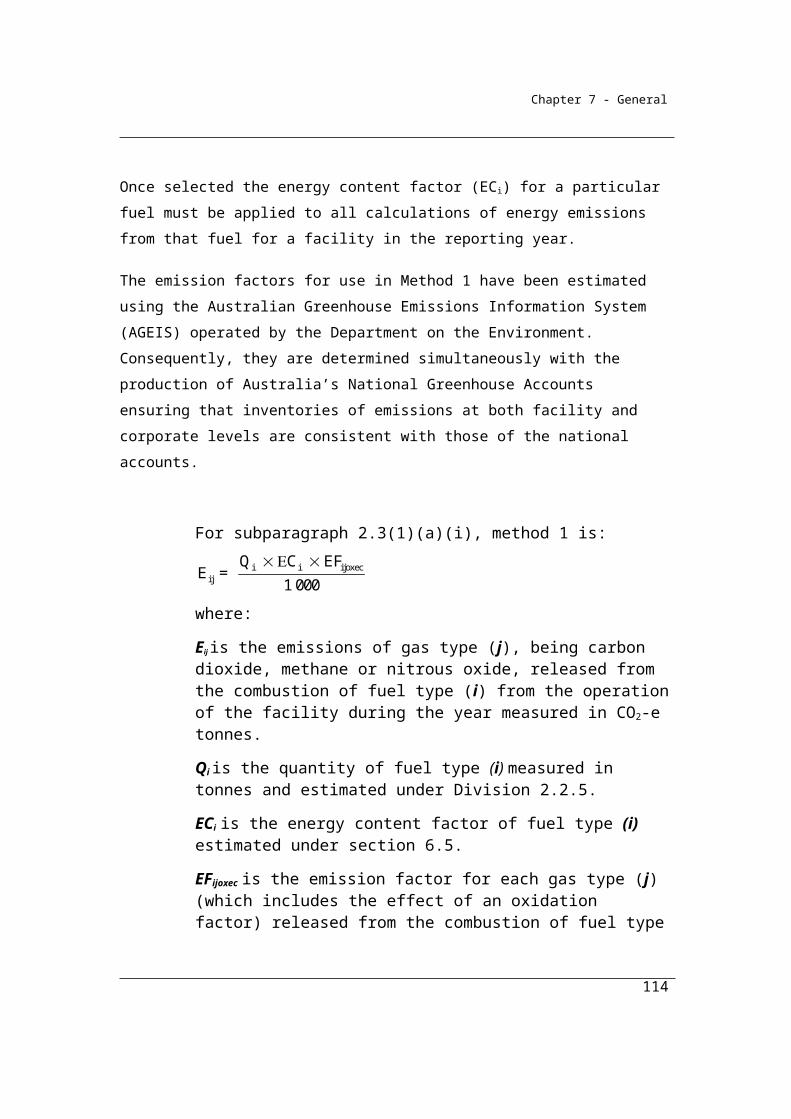
Chapter 7 - General
Step 4: Step 4 is not applicable because the difference worked out under step 3 is greater than the
error tolerance of 4.0%.
Step 5: The difference worked out under step 3 is greater than the error tolerance of 4%.
Therefore the book value is adjusted by the difference between the percentage worked out under
step 3 (5.2%) and the error tolerance worked out under step 2 (4.0%).
Revised book quantity = Current book value + Difference between estimated stockpile and the
book value – error tolerance * book value
Revised book quantity = 51,917 + (54,625-51,917) – (0.04 * 51,917) = 52,548 tonnes of sub-
bituminous coal.
On 28 June a delivery of 21,530 tonnes is received by train and on 30 June a delivery of 25,690
tonnes is received by train. The deliveries are evidenced by invoices.
Sub bituminous coal consumption from 2pm-midnight on 27 June was estimated to be 6,543
tonnes. Consumption was estimated to be 15,128, 16,425 and 15,303 tonnes on 28, 29 and
30 June respectively. Fuel consumption was estimated based on the measured ‘as fired’ belt
weigher readings adjusted for stocks held in unit bunkers.
The book value as at 30 June is = Book value as at 2pm on 27 June + deliveries – fuel consumed.
The book value as at 30 June is = 52,548 + 21,530 + 25,690 – 6,543 – 15,128 – 16,425 – 15,303 =
46,369 tonnes of sub-bituminous coal.
The book value at the end of the reporting period is 46,369 tonnes of sub-bituminous coal. This
value is used to estimate the change in the quantity of the stockpile of the fuel over the reporting
year.
(3) The bulk density of the stockpile must be measured in accordance with:(a) the procedure in ASTM D/6347/D 6347M-99; or(b) the following procedure:
114
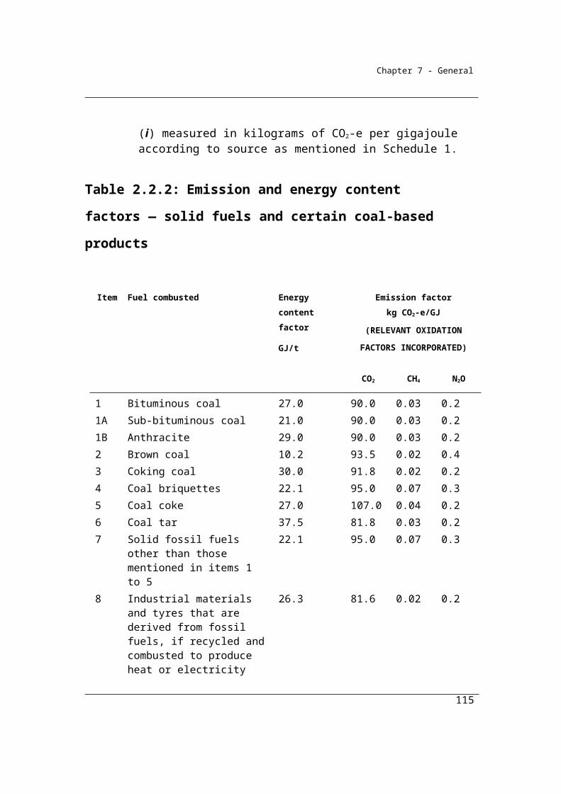
Chapter 7 - General
Step 1 If the mass of the stockpile:
(a) does not exceed 10% of the annual solid fuel combustion from the operation of a facility—extract a sample from the stockpile using a mechanical auger in accordance with ASTM D 4916-89; or
(b) exceeds 10% of the annual solid fuel combustion — extract a sample from the stockpile by coring.
Step 2 Weigh the mass of the sample extracted.
Step 3 Measure the volume of the hole from which the sample has been extracted.
Step 4 Divide the mass obtained in step 2 by the volume measured in step 3.
(4) Quantities of solid fuel delivered for the facility must be evidenced by invoices issued by the vendor of the fuel.
(5) In this section:
book quantity means the quantity recorded and maintained by the facility operator as the quantity of solid fuel in the stockpile.
2.16 Direct measurement at point of consumption—criterion AAA
(1) For paragraph 2.14(2)(c), criterion AAA is the measurement during a year of the solid fuel combusted from the operation of the facility.
(2) The measurement must be carried out either:(a) at the point of combustion using measuring equipment calibrated to a
measurement requirement; or(b) at the point of sale using measuring equipment calibrated to a
measurement requirement.
(3) Paragraph (2)(b) only applies if:(a) the change in the stockpile of the fuel for the facility for the year is
less than 1% of total combustion on average for the facility during the year; and
(b) the stockpile of the fuel for the facility at the beginning of the year is less than 5% of total combustion for the year.
115
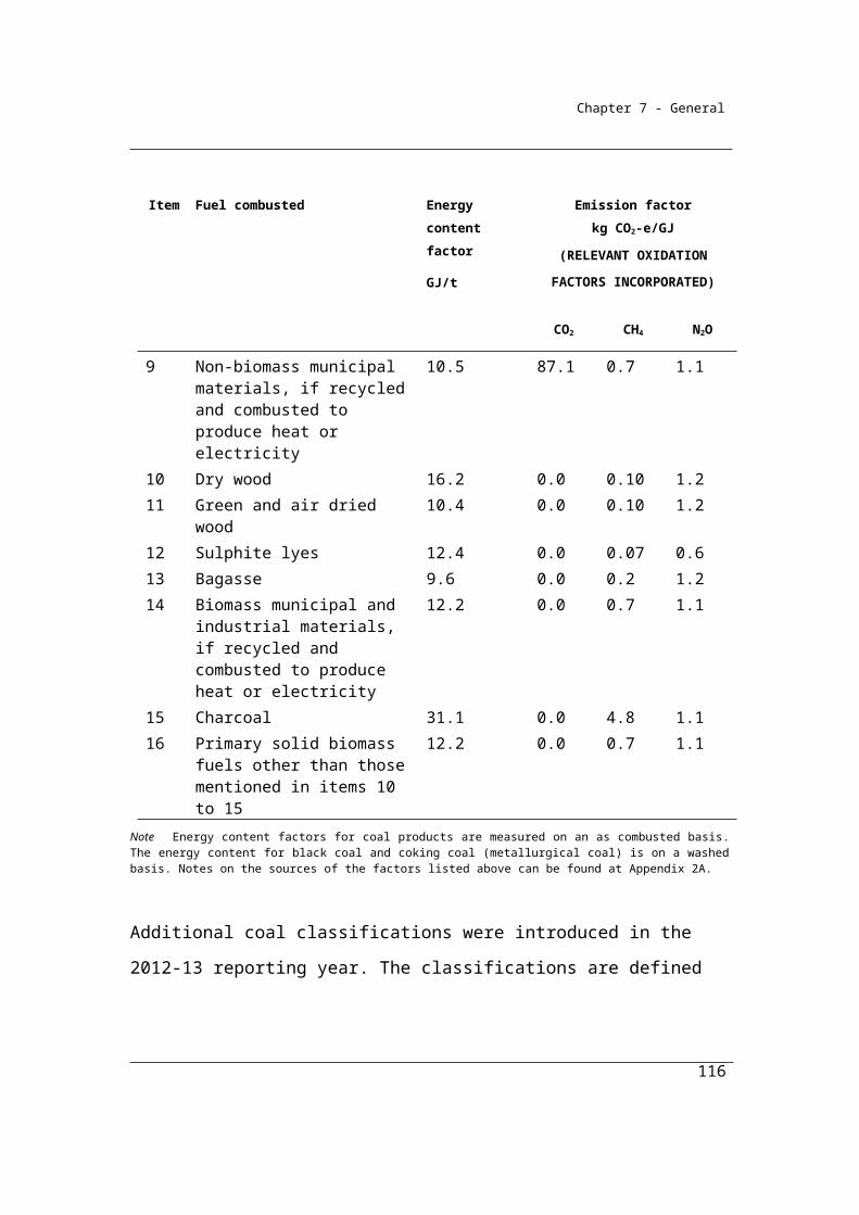
Chapter 7 - General
For AAA, calibration of the weighing system should be carried out as per the manufacturer’s instructions and at least on an annual basis. Some types of weighing systems, such as belt weighers, will require more frequent calibration. Calibration masses should be traceable to the appropriate National Standard of measurement.
The maximum permissible errors for weighers set out in the National Measurement Act 1960 and associated instruments are given in the table.
Maximum permissible errors for hopper weighers, belt weighers and automatic rail
weighbridges for initial verification and when the equipment is in-service
Weigher Accuracy Class Maximum Permissible Error
I.V. I.S.
Hopper weighers1 Class 0.2
Class 0.5
Class 1
Class 2
±0.10%
±0.25%
±0.50%
±1.00%
±0.2%
±0.5%
±1.0%
±2.0%
Belt weighers (dynamic conditions)2
Class 0.5
Class 1.0
Class 2.0
±0.25%
±0.5%
±1.0%
±0.5%
±1.0%
±2.0%
Automatic Rail-weighbridges (% or weight of single wagon or total train, as appropriate)2
Class 0.2
Class 0.5
Class 1
Class 2
±0.10%
±0.25%
±0.50%
±1.00%
±0.2%
±0.5%
±1.0%
±2.0%
I.V. = Initial verification
I.S. = In-service
Source: National Measurement Institute NMI R 107 Discontinuous Totalising Automatic Weighing Instruments
(Totalising Hopper Weighers)1
116
Chapter 7 - General
National Measurement Regulations 19992
Accuracy classes are defined in the National Measurement Regulations 1999 and NMI R 107 document
Maximum permissible errors for weigh bridges (static conditions) for initial verification and when the equipment is in-service
Maximum permissible
errorsfor loads m expressed in verification scale intervals e
initial
verification Class I Class II Class III Class IIII
±0.5 e
±1 e
±1.5 e
0 ≤ m ≤ 50 000
50 000 < m ≤ 200 000
200 000 < m
0 ≤ m ≤ 5 000
5 000 < m ≤ 20 000
20 000 < m ≤ 100 000
0 ≤ m ≤ 500
500 < m ≤ 2 000
2 000 < m ≤ 10 000
0 ≤ m ≤ 50
50 < m ≤ 200
200 < m ≤ 1 000
In service Class I Class II Class III Class IIII
±1.0 e
±2.0 e
±3.0 e
0 ≤ m ≤ 50 000
50 000 < m ≤ 200 000
200 000 < m
0 ≤ m ≤ 5 000
5 000 < m ≤ 20 000
20 000 < m ≤ 100 000
0 ≤ m ≤ 500
500 < m ≤ 2 000
2 000 < m ≤ 10 000
0 ≤ m ≤ 50
50 < m ≤ 200
200 < m ≤ 1 000
Source: National Measurement Institute NMI R 76-1 Non-automatic Weighing Instruments. Part 1:
Metrological and Technical Requirements — Tests
Accuracy classes for weigh bridges as defined in NMI R 76-1 document are:
Special accuracy – Class I
High accuracy – Class II
Medium accuracy – Class III
Ordinary accuracy – Class IIII
117
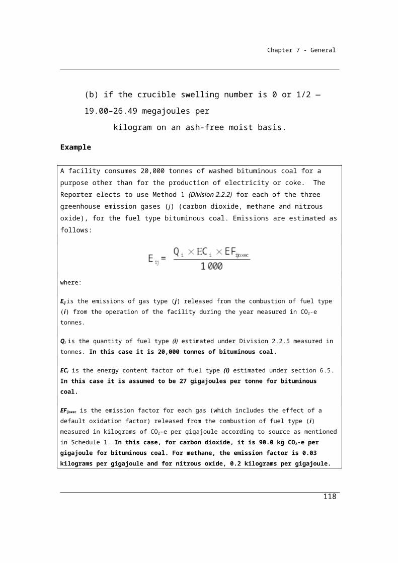
Chapter 7 - General
2.17 Simplified consumption measurements—criterion BBB
For paragraph 2.14(d), criterion BBB is the estimation of the solid fuel combusted during a year from the operation of the facility in accordance with industry practice if the equipment used to measure combustion of the fuel is not calibrated to a measurement requirement.Note: An estimate obtained using industry practice must be consistent with the
principles in section 1.13.
118

Chapter 7 - General
Part 2.3—Emissions released from the combustion of gaseous fuels
Division 2.3.1—Preliminary
2.18 ApplicationFrom the 2013-14 reporting year the measurement and reporting of emissions and energy associated with the combustion of a gaseous fuel is optional if the quantity of gaseous fuel combusted in a separate instance of a source is 1,000 cubic metres or less. Separate instance of a source is defined in section 1.9A. Amounts below the reporting threshold may still be reported if doing so is more efficient for the reporter.
This Part applies to emissions released from the combustion of gaseous fuels in relation to a separate instance of a source if the amount of gaseous fuel combusted in relation to the separate instance of the source is more than 1000 cubic metres.
2.19 Available methods
(1) Subject to section 1.18, for estimating emissions released from the combustion of a gaseous fuel consumed from the operation of a facility during a year:
(a) one of the following methods must be used for estimating emissions of carbon dioxide:(i) method 1 under section 2.20;
(ii) method 2 under section 2.21;(iii) method 3 under section 2.26;(iv) method 4 under Part 1.3; and
(b) one of the following methods must be used for estimating emissions of methane:(i) method 1 under section 2.20;
(ii) method 2 under section 2.27; and(c) method 1 under section 2.20 must be used for estimating emissions
of nitrous oxide.Note: The combustion of gaseous fuels releases emissions of carbon dioxide,
methane and nitrous oxide. Method 1 is used to estimate emissions of each of these gases. There is no method 3 or 4 for emissions of methane and no method 2, 3 or 4 for emissions of nitrous oxide.
119
Chapter 7 - General
(2) However, for incidental emissions another method may be used that is consistent with the principles in section 1.13.
(3) Method 1 must not be used for estimating emissions of carbon dioxide for the main fuel combusted from the operation of the facility if:
(a) the principal activity of the facility is electricity generation (ANZSIC industry classification and code 2611); and
(b) the generating unit:(i) has the capacity to produce 30 megawatts or more of electricity;
and(ii) generates more than 50 000 megawatt hours of electricity in a
reporting year.
120
Chapter 7 - General
Division 2.3.2—Method 1—emissions of carbon dioxide, methane and nitrous oxide
As for solid fuels, Method 1 for gaseous fuels is derived from the National Greenhouse Account national methodology as published in the National Inventory Report. Emissions for each gas type - carbon dioxide, methane or nitrous oxide - are estimated for individual fuel types by multiplying a (physical) quantity of fuel combusted by a fuel-specific energy content factor and a fuel-specific emission factor for each relevant greenhouse gas.
The list of gaseous fuels for which emissions must be calculated is given in Table 2.3.2A and 2.3.2B (taken from Schedule 1 of the National Greenhouse and Energy Reporting Regulations 2008).
Energy content and emission factors required for the estimation of emissions using this approach are given below. These factors are intended to be default factors – to be used in the absence of better information.
Once selected the energy content factor (ECi) for a particular fuel must be applied to all calculations of energy emissions from that fuel for a facility in the reporting year. The emission factors listed have been estimated using the Australian Greenhouse Emissions Information System (AGEIS) operated by the Department on the Environment. Consequently, they are determined simultaneously with the production of Australia’s National Greenhouse Accounts ensuring that Reporter inventories are consistent with those national accounts.
2.20 Method 1—emissions of carbon dioxide, methane and nitrous oxide
(1) For subparagraphs 2.19(1)(a)(i) and (b)(i) and paragraph 2.19(1)(c), method 1 for estimating emissions of carbon dioxide, methane and nitrous oxide is:
i i ijoxecij
Q C EFE =
1 000
where:
121

Chapter 7 - General
Eij is the emissions of gas type (j), being carbon dioxide, methane or nitrous oxide, from each gaseous fuel type (i) released from the operation of the facility during the year measured in CO2-e tonnes.
Qi is the quantity of fuel type (i) combusted, whether for stationary energy purposes or transport energy purposes, from the operation of the facility during the year measured in cubic metres or gigajoules and estimated under Division 2.3.6.
ECi is the energy content factor of fuel type (i) estimated under section 6.5.
EFijoxec is the emission factor for each gas type (j) released during the year (which includes the effect of an oxidation factor) measured in kilograms CO2-e per gigajoule of fuel type (i) according to source as mentioned in:
(a) for stationary energy purposes—Part 2 of Schedule 1; and(b) for transport energy purposes—Division 4.1 of Schedule 1.
Note: The combustion of gaseous fuels releases emissions of carbon dioxide, methane and nitrous oxide.
(2) In this section:
stationary energy purposes means purposes for which fuel is combusted that do not involve transport energy purposes.
transport energy purposes includes purposes for which fuel is combusted that consist of any of the following:
(a) transport by vehicles registered for road use;(b) rail transport;(c) marine navigation;(d) air transport.
Note: The combustion of gaseous fuels releases emissions of carbon dioxide, methane and nitrous oxide.
122
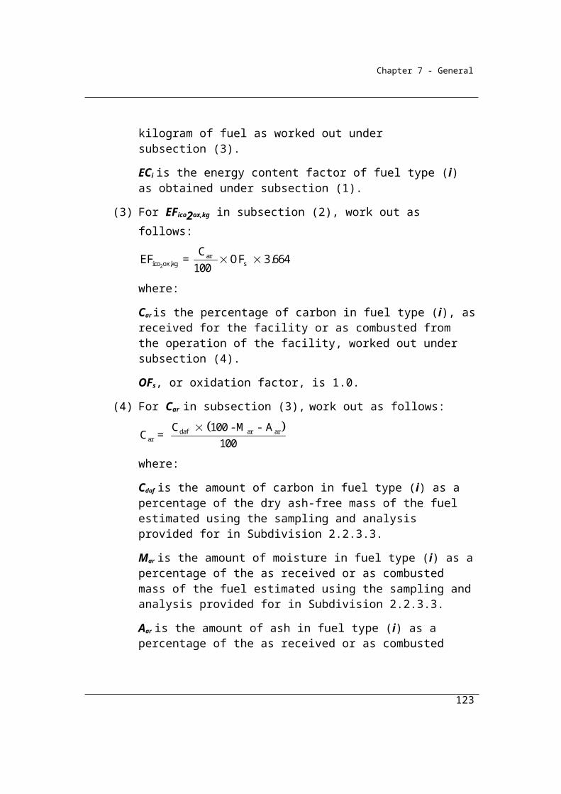
Chapter 7 - General
Table 2.3.2A Emission and energy content factors — gaseous fuels
Item Fuel combusted Energy content factor
(GJ/m3 unless otherwise indicated)
Emission factorkg CO2-e/GJ
(RELEVANT OXIDATION FACTORS INCORPORATED)
CO2 CH4 N2O
17 Natural gas distributed in a pipeline
39.3 × 10⁻³ 51.4 0.1 0.03
18 Coal seam methane that is captured for combustion
37.7 × 10⁻³ 51.4 0.2 0.03
19 Coal mine waste gas that is captured for combustion
37.7 × 10⁻³ 51.9 4.1 0.03
20 Compressed natural gas that has reverted to standard conditions
39.3 × 10⁻³ 51.4 0.1 0.03
21 Unprocessed natural gas 39.3 × 10⁻³ 51.4 0.1 0.0322 Ethane 62.9 × 10⁻³ 56.5 0.03 0.0323 Coke oven gas 18.1 × 10⁻³ 37.0 0.03 0.0524 Blast furnace gas 4.0 × 10⁻³ 234.0 0.0 0.0325 Town gas 39.0 × 10⁻³ 60.2 0.0 0.0326 Liquefied natural gas 25.3 GJ/kL 51.4 0.1 0.0327 Gaseous fossil fuels other than
those mentioned in items 17 to 2639.3 × 10-3 51.4 0.1 0.03
28 Landfill biogas that is captured for combustion (methane only)
37.7 × 10⁻³ 0.0 4.8 0.03
29 Sludge biogas that is captured for combustion (methane only)
37.7 × 10⁻³ 0.0 4.8 0.03
30 A biogas that is captured for combustion, other than those mentioned in items 28 and 29 (methane only)
37.7 × 10⁻³ 0.0 4.8 0.03
Notes on the sources of the factors listed above can be found at Appendix 2A.
123
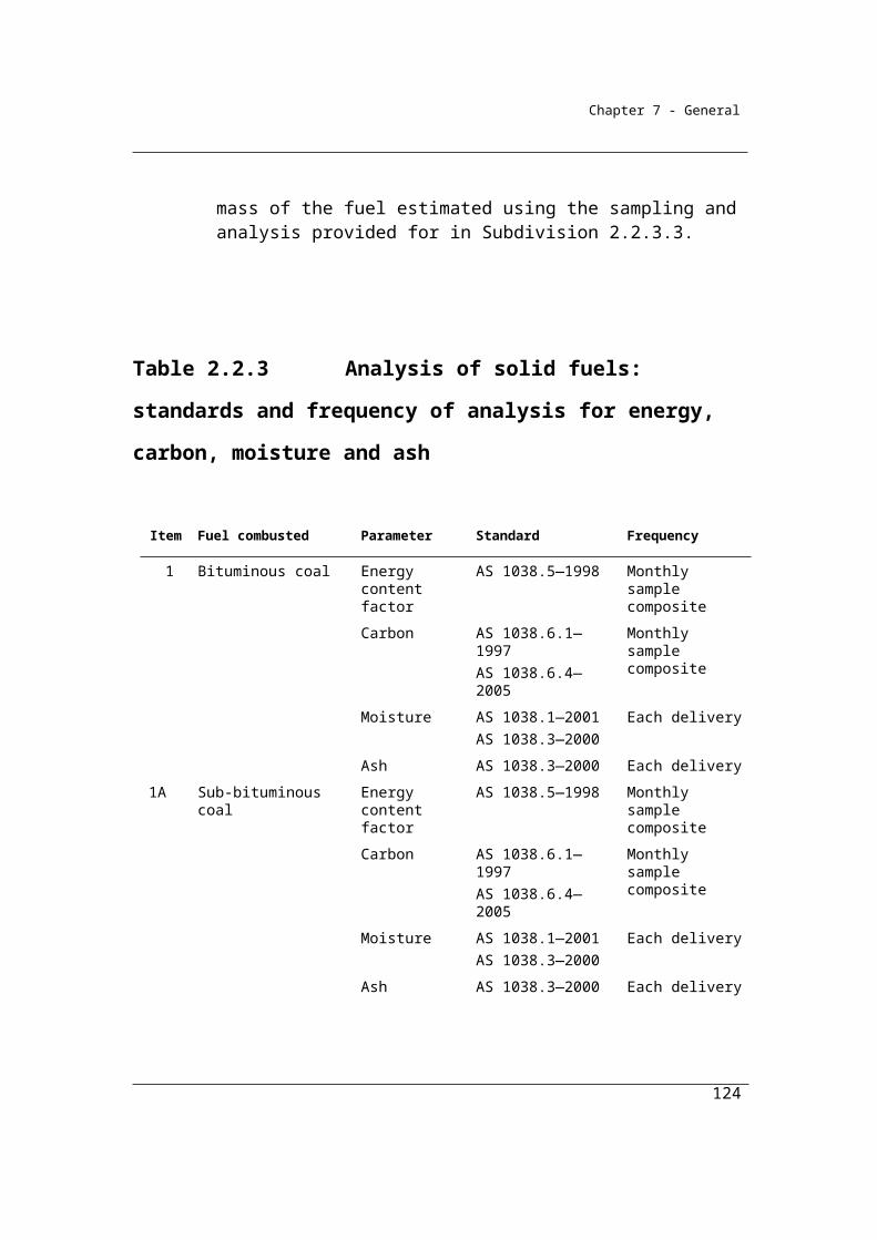
Chapter 7 - General
Table 2.3.2B Emissions and energy content factors — gaseous fuels for transport energy purposes
Item Fuel combusted Energy content factor
(GJ/kL unless otherwise indicated)
Emission factorkg CO2-e/GJ
(RELEVANT OXIDATION FACTORS
INCORPORATED)
CO2 CH4 N2O
62 Compressed natural gas that has reverted to standard conditions (light duty vehicles)
39.3 × 10⁻³ GJ/m3
51.4 6.5 0.3
63 Compressed natural gas that has reverted to standard conditions (heavy duty vehicles)
39.3 × 10⁻³ GJ/m3
51.4 2.5 0.3
63A Liquefied natural gas (light duty vehicles)
25.3 51.4 6.5 0.3
63B Liquefied natural gas (heavy duty vehicles)
25.3 51.4 2.5 0.3
Notes on the sources of the factors listed above can be found at Appendix 2A.
Definitions of the light and heavy duty vehicles for the purposes of applying gaseous fuels emissions factors can be found in
Appendix B: Definitions and interpretation.
124
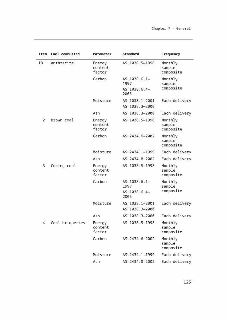
Chapter 7 - General
Division 2.3.3—Method 2—emissions of carbon dioxide from the combustion of gaseous fuels
Subdivision 2.3.3.1—Method 2—emissions of carbon dioxide from the combustion of gaseous fuels
2.21 Method 2—emissions of carbon dioxide from the combustion of gaseous fuels
As for solid fuels, Method 1 applies national average factors to the estimation of emissions. More accurate estimates of emissions at a facility level may be obtained by sampling and analysing fuels for qualities that affect emission levels when the fuel is combusted. These qualities include the composition of the constituent gases of the fuel combusted – for example, the share of methane in the combusted gas.
Method 2 is designed to enable more accurate estimates of emissions at a particular facility.
(1) For subparagraph 2.19(1)(a)(ii), method 2 for estimating emissions of carbon dioxide is:
2
2 2
i i ico oxec ico coRCCS
Q EC EFγ
1 000
E
where:
EiCO2 is emissions of carbon dioxide released from fuel type (i) combusted from the operation of the facility during the year measured in CO2-e tonnes.
Qi is the quantity of fuel type (i) combusted from the operation of the facility during the year measured in cubic metres or gigajoules and estimated under Division 2.3.6.
ECi is the energy content factor of fuel type (i) estimated under section 6.5.
EFiCO2oxec is the carbon dioxide emission factor for fuel type (i) measured in kilograms CO2-e per gigajoule and calculated in accordance with section 2.22.
125
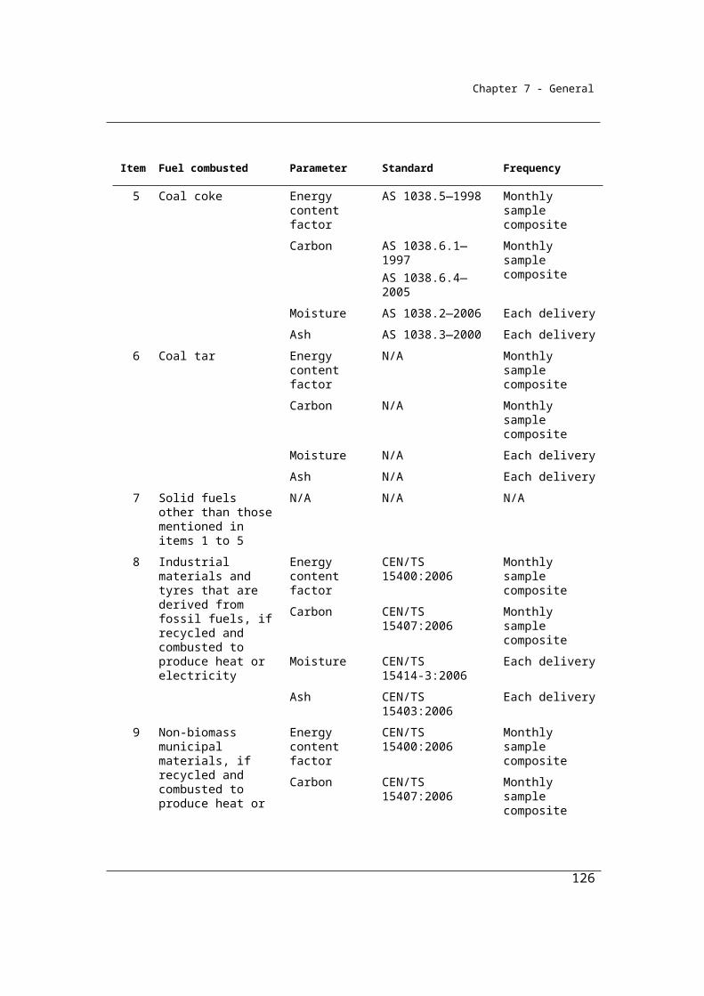
Chapter 7 - General
γ is the factor 1.861 × 10⁻³ for converting a quantity of carbon dioxide from cubic metres at standard conditions of pressure and temperature to CO2-e tonnes.
RCCSCO2 is carbon dioxide captured for permanent storage measured in cubic metres in accordance with Division 1.2.3.
2.22 Calculation of emission factors from combustion of gaseous fuel
(1) For section 2.21, the emission factor EFiCO2oxec from the combustion of fuel type (i) must be calculated from information on the composition of each component gas type (y) and must first estimate EFi,CO2,ox,kg in accordance with the following formula:
yy
y gi, CO2,ox,kg y
y total y
mwmol % ( ) 100 44.010 f OFVEF = d , (mw 100)
( ) ( )
where:
EFi,CO2,ox,kg is the carbon dioxide emission factor for fuel type (i), incorporating the effects of a default oxidation factor expressed as kilograms of carbon dioxide per kilogram of fuel.
moly%, for each component gas type (y), is that gas type’s share of 1 mole of fuel type (i), or that gas type’s share of the total volume of fuel type (i), expressed as a percentage.
mwy, for each component gas type (y), is the molecular weight of the component gas type (y) measured in kilograms per kilomole.
V is the volume of 1 kilomole of the gas at standard conditions and equal to 23.6444 cubic metres.
dy, total is as set out in subsection (2).
fy for each component gas type (y), is the number of carbon atoms in a molecule of the component gas type (y).
OFg is the oxidation factor 1.0 applicable to gaseous fuels.
(2) For subsection (1), the factor dy, total is worked out using the following formula:
126
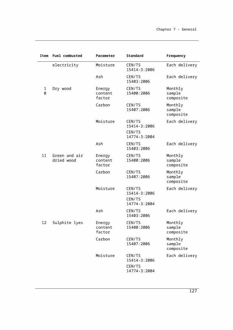
Chapter 7 - General
yy yy, total
mwd = mol % ( )V
where:
moly%, for each component gas type (y), is that gas type’s share of 1 mole of fuel type (i), or that gas type’s share of the total volume of fuel type (i), expressed as a percentage.
mwy, for each component gas type (y), is the molecular weight of the component gas type (y) measured in kilograms per kilomole.
(3) For subsection (1), the molecular weight and number of carbon atoms in a molecule of each component gas type (y) mentioned in column 2 of an item in the following table is as set out in columns 3 and 4, respectively, for the item:
Item Component gas y Molecular Wt (kg/kmole)
Number of carbon atoms in component molecules
1 Methane 16.043 12 Ethane 30.070 23 Propane 44.097 34 Butane 58.123 45 Pentane 72.150 56 Carbon monoxide 28.016 17 Hydrogen 2.016 08 Hydrogen sulphide 34.082 09 Oxygen 31.999 010 Water 18.015 011 Nitrogen 28.013 012 Argon 39.948 013 Carbon dioxide 44.010 1
(4) The carbon dioxide emission factor EFiCO2oxec derived from the calculation in subsection (1) must be expressed in terms of kilograms of carbon dioxide per gigajoule calculated using the following formula:
i
2 2i
i CO i ,CO ox,kgoxecECC
EF EF =
where:
127
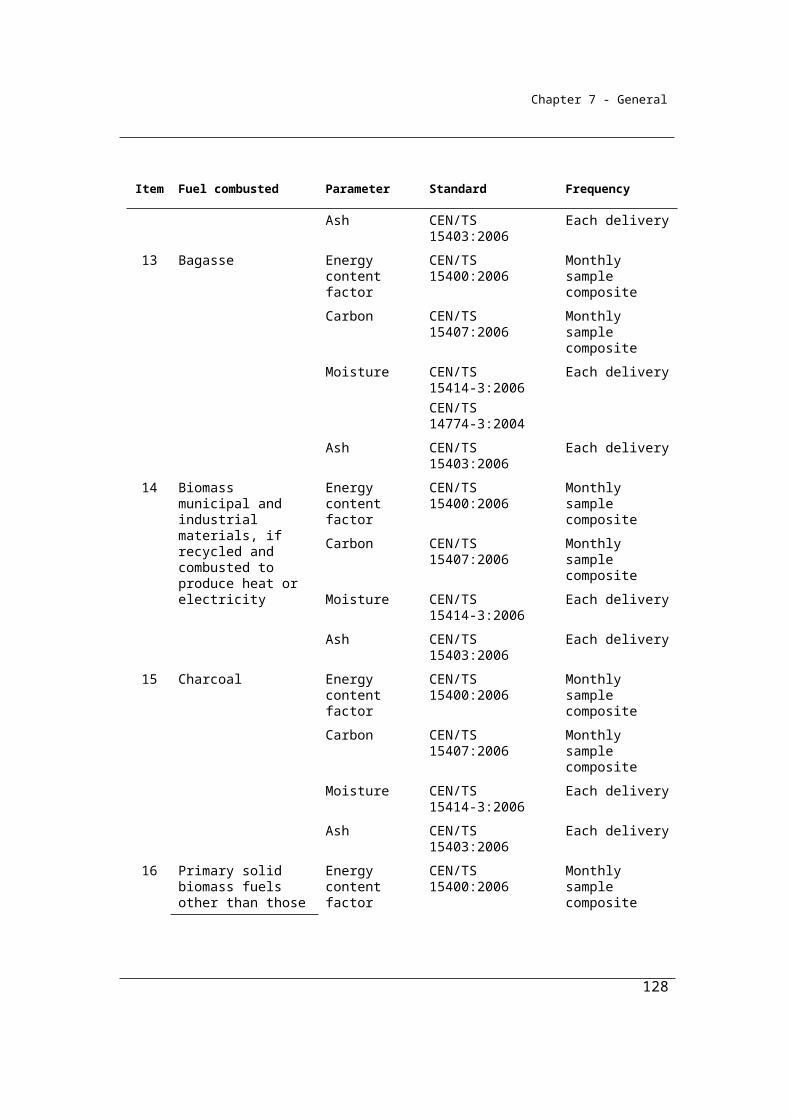
Chapter 7 - General
ECi is the energy content factor of fuel type (i), measured in gigajoules per cubic metre that is:
(a) mentioned in column 3 of Part 2 of Schedule 1; or(b) estimated by analysis under Subdivision 2.3.3.2.
Ci is the density of fuel type (i) expressed in kilograms of fuel per cubic metre as obtained under subsection 2.24(4).
Subdivision 2.3.3.2—Sampling and analysis
Under Method 2, representative and unbiased samples of fuels consumed must be obtained for analysis. Analysis of the fuels for composition of constituent gases must be done in accordance with listed Australian or international standards. A listing of applicable standards is given in Section 2.23. Equivalent standards may also be selected. Examples of equivalent standards include those produced by AS, NZ, ASTM, ISO and CEN standards organisations. The standards must be on the date stated in section 1.9.
A NATA (National Association of Testing Authorities) accredited laboratory or similar laboratory complying with ISO 17025 should be used to conduct the analysis.
Minimum frequencies of analysis of the gaseous fuels are also provided for in Section 2.25. With the results of the analysis, emissions may then be estimated in accordance the equations specified in Method 2.
2.23 General requirements for sampling under method 2
(1) A sample of the gaseous fuel must be derived from a composite of amounts of the gaseous fuel combusted.
(2) The samples must be collected on enough occasions to produce a representative sample.
(3) The samples must also be free of bias so that any estimates are neither over nor under estimates of the true value.
(4) Bias must be tested in accordance with an appropriate standard (if any).
(5) The value obtained from the samples must only be used for the delivery period, usage period or consignment of the gaseous fuel for which it was intended to be representative.
128
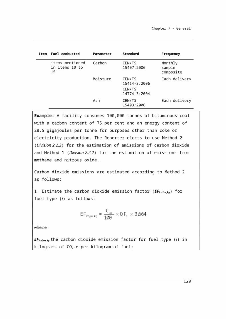
Chapter 7 - General
2.24 Standards for analysing samples of gaseous fuels
(1) Samples of gaseous fuels of a type mentioned in column 2 of an item in the following table must be analysed in accordance with one of the standards mentioned in:
(a) for analysis of energy content—column 3 for that item; and(b) for analysis of gas composition—column 4 for that item.
Item Fuel type Energy content Gas Composition1 Natural gas if
distributed in a pipeline
ASTM D 1826—94 (2003)ASTM D 7164—05ASTM 3588—98 (2003)ISO 6974
part 1 (2000)part 2 (2001) part 3 (2000) part 4 (2000) part 5 (2000)part 6 (2002)
ISO 6976:1995GPA 2172—96
ASTM D 1945—03ASTM D 1946—90 (2006)ISO 6974
part 1 (2000)part 2 (2001) part 3 (2000) part 4 (2000)part 5 (2000) part 6 (2002)
GPA 2145 – 03GPA 2261 – 00
2 Coal seam methane that is captured for combustion
ASTM D 1826—94 (2003)ASTM D 7164—05 ISO 6974
part 1 (2000)part 2 (2001) part 3 (2000) part 4 (2000) part 5 (2000)part 6 (2002)
ISO 6976:1995GPA 2172—96
ASTM D 1945—03ASTM D 1946—90 (2006)ISO 6974
part 1 (2000)part 2 (2001) part 3 (2000) part 4 (2000) part 5 (2000)part 6 (2002)
GPA 2145 – 03GPA 2261 – 00
3 Coal mine waste gas that is captured for combustion
ASTM D 1826 – 94 (2003)ASTM D 7164 – 05ASTM 3588—98
ASTM D 1945 – 03ASTM D 1946 – 90 (2006)ISO 6974
part 1 (2000)
129

Chapter 7 - General
Item Fuel type Energy content Gas Composition(2003)ISO 6974
part 1 (2000)part 2 (2001) part 3 (2000) part 4 (2000) part 5 (2000)part 6 (2002)
ISO 6976:1995GPA 2172—96
part 2 (2001) part 3 (2000) part 4 (2000) part 5 (2000)part 6 (2002)
GPA 2145 – 03GPA 2261 – 00
4 Compressed natural gas
ASTM 3588—98 (2003)
N/A
5 Unprocessed natural gas
ASTM D 1826—94 (2003)ASTM D 7164—05ISO 6974
part 1 (2000)part 2 (2001) part 3 (2000) part 4 (2000) part 5 (2000)part 6 (2002)
ISO 6976:1995GPA 2172—96
ASTM D 1945—03ASTM D 1946—90 (2006)ISO 6974
part 1 (2000)part 2 (2001) part 3 (2000) part 4 (2000)part 5 (2000) part 6 (2002)
GPA 2145 – 03GPA 2261 – 00
6 Ethane ASTM D 3588 – 98 (2003)IS0 6976:1995
ASTM D 1945 – 03ASTM D 1946 – 90 (2006)
7 Coke oven gas ASTM D 3588—98 (2003)ISO 6976:1995
ASTM D 1945—03ASTM D 1946—90 (2006)
8 Blast furnace gas
ASTM D 3588—98 (2003)ISO 6976:1995
ASTM D 1945—03ASTM D 1946—90 (2006)
9 Town gas ASTM D 1826—94 (2003)ASTM D 7164—05ISO 6974
part 1 (2000)
ASTM D 1945—03ASTM D 1946—90 (2006)ISO 6974
part 1 (2000)
130

Chapter 7 - General
Item Fuel type Energy content Gas Compositionpart 2 (2001) part 3 (2000) part 4 (2000) part 5 (2000)part 6 (2002)
ISO 6976:1995GPA 2172—96
part 2 (2001) part 3 (2000) part 4 (2000) part 5 (2000)part 6 (2002)
GPA 2145 – 03GPA 2261 – 00
10 Liquefied natural gas
ISO 6976:1995 ASTM D 1945 – 03ISO 6974
part 1 (2000)part 2 (2001) part 3 (2000) part 4 (2000) part 5 (2000)part 6 (2002)
11 Landfill biogas that is captured for combustion
ASTM D 1826—94 (2003)ASTM D 7164—05ISO 6974
part 1 (2000)part 2 (2001) part 3 (2000) part 4 (2000) part 5 (2000)part 6 (2002)
ISO 6976:1995GPA 2172—96
ASTM D 1945—03ASTM D 1946—90 (2006)ISO 6974
part 1 (2000)part 2 (2001) part 3 (2000) part 4 (2000) part 5 (2000)part 6 (2002)
GPA 2145 – 03GPA 2261 – 00
12 Sludge biogas that is captured for combustion
ASTM D 1826 – 94 (2003)ASTM D 7164 – 05ISO 6974
part 1 (2000)part 2 (2001) part 3 (2000) part 4 (2000) part 5 (2000)part 6 (2002)
ASTM D 1945 – 03 ASTM D 1946 – 90 (2006)ISO 6974
part 1 (2000)part 2 (2001) part 3 (2000) part 4 (2000) part 5 (2000)part 6 (2002)
GPA 2145 – 03
131

Chapter 7 - General
Item Fuel type Energy content Gas CompositionISO 6976:1995GPA 2172—96
GPA 2261 – 00
13 A biogas that is captured for combustion, other than those mentioned in items 11 and 12
ASTM D 1826—94 (2003)ASTM D 7164—05ISO 6974
part 1 (2000)part 2 (2001) part 3 (2000)
ASTM D 1945—03 ASTM D 1946—90 (2006)ISO 6974
part 1 (2000)part 2 (2001) part 3 (2000) part 4 (2000)
part 4 (2000) part 5 (2000)part 6 (2002)
part 5 (2000)part 6 (2002)
GPA 2145 – 03ISO 6976:1995GPA 2172—96
GPA 2261 – 00
(2) A gaseous fuel mentioned in column 2 of an item in the table in subsection (1) may also be analysed in accordance with a standard that is equivalent to a standard set out in column 3 and 4 of the item.
(3) The analysis must be undertaken:(a) by an accredited laboratory; or(b) by a laboratory that meets requirements that are equivalent to the
requirements in AS ISO/IEC 17025:2005; or(c) using an online analyser if:
(i) the online analyser is calibrated in accordance with an appropriate standard; and
(ii) the online analysis is undertaken in accordance with this section.Note: An example of an appropriate standard is ISO 6975:1997—Natural gas—
Extended analysis—Gas-chromatographic method.
(4) The density of a gaseous fuel mentioned in column 2 of an item in the table in subsection (1) must be analysed in accordance with ISO 6976:1995 or in accordance with a standard that is equivalent to that standard.
2.25 Frequency of analysis
Gaseous fuel of a type mentioned in column 2 of an item in the following table must be analysed for the parameter mentioned in column 3 for that item at least at the frequency mentioned in column 4 for that item.
132

Chapter 7 - General
Item Fuel Parameter Frequency1 Pipeline quality
gasesGas compositionEnergy content
MonthlyMonthly—if category 1 or 2 gas measuring equipment is usedContinuous—if category 3 or 4 gas measuring equipment is used
2 All other gases (including fugitive emissions)
Gas compositionEnergy content
Monthly, unless the reporting corporation or liable entity certifies in writing that such frequency of analysis will cause significant hardship or expense in which case the analysis may be undertaken at a frequency that will allow an unbiased estimate to be obtained
Note: The table in section 2.31 sets out the categories of gas measuring equipment.
133

Chapter 7 - General
Division 2.3.4—Method 3—emissions of carbon dioxide released from the combustion of gaseous fuels
As for solid fuels, Method 3 is a variation on Method 2. Method 3 provides for the same requirements as Method 2 except that sampling of fuels should also be conducted in accordance with the Australian or international standards listed below or by an equivalent standard. Once sampling of the fuel has been conducted in accordance with the standard, the analysis of the fuel should be conducted as for Method 2. Emissions may then be estimated in accordance with the equations specified in Section 2.21 (1) in Method 2.
2.26 Method 3—emissions of carbon dioxide from the combustion of gaseous fuels
(1) For subparagraph 2.19(1)(a)(iii) and subject to subsection (2), method 3 for estimating emissions of carbon dioxide is the same as method 2 under section 2.21.
(2) In applying method 2 under section 2.21, gaseous fuels must be sampled in accordance with a standard specified in the table in subsection (3).
(3) A standard for sampling a gaseous fuel mentioned column 2 of an item in the following table is the standard specified in column 3 for that item.
Item Gaseous fuel Standard 1 Natural gas if distributed in a
pipelineISO 10715:1997ASTM D 5287–97 (2002)ASTM F 307–02 (2007)ASTM D 5503–94 (2003)GPA 2166–05
2 Coal seam methane that is captured for combustion
ISO 10715:1997ASTM D 5287–97 (2002)ASTM F 307–02 (2007)ASTM D 5503–94 (2003)GPA 2166–05
3 Coal mine waste gas that is captured for combustion
ISO 10715:1997ASTM D 5287–97 (2002)ASTM F 307–02 (2007)
134
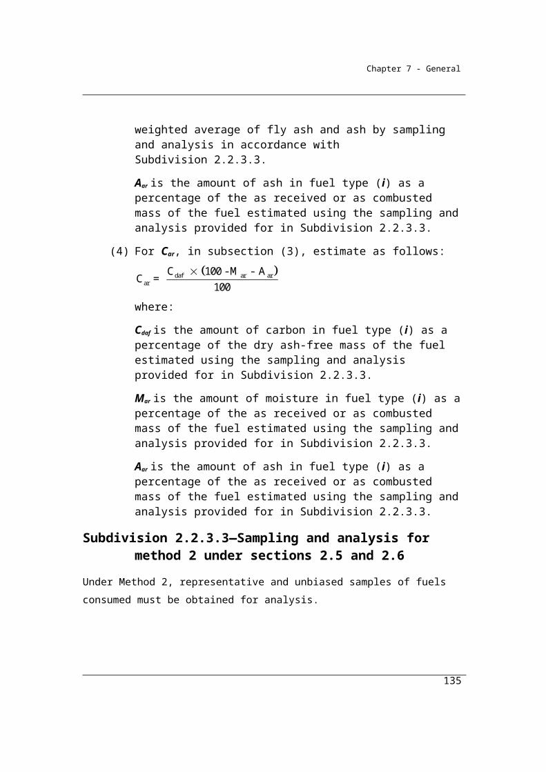
Chapter 7 - General
Item Gaseous fuel Standard ASTM D 5503–94 (2003)GPA 2166–05
4 Compressed natural gas ASTM F 307–02 (2007)5 Unprocessed natural gas ASTM D 5287–97 (2002)
ASTM F 307–02 (2007)ASTM D 5503–94 (2003)GPA 2166–05
6 Ethane ISO 10715:1997ASTM D 5287–97 (2002)ASTM F 307–02 (2007)ASTM D 5503–94 (2003)
7 Coke oven gas ISO 10715 -1997ASTM D 5287–97 (2002)ASTM F 307–02 (2007)ASTM D 5503–94 (2003)
8 Blast furnace gas ISO 10715:1997ASTM D 5287–97 (2002)ASTM F 307–02 (2007)ASTM D 5503–94 (2003)
9 Town gas ISO 10715:1997ASTM D 5287–97 (2002)ASTM F 307–02 (2007)ASTM D 5503–94 (2003)GPA 2166–05
10 Liquefied natural gas ISO 8943:200711 Landfill biogas that is captured
for combustion ISO 10715:1997ASTM D 5287–97 (2002)ASTM F 307–02 (2007)ASTM D 5503–94 (2003)GPA 2166–05
12 Sludge biogas that is captured for combustion
ISO 10715:1997ASTM D 5287–97 (2002)ASTM F 307–02 (2007)ASTM D 5503–94 (2003)GPA 2166–05
13 A biogas that is captured for ISO 10715:1997
135
Chapter 7 - General
Item Gaseous fuel Standard combustion, other than those mentioned in items 11 and 12
ASTM D 5287–97 (2002)ASTM F 307–02 (2007)ASTM D 5503–94 (2003)GPA 2166–05
(4) A gaseous fuel mentioned in column 2 of an item in the table in subsection (3) may also be sampled in accordance with a standard that is equivalent to a standard specified in column 3 for that item.
Division 2.3.5—Method 2—emissions of methane from the combustion of gaseous fuels
Section 2.27 sets out a Method 2 for methane emissions from the combustion of gaseous fuels. The quantity of methane emissions from the combustion of fuels depends on the equipment used. In the case of gaseous fuels, small variations in emissions are possible. Consequently, in this Method emissions may be estimated by substituting equipment-specific methane emission factors drawn from 2006 IPCC Guidelines for National Greenhouse Gas Inventories (Volume 2) for the methane emission factors listed in the Table in Section 2.20.
2.27 Method 2—emissions of methane from the combustion of gaseous fuels
(1) For subparagraph 2.19(1)(b)(ii) and subject to subsection (2), method 2 for estimating emissions of methane is the same as method 1 under section 2.20.
(2) In applying method 1 under section 2.20, the emission factor EFijoxec is to be obtained by using the equipment type emission factors set out in Volume 2, section 2.3.2.3 of the 2006 IPCC Guidelines corrected to gross calorific values.
136

Chapter 7 - General
Division 2.3.6—Measurement of quantity of gaseous fuels
2.28 Purpose of Division
This Division sets out how quantities of gaseous fuels combusted from the operation of a facility are to be estimated for the purpose of working out the emissions released from the combustion of that fuel.
The quantity of consumption of each of the fuel types specified in the Regulations, Schedule 1, are to be estimated according to one of the criterion set out below.
The fuel types listed principally reflect the lists of fuels used by the Department of Industry to prepare Australia’s Energy Statistics and report, inter alia, on behalf of the Australian Government to the International Energy Agency.
Separate estimates of the quantities of each fuel type consumed for the purpose of making electricity; for use as reductants or feedstocks; for use in transport (excluding international bunker fuels) and other stationary energy are required.
The quantities of fuels consumed for transport should exclude those quantities consumed for international transport purposes, if any, to reflect international reporting requirements for the national inventory. It is intended that this may be achieved by excluding international bunker fuels as defined in National Greenhouse and Energy Reporting Regulations 2008, Regulation 1.03, and that the point of differentiation between domestic and international consumption will be identical to that provided by the Customs Act 1901 which is used also for excise and GST purposes.
As for solid fuels, there are four criteria available for the estimation of quantities combusted. Under the National Greenhouse and Energy Reporting Regulations 2008, the criterion chosen will need to be reported.
The criteria include:
(a) Criterion A - the amount of the fuel delivered for the facility during the year as evidenced by invoices or delivery records issued by the vendor of the fuel (2.29);
(b) Criterion AA - indirect measurement at the point of consumption - based on the amount of fuel delivered for the facility and adjusted for changes in stocks (2.30);
137
Chapter 7 - General
(c) Criterion AAA - direct measurement at the point of consumption - based on the amount of fuel combusted as estimated by measurement equipment that comply with specified standards (2.31 – 2.37);
(d) Criterion BBB - simplified measurement of consumption (2.38).
Measuring equipment requirements set out in Sections 2.31 to 2.37 are drawn from the requirements set out in the Technical Guidelines for the Generator Efficiency Standards program for gaseous fuels. These standards have been broadened to provide for a measurement threshold that is not technology-specific (2.35 (4)), reflecting comparable State-specific thresholds for small to medium-sized consumers.
In Sections 2.31 it is intended that measured data for fuels delivered would also meet the Criterion AAA under certain circumstances. These circumstances are that stocks of the fuel consumed at the facility are less than 5% of fuel consumption for the facility during the year and that the stock changes by less than 1% during the year.
The simplified measurement of consumption criterion is available in those cases where the Reporter does not purchase fuel and where the Reporter also does not have metering equipment installed that meets the requirements of criterion AAA. In these cases, it is intended that Reporters should estimate consumption using metering devices or measurement techniques in practice in the industry. Such measurements would need to meet the criteria set out 1.13 - of transparency, comparability, accuracy and completeness, and would be classified and reported as ‘BBB’ data.
For landfill gas, the BBB criterion includes provision for the estimation of gas quantities based on the practice available under the NSW GGAS scheme – see the notice, Determining the energy content of waste methane under the generation rules, NSW IPART, 1 December 2006.
The restriction on the choice of criteria at 2.29 (3) is designed to ensure time series consistency of the measurements.
2.29 Criteria for measurement
(1) For the purposes of calculating the combustion of gaseous fuel from the operation of a facility for a year and, in particular, for Qi in sections 2.20
138
Chapter 7 - General
and 2.21, the combustion must be estimated in accordance with this section.
Acquisition involves commercial transaction
(2) If the acquisition of the gaseous fuel involves a commercial transaction, the quantity of fuel combusted must be estimated using one of the following criteria:
(a) the amount of the gaseous fuel, expressed in cubic metres or gigajoules, delivered for the facility during the year as evidenced by invoices issued by the vendor of the fuel (criterion A);
(b) as provided in section 2.30 (criterion AA);(c) as provided in section 2.31 (criterion AAA).
(3) If, during a year, criterion AA, or criterion AAA using paragraph 2.31(3)(a), is used to estimate the quantity of fuel combusted, then, in each year following that year, only criterion AA, or criterion AAA using paragraph 2.31(3)(a), (respectively) is to be used.
Acquisition does not involve commercial transaction
(4) If the acquisition of the gaseous fuel does not involve a commercial transaction, the quantity of fuel combusted must be estimated using one of the following criteria:
(a) as provided in section 2.31 (criterion AAA);(b) as provided in section 2.38 (criterion BBB).
2.30 Indirect measurement—criterion AA
For paragraph 2.29(2)(b), criterion AA is the amount of a gaseous fuel combusted from the operation of the facility during the year based on amounts delivered during the year (evidenced by invoices) as adjusted for the estimated change in the quantity of the stockpile of the fuel for the facility during the year.
2.31 Direct measurement—criterion AAA
(1) For paragraph 2.29(2)(c), criterion AAA is the measurement during the year of a gaseous fuel combusted from the operation of the facility.
(2) In measuring the quantity of gaseous fuel, the quantities of gas must be measured:
(a) using volumetric measurement in accordance with:(i) for gases other than super-compressed gases—section 2.32; and
139
Chapter 7 - General
(ii) for super-compressed gases—sections 2.32 and 2.33; and(b) using gas measuring equipment that complies with section 2.34.
(3) The measurement must be either:(a) carried out at the point of combustion using gas measuring
equipment that:(i) is in a category specified in column 2 of an item in the table in
subsection (4) according to the maximum daily quantity of gas combusted from the operation of the facility specified, for the item, in column 3 of the table; and
(ii) complies with the transmitter and accuracy requirements specified, for the item, in column 4 of the table, if the requirements are applicable to the gas measuring equipment being used; or
(b) carried out at the point of sale of the gaseous fuels using measuring equipment that complies with paragraph (a).
(4) For subsection (3), the table is as follows:
Item Gas measuring equipment category
Maximum daily quantity of gas combusted (GJ/day)
Transmitter and accuracy requirements (% of range)
1 1 0–1750 Pressure <±0.25%Diff. pressure <±0.25%Temperature <±0.50%
2 2 1751–3500 Pressure <±0.25%Diff. pressure <±0.25%Temperature <±0.50%
3 3 3501–17500 Smart transmitters:Pressure <±0.10%Diff. pressure <±0.10%Temperature <±0.25%
4 4 17501 or more Smart transmitters: Pressure <±0.10%Diff. pressure <±0.10%Temperature <±0.25%
(5) Paragraph (3)(b) only applies if:
140
Chapter 7 - General
(a) the change in the stockpile of the fuel for the facility for the year is less than 1% of total consumption on average for the facility during the year; and
(b) the stockpile of the fuel for the facility at the beginning of the year is less than 5% of total consumption of the fuel from the operation of the facility during the year.
2.32 Volumetric measurement—all natural gases
(1) For subparagraph 2.31(2)(a)(i) and (ii), volumetric measurement must be calculated at standard conditions and expressed in cubic metres.
(2) The volumetric measurement must be calculated using a flow computer that measures and analyses the following at the delivery location of the gaseous fuel:
(a) flow;(b) relative density;(c) gas composition.
(3) The volumetric flow rate must be:(a) continuously recorded; and(b) continuously integrated using an integration device.
(3A) The integration device must be isolated from the flow computer in such a way that, if the computer fails, the integration device will retain:
(a) the last reading that was on the computer immediately before the failure; or
(b) the previously stored information that was on the computer immediately before the failure.
(4) All measurements, calculations and procedures used in determining volume (except for any correction for deviation from the ideal gas law) must be made in accordance with:
(a) the instructions mentioned in subsection (5); or(b) an appropriate internationally recognised standard or code.
Note: An example of an internationally recognised equivalent standard is New Zealand standard NZS 5259:2004.
(5) For paragraph (4)(a), the instructions are those mentioned in:(a) for orifice plate measuring systems:
(i) the publication entitled AGA Report No. 3, Orifice Metering of Natural Gas and Other Related Hydrocarbon Fluids Part 3:
141
Chapter 7 - General
Natural Gas Applications, published by the American Gas Association in August 1992; or
(ii) Parts 1 to 4 of the publication entitled ANSI/API MPMS Chapter 14.3 Part 2 (R2011) Natural Gas Fluids Measurement: Concentric, Square-Edged Orifice Meters - Part 2: Specification and Installation Requirements, 4th edition, published by the American Petroleum Institute on 30 April 2000;
(b) for turbine measuring systems—the publication entitled AGA Report No. 7, Measurement of Natural Gas by Turbine Meter (2006), published by the American Gas Association on 1 January 2006;
(c) for positive displacement measuring systems—the publication entitled ANSI B109.3—2000, Rotary Type Gas Displacement Meters, published by the American Gas Association on 13 April 2000.
(6) Measurements must comply with Australian legal units of measurement.
(7) Standard conditions means, as measured on a dry gas basis:(a) air pressure of 101.325 kilopascals; and(b) air temperature of 15.0 degrees Celsius; and(c) air density of 1.225 kilograms per cubic metre.
2.33 Volumetric measurement—super-compressed gases
(1) For subparagraph 2.31(2)(a)(ii), this section applies in relation to measuring the volume of super-compressed natural gases.
(2) If it is necessary to correct the volume for deviation from the ideal gas law, the correction must be determined using the relevant method set out in the publication entitled AGA Report No. 8, Compressibility Factor of Natural Gas and Related Hydrocarbon Gases (1994), published by the American Gas Association on 1 January 1994.
(3) The measuring equipment used must calculate super-compressibility by:(a) if the measuring equipment is category 3 or 4 equipment in
accordance with the table in section 2.31—using gas composition data; or
(b) if the measuring equipment is category 1 or 2 equipment in accordance with the table in section 2.31—using an alternative method set out in the publication entitled AGA Report No. 8, Compressibility Factor of Natural Gas and Related Hydrocarbon Gases (1994), published by the American Gas Association on 1 January 1994.
142
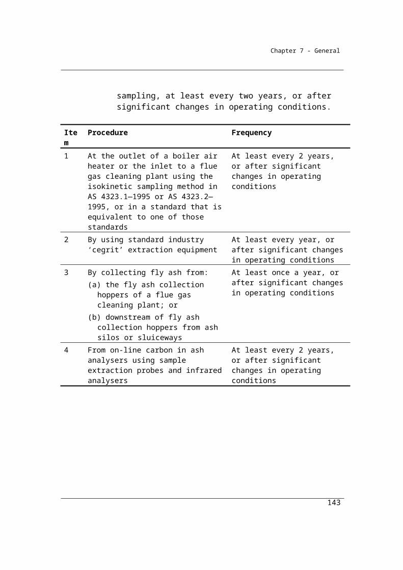
Chapter 7 - General
2.34 Gas measuring equipment—requirements
For paragraph 2.31(2)(b), gas measuring equipment that is category 3 or 4 equipment in accordance with column 2 of the table in section 2.31 must comply with the following requirements:
(a) if the equipment uses flow devices—the requirements relating to flow devices set out in section 2.35;
(b) if the equipment uses flow computers—the requirement relating to flow computers set out in section 2.36;
(c) if the equipment uses gas chromatographs—the requirements relating to gas chromatographs set out in section 2.37.
2.35 Flow devices—requirements
(1A) This section is made for paragraph 2.34(a).
(1) If the measuring equipment has flow devices that use orifice measuring systems, the flow devices must be constructed in a manner that ensures that the maximum uncertainty of the discharge coefficient is not greater than ±1.5%.Note: The publication entitled AGA Report No. 3, Orifice Metering of Natural Gas
and Other Related Hydrocarbon Fluids Part 3: Natural Gas Applications, published by the American Gas Association in August 1992, sets out a manner of construction that ensures that the maximum uncertainty of the discharge coefficient is not greater than ±1.5%.
(2) If the measuring equipment has flow devices that use turbine measuring systems, the flow devices must be installed in a manner that ensures that the maximum uncertainty of the flow measurement is not greater than ±1.5%.Note: The publication entitled AGA Report No. 8, Compressibility Factor of Natural
Gas and Related Hydrocarbon Gases (1994), published by the American Gas Association on 1 January 1994, sets out a manner of installation that ensures that the maximum uncertainty of the flow measurement is not greater than ±1.5%.
(3) If the measuring equipment has flow devices that use positive displacement measuring systems, the flow devices must be installed in a manner that ensures that the maximum uncertainty of flow is ±1.5%.Note: The publication entitled ANSI B109.3—2000, Rotary Type Gas Displacement
Meters, published by the American Gas Association on 13 April 2000, sets out a manner of installation that ensures that the maximum uncertainty of flow is ±1.5%.
143
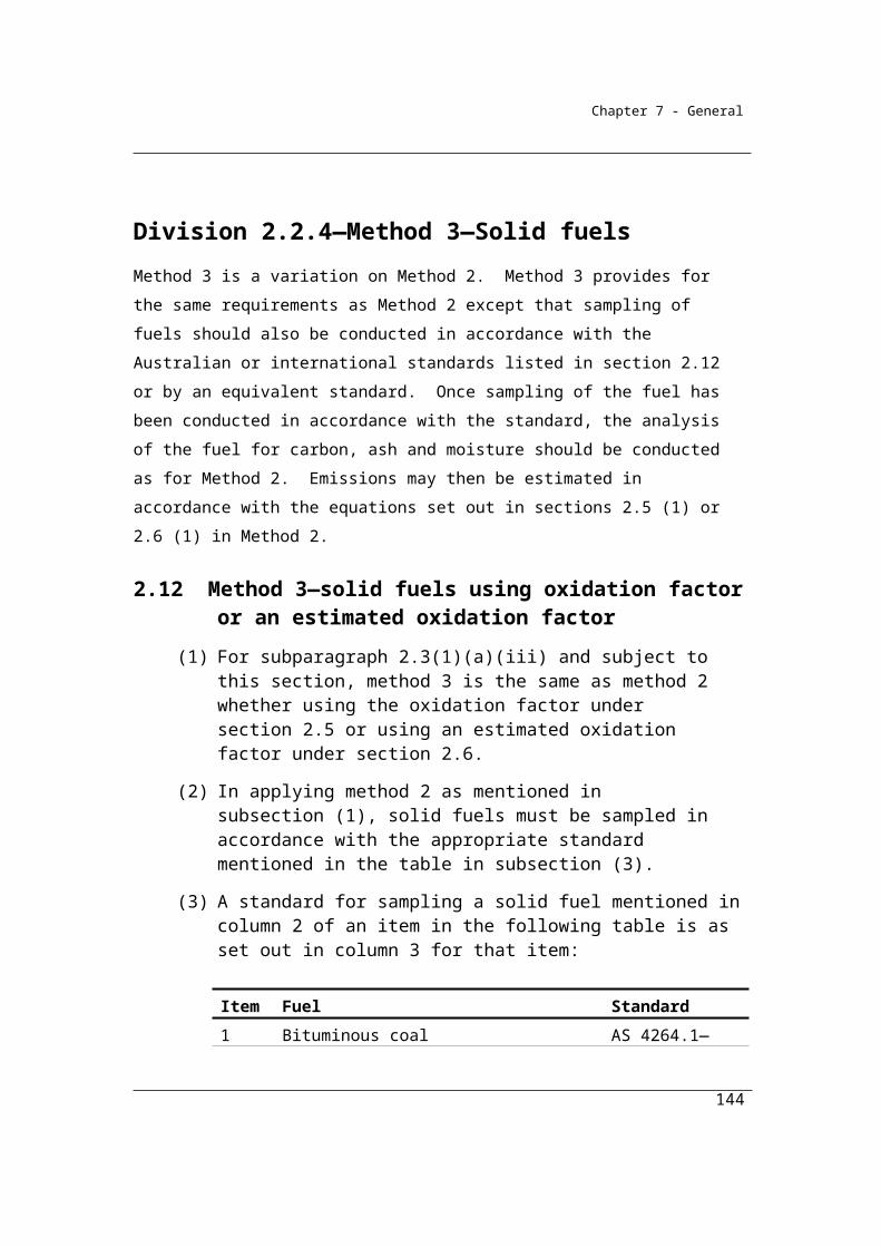
Chapter 7 - General
(4) If the measuring equipment uses any other type of flow device, the maximum uncertainty of flow measurement must not be greater than ±1.5%.
(5) All flow devices that are used by gas measuring equipment in a category specified in column 2 of an item in the table in section 2.31 must, wherever possible, be calibrated for pressure, differential pressure and temperature:
(a) in accordance with the requirements specified, for the item, in column 4 of the table; and
(b) taking into account the effects of static pressure and ambient temperature.
2.36 Flow computers—requirements
For paragraph 2.34(b), the requirement is that the flow computer that is used by the equipment for measuring purposes must record:
(a) the instantaneous values for all primary measurement inputs; and(b) the following outputs:
(i) instantaneous corrected volumetric flow;(ii) cumulative corrected volumetric flow;
(iii) for turbine and positive displacement metering systems—instantaneous uncorrected volumetric flow;
(iv) for turbine and positive displacement metering systems—cumulative uncorrected volumetric flow;
(v) super-compressibility factor.
2.37 Gas chromatographs—requirements
For paragraph 2.34(c), the requirements are that gas chromatographs used by the measuring equipment must:
(a) be factory tested and calibrated using a measurement standard:(i) produced by gravimetric methods; and
(ii) that uses Australian legal units of measurement; and(b) perform gas composition analysis with an accuracy of:
(i) ±0.15% for use in calculation of gross calorific value; and(ii) ±0.25% for calculation of relative density; and
(c) include a mechanism for re-calibration against a certified reference gas.
144

Chapter 7 - General
2.38 Simplified consumption measurements—criterion BBB
(1) For paragraph 2.29(4)(b), criterion BBB is the estimation of gaseous fuel in accordance with industry practice if the measuring equipment used to estimate consumption of the fuel does not meet the requirements of criterion AAA.
(2) For sources of landfill gas captured for the purpose of combustion for the production of electricity:
(a) the energy content of the captured landfill gas may be estimated:(i) if the manufacturer’s specification for the internal combustion
engine used to produce the electricity specifies an electrical efficiency factor—by using that factor; or
(ii) if the manufacturer’s specification for the internal combustion engine used to produce the electricity does not specify an electrical efficiency factor—by assuming that measured electricity dispatched for sale (sent out generation) represents 36% of the energy content of all fuel used to produce electricity; and
(b) the quantity of landfill gas captured in cubic metres may be derived from the energy content of the relevant gas set out in Part 2 of Schedule 1.
145

Chapter 7 - General
Part 2.4—Emissions released from the combustion of liquid fuels
Division 2.4.1—Preliminary
2.39 Application
This Part applies to emissions released from:(a) the combustion of petroleum based oil (other than petroleum based
oil used as fuel) or petroleum based grease, in relation to a separate instance of a source, if the total amount of oil and grease combusted in relation to the separate instance of the source is more than 5 kilolitres; and
(b) for a liquid fuel not of the kind mentioned in paragraph (a)—the combustion of liquid fuel in relation to a separate instance of a source, if the total amount of liquid fuel combusted in relation to the separate instance of the source is more than 1 kilolitre.
2.39A Definition of petroleum based oils for Part 2.4
In this Part:
petroleum based oils means petroleum based oils (other than petroleum based oils used as fuel).
Subdivision 2.4.1.1—Liquid fuels—other than petroleum based oils and greases
2.40 Available methods
(1) Subject to section 1.18, for estimating emissions released from the combustion of a liquid fuel, other than petroleum based oils and petroleum based greases, consumed from the operation of a facility during a year:
(a) one of the following methods must be used for estimating emissions of carbon dioxide:(i) method 1 under section 2.41;
(ii) method 2 under section 2.42;(iii) method 3 under section 2.47;(iv) method 4 under Part 1.3; and
146
Chapter 7 - General
(b) one of the following methods must be used for estimating emissions of methane and nitrous oxide:(i) method 1 under section 2.41;
(ii) method 2 under section 2.48.
(2) Under paragraph (1)(b), the same method must be used for estimating emissions of methane and nitrous oxide.
(3) However, for incidental emissions another method may be used that is consistent with the principles in section 1.13.Note: The combustion of liquid fuels releases emissions of carbon dioxide, methane
and nitrous oxide. Method 1 may be used to estimate emissions of each of these gases. There is no method 3 or 4 for emissions of methane or nitrous oxide.
Summary of available Methods by emissions of gas type (j)
CO2 CH4 N2O
Method 1 Section 2.41 Section 2.41 Section 2.41
Method 2 Sections 2.42 Section 2.48 Section 2.48
Method 3 Section 2.47
Method 4 Part 1.3
Subdivision 2.4.1.2—Liquid fuels—petroleum based oils and greases
2.40A Available methods
(1) Subject to section 1.18, for estimating emissions of carbon dioxide released from the consumption, as lubricants, of petroleum based oils or petroleum based greases, consumed from the operation of a facility during a year, one of the following methods must be used:
(a) method 1 under section 2.48A;(b) method 2 under section 2.48B; (c) method 3 under section 2.48C.
(2) However, for incidental emissions, another method may be used that is consistent with the principles in section 1.13.
147
Chapter 7 - General
Note: The consumption of petroleum based oils and greases, as lubricants, releases emissions of carbon dioxide. Emissions of methane and nitrous oxide are not estimated directly for this fuel type.
148

Chapter 7 - General
Division 2.4.2—Method 1—emissions of carbon dioxide, methane and nitrous oxide from liquid fuels other than petroleum based oils or greases
As for solid and gaseous fuels, Method 1 is derived from the National Greenhouse Accounts national methodology as published in the National Inventory Report. Emissions are estimated for individual fuel types by multiplying a (physical) quantity of fuel combusted by a fuel-specific energy content factor and a fuel-specific emission factor for each relevant greenhouse gas (in this case, carbon dioxide, methane and nitrous oxide).
The list of liquid fuels for which emissions must be calculated is given in Appendix A (taken from Schedule 1 of the National Greenhouse and Energy Reporting Regulations 2008).
Energy content and emission factors required for the estimation of emissions using this approach are given below. These factors are intended to be default factors – to be used in the absence of better information.
Once selected the energy content factor (ECi) for a particular fuel must be applied to all calculations of energy emissions from that fuel for a facility in the reporting year.
The emission factors listed have been estimated using the Australian Greenhouse Emissions Information System (AGEIS) operated by the Department on the Environment. Consequently, they are determined simultaneously with the production of Australia’s National Greenhouse Accounts ensuring that Reporter inventories are consistent with those national accounts.
Equipment specific factors for methane and nitrous oxide are provided for transport fleets. It is intended that the methane and nitrous oxide factors applicable to particular transport fleet should be utilised in the estimation of emissions for the fuel combusted for those fleets. No transport factors are provided for vehicles not registered for road use. Stationary energy factors for individual fuel types should be used in these cases.
149
Chapter 7 - General
2.41 Method 1—emissions of carbon dioxide, methane and nitrous oxide
(1) For subparagraphs 2.40(1)(a)(i) and (b)(i), method 1 for estimating emissions of carbon dioxide, methane and nitrous oxide is:
i i ijoxecij
Q C EFE =
1 000
where:
Eij is the emissions of gas type (j), being carbon dioxide, methane or nitrous oxide, released from the combustion of fuel type (i) from the operation of the facility during the year measured in CO2-e tonnes.
Qi is the quantity of fuel type (i) combusted from the operation of the facility for:
(a) stationary energy purposes; and(b) transport energy purposes;
during the year measured in kilolitres and estimated under Division 2.4.6.
ECi is the energy content factor of fuel type (i) estimated under section 6.5.
EFijoxec is the emission factor for each gas type (j) released from the operation of the facility during the year (which includes the effect of an oxidation factor) measured in kilograms CO2-e per gigajoule of fuel type (i) according to source as mentioned in:
(a) for stationary energy purposes—Part 3 of Schedule 1; and(b) for transport energy purposes—Division 4.1 of Schedule 1.
(2) In this section:
stationary energy purposes means purposes for which fuel is combusted that do not involve transport energy purposes.
transport energy purposes includes purposes for which fuel is combusted that consist of any of the following:
(a) transport by vehicles registered for road use;(b) rail transport;(c) marine navigation;(d) air transport.
Note: The combustion of liquid fuels produces emissions of carbon dioxide, methane and nitrous oxide.
150

Chapter 7 - General
Table 2.4.2A Emission and energy content factors — liquid fuels and certain petroleum-based products for stationary energy purposes
Item Fuel combusted Energy content factor
(GJ/kL unless otherwise indicated)
Emission factorkg CO2-e/GJ
(RELEVANT OXIDATION FACTORS INCORPORATED)
CO2 CH4 N2O
31 Petroleum based oils (other than petroleum based oil used as fuel)
38.8 13.9 0.0 0.0
32 Petroleum based greases 38.8 3.5 0.0 0.033 Crude oil including crude oil
condensates45.3 GJ/t 69.6 0.1 0.2
34 Other natural gas liquids 46.5 GJ/t 61.0 0.1 0.235 Gasoline (other than for use as
fuel in an aircraft)34.2 67.4 0.2 0.2
36 Gasoline for use as fuel in an aircraft
33.1 67.0 0.2 0.2
37 Kerosene (other than for use as fuel in an aircraft)
37.5 68.9 0.0 0.2
38 Kerosene for use as fuel in an aircraft
36.8 69.6 0.02 0.2
39 Heating oil 37.3 69.5 0.03 0.240 Diesel oil 38.6 69.9 0.1 0.241 Fuel oil 39.7 73.6 0.04 0.242 Liquefied aromatic hydrocarbons 34.4 69.7 0.02 0.243 Solvents if mineral turpentine or
white spirits34.4 69.7 0.02 0.2
44 Liquefied petroleum gas 25.7 60.2 0.2 0.245 Naphtha 31.4 69.8 0.00 0.0146 Petroleum coke 34.2 GJ/t 92.6 0.07 0.247 Refinery gas and liquids 42.9 GJ/t 54.7 0.02 0.048 Refinery coke 34.2 GJ/t 92.6 0.07 0.2
151

Chapter 7 - General
Item Fuel combusted Energy content factor
(GJ/kL unless otherwise indicated)
Emission factorkg CO2-e/GJ
(RELEVANT OXIDATION FACTORS INCORPORATED)
CO2 CH4 N2O
49 Petroleum based products other than:(a) petroleum based oils and
petroleum based greases mentioned in items 31 and 32; and
(b) the petroleum based products mentioned in items 33 to 48.
34.4 69.8 0.0 0.2
50 Biodiesel 34.6 0.0 0.07 0.251 Ethanol for use as a fuel in an
internal combustion engine23.4 0.0 0.07 0.2
52 Biofuels other than those mentioned in items 50 and 51
23.4 0.0 0.07 0.2
Notes on the sources of the factors listed above can be found at Appendix 2A.
Note: The National Greenhouse and Energy reporting Regulations 2008 makes reference to Petroleum Coke as being a solid substance under Section 1.03. However, for the purposes of estimating emissions under the NGER (Measurement) Determination 2008, Petroleum coke is classified in Part 3 of Schedule 1 under "Liquid and other certain petroleum-based products". This classification is consistent with IPCC Guidelines and the International Energy Agency fuel classification system.
152
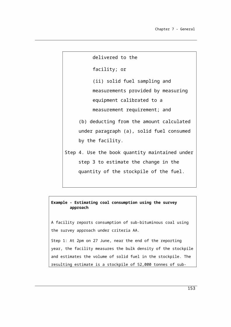
Chapter 7 - General
Table 2.4.2B Emissions and energy content factors — fuels for transport energy purposes
Item Fuel combusted Energy content factor
(GJ/kL unless otherwise indicated)
Emission factorkg CO2-e/GJ
(RELEVANT OXIDATION FACTORS
INCORPORATED)
CO2 CH4 N2O
53 Gasoline (other than for use as fuel in an aircraft)
34.2 67.4 0.5 1.8
54 Diesel oil 38.6 69.9 0.1 0.555 Gasoline for use as fuel in an
aircraft33.1 67.0 0.05 0.7
56 Kerosene for use as fuel in an aircraft
36.8 69.6 0.01 0.6
57 Fuel oil 39.7 73.6 0.07 0.658 Liquefied petroleum gas 26.2 60.2 0.6 0.759 Biodiesel 34.6 0.0 0.7 1.960 Ethanol for use as fuel in an
internal combustion engine23.4 0.0 0.7 1.9
61 Biofuels other than those mentioned in items 59 and 60
23.4 0.0 0.7 1.9
Notes on the sources of the factors listed above can be found at Appendix 2A.
153
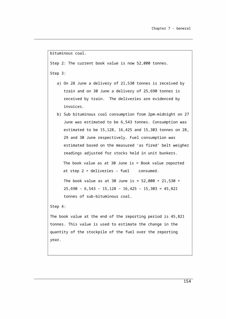
Chapter 7 - General
Division 2.4.3—Method 2—emissions of carbon dioxide from liquid fuels other than petroleum based oils or greases
As for solid and gaseous fuels, Method 1 applies national average factors to the estimation of emissions. More accurate estimates of emissions at a facility level may be obtained by sampling and analysing fuels for qualities that affect emission levels when the fuel is combusted. These qualities include the fuel’s carbon content which may vary from fuel to fuel, albeit reasonably marginally for standard commercial fuels.
The list of liquid fuels for which emissions must be calculated is given in Table 2.4.3 (taken from Schedule 1 of the National Greenhouse and Energy Reporting Regulations 2008).
Subdivision 2.4.3.1—Method 2—emissions of carbon dioxide from liquid fuels other than petroleum based oils or greases
2.42 Method 2—emissions of carbon dioxide from the combustion of liquid fuels
(1) For subparagraph 2.40(1)(a)(ii), method 2 for estimating emissions of carbon dioxide is:
2 2
2i ico co
i ico oxec RCCSQ × EC × EF
= - γ1 000
E
where:
EiCO2 is the emissions of carbon dioxide released from the combustion of fuel type (i) from the operation of the facility during the year measured in CO2-e tonnes.
Qi is the quantity of fuel type (i) combusted from the operation of the facility during the year measured in kilolitres .
ECi is the energy content factor of fuel type (i) estimated under section 6.5.
EFiCO2oxec is the carbon dioxide emission factor for fuel type (i) measured in kilograms of CO2-e per gigajoule.
154
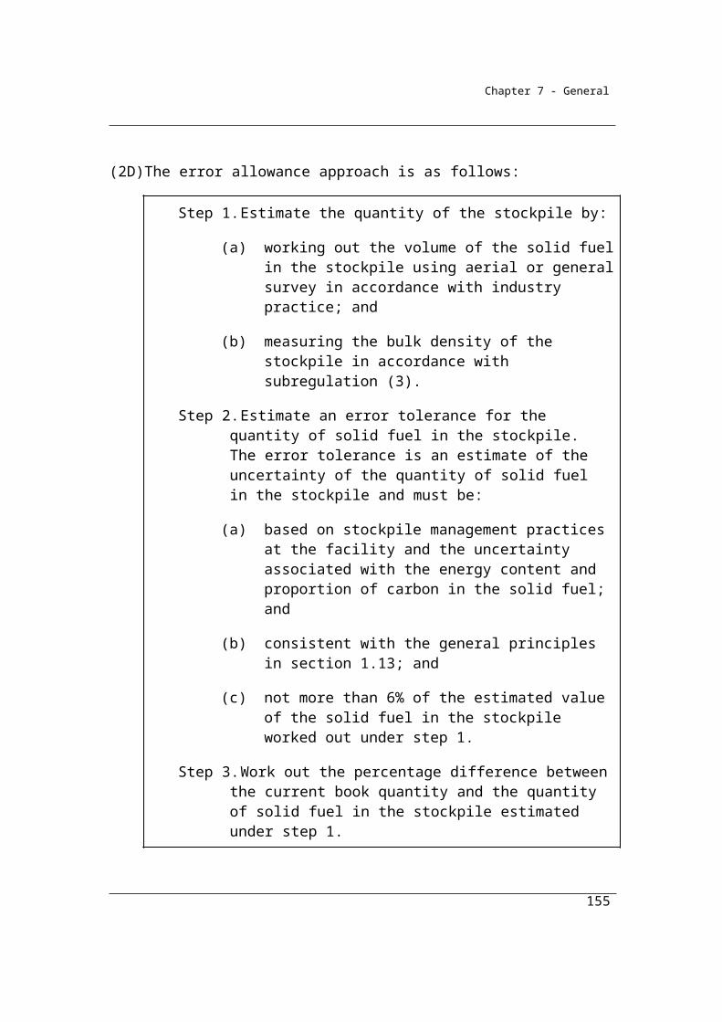
Chapter 7 - General
γ is the factor 1.861 × 10⁻³ for converting a quantity of carbon dioxide from cubic metres at standard conditions of pressure and temperature to CO2-e tonnes.
RCCSCO2 is carbon dioxide captured for permanent storage measured in cubic metres in accordance with Division 1.2.3.
(2) Method 2 requires liquid fuels to be sampled and analysed in accordance with the requirements in sections 2.44, 2.45 and 2.46.
2.43 Calculation of emission factors from combustion of liquid fuel
(1) For section 2.42, the emission factor EFi,CO2,ox,ec from the combustion of fuel type (i) must allow for oxidation effects and must first estimate EFi,co2,ox,kg in accordance with the following formula:
i, co2,ox,kg i aCEF = OF 3.664
100
where:
Ca is the carbon in the fuel expressed as a percentage of the mass of the fuel as received, as sampled, or as combusted, as the case may be.
OFi is the oxidation factor 1.0 applicable to liquid fuels.Note: 3.664 converts tonnes of carbon to tonnes of carbon dioxide.
(2) The emission factor derived from the calculation in subsection (1), must be expressed in kilograms of carbon dioxide per gigajoule calculated using the following formula:
ii, co2,ox,ec i, co2,ox,kg
i
ECEF = EF C
where:
ECi is the energy content factor of fuel type (i) estimated under subsection 2.42(1).
Ci is the density of the fuel expressed in kilograms of fuel per thousand litres as obtained using a Standard set out in section 2.45.
Subdivision 2.4.3.2—Sampling and analysis
Under Method 2, representative and unbiased samples of fuels consumed must be obtained for analysis. Analysis of the fuels for carbon, energy, ash or moisture
155
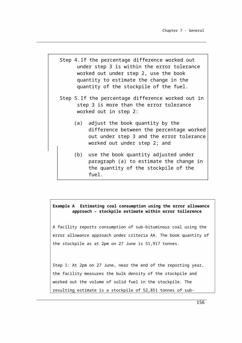
Chapter 7 - General
content must be done in accordance with listed Australian or international standards. A listing of applicable standards is given in Section 2.45. Examples of equivalent standards include those produced by AS, NZ, ASTM, ISO and CEN standards organisations. The standards must be in force on the date stated in section 1.9.
Unlike solid and gaseous fuels, standards for analysis have not been listed for a number of fuel types, reflecting the apparent absence of such standards particularly for volatile fuels. It is considered that for many liquid fuels that the use of Method 2 facility-specific emission factors would be likely to bring only marginal benefits in any case.
A NATA (National Association of Testing Authorities) accredited laboratory or similar laboratory complying with ISO 17025 should be used to conduct the analysis.
Minimum frequencies of analysis are also provided for in section 2.46.
2.44 General requirements for sampling under method 2
(1) A sample of the liquid fuel must be derived from a composite of amounts of the liquid fuel.
(2) The samples must be collected on enough occasions to produce a representative sample.
(3) The samples must also be free of bias so that any estimates are neither over nor under estimates of the true value.
(4) Bias must be tested in accordance with an appropriate standard (if any).
(5) The value obtained from the samples must only be used for the delivery period or consignment of the liquid fuel for which it was intended to be representative.
2.45 Standards for analysing samples of liquid fuels
(1) Samples of liquid fuel of a type mentioned in column 2 of an item in the following table must be analysed in accordance with a standard (if any) mentioned in:
(a) for energy content analysis—column 3 for that item; and(b) for carbon analysis—column 4 for that item; and(c) density analysis—column 5 for that item.
156
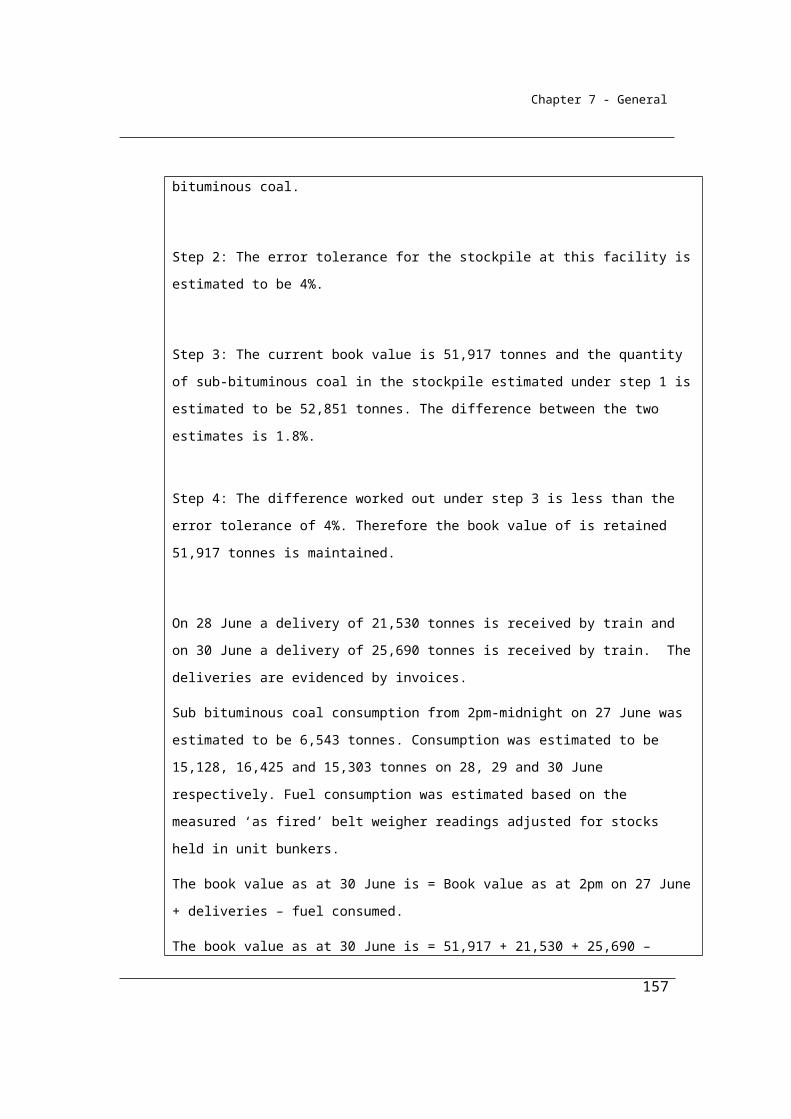
Chapter 7 - General
Item Fuel Energy Content
Carbon Density
1 Petroleum based oils (other than petroleum based oils used as fuel)
N/A ASTM D 5291-02 (2007)
ASTM D 1298 – 99 (2005)
2 Petroleum based greases
N/A ASTM D 5291-02 (2007)
ASTM D 1298 – 99 (2005)
3 Crude oil including crude oil condensates
ASTM D 240-02 (2007)ASTM D 4809-06
ASTM D 5291-02 (2007)
ASTM D 1298 – 99 (2005) ASTM D 5002 – 99 (2005)
4 Other natural gas liquids
N/A N/A ASTM D 1298 – 99 (2005)
5 Gasoline (other than for use as fuel in an aircraft)
ASTM D 240-02 (2007)ASTM D 4809-06
N/A ASTM D 1298 – 99 (2005)
6 Gasoline for use as fuel in an aircraft
ASTM D 240-02 (2007)ASTM D 4809-06
N/A ASTM D 1298 – 99 (2005)
7 Kerosene (other than for use as fuel in an aircraft)
ASTM D 240-02 (2007)ASTM D 4809-06
N/A ASTM D 1298 – 99 (2005) ASTM D 4052 – 96 (2002) e1
8 Kerosene for use as fuel in an aircraft
ASTM D 240-02 (2007)ASTM D 4809-06
N/A ASTM D 1298 – 99 (2005) ASTM D 4052 – 96 (2002) e1
9 Heating oil ASTM D 240-02 (2007)ASTM D 4809-06
ASTM D 5291-02 (2007)
ASTM D 1298 – 99 (2005)
10 Diesel oil ASTM D ASTM D ASTM D
157
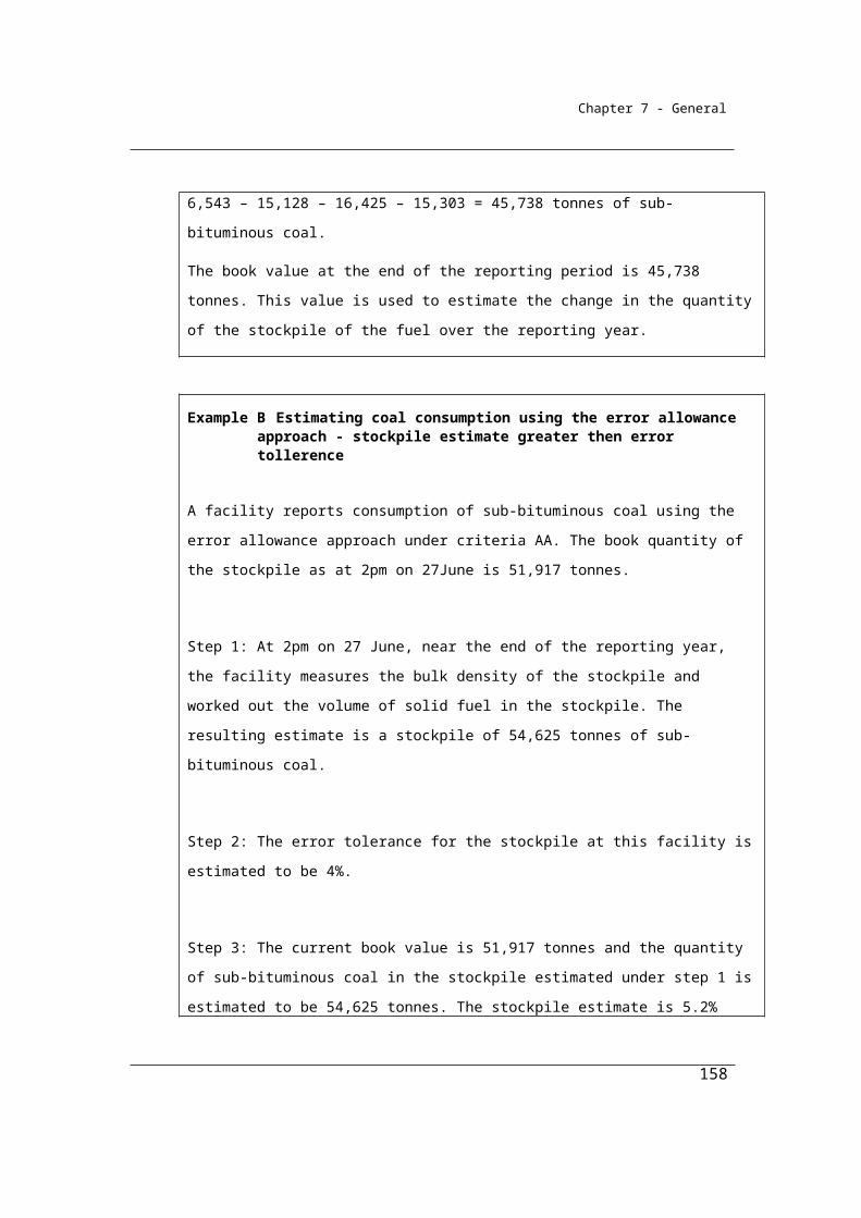
Chapter 7 - General
Item Fuel Energy Content
Carbon Density
240-02 (2007)ASTM D 4809-06
5291-02 (2007) 1298 – 99 (2005)
11 Fuel oil ASTM D 240-02 (2007)ASTM D 4809-06
ASTM D 5291-02 (2007)
ASTM D 1298 – 99 (2005)
12 Liquefied aromatic hydrocarbons
N/A N/A ASTM D 1298 – 99 (2005)
13 Solvents if mineral turpentine or white spirits
N/A N/A N/A
14 Liquefied Petroleum Gas
N/A ISO 7941:1988 ISO 6578:1991ISO 8973:1997ASTM D 1657 – 02
15 Naphtha N/A N/A N/A16 Petroleum coke N/A N/A N/A17 Refinery gas and
liquidsN/A N/A N/A
18 Refinery coke N/A N/A N/A19 Petroleum based
products other than:(a) petroleum
based oils and petroleum based greases mentioned in items 1and 2
(b) the petroleum based products mentioned in items 3 to 18
N/A N/A N/A
20 Biodiesel N/A N/A N/A21 Ethanol for use as
a fuel in an N/A N/A N/A
158

Chapter 7 - General
Item Fuel Energy Content
Carbon Density
internal combustion engine
22 Biofuels other than those mentioned in items 20 and 21
N/A N/A N/A
(2) A liquid fuel of a type mentioned in column 2 of an item in the table in subsection (1) may also be analysed for energy content, carbon and density in accordance with a standard that is equivalent to a standard mentioned in columns 3, 4 and 5 for that item.
(3) Analysis must be undertaken by an accredited laboratory or by a laboratory that meets requirements equivalent to those in AS ISO/IEC 17025:2005.
2.46 Frequency of analysis
Liquid fuel of a type mentioned in column 2 of an item in the following table must be analysed for the parameter mentioned in column 3 for that item at least at the frequency mentioned in column 4 for that item.
Item Fuel Parameter Frequency1 All types of liquid
fuelCarbon Quarterly or by delivery of
the fuel2 All types of liquid
fuelEnergy Quarterly or by delivery of
the fuel
159
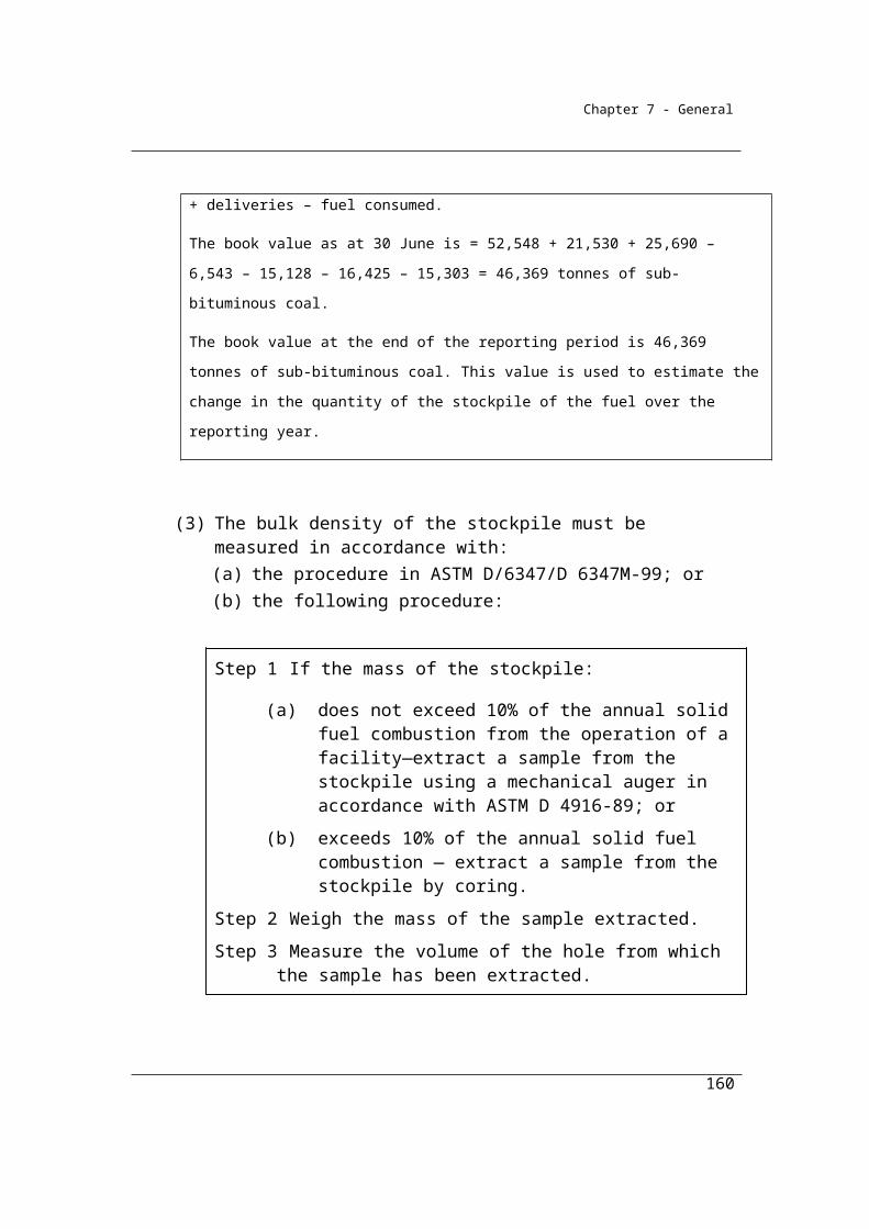
Chapter 7 - General
Division 2.4.4—Method 3—emissions of carbon dioxide from liquid fuels other than petroleum based oils or greases
As for solid and gaseous fuels, Method 3 is a variation on Method 2. Method 3 provides for the same requirements of Method 2 except that sampling of fuels should also be conducted in accordance with listed Australian or international standards in section 2.47 or by an equivalent standard. Once sampling of the fuel has been conducted in accordance with the standard, the analysis of the fuel for carbon and other factors should be conducted as for Method 2. Emissions may then be estimated in accordance with Method 2.
2.47 Method 3—emissions of carbon dioxide from the combustion of liquid fuels
(1) For subparagraph 2.40(1)(a)(iii) and subject to this section, method 3 for estimating emissions of carbon dioxide is the same as method 2 under section 2.42.
(2) In applying method 2 under section 2.42, liquid fuels must be sampled in accordance with a standard specified in the table in subsection (3).
(3) A standard for sampling a liquid fuel of a type mentioned in column 2 of an item in the following table is specified in column 3 for that item.
item Liquid Fuel Standard
1 Petroleum based oils (other than petroleum based oils used as fuel)
ISO 3170:2004ISO 3171:1988ASTM D 4057 – 06
2 Petroleum based greases
3 Crude oil including crude oil condensates
ISO 3170:2004ISO 3171:1988ASTM D 4057 – 06ASTM D 4177 – 95 (2005)
4 Other natural gas liquids ASTM D1265 – 055 Gasoline (other than for use as
fuel in an aircraft)ISO 3170:2004ISO 3171:1988ASTM D 4057 – 06
160
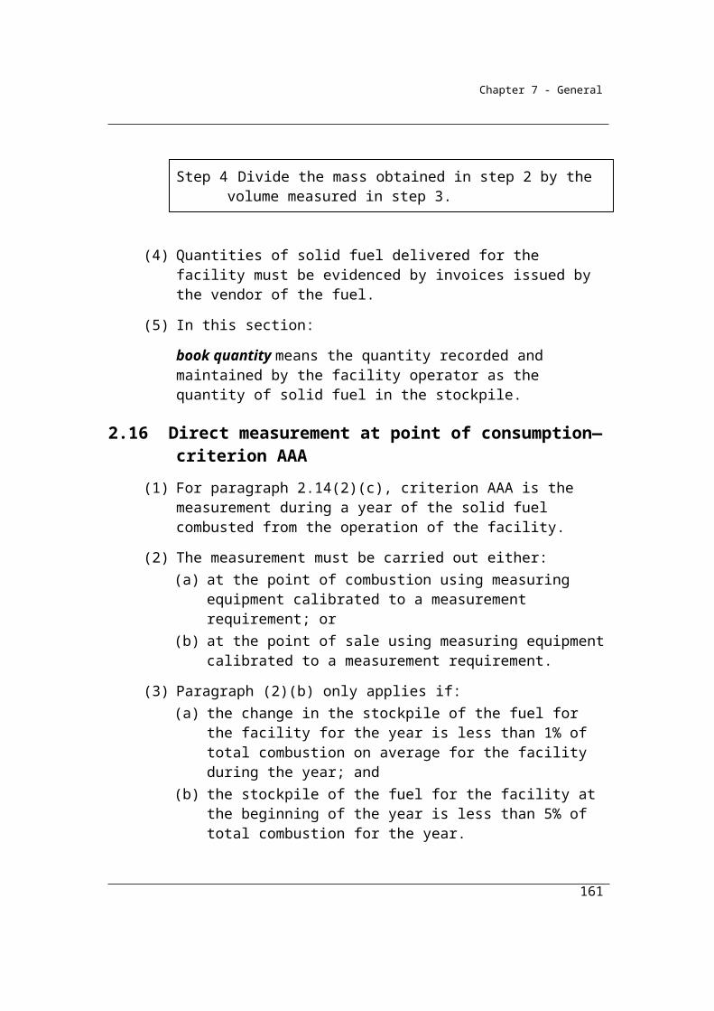
Chapter 7 - General
item Liquid Fuel Standard
ASTM D 4177 – 95 (2005)6 Gasoline for use as fuel in an
aircraftISO 3170:2004ISO 3171:1988ASTM D 4057 – 06ASTM D 4177 – 95 (2005)
7 Kerosene (other than for use as fuel in an aircraft)
ISO 3170:2004ISO 3171:1988ASTM D 4057 – 06ASTM D 4177 – 95 (2005)
8 Kerosene for use as fuel in an aircraft
ISO 3170:2004ISO 3171:1988ASTM D 4057 – 06ASTM D 4177 – 95 (2005)
9 Heating oil ISO 3170:2004ISO 3171:1988ASTM D 4057 – 06ASTM D 4177 – 95 (2005)
10 Diesel oil ISO 3170:2004ISO 3171:1988ASTM D 4057 – 06ASTM D 4177 – 95 (2005)
11 Fuel oil ISO 3170:2004ISO 3171:1988ASTM D 4057 – 06ASTM D 4177 – 95 (2005)
12 Liquefied aromatic hydrocarbons
ASTM D 4057 – 06
13 Solvents if mineral turpentine or white spirits
ASTM D 4057 – 06
14 Liquefied Petroleum Gas ASTM D1265 – 05)ISO 4257:2001
15 Naphtha ISO 3170:2004ISO 3171:1988ASTM D 4057 – 06
16 Petroleum coke ASTM D 4057 – 0617 Refinery gas and liquids ASTM D 4057 – 06
161
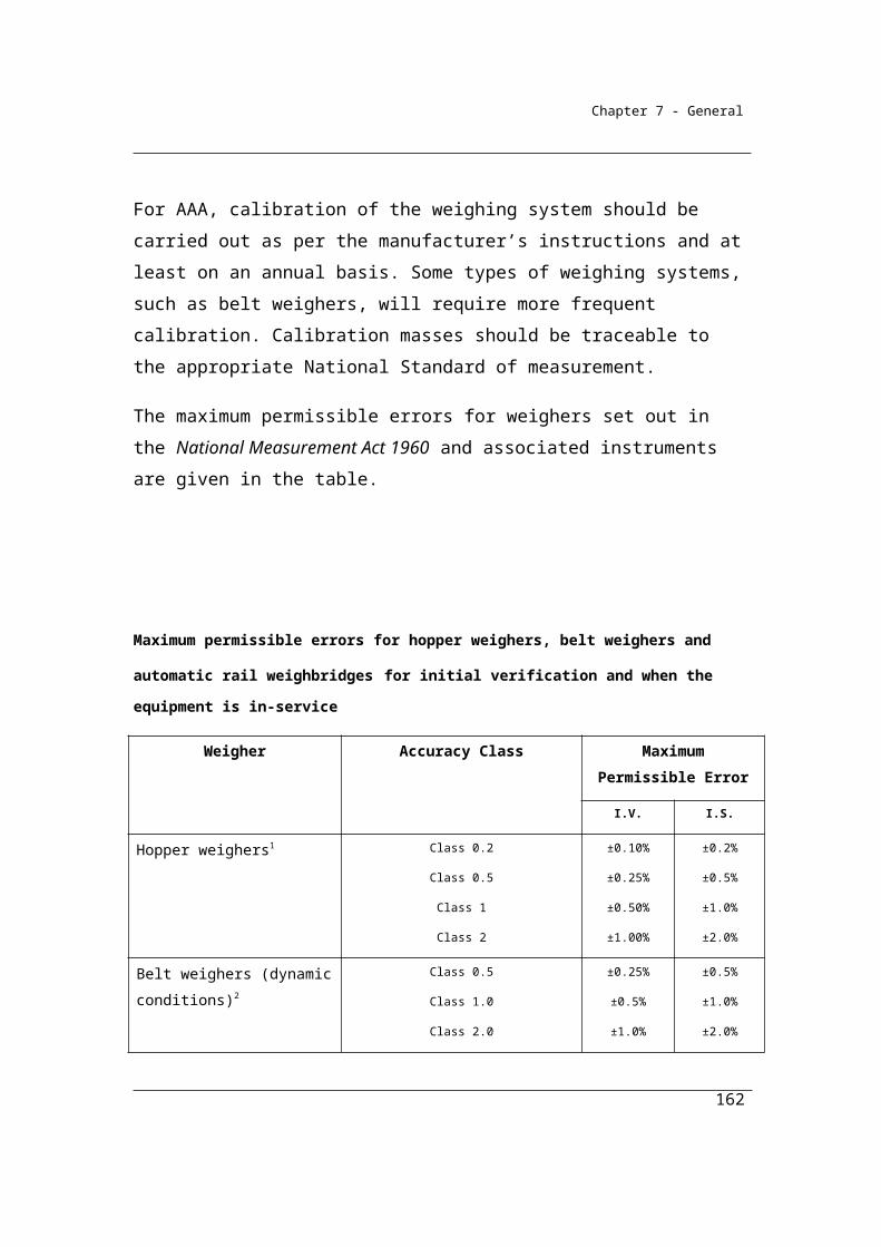
Chapter 7 - General
item Liquid Fuel Standard
18 Refinery coke ASTM D 4057 – 0619 Petroleum based products other
than:(a) petroleum based oils and
petroleum based greases mentioned in items 1 and 2; and
(b) the petroleum based products mentioned in items 3 to 18
ISO 3170:2004ISO 3171:1988ASTM D 4057 – 06
20 Biodiesel ISO 3170:2004ISO 3171:1988ASTM D 4057 – 06ASTM D 4177 – 95 (2005)
21 Ethanol for use as a fuel in an internal combustion engine
ASTM D 4057 – 06
22 Biofuels other than those mentioned in items 20 and 21
ISO 3170:2004ISO 3171:1988ASTM D 4057 – 06ASTM D 4177 – 95 (2005)
(4) A liquid fuel may also be sampled in accordance with a standard that is equivalent to a standard set out in the table in subsection (3) in relation to that liquid fuel.
162
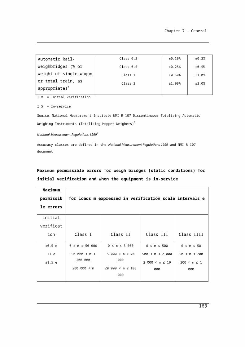
Chapter 7 - General
Division 2.4.5—Method 2—emissions of methane and nitrous oxide from liquid fuels other than petroleum based oils or greases
Method 2 for the estimation of methane and nitrous oxide emissions from the combustion of liquid fuels is very similar to Method 1 - however the Reporter uses an equipment-specific emission factor set out in Schedule 1 of the Determination. This approach is only available for post-2004 vehicles and certain trucks with specified engine designs.
No sampling and analysis of fuels are required for this Method 2 for non-carbon dioxide emissions. This is because the emissions of methane and nitrous oxide depend, in general, on combustion conditions and the equipment used to combust the fuel. In contrast, the carbon dioxide emissions depend on the chemical qualities of the fuels themselves which can only be ascertained by analysis.
2.48 Method 2—emissions of methane and nitrous oxide from the combustion of liquid fuels
(1) For subparagraph 2.40(1)(b)(ii) and subject to subsection (2), method 2 for estimating emissions of methane and nitrous oxide is the same as method 1 under section 2.41.
(2) In applying method 1 in section 2.41, the emission factor EFijoxec is taken to be the emission factor set out in:
(a) for combustion of fuel by vehicles manufactured after 2004—columns 5 and 6 of the table in Division 4.2 of Part 4 of Schedule 1; and
(b) for combustion of fuel by trucks that meet the design standards mentioned in column 3 of the table in Division 4.3 of Part 4 of Schedule 1—columns 6 and 7 of the table in that Division.
163
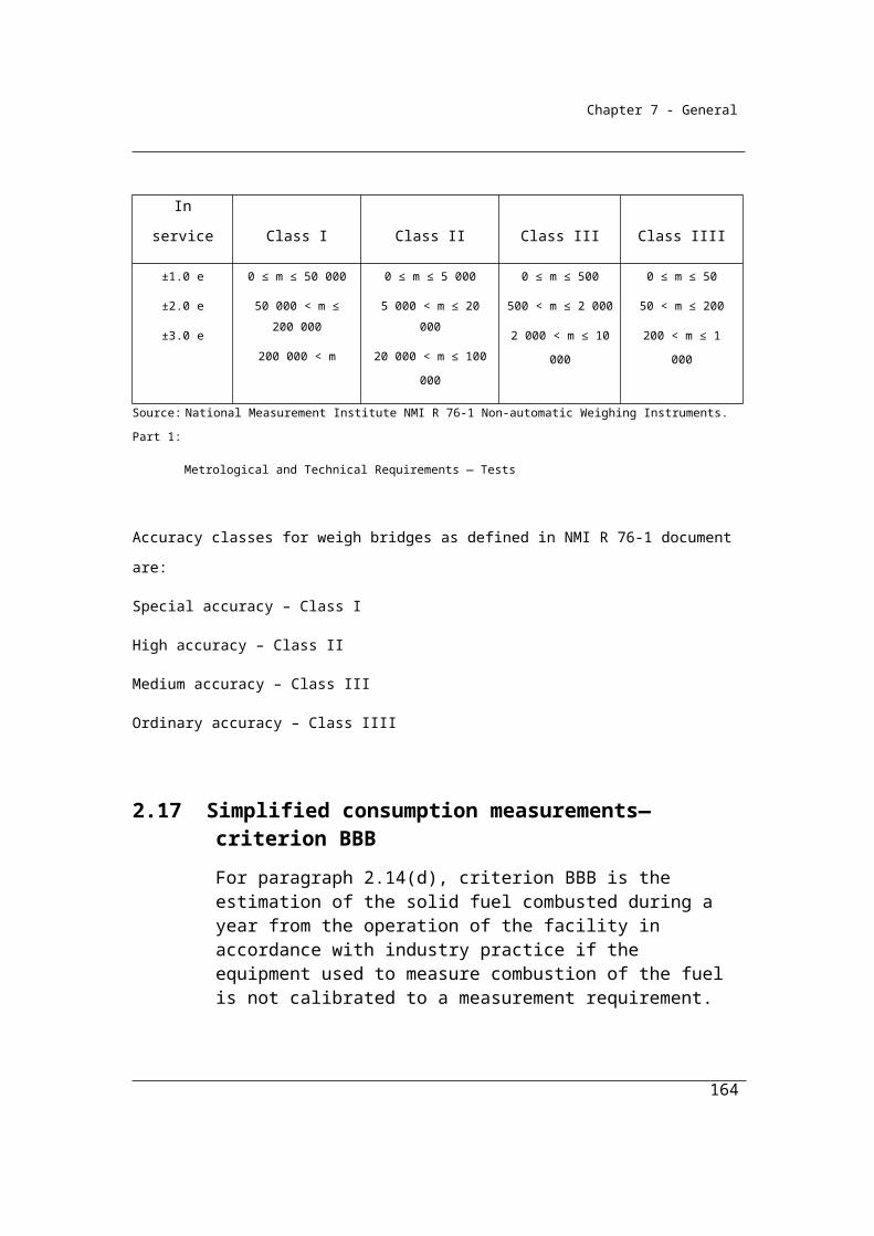
Chapter 7 - General
Table 2.4.5A Fuel combustion — liquid fuels for transport energy purposes for post-2004 vehicles
Item Fuel combusted Energy content factor
GJ/kL
Emission factorkg CO2-e/GJ
(RELEVANT OXIDATION FACTORS INCORPORATED)
CO2 CH4 N2O
64 Gasoline (other than for use as fuel in an aircraft)
34.2 67.4 0.02 0.2
65 Diesel oil 38.6 69.9 0.01 0.666 Liquefied petroleum gas 26.2 60.2 0.4 0.367 Ethanol for use as fuel in an
internal combustion engine23.4 0.0 0.2 0.2
Notes on the sources of the factors listed above can be found at Appendix 2A.
Table 2.4.5B Fuel combustion — liquid fuels for transport energy purposes for certain trucks
Item Fuel type Heavy vehicles design standard
Energy content factor
GJ/kL
Emission factorkg CO2-e/GJ
(RELEVANT OXIDATION FACTORS INCORPORATED)
CO2 CH4 N2O
68 Diesel oil Euro iv or higher
38.6 69.9 0.06 0.5
69 Diesel oil Euro iii 38.6 69.9 0.1 0.5
164

Chapter 7 - General
Item Fuel type Heavy vehicles design standard
Energy content factor
GJ/kL
Emission factorkg CO2-e/GJ
(RELEVANT OXIDATION FACTORS INCORPORATED)
CO2 CH4 N2O
70 Diesel oil Euro i 38.6 69.9 0.2 0.5
Notes on the sources of the factors listed above can be found at Appendix 2A.
Example
A company consumes 35 000 kL (kilolitres) of diesel oil: 25 000 kL for transport purposes (with a post-2004 vehicle fleet) and 10 000 kL for stationary energy purposes. The Reporter elects to use Method 1 (Division 2.4.2) for each of the three greenhouse emission gases (j) (carbon dioxide, methane and nitrous oxide) for the diesel consumed for stationary energy purposes and Method 2 for methane and nitrous oxide emissions from diesel consumed for transport by post 2004 vehicles. Emissions are estimated as follows:
where:
Eij is emissions of gas type (j) released from the combustion of fuel type (i) from the operation of the facility during the year measured in CO2-e tonnes.
Qi is the quantity of the fuel type (i) combusted from the operation of the facility during the year measured in tonnes and estimated under Division 2.4.6. In this case 25 000 kL of diesel is used for transport purposes and 10 000kL of diesel is for stationary energy purposes.
ECi is the energy content factor of fuel type (i) estimated under section 6.5
(a) for stationary energy purposes — column 3 of the table 2.4.2A (Part 3 of Schedule 1 of the Determination). In this case being 38.6 GJ/kL.
(b) for post-2004 vehicles — column 3 of table 2.4.5A (Division 4.2 of Part 4 of Schedule 1 of the Determination). In this case being 38.6 GJ/kL.
165
Chapter 7 - General
EFoxij is the emission factor for each gas type (j) released from the operation of the facility during the year (which includes the effect of a default oxidation factor) measured in kilograms CO2- e per gigajoule of the fuel type (i) according to source as mentioned in:
(a) for stationary energy purposes — columns 4-6 of the table 2.4.2A (Part 3 of Schedule 1 of the Determination); and
(b) for post-2004 vehicles — column 4-6 of table 2.4.5A (Division 4.2 of Part 4 of Schedule 1 of the Determination).
Therefore, emissions of greenhouse gases (carbon dioxide, methane and nitrous oxide) in tonnes of CO2-e are estimated as follows:
Combustion of diesel oil for stationary energy purposes (Method 1):
Emissions of carbon dioxide
= (10 000 x 38.6 x 69.9)/1 000
= 26, 981 t CO2-e
Emissions of methane
= (10 000 x 38.6 x 0.1)/1 000
= 39 t CO2-e
Emissions of nitrous oxide
= (10 000 x 38.6 x 0.2)/1 000
= 77 t CO2-e
Combustion of diesel oil for transport purposes for post-2004 vehicles:
Emissions of carbon dioxide
= (25 000 x 38.6 x 69.9)/1 000
= 67,454 t CO2-e
Emissions of methane (Method 2)
= (25 000 x 38.6 x 0.01)/1 000
166

Chapter 7 - General
= 10 t CO2-e
Emissions of nitrous oxide (Method 2)
= (25 000 x 38.6 x 0.5)/1 000
= 482.5 t CO2-e
167

Chapter 7 - General
Division 2.4.5A—Methods for estimating emissions of carbon dioxide from petroleum based oils or greases
This method applies to the consumption of petroleum based oils or greases (PBOGs) as lubricants or greases.
PBOGs that are consumed without combustion should be reported under section 2.68. Some scenarios to which section 2.68 of the Determination would apply include:
coating of metal products with petroleum-based oils for corrosion protection;
use of petroleum-based oils as hydraulic fluids (including brake fluids);
greases used in electric motor applications;
oils used in gearboxes;
use of petroleum-based oils as components of products such as oil-extended polymers or elastomers, paints, solvents or sprays;
use of oils in electrical equipment (e.g. transformer oil); and
use of oils as heat transfer fluids or working fluids in industrial applications.
Depending on the operating conditions of the facility and the number and complexity of consumption points, reporters may wish to use the flash point of the fuel to identify whether or not the PBOG could be combusted. The flash point is the lowest temperature at which a product can form a vapour/air mixture capable of combustion. It is a measurable and testable physical property of all petroleum-based products and is stated on the Material Safety Data Sheet of every PBOG product sold.
By comparing the maximum operating temperature that each PBOG is likely to be exposed, it is possible to show that a given PBOG is appropriately reported as consumed without combustion.
168
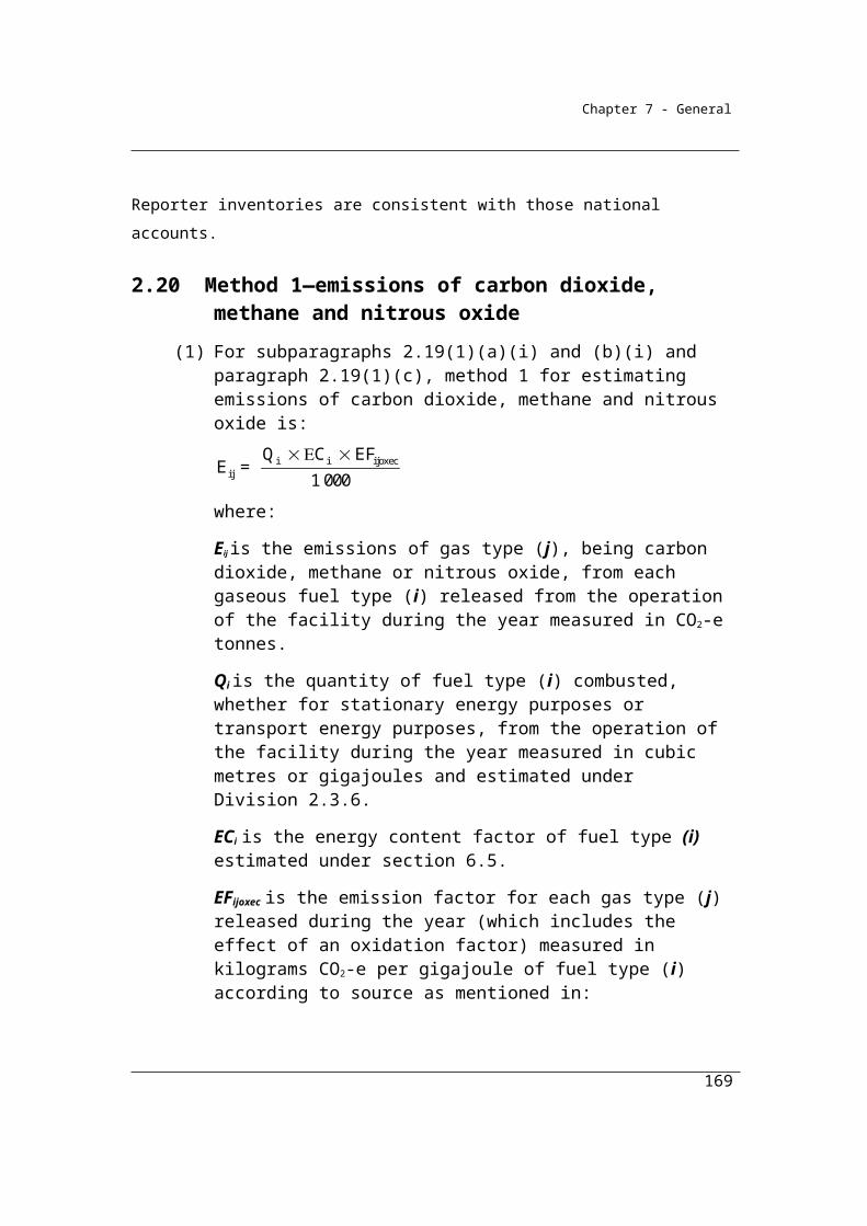
Chapter 7 - General
2.48A Method 1—estimating emissions of carbon dioxide using an estimated oxidation factor
(1) For paragraph 2.40A(1)(a), method 1 for estimating emissions of carbon dioxide from the consumption of petroleum based oils or petroleum based greases using an estimated oxidation factor is:
pogco2oxecpogco2 pog pogco2
EFE = Q EC
1 000
where:
Epogco2 is the emissions of carbon dioxide released from the consumption of petroleum based oils or petroleum based greases from the operation of the facility during the year measured in CO2-e tonnes.
Qpog is the quantity of petroleum based oils or petroleum based greases consumed from the operation of the facility, estimated in accordance with Division 2.4.6.
ECpogco2 is the energy content factor of petroleum based oils or petroleum based greases measured in gigajoules per kilolitre as mentioned in Part 3 of Schedule 1.
EFpogco2oxec has the meaning given in subsection (2).
(2) EFpogco2oxec is:(a) the emission factor for carbon dioxide released from the operation of
the facility during the year (which includes the effect of an oxidation factor) measured in kilograms CO2-e per gigajoule of the petroleum based oils or petroleum based greases as mentioned in Part 3 of Schedule 1; or
(b) to be estimated as follows:
pogco2oxec pog pogco2ecEF = OF EF
where:
OFpog is the estimated oxidation factor for petroleum based oils or petroleum based greases.
EFpogco2ec is 69.9.
(3) For OFpog in paragraph (2)(b), estimate as follows:
169
Chapter 7 - General
pog pogpog
pog
Q Oil Transferred OffsiteOF =
Q
where:
Qpog is the quantity of petroleum based oils or petroleum based greases consumed from the operation of the facility, estimated in accordance with Division 2.4.6.
Oil Transferred Offsitepog is the quantity of oils, derived from petroleum based oils or petroleum based greases, transferred outside the facility, and estimated in accordance with Division 2.4.6.
2.48B Method 2—estimating emissions of carbon dioxide using an estimated oxidation factor
For paragraph 2.40A(1)(b), method 2 is the same as method 1 but the emission factor EFpogco2ec must be determined in accordance with Division 2.4.3.
2.48C Method 3—estimating emissions of carbon dioxide using an estimated oxidation factor
For paragraph 2.40A(1)(c), method 3 is the same as method 1 but the emission factor EFpogco2ec must be determined in accordance with Division 2.4.4.
170
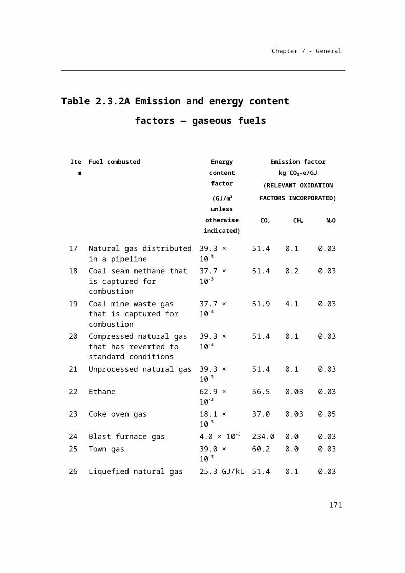
Chapter 7 - General
Division 2.4.6—Measurement of quantity of liquid fuels
2.49 Purpose of Division
This Division sets out how quantities of liquid fuels combusted from the operation of a facility are to be estimated for the purpose of working out the emissions released from the combustion of that fuel.
The quantity of consumption of each of the fuel types specified in the Regulations, Schedule 1, are to be estimated according to one of the criterion set out below.
The fuel types listed principally reflect the lists of fuels currently used by the Bureau of Resources and Energy Economics (BREE) to prepare Australia’s Energy Statistics and report, inter alia, on behalf of the Australian Government to the International Energy Agency.
Separate estimates of the quantities of each fuel type consumed for the purpose of making electricity; for use as reductants or feedstocks; for use in transport (excluding international bunker fuels) and other stationary energy are required.
The quantities of fuels consumed for transport should exclude those quantities consumed for international transport purposes, if any, to reflect international reporting requirements for the national inventory. It is intended that this may be achieved by excluding international bunker fuels as defined in National Greenhouse and Energy Reporting Regulations 2008, Regulation 1.03, and that the point of differentiation between domestic and international consumption will be identical to that provided by the Customs Act 1901 which is used also for excise and GST purposes.
Biogenic carbon fuels attract a zero carbon dioxide emission factor to ensure that the reporting system aligns with the reporting requirements of the IPCC reporting guidelines for national inventories and the practice, for example, of the EU for its Emissions Trading System. Non-carbon dioxide emissions from the combustion of biogenic fuels must be reported, however.
Division 2.4.6 specifies the criteria for the estimation of the amounts of liquid fuels combusted from the operation of a facility during a year. There are four criteria available for the estimation of quantities combusted. Under the National Greenhouse
171

Chapter 7 - General
and Energy Reporting Regulations 2008, the criterion chosen will need to be reported.
The criteria include:
(a) Criterion A - the amount of the fuel delivered for the facility during the year as evidenced by invoices or delivery records issued by the vendor of the fuel (2.50);
(b) Criterion AA - indirect measurement at the point of consumption - based on the amount of fuel delivered for the facility and adjusted for changes in stocks (2.51);
(c) Criterion AAA - direct measurement at the point of consumption - based on the amount of fuel combusted as estimated by measurement equipment that comply with specified standards (2.52);
(d) Criterion BBB - simplified measurement of consumption (2.53).
Measuring equipment calibrated to a measurement requirement in Section 2.52 refers to the standards required for measurement to support excise taxation arrangements.
In Section 2.52 it is intended that measured data for fuels delivered would also meet the Criterion AAA under certain circumstances. These circumstances are that stocks of the fuel consumed at the facility are less than 5% of fuel consumption for the facility during the year and that the stock changes by less than 1% during the year.
The simplified measurement of consumption criterion is available in those cases where the Reporter does not purchase fuel and where the Reporter does not have metering equipment installed that meets the requirements of criterion AAA. In these cases, it is intended that Reporters should estimate consumption using metering devices or measurement techniques in practice in the industry. Such measurements would need to meet the criteria set out 1.13 of transparency, comparability, accuracy and completeness. These data would be classified and reported as BBB criterion data.
The restriction on the choice of criteria at 2.50 (3) is designed to ensure time series
consistency of the measurements.
172

Chapter 7 - General
2.50 Criteria for measurement
(1) For the purpose of calculating the combustion of a liquid fuel from the operation of a facility for a year and, in particular, for Qi in sections 2.41 and 2.42 the combustion must be estimated in accordance with this section.
Acquisition involves commercial transaction
(2) If the acquisition of the liquid fuel involves a commercial transaction, the quantity of fuel combusted must be estimated using one of the following criteria:
(a) the amount of the liquid fuel delivered for the facility during the year as evidenced by invoices issued by the vendor of the fuel (criterion A);
(b) as provided in section 2.51 (criterion AA);(c) as provided in section 2.52 (criterion AAA).
(3) If, during a year, criterion AA, or criterion AAA using paragraph 2.52(2)(a), is used to estimate the quantity of fuel combusted then, in each year following that year, only criterion AA, or criterion AAA using paragraph 2.52(2)(a), (respectively) may be used.
Acquisition does not involve commercial transaction
(4) If the acquisition of the liquid fuel does not involve a commercial transaction, the quantity of fuel combusted must be estimated using one of the following criteria:
(a) as provided in paragraph 2.52(2)(a) (criterion AAA);(b) as provided in section 2.53 (criterion BBB).
2.51 Indirect measurement—criterion AA
For paragraph 2.50(2)(b), criterion AA is the amount of the liquid fuel combusted from the operation of the facility during the year based on amounts delivered during the year (evidenced by invoices) as adjusted for the estimated change in the quantity of the stockpile of the fuel for the facility during the year.
2.52 Direct measurement—criterion AAA
(1) For paragraph 2.50(2)(c), criterion AAA is the measurement during the year of the liquid fuel combusted from the operation of the facility.
173
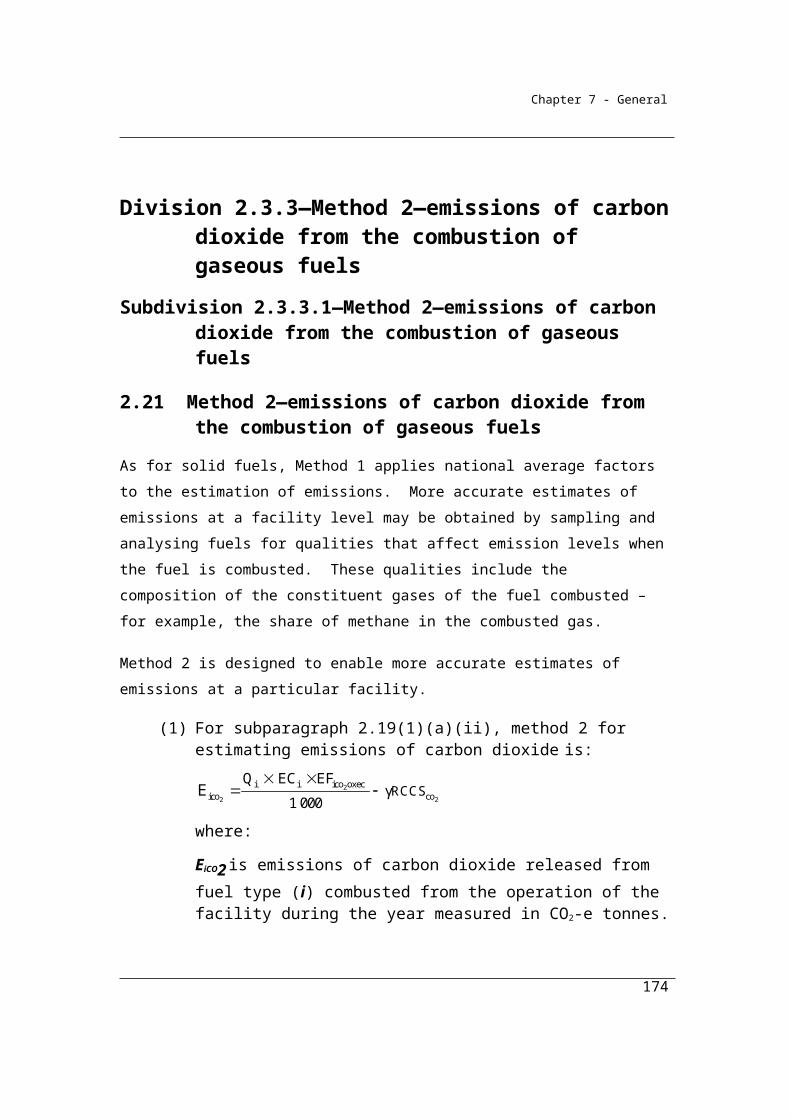
Chapter 7 - General
(2) The measurement must be carried out:(a) at the point of combustion at ambient temperatures and converted to
standard temperatures, using measuring equipment calibrated to a measurement requirement; or
(b) at ambient temperatures and converted to standard temperatures, at the point of sale of the liquid fuel, using measuring equipment calibrated to a measurement requirement.
(3) Paragraph (2)(b) only applies if:(a) the change in the stockpile of fuel for the facility for the year is less
than 1% of total combustion on average for the facility during the year; and
(b) the stockpile of the fuel for the facility at the beginning of the year is less than 5% of total combustion from the operation of the facility for the year.
2.53 Simplified consumption measurements—criterion BBB
For paragraph 2.50(4)(b), criterion BBB is the estimation of the combustion of a liquid fuel for the year using accepted industry measuring devices or, in the absence of such measuring devices, in accordance with industry practice if the equipment used to measure consumption of the fuel is not calibrated to a measurement requirement.
174
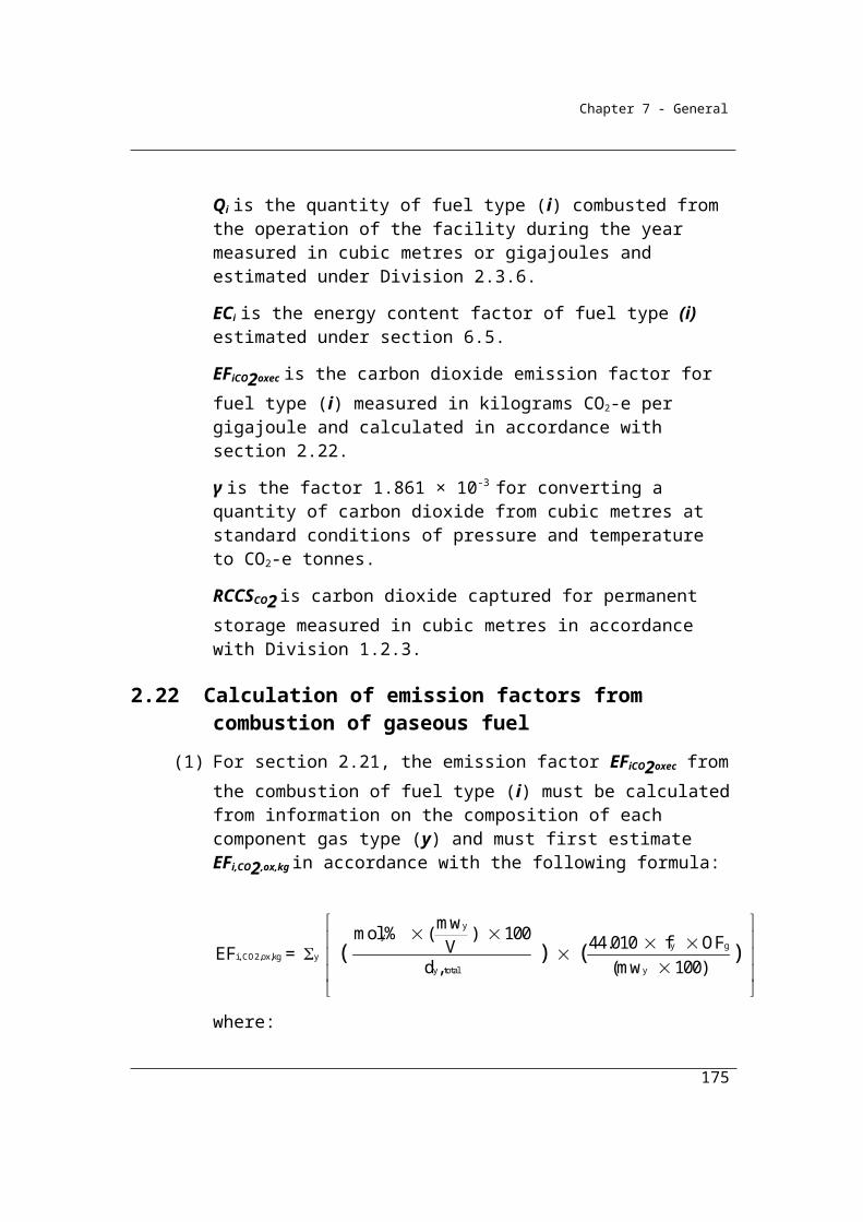
Chapter 7 - General
Part 2.5—Emissions released from fuel use by certain industries
2.54 Application
This Part applies to emissions from petroleum refining, solid fuel transformation (coke ovens) and petrochemical production.
Division 2.5.1—Energy—petroleum refining
2.55 Application
This Division applies to petroleum refining.
2.56 Methods
(1) If:(a) the operation of a facility is constituted by petroleum refining; and(b) the refinery combusts fuels for energy;
then the methods for estimating emissions during a year from that combustion are as provided in Parts 2.2, 2.3 and 2.4.
(2) The method for estimating emissions from the production of hydrogen by the petroleum refinery must be in accordance with the method set out in section 5 of the API Compendium.
(3) Fugitive emissions released from the petroleum refinery must be estimated using methods provided for in Chapter 3.
Division 2.5.2—Energy—manufacture of solid fuels
2.57 Application
This Division applies to solid fuel transformation through the pyrolysis of coal or the coal briquette process.
2.58 Methods
(1) One or more of the following methods must be used for estimating emissions during the year from combustion of fuels for energy in the manufacture of solid fuels:
175
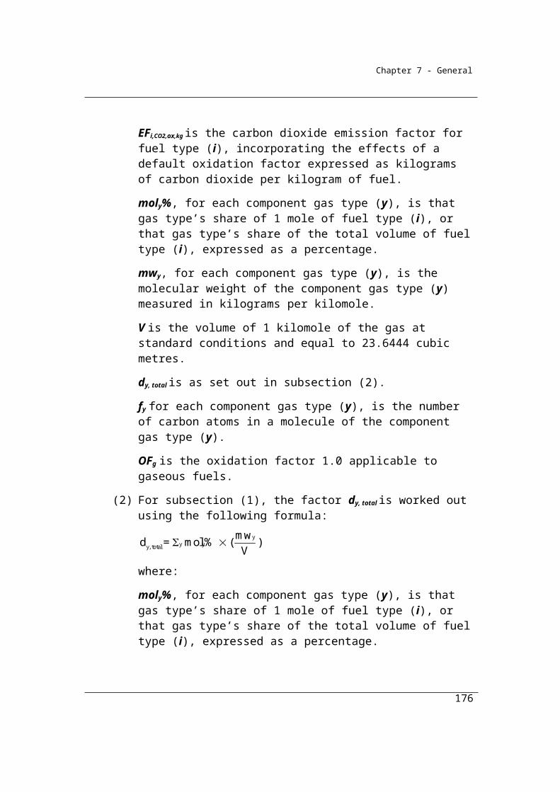
Chapter 7 - General
(a) if a facility is constituted by the manufacture of solid fuel using coke ovens as part of an integrated metalworks—the methods provided in Part 4.4 must be used; and
(b) in any other case—one of the following methods must be used:(i) method 1 under subsection (3);
(ii) method 2 under subsections (4) to (7);(iii) method 3 under subsections (8) to (10);(iv) method 4 under Part 1.3.
(2) These emissions are taken to be emissions from fuel combustion.
Method 1
(3) Method 1, based on a carbon mass balance approach, is:
Step 1 Work out the carbon content in fuel types (i) or carbonaceous input material delivered for the activity during the year, measured in tonnes of carbon, as follows:
i i i CCF Q where:
i means the sum of the carbon content values obtained for all fuel types (i) or carbonaceous input material.
CCFi is the carbon content factor mentioned in Schedule 3, measured in tonnes of carbon, for each appropriate unit of fuel type (i) or carbonaceous input material consumed during the year from the operation of the activity.
Qi is the quantity of fuel type (i) or carbonaceous input material delivered for the activity during the year, measured in an appropriate unit and estimated in accordance with criterion A in Divisions 2.2.5, 2.3.6 and 2.4.6.
176
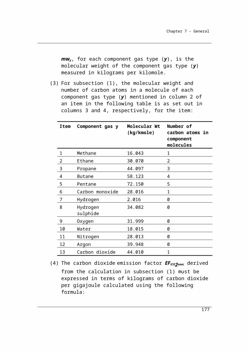
Chapter 7 - General
Step 2 Work out the carbon content in products (p) leaving the activity during the year, measured in tonnes of carbon, as follows:
p pp CCF A
where:
p means the sum of the carbon content values obtained for all product types (p).CCFp is the carbon content factor, measured in tonnes of carbon, for each tonne of product type (p) produced during the year.Ap is the quantity of product types (p) produced leaving the activity during the year, measured in tonnes.
Step 3 Work out the carbon content in waste by-product types (r) leaving the activity, other than as an emission of greenhouse gas, during the year, measured in tonnes of carbon, as follows:
r rr CCF Y
where:
r means the sum of the carbon content values obtained for all waste by-product types (r).CCFr is the carbon content factor, measured in tonnes of carbon, for each tonne of waste by-product types (r).Yr is the quantity of waste by-product types (r) leaving the activity during the year, measured in tonnes.
Step 4 Work out the carbon content in the amount of the change in stocks of inputs, products and waste by-products held within the boundary of the activity during the year, measured in tonnes of carbon, as follows:
p p ap r r yri i qi CCF S + CCF S + CCF S
where:
i has the same meaning as in step 1.CCFi has the same meaning as in step 1.ΔSqi is the change in stocks of fuel type (i) for the activity and held within the boundary of the activity during the year, measured in tonnes.
177
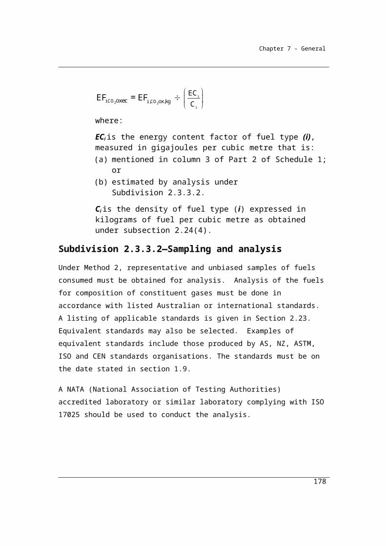
Chapter 7 - General
p has the same meaning as in step 2.CCFp has the same meaning as in step 2.
ΔSap is the change in stocks of product types (p) produced by the activity and held within the boundary of the activity during the year, measured in tonnes.
r has the same meaning as in step 3.CCFr has the same meaning as in step 3.ΔSyr is the change in stocks of waste by-product types (r) produced from the operation of the activity and held within the boundary of the activity during the year, measured in tonnes.
Step 5 Work out the emissions of carbon dioxide released from the operation of the activity during the year, measured in CO2-e tonnes, as follows:
(a) add the amounts worked out under steps 2, 3 and 4 to work out a new amount (amount A);
(b) subtract amount A from the amount worked out under step 1 to work out a new amount (amount B);
(c) multiply amount B by 3.664 to work out the amount of emissions released from the operation of the activity during the year.
Method 2
(4) Subject to subsections (5) to (7), method 2 is the same as method 1 under subsection (3).
(5) In applying method 1 as method 2, step 4 in subsection (3) is to be omitted and the following step 4 substituted.
178
13.664
Chapter 7 - General
Step 4 Work out the carbon content in the amount of the change in stocks of inputs, products and waste by-products held within the boundary of the activity during the year, measured in tonnes of carbon, as follows:
2p p ap r r yr coi i qi CCF S CCF S CCF S RCCS+ + + γ
where:
i has the same meaning as in step 1.CCFi has the same meaning as in step 1.ΔSqi is the change in stocks of fuel type (i) for the activity and held within the boundary of the activity during the year, measured in tonnes.
p has the same meaning as in step 2.CCFp has the same meaning as in step 2.ΔSap is the change in stocks of product types (p) produced by the activity and held within the boundary of the activity during the year, measured in tonnes.r has the same meaning as in step 3.
CCFr has the same meaning as in step 3.
ΔSyr is the change in stocks of waste by-product types (r) produced from the operation of the activity and held within the boundary of the activity during the year, measured in tonnes.α is the factor for converting the mass of carbon dioxide to a mass of carbon.
γ is the factor 1.861 × 10⁻³ for converting a quantity of carbon dioxide from cubic metres at standard conditions of pressure and temperature to CO2-e tonnes.RCCSCO2 is carbon dioxide captured for permanent storage, measured in cubic metres in accordance with Division 1.2.3.
(6) If a fuel type (i) or carbonaceous input material delivered for the activity during the year accounts for more than 5% of total carbon input for the activity, based on a calculation using the factors specified in Schedule 3, sampling and analysis of fuel type (i) or carbonaceous input material must be carried out to determine its carbon content.
179
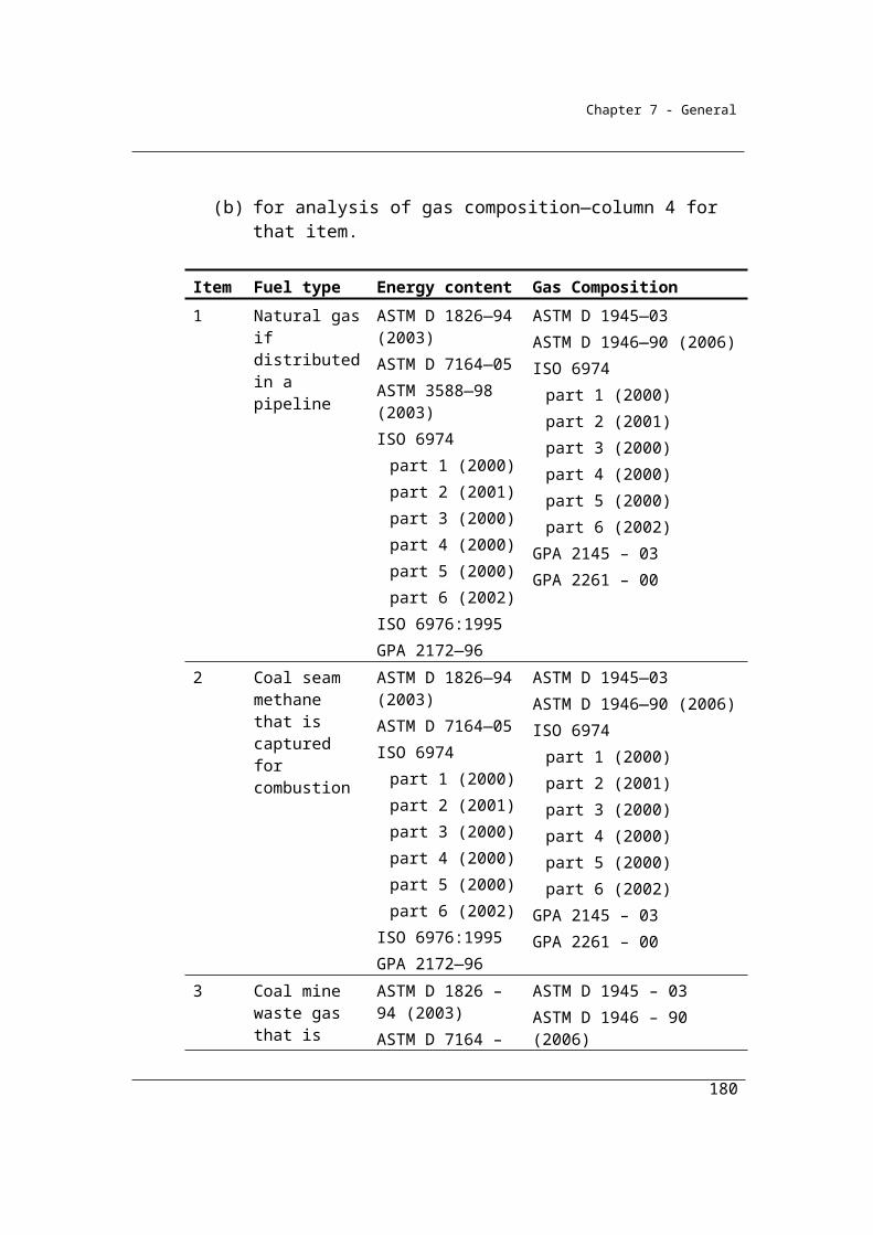
Chapter 7 - General
(7) The sampling and analysis is to be carried out using the sampling and analysis provided for in Divisions 2.2.3, 2.3.3 and 2.4.3 that apply to the combustion of solid, gaseous and liquid fuels.
Method 3
(8) Subject to subsections (9) and (10), method 3 is the same as method 2 under subsections (4) to (7).
(9) If a fuel type (i) or carbonaceous input material delivered for the activity during the year accounts for more than 5% of total carbon input for the activity, based on a calculation using the factors specified in Schedule 3, sampling and analysis of fuel type (i) or carbonaceous input material must be carried out to determine its carbon content.
(10) The sampling and analysis is to be carried out using the methods set out in Divisions 2.2.4, 2.3.4 and 2.4.4 that apply to the combustion of solid, gaseous and liquid fuels.
Estimating emissions from standalone coke production using method 1
An example for estimating emissions from a standalone coke production facility using
the method 1 carbon mass balance approach is provided below. The example uses
coking coal and fuel oil to produce coke. The facility also produces coal tar and waste
in the form of un-oxidised carbon, in addition to experiencing stock changes during
the year. The relevant data for the coke production facility is outlines in the table
below:
180
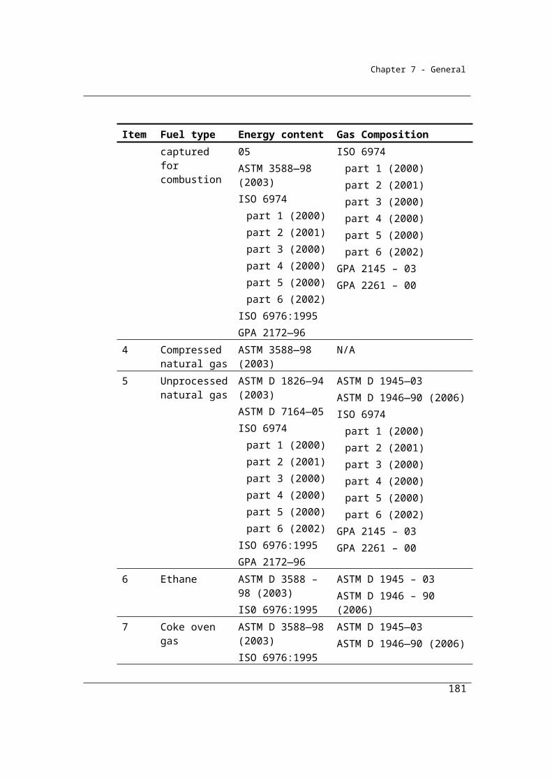
Chapter 7 - General
Fuel or product type
Fuels delivered during the year
Products produced and
leaving the activity during
the year
Change (increase) in
stocks during the year
Carboncontentfactor
(CCF)
Coke oven coke
9,000 tonnes -300 tonnes 0.789
Coking coal 14,500 tonnes 500 tonnes 0.752
Fuel oil 100 kilolitres 0.797
Step 1 Calculate the carbon content in fuel types (i) or carbonaceous input material
delivered for the activity during the year measured in tonnes of carbon as follows:
Where:
CCFi is the carbon content factor mentioned in Appendix A measured in tonnes of
carbon for each appropriate unit of fuel type (i) or carbonaceous input material
consumed during the year from the operation of the activity.
The Method 1 default carbon content factors can be found in Schedule 3 of the NGER
(Measurement) Determination and are shown in the table above.
Qi is the quantity of fuel type (i) or carbonaceous input material delivered for the
activity during the year measured in an appropriate unit and estimated in accordance
with criterion A in Division 2.2.5, 2.3.6 and 2.4.6. In this case the quantities of input
materials are shown in the table above:
To calculate the carbon content for the input materials:
181
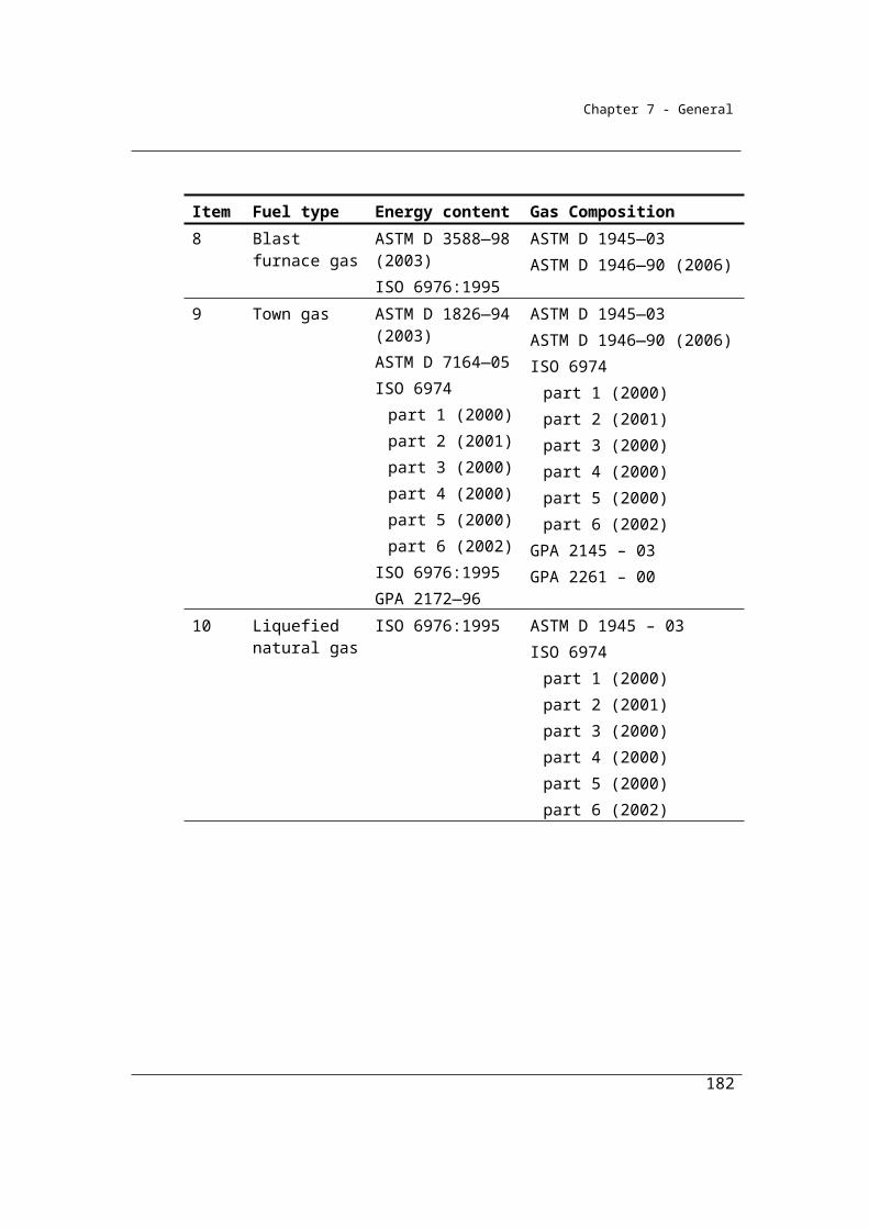
Chapter 7 - General
Carbon content of coking coal = (14,500 x 0.752) = 10,904 tonnes of carbon
Carbon content of fuel oil = (100 x 0.797) = 79.7 tonnes of carbon
Therefore, total carbon = (10,904 + 79.7) = 10,983.7 tonnes
Step 2 Calculate the carbon content in products (p) leaving the activity during the
year measured in tonnes of carbon as follows:
Where:
CCFp is the carbon content factor measured in tonnes of carbon for each tonne of
product type (p) produced during the year. In this case the carbon content factor of
each product type is shown in the table above:
Ap is the quantity of product types (p) produced leaving the activity during the year
measured in tonnes. In this case the quantity of products are shown in the table above:
To calculate the carbon content for the products leaving the activity
during the year:
Carbon content of coke oven coke = (9,000 x 0.789) = 7,101 tonnes of carbon
Carbon content of coal tar = (400 x 0.837) = 334.8 tonnes of carbon
Therefore, total carbon = (7,101 + 334.8) = 7435.8 tonnes
182
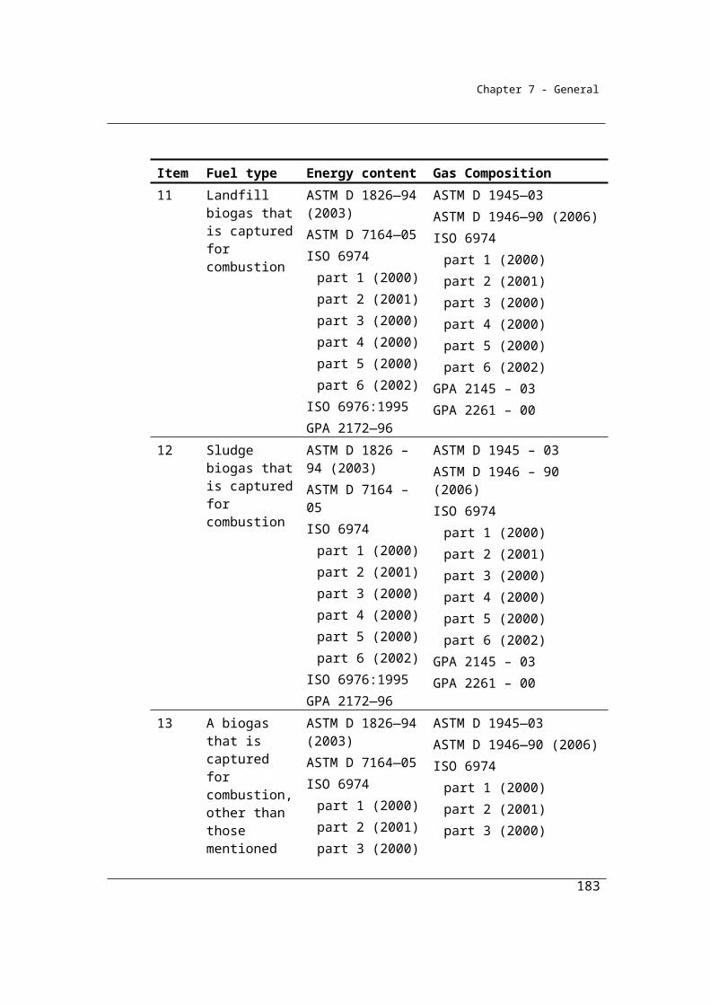
Chapter 7 - General
Step 3 Calculate the carbon content in waste by product types (r) leaving the activity,
other than as an emission of greenhouse gas, during the year, measured in tonnes of
carbon, as follows:
Where:
CCFr is the carbon content factor measured in tonnes of carbon for each tonne of
waste by product types (r).
Yr is the quantity of waste by product types (r) leaving the activity during the year
measured in tonnes. In this case the quantities of waste by-products are non-oxidised
carbon, estimated in accordance with the NGER (Measurement) Determination as
being 100 tonnes.
To calculate the carbon content for the waste products leaving the activity
during the year:
Carbon content of non-oxidised carbon = 100 tonnes of carbon
Therefore, total carbon = 100 tonnes
Step 4 Calculate the carbon content in the amount of the increase in stocks of inputs,
products and waste by products held within the boundary of the activity during the
year in tonnes of carbon as follows:
Where:
183

Chapter 7 - General
CCFi has the same meaning as in step 1.
ΔSqi is the increase in stocks of fuel type (i) for the activity and held within the
boundary of the activity during the year measured in tonnes. In this case the quantities
of increases in stocks are shown in the table above:
To calculate the carbon content for increase of fuel types
Carbon content of coking coal = (500 x 0.752) = 376 tonnes of carbon
Therefore, total carbon = 376 tonnes
CCFp has the same meaning as in step 2.
ΔSap is the increase in stocks of product types (p) produced by the activity and held
within the boundary of the activity during the year measured in tonnes. In this case the
quantities of product types shown in the table above:
To calculate the carbon content for increase in stock of product type:
Carbon content of coal tar = (20 x 0.837) = 16.74 tonnes of carbon
Carbon content of coke oven coke = (-300 x 0.789) = -236.7 tonnes of carbon
Therefore, total carbon = (16.74 + -236.7) = -219.96 tonnes
CCFr has the same meaning as in step 3.
ΔSyr is the increase in stocks of waste by product types (r) produced from the
operation of the activity and held within the boundary of the activity during the year
measured in tonnes.
184
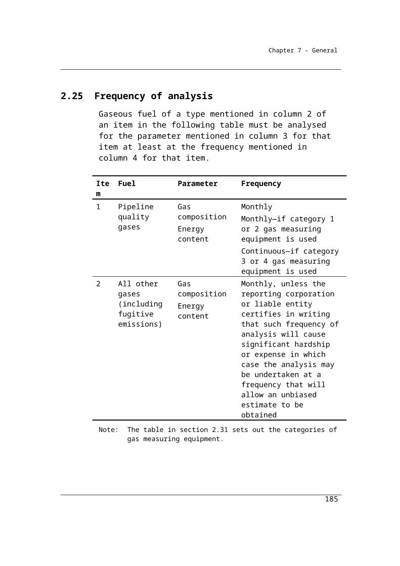
Chapter 7 - General
There was no change in waste product stock produced and held during the year.
To calculate the total carbon contained in the change of stock:
Carbon content of increase in fuel types = 376 tonnes
Carbon content of increase in product types = -219.96 tonnes
Carbon content of increase in waste by-products = 0 tonnes
Therefore, total carbon = (376 + -219.6 + 0) = 156.04 tonnes
Step 5 Calculate the emissions of carbon dioxide released from the operation of the
activity during the year measured in CO2 e tonnes as follows:
(a) add the amounts worked out under steps 2, 3 and 4 to work out a new
amount (amount A);
In this case A is:
= 7435.8 + 100 + 156.04
= 7,691.84 tonnes of carbon
(b) subtract amount A from the amount worked out under step 1 to work
out a new amount (amount B);
In this case:
= 10,983.7 7,691.84
= 3,291.86 tonnes of carbon
185

Chapter 7 - General
(c) multiply amount B by 3.664 to work out the amount of emissions
released from the operation of the activity during a year.
= 3,291.86 x 3.664
= 12,061.37504 tonnes CO2-e
Therefore, total carbon balance CO2 emissions from the source = 12,061 tonnes
186
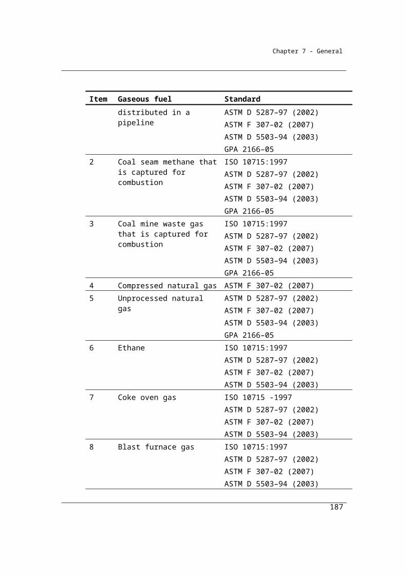
Chapter 7 - General
Division 2.5.3—Energy—petrochemical production
2.59 Application
This Division applies to petrochemical production (where fuel is consumed as a feedstock).
2.60 Available methods
(1) Subject to section 1.18 one of the following methods must be used for estimating emissions released during a year from the operation of a facility that is constituted by an activity that is petrochemical production:
(a) method 1 under section 2.61;(b) method 2 under section 2.62;(c) method 3 under section 2.63;(d) method 4 under Part 1.3.
(2) However, for incidental emissions another method may be used that is consistent with the principles in section 1.13.
2.61 Method 1—petrochemical production
Method 1, based on a carbon mass balance approach, is:
Step 1 Calculate the carbon content in all fuel types (i) delivered for the activity during the year as follows:
i i i CCF Q
where:i means sum the carbon content values obtained for all fuel types (i).CCFi is the carbon content factor measured in tonnes of carbon for each tonne of fuel type (i) as mentioned in Schedule 3 consumed in the operation of the activity.Qi is the quantity of fuel type (i) delivered for the activity during the year measured in tonnes and estimated in accordance with criterion A in Divisions 2.2.5, 2.3.6 and 2.4.6.
187
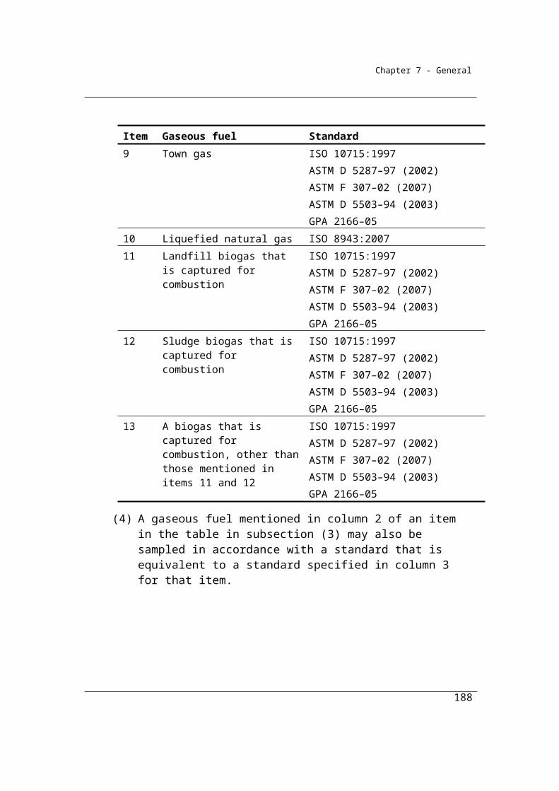
Chapter 7 - General
Step 2 Calculate the carbon content in products (p) leaving the activity during the year as follows:
p p p CCF A
where:p means sum the carbon content values obtained for all product types (p).
CCFp is the carbon content factor measured in tonnes of carbon for each tonne of product (p).
Ap is the quantity of products produced (p) leaving the activity during the year measured in tonnes.
Step3 Calculate the carbon content in waste by-products (r) leaving the activity, other than as an emission of greenhouse gas, during the year as follows:
r r r CCF Y
where:r means sum the carbon content values obtained for all waste by-product types (r).CCFr is the carbon content factor measured in tonnes of carbon for each tonne of waste by-product (r).Yr is the quantity of waste by-product (r) leaving the activity during the year measured in tonnes.
188
Chapter 7 - General
Step 4 Calculate the carbon content in the amount of the increase in stocks of inputs, products and waste by-products held within the boundary of the activity during the year as follows:
i i qi p p ap r r yr CCF S + CCF S + CCF S
where:
i has the same meaning as in step 1.CCFi has the same meaning as in step 1.ΔSqi is the increase in stocks of fuel type (i) for the activity and held within the boundary of the activity during the year measured in tonnes.p has the same meaning as in step 2.CCFp has the same meaning as in step 2.ΔSap is the increase in stocks of products produced (p) by the activity and held within the boundary of the activity during the year measured in tonnes.
r has the same meaning as in step 3.CCFr has the same meaning as in step 3.ΔSyr is the increase in stocks of waste by-products (r) produced by the activity and held within the boundary of the activity during the year measured in tonnes.
Step 5 Calculate the emissions of carbon dioxide released from the activity during the year measured in CO2-e tonnes as follows:
(a) add the amounts worked out under steps 2, 3 and 4 to work out a new amount (amount A)
(b) subtract amount A from the amount worked out under step 1 to work out a new amount (amount B);
(c) multiply amount B by 3.664 to work out the amount of emissions released from the activity during a year.
2.62 Method 2—petrochemical production
(1) Subject to subsections (2) and (3), method 2 is the same as method 1 under section 2.61 but sampling and analysis of fuel types (i) is used to determine carbon content of the fuel.
(2) The sampling and analysis is to be carried out using the methods set out in Divisions 2.2.3, 2.3.3 and 2.4.3 that apply to the combustion of solid, liquid or gaseous fuels.
189
13.664
Chapter 7 - General
(3) In applying method 1 as method 2, step 4 in section 2.61 is to be omitted and the following step 4 substituted:
Step 4 Calculate the carbon content in the amount of the increase in stocks of inputs, products and waste by-products held within the boundary of the activity during the year as follows:
2i i qi p p ap r r yr co CCF S + CCF S + CCF S + α γRCCS
where:
i has the same meaning as in step 1.CCFi has the same meaning as in step 1.
ΔSqi is the increase in stocks of fuel type (i) for the activity and held within the boundary of the activity during the year measured in tonnes.
p has the same meaning as in step 2.
CCFp has the same meaning as in step 2.
ΔSap is the increase in stocks of products produced (p) by the activity and held within the boundary of the activity during the year measured in tonnes.
r has the same meaning as in step 3.CCFr has the same meaning as in step 3.ΔSyr is the increase in stocks of waste by-products (r) produced by the activity and held within the boundary of the activity during the year measured in tonnes.α is the factor for converting the mass of carbon dioxide to a mass of carbon.
γ is the factor 1.861 x 10⁻³ for converting a quantity of carbon dioxide from cubic metres at standard conditions of pressure and temperature to CO2-e tonnes.RCCSCO2 is carbon dioxide captured for permanent storage measured in cubic metres in accordance with Division 1.2.3.
190
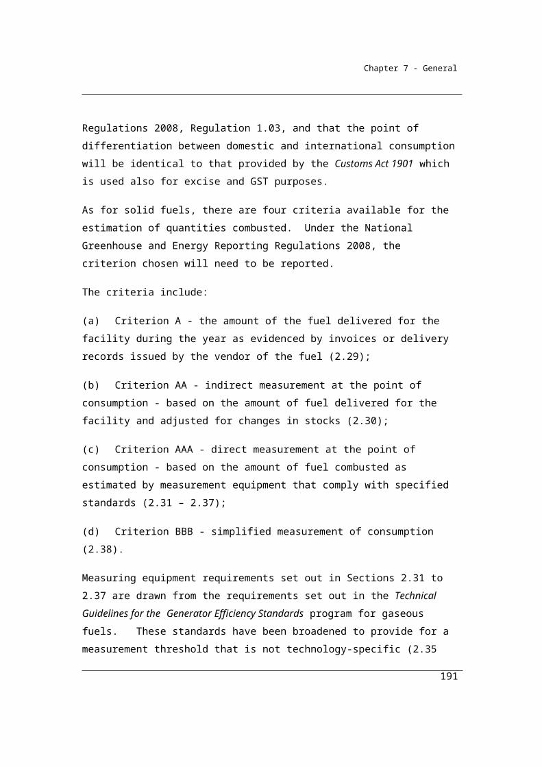
13.664
Chapter 7 - General
2.63 Method 3—petrochemical production
(1) Subject to subsections (2) and (3), method 3 is the same as method 1 in section 2.61 but the sampling and analysis of fuel types (i) is used to determine carbon content of the fuel.
(2) The sampling and analysis is to be carried out using the methods set out in Divisions 2.2.4, 2.3.4 and 2.4.4 that apply to the combustion of solid, liquid or gaseous fuels.
(3) In applying method 1 as method 3, step 4 in section 2.61 is to be omitted and the following step 4 substituted.
Step 4 Calculate the carbon content in the amount of the increase in stocks of inputs, products and waste by-products held within the boundary of the activity during the year as follows:
2i i qi p p ap r r yr co CCF S + CCF S + CCF S + αγRCCS
where:
i has the same meaning as in step 1.CCFi has the same meaning as in step 1.ΔSqi is the increase in stocks of fuel type (i) for the activity and held within the boundary of the activity during the year measured in tonnes.p has the same meaning as in step 2.CCFp has the same meaning as in step 2.ΔSap is the increase in stocks of products produced (p) by the activity and held within the boundary of the activity during the year measured in tonnes.
r has the same meaning as in step 3.CCFr has the same meaning as in step 3.ΔSyr is the increase in stocks of waste by-products (r) produced by the activity and held within the boundary of the activity during the year measured in tonnes.α is the factor for converting the mass of carbon dioxide to a mass of carbon.
191
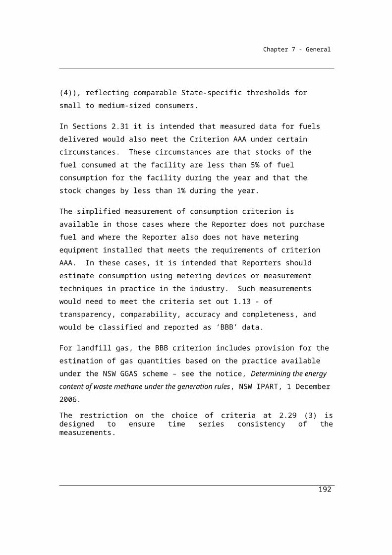
Chapter 7 - General
γ is the factor 1.861 x 10⁻³ for converting a quantity of carbon dioxide from cubic metres at standard conditions of pressure and temperature to CO2-e tonnes.RCCSCO2 is carbon dioxide captured for permanent storage measured in cubic metres in accordance with Division 1.2.3.
192
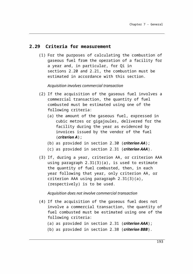
Chapter 7 - General
Part 2.6—Blended fuels
2.64 Purpose
This Part sets out how to determine the amounts of each kind of fuel that is in a blended fuel.
2.65 Application
This Part sets out how to determine the amount of each fuel type (i) that is in a blended fuel if that blended fuel is a solid fuel or a liquid fuel.
2.66 Blended solid fuels
(1) In determining the amounts of each kind of fuel that is in a blended solid fuel, a person may adopt the outcome of the sampling and analysis done by the manufacturer of the fuel if:
(a) the sampling has been done in accordance with subsections 2.12(3) and (4); and
(b) the analysis has been done in accordance with one of the following standards or a standard that is equivalent to one of those standards:(i) CEN/TS15440:2006;
(ii) ASTM D6866—10.
(2) The person may use his or her own sampling and analysis of the fuel if the sampling and analysis complies with the requirements of paragraphs (1)(a) and (b).
2.67 Blended liquid fuels
The person may adopt the manufacturer’s determination of each kind of fuel that is in a blended liquid fuel or adopt the analysis arrived at after doing both of the following:
(a) sampling the fuel in accordance with a standard mentioned in subsections 2.47(3) and (4);
(b) analysing the fuel in accordance with ASTM: D6866—10 or a standard that is equivalent to that standard.
These standards include the following approaches to quantification:
193

Chapter 7 - General
Manual sorting (CEN/TS 15440:2006)
The manual sorting technique involves a sample of the solid blended fuel being sorted by hand into sub-fractions of biomass and non-biomass matter.
This procedure however is limited to fuels with a minimum particle size greater than 1 cm and only applies to blends of solid fuels.
Selective dissolution (CEN/TS 15440:2006)
The selective dissolution method for the determination of the biomass content involves the treatment of a sample of blended solid fuel with concentrated sulphuric acid topped with hydrogen peroxide. The biomass in the solid recovered fuel will selectively dissolve and the non-biomass will remain in the residue.
This technique is not applicable to the following blended fuels:
charcoal, peat and solid fossil fuels like hard coal, coke, brown coal and lignite and to mixtures of these and solid recovered fuels;
solid recovered fuels that contain more than 10 % of natural and/or synthetic rubber residues;
solid recovered fuels that contain a combination of more than 5 % by weight of:
o nylon, polyurethane or other polymers containing molecular amino groups;
o biodegradable plastics of fossil origin;
solid recovered fuels that contain a combination of more than 5 % by weight of:
o wool or viscose;
o non-biodegradable plastics of biogenic origin;
o oil or fat present as a constituent of biomass.
Radiocarbon Analysis
The ASTM D 6866-08 standard also provides for a radiocarbon analysis method. The standard describes techniques for determining the biogenic content of solid, liquid and gaseous samples using radiocarbon analysis. The basic premise is that Carbon-14 (14C), a radioactive isotope of carbon, has a half life of 5,730 years once it is no
194
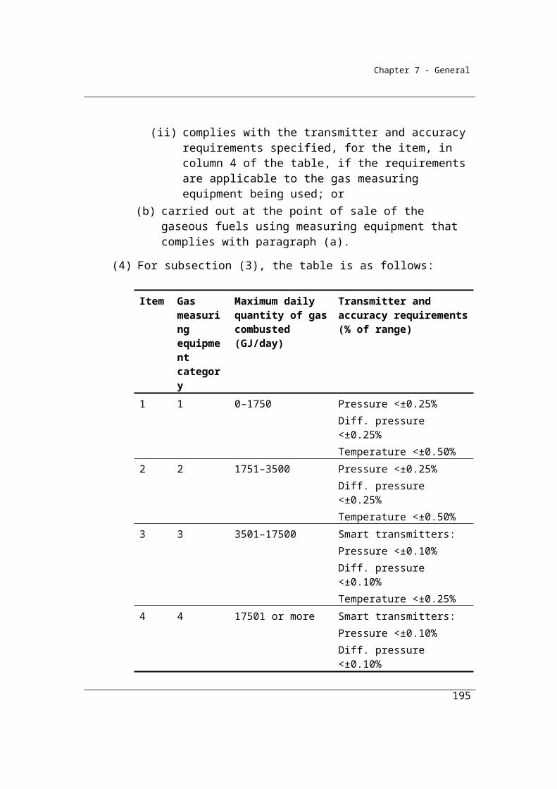
Chapter 7 - General
longer part of a living organism. This means that no 14C will remain in fossil fuels because it has completely decayed, whereas in recent biomass, such as wood, a portion of 14C still remains.
In effect, it is argued that biogenic matter contains a well characterized amount of carbon-14 that is easily distinguished from other materials such as fossil fuels that do not contain any carbon-14. Since the amount of carbon-14 in biomass is well known, a percentage of biogenic carbon can be calculated easily from the overall carbon atoms in the sample.
This technique may be applied to any type of blended fuel including gaseous, liquid and solid fuels. The technique may be used to analyse the fuels directly or can be used to analyse the combustion gases once the fuel has being burned. The latter technique may be useful where direct emissions monitoring systems are already in place to measure CO2 emissions and where sampling fuels can be difficult.
195
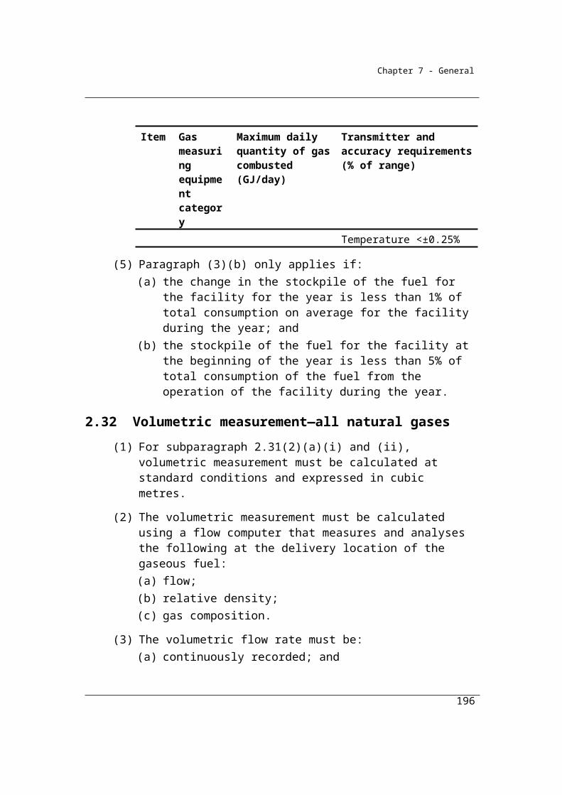
Chapter 7 - General
Part 2.7—Estimation of energy for certain purposes
2.68 Amount of energy consumed without combustion
For paragraph 4.22(1)(b) of the Regulations:(a) the energy is to be measured:
(i) for solid fuel—in tonnes estimated under Division 2.2.5; or(ii) for gaseous fuel—in cubic metres estimated under
Division 2.3.6; or(iii) for liquid fuel—in kilolitres estimated under Division 2.4.6; and(iv) for electricity—in kilowatt hours:
(A) worked out using the evidence mentioned in paragraph 6.5(2)(a); or
(B) if the evidence mentioned in paragraph 6.5(2)(a) is unavailable—estimated in accordance with paragraph 6.5(2)(b).
(b) the reporting threshold is:(i) for solid fuel—20 tonnes; or
(ii) for gaseous fuel—13 000 cubic metres; or(iii) for liquid fuel—15 kilolitres; or(iv) for electricity consumed from a generating unit with a
maximum capacity to produce less than 0.5 megawatts of electricity—100 000 kilowatt hours; or
(v) for all other electricity consumption—20 000 kilowatt hours.Example: A fuel is consumed without combustion when it is used as a solvent or a
flocculent, or as an ingredient in the manufacture of products such as paints, solvents or explosives.
Examples of non-combustive use of fuels
When used directly in a non-fuel manner – for example, fuels used directly as a solvent or a flocculent;
When used as an ingredient in the manufacture of short-life products such as paints, cleaning agents and explosives manufactured for sale;
When packaged for non-internal combustion engine use (restricted to containers less than 20 litres and kerosene, mineral turpentine, white spirit, liquid aromatic
196
Chapter 7 - General
hydrocarbons and other petroleum products as defined in 10.28 of the schedule to the Excise Tariff Act);
When blended with other products and then packaged for non-internal combustion engine use;
When unprocessed natural gas is consumed to create natural gas distributed in a pipeline.
Some uses of petroleum based oils and greases. Division 2.4.5A provides more guidance on the reporting of petroleum based oils and greases.
Note the reporting thresholds in 2.68 apply to each fuel type individually. For example, where a facility consumes 10 kL of diesel and 10 kL of solvents for non-combustion purposes this facility is not required to report under this provision.
2.69 Apportionment of fuel consumed as carbon reductant or feedstock and energy
(1) This section applies, other than for Division 2.5.3, if:(a) a fuel type as provided for in a method is consumed from the
operation of a facility as either a reductant or a feedstock; and(b) the fuel is combusted for energy; and(c) the equipment used to measure the amount of the fuel for the
relevant purpose was not calibrated to a measurement requirement.Note: Division 2.5.3 deals with petrochemicals. For petrochemicals, all fuels,
whether used as a feedstock, a reductant or combusted as energy are reported as energy.
(2) The amount of the fuel type consumed as a reductant or a feedstock may be estimated:
(a) in accordance with industry measuring devices or industry practice; or
(b) if it is not practicable to estimate as provided for in paragraph (a)—to be the whole of the amount of the consumption of that fuel type from the operation of the facility.
(3) The amount of the fuel type combusted for energy may be estimated as the difference between the total amount of the fuel type consumed from the operation of the facility and the estimated amount worked out under subsection (2).
197
Chapter 7 - General
2.70 Amount of energy consumed in a cogeneration process
Cogeneration processes are situations where two products – electricity and another product – are produced from the consumption of a single quantity of fuel.
This section specifies that for the purpose of complying with the National Greenhouse and Energy Reporting Regulations 2008, subregulation 4.23 (3), the quantity of fuel consumed and allocated to the production of electricity should be estimated using the efficiency method as described in the Allocation of Emissions from a Combined Heat and Power (CHP) Plant Guide to calculation worksheets (September 2006) v1.0 (the cogeneration guide) issued by World Resource Institute and World Business Council for Sustainable Development unless the heat is to be used for producing mechanical work when the work potential method described in the cogeneration guide may be used.
The efficiency method is the preferred method of the World Resource Institute and World Business Council for Sustainable Development. Limiting the approaches that can be used provides for more consistent interpretation of reported data and establishes well-understood boundaries for all data reported.
(1) For subregulation 4.23(3) of the Regulations and subject to subsection (3), the method is the efficiency method.
(2) The efficiency method is as described in the publication entitled Allocation of Emissions from a Combined Heat and Power (CHP) Plant Guide to calculation worksheets (September 2006) v1.0 issued by the World Resource Institute and World Business Council for Sustainable Development.
(3) Where heat is to be used mainly for producing mechanical work, the work potential method may be used.
(4) The work potential method is as described in the publication entitled Allocation of Emissions from a Combined Heat and Power (CHP) Plant Guide to calculation worksheets (September 2006) v1.0 issued by the World Resource Institute and World Business Council for Sustainable Development.
198
Chapter 7 - General
2.71 Apportionment of energy consumed for electricity, transport and for stationary energy
Apportionment of fuels consumed between various purposes is considered to be less critical than the overall estimate of fuel consumed for a facility. Consequently, allocations of fuels consumed between purposes may be determined by facility records based on facility measurement techniques.
For the purpose of determining fuels consumed in transport, road transport means fuel consumed by a vehicle registered for road use.
Subject to section 2.70, the amount of fuel type (i) consumed by a reporting corporation or liable entity that is apportioned between electricity generation, transport (excluding international bunker fuels) and other stationary energy purposes may be determined using the records of the corporation or liable entity if the records are based on the measurement equipment used by the corporation or the liable entity to measure consumption of the fuel types.
199

Chapter 7 - General
Appendix 2A Notes on Energy and Emission Factors
The following notes apply to energy content and emission factors in the following tables:
Table 2.2.2
Table 2.3.2
Table 2.4.2A
Table 2.4.2B
Table 2.4.5A
Table 2.4.5B
1. Energy value: Source – DCCEE analysis of NGER reporting data for reporting years 2008-09
to 2010-11 and industry advice. CO2 emission factor: Source - National Inventory Report 2006,
Department of Climate Change. Non-CO2 factors: Source: AGEIS database, Department of Climate
Change and Energy Efficiency and Energy Efficiency.
1A. Energy value: Source – DCCEE analysis of NGER reporting data for reporting years 2008-09
to 2010-11 and industry advice. CO2 emission factor: Source - National Inventory Report 2006,
Department of Climate Change. Non-CO2 factors: Source: AGEIS database, Department of Climate
Change and Energy Efficiency and Energy Efficiency.
1B. Energy value: Source – DCCEE analysis of NGER reporting data for reporting years 2008-09
to 2010-11 and industry advice. CO2 emission factor: Source - National Inventory Report 2006,
Department of Climate Change. Non-CO2 factors: Source: AGEIS database, Department of Climate
Change and Energy Efficiency and Energy Efficiency.
2. Energy value: Source – AGEIS database, Department of Climate Change and Energy
Efficiency (based on facility reports). CO2 emission factor: Source - AGEIS database, Department of
Climate Change and Energy Efficiency (based on facility reports). Non-CO2 factors: Source: AGEIS
database, Department of Climate Change and Energy Efficiency.
200

Chapter 7 - General
3. Energy value: Source – ABARE1 (washed coking). CO2 emission factor: Source - National
Inventory Report 2006, Department of Climate Change. Non-CO2 factors: Source: AGEIS database,
Department of Climate Change and Energy Efficiency.
4. Energy value: Source – ABARE1. CO2 emission factor: Source - AGEIS database,
Department of Climate Change and Energy Efficiency (based on facility reports). Non-CO2 factors:
Source: AGEIS database, Department of Climate Change and Energy Efficiency.
5. Energy value: Source – ABARE1. CO2 emission factor: Source – National Inventory Report
2006, Department of Climate Change. Non-CO2 factors: Source: AGEIS database, Department of
Climate Change and Energy Efficiency.
6. Energy value: Source – ABARE1. CO2 emission factor: Source – National Inventory Report
2006, Department of Climate Change (coal tar). Non-CO2 factors: Source: AGEIS database,
Department of Climate Change and Energy Efficiency.
7. See (4)
8. Energy value: Source – GHD Review of Sectoral Models, Internal report to the AGO, 2006.
CO2 emission factor: Source – National Inventory Report 2006, Department of Climate Change. Non-
CO2 factors: Source: AGEIS database, Department of Climate Change and Energy Efficiency.
9. Energy value: Source – IPCC 2006. Derived from NCV using factor of 5% of gross calorific
value. CO2 emission factor: Source: IPCC 2006. Derived using conversion factor of 0.95. Non-CO2
factors: Source: IPCC 2006. Derived using conversion factor of 0.95.
10. Energy value: Source: ABARE1 (dry wood). Non-CO2 factors: Source: AGEIS database,
Department of Climate Change and Energy Efficiency.
11. Energy value: Source: ABARE1 (green wood). Non-CO2 factors: Source: AGEIS database,
Department of Climate Change and Energy Efficiency.
12. Energy value: Source – IPCC 2006. Derived from NCV using factor of 5% of gross calorific
value. Non-CO2 factors: Source: IPCC 2006. Derived using conversion factor of 0.95.
201
Chapter 7 - General
13. Energy value: Source: ABARE1. Non-CO2 factors: Source: AGEIS database, Department of
Climate Change and Energy Efficiency.
14. Energy value: Source – IPCC 2006. Derived from NCV using factor of 5% of gross calorific
value. Non-CO2 factors: Source: IPCC 2006. Derived using conversion factor of 0.95.
15. Energy value: Source – IPCC 2006. Derived from NCV using factor of 5% of gross calorific
value. Non-CO2 factors: Source: IPCC 2006. Derived using conversion factor of 0.95.
16. See (14)
17. Energy value: Source: ABARE1 (weighted average). CO2 emission factor: Source - AGEIS
database, Department of Climate Change and Energy Efficiency. Non-CO2 factors: Source: AGEIS
database, Department of Climate Change and Energy Efficiency.
18. Energy value: Source: ABARE1 (coal seam methane). CO2 emission factor: Source - AGEIS
database, Department of Climate Change and Energy Efficiency. Non-CO2 factors: Source: AGEIS
database, Department of Climate Change and Energy Efficiency.
19. Energy value: Source: ABARE1 (coal seam methane). CO2 emission factor: Source - AGEIS
database, Department of Climate Change and Energy Efficiency. Non-CO2 factors: Source: AGEIS
database, Department of Climate Change and Energy Efficiency.
20. See (17)
21. See (17)
22. Energy value: Source: ABARE1 (weighted average). CO2 emission factor: Source – National
Inventory Report 2006, Department of Climate Change. Non-CO2 factors: Source: AGEIS database,
Department of Climate Change and Energy Efficiency.
202

Chapter 7 - General
23. Energy value: Source: ABARE1. CO2 emission factor: Source – National Inventory Report
2006, Department of Climate Change. Non-CO2 factors: Source: AGEIS database, Department of
Climate Change and Energy Efficiency.
24. Energy value: Source – ABARE1. CO2 emission factor: Source: IPCC 2006. Derived using
conversion factor of 0.90. Non-CO2 factors: Source: IPCC 2006. Derived using conversion factor of
0.90.
25. Energy value: Source – ABARE2 (synthetic natural gas). CO2 emission factor: Source:
National Inventory Report 2006, Department of Climate Change. Non-CO2 factors: Source: AGEIS
database.
26. Energy value: Source – ABARE1. CO2 emission factor: Source - AGEIS database,
Department of Climate Change and Energy Efficiency. Non-CO2 factors: Source: AGEIS database,
Department of Climate Change and Energy Efficiency.
27. See (17)
28. Energy value: Source – ABARE1. Non-CO2 factors: Source: AGEIS database, Department of
Climate Change and Energy Efficiency.
29. Energy value: Source – ABARE1. Non-CO2 factors: Source: AGEIS database, Department of
Climate Change and Energy Efficiency.
30. See (28)
31. Energy value: Source – ABARE2 (lubricants and greases). CO2 emission factor:
Source: National Inventory Report 2006, Department of Climate Change (lubricants and greases). Oxidation factor 0.2. Non-CO2 factors: nil
32. Energy value: Source – ABARE2 (lubricants and greases). CO2 emission factor:
Source: National Inventory Report 2006, Department of Climate Change (lubricants and greases). Oxidation factor 0. Non-CO2 factors: nil.
203
Chapter 7 - General
33. Energy value: Source – ABARE2 (weighted average). CO2 emission factor: Source: IPCC
2006. Derived using conversion factor of 0.95. Non-CO2 factors: IPCC 2006 (Energy Industries).
Derived using conversion factor of 0.95.
34. Energy value: Source – IPCC 2006. Derived from NCV using factor of 5% of gross calorific
value. CO2 emission factor: Source: IPCC 2006. Derived using conversion factor of 0.95. Non-CO2
factors: IPCC 2006 (Energy Industries). Derived using conversion factor of 0.95.
35. Energy value: Source – ABARE2. CO2 emission factor: Source: National Inventory Report
2006, Department of Climate Change. Non-CO2 factors: AGEIS database, Department of Climate
Change and Energy Efficiency.
36. Energy value: Source – ABARE2. CO2 emission factor: Source: National Inventory Report
2006, Department of Climate Change. Non-CO2 factors: AGEIS database, Department of Climate
Change and Energy Efficiency.
37. Energy value: Source – ABARE2 (power kerosene). CO2 emission factor: Source:
National Inventory Report 2006, Department of Climate Change. Non-CO2 factors: AGEIS database,
Department of Climate Change and Energy Efficiency.
38. Energy value: Source – ABARE2. CO2 emission factor: Source: National Inventory Report
2006, Department of Climate Change. Non-CO2 factors: AGEIS database, Department of Climate
Change and Energy Efficiency.
39. Energy value: Source – ABARE2. CO2 emission factor: Source: National Inventory Report
2006, Department of Climate Change. Non-CO2 factors: AGEIS database, Department of Climate
Change and Energy Efficiency.
40. Energy value: Source – ABARE2. CO2 emission factor: Source National Inventory Report
2006, Department of Climate Change. Non-CO2 factors: AGEIS database, Department of Climate
Change and Energy Efficiency.
204

Chapter 7 - General
41. Energy value: Source – ABARE2 (low sulphur). CO2 emission factor: Source: National
Inventory Report 2006, Department of Climate Change. Derived using conversion factor of 0.95. Non-
CO2 factors: AGEIS database, Department of Climate Change and Energy Efficiency.
42. Energy value: Source – ABARE2. Given same energy content as solvents. CO2 emission
factor: Source: National Inventory Report 2006, Department of Climate Change (assumed same as
solvents). Non-CO2 factors: AGEIS database, Department of Climate Change and Energy Efficiency.
43. Energy value: Source – ABARE2. CO2 emission factor: National Inventory Report 2006,
Department of Climate Change. Derived using conversion factor of 0.95. Non-CO2 factors: AGEIS
database, Department of Climate Change and Energy Efficiency.
44. Energy value: Source – ABARE2. CO2 emission factor: Source: National Inventory Report
2006, Department of Climate Change. Non-CO2 factors: AGEIS database, Department of Climate
Change and Energy Efficiency.
45. Energy value: Source – ABARE2. CO2 emission factor: Source: National Inventory Report
2006, Department of Climate Change. Non-CO2 factors: AGEIS database, Department of Climate
Change and Energy Efficiency.
46. Energy value: Source – IPCC 2006. CO2 emission factor: Source: IPCC 2006. Derived using
conversion factor of 0.95. Non-CO2 factors: IPCC 2006, Manufacturing category. Derived using
conversion factor 0.95.
47. Energy value: Source – ABARE1 (refinery fuel). CO2 emission factor: Source: IPCC 2006.
Derived using conversion factor of 0.95. Non-CO2 factors: IPCC 2006. Derived using conversion
factor 0.95.
48. See (46)
49. Energy value: Source – ABARE2. Based on IPCC 2006, given same energy content as
solvents. CO2 emission factor: Source National Inventory Report 2006, Department of Climate Change
(set same as solvents). Non-CO2 factors: AGEIS database, Department of Climate Change and Energy
Efficiency.
205
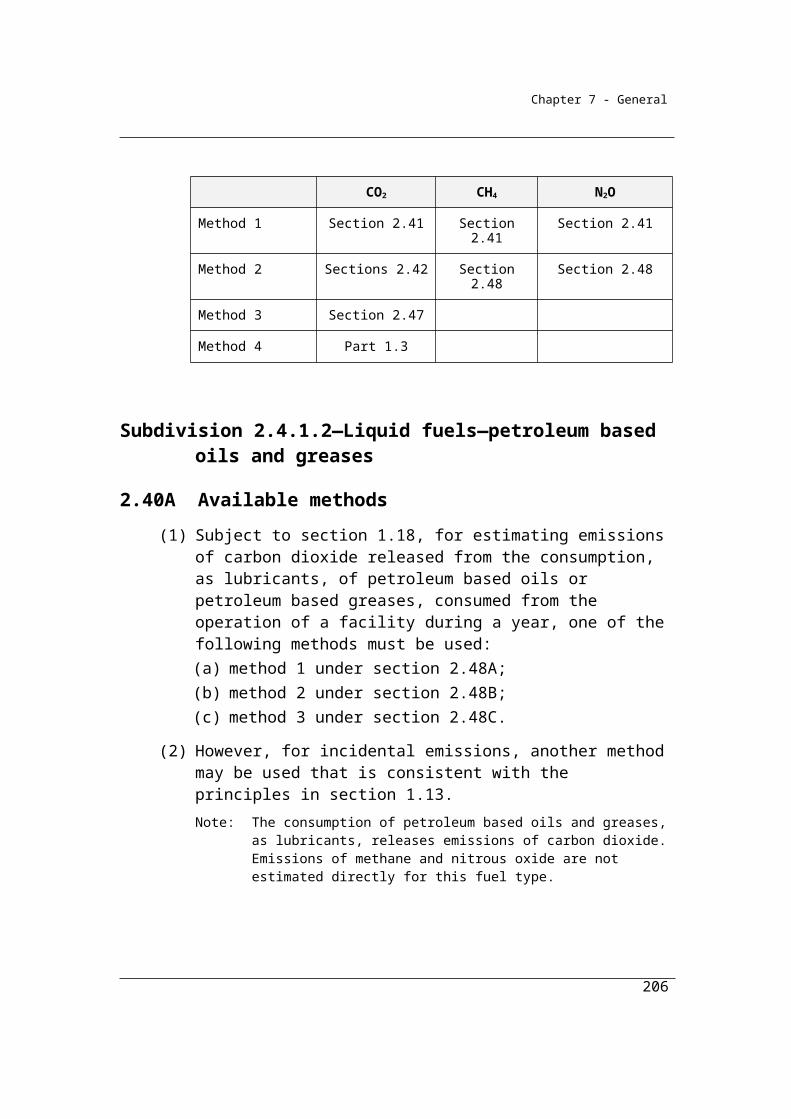
Chapter 7 - General
50. Energy value: Source – Derived from US Department of Energy. Non-CO2 factors: IPCC
2006. Derived using conversion factor 0.95.
51. Energy value: Source – ABARE2. Non-CO2 factors: IPCC 2006. Derived using conversion
factor 0.95.
52. See (51).
53. Energy value: Source – ABARE2. CO2 emission factor: Source: National Inventory Report
2006, Department of Climate Change. Non-CO2 factors: AGEIS database Department of Climate
Change and Energy Efficiency.
54. Energy value: Source – ABARE2. CO2 emission factor: Source: National Inventory Report
2006, Department of Climate Change. Non-CO2 factors: AGEIS database Department of Climate
Change and Energy Efficiency.
55. Energy value: Source – ABARE2. CO2 emission factor: Source: National Inventory Report
2006, Department of Climate Change. Non-CO2 factors: AGEIS database, Department of Climate
Change and Energy Efficiency.
56. Energy value: Source – ABARE2. CO2 emission factor: Source: National Inventory Report
2006, Department of Climate Change. Non-CO2 factors: AGEIS database Department of Climate
Change and Energy Efficiency.
57. Energy value: Source – ABARE2 (low sulphur). CO2 emission factor: Source: National
Inventory Report 2006, Department of Climate Change. Derived using conversion factor of 0.95. Non-
CO2 factors: AGEIS database Department of Climate Change and Energy Efficiency.
58. Energy value: Source – Derived from ABARE2. CO2 emission factor: Source: National
Inventory Report 2006, Department of Climate Change. Non-CO2 factors: AGEIS database
Department of Climate Change and Energy Efficiency.
206
Chapter 7 - General
59. Energy value: Source – Derived from US Department of Energy, 2006. Non-CO2 factors:
IPCC 2006. Derived using conversion factor 0.95.
60. Energy value: Source – ABARE2. Non-CO2 factors: IPCC 2006. Derived using conversion
factor 0.95.
61. See (60)
62. Energy value: Source: ABARE1 (weighted average). CO2 emission factor: Source - AGEIS
database, Department of Climate Change and Energy Efficiency. Non-CO2 factors: AGEIS database,
Department of Climate Change and Energy Efficiency.
63. Energy value: Source: ABARE1 (weighted average). CO2 emission factor: Source - AGEIS
database, Department of Climate Change and Energy Efficiency. Non-CO2 factors: AGEIS database,
Department of Climate Change and Energy Efficiency.
63A Energy value: Source – ABARE1. CO2 emission factor: Source - AGEIS database,
Department of Climate Change and Energy Efficiency. Non-CO2 factors: Source: AGEIS database,
Department of Climate Change and Energy Efficiency
64B Energy value: Source – ABARE1. CO2 emission factor: Source - AGEIS database,
Department of Climate Change and Energy Efficiency. Non-CO2 factors: Source: AGEIS database,
Department of Climate Change and Energy Efficiency
64. Energy value: Source – ABARE2. CO2 emission factor: Source: National Inventory Report
2006, Department of Climate Change. Non-CO2 factors: Derived from AGEIS database, Department
of Climate Change and Energy Efficiency.
65. Energy value: Source – ABARE2. CO2 emission factor: Source: National Inventory Report
2006, Department of Climate Change. Non-CO2 factors: Derived from AGEIS database, Department
of Climate Change and Energy Efficiency.
207

Chapter 7 - General
66. Energy value: Source – ABARE2. CO2 emission factor: Source: National Inventory Report
2006, Department of Climate Change. Non-CO2 factors: Derived from AGEIS database, Department
of Climate Change and Energy Efficiency.
67. Energy value: Source – ABARE2. Non-CO2 factors: Derived from AGEIS database,
Department of Climate Change and Energy Efficiency.
68. Energy value: Source – ABARE2. CO2 emission factor: Source: National Inventory Report
2006, Department of Climate Change. Non-CO2 factors: Derived from AGEIS database, Department
of Climate Change and Energy Efficiency.
69. Energy value: Source – ABARE2. CO2 emission factor: Source National Inventory Report
2006, Department of Climate Change. Non-CO2 factors: Derived from AGEIS database, Department
of Climate Change and Energy Efficiency.
70. Energy value: Source – ABARE2. CO2 emission factor: Source National Inventory Report
2006, Department of Climate Change. Non-CO2 factors: Derived from AGEIS database, Department
of Climate Change and Energy Efficiency.
208

Chapter 7 - General
Chapter 3—Fugitive emissions
Part 3.1—Preliminary
3.1 Outline of Chapter
This Chapter provides for fugitive emissions from the following:(a) coal mining (see Part 3.2);(b) oil and natural gas (see Part 3.3);(c) carbon capture and storage (see Part 3.4).
Part 3.2—Coal mining—fugitive emissions
Division 3.2.1—PreliminaryThe principal sources of fugitive greenhouse gases from coal mining include emissions from underground and open cut mining activities and emissions from decommissioned mines. A small amount of emissions are also associated with flaring coal mine waste gas and post-mining activities such as from the stockpiling of coal. This chapter describes the methods for estimating emissions from each of these sources.
Other sources of emissions arising from the coal production process, such as from the combustion of fuels for energy (e.g. electricity production), are not described in this chapter and must be estimated using the Methods described in other chapters.
3.2 Outline of Part
This Part provides for fugitive emissions from coal mining, as follows:(a) underground mining activities (see Division 3.2.2);(b) open cut mining activities (see Division 3.2.3);(c) decommissioned underground mines (see Division 3.2.4).
209

Chapter 7 - General
Division 3.2.2—Underground mines
Subdivision 3.2.2.1—Preliminary
Fugitive emissions from underground mines involve the release of methane and carbon dioxide during the mining process due to the fracturing of coal seams, overburden and underburden strata. Emissions also arise from post mining activities such as the stockpiling of coal from the release of residual gases within the coal not released during the mining process. Emissions also occur when coal mine waste gas is flared.
3.3 Application
This Division applies to fugitive emissions from underground mining activities (other than decommissioned underground mines).
3.4 Available methods
(1) Subject to section 1.18, for estimating emissions released during a year from the operation of a facility that is constituted by underground mining activities (other than decommissioned underground mines) the methods as set out in this section must be used.
Methane from extraction of coal
(2) Method 4 under section 3.6 must be used for estimating fugitive emissions of methane that result from the extraction of coal from the underground mine.Note: There is no method 1, 2 or 3 for subsection (2).
Carbon dioxide from extraction of coal
(3) Method 4 under section 3.6 must be used for estimating fugitive emissions of carbon dioxide that result from the extraction of coal from the underground mine. Note: There is no method 1, 2 or 3 for subsection (3).
Flaring
(4) For estimating emissions released from coal mine waste gas flared from the underground mine:
210
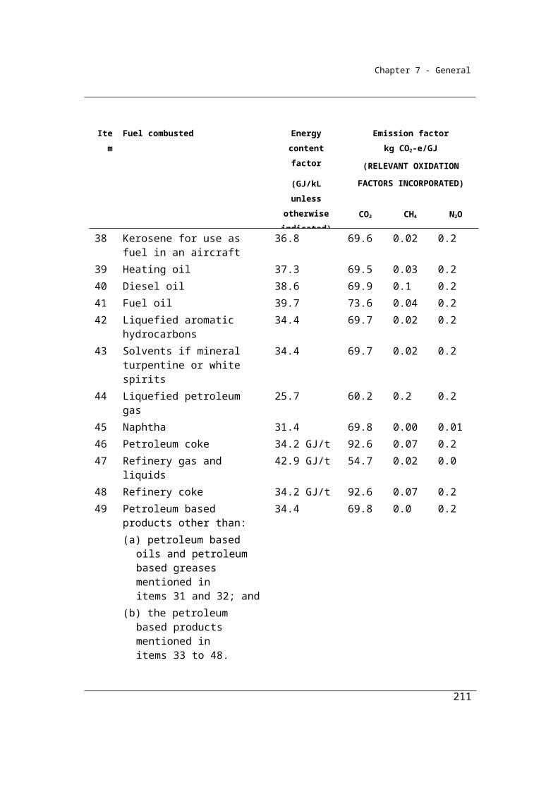
Chapter 7 - General
(a) one of the following methods must be used for estimating emissions of carbon dioxide released:(i) method 1 under section 3.14;
(ii) method 2 under section 3.15;(iii) method 3 under section 3.16; and
(b) one of the following methods must be used for estimating emissions of methane released:(i) method 1 under section 3.14;
(ii) method 2 under section 3.15A; and(c) one of the following methods must be used for estimating emissions
of nitrous oxide released:(i) method 1 under section 3.14;
(ii) method 2 under section 3.15A.Note: The flaring of coal mine waste gas releases emissions of carbon dioxide,
methane and nitrous oxide. The reference to gas type (j) in method 1 under section 3.14 or method 2 under section 3.15A is a reference to these gases. The same formula in Method 1 is used to estimate emissions of each of these gases. There is no method 4 for emissions of carbon dioxide and no method 3 or 4 for emissions of methane or nitrous oxide.
Venting or other fugitive release before extraction of coal
(5) Method 4 under Part 1.3 must be used for estimating fugitive emissions of each gas type, being carbon dioxide and methane, that result from venting or other fugitive release of gas from the underground mine before coal is extracted from the mine.Note: There is no method 1, 2 or 3 for subsection (5).
Post-mining activities
(6) Method 1 under section 3.17 must be used for estimating fugitive emissions of methane that result from post-mining activities related to a gassy mine.Note: There is no method 2, 3 or 4 for subsection (6).
(7) However, for incidental emissions, another method may be used that is consistent with the principles in section 1.13.
211
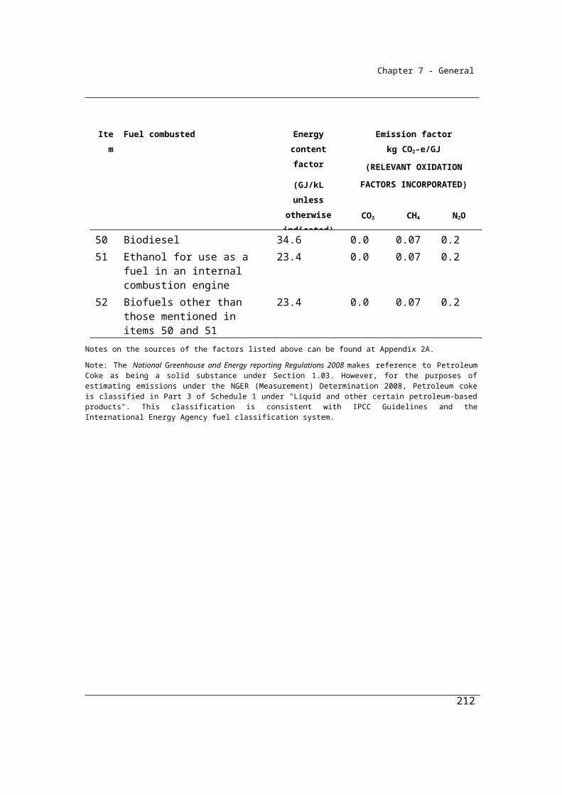
Chapter 7 - General
Summary of available methods, for estimating emissions from underground mines, by emissions of gas type (j)
CO2 CH4 N2O
Underground mining activities
Method 1 NA NA NO
Method 2, 3 NA NA NO
Method 4 Section 3.6 Section 3.6 NO
Post-mining Activities
Method 1 NA Section 3.17 NO
Methods 2, 3 and 4 NA NA NO
Flaring
Method 1 Section 3.14 Section 3.14 Section 3.14
Method 2 Section 3.15 Section 3.15A Section 3.15A
Method 3 Section 3.16 NA NA
Method 4 NA NA NA
Venting
Methods 1, 2 and 3 NA NA NO
Method 4 Part 1.3 Part 1.3 NO
NA = Not available. NO = Not occurring
212

Chapter 7 - General
Subdivision 3.2.2.2—Fugitive emissions from extraction of coal
3.5 Method 1—extraction of coal
For subsection 3.32(1), method 1 is:
j jE = Q EF
where:
Ej is the fugitive emissions of methane (j) that result from the extraction of coal from the mine during the year measured in CO2-e tonnes.
Q is the quantity of run-of-mine coal extracted from the mine during the year measured in tonnes.
EFj is the emission factor for methane (j), measured in CO2-e tonnes per tonne of run-of-mine coal extracted from the mine, as follows:
(a) for a gassy mine—0.363;(b) for a non-gassy mine—0.010.
3.6 Method 4—extraction of coal
Method 4 for estimating emissions associated with underground mining operations involves directly measuring emissions within ventilation shafts and degasification systems. This Method is dealt with in detail in Part 1.3 of Chapter 1.
Estimation methods under current applicable state or territory legislation
In addition to the methods outlined in Part 1.3, Reporters may also directly measure emissions using periodic emissions measurement (PEM) in accordance with elements of relevant State Government legislation. This legislation includes the following:
Coal Mine Health and Safety Act 2002 (NSW) and the Coal Mine Health and Safety Regulation 2006 (NSW)
Coal Mining Safety and Health Act 1999 (Qld) and the Coal Mining Safety and Health Regulation 2001 (Qld).
213

Chapter 7 - General
It is intended that, as a minimum, existing practices for the monitoring of gases at underground mines may be maintained as input into the emissions estimation process under Method 4.
(1) For subsections 3.4(2) and (3), method 4 is:
j gen, totalj 2-e j ij,cap ij,flared ijtrE = CO Q + Q + Q
where:
Ej is the fugitive emissions of gas type (j) that result from the extraction of coal from the mine during the year, measured in CO2-e tonnes.
CO2-e j gen, total is the total mass of gas type (j) generated from the mine during the year before capture and flaring is undertaken at the mine, measured in CO2-e tonnes and estimated using the direct measurement of emissions in accordance with subsection (2).
γj is the factor for converting a quantity of gas type (j) from cubic metres at standard conditions of pressure and temperature to CO2-e tonnes, being:
(a) for methane—6.784 × 10-4 × 25; and(b) for carbon dioxide—1.861 × 10⁻³.
Qij,cap is the quantity of gas type (j) in coal mine waste gas type (i) captured for combustion from the mine and used during the year, measured in cubic metres and estimated in accordance with Division 2.3.6.
Qij,flared is the quantity of gas type (j) in coal mine waste gas type (i) flared from the mine during the year, measured in cubic metres and estimated in accordance with Division 2.3.6.
Qijtr is the quantity of gas type (j) in coal mine waste gas type (i) transferred out of the mining activities during the year measured in cubic metres.
(2) The direct measurement of emissions released from the extraction of coal from an underground mine during a year by monitoring the gas stream at the underground mine may be undertaken by one of the following:
(a) continuous emissions monitoring (CEM) in accordance with Part 1.3;
(b) periodic emissions monitoring (PEM) in accordance with sections 3.7 to 3.13.
Note: Any estimates of emissions must be consistent with the principles in section 1.13.
214

Chapter 7 - General
(3) For Qijtr in subsection (1), the quantity of gas type (j) must be estimated in accordance with Division 2.3.6 as if a reference in that Division to quantities of gaseous fuels combusted from the operation of a facility was a reference to quantities of gaseous fuels transferred out of the operation of a facility.
Emissions from diesel combustion emissions and the ambient CO2 in airWhen estimating fugitive emissions from underground mine, it is important be mindful that Ej in paragraph (1) above represents the fugitive emissions that result from the extraction of coal from the mine. Volumetric flow within underground coal mine ventilation systems may also include gases that arise from sources other than fugitive emissions such as;
fuel combustion diesel emissions arising from the use of machinery, while the machinery is in the underground mine, and
ambient carbon dioxide present in the air that was drawn into the mine ventilation intake.
To ensure accurate emission estimation it may be necessary to make a deduction of these non-fugitive source gasses from the gas volumes measured in mine ventilation systems.
The Determination provides methods for estimating fuel combustion emissions from diesel under Part 2.4, however no specific guidance is given on avoiding any double counting of those emissions entrained in mine ventilation measurements. To ensure accuracy, fuel combustion emissions arising from the use of machinery in the underground mine should be deducted from mine ventilation volumes.
Any deductions of fuel combustion emissions arising from the use of machinery in the underground mine must be done in accordance with the general principles in 1.13 of the Determination.
The Determination also provides no specific guidance on the deduction of ambient carbon dioxide from mine ventilation air. However, as in the case above for diesel combustion emissions, the estimation must be done in accordance with the general principles in 1.13 of the Determination.
215
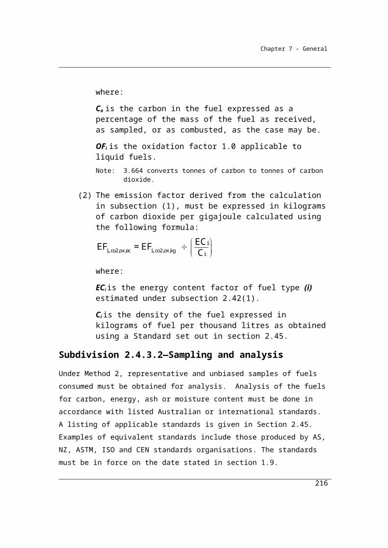
Chapter 7 - General
3.7 Estimation of emissions
This section describes how measurements of gas flow rates and concentrations are converted from volumetric flow rates to mass emission estimates.
(1) To obtain an estimate of the mass emissions rate of gas (j), being methane and carbon dioxide, at the time of measurement at the underground mine, the formula in subsection 1.21(1) must be applied.
(2) The mass of emissions estimated under the formula must be converted into CO2-e tonnes.
(3) The average mass emission rate for gas type (j) measured in CO2–e tonnes per hour for a year must be calculated from the estimates obtained under subsections (1) and (2).
(4) The total mass of emissions of gas type (j) from the underground mine for the year is calculated by multiplying the average emissions rate obtained under subsection (3) by the number of hours during the year.
3.8 Overview—use of equipment
The following requirements apply to the use of PEM equipment:(a) the requirements in section 3.9 about location of the sampling
positions for the PEM equipment; (b) the requirements in section 3.10 about measurement of volumetric
flow rates in a gas stream; (c) the requirements in section 3.11 about measurement of the
concentrations of gas type (j) in the gas stream; (d) the requirements in section 3.12 about representative data.(e) the requirements in section 3.13 about performance characteristics of
equipment.
3.9 Selection of sampling positions for PEM
For paragraph 3.8(a), an appropriate standard or applicable State or Territory legislation must be complied with for the location of sampling positions for PEM equipment.Note: Appropriate standards include:
AS 4323.1—1995/Amdt 1-1995, Stationary source emissions—Selection of sampling positions
216
Chapter 7 - General
USEPA Method 1—Sample and velocity traverses for stationary sources (2000)
3.10 Measurement of volumetric flow rates by PEM
For paragraph 3.8(b), the measurement of the volumetric flow rates by PEM of the gas stream must be undertaken in accordance with an appropriate standard or applicable State or Territory legislation. Note: Appropriate standards include:
ISO 14164:1999 Stationary source emissions. Determination of the volume flowrate of gas streams in ducts – automated method
ISO 10780:1994 Stationary source emissions. Measurement of velocity and volume flowrate of gas streams in ducts
USEPA Method 2—Determination of stack gas velocity and volumetric flow rate (Type S Pitot tube) (2000)
USEPA Method 2A—Direct measurement of gas volume through pipes and small ducts (2000).
3.11 Measurement of concentrations by PEM
For paragraph 3.8(c), the measurement of the concentrations of gas type (j) in the gas stream by PEM must be undertaken in accordance with an appropriate standard or applicable State or Territory legislation. Note: Appropriate standards include USEPA—Method 3C—Determination of
carbon dioxide, methane, nitrogen and oxygen from stationary sources (1996).
3.12 Representative data for PEM
(1) For paragraph 3.8(d), sampling by PEM must be undertaken during the year for a sufficient duration to produce representative data that may be reliably extrapolated to provide estimates of emissions across the full range of operating conditions for that year.
(2) Emission estimates of PEM equipment must also be consistent with the principles in section 1.13.
3.13 Performance characteristics of equipment
For paragraph 3.8(e), the performance characteristics of PEM equipment must be consistent with an appropriate standard or applicable State or Territory legislation.Note: The performance characteristics of PEM equipment includes calibration.
217
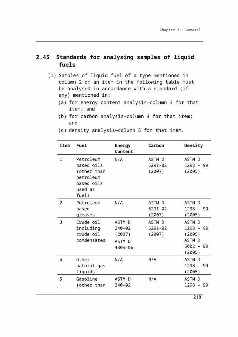
Chapter 7 - General
Subdivision 3.2.2.3—Emissions released from coal mine waste gas flared
3.14 Method 1—coal mine waste gas flared
Method 1 describes how to estimate greenhouse gas emissions from the flaring of coal mine waste gas - by multiplying the quantity of coal mine waste gas flared by the energy content and emission factor for each gas type. The quantity of coal mine waste gas flared is estimated in accordance with Division 2.3.6. The energy content and emission factors are obtained from Division 2.3.2 in Chapter 2.
For subparagraph 3.4(4)(a)(i) and paragraphs 3.4(4)(b) and (c), method 1 is:
i,flared i ij
iffl ij
Q EC EFE = OF
1000
where:
E(fl)ij is the emissions of gas type (j) released from coal mine waste gas (i) flared from the mine during the year, measured in CO2-e tonnes.
Qi,flared is the quantity of coal mine waste gas (i) flared from the mine during the year, measured in cubic metres and estimated under Division 2.3.6.
ECi is the energy content factor of coal mine waste gas (i) mentioned in item 19 of Schedule 1, measured in gigajoules per cubic metre.
EFij is the emission factor for gas type (j) and coal mine waste gas (i) mentioned in item 19 of Schedule 1, measured in CO2-e kilograms per gigajoule.
OFif is 0.98, which is the destruction efficiency of coal mine waste gas (i) flared.
218

Chapter 7 - General
3.15 Method 2—emissions of carbon dioxide from coal mine waste gas flared
Method 2 requires representative and unbiased samples of coal mine waste gas consumed and the analysis of the coal mine waste gas to determine gas composition. The methane and carbon dioxide content should be analysed and accounted for independently in accordance with Australian or equivalent international standards. The quantity of methane determined within the coal mine waste gas stream to be flared is applied to Section 3.15 to estimate carbon dioxide emissions and Section 3.15A to estimate methane and nitrous oxide emissions.
For subparagraph 3.4(4)(a)(ii), method 2 is:
where:
EiCO2 is the emissions of CO2 released from coal mine waste gas (i) flared from the mine during the year, measured in CO2-e tonnes.
ECi is the energy content factor of the methane (k) within coal mine waste gas (i) mentioned in item 19 of Schedule 1, measured in gigajoules per cubic metre.
EFk is the emission factor for the methane (k) within the fuel type from the mine during the year, measured in kilograms of CO2-e per gigajoule, estimated in accordance with Division 2.3.3.
OFi is 0.98, which is the destruction efficiency of coal mine waste gas (i) flared.
Qk is the quantity of methane (k) within the fuel type from the mine during the year, measured in cubic metres in accordance with Division 2.3.6.
QCO2 is the quantity of carbon dioxide within the coal mine waste gas emitted from the mine during the year, measured in CO2-e tonnes in accordance with Division 2.3.3.
219

Chapter 7 - General
3.15A Method 2—emissions of methane and nitrous oxide from coal mine waste gas flared
For subparagraphs 3.4(4)(b)(ii) and (c)(ii), method 2 is:
where:
Eij is the emissions of gas type (j), being methane or nitrous oxide, released from coal mine waste gas (i) flared from the mine during the year, measured in CO2-e tonnes.
ECi is the energy content factor of methane (k) within coal mine waste gas (i) mentioned in item 19 of Schedule 1, measured in gigajoules per cubic metre.
EFkj is the emission factor of gas type (j), being methane or nitrous oxide, for the quantity of methane (k) within coal mine waste gas (i) flared, mentioned in item 19 of Schedule 1 and measured in kilograms of CO2-e per gigajoule.
OFi is 0.98, which is the destruction efficiency of coal mine waste gas (i) flared.
Qk is the quantity of methane (k) within the coal mine waste gas (i) flared from the mine during the year, measured in cubic metres in accordance with Division 2.3.3.
3.16 Method 3—coal mine waste gas flared
Method 3 is the same as for Method 2 except that it requires samples to be obtained in accordance with Australian or equivalent international standards.
(1) For subparagraph 3.4(4)(a)(iii), method 3 is the same as method 2 under section 3.15.
(2) In applying method 2 under section 3.15, the facility specific emission
factor EFk must be determined in accordance with the procedure for
determining EFiCO2oxec in Division 2.3.4.
220
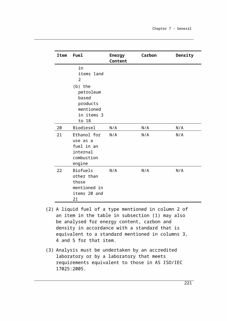
Chapter 7 - General
Estimating Carbon dioxide emissions from Coal mine waste gas flaring using
Method 2
Coal mining operations often involve the flaring of coal mine waste gas. In this example a
facility flares a coal mine waste gas stream from pre-drainage activities of 1,000,000
cubic meters (at standard pressure and temperature) during the year. The gas stream is
predominantly methane, but also contains some carbon dioxide and nitrogen. The
reporters have chosen to use method 2 to estimate emissions as this approach provides the
opportunity to develop a carbon dioxide emission factor that better reflects the methane
present in the gas stream, as well as account for the in-situ carbon dioxide quantity which
is emitted, but not combusted in the flare. The relevant data for the flaring of coal mine
waste gas are as follows in the table below:
Data inputs for carbon dioxide emissions from coal mine waste gas flaring example.
Quantity of coal mine waste gas flared (at
standard pressure and temperature)
(cubic metres)
Component gas type of coal mine
waste gas
gas type’s share of the total coal mine waste gas
volume
(%)
gas type’s volume
(cubic metres)
1,000,000
Methane 91 910,000
Carbon dioxide 7 70,000
Calculate the carbon dioxide emissions using Method 2 in section 3.15 of NGER
(Measurement) Determination
221
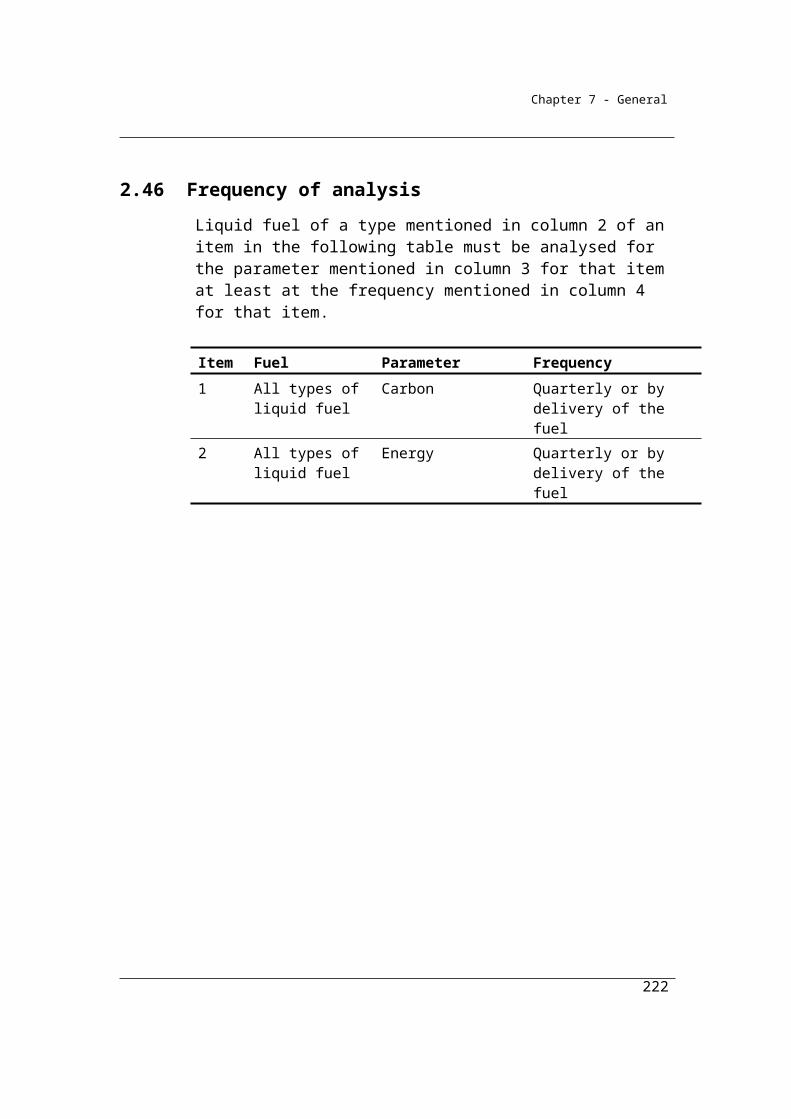
Chapter 7 - General
Where:
EiCO2 is the emissions of CO2 released from coal mine waste gas (i) flared from the mine
during the year, measured in CO2-e tonnes.
Qk is the quantity of methane (k) within the coal mine waste gas from the mine during the
year, measured in cubic metres in accordance with Division 2.3.3.
• This was determined by gas composition analysis of the coal mine waste gas (in
accordance with Division 2.3.3)
• The average methane composition of the coal mine waste gas being flared during
the year was estimated to be 91%.
• Therefore, to calculate the volume of methane within the coal mine waste gas:
Coal mine waste gas volume = 1,000,000
Methane composition = 91%
Total volume of methane (Qk) = 1,000,000 x 91/100 = 910,000 m3
QCO2 is the quantity of carbon dioxide within the coal mine waste gas emitted from the
mine during the year, measured in CO2-e tonnes in accordance with Division 2.3.3.
This was also determined by gas composition analysis of the coal mine waste gas(in
accordance with Division 2.3.3).
The average carbon dioxide composition of the coal mine waste gas being flared during
the year was 7%.
Therefore, to calculate the volume of carbon dioxide within the coal mine waste gas:
Coal mine waste gas volume = 1,000,000
222
Chapter 7 - General
Carbon dioxide composition = 7%
Total volume of carbon dioxide = 1,000,000 x 7/100 = 70,000 m3
Carbon dioxide m3 to tonnes conversion factor at standard pressure and temperature (see
Determination Section 3.21) = 1.861 x 10⁻³
Therefore:
QCO2 = 70,000 x 1.861 x 10-3
QCO2 = 130.27 tonnes of carbon dioxide
EFj is the emission factor for carbon dioxide resulting from the flaring of the methane
component (j) within the coal mine waste gas from the mine during the year, measured in
kilograms of CO2-e per gigajoule..
This is determined using Section 2.22, where in;
Section 2.22 (1) the mol% will be 100% methane as the EF is specifically for
methane only, and
o Section2.22 (4) the carbon dioxide emission factor for the flared methane has
been converted to kilograms of CO2-e per gigajoule, using:
The energy content of coal mine waste gas mentioned in item 19 of Schedule 1 of the
Determination.
The density of methane as calculated using its molecular weight in Section 2.22 (2)
• In this example it was estimated that the carbon dioxide emission factor for the
methane within the coal mine waste gas = 49.12525 kg CO2-e/GJ
223
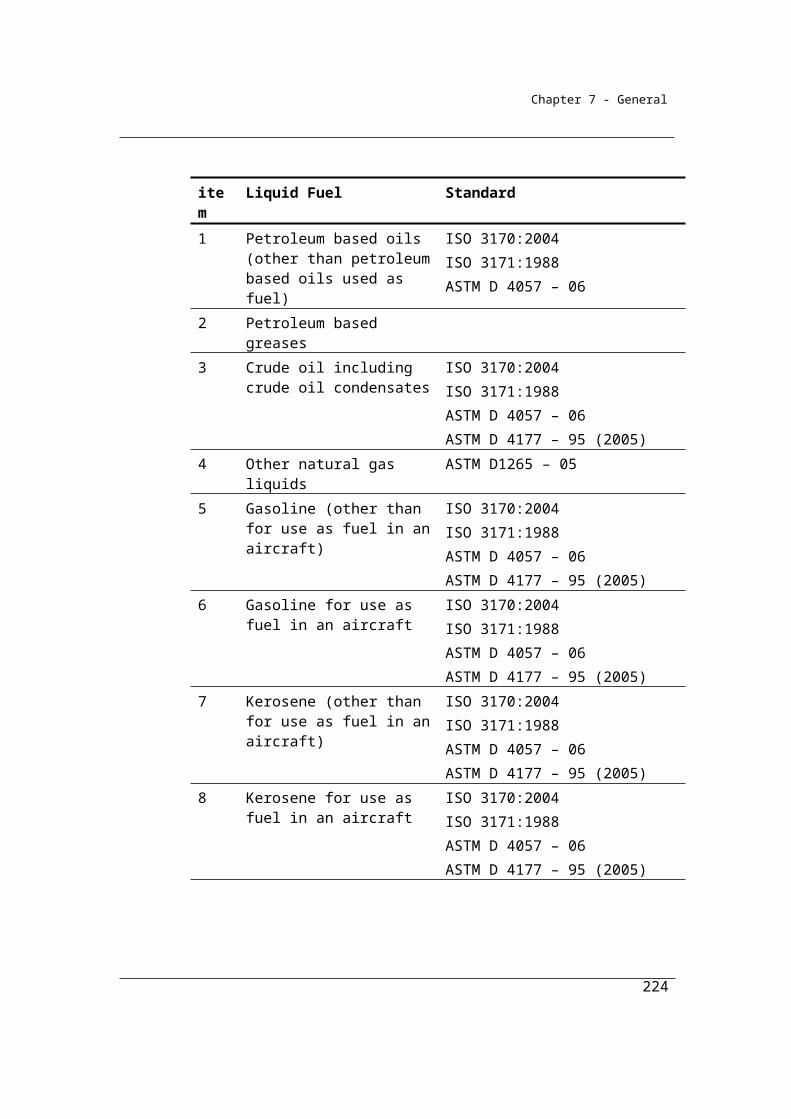
Chapter 7 - General
ECi is the energy content factor of methane within the coal mine waste gas (i), taken to be
equivalent to item 19 of Schedule 1 of the Determination, measured in gigajoules per
cubic metre.
• In this example the energy content for coal mine waste gas in Schedule 1 of the
NGER (Measurement) Determination = 37.7 x 10⁻³ GJ/m3
OFi = 0.98, which is the flaring efficiency factor of coal mine waste gas (i) flared.
Therefore, to calculate the CO2 emissions from coal mine waste gas flared:
Qj = 910,000 m3 of methane
ECi =37.7 x 10⁻³ GJ/m3
EFj = 49.12525 kg CO2-e/GJ
OFi = 0.98
QCO2 = 130.27 tonnes of carbon dioxide
= ((910,000 x 37.7 x 10-3 x 49.12525)/1000 x 0.98) + 130.27
= 1781.90325819221
Therefore, the total CO2 emissions from the flaring of coal seam waste gas = 1,781.90
tonnes.
Subdivision 3.2.2.4—Fugitive emissions from post-mining activities
Most fugitive greenhouse gas emissions are released from coal during the mining process. However some residual gas remains trapped within the coal after extraction, and is slowly released during, handling, transportation and stockpiling of the coal.
224
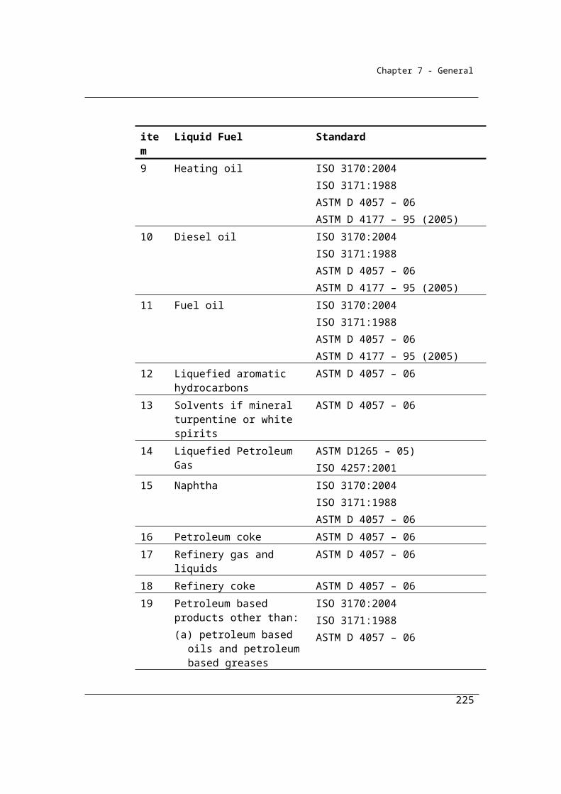
Chapter 7 - General
3.17 Method 1—post-mining activities related to gassy mines
Method 1 for estimating emissions from post-mining activities, with the source as described in IPCC 2006, is associated with gassy underground mines only.
The method is derived from the National Greenhouse Account national methodology as published in the National Inventory Report. Emissions are estimated by multiplying a (physical) quantity of run-of-mine coal extracted by an emission factor.
It is intended that consideration will be given to the development of additional higher order methods for this source in future.
(1) For subsection 3.4(6), method 1 is the same as method 1 under section 3.5.
(2) In applying method 1 under section 3.5, EFj is taken to be 0.017, which is the emission factor for methane (j), measured in CO2-e tonnes per tonne of run-of-mine coal extracted from the mine.
225
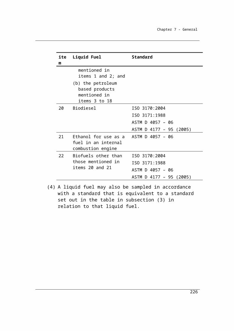
Chapter 7 - General
Division 3.2.3—Open cut minesFugitive emissions from open cut mines involve the release of methane and carbon dioxide during the mining process due to the fracturing of coal seams, overburden and underburden strata. Emissions also occur when coal mine waste gas is flared or is vented during degasification of the coal seams prior to the commencement of coal extraction.
Subdivision 3.2.3.1—Preliminary
3.18 Application
This Division applies to fugitive emissions from open cut mining activities.
3.19 Available methods
(1) Subject to section 1.18, for estimating emissions released during a year from the operation of a facility that is constituted by an open cut mine the methods as set out in this section must be used.
Methane from extraction of coal
(2) Subject to subsection (7), one of the following methods must be used for estimating fugitive emissions of methane that result from the extraction of coal from the mine:
(a) method 1 under section 3.20;(b) method 2 under section 3.21;(c) method 3 under section 3.26.
Note: There is no method 4 for subsection (2).
Carbon dioxide from extraction of coal
(3) If method 2 under section 3.21 is used under subsection (2), that method must be used for estimating fugitive emissions of carbon dioxide that result from the extraction of coal from the open cut mine.
(4) If method 3 under section 3.26 is used under subsection (2), that method must be used for estimating fugitive emissions of carbon dioxide that result from the extraction of coal from the open cut mine.Note: There is no method 1 or 4 for estimating fugitive emissions of carbon dioxide
that result from the extraction of coal from an open cut mine.
226
Chapter 7 - General
Flaring
(5) For estimating emissions released from coal mine waste gas flared from the open cut mine:
(a) one of the following methods must be used for estimating emissions of carbon dioxide released:(i) method 1 under section 3.27;
(ii) method 2 under section 3.28;(iii) method 3 under section 3.29; and
(b) method 1 under section 3.27 must be used for estimating emissions of methane released; and
(c) method 1 under section 3.27 must be used for estimating emissions of nitrous oxide released.
Note: The flaring of coal mine waste gas releases emissions of carbon dioxide, methane and nitrous oxide. The same formula is used to estimate emissions of each of these gases. There is no method 4 for emissions of carbon dioxide, no method 2, 3 or 4 for emissions of methane and no method 2, 3 or 4 for emissions of nitrous oxide.
Venting or other fugitive release before extraction of coal
(6) Method 4 under Part 1.3 must be used for estimating fugitive emissions of each gas type, being carbon dioxide and methane, that result from venting or other fugitive release of gas from the mine before coal is extracted from the mine.Note: There is no method 1, 2 or 3 for subsection (6).
(7) However, for incidental emissions another method may be used that is consistent with the principles in section 1.13.
227
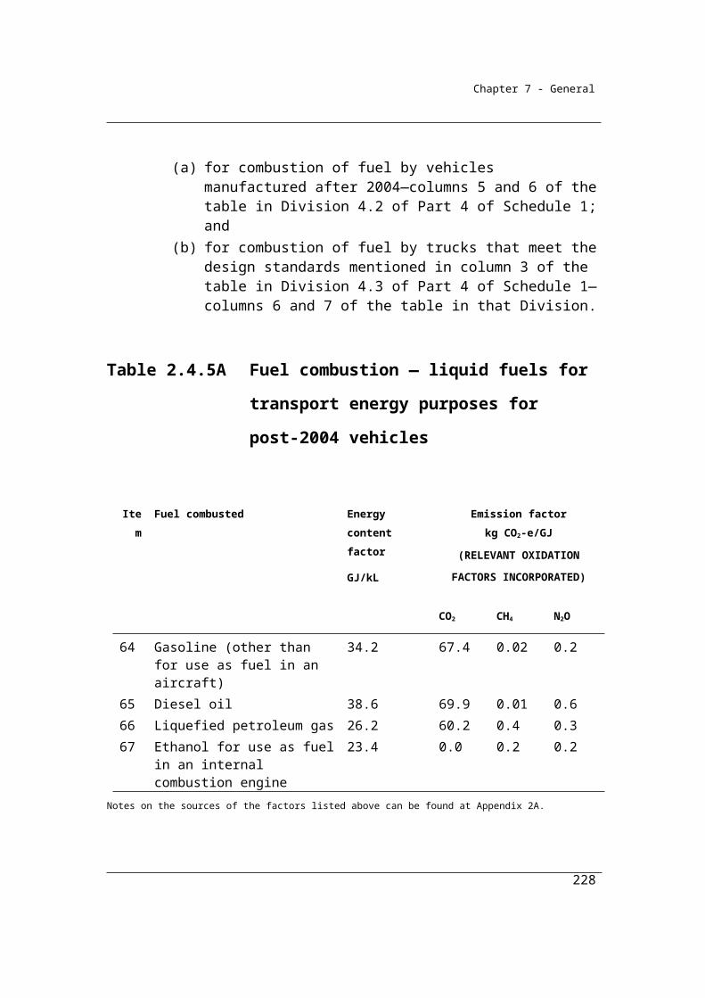
Chapter 7 - General
Summary of available methods for estimating emissions from open cut mines, by emissions of gas type (j)
CO2 CH4 N2O
Open cut mining activities
Method 1 NA Section 3.20 NO
Method 2 Section 3.21 Section 3.21 NO
Method 3 Section 3.26 Section 3.26 NO
Method 4 NA NA NO
Flaring
Method 1 Section 3.27 Section 3.27 Section 3.27
Method 2 Section 3.28 NA NA
Method 3 Section 3.29 NA NA
Method 4 NA NA NA
Venting
Methods 1, 2 and 3 NA NA NO
Method 4 Part 1.3 Part 1.3 NO
NA = Not available. NO = Not occurring
Subdivision 3.2.3.2—Fugitive emissions from extraction of coal
Method 1 for open cut mining operations associated with the extraction of coal is derived from the National Greenhouse Account national methodology as published in the National Inventory Report. Emissions are estimated for a particular location of the
228

Chapter 7 - General
mine by multiplying a (physical) quantity of run-of-mine coal extracted by an emission factor.
3.20 Method 1—extraction of coal
For paragraph 3.19(2)(a), method 1 is:
j jE = Q EF
where:
Ej is the fugitive emissions of methane (j) that result from the extraction of coal from the mine during the year measured in CO2-e tonnes.
Q is the quantity of run-of-mine coal extracted from the mine during the year measured in tonnes.
EFj is the emission factor for methane (j), measured in CO2-e tonnes per tonne of run-of-mine coal extracted from the mine, taken to be the following:
(a) for a mine in New South Wales—0.054;(b) for a mine in Victoria—0.00027;(c) for a mine in Queensland—0.020;(d) for a mine in Western Australia—0.020;(e) for a mine in South Australia—0.00027;(f) for a mine in Tasmania—0.017.
Example
A facility constituted by an open cut coal mine in NSW extracts 2,554,000 tonnes of run-of-
mine coal during the year. The Reporter elects to use Method 1 (Section 3.20) to estimate
fugitive emissions of methane. Emissions are estimated as follows:
where:
229
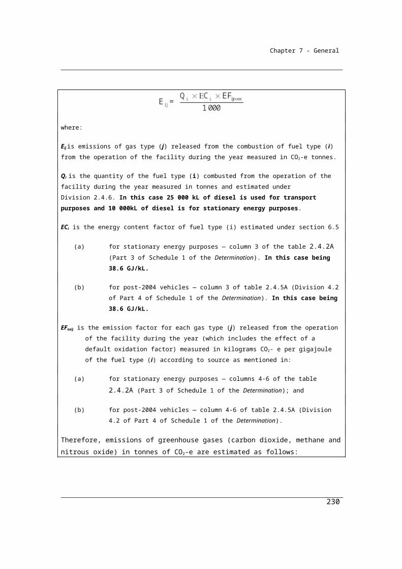
Chapter 7 - General
Ej is the emissions of methane (j) released from the extraction of coal from the mine during
the year, measured in CO2-e tonnes.
Q is the quantity of run-of-mine coal extracted from the mine during the year, measured in
tonnes. In this case being 2,554,000 tonnes of raw coal.
EFj is the emission factor for methane (j), measured in CO2 e tonnes per tonne of raw coal
extracted from the mine. In this case, for an open cut mine in NSW the emission factor is
0.045 tonnes CO2-e per tonne of raw coal extracted.
Therefore, the estimate of methane emissions in CO2-e tonnes:
Ej = (2,554,000 x 0.045)
Total emissions of methane = 114,930 t CO2-e
3.21 Method 2—extraction of coal
Method 2 for estimating emissions from open cut mining requires the estimation of the total in-situ stock of gas held within the mine’s gas bearing strata.
The framework for the method is based on the following ACARP project:
Saghafi, A. (2008), Evaluating a tier 3 method for estimating fugitive emissions from open cut mining, Joint Research Project ACARP (C15076) and CSIRO. CSIRO Investigation Report ET/IR 1011. This report can be obtained from: http://www.acarp.com.au/reports.aspx.
230

Chapter 7 - General
To facilitate the practical application of Method 2/3, an elaboration of the method through amendments to the Determination were introduced for the 2012/13 reporting year.
In parallel to these latest amendments, ACARP published an industry guideline on December 2011 as Project C20005: Guidelines for the Implementation of NGER Method 2 or 3 for Open Cut Coal Mine Fugitive GHG Emissions Reporting. The document contains guidance for the measurement, estimation and reporting of fugitive emissions from open cut mines and is available at: www.acarp.com.au/abstracts.aspx?repId=C20005
The Determination amendments incorporate the ACARP guidelines through the referencing of specific sections of the guidelines. The ACARP Guidelines should be read in conjunction with the Determination. In cases of apparent inconsistency between the ACARP Guidelines and the Determination, the Determination takes precedence.
The Technical Guidelines have been updated to include the amendments to open cut mine methods 2/3. Key changes include:
The introduction of a low gas zone approach, for which methods for defining a low gas zone and an emission factor are provided.
The introduction of the Estimator, along with setting minimum qualification for the Estimator.
Guidance on sampling, analysis, data validation and gas distribution modelling are provided through references within the Determination to relevant sections of the ACARP Guidelines.
A number of new definitions were introduced as part of the set of amendments associated with the elaboration of methods 2/3 for open cut mines. Definitions are listed in section 1.8 of the Determination. Those related to methods 2/3 for open cut mines include the following;
ACARP Guidelines means the document entitled Guidelines for the Implementation of NGER Method 2 or 3 for Open Cut Coal Mine Fugitive GHG Emissions Reporting (C20005), published by the Australian Coal Association Research Program in December 2011.
231

Chapter 7 - General
base of the low gas zone means the part of the low gas zone worked out in accordance with section 3.25A.
domain, of an open cut mine, means an area, volume or coal seam in which the variability of gas content and the variability of gas composition in the open cut mine have a consistent relationship with other geological, geophysical or spatial parameters located in the area, volume or coal seam.
estimator, of fugitive emissions from an open cut mine using method 2 under section 3.21 or method 3 under section 3.26, means:(a) an individual who has the minimum qualifications of an estimator set
out in the ACARP Guidelines; or(b) individuals who jointly have those minimum qualifications.
gas bearing strata is coal and carbonaceous rock strata:(a) located in an open cut mine; and(b) that has a relative density of less than 1.95 g/cm3.
low gas zone means the part of the gas bearing strata of an open cut mine:(a) that is located immediately below the original surface of the mine and
above the base of the low gas zone; and(b) the area of which is worked out by working out the base of the low gas
zone.open cut mine:(a) means a mine in which the overburden is removed from coal seams to
allow coal extraction by mining that is not underground mining; and(b) for method 2 in section 3.21 or method 3 in section 3.26—includes a
mine of the kind mentioned in paragraph (a):(i) for which an area has been established but coal production has
not commenced; or(ii) in which coal production has commenced.
(1) For paragraph 3.19(2)(b) and subsection 3.19(3), method 2 is:
j j z j,zE = S
232
Chapter 7 - General
where:
Ej is the fugitive emissions of gas type (j) that result from the extraction of coal from the mine during the year, measured in CO2-e tonnes.
γj is the factor for converting a quantity of gas type (j) from cubic metres at standard conditions of pressure and temperature to CO2-e tonnes, as follows:
(a) for methane—6.784 × 10-4 × 25;(b) for carbon dioxide—1.861 × 10⁻³.
∑z (Sj,z) is the total of gas type (j) in all gas bearing strata (z) under the extraction area of the mine during the year, measured in cubic metres, where the gas in each strata is estimated under section 3.22.
(2) Method 2 requires each gas in a gas bearing strata to be sampled and analysed in accordance with the requirements in sections 3.24, 3.25 and 3.25A.
3.22 Total gas contained by gas bearing strata
(1) For method 2 under subsection 3.21(1), Sj,z for gas type (j) contained in a gas bearing strata (z) under the extraction area of the mine during the year, measured in cubic metres, is:
jz z z jz t ij, cap,z t ij,flared,z t ijtr t j,vented,zS = M β GC Q Q Q E
where:
Mz is the mass of the gas bearing strata (z) under the extraction area of the mine during the year, measured in tonnes.
βz is the proportion of the gas content of the gas bearing strata (z) that is released by extracting coal from the extraction area of the mine during the year, as follows:
(a) if the gas bearing strata is at or above the pit floor—1;(b) in any other case—as estimated under section 3.23.
GCjz is the content of gas type (j) contained by the gas bearing strata (z) before gas capture, flaring or venting is undertaken at the extraction area of the mine during the year, measured in cubic metres per tonne of gas bearing strata at standard conditions.
∑Qij,cap,z is the total quantity of gas type (j) in coal mine waste gas (i) captured for combustion from the gas bearing strata (z) at any time before
233
Chapter 7 - General
coal is extracted from the extraction area of the mine during the year, measured in cubic metres.
∑Qij,flared,z is the total quantity of gas type (j) in coal mine waste gas (i) flared from the gas bearing strata (z) at any time before coal is extracted from the extraction area of the mine during the year, measured in cubic metres.
∑Qijtr is the total quantity of gas type (j) in coal mine waste gas (i) transferred out of the mining activities at any time before coal is extracted from the extraction area of the mine during the year, measured in cubic metres.
∑Ej,vented,z is the total emissions of gas type (j) vented from the gas bearing strata (z) at any time before coal is extracted from the extraction area of the mine during the year, measured in cubic metres and estimated under subsection 3.19 (6).
(2) For ∑Qij,cap,z, ∑Qij,flared,z and ∑Qijtr in subsection (1), the quantity of gas type (j) must be estimated in accordance with Division 2.3.6 as if a reference in that Division to quantities of gaseous fuels combusted from the operation of a facility was a reference to the following:
(a) for ∑Qij,cap,z—quantities of gaseous fuels captured from the operation of a facility;
(b) for ∑tQij,flared,z—quantities of gaseous fuels flared from the operation of a facility;
(c) for ∑Qijtr—quantities of gaseous fuels transferred out of the operation of a facility.
(3) In subsection (1), ∑Qijtr applies to carbon dioxide only if the carbon dioxide is captured for permanent storage.Note: Division 1.2.3 contains a number of requirements in relation to deductions of
carbon dioxide captured for permanent storage.
(4) For GCjz in subsection (1), the content of gas type (j) contained by the gas bearing strata (z) must be estimated in accordance with sections 3.24, 3.25, 3.25A and 3.25B.
3.23 Estimate of proportion of gas content released below pit floor
For paragraph (b) of the factor βz in subsection 3.22(1), estimate βz using one of the following equations:
(a) equation 1:
234

Chapter 7 - General
zx h 1
dh
;
(b) equation 2:
z 0.5 .
where:
x is the depth in metres of the floor of the gas bearing strata (z) measured from ground level.
h is the depth in metres of the pit floor of the mine measured from ground level.
dh is 20, being representative of the depth in metres of the gas bearing strata below the pit floor that releases gas.
3.24 General requirements for sampling
(1) Core samples of a gas bearing strata must be collected to produce estimates of gas content that are representative of the gas bearing strata in the extraction area of the mine during the year.
(2) The sampling process must also be free of bias so that any estimates are neither over nor under estimates of the true value.
(3) Bias must be tested in accordance with an appropriate standard (if any).
(4) The value obtained from the samples must only be used for the open cut mine from which it was intended to be representative.
(5) Sampling must be carried out in accordance with:(a) the minimum requirements for data collection and gas testing
mentioned in section 2 of the ACARP Guidelines; and(b) the data validation, analysis and interpretation processes mentioned
in section 3 of the ACARP Guidelines.
3.25 General requirements for analysis of gas and gas bearing strata
Measurement of the gas content from coal and other gas bearing strata layers requires use of borecores. Geological characteristics can help to identify possible gas bearing areas based on previous evidence of gas content in a region and to infer gas content of coal and rock strata between actual borecore measurements. However
235

Chapter 7 - General
knowledge of geological characteristics of a site, with no specific borecore measurements, would not be able to adequately predict gas content (Saghafi, 2008).
Analysis of a gas and a gas bearing strata, including the mass and gas content of the strata, must be done in accordance with:
(a) the minimum requirements for data collection and gas testing mentioned in section 2 of the ACARP Guidelines; and
(b) the data validation, analysis and interpretation processes mentioned in section 3 of the ACARP Guidelines; and
(c) the method of applying the gas distribution model to develop an emissions estimate for an open cut mine mentioned in section 4 of the ACARP Guidelines.
3.25A Method of working out base of the low gas zone
(1) The estimator must:(a) take all reasonable steps to ensure that samples of gas taken from the
gas bearing strata of the open cut mine are taken in accordance with the minimum requirements for data collection and gas testing mentioned in section 2 of the ACARP Guidelines; and
(b) take all reasonable steps to ensure that samples of gas taken from boreholes are taken in accordance with the requirements for:(i) the number of boreholes mentioned in sections 2 and 3 of the
ACARP Guidelines; and(ii) borehole spacing mentioned in section 2 of the ACARP
Guidelines; and(iii) sample selection mentioned in section 2 of the ACARP
Guidelines; and(c) work out the base of the low gas zone by using the method
mentioned in subsection (2); and(d) if the base of the low gas zone worked out in accordance with
subsection (2) varies, in a vertical plane, within:(i) a range of 20 metres between boreholes located in the same
domain of the open cut mine—work out the base of the low gas zone using the method mentioned in subsection (3); or
(ii) a range of greater than 20 metres between boreholes located in the same domain of the open cut mine—the method mentioned in subsection (4).
236
Chapter 7 - General
Preliminary method of working out base of low gas zone
(2) For paragraph (1)(c), the method is that the estimator must perform the following steps:
Step 1 For each borehole, identify the depth at which:(a) the results of greater than 3 consecutive samples taken in the
borehole indicate that the gas content of the gas bearing strata is greater than 0.5 m3/t; or
(b) the results of 3 consecutive samples taken in the borehole indicate that the methane composition of the gas bearing strata is greater than 50% of total gas composition by volume.
Step 2 If paragraph (a) or (b) of step 1 applies, identify, for each borehole, the depth of the top of the gas bearing strata at which the first of the 3 consecutive samples in the borehole was taken.Note The depth of the top of the gas bearing strata worked out
under step 2 is the same as the depth of the base of the low gas
zone.
Method of working out base of low gas zone for subparagraph (1)(d)(i)
(3) For subparagraph (1)(d)(i), the method is that the estimator must work out the average depth at which step 2 of the method in subsection (2) applies.
Method of working out base of low gas zone for subparagraph (1)(d)(ii)
(4) For subparagraph (1)(d)(ii), the method is that the estimator must construct a 3-dimensional model of the surface of the low gas zone using a triangulation algorithm or a gridding algorithm.
3.25B Further requirements for estimator
(1) This section applies if:(a) the estimator constructs a 3-dimensional model of the surface of the
base of the low gas zone in accordance with the method mentioned in subsection 3.25A(4); and
(b) the 3-dimensional model of the surface of the low gas zone is extrapolated beyond the area modelled directly from boreholes in the domain.
(2) The estimator must:(a) ensure that the extrapolated surface:
237
Chapter 7 - General
(i) applies the same geological modelling rules that were applied in the generation of the surface of the base of the low gas zone from the boreholes; and
(ii) represents the base of the low gas zone in relation to the geological structures located within the domain; and
(iii) is generated using a modelling methodology that is consistent with the geological model used to estimate the coal resource; and
(iv) the geological model used to estimate the coal resource meets the minimum requirements and the standard of quality mentioned in section 1 of the ACARP Guidelines.
(b) make and retain a record:(i) of the data and assumptions incorporated into the generation of
the 3-dimensional surface; and(ii) that demonstrates that the delineation of the 3-dimensional
surface complies with sections 1.13 and 3.24.
3.25C Default gas content for gas bearing strata in low gas zone
A default gas content of 0.00023 tonnes of carbon dioxide per tonne of gas bearing strata must be assigned to all gas bearing strata located in the low gas zone.
3.25D Requirements for estimating total gas contained in gas bearing strata
(1) The total gas contained in gas bearing strata for an open cut coal mine must be estimated in accordance with the emissions estimation process mentioned in section 1 of the ACARP Guidelines.
(2) The gas distribution model used for estimating emissions must be applied in accordance with section 4.1 of the ACARP Guidelines; and
(3) The modelling bias must be assessed in accordance with section 4.2 of the ACARP Guidelines.
(4) The gas distribution model must be applied to the geology model in accordance with section 4.3 of the ACARP Guidelines.
3.26 Method 3—extraction of coal
(1) For paragraph 3.19(2)(c) and subsection 3.19(4), method 3 is the same as method 2 under section 3.21
238
Chapter 7 - General
(2) In applying method 2 under section 3.21 a sample of gas bearing strata must be collected in accordance with an appropriate standard, including:
(a) AS 2617—1996 Sampling from coal seams or an equivalent standard; and
(b) AS 2519—1993 Guide to the technical evaluation of higher rank coal deposits or an equivalent standard.
Subdivision 3.2.3.3—Emissions released from coal mine waste gas flared
3.27 Method 1—coal mine waste gas flared
(1) For subparagraph 3.19(5)(a)(i) and paragraph 3.19(5)(b) and paragraph (5)(c), method 1 is the same as method 1 under section 3.14.
(2) In applying method 1 under section 3.14, a reference to an underground mine is taken to be a reference to an open cut mine.
3.28 Method 2—coal mine waste gas flared
Method 2 is the same as method 2 under section 3.15. Method 2 requires representative and unbiased samples of coal mine waste gas consumed and analysis of the coal mine waste gas to determine gas composition and must be done in accordance with Australian or equivalent international standards and as set out for Division 2.3.3
For subparagraph 3.19(5)(a)(ii), method 2 is the same as method 2 under section 3.15.
3.29 Method 3—coal mine waste gas flared
Method 3 is the same as for Method 2 except that it requires samples to be obtained in accordance with Australian or equivalent international standards and as set out in Division 2.3.4.
For subparagraph 3.19(5)(a)(iii), method 3 is the same as method 3 under section 3.16.
239
Chapter 7 - General
Division 3.2.4—Decommissioned underground minesGreenhouse gas emissions are known to occur following the closure of coal mines. Leakages to the atmosphere occur through fractured rock strata, open vents and seals over daily to decadal timescales. However, emissions will be reduced by flooding of the mine, which prevents desorption of gases from the remaining coal strata and non-coal strata layers in the closed mine.
Subdivision 3.2.4.1—Preliminary
3.30 Application
This Division applies to fugitive emissions from decommissioned underground mines that have been closed for a continuous period of at least 1 year but less than 20 years.
3.31 Available methods
(1) Subject to section 1.18, for estimating emissions released during a year from the operation of a facility that is constituted by a decommissioned underground mine that has been closed for a continuous period of at least 1 year but less than 20 years the methods as set out in this section must be used.
Methane from decommissioned mines
(2) One of the following methods must be used for estimating fugitive emissions of methane that result from the mine:
(a) subject to subsection (6), method 1 under section 3.32;(b) method 4 under section 3.37.
Note: There is no method 2 or 3 for subsection (2).
Carbon dioxide from decommissioned mines
(3) If method 4 under section 3.37 is used under subsection (2), that method must be used for estimating fugitive emissions of carbon dioxide that result from the mine.Note: There is no method 1, 2 or 3 for subsection (3).
240
Chapter 7 - General
Flaring
(4) For estimating emissions released from coal mine waste gas flared from the mine:
(a) one of the following methods must be used for estimating emissions of carbon dioxide released:(i) method 1 under section 3.38;
(ii) method 2 under section 3.39;(iii) method 3 under section 3.40; and
(b) method 1 under section 3.38 must be used for estimating emissions of methane released.
(c) method 1 under section 3.38 must be used for estimating emissions of nitrous oxide released.
Note: The flaring of coal mine waste gas releases emissions of carbon dioxide, methane and nitrous oxide. The same formula is used to estimate emissions of each of these gases. There is no method 4 for emissions of carbon dioxide, no method 2, 3 or 4 for emissions of methane and no method 2, 3 or 4 for nitrous oxide.
(5) However, for incidental emissions another method may be used that is consistent with the principles in section 1.13.
(6) If coal mine waste gas from the decommissioned underground mine is captured for combustion during the year, method 1 in subsection (2) must not be used.
241

Chapter 7 - General
Summary of available methods for estimating emissions from decommissioned mines, by emissions of gas type (j)
CO2 CH4 N2O
Underground decommissioned mines
Method 1 NA Section 3.32 NO
Methods 2, 3 NA NA NO
Method 4 Section 3.37 Section 3.37 NO
Flaring
Method 1 Section 3.38 Section 3.38 Section 3.38
Method 2 Section 3.39 NA NA
Method 3 Section 3.40 NA NA
Method 4 NA NA NA
NA = Not available. NO = Not occurring
Subdivision 3.2.4.2—Fugitive emissions from decommissioned underground mines
Method 1 for emissions from decommissioned mines is derived from the National Greenhouse Account national methodology as published in the National Inventory Report.
3.32 Method 1—decommissioned underground mines
(1) For paragraph 3.31(2)(a), method 1 is:
dm tdm dm dmE = E EF (1 F )[ ]
where:
Edm is the fugitive emissions of methane from the mine during the year measured in CO2-e tonnes.
242

Chapter 7 - General
Etdm is the emissions from the mine for the last full year that the mine was in operation measured in CO2-e tonnes and estimated under section 3.5 or 3.6.
EFdm is the emission factor for the mine calculated under section 3.33.
Fdm is the proportion of the mine flooded at the end of the year, as estimated under section 3.34, and must not be greater than 1.
(2) However, if, under subsection (1), the estimated emissions in CO2-e tonnes for the mine during the year is less than 0.02 Etdm, the estimated emissions for the mine during the year is taken to be 0.02 Etdm.
3.33 Emission factor for decommissioned underground mines
The emission factor for Method 1 is derived from an emission decay curve (EDC). The EDC describes the decline in fugitive methane emissions overtime following mine closure. Hyperbolic curves have been found to function best in portraying the rapid decline in emissions in the first few years, followed by a slow decline over time of the remaining emissions (National Inventory Report).
Australian-specific EDCs developed for the national inventory have being utilized for both gassy and non-gassy mines.
For section 3.32, EFdm is the integral under the curve of:b(1 + A Τ) C
for the period between T and T-1,where:
A is:(a) for a gassy mine—0.23; or(b) for a non-gassy mine—0.35.
T is the number of years since the mine was decommissioned.
b is:(a) for a gassy mine—-1.45; or(b) for a non-gassy mine—-1.01.
C is:(a) for a gassy mine—0.024; or
243
Chapter 7 - General
(b) for a non-gassy mine—0.088.
3.34 Measurement of proportion of mine that is flooded
Emissions from decommissioned mines are reduced as a mine floods due to the reduction of gas desorption from the coal remaining in the closed mine. The variables required to estimate the portion of the mine flooded at a point in time is the size of the void volume and the water inflow rate into the closed mine.
For subsection 3.32(1), Fdm is:
WI
VV
M × yearsM
where:
MWI is the rate of water flow into the mine in cubic metres per year as measured under section 3.35.
MVV is the mine void volume in cubic metres as measured under section 3.36.
years is the number of years since the mine was decommissioned.
3.35 Water flow into mine
For MWI in section 3.34, the rate of water flow into the mine must be measured by:
(a) using water flow rates for the mine estimated in accordance with an appropriate standard; or
(b) using the following average water flow rates:(i) for a mine in the southern coalfield of New South Wales—
913 000 cubic metres per year; or(ii) for a mine in the Newcastle, Hunter, Western or Gunnedah
coalfields in New South Wales—450 000 cubic metres per year; or
(iii) for a mine in Queensland—74 000 cubic metres per year.Note: An appropriate standard includes AS 2519—1993 Guide to the technical
evaluation of higher rank coal deposits.
3.36 Size of mine void volume
For MVV in section 3.34, the size of the mine void volume must be measured by:
244

Chapter 7 - General
(a) using mine void volumes for the mine estimated in accordance with industry practice; or
(b) dividing the total amount of run-of-mine coal extracted from the mine before the mine was decommissioned by 1.425.
3.37 Method 4—decommissioned underground mines
(1) For paragraph 3.31(2)(b) and subsection 3.31(3), method 4 is the same as method 4 in section 3.6.
(2) In applying method 4 under section 3.6, a reference to an underground mine is taken to be a reference to a decommissioned underground mine.
Subdivision 3.2.4.3—Fugitive emissions from coal mine waste gas flared
3.38 Method 1—coal mine waste gas flared
Emissions using Method 1 are estimated by multiplying the quantity of gas flared by the energy content and emission factor for the coal mine waste gas. The quantity of coal mine waste gas flared should be estimated in accordance with Division 2.3.6. The energy content and emission factors are obtained from Division 2.3.2 of Chapter 2.
(1) For subparagraph 3.31(4)(a)(i) and paragraphs 3.31(4)(b) and (4)(c), method 1 is the same as method 1 under section 3.14.
(2) In applying method 1 under section 3.14, a reference to an underground mine is taken to be a reference to a decommissioned underground mine.
3.39 Method 2—coal mine waste gas flared
For subparagraph 3.31(4)(a)(ii), method 2 is the same as method 2 under section 3.15.
3.40 Method 3—coal mine waste gas flared
For subparagraph 3.31(4)(a)(iii), method 3 is the same as method 3 under section 3.16.
245
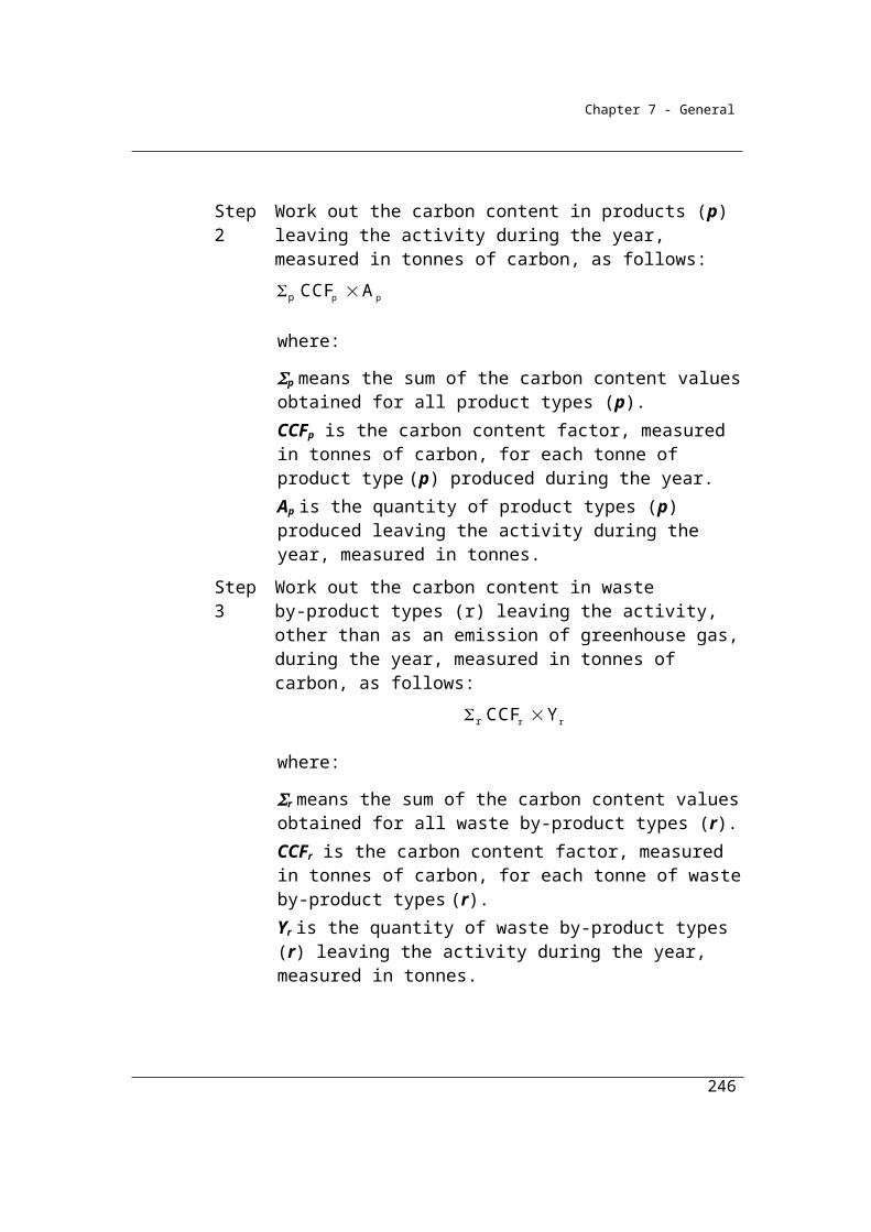
Chapter 7 - General
Part 3.3—Oil and natural gas—fugitive emissions
Division 3.3.1—PreliminaryThis part includes fugitive emissions from exploration, production, transport, storage, processing and refining of oil or gas.
Other sources of emissions arising from the production processes, such as from the combustion of fuels for energy, are not described in this chapter and must be estimated using the Methods described in other chapters.
Fugitive emissions in the oil and gas sector can be largely classified as being either a vent, leak or a flare. A flare involves the combustion of a gas or liquid for a non-energy purpose. The distinction between leaks and vents was derived from the definition used by the American Petroleum Institute Compendium of Greenhouse Gas Emissions Methodologies for the Oil and Natural Gas Industry (API) and was developed for the application for the Determination in consultation with industry.
Vent
Vents are considered to be emissions that are the result of process or equipment design or operational practices; and;
Leak
Leaks are considered to be emissions from unintentional equipment leaks from valves, flanges, pump seals, compressor seals, relief valves, sampling connections, process drains, process drains, open-ended lines, casing, tanks, casing leaks and other leakage sources from pressurised equipment not defined as a vent.
The Determination makes use of methods for estimating emissions from vents and leaks in the API Compendium. Amendments for July1 2012 have updated references from the 2004 API to the 2009 version of the API Compendium. The Determination refers to specific section of API 2009 for methods such as engineering approaches and activity or equipment type factors. Most sections of the API Compendium provide the gas content basis for the emission factors and note that the factors can be adjusted based on site-specific gas composition.
Conversion flared cubic meters to flared tonnes
246
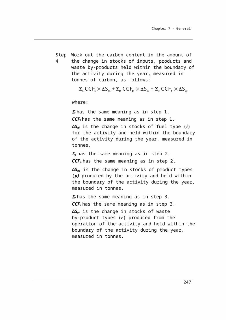
Chapter 7 - General
Depending on the original data units available to reporters, method 1 for estimating emissions from flaring may require a density conversion for the quantity of fuel type flared from cubic metres to tonnes. Rather than the Determination setting a default density, it is considered that the reporter would be best positioned to understand the characteristics of their flared gas stream. Considerable variability would be expected in the density of flare gas depending on plants and processes, and therefore a universal default figure is unlikely to be useful.
To complement the reporters understanding of their flared gas stream, various gas density values are available in national and international literature such as in the API 2009 Compendium or National Pollution Inventory manuals. Conversions are required to be estimated in standard conditions as specified in the Determination in 2.32 (7). Site specific density figures may also be derived using sampling and measurement approaches under section 2.24 of the Determination. Reporters are reminded of that the approach should be consistent with the general principles detailed in Section 1.13 of the Determination.
3.40A Definition of natural gas for Part 3.3
In this Part:
natural gas includes the following:(a) shale gas;(b) tight gas;(c) coal seam methane that is captured for combustion where the
production of coal is not intended to occur.
3.41 Outline of Part
This Part provides for fugitive emissions from the following:(a) oil or gas exploration (see Division 3.3.2);(b) crude oil production (see Division 3.3.3);(c) crude oil transport (see Division 3.3.4);
(d) crude oil refining (see Division 3.3.5);(e) natural gas production or processing, other than emissions that are
vented or flared (see Division 3.3.6);(f) natural gas transmission (see Division 3.3.7);(g) natural gas distribution (see Division 3.3.8);
247
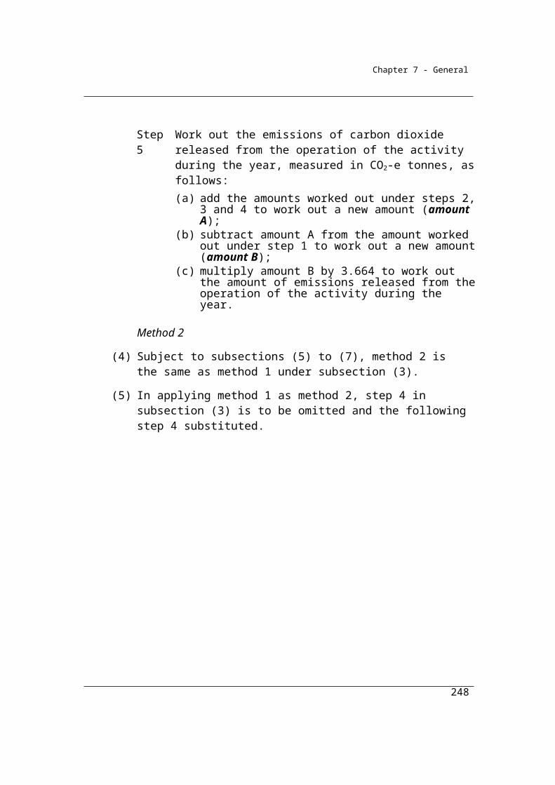
Chapter 7 - General
(h) natural gas production or processing (emissions that are vented or flared) (see Division 3.3.9).
248

Chapter 7 - General
Division 3.3.2—Oil or gas explorationEmissions may occur during the process of drilling for oil or gas either during exploration or development drilling whenever gas or liquid hydrocarbons are encountered. CO2, some unburnt methane and N2O are released as a result of the flaring of oil or gas. Emissions may also occur as a result of venting and accidental releases such as blowouts.
Subdivision 3.3.2.1—Preliminary
3.42 Application
This Division applies to fugitive emissions from venting or flaring from oil or gas exploration activities, including emissions from:
(a) oil well drilling; and(b) gas well drilling; and(c) drill stem testing; and (d) well completions; and(e) wellworkovers.
Subdivision 3.3.2.2—Oil or gas exploration (flared) emissions
3.43 Available methods
Methods 1, 2 and 3 are set out below for the estimation of emissions from flaring of fuel. Flaring is the combustion of fuels for non-productive (non-commercial) reasons –for example for health and safety reasons. Methods 2 and 3 rely on the sampling and analysis of the fuel to estimate the composition of the gases in the fuel in accordance with the provisions of chapter 2.
(1)Subject to section 1.18, for estimating emissions released by oil or gas flaring during the year from the operation of a facility that is constituted by oil or gas exploration:
(a) if estimating emissions of carbon dioxide released—one of the following methods must be used:(i) method 1 under section 3.44;
(ii) method 2 under section 3.45;(iii) method 3 under section 3.46; and
249

Chapter 7 - General
(b) if estimating emissions of methane released—one of the following methods must be used:(i) method 1 under section 3.44;
(ii) method 2A under section 3.45A; and(c) if estimating emissions of nitrous oxide released—one of the
following methods must be used:(i) method 1 under section 3.44;
(ii) method 2A under section 3.45A.Note: There is no method 4 under paragraph (a) and no method 2, 3 or 4 under
paragraph (b) or (c).
(2) However, for incidental emissions another method may be used that is consistent with the principles in section 1.13.
Summary of available methods, for estimating flaring emissions from oil and gas exploration, by emissions of gas type (j)
CO2 CH4 N2O
Method 1 Section 3.44 Section 3.44 Section 3.44
Method 2 Section 3.45 NA NA
Method 3 Section 3.46 NA NA
Method 4 NA NA NA
NA = Not available.
3.44 Method 1—oil or gas exploration
Method 1 for oil exploration and gas exploration is derived from the National Greenhouse Accounts.
(1)Method 1 is:
ij i ijE = Q EF
where:
Eij is the fugitive emissions of gas type (j) from a fuel type (i) flared in the oil or gas exploration during the year measured in CO2-e tonnes.
250

Chapter 7 - General
Qi is the quantity of fuel type (i) flared in the oil or gas exploration during the year measured in tonnes.
EFij is the emission factor for gas type (j) measured in tonnes of CO2-e emissions per tonne of the fuel type (i) flared.
(2) For EFij in subsection (1), columns 3, 4 and 5 of an item in the following table specify the emission factor, for gas type (j), for each fuel type (i) specified in column 2 of that item.
Item Fuel type (i) Emission factor for gas type (j) (tonnes CO2-e/tonnes of fuel flared)CO2 CH4 N2O
1 Unprocessed gas flared 2.8 0.8 0.032 Crude oil 3.2 0.008 0.07
3.45 Method 2—oil or gas exploration (flared carbon dioxide emissions)
Combustion of gaseous fuels (flared) emissions
(1) For subparagraph 3.43(1)(a)(ii), method 2 for combustion of gaseous fuels is:
i 22ico h h OF QCOE Q EF
where:
EiCO2 is the fugitive emissions of CO2 from fuel type (i) flared in oil or gas exploration during the year, measured in CO2-e tonnes.
Qh is the total quantity of hydrocarbons (h) within the fuel type (i) in oil or gas exploration during the year, measured in tonnes in accordance with Division 2.3.3.
EFh is the emission factor for the total hydrocarbons (h) within the fuel type (i) in oil or gas exploration during the year, measured in CO2-e tonnes per tonne of the fuel type (i) flared, estimated in accordance with Division 2.3.3.
OFi is 0.98, which is the destruction efficiency of fuel type (i) flared.
QCO2 is the quantity of CO2 within fuel type (i) in oil or gas exploration during the year, measured in CO2-e tonnes in accordance with Division 2.3.3.
251
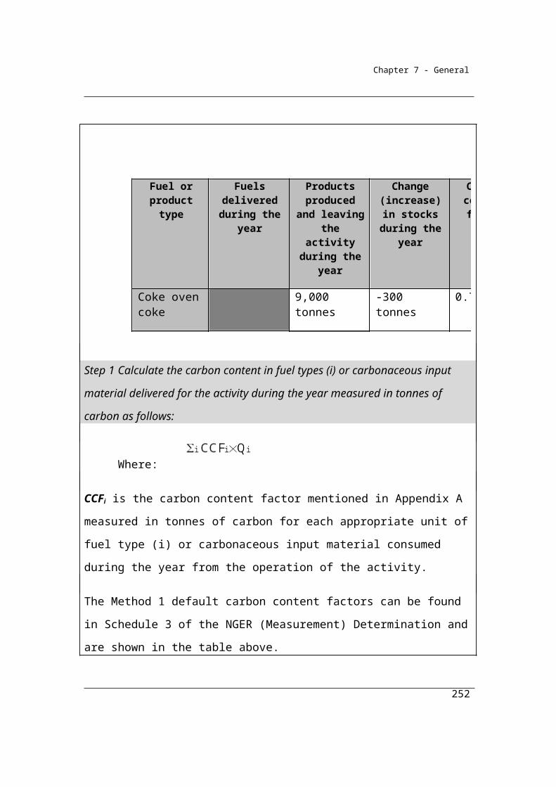
Chapter 7 - General
Combustion of liquid fuels (flared) emissions
(2) For subparagraph 3.43(1)(a)(ii), method 2 for combustion of liquid fuels is the same as method 1 under section 3.44, but the carbon dioxide emissions factor EFij must be determined in accordance with method 2 in Division 2.4.3.
3.45A Method 2A—oil or gas exploration (flared methane or nitrous oxide emissions)
For subparagraphs 3.43(1)(b)(ii) and (c)(ii), method 2A is:
where:
EFhij is the emission factor of gas type (j), being methane or nitrous oxide, for the total hydrocarbons (h) within the fuel type (i) in oil or gas exploration during the year, mentioned for the fuel type in the table in subsection 3.44(2) and measured in CO2-e tonnes per tonne of the fuel type (i) flared.
Eij is the fugitive emissions of gas type (j), being methane or nitrous oxide, from fuel type (i) flared from oil or gas exploration during the year, measured in CO2-e tonnes.
OFi is 0.98, which is the destruction efficiency of fuel type (i) flared.
Qh is the total quantity of hydrocarbons (h) within the fuel type (i) in oil or gas exploration during the year, measured in tonnes in accordance with Division 2.3.3 for gaseous fuels or Division 2.4.3 for liquid fuels.
3.46 Method 3—oil or gas exploration
Combustion of gaseous fuels (flared) emissions
(1) For subparagraph 3.43(1)(a)(iii), method 3 for the combustion of gaseous fuels is the same as method 2, but the carbon dioxide emissions factor EFh must be determined in accordance with method 3 in Division 2.3.4.
Combustion of liquid fuels (flared) emissions
(2) For subparagraph 3.43(1)(a)(iii), method 3 for the combustion of liquid fuels is the same as method 2, but the carbon dioxide emissions factor EFh must be determined in accordance with method 3 in Division 2.4.4.
252
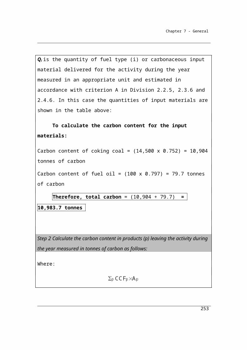
Chapter 7 - General
Subdivision 3.3.2.3—Oil or gas exploration—fugitive emissions from system upsets, accidents and deliberate releases from process vents
3.46A Available methods
(1) Subject to section 1.18, the methods mentioned in subsections (2) and (3) must be used for estimating fugitive emissions that result from system upsets, accidents and deliberate releases from process vents during a reporting year from the operation of a facility that is constituted by oil or gas exploration.
(2) To estimate emissions that result from deliberate releases from process vents, systems upsets and accidents at a facility during a year, for each oil or gas exploration activity one of the following methods must be used:
(a) method 1 under section 3.84;(b) method 4 under:
(i) for emissions of methane and carbon dioxide from natural gas well completions or well workover activities—section 3.46B; or
(ii) for emissions and activities not mentioned in subparagraph (i)—Part 1.3.
(3) For estimating incidental emissions that result from deliberate releases from process vents, system upsets and accidents during a year from the operation of the facility, another method may be used that is consistent with the principles mentioned in section 1.13.Note: There is no method 2 or 3 for this Subdivision.
3.46B Method 4—vented emissions from well completions and well workovers
Vented volume measured for all wells and well types in a basinAn optional method 4 has been introduced for estimating vented methane and
carbon dioxide emissions from coal seam gas well completions and
workovers. Two approaches are provided:
1) Vented volume measured for all wells and well types in a basin;
where all vented volumes for well completions or workover are
measured for all well types(vertical and horizontal); and
253
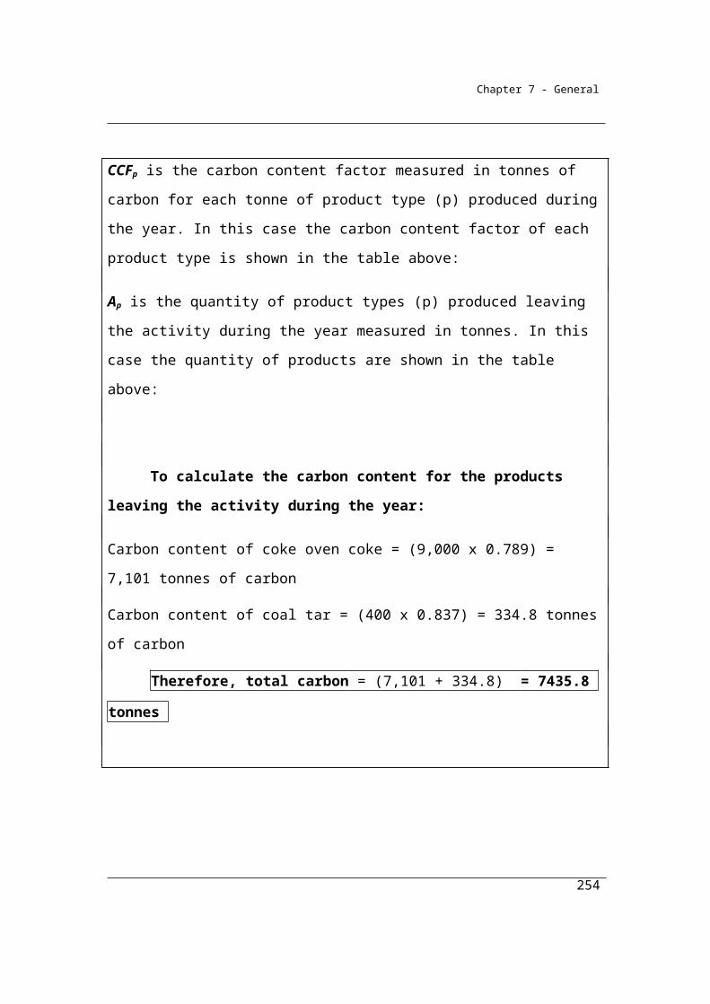
Chapter 7 - General
2) Vented volume measured for a sample of wells and well types in a
basin;
where the total emissions for well completions or workovers are
estimated based on the measurement of flow rate taken from a
sample of the well population during the year.
Conversion to standard conditions
All gas volumes are to be converted to standard conditions as set out in
2.32(7).
Measurement of gaseous quantities.
Division 2.3.6 sets out requirements for the measurement of gaseous
quantities, including criterion BBB - estimation in accordance with industry
practice).
Vented volume measured for all wells and well types in a basin
Emissions arising from both strata and gas injected for each well are summed
and converted to carbon dioxide equivalents in subsection (1).
The volume of methane vented from the strata for each well (ESp) is
estimated in subsection (2). Methane volume from strata is estimated by
subtracting the volume of gas measured on the vent line from the any
volumes of gas injected during a completion or workover. This approach
assumes that gas volumes from strata are methane and therefore gas
compositional analysis under Division 2.3.3 is not required.
The volume of any injected methane and carbon dioxide (VIGG jp) is
estimated in subsection (3). Compositional analysis of the gas under Division
2.3.3 is required to separate methane and carbon dioxide components of the
injected gas.
(1) For subparagraph 3.46A(2)(b)(i), where vented volume is measured for all wells and well types (horizontal or vertical) in a basin, method 4 is:
254
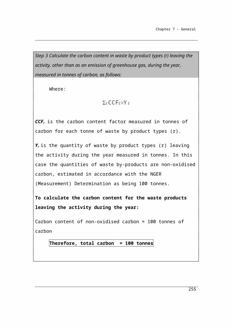
Chapter 7 - General
where:
Emj is total emissions for gas type (j), being methane and carbon dioxide from all well completions and well workovers during a year in a basin, measured in CO2-e tonnes.
ESp is the volume of methane vented during a well completion or well workover from strata for each well (p) in cubic metres at standard conditions, worked out in accordance with subsection (2).
VIGGj,p is the volume of gas type (j) in cubic metres at standard conditions, being methane and carbon dioxide, injected into the well during well completion or well workover, worked out in accordance with subsection (3).
W is the total number of well completions and well workovers in the basin during a year.
γj is the factor for converting a quantity of gas type (j) from cubic metres at standard conditions to CO2-e tonnes, being:
(a) for methane—6.784 × 10-4 × 25; and(b) for carbon dioxide—1.861 × 10⁻³.
Z is the total number of greenhouse gas types.
(2) For subsection (1), the factor ESp is worked out using the formula:
where:
FVp is the flow volume of each well (p) in cubic metres at standard conditions, measured using a digital or analog recording flow metre on the vent line to measure flowback during the well completion or well workover, estimated in accordance with Division 2.3.6.
VIp is the volume of injected gas in cubic metres at standard conditions that is injected into the well during the well completion or well workover, estimated in accordance with Division 2.3.6.
(3) For subsection (1), VIGGj,p is worked out using the following formula:
where:
255
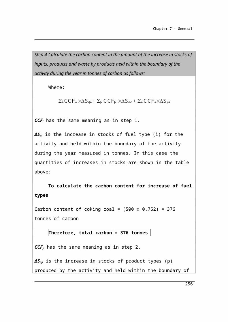
Chapter 7 - General
molj,p%, for each gas type (j), being methane and carbon dioxide, is the gas type’s share of one mole of VIp expressed as a percentage, estimated in accordance with Division 2.3.3.
VIp is the volume of injected gas in cubic metres at standard conditions that is injected into the well during the well completion or well workover, estimated in accordance with Division 2.3.6.
Vented volume measured for a sample of wells and well types in a basin
Vented volume measured for a sample of wells and well types in a basin
The vented volume is estimated in subsection (4) by using a sampling
approach, where a subset of all the well completions/workers, by well
type, are sampled during the year for a basin. Subsection (8) sets out
the well sampling requirements where, for well completions or
workovers, a minimum of 10% of all well types in a basin are to be
sampled.
Measurement is required of the flow rate for both the flowback and the
first 30 day production, in accordance with Division 2.3.6, to derive
average flow rates. These average flow rates are used in subsection
(7) to derive the ratio of flowback to 30 day production rate (FRMbt) for
each well type sampled.
In subsection (5), the ratio (FRMbt) is extrapolated to all respective well
completion/workovers in the basin during the year to give EVp, being
the estimated volume of methane flowback during well
completions/workovers from strata, for each well.
Subection (4) estimates net vented emissions for each well by allowing
for the subtraction of captured or flared gas type volumes and the
addition of gas volume types injected, before finally summing emission
net emissions across all wells.
256
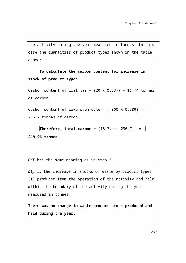
Chapter 7 - General
(4) For subparagraph 3.46A(2)(b)(i), where vented volume is measured for a sample of wells and well types (horizontal or vertical) in a basin, method 4 is:
where:
Emj is total emissions for gas type (j), being methane and carbon dioxide from all well completions and well workovers during a year in a basin, measured in CO2-e tonnes.
EVp is the volume of methane flowback during a well completion or well workover from strata for each well (p) in cubic metres at standard conditions, worked out in accordance with subsection (5).
SGj,p is the volume of gas type (j), being methane and carbon dioxide, in cubic metres at standard conditions that is captured or flared for each well (p) during the well completion or well workover, estimated in accordance with:
(a) for the volume of the gas—Division 2.3.6; and(b) for the gas composition—Division 2.3.3.
VIGGj,p is the volume of gas type (j), being methane and carbon dioxide, injected into each well (p) during the well completion or well workover, worked out in accordance with subsection (6).
W is the total number of well completions and well workovers during a year in the basin.
γj is the factor for converting a quantity of gas type (j) from cubic metres at standard conditions to CO2-e tonnes, being:
(a) for methane—6.784 × 10-4 × 25; and(b) for carbon dioxide—1.861 × 10⁻³.
Z is the total number of greenhouse gas types.
(5) For subsection (4), the factor EVp is worked out using the following formula:
where:
257
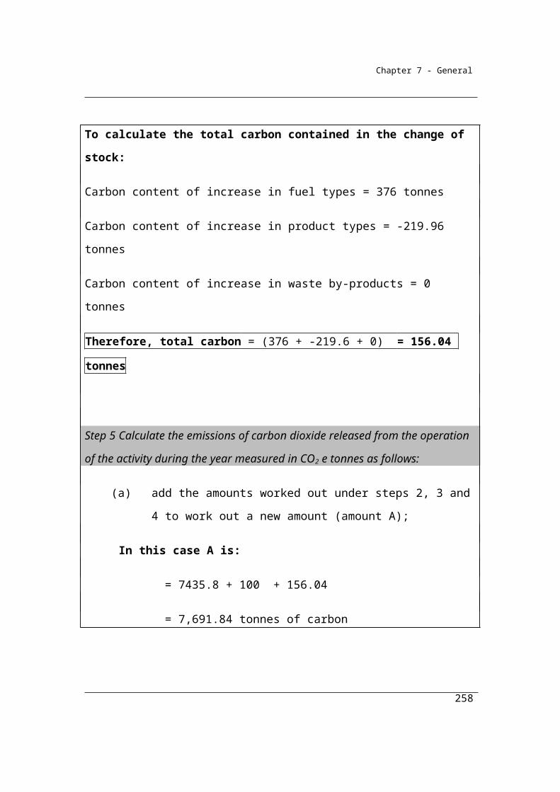
Chapter 7 - General
FRMbt is the ratio of flowback during well completions and well workovers to the 30 day production rate for the basin (b) and the well type combination (t), as worked out in accordance with subsection (7).
PRp is the first 30 days average production flow rate in cubic metres per hour at each well (p), estimated in accordance with Division 2.3.6.
Tp is the total number of hours for the reporting year of flowback for the well completion or well workover for each well (p) and well type (horizontal or vertical) in a basin.
VIp is the volume of injected gas in cubic metres at standard conditions that is injected into the well during the well completion or well workover, estimated in accordance with Division 2.3.6.
(6) For subsection (4), VIGGj,p is worked out using the following formula:
where:
molj,p%, for each gas type (j), being methane and carbon dioxide, is the gas type’s share of one mole of VIp expressed as a percentage, estimated in accordance with Division 2.3.6.
VIp is the volume of injected gas in cubic metres at standard conditions that is injected into the well during the well completion or well workover, estimated in accordance with Division 2.3.6.
(7) For subsection (5), the factor FRMbt is worked out using the following formula:
where:
FRp(bt) is the average flow rate for flowback during well completions and well workovers in cubic metres per hour at standard conditions for each basin (b) and well type combination (t), determined using a digital or analog recording flow metre on the vent line to measure flowback during the well completion or well workover, estimated in accordance with Division 2.3.6.
N is the number of measured well completions or well workovers in the basin.
258
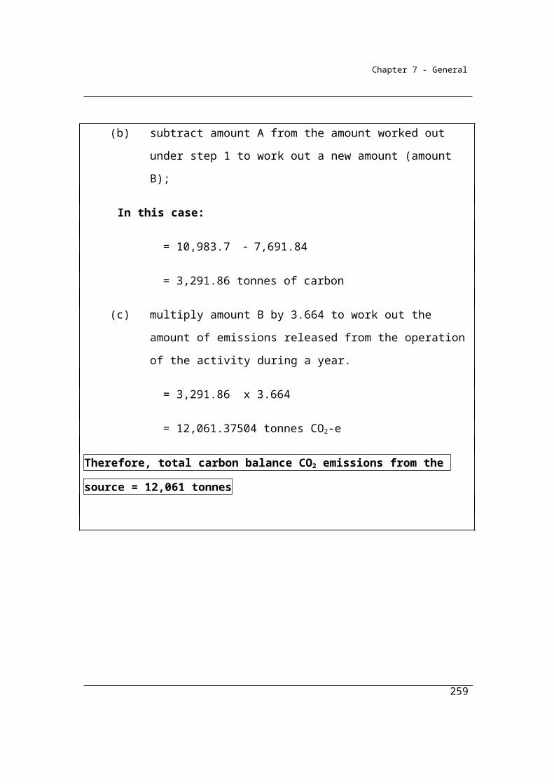
Chapter 7 - General
PRp(bt) is the first 30 days production flow rate in cubic metres per hour for each well (p) and well type (t) measured in a basin (b), estimated in accordance with Division 2.3.6.
(8) For subsection (7), the sampling requirements for the number of well completions or well workovers performed during a year for each basin and well type (horizontal or vertical) are as follows:
(a) if one to 5 well completions or workovers are performed during a year, all wells are to be measured;
(b) if 6 to 50 well completions or workovers are performed during a year, a minimum of 5 wells are to be measured;
(c) if more than 50 well completions or workovers are performed during a year, a minimum of 10% of wells are to be measured.
Example of estimating vented emissions from well completions and well workovers using method 4 - subsection (1) Vented volume measured for all wells and well types in a basin
Where in subsection (1)
Input Data
An example is detailed in the table below of a company performing four well completions during the year in a basin. The company chooses to use the method 4 approach set out in subsection (1) where the vented volume is measured for all four wells. The volume of the flowback gas and gas injected were measured for each well and converted to standard conditions (columns B and C). The methane and carbon dioxide composition of the injected were determined (columns D and E)
259
Chapter 7 - General
A B C D E F G
Well No.
Flow volume of flowback measured for well in standard
conditions
Volume of gas
injected into well,
in standard
conditions
CH4 share of one
mole of VIp, as a
percentage
CO2 share of one
mole of VIp, as a
percentage
Volume of CH4
injected into well
Volume of CO2
injected into well
FVp VIp molp % molp % VIGGp VIGGp
Cubic metres
Cubic metres % % Cubic
metresCubic metres
D x C E x C
1 22 2 20 80 0.4 1.6
2 50 5 25 75 1.25 3.75
3 27 8 90 10 7.2 0.8
Step 1 Calculate VIGGjp - the volume of CH4 and CO2 injected into each well.
VIGGj,p is worked in subsection (3) using the following formula:
VIp × molj,p %
Referring to the table above, VIGGp for methane and carbon dioxide have been worked out for each well in columns F and G respectively.
Step 2 Calculate ESp ; the volume of CH4 vented from strata for each well.
ESp is worked in subsection (2) using the following formula:
FVp - VIp
Referring to the table above, ESp has been worked out for each well in column H.
Step 3 Calculate total vented methane and carbon dioxide volumes for each well:
260
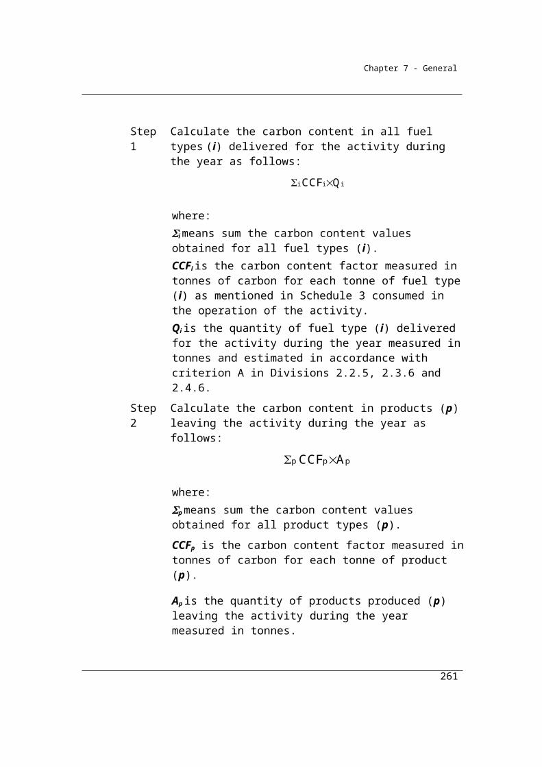
Chapter 7 - General
For methane (column I) = ESp (column H) + VIGGp (column F)
For carbon dioxide (column J) = VIGGp (column G)
A F H I J
Well No.
Volume of CH4
injected into well
Volume of CH4
vented from
strata for each well
CH4 well emissions
CO2 well emissions.
Equals the Volume of
CO2
injected into well
(VIGGp) (ESp) (VIGGp)
Cubic metres
Cubic metres
Cubic metres
Cubic metres
F + H G
1 0.4 20 20.4 1.6
2 1.25 45 46.25 3.75
3 7.2 19 26.2 0.8
4 3.8 11 14.8 0.2
Step 4 Calculate final methane and carbon dioxide emissions for all wells:
Sum emissions for all wells by gas type and convert from cubic metres to tonnes CO2-e.
For methane:
Sum column I
= 20.4 + 46.25 + 26.2 + 14.8
= 107.65 m3
Methane conversion factor γj = 6.784 × 10-4 × 25
261
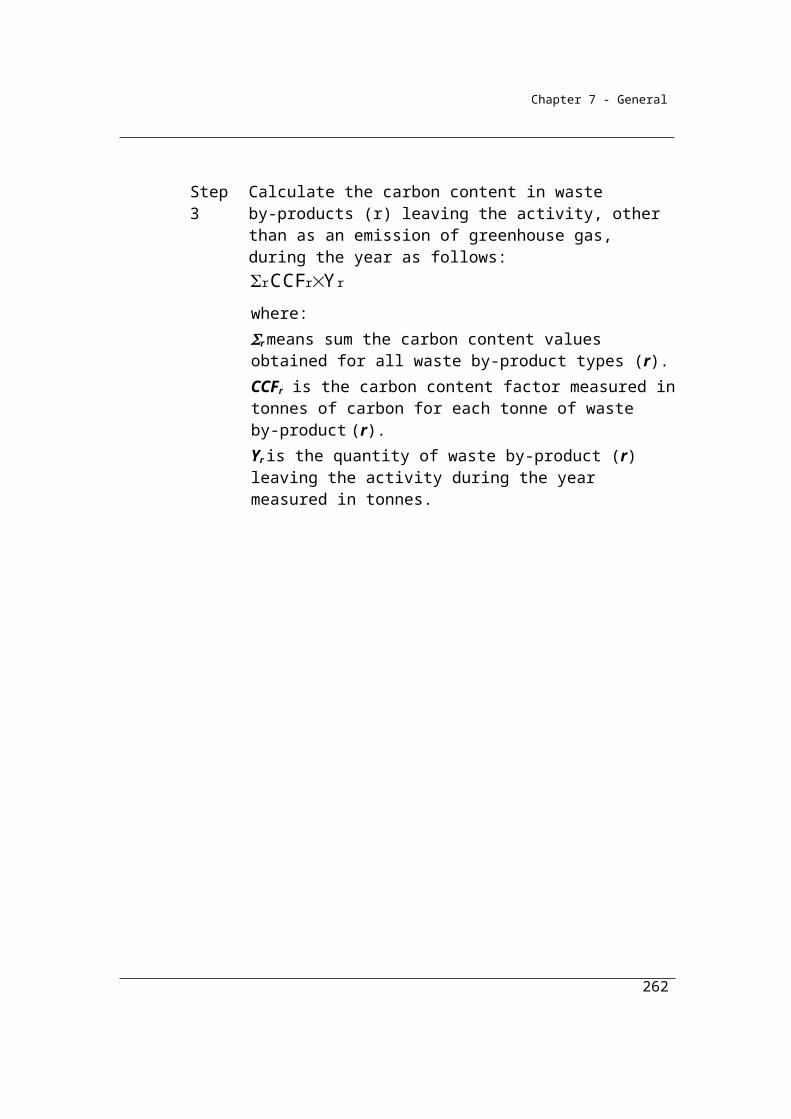
Chapter 7 - General
= 107.65 x 6.784 × 10-4 × 25
= 1.8257 tonnes CO2-e
For carbon dioxide:
Sum column J
= 1.6 + 3.75 + 0.8 + 0.2
= 6.35 m3
Carbon dioxide conversion factor γj = 1.861 × 10-3
= 6.35 x 1.861 × 10-3
= 0.012 tonnes CO2-e
Therefore: total vented emissions from well completions performed to the four wells during the year are:
Methane = 1.8257 tonnes CO2-e
Carbon dioxide = 0.012 tonnes CO2-e
262

Chapter 7 - General
Example of estimating vented emissions from well completions and well workovers using method 4 - subsection (1) Vented volume measured for a sample of wells and well types in a basin
Where in subsection (4)
Input Data
An example is detailed in the table below of a company performing four well completions during the year in a basin. The company chooses to use the method 4 approach set out in subsection (4) where the vented volume is estimated using the measurement of flowback and production rate within a well sampling framework.
The average rate of flowback gas per well completion (FRp(bt) ) and the average 30 day production rate per well (PRp(bt) ) were deterimined by measurement (columns B and C).
The total number of hours of flowback for the well completion (Tp ) were recorded (column D).
The volumes of gas injected were measured for each well (VIp ) and converted to standard conditions (column E). The methane and carbon dioxide composition (molj,p%) of the injected gas were determined (columns F and G). Volumes of methane and carbon dioxide captured during well completions (SGj,p ), converted to standard conditions, were estimated for each well (columns J and K).
263
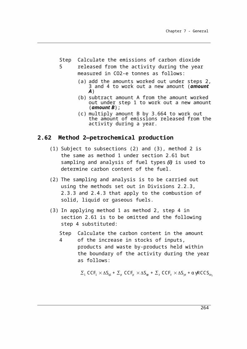
Chapter 7 - General
A B C D E F G H I J
Well No.
Average rate of
flowback gas per
well completio
n
Average 30 day
production rate per
well
Number of hours
of flowback
for the well
completion
Volume of gas
injected into well
CH4 share of one
mole of VIp, as a
percentage
CO2 share of one
mole of VIp, as a percentag
e
Volume of CH4
injected into well
Volume of CO2
injected into well
Volumeof CH4
captured
FRp(bt) PRp(bt) Tp VIp molp % molp % VIGGp VIGGp SGj,p
Cubic metres
per hour
Cubic metres
per hourHours Cubic
metres % % Cubic metres
Cubic metres
Cubicmetres
E x F E x G
1 5 2 22 2 20 80 0.4 1.6 8
2 4 2 50 5 25 75 1.25 3.75 8
3 3 1 27 8 90 10 7.2 0.8 7
4 6 4 87 4 95 5 3.8 0.2 8
Step 1 Determine the well sampling requirements:
Sampling requirments are set out in subsection (8). In this example only four vertical well completions were performed in the basin during the year. Therefore, according to paragraph (8)(a), all four wells are required to be measured.
Step 2 Calculate FRMbt ; the ratio of flowback during well completions to the 30 day production rate for each well.
FRMbt is worked in subsection (7) using the following formula:
264
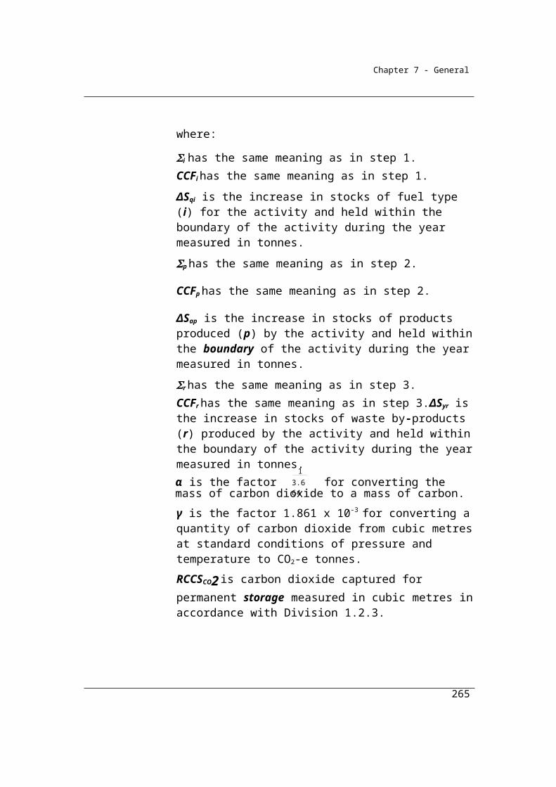
Chapter 7 - General
Therefore FRMbt is calculated for each well in column L of the following table:
A B C L
Well No. Average rate of flowback gas per well completion
Average 30 day production rate per well
The ratio of flowbackduring well completions tothe 30 day production rate
FRp(bt) PRp(bt) FRMbt
Cubic metres per hour Cubic metres per hour
B / C
1 5 2 2.5
2 4 2 2
3 3 1 3
Step 3 Calculate EVp ; the volume of methane flowback during a well completion from strata for each well.
EVp is worked in subsection (5) using the following formula:
Therefore EVp is calculated for each well in column M of the following table:
265
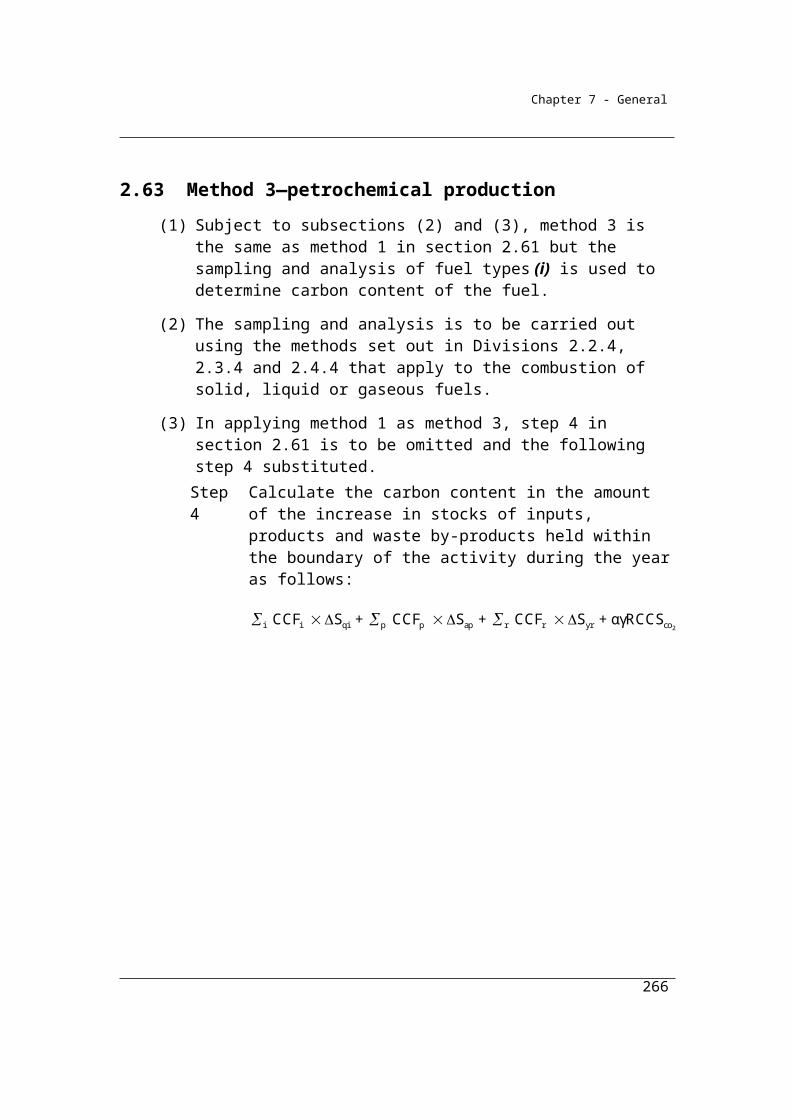
Chapter 7 - General
A D L C E M
Well No.
Number of hours of flowback for
the well completion
The ratio of flowback during well completions
to the 30 day production rate
Average 30 day production rate
per well
Volume of gas injected into
well, in standard conditions
Volume of CHflowback during
a well completion from
strata
Tp FRMbt PRp(bt) VIp EVp
Hours Cubic metres per hour Cubic metres Cubic metres
D x L x C - E
1 22 2.5 2 2 108
2 50 2 2 5 195
3 3 1 8 73
Step 4 Calculate VIGGjp ; the volume of CH4 and CO2 injected into each well.
VIGGj,p is worked in subsection (6) using the following formula:
VIp × molj,p %
Referring to the input data table, VIGG j,p for methane and carbon dioxide have been worked out for each well in columns H and I respectively.
Step 5 Calculate total vented methane and carbon dioxide volumes for each well:
For methane (column N) = EVp (column M) + VIGGp (column H) - SGp (column J)
266

Chapter 7 - General
A M H J
Well No.
Volume of CH4
injected into wellVolume of CH4
injected into wellVolume of CH
captured
EVp VIGGp SG
Cubic metres Cubic metres Cubic metres
1 108 0.4 8
2 195 1.25 8
3 73 7.2 7
4 518 3.8 8
For carbon dioxide (column O) = VIGGp (column I) - SGp (column K)
267

Chapter 7 - General
A I K O
Well No.
Volume of CO2 injected
into well
Volume of CO2
capturedCO2 well emissions
VIGGp SGp
Cubic metres Cubic metres Cubic metres
I - K
1 1.6 0.5 1.1
2 3.75 1 2.75
3 0.8 0 0.8
4 0.2 0 0.2
Step 6 Calculate final methane and carbon dioxide emissions for all wells:
Sum emissions for all wells by gas type and convert from cubic metres to tonnes CO2-e.
For methane
sum column N
= 100.4 + 188.25 + 73.2 + 513.8
= 875.65 m3
Apply methane conversion factor γj = 6.784 × 10-4 × 25
= 875.65 x 6.784 × 10-4 × 25
= 14.851 tonnes CO2-e
268

Chapter 7 - General
For carbon dioxide
Sum column O
= 1.1 + 2.75 + 0.8 + 0.2
= 4.85 m3
Apply carbon dioxide conversion factor γj = 1.861 × 10-3
= 4.85 x 1.861 × 10-3
= 0.009 tonnes CO2-e
Therefore: total vented emissions from well completions performed to the four wells during the year are:
Methane = 14.851 tonnes CO2-e
Carbon dioxide = 0.009 tonnes CO2-e
269
Chapter 7 - General
Division 3.3.3—Crude oil productionEmissions arise for this category from fugitive sources such as leaks, accidental releases, vents, storage losses and from flaring of fuels (that is, the combustion of fuels for non-productive or non-commercial reasons) – for example for health and safety reasons.
Subdivision 3.3.3.1—Preliminary
3.47 Application
(1) This Division applies to fugitive emissions from crude oil production activities, including emissions from flaring, from:
(a) an oil wellhead; and(b) well servicing; and(c) oil sands mining; and(d) shale oil mining; and(e) the transportation of untreated production to treating or extraction
plants; and(f) activities at extraction plants or heavy oil upgrading plants, and gas
reinjection systems and produced water disposal systems associated with the those plants; and
(g) activities at upgrading plants and associated gas reinjection systems and produced water disposal systems.
(2) For paragraph (1)(e), untreated production includes:(a) well effluent; and(b) emulsion; and(c) oil shale; and(d) oil sands.
Subdivision 3.3.3.2—Crude oil production (non-flared)—fugitive leak emissions of methane
Fugitive leakage emissions of methane may occur in crude oil production from sources such as the unintentional equipment leaks from valves, flanges, pump seals, compressor seals, relief valves, sampling connections, process drains, open-ended lines, casing, tanks and other leakage sources from pressurised equipment not classed as a vent.
270

Chapter 7 - General
3.48 Available methods
(1) Subject to section 1.18, for estimating fugitive emissions of methane, other than fugitive emissions of methane specified in subsection (1A), during a year from the operation of a facility that is constituted by crude oil production, one of the following methods must be used:
(a) method 1 under section 3.49;(b) method 2 under section 3.50;
Note: There is no method 3 or 4 for this Division.
(1A) For subsection (1), the following fugitive emissions of methane are specified:
(a) fugitive emissions from oil or gas flaring;(b) fugitive emissions that result from system upsets, accidents or
deliberate releases from process vents.
(2) However, for incidental emissions another method may be used that is consistent with the principles in section 1.13.
Summary of available methods, for estimating fugitive leak emissions from crude oil production (non-flared), by emissions of gas type (j)
CO2 CH4 N2O
Method 1 NO Section 3.49 NO
Method 2 NO Section 3.50 NO
Method 3 NO NA NO
Method 4 NO NA NO
NA = Not available. NO = Not occurring
3.49 Method 1—crude oil production (non-flared) emissions of methane
(1) Method 1 is:
ij k ik ijk i (l) ijE = (Q EF ) + Q EF
where:
Eij is the fugitive emissions of methane (j) from the crude oil production during the year measured in CO2-e tonnes.
271
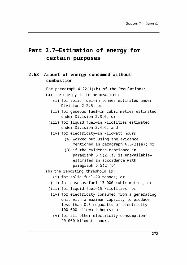
Chapter 7 - General
Σk is the emissions of methane (j) measured in tonnes of CO2-e and estimated by summing up the emissions released from all of the equipment of type (k) specified in column 2 of the table in subsection (2), if the equipment is used in the crude oil production.
Qik is the total of the quantities of crude oil measured in tonnes that pass through each equipment of type (k) specified in column 2 of the table in subsection (2) during the year, if the equipment is used in the crude oil production.
EFijk is the emission factor for methane (j) measured in tonnes of CO2-e per tonne of crude oil that passes through each equipment of type (k) specified in column 2 of the table in subsection (2) during the year, if the equipment is used in the crude oil production.
Qi is the total quantity of crude oil (i) measured in tonnes that passes through the crude oil production.
EF(l) ij is 1.4 x 10⁻³, which is the emission factor for methane (j) from general leaks in the crude oil production, measured in CO2-e tonnes per tonne of crude oil that passes through the crude oil production.
(2) For EFijk mentioned in subsection (1), column 3 of an item in the following table specifies the emission factor for an equipment of type (k) specified in column 2 of that item:
Item Equipment type (k) Emission factor for gas type (j) (tonnes CO2-e/tonnes fuel throughput)CH4
1 Internal floating tank
2 Fixed roof tank
3 Floating tank
(3) For EF(l) ij in subsection (1), general leaks in the crude oil production comprise the emissions (other than vent emissions) from equipment listed in sections 5.4.3, 5.6.4, 5.6.5 and 6.1.2 of the API Compendium, if the equipment is used in the crude oil production.
272

Chapter 7 - General
3.50 Method 2—crude oil production (non-flared) emissions of methane
Method 2 requires the use of equipment-specific emission factors and more detail on the types of equipment used at the facility. The Method is intended to be as specified in the American Petroleum Institute’s Compendium of Greenhouse Gas Emissions Estimation Methodologies for the Oil and Natural Gas Industry 2009, sections 5 and 6.1.2.
(1) Method 2 is:
ij k ik ijkE = (Q EF )
where:
Eij is the fugitive emissions of methane (j) from the crude oil production during the year measured in CO2-e tonnes.
Σk is the emissions of methane (j) measured in tonnes of CO2-e and estimated by summing up the emissions released from each equipment type (k) listed in sections 5.4.1, 5.4.2, 5.4.3, 5.6.4, 5.6.5 and 6.1.2 of the API Compendium, if the equipment type is used in the crude oil production.
Qik is the total of the quantities of crude oil that pass through each equipment type (k), or the number of equipment units of type (k), listed in sections 5.4.1, 5.4.2, 5.4.3, 5.6.4, 5.6.5 and 6.1.2 of the API Compendium, if the equipment is used in the crude oil production, measured in tonnes.
EFijk is the emission factor of methane (j) measured in tonnes of CO2-e per tonne of crude oil that passes through each equipment type (k) listed in sections 5.4.1, 5.4.2, 5.4.3, 5.6.4, 5.6.5 and 6.1.2 of the API Compendium, if the equipment is used in the crude oil production.
(2) For EFijk, the emission factors for methane (j), as crude oil passes through an equipment type (k), are:
(a) as listed in sections 5.4.1, 5.4.2, 5.4.3, 5.6.4, 5.6.5 and 6.1.2 of the API Compendium, for the equipment type; or
(b) if the manufacturer of the equipment supplies equipment-specific emission factors for the equipment type—those factors.
273

Chapter 7 - General
Subdivision 3.3.3.3—Crude oil production (flared)—fugitive emissions of carbon dioxide, methane and nitrous oxide
Methods 1, 2 and 3 are provided for flaring of fuels. Methods 2 and 3 rely on the sampling and analysis of the fuel to estimate the composition of the gases in the fuel
in accordance with the provisions of chapter 2.
3.51 Available methods
(1) Subject to section 1.18, for estimating emissions released by oil or gas flaring during a year from the operation of a facility that is constituted by crude oil production:
(a) if estimating emissions of carbon dioxide released—one of the following methods must be used:(i) method 1 under section 3.52;
(ii) method 2 under section 3.53;(iii) method 3 under section 3.54; and
(b) if estimating emissions of methane released—one of the following methods must be used:(i) method 1 under section 3.52;
(ii) method 2A under section 3.53A; and(c) if estimating emissions of nitrous oxide released—one of the
following methods must be used:(i) method 1 under section 3.52;
(ii) method 2A under section 3.53A.Note: There is no method 4 under paragraph (a) and no method 2, 3 or 4 under
paragraph (b) or (c).
(2) However, for incidental emissions another method may be used that is consistent with the principles in section 1.13.
274
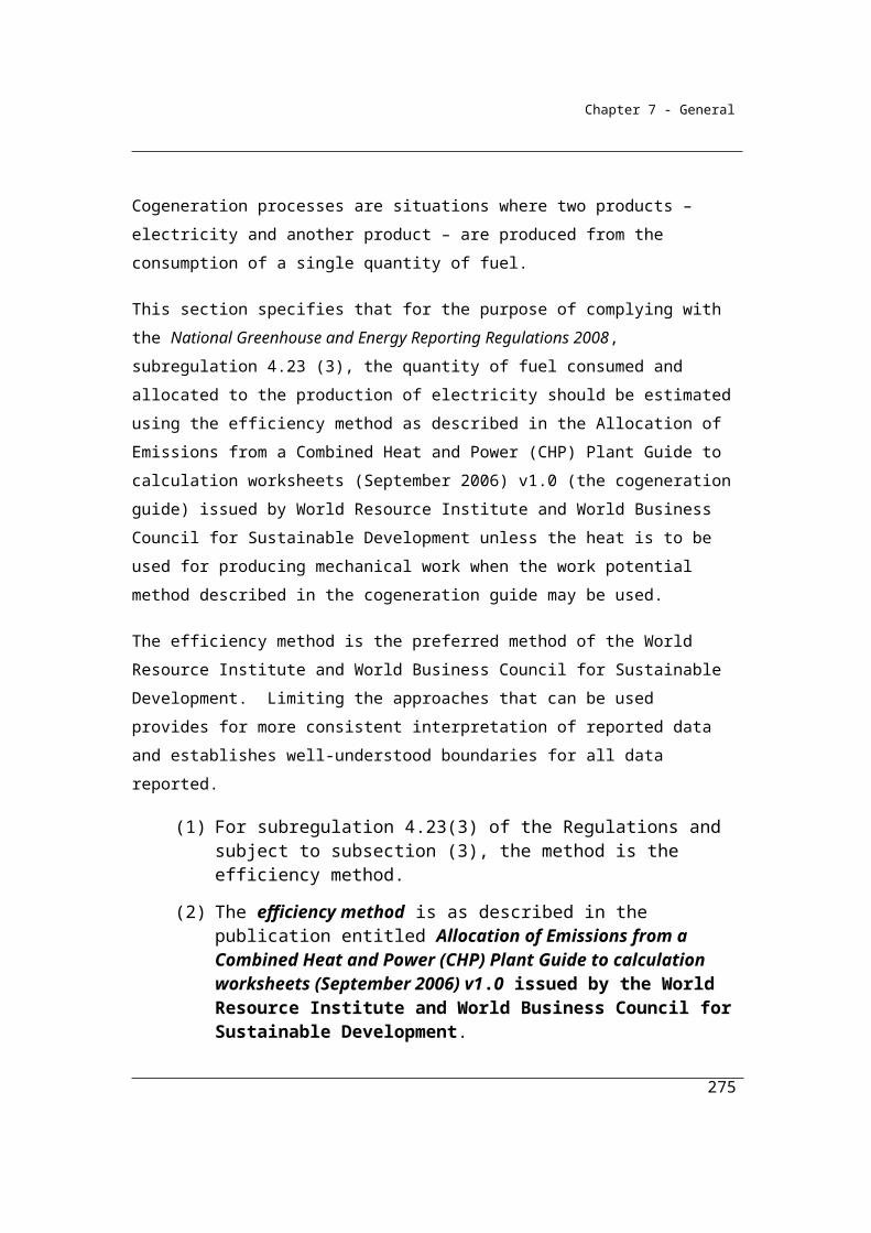
Chapter 7 - General
Available methods, for estimating emissions from crude oil production (flared), by emissions of gas type (j)
CO2 CH4 N2O
Method 1 Section 3.52 Section 3.55 Section 3.55
Method 2 Section 3.53 NA NA
Method 3 Section 3.54 NA NA
Method 4 NA NA NA
NA = Not available. NO = Not occurring
3.52 Method 1—crude oil production (flared) emissions
(1) For subparagraph 3.51(a)(i), method 1 is:
ij i ijE = Q EFwhere:
Eij is the emissions of gas type (j) measured in CO2-e tonnes from a fuel type (i) flared in crude oil production during the year.
Qi is the quantity of fuel type (i) measured in tonnes flared in crude oil production during the year.
EFij is the emission factor for gas type (j) measured in tonnes of CO2-e emissions per tonne of the fuel type (i) flared.
(2) For EFij mentioned in subsection (1), columns 3, 4 and 5 of an item in following table specify the emission factor for each fuel type (i) specified in column 2 of that item.
Item Fuel type (i) Emission factor for gas type (j) (tonnes CO2-e/tonnes of fuel flared)CO2 CH4 N2O
1 Unprocessed gas flared 2.8 0.8 0.032 Crude oil 3.2 0.008 0.07
275
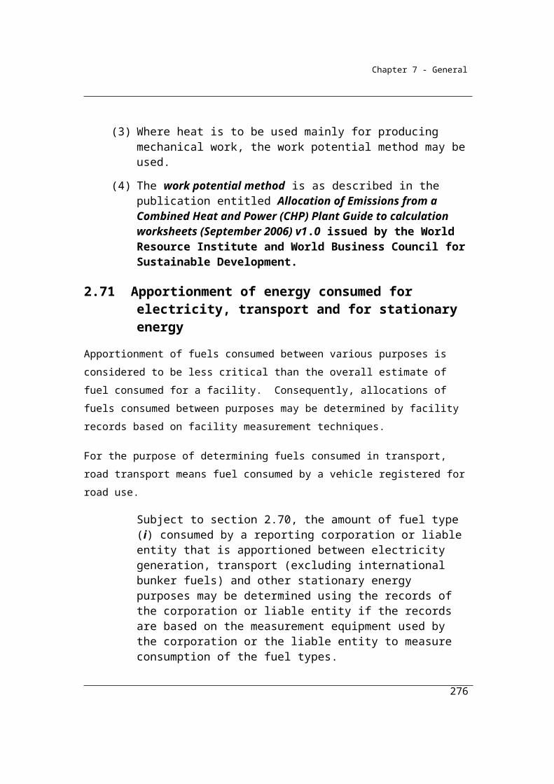
Chapter 7 - General
3.53 Method 2—crude oil production
Combustion of gaseous fuels (flared) emissions of carbon dioxide
(1) For subparagraph 3.51(1)(a)(ii), method 2 for combustion of gaseous fuels is:
2ico 2h h iE = + QCO Q × EF × OF
where:
EiCO2 is the fugitive emissions of CO2 from fuel type (i) flared in crude oil production during the year, measured in CO2-e tonnes.
Qh is the total quantity of hydrocarbons (h) within the fuel type (i) in crude oil production during the year, measured in tonnes in accordance with Division 2.3.3.
EFh is the emission factor for the total hydrocarbons (h) within the fuel type (i) in crude oil production during the year, measured in CO2-e tonnes per tonne of fuel type (i) flared, estimated in accordance with method 2 in Division 2.3.3.
OFi is 0.98, which is the destruction efficiency of fuel type (i) flared.
QCO2 is the quantity of CO2 within the fuel type (i) in crude oil production during the year, measured in CO2-e tonnes in accordance with Division 2.3.3.
Combustion of liquid fuels (flared) emissions of carbon dioxide
(2) For subparagraph 3.51(1)(a)(ii), method 2 for combustion of liquid fuels is the same as method 1, but the carbon dioxide emissions factor EFh must be determined in accordance with method 2 in Division 2.4.3.
3.53A Method 2A—crude oil production (flared methane or nitrous oxide emissions)
For subparagraphs 3.51(1)(b)(ii) and (c)(ii), method 2A is:
where:
EFhij is the emission factor of gas type (j), being methane or nitrous oxide, for the total hydrocarbons (h) within the fuel type (i) in crude oil production during the year, mentioned for the fuel type in the table in
276

Chapter 7 - General
subsection 3.52(2) and measured in CO2-e tonnes per tonne of the fuel type (i) flared.
Eij is the fugitive emissions of gas type (j), being methane or nitrous oxide, from fuel type (i) flared from crude oil production during the year, measured in CO2-e tonnes.
OFi is 0.98, which is the destruction efficiency of fuel type (i) flared.
Qh is the total quantity of hydrocarbons (h) within the fuel type (i) in crude oil production during the year, measured in tonnes in accordance with Division 2.3.3 for gaseous fuels or Division 2.4.3 for liquid fuels.
3.54 Method 3—crude oil production
Combustion of gaseous fuels (flared) emissions of carbon dioxide
(1) For subparagraph 3.51(1)(a)(iii), method 3 for the combustion of gaseous fuels is the same as method 2, but the carbon dioxide emissions factor EFh must be determined in accordance with method 3 in Division 2.3.4.
Combustion of liquid fuels (flared) emissions of carbon dioxide
(2) For subparagraph 3.51(1)(a)(iii), method 3 for the combustion of liquid fuels is the same as method 2, but the carbon dioxide emissions factor EFh must be determined in accordance with method 3 in Division 2.4.4.
Subdivision 3.3.3.4—Crude oil production (non-flared)—fugitive vent emissions of methane and carbon dioxide
3.56A Available methods
(1) Subject to section 1.18, the methods mentioned in subsections (2) and (3) must be used for estimating fugitive emissions that result from system upsets, accidents and deliberate releases from process vents during a year from the operation of a facility that is constituted by crude oil production.
(2) To estimate emissions that result from deliberate releases from process vents, system upsets and accidents during a year from the operation of the facility, one of the following methods must be used:
(a) method 1 under section 3.84;(b) method 4 under Part 1.3.
(3) For estimating incidental emissions that result from deliberate releases from process vents, system upsets and accidents during a year from the
277
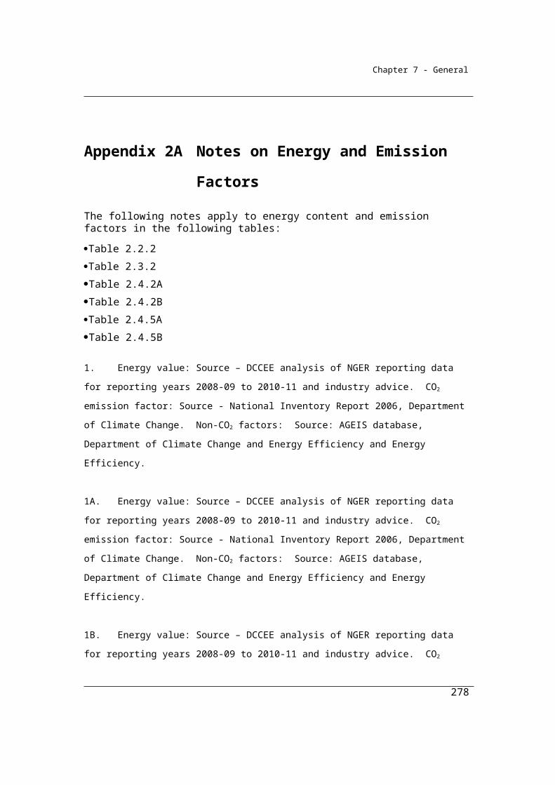
Chapter 7 - General
operation of the facility, another method may be used that is consistent with the principles mentioned in section 1.13.Note: There is no method 2 or 3 for this Subdivision.
Summary of available methods, for estimating fugitive vent emissions from crude oil production (non-flared), by emissions of gas type (j)
CO2 CH4 N2O
Method 1 Section 3.56A Section 3.56A NO
Method 2 NA NA NO
Method 3 NA NA NO
Method 4 Part 1.3 Part 1.3 NO
NA = Not available. NO = Not occurring
Example
A crude oil production platform has a throughput of 710,400 tonnes of crude oil during the year. It has an equipment type constituting a floating tank in which 685,000 tonnes of crude oil throughput occurred during the year. 400 tonnes of crude oil were flared during the year.
The Reporter elects to use Method 1 to calculate fugitive emissions from crude oil production and flaring, for each of the greenhouse emission gases (j) (carbon dioxide, methane and nitrous oxide). Emissions are estimated as follows:
Part A: Crude oil production (non flared component)
where:
Eij is the emissions measured in CO2 e tonnes of methane (j), released from the crude oil production during the year.
Σk is the sum of emissions of methane (j) (tonnes of CO2-e) arising from equipment of types (k) listed in the table in section 3.49.
278
Eij = Σk (Qik EFijk) + Qi EF(l) ij
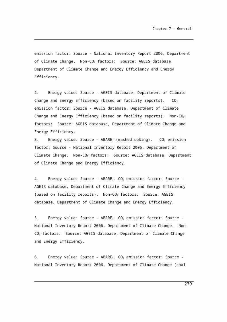
Chapter 7 - General
Qik is the total of the quantities of crude oil (tonnes) that pass through each equipment of type (k) listed in the table in section 3.49 . In this case it is the crude oil throughput for the floating tank is 685,000 tonnes.
EFijk is the emission factor for methane (j) measured as tonnes of CO2-e per tonne of crude oil that passes through each equipment of type (k). In this case the emission factor for the floating tank is 3.2 x 10⁻⁶ CO2-e/tonnes fuel throughput.
Qi is the total quantity of crude oil (i) measured in tonnes of crude oil production. In this case the crude oil production throughput is 710,400 tonnes.
EF(l) ij 1.4 x 10⁻³, is the emission factor for methane (j) from general leaks in the crude oil production, measured in CO2 e tonnes per tonne of crude oil production.
Therefore, the estimate of methane emissions in CO2-e tonnes :
= (685,000 x 4.0 x10-6) + (710,400 x 1.4 x 10-3)
Total emissions of methane = 997 t CO2-e
Part B: Crude oil production (flared component)
where:
Eij is the emissions of gas type (j) (CO2-e tonnes) released from a fuel type (i) flared.
Qi is the quantity of fuel type flared (i) (tonnes). In this case the quantity of crude oil flared is 400 tonnes.
EFij is the emission factor for gas type (j) in tonnes of CO2-e emissions per tonne of the fuel type (i) flared. The emission factors are obtained from Method 1, section 3.52
Therefore, the estimate of greenhouse gas emissions (from carbon dioxide, methane and nitrous oxide (j)) in CO2-e tonnes:
For carbon dioxide
=400 x 3.2
Total emissions of carbon dioxide = 1280 t CO2-e
For methane
=400 x 0.008
279
Eij = Qi EFij
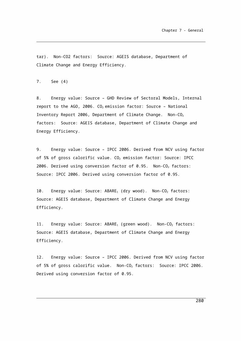
Chapter 7 - General
Total emissions of methane = 3 t CO2-e
For nitrous oxide
=400 x 0.07
Total emissions of nitrous oxide = 28 t CO2-e
Part C: Crude oil production (vented emissions component)
The Reporter is directed to section 3.84 which specifies the applicable sections of the American Petroleum Institute’s Compendium of Greenhouse Gas Emissions Estimation Methodologies for the Oil and Natural Gas Industry 2009(API Compendium). The reporter estimates their vented emissions in accordance with those methods detailed in the API Compendium, producing the following results:
Total emissions of carbon dioxide = 380 t CO2-e
Total emissions of methane = 980 t CO2-e
Division 3.3.4—Crude oil transportThe crude oil transport subsector includes fugitive methane emissions associated with the marine, road and rail transport of crude oil. Emissions result largely from
three types of activities: loading, transit, and ballasting.
3.57 Application
This Division applies to fugitive emissions from crude oil transport activities, other than emissions that are flared.
3.58 Available methods
(1) Subject to section 1.18, one of the following methods must be used for estimating fugitive emissions of methane released during a year from the operation of a facility that is constituted by crude oil transport:
(a) method 1 under section 3.59;(b) method 2 under section 3.60.
Note: There is no method 3 or 4 for this Division.
(2) However, for incidental emissions another method may be used that is consistent with the principles in section 1.13.
280
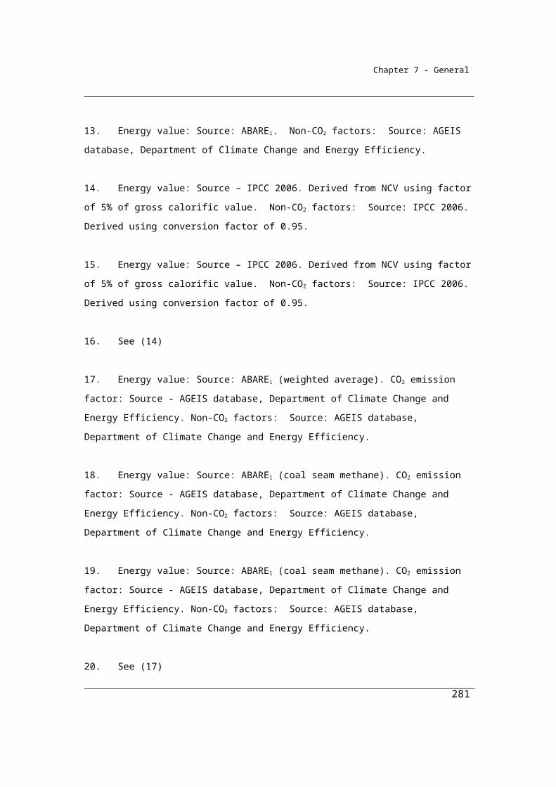
Chapter 7 - General
Available methods, for estimating emissions from crude oil transport), by emissions of gas type (j)
CO2 CH4 N2O
Method 1 NO Section 3.59 NO
Method 2 NO Section 3.60 NO
Method 3 NO NA NO
Method 4 NO NA NO
NA = Not available. NO = Not occurring
3.59 Method 1—crude oil transport
Method 1 for crude oil transport for fugitive emissions is derived from the National Greenhouse Accounts.
Method 1 is:
ij i ijE = Q EF
where:
Eij is the fugitive emissions of methane (j) from the crude oil transport during the year measured in CO2-e tonnes.
Qi is the quantity of crude oil (i) measured in tonnes and transported during the year.
EFij is the emission factor for methane (j), which is 8.7 x 10⁻⁴ tonnes CO2-e per tonnes of crude oil transported during the year.
3.60 Method 2—fugitive emissions from crude oil transport
Method 2 requires the use of equipment-specific emission factors and more detail on the types of equipment used at the facility. The Method is intended to be as specified in the American Petroleum Institute’s Compendium of Greenhouse Gas Emissions Estimation Methodologies for the Oil and Natural Gas Industry 2009sections 5 and 6.1.2.
281
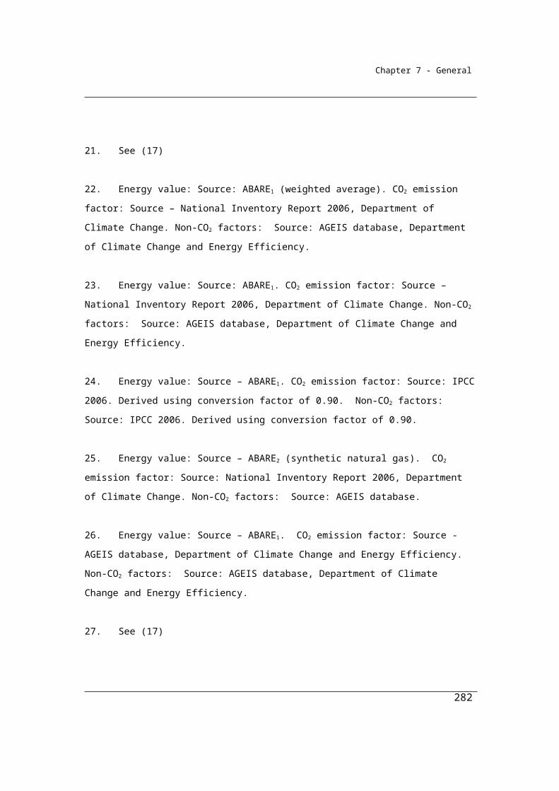
Chapter 7 - General
(1) Method 2 is:
ij k ik ijkE = (Q EF )
where:
Eij is the fugitive emissions of methane (j) from the crude oil transport during the year measured in CO2-e tonnes.
Σk is the emissions of methane (j) measured in tonnes of CO2-e and estimated by summing up the emissions from each equipment type (k) listed in sections 5 and 6.1.2 of the API Compendium, if the equipment is used in the crude oil transport.
Qik is the total of the quantities of crude oil measured in tonnes that pass through each equipment type (k) listed in sections 5 and 6.1.2 of the API Compendium, if the equipment is used in the crude oil transport.
EFijk is the emission factor of methane (j) measured in tonnes of CO2-e per tonne of crude oil that passes though each equipment type (k) listed in sections 5 and 6.1.2 of the API Compendium, if the equipment is used in the crude oil transport.
(2) For EFijk, the emission factors for methane (j), as crude oil passes through equipment type (k), are:
(a) as listed in sections 5 and 6.1.2 of the API Compendium, for the equipment type; or
(b) if the manufacturer of the equipment supplies equipment-specific emission factors for the equipment type—those factors.
282
Chapter 7 - General
Division 3.3.5—Crude oil refiningEmissions arise for this category from fugitive sources (for example gas leaks), flaring and from the process vents, system upsets and accidents, including the combustion of catalyst coke for non-energy purposes.
Other sources of emissions arising from the crude oil refining, such as from the combustion of fuels for energy or from the production of hydrogen, are not described in this chapter and must be estimated using the Methods described in other chapters.
3.61 Application
This Division applies to fugitive emissions from crude oil refining activities, including emissions from flaring at petroleum refineries.
3.62 Available methods
(1) Subject to section 1.18, for estimating emissions released during a year from the operation of a facility that is constituted by crude oil refining the methods as set out in this section must be used.
Crude oil refining and storage tanks
(2) One of the following methods must be used for estimating fugitive emissions of methane that result from crude oil refining and from storage tanks for crude oil:
(a) method 1 under section 3.63;(b) method 2 under section 3.64.
Note: There is no method 3 or 4 for subsection (2).
Process vents, system upsets and accidents
(3) One of the following methods must be used for estimating fugitive emissions of each type of gas, being carbon dioxide, methane and nitrous oxide, that result from deliberate releases from process vents, system upsets and accidents:
(a) method 1 under section 3.65;(b) method 4 under section 3.66.
Note: There is no method 2 or 3 for subsection (3).
283
Chapter 7 - General
Flaring
(4) For estimating emissions released from gas flared from crude oil refining:(a) one of the following methods must be used for estimating emissions
of carbon dioxide released:(i) method 1 under section 3.67;
(ii) method 2 under section 3.68;(iii) method 3 under section 3.69; and
(b) if estimating emissions of methane released—one of the following methods must be used:(i) method 1 under section 3.67;
(ii) method 2A under section 3.68A; and(c) if estimating emissions of nitrous oxide released—one of the
following methods must be used:(i) method 1 under section 3.67;
(ii) method 2A under section 3.68A.Note: The flaring of gas from crude oil refining releases emissions of carbon
dioxide, methane and nitrous oxide. The reference to gas type (j) in method 1 under section 3.67 is a reference to these gases. The same formula is used to estimate emissions of each of these gases. There is no method 4 for emissions of carbon dioxide and no method 2, 3 or 4 for emissions of nitrous oxide or methane.
(5) However, for incidental emissions another method may be used that is consistent with the principles in section 1.13.
Summary of available methods, for estimating emissions from crude oil refining, by emissions of gas type (j)
284

Chapter 7 - General
NA = Not available. NO = Not occurring
Subdivision 3.3.5.1—Fugitive emissions from crude oil refining and from storage tanks for crude oil
3.63 Method 1—crude oil refining and storage tanks for crude oil
Method 1 for fugitive emissions from crude oil refining is derived from the National Greenhouse Accounts.
Method 1 is:
285
CO2 CH4 N2O
Crude oil refining and storage tanks
Method 1 NO Section 3.63 NO
Method 2 NO Section 3.64 NO
Methods 3, 4 NO NA NO
Process vents, system upsets and accidents
Method 1 Section 3.65 Section 3.65 Section 3.65
Methods 2, 3 NA NA NA
Method 4 Section 3.66 Section 3.66 Section 3.66
Flaring
Method 1 Section 3.67 Section 3.67 Section 3.67
Method 2 Section 3.68 NA NA
Method 3 Section 3.69 NA NA
Method 4 NA NA NA
Chapter 7 - General
ij i i ijE = Q EF where:
Eij is the fugitive emissions of methane (j) from fuel type (i) being crude oil refined or stored in tanks during the year measured in CO2-e tonnes.
∑I is the sum of emissions of methane (j) released during refining and from storage tanks during the year.
Qi is the quantity of crude oil (i) refined or stored in tanks during the year measured in tonnes.
EFij is the emission factor for methane (j) being 8.5 x 10⁻⁴ tonnes CO2-e per tonne of crude oil refined and 1.5 x 10⁻⁴ tonnes CO2-e per tonne of crude oil stored in tanks.
3.64 Method 2—crude oil refining and storage tanks for crude oil
Method 2 for fugitive emissions from crude oil refining requires the use of equipment-specific emission factors and more detail on the types of equipment used at the facility. The Method is intended to be as specified in the American Petroleum Institute’s Compendium of Greenhouse Gas Emissions Estimation Methodologies for the Oil and Natural Gas Industry 2009 sections 5 and 6.1.2.
(1) Method 2 is:
ij k ik ijkE = (Q EF )
where:
Eij is the fugitive emissions of methane (j) from the crude oil refining and from storage tanks during the year measured in CO2-e tonnes.
Σk is the emissions of methane (j) measured in tonnes of CO2-e estimated by summing up the emissions released from each equipment types (k) listed in sections 5 and 6.1.2 of the API Compendium, if the equipment is used in the crude oil refining and in the storage tanks.
Qik is the total of the quantities of crude oil measured in tonnes that pass through each equipment type (k) listed in sections 5 and 6.1.2 of the API Compendium, if the equipment is used in the crude oil refining and in the storage tanks.
EFijk is the emission factor for methane (j) measured in tonnes of CO2-e per tonne of crude oil that passes though each equipment type (k) listed in
286
Chapter 7 - General
sections 5 and 6.1.2 of the API Compendium, if the equipment is used in the crude oil refining and in the storage tanks.
(2) For EFijk, the emission factors for methane (j) as the crude oil passes through an equipment type (k) are:
(a) as listed in sections 5 and 6.1.2 of the API Compendium, for the equipment type; or
(b) if the manufacturer of the equipment supplies equipment-specific emission factors for the equipment type—those factors.
Subdivision 3.3.5.2—Fugitive emissions from deliberate releases from process vents, system upsets and accidents
3.65 Method 1—fugitive emissions from deliberate releases from process vents, system upsets and accidents
Method 1 for the estimation of emissions from the burning of catalyst coke for non-energy purposes is derived from the American Petroleum Institute’s Compendium of Greenhouse Gas Emissions Estimation Methodologies for the Oil and Natural Gas Industry 2009 sections 5.2.
It is intended that there should be no double count or omissions of emissions from the estimation of emissions from the combustion of the catalyst coke. Where it is difficult to distinguish between the emissions from combustion of catalyst coke for non-energy purposes from its use as an energy source, it is intended that all emissions should be attributed to the combustion of fuels for energy.
Method 1 is:
i i iE = Q CCF
where:
Ei is the fugitive emissions of carbon dioxide during the year from deliberate releases from process vents, system upsets and accidents in the crude oil refining measured in CO2-e tonnes.
Qi is the quantity of refinery coke (i) burnt to restore the activity of the catalyst of the crude oil refinery (and not used for energy) during the year measured in tonnes.
CCFi is the carbon content factor for refinery coke (i) as mentioned in Schedule 3.
287

Chapter 7 - General
3.664 is the conversion factor to convert an amount of carbon in tonnes to an amount of carbon dioxide in tonnes.
3.66 Method 4—deliberate releases from process vents, system upsets and accidents
Method 4 is provided as an additional option and is taken from the American Petroleum Institute’s Compendium of Greenhouse Gas Emissions Estimation Methodologies for the Oil and Natural Gas Industry 2009 sections 5 and 6.1.2. Consistent with the American Petroleum Institute methodology, emissions of carbon monoxide must be treated as if they fully oxidise to carbon dioxide and estimated
accordingly.
(1) Method 4 is:(a) is as set out in Part 1.3; or(b) uses the process calculation approach in section 5.2 of the API
Compendium.
(2) For paragraph (1)(b), all carbon monoxide is taken to fully oxidise to carbon dioxide and must be included in the calculation.
Subdivision 3.3.5.3—Fugitive emissions released from gas flared from the oil refinery
Flares are commonly used at refineries for the disposal of vented waste gases. The flaring of refinery gases results in the emission of CO2, methane, nitrous oxide and products of incomplete combustion. Method 1 is derived from the methods used for the National Greenhouse Accounts. Methods 2 and 3 rely on the sampling and analysis of the fuel to estimate the composition of the gases in the fuel in accordance with the provisions of chapter 2.
3.67 Method 1—gas flared from crude oil refining
(1) Method 1 is:
ij i ijE = Q EF
where:
Eij is the emissions of gas type (j) released from the gas flared in the crude oil refining during the year measured in CO2-e tonnes.
288
Chapter 7 - General
Qi is the quantity of gas type (i) flared during the year measured in tonnes.
EFij is the emission factor for gas type (j) measured in tonnes of CO2-e emissions per tonne of gas type (i) flared in the crude oil refining during the year.
(2) For EFij in subsection (1), columns 3, 4 and 5 of an item in the following table specify the emission factor for gas type (j) for the fuel type (i) specified in column 2 of that item:
Item fuel type (i) Emission factor of gas type (j) (tonnes CO2-e/tonnes fuel flared)CO2 CH4 N2O
1 gas 2.7 0.1 0.03
3.68 Method 2—gas flared from crude oil refining
For subparagraph 3.62(4)(a)(ii), method 2 is:
2ico h h i 2E = + QCO Q × EF × OF
where:
EiCO2 is the fugitive emissions of CO2 from fuel type (i) flared in crude oil refining during the year, measured in CO2-e tonnes.
Qh is the total quantity of hydrocarbons (h) within the fuel type (i) in crude oil refining during the year, measured in tonnes in accordance with Division 2.3.3.
EFh is the emission factor for the total hydrocarbons (h) within the fuel type (i) in the crude oil refining during the year, measured in CO2-e tonnes per tonne of fuel type (i) flared, estimated in accordance with method 2 in Division 2.3.3.
OFi is 0.98, which is the destruction efficiency of fuel type (i) flared.
QCO2 is the quantity of CO2 within the fuel type (i) in the crude oil refining during the year, measured in CO2-e tonnes in accordance with Division 2.3.3.
3.68A Method 2A—crude oil refining (flared methane or nitrous oxide emissions)
For subparagraphs 3.62(4)(b)(ii) and (c)(ii), method 2A is:
289

Chapter 7 - General
where:
EFhij is the emission factor of gas type (j), being methane or nitrous oxide, for the total hydrocarbons (h) within the fuel type (i) in crude oil refining during the year, mentioned for the fuel type in the table in subsection 3.67(2) and measured in CO2-e tonnes per tonne of the fuel type (i) flared.
Eij is the fugitive emissions of gas type (j), being methane or nitrous oxide, from fuel type (i) flared from crude oil refining during the year, measured in CO2-e tonnes.
OFi is 0.98, which is the destruction efficiency of fuel type (i) flared.
Qh is the total quantity of hydrocarbons (h) within the fuel type (i) in crude oil refining during the year, measured in tonnes in accordance with Division 2.3.3.
3.69 Method 3—gas flared from crude oil refining
For subparagraph 3.62(4)(a)(iii), method 3 is the same as method 2 under section 3.68, but the emission factor EFij must be determined in accordance with method 3 for the consumption of gaseous fuels as specified in Division 2.3.4.
Estimating carbon dioxide emissions from crude oil refining flaring using
Method 2
Crude oil refining usually involves some flaring of a waste gas stream. In this
example a facility flares a waste gas stream of 10,000 tonnes during the year, which
contains a relatively high content of carbon dioxide in addition to some hydrogen
sulphide and hydrocarbons. The reporters have chosen to use method 2 as this
approach provides the opportunity to develop a carbon dioxide emission factor that
better reflects the hydrocarbons present in the gas stream, as well as account for the
in-situ carbon dioxide quantity which is emitted, but not combusted in the flare.
290

Chapter 7 - General
Calculate the carbon dioxide emissions using Method 2 in section 3.68 of NGER
(Measurement) Determination
Eico2 = (Qh × EFh × OFi ) + QCO2
Where:
EiCO2 is the fugitive emissions of CO2 from fuel type (i) flared in crude oil refining during
the year, measured in CO2-e tonnes.
Qh is the total quantity of hydrocarbons (h) within the fuel type (i) in crude oil refining
during the year, measured in tonnes in accordance with Division 2.3.3.
QCO2 is the quantity of CO2 within the fuel type (i) in crude oil refining during the year,
measured in CO2-e tonnes in accordance with Division 2.3.3.
In this example it was determined (in accordance with Division 2.3.3) that the average
composition of the waste gas stream being flared during the year is as follows:
Hydrocarbons C1 to C5 = 0.87 tonnes/ tonne of waste gas stream
Hydrogen sulphide = 0.05 tonnes/ tonne of waste gas stream
Nitrogen = 0.02 tonnes/ tonne of waste gas stream
Carbon dioxide = 0.06 tonnes/ tonne of waste gas stream
Therefore:
Qh = 0.87 x 10,000 t of waste gas stream flared during the year
Qh = 8700 tonnes
291

Chapter 7 - General
QCO2 = 0.06 x 10,000 t of waste gas stream flared during the year
QCO2 = 600 tonnes
EFh is the emission factor for the total hydrocarbons (h) within the fuel type (i) in crude
oil refining during the year, measured in CO2-e tonnes per tonne of fuel type (i) flared,
estimated in accordance with method 2 in Division 2.3.3.
In this example it was determined (in accordance with Division 2.3.3) that the emission
factor derived from the average hydrocarbon composition of the waste gas stream
being flared during the year was:
2.4 tonnes of CO2 per tonne of waste gas stream flared
Therefore:
EFh = 2.4
OFi is 0.98, which is the correction factor for the oxidation of fuel type (i) flared.
To calculate the CO2 emissions from waste gas flared:
= (8700 x 2.4 x 0.98) + 600 = 21,062.4
Therefore, the total emissions from the source = 21,062 tonnes of CO2
292
Chapter 7 - General
Division 3.3.6—Natural gas production or processing, other than emissions that are vented or flared
Fugitive leakage emissions of methane may occur in natural gas production from sources such as the unintentional equipment leaks from valves, flanges, pump seals, compressor seals, relief valves, sampling connections, process drains, open-ended lines, casing, tanks and other leakage sources from pressurised equipment not classed as a vent.
The venting of CO2 and methane extracted from raw gas and flaring of unusable gas produced at various stages of processing are separately accounted for under venting and flaring.
Other sources of emissions arising from natural gas production and processing, such as from the combustion of fuels for energy, are not described in this chapter and must be estimated using the Methods described in other chapters.
Note that in this part the definition of natural gas is as follows:
natural gas includes coal seam methane that is captured for combustion where the production of coal is not intended to occur
3.70 Application
This Division applies to fugitive emissions from natural gas production or processing activities, other than emissions that are vented or flared, including emissions from:
(a) a gas wellhead through to the inlet of gas processing plants; and(b) a gas wellhead through to the tie-in points on gas transmission
systems, if processing of natural gas is not required; and(c) gas processing plants; and(d) well servicing; and(e) gas gathering; and(f) gas processing and associated waste water disposal and acid gas
disposal activities.
293
Chapter 7 - General
3.71 Available methods
(1) Subject to section 1.18, one of the following methods must be used for estimating fugitive emissions of methane (other than emissions that are vented or flared) released during a year from the operation of a facility that is constituted by natural gas production and processing:
(a) method 1 under section 3.72;(b) method 2 under section 3.73.
Note: There is no method 3 or 4 for this Division.
(2) However, for incidental emissions another method may be used that is consistent with the principles in section 1.13.
Summary of available methods, for estimating emissions from natural gas production and processing (other than emissions that are vented or flared), by emissions of gas type (j)
CO2 CH4 N2O
Method 1 NO Section 3.72 NO
Method 2 NO Section 3.73 NO
Method 3 NO NA NO
Method 4 NO NA NO
NA = Not available. NO = Not occurring
3.72 Method 1—natural gas production and processing (other than emissions that are vented or flared)
(1) Method 1 is:
ij k ik ijk i (l) ijE = (Q EF ) + Q EF
where:
Eij is the fugitive emissions of methane (j) (other than emissions that are vented or flared) from the natural gas production and processing during the year measured in CO2-e tonnes.
Σk is the total emissions of methane (j), measured in CO2-e tonnes and estimated by summing up the emissions released from each equipment
294
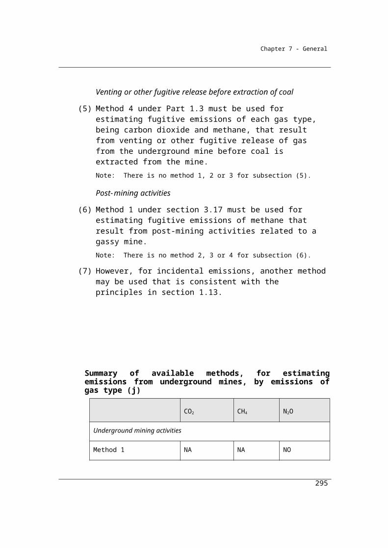
Chapter 7 - General
type (k) specified in column 2 of an item in the table in subsection (2), if the equipment is used in the natural gas production and processing.
Qik is the total of the quantities of natural gas that pass through each equipment type (k), or the number of equipment units of type (k) specified in column 2 of the table in subsection (2), measured in tonnes.
EFijk is the emission factor for methane (j) measured in CO2-e tonnes per tonne of natural gas that passes through each equipment type (k) during the year if the equipment is used in the natural gas production and processing.
Qi is the total quantity of natural gas (i) that passes through the natural gas production and processing measured in tonnes.
EF(l) ij is 1.2 x 10⁻³, which is the emission factor for methane (j) from general leaks in the natural gas production and processing, measured in CO2-e tonnes per tonne of natural gas that passes through the natural gas production and processing.
(2) For EFijk in subsection (1), column 3 of an item in the following table specifies the emission factor for methane (j) for an equipment type (k) specified in column 2 of that item:
Item Equipment type (k) Emission factor for methane (j) (tonnes CO2-e/tonnes fuel throughput)
1 Internal floating tank
2 Fixed roof tank
3 Floating tank
(3) For EF(l) ij in subsection (1), general leaks in the natural gas production and processing comprise the emissions (other than vent emissions) from equipment listed in sections 5.4.3, 5.6.4, 5.6.5 and 6.1.2 of the API Compendium, if the equipment is used in the natural gas production and processing.
3.73 Method 2—natural gas production and processing (other than venting and flaring)
Method 2 for fugitive emissions from natural gas production and processing requires the use of equipment-specific emission factors and more detail on the types of equipment used at the facility. The Method is intended to be as specified in the American Petroleum Institute’s Compendium of Greenhouse Gas Emissions
295

Chapter 7 - General
Estimation Methodologies for the Oil and Natural Gas Industry 2009 sections 5 and 6.1.2.
(1) Method 2 is:
ij k ik ijkE = (Q EF )
where:
Eij is the fugitive emissions of methane (j) from the natural gas production and processing during the year measured in CO2-e tonnes.
Σk is the emissions of methane (j) measured in CO2-e tonnes and estimated by summing up the emissions released from each equipment type (k) listed in sections 5.4.1, 5.4.2, 5.4.3, 5.6.4, 5.6.5 and 6.1.2 of the API Compendium, if the equipment is used in the natural gas production and processing.
Qik is the total of the quantities of natural gas measured in tonnes that pass through each equipment type (k) listed in sections 5.4.1, 5.4.2, 5.4.3, 5.6.4, 5.6.5 and 6.1.2 of the API Compendium, if the equipment is used in the natural gas production and processing.
EFijk is the emission factor of methane (j) measured in tonnes of CO2-e per tonne of natural gas that passes through each equipment type (k) listed in sections 5.4.1, 5.4.2, 5.4.3, 5.6.4, 5.6.5 and 6.1.2 of the API Compendium, if the equipment is used in the natural gas production and processing.
(2) For EFijk, the emission factors for methane (j) as the natural gas passes through the equipment types (k) are:
(a) as listed in sections 5.4.1, 5.4.2, 5.4.3, 5.6.4, 5.6.5 and 6.1.2 of the API Compendium, for the equipment type; or
(b) if the manufacturer of the equipment supplies equipment-specific emission factors for the equipment type—those factors.
296
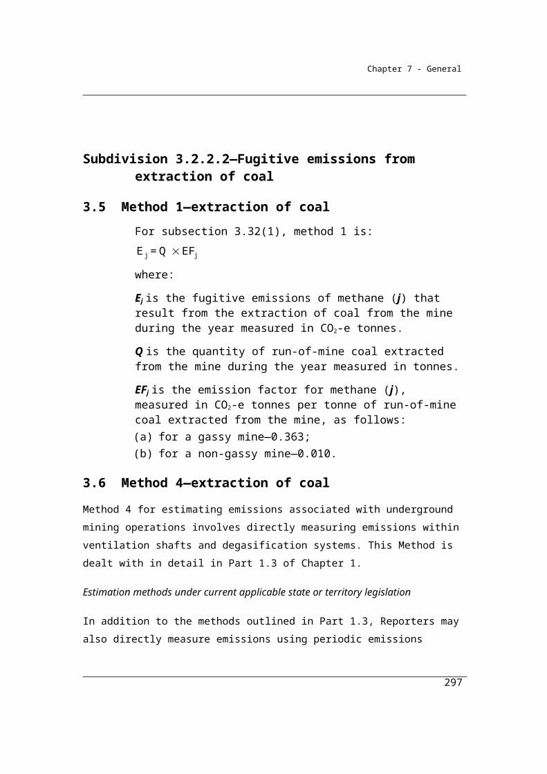
Chapter 7 - General
Division 3.3.7—Natural gas transmissionEmissions may occur as a result of compressor blow downs for maintenance at compressor stations, maintenance on pipelines, leakage and accidents.
Transmission mains are defined as high-pressure pipelines greater than 1050 kilopascals, as used in the Energy Supply Association of Australia natural gas statistics.
Note that in this part the definition of natural gas is as follows:
natural gas includes coal seam methane that is captured for combustion where
the production of coal is not intended to occur
3.74 Application
This Division applies to fugitive emissions from natural gas transmission activities.
3.75 Available methods
(1) Subject to section 1.18 and subsection (2), one of the following methods must be used for estimating fugitive emissions of each gas type, being carbon dioxide and methane, released from the operation of a facility that is constituted by natural gas transmission through a system of pipelines during a year:
(a) method 1 under section 3.76;(b) method 2 under section 3.77.
Note: There is no method 3 or 4 for this Division.
(2) However, for incidental emissions another method may be used that is consistent with the principles in section 1.13.
297
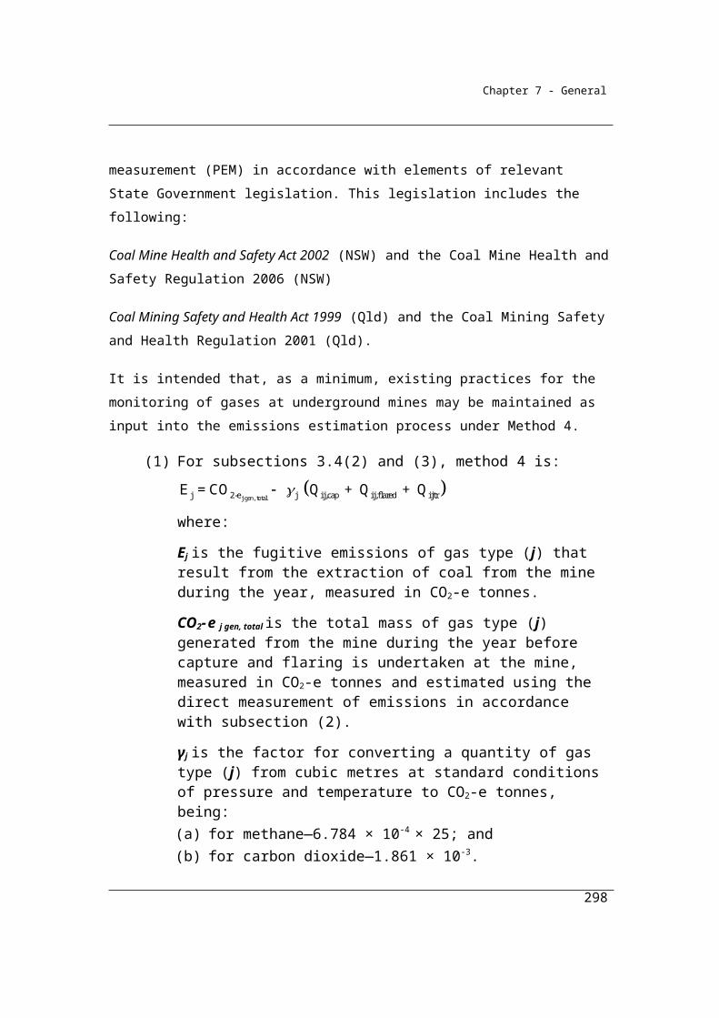
Chapter 7 - General
Summary of available methods, for estimating emissions from natural gas transmission, by emissions of gas type (j)
CO2 CH4 N2O
Method 1 Section 3.76 Section 3.76 NO
Method 2 Section 3.77 Section 3.77 NO
Method 3 NO NA NO
Method 4 NO NA NO
NA = Not available. NO = Not occurring
3.76 Method 1—natural gas transmission
Method 1 is:
ij i ijE = Q EF
where:
Eij is the fugitive emissions of gas type (j) from natural gas transmission through a system of pipelines of length (i) during the year measured in CO2-e tonnes.
Qi is the length of the system of pipelines (i) measured in kilometres.
EFij is the emission factor for gas type (j), which is 0.02 for carbon dioxide and 10.4 for methane, measured in tonnes of CO2-e emissions per kilometre of pipeline (i).
Example
A company has a network of natural gas transmission pipelines with a total length of 3600 km, over a year. The Reporter elects to use Method 1 to calculate fugitive emissions from natural gas transmission, for carbon dioxide and methane. Emissions are estimated as follows:
where:
298
Eij = Qi EFij
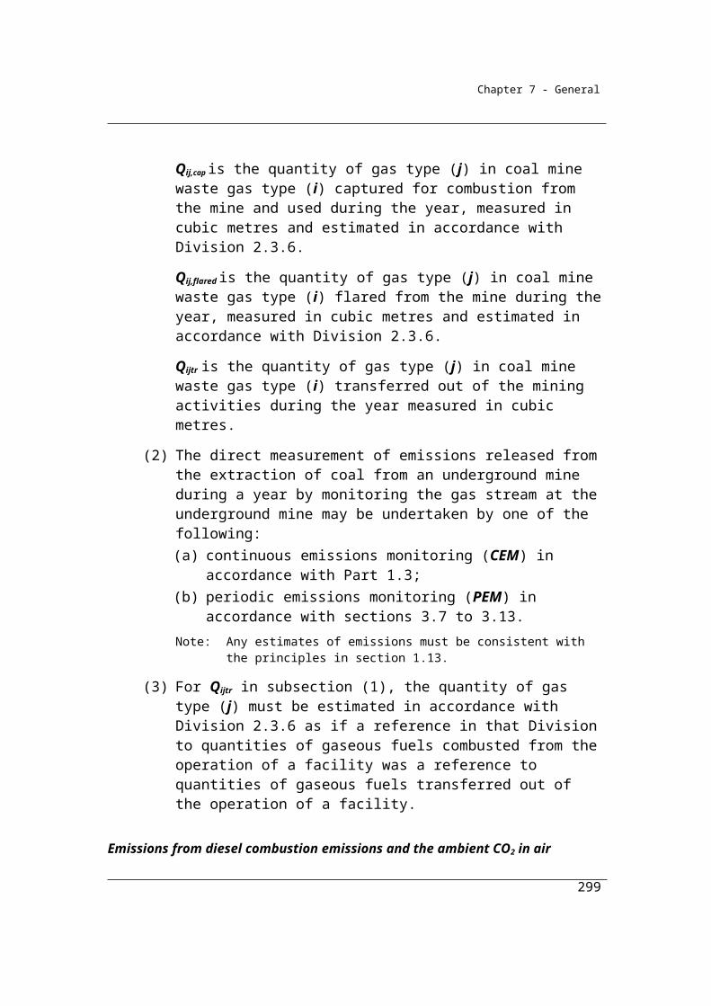
Chapter 7 - General
Eij is the emissions measured in CO2 e tonnes of gas type (j), being either carbon dioxide or methane, released from natural gas transmission through a system of pipelines of length (i) during the year measured in CO2-e tonnes.
Qi is the length of the system of pipelines (i) measured in kilometres. In this case pipeline length is 3600 km.
EFij is the emission factor for gas type (j) being 0.02 for carbon dioxide and 8.7 for methane measured in tonnes of CO2 e emissions per kilometre of pipeline (i).
Therefore, to estimate greenhouse gas emissions (from carbon dioxide and methane) in CO2-e tonnes:
For carbon dioxide
=3600 x 0.02
Total emissions of carbon dioxide = 72 t CO2-e
For methane
=3600 x 10.4
Total emissions of methane = 37,440 t CO2-e
3.77 Method 2—natural gas transmission
Method 2 for fugitive emissions from natural gas transmission requires the use of equipment-specific emission factors and more detail on the types of equipment used at the facility. The Method is intended to be as specified in the American Petroleum Institute’s Compendium of Greenhouse Gas Emissions Estimation Methodologies for the Oil and Natural Gas Industry 2009 sections 5 and 6.1.2. The option is also provided to refine the emission factors from information on the composition of the gases, using the engineering calculations and from information on the leakage rates for specific pipeline materials for the industry.
(1) Method 2 is:
j k k jkE = (Q EF )
where:
299
Chapter 7 - General
Ej is the fugitive emissions of gas type (j) measured in CO2-e tonnes from the natural gas transmission through the system of pipelines during the year.
Σk is the total of emissions of gas type (j) measured in CO2-e tonnes and estimated by summing up the emissions released from each equipment type (k) listed in sections 5 and 6.1.2 of the API Compendium, if the equipment is used in the natural gas transmission.
Qk is the total of the quantities of natural gas measured in tonnes that pass through each equipment type (k) or the number of equipment units of type (k) listed in sections 5 and 6.1.2 of the API Compendium, if the equipment is used in the natural gas transmission.
EFjk is the emission factor of gas type (j) measured in CO2-e tonnes for each equipment type (k) listed in sections 5 and 6.1.2 of the API Compendium, where the equipment is used in the natural gas transmission.
(2) For EFjk, the emission factors for a gas type (j) as the natural gas passes through the equipment type (k) are:
(a) as listed in sections 5 and 6.1.2 of the API Compendium, for the equipment type; or
(b) as listed in that Compendium for the equipment type with emission factors adjusted for variations in estimated gas composition, in accordance with that Compendium’s sections 5 and 6.1.2, and the requirements of Division 2.3.3; or
(c) as listed in that Compendium for the equipment type with emission factors adjusted for variations in the type of equipment material estimated in accordance with the results of published research for the crude oil industry and the principles of section 1.13; or
(d) if the manufacturer of the equipment supplies equipment-specific emission factors for the equipment type—those factors; or
(e) estimated using the engineering calculation approach in accordance with sections 5 and 6.1.2 of the API Compendium.
Note: The API Compendium is available at www.api.org.
300
Chapter 7 - General
Division 3.3.8—Natural gas distributionEmissions arise for this category from fugitive sources (for example gas leaks, accidental releases). The boundary between natural gas transmission and distribution is generally taken to be the city gate regulator stations at which gas pressures are reduced from transmission pressures to sub-transmission pressures. For the purposes of this methodology, natural gas distribution comprises low, medium and high-pressure reticulation ≤ 1050 kilopascals.
Other sources of emissions arising from the natural gas distribution, such as from the combustion of fuels for energy, are not described in this chapter and must be estimated using the Methods described in other chapters.
Note that in this part the definition of natural gas is as follows:
natural gas includes coal seam methane that is captured for combustion where
the production of coal is not intended to occur
3.78 Application
This Division applies to fugitive emissions from natural gas distribution activities.
3.79 Available methods
(1) Subject to section 1.18 and subsection (2), one of the following methods must be used for estimating fugitive emissions of each gas type, being carbon dioxide and methane, released during a year from the operation of a facility that is constituted by natural gas distribution through a system of pipelines:
(a) method 1 under section 3.80;(b) method 2 under section 3.81.
Note: There is no method 3 or 4 for this Division.
(2) However, for incidental emissions another method may be used that is consistent with the principles in section 1.13.
301

Chapter 7 - General
Summary of available methods, for estimating emissions from natural gas distribution, by emissions of gas type (j)
CO2 CH4 N2O
Method 1 Section 3.80 Section 3.80 NO
Method 2 Section 3.81 Section 3.81 NO
Method 3 NA NA NO
Method 4 NA NA NO
NA = Not available. NO = Not occurring
3.80 Method 1—natural gas distribution
Method 1 for fugitive emissions from natural gas distribution is derived from the National Greenhouse Accounts.
(1) Method 1 is:
jp p p jp E S %UAG 0.55 C
where:
Ejp is the fugitive emissions of gas type (j) that result from natural gas distribution through a system of pipelines with sales of gas in a State or Territory (p) during the year, measured in CO2-e tonnes.
Sp is the total sales during the year from the pipeline system in a State or Territory (p), measured in terajoules.
%UAGp is the percentage of unaccounted for gas in the pipeline system in a State or Territory, relative to the amount of gas issued annually by gas utilities in that State or Territory.Note: The value 0.55 following the variable %UAGp in method 1 represents the
proportion of gas that is unaccounted for and released as emissions.
302
Chapter 7 - General
Cjp is the natural gas composition factor for gas type (j) for the natural gas supplied from the pipeline system in a State or Territory (p), measured in CO2-e tonnes per terajoule.
(2) For %UAGp in subsection (1), column 3 of an item in the following table specifies the percentage of unaccounted for gas in the pipeline system in a State or Territory specified in column 2 of that item.
(3) For Cjp in subsection (1), columns 4 and 5 of an item in the following table specify the natural gas composition factor for carbon dioxide and methane for a pipeline system in a State or Territory specified in column 2.
Item State Unaccounted for gas (a)%
Natural gas composition factor (a)(tonnes CO2-e/TJ)
UAGp CO2 CH4
1 NSW and ACT 2.2 0.8 3902 VIC 3.0 0.9 3883 QLD 1.7 0.8 3774 WA 2.9 1.1 3645 SA 4.9 0.8 3906 TAS 0.2 0.9 3887 NT 2.2 0.0 314
3.81 Method 2—natural gas distribution
Method 2 for fugitive emissions from natural gas distribution requires the use of equipment-specific emission factors and more detail on the types of equipment used at the facility. The Method is intended to be as specified in the American Petroleum Institute’s Compendium of Greenhouse Gas Emissions Estimation Methodologies for the Oil and Natural Gas Industry 2009 sections 5 and 6.1.2. The option is also provided to refine the emission factors from information on the composition of the gases and from information on the leakage rates for specific pipeline materials for the industry.
(1) Method 2 is:
j k k jk E = (Q EF )
where:
Ej is the fugitive emissions of gas type (j) that result from the natural gas distribution during the year measured in CO2-e tonnes.
303
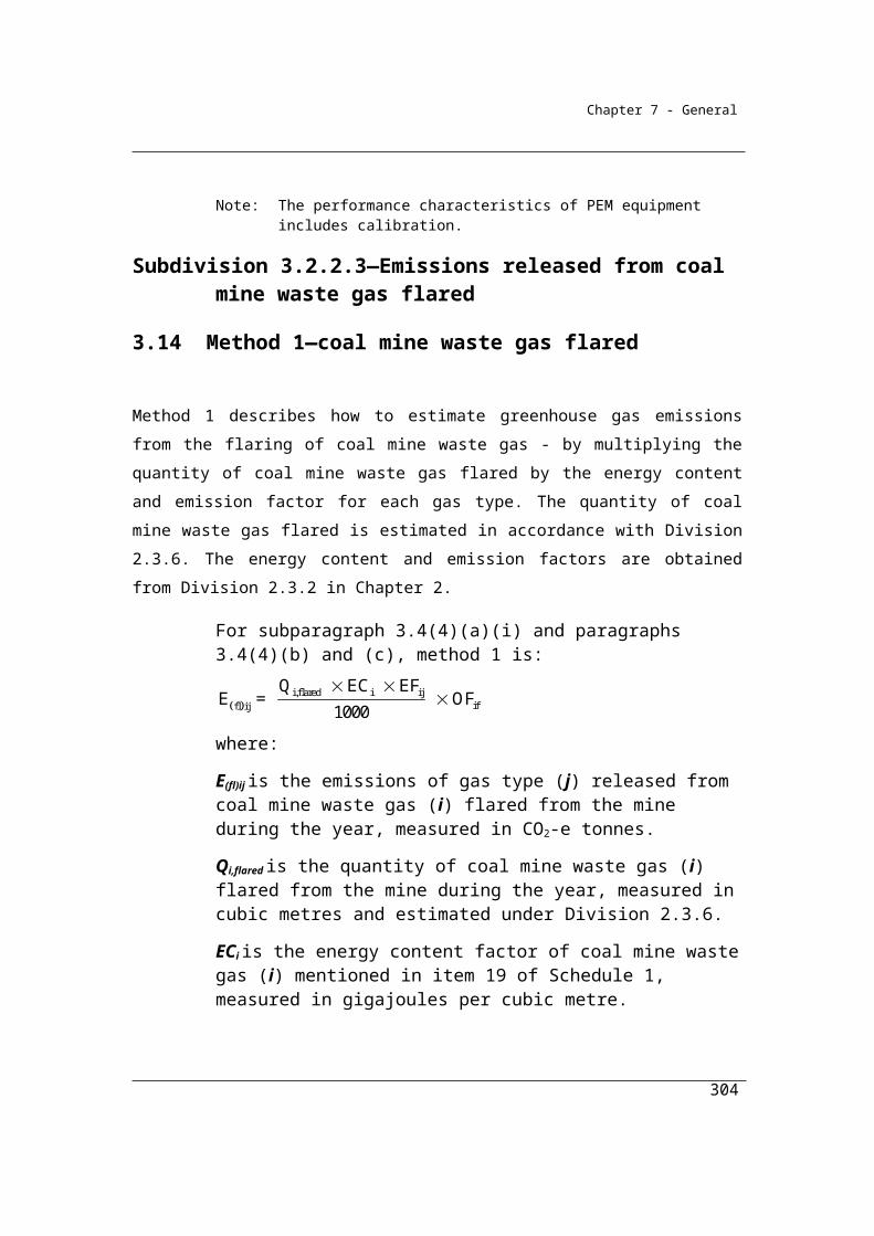
Chapter 7 - General
Σk is the total of emissions of gas type (j) measured in CO2-e tonnes and estimated by summing up the emissions from each equipment type (k) listed in sections 5 and 6.1.2 of the API Compendium, if the equipment is used in the natural gas distribution.
Qk is the total of the quantities of natural gas measured in tonnes that pass through each equipment type (k) or the number of equipment units of type (k) listed in sections 5 and 6.1.2 of the API Compendium, if the equipment is used in the natural gas distribution.
EFjk is the emission factor for gas type (j) measured in CO2-e tonnes for each equipment type (k) listed in sections 5 and 6.1.2 of the API Compendium, if the equipment is used in the natural gas distribution.
(2) For EFjk, the emission factors for gas type (j) as the natural gas passes through the equipment type (k) are:
(a) as listed in sections 5 and 6.1.2 of the API Compendium; or(b) as listed in that Compendium for the equipment type with emission
factors adjusted for variations in estimated gas composition, in accordance with that Compendium’s Sections 5 and 6.1.2, and the requirements of Division 2.3.3; or
(c) as listed in that Compendium for the equipment type with emission factors adjusted for variations in the type of equipment material using adjusted factors; or
(d) if the manufacturer of the equipment supplies equipment-specific emission factors for the equipment type—those factors.
(3) In paragraph 3.81(2)(c), a reference to factors adjusted is a reference to the factors in Table 5-3 of the publication entitled Greenhouse Gas Emission Estimation Methodologies, Procedures and Guidelines for the Natural Gas Distribution Sector, American Gas Association, April 2008, that are adjusted for variations in estimated gas composition in accordance with:
(a) section 5.2.1 of that publication; and(b) Division 2.3.3.
Note that 3.81 (2) (c) allows adjustment of emission factors for variations in the type of material from which the equipment is made. This adjustment is made using Table 5-3 and section 5.2.1 of the publication entitled Greenhouse Gas Emission Estimation Methodologies, Procedures and Guidelines for the Natural Gas Distribution Sector, American Gas Association, April 2008. Table 5-3 includes the emission factors for equipment made from different materials, for example, cast iron
304
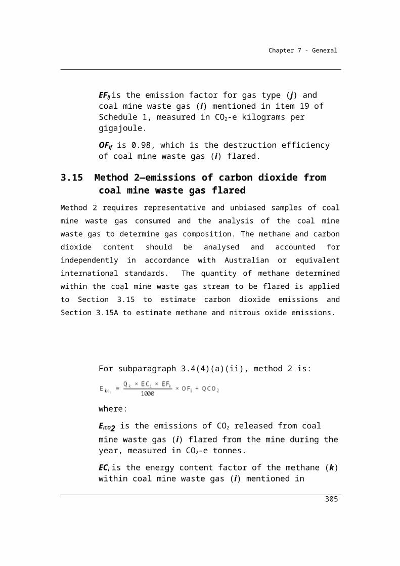
Chapter 7 - General
pipelines or plastic pipelines. Section 5.2.1 provides a description of how to apply the information in Table 5-3.
The publication entitled Greenhouse Gas Emission Estimation Methodologies, Procedures and Guidelines for the Natural Gas Distribution Sector, American Gas Association, April 2008, is available from:
http://www.aga.org/legislative/legislative+advocacy/environmentalinformation/publicenviro/2008/aga+greenhouse+gas+emission+estimation+guidelines+for+the+natural+gas+distribution+sector.htm
305

Chapter 7 - General
Division 3.3.9—Natural gas production or processing (emissions that are vented or flared)
3.82 Application
This Division applies to fugitive emissions from venting or flaring from natural gas production or processing activities, including emissions from:(a) the venting of natural gas; and(b) the venting of waste gas and vapour streams at facilities that are
constituted by natural gas production or processing; and(c) the flaring of natural gas, waste gas and waste vapour streams at
those facilities.
Note that in this part the definition of natural gas is as follows:
natural gas includes coal seam methane that is captured for combustion where
the production of coal is not intended to occur
3.83 Available methods
(1) Subject to section 1.18, for estimating emissions (emissions that are vented or flared) released during a year from the operation of a facility that is constituted by natural gas production and processing the methods as set out in this section must be used.
(2) One of the following methods must be used for estimating fugitive emissions that result from deliberate releases from process vents, system upsets and accidents:
(i) method 1 under section 3.84; and(ii) method 4 under Part 1.3.
Note: There is no method 2 or 3 for subsection (2).
(3) For estimating emissions released from gas flared from natural gas production and processing:
(a) one of the following methods must be used for estimating emissions of carbon dioxide released:(i) method 1 under section 3.85;
(ii) method 2 under section 3.86;(iii) method 3 under section 3.87; and
306

Chapter 7 - General
(b) if estimating emissions of methane released—one of the following methods must be used:(i) method 1 under section 3.85;
(ii) method 2A under section 3.86A; and(c) if estimating emissions of nitrous oxide released—one of the
following methods must be used:(i) method 1 under section 3.85;
(ii) method 2A under section 3.86A.Note: The flaring of gas from natural gas production and processing releases
emissions of carbon dioxide, methane and nitrous oxide. The reference to gas type (j) in method 1 in section 3.85 is a reference to these gases. The same formula is used to estimate emissions of each of these gases. There is no method 4 for emissions of carbon dioxide and no method 2, 3 or 4 for emissions of nitrous oxide or methane.
(4) However, for incidental emissions another method may be used that is consistent with the principles in section 1.13.
Summary of available methods, for estimating emissions from natural gas production and processing (emissions that are vented or flared), by emissions of gas type (j)
CO2 CH4 N2O
Deliberate releases from process vents, system upsets and accidents
Method 1 Section 3.84 Section 3.84 NO
Method 2 NA NA NO
Method 3 NA NA NO
Method 4 Method 4 under Part 1.3
Method 4 under Part 1.3
NO
Flaring
Method 1 Section 3.85 Section 3.85 Section 3.85
Method 2 Section 3.86 NA NA
Method 3 Section 3.87 NA NA
NA = Not available. NO = Not occurring
307

Chapter 7 - General
Subdivision 3.3.9.1—Fugitive emissions that result from deliberate releases from process vents, system upsets and accidents
Venting refers to emissions that are the result of processes or equipment design or operational practices. Venting at oil or gas processing facilities is mainly associated with the release of CO2, which is extracted from the raw gas stream in the course of gas processing. Because separation of the other components of the gas stream from the CO2 is incomplete, the vented CO2 contains small quantities of methane.
3.84 Method 1—emissions from system upsets, accidents and deliberate releases from process vents
Method 1 is, for a process mentioned in column 2 of an item in the following table, as described in the section of the API Compendium mentioned in column 3 for the item.
Item Emission process API Compendium section
1 Gas treatment processes Section 5.12 Cold process vents Section 5.33 Natural gas blanketed tank emissions Section 5.4.44 Other venting sources—gas driven pneumatic devices Section 5.6.15 Other venting sources—gas driven chemical injection pumps Section 5.6.26 Other venting sources—coal seam exploratory drilling, well
testing and mud degassingSection 5.6.3 and 5.6.6
7 Non-routine activities—production related non-routine emissions
Section 5.7.1 or 5.7.2
8 Non-routine activities—gas processing related non-routine emissions
Section 5.7.1 or 5.7.3
Subdivision 3.3.9.2—Emissions released from gas flared from natural gas production and processing
Flaring refers to the controlled release to combustion of a mixed flammable gas stream. At gas processing plants, flared gas may arise from natural gas processing. Where there is no market for gas separated from the wellhead production stream, the gas is reinjected or flared.
308

Chapter 7 - General
This subsector does not include flaring from petroleum refining activities, which should be reported separately under 1.B.2a.iv Crude Oil refining and storage.
Method 1 is derived from the methods used for the National Greenhouse Accounts. Methods 2 and 3 for carbon dioxide rely on the sampling and analysis of the fuel to estimate the composition of the gases in the fuel in accordance with the provisions of chapter 2.
3.85 Method 1—gas flared from natural gas production and processing
(1) Method 1 is:
ij i ijE = Q EF
where:
Eij is the emissions of gas type (j) measured in CO2-e tonnes that result from a fuel type (i) flared in the natural gas production and processing during the year.
Qi is the quantity measured in tonnes of gas flared during the year.
EFij is the emission factor for gas type (j) measured in CO2-e tonnes of emissions per tonne of gas flared (i) in the natural gas production and processing during the year.
(2) For EFij mentioned in subsection (1), columns 3, 4 and 5 of an item in the following table specify the emission factor for fuel type (i) specified in column 2 of that item.
Item fuel type (i) Emission factor of gas type (j) (tonnes CO2-e/tonnes fuel flared)CO2 CH4 N2O
1 gas 2.7 0.1 0.03
3.86 Method 2—gas flared from natural gas production and processing
For subparagraph 3.83(3)(a)(ii), method 2 is:
where:
309

Chapter 7 - General
EiCO2 is the fugitive emissions of CO2 from fuel type (i) flared in the natural gas production and processing during the year, measured in CO2-e tonnes.
Qh is the total quantity of hydrocarbons (h) within the fuel type (i) in the natural gas production and processing during the year, measured in tonnes in accordance with Division 2.3.3.
EFhi is the carbon dioxide emission factor for the total hydrocarbons (h) within the fuel type (i) in the natural gas production and processing during the year, measured in CO2-e tonnes per tonne of fuel type (i) flared, estimated in accordance with Division 2.3.3.
OFi is 0.98, which is the destruction efficiency of fuel type (i) flared.
QCO2 is the quantity of CO2 within the fuel type (i) in the natural gas production and processing during the year, measured in CO2-e tonnes in accordance with Division 2.3.3.
3.86A Method 2A—natural gas production and processing (flared methane or nitrous oxide emissions)
For subparagraphs 3.83(3)(b)(ii) and (c)(ii), method 2A is:
where:
EFhij is the emission factor of gas type (j), being methane or nitrous oxide, for the total hydrocarbons (h) within the fuel type (i) in natural gas production and processing during the year, mentioned for the fuel type in the table in subsection 3.85(2) and measured in CO2-e tonnes per tonne of the fuel type (i) flared.
Eij is the fugitive emissions of gas type (j), being methane or nitrous oxide, from fuel type (i) flared from natural gas production and processing during the year, measured in CO2-e tonnes.
OFi is 0.98, which is the destruction efficiency of fuel type (i) flared.
Qh is the total quantity of hydrocarbons (h) within the fuel type (i) in natural gas production and processing during the year, measured in tonnes in accordance with Division 2.3.3.
310

Chapter 7 - General
3.87 Method 3—gas flared from natural gas production and processing
For subparagraph 3.83(3)(a)(iii), method 3 is the same as method 2 under section 3.86, but the emission factor (EFij) must be determined in accordance with method 3 for the consumption of gaseous fuels as specified in Division 2.3.4.
Estimating Carbon dioxide emissions from natural gas production and
processing flaring using Method 2
Natural gas production and processing generally involves some flaring of a waste gas
stream. In this example a facility flares a waste gas stream of 1,000 tonnes during the
year, which contains a relatively high content of carbon dioxide in addition to some
hydrogen sulphide and hydrocarbons. The reporters have chosen to use method 2 as
this approach provides the opportunity to develop a carbon dioxide emission factor
that better reflects the hydrocarbons present in the gas stream, as well as account for
the in-situ carbon dioxide quantity which is emitted, but not combusted in the flare.
Calculate the carbon dioxide emissions using Method 2 in section 3.86 of NGER
(Measurement) Determination
Eico2 = (Qh × EFh × OFi ) + QCO2
Where:
EiCO2 is the fugitive emissions of CO2 from fuel type (i) flared in natural gas production
and processing during the year, measured in CO2-e tonnes.
Qh is the total quantity of hydrocarbons (h) within the fuel type (i) in natural gas
production and processing during the year, measured in tonnes in accordance with
Division 2.3.3.
311

Chapter 7 - General
QCO2 is the quantity of CO2 within the fuel type (i) in natural gas production and
processing during the year, measured in CO2-e tonnes in accordance with Division 2.3.3.
In this example it was determined (in accordance with Division 2.3.3) that the average
composition of the waste gas stream being flared during the year is as follows:
Hydrocarbons C1 to C5 = 0.78 tonnes/ tonne of waste gas stream
Hydrogen sulphide = 0.0.04 tonnes/ tonne of waste gas stream
Nitrogen = 0.08 tonnes/ tonne of waste gas stream
Carbon dioxide = 0.10 tonnes/ tonne of waste gas stream
Therefore:
Qh = 0.78 x 1000 t of waste gas stream flared during the year
Qh = 780 tonnes
QCO2 = 0.10 x 1000 t of waste gas stream flared during the year
QCO2 = 100 tonnes
EFh is the emission factor for the total hydrocarbons (h) within the fuel type (i) in
natural gas production and processing during the year, measured in CO2-e
tonnes per tonne of fuel type (i) flared, estimated in accordance with method 2 in
Division 2.3.3.
In this example it was determined (in accordance with Division 2.3.3) that the emission
factor derived from the average hydrocarbon composition of the waste gas stream
being flared during the year was:
2.2 tonnes of CO2 per tonne of waste gas stream flared
312
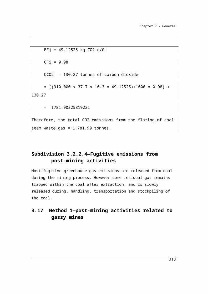
Chapter 7 - General
Therefore:
EFh = 2.2
OFi is 0.98, which is the correction factor for the oxidation of fuel type (i) flared.
To calculate the CO2 emissions from waste gas flared:
= (780 x 2.2 x 0.98) + 100 = 1,781.7
Therefore, the total emissions from the source = 1,782 tonnes
313

Chapter 7 - General
Part 3.4—Carbon capture and storage—fugitive emissions
Division 3.4.1—Preliminary
3.88 Outline of Part
This Part provides for fugitive emissions from carbon capture and storage.
Division 3.4.2—Transport of captured carbon dioxide
Subdivision 3.4.2.1—Preliminary
3.89 Application
This Division applies to fugitive emissions from the transport of carbon dioxide captured for permanent storage.Note: Section 1.19A defines when carbon dioxide is captured for permanent storage.
3.90 Available methods
(1) Subject to section 1.18, for estimating emissions released during a year from the operation of a facility that is constituted by the transport of carbon dioxide captured for permanent storage the methods as set out in this section must be used.
Emissions from transport of carbon dioxide involving transfer
(2) If the carbon dioxide is transferred to a relevant person for injection in accordance with the legislation mentioned in section 1.19A for the person, method 1 under section 3.91 must be used for estimating fugitive emissions of carbon dioxide that result from the transport of the carbon dioxide for that injection.
Emissions from transport of carbon dioxide not involving transfer
(3) If:(a) the carbon dioxide is captured by a relevant person for injection in
accordance with the legislation mentioned in section 1.19A for the person; and
314
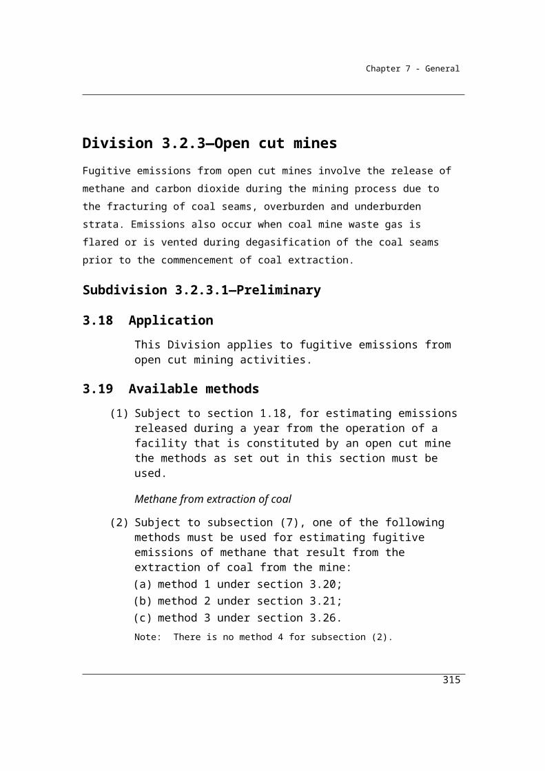
Chapter 7 - General
(b) the carbon dioxide is not transferred to another person for the purpose of injection;
then method 1 under section 3.92 must be used for estimating fugitive emissions of carbon dioxide that result from the transport of the carbon dioxide for that injection.Note: There is no method 2, 3 or 4 for subsections (2) and (3).
(4) However, for incidental emissions another method may be used that is consistent with the principles in section 1.13.
Subdivision 3.4.2.2—Emissions from transport of carbon dioxide captured for permanent storage involving transfer
3.91 Method 1—emissions from transport of carbon dioxide involving transfer
For subsection 3.90(2), method 1 is:
2 2CO CO injE (RCCS Q )
where:
ECO2 is the emissions of carbon dioxide during the year from transportation of carbon dioxide captured for permanent storage to the storage site, measured in CO2-e tonnes.
γ is the factor 1.861 × 10⁻³ for converting a quantity of carbon dioxide from cubic metres at standard conditions of pressure and temperature to CO2-e tonnes.
RCCSCO2 is the quantity of carbon dioxide transferred during the year worked out under Division 1.2.3 and measured in cubic metres at standard conditions of pressure and temperature.
Qinj is the quantity of carbon dioxide injected into the storage site during the year and measured in cubic metres at standard conditions of pressure and temperature.
315
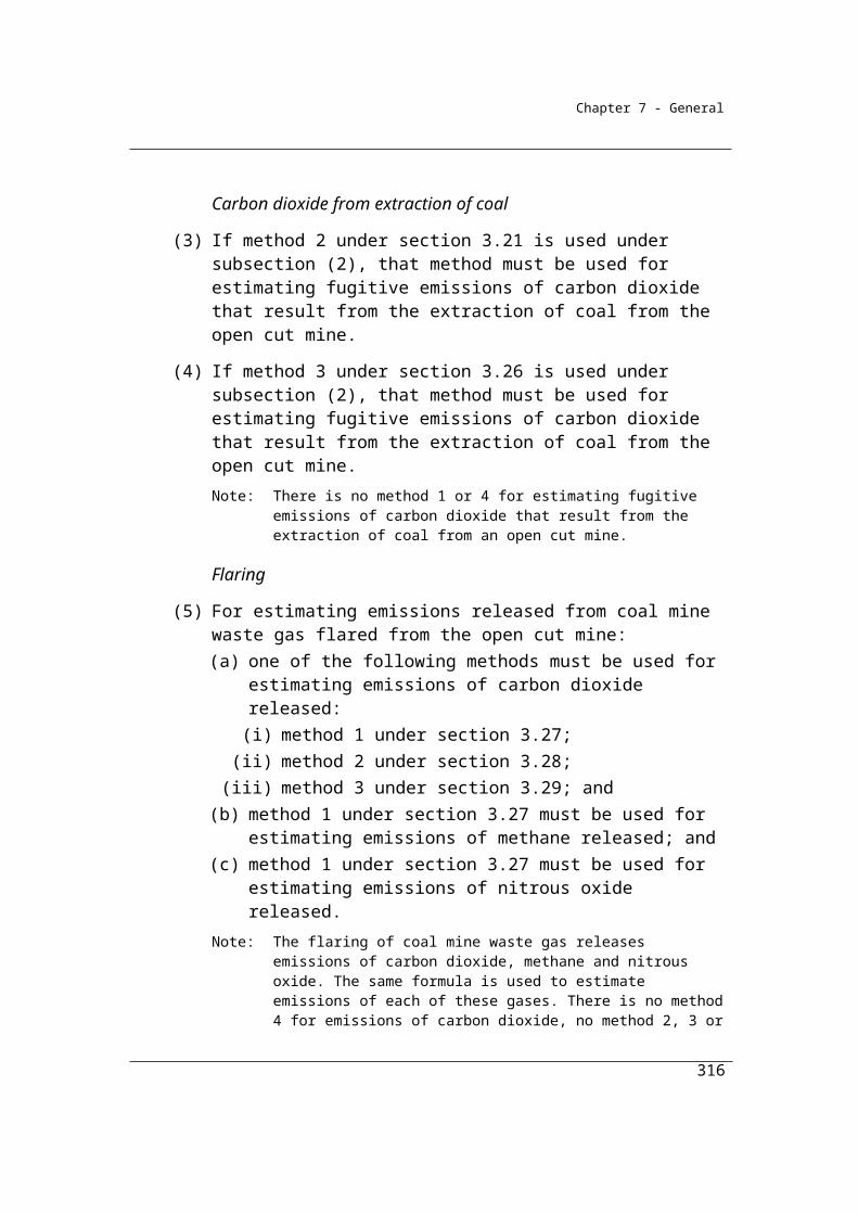
Chapter 7 - General
Subdivision 3.4.2.2—Emissions from transport of carbon dioxide captured for permanent storage not involving transfer
3.92 Method 1—emissions from transport of carbon dioxide not involving transfer
For subsection 3.90(3), method 1 is:
2 2CO CO injE (RCCS Q )
where:
ECO2 is the emissions of carbon dioxide during the year from transportation of carbon dioxide captured for permanent storage to the storage site, measured in CO2-e tonnes.
γ is the factor 1.861 × 10⁻³ for converting a quantity of carbon dioxide from cubic metres at standard conditions of pressure and temperature to CO2-e tonnes.
RCCSCO2 is the quantity of carbon dioxide captured during the year worked out under Division 1.2.3 and measured in cubic metres at standard conditions of pressure and temperature.
Qinj is the quantity of carbon dioxide injected into the storage site during the year and measured in cubic metres at standard conditions of pressure and temperature.
316

Chapter 7 - General
Chapter 4—Industrial processes emissions
Part 4.1—Preliminary
Industrial process emissions are an important source of emissions in Australia and are generated from a wide variety of activities. The principal processes that lead to industrial process emissions include:
1. Mineral Products—generated mainly from the consumption (heating) of carbonate materials (such as limestone) and from within processes that generate carbon dioxide from the use of carbonates;
2. Chemical Industry—generated mainly by the use of fuels as a feedstock or reductant;
3. Metal Products—generated principally from the use of fuels such as coke as carbon reductants and also including perfluorocarbons released from aluminium metal production;
4. Synthetic gas emissions —the release of hydrofluorocarbons and sulphur hexafluoride either as fugitive emissions or leakages from the use of these gases as (for example) refrigerants.
Other sources of emissions released in the course of the production, such as from the combustion of fuels for energy, are not described in this chapter and must be estimated using the Methods described in other chapters.
Full details of industries covered in this chapter are given in section 4.1.
4.1 Outline of Chapter
(1) This Chapter provides for emissions from:(a) the consumption of carbonates; or(b) the use of fuels as:
(i) feedstock; or(ii) carbon reductants;from sources that are industrial processes mentioned in subsection (2).
317
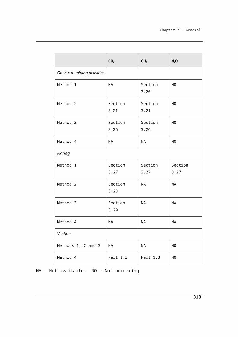
Chapter 7 - General
(2) For subsection (1), the industrial processes are as follows:(a) in Part 4.2:
(i) producing cement clinker (see Division 4.2.1);(ii) producing lime (see Division 4.2.2);
(iii) using carbonate for the production of a product other than cement clinker, lime or soda ash (see Division 4.2.3);
(iv) using and producing soda ash (see Division 4.2.4);(b) in Part 4.3—the production of:
(i) ammonia (see Division 4.3.1);(ii) nitric acid (see Division 4.3.2);
(iii) adipic acid (see Division 4.3.3);(iv) carbide (see Division 4.3.4);(v) a chemical or mineral product other than carbide using a carbon
reductant or carbon anode (see Division 4.3.5);(vi) sodium cyanide (see Division 4.3.6);
(c) in Part 4.4—the production of:(i) iron and steel (see Division 4.4.1);
(ii) ferroalloy metals (see Division 4.4.2);(iii) aluminium (see Divisions 4.4.3 and 4.4.4);(iv) other metals (see Division 4.4.5).
(3) This Chapter, in Part 4.5, also applies to emissions released from the consumption of the following synthetic gases:
(a) hydrofluorocarbons;(b) sulphur hexafluoride.
(4) This Chapter does not apply to emissions from fuel combusted for energy production.
318
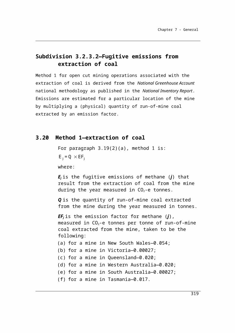
Chapter 7 - General
Part 4.2—Industrial processes—mineral productsThis Part applies to any industry that generates emissions of carbon dioxide through the consumption of carbonates such as calcium carbonate (limestone) or magnesium carbonate. The consumption of carbonates that does not lead to carbon dioxide emissions (for example, when used as gravel) is not covered by the scope of these Guidelines.
In order to deduct carbon dioxide captured for permanent storage reporters are required to use Method 2 or higher. These higher order methods provide a more accurate estimate of the carbon dioxide emissions than under Method 1, the default method. As the carbon dioxide captured is deducted from the emissions estimate it is necessary to have a greater level of accuracy in the emissions estimate than is achieved using Method 1.
Division 4.2.1—Cement clinker productionCarbon dioxide is generated during the production of clinker, an intermediate product from which cement is made. The manufacture of cement involves a multi-stage process whereby calcium carbonate (CaCO3) from calcium rich raw materials such as limestone, chalk and natural cement rock is heated at temperatures of approximately 1500 °C in cement kilns to form lime (CaO) and CO2. In addition to CaCO3, the raw materials used in cement production may also contain small quantities of magnesium
carbonate (MgCO3). On heating, MgCO3 also decomposes to generate CO2. Some clinker manufacturers also use materials containing lime and magnesium oxide as inputs into their process which can reduce the amount of CO2 generated by that facility.
It is intended that the parameters Fcal and Fckd in methods 1, 2 and 3 in this division, be estimated by industry based on the principles of Section 1.13, namely transparency, comparability, accuracy and completeness. Where actual data for these is not available it is assumed that, at the temperatures and residence times achieved in cement (clinker) kilns, the degree of calcination achieved for all material incorporated in the clinker is 100 percent.
319

Chapter 7 - General
4.2 Application
This Division applies to cement clinker production.
4.3 Available methods
(1) Subject to section 1.18, one of the following methods must be used for estimating emissions of carbon dioxide released during a year from the operation of a facility that is constituted by the production of cement clinker:
(a) method 1 under section 4.4;(b) method 2 under section 4.5;(c) method 3 under section 4.8;(d) method 4 under Part 1.3.
(2) However, for incidental emissions, another method may be used that is consistent with the principles in section 1.13.
Summary of available methods, for estimating emissions from cement production, by emissions of gas type (j)
CO2 CH4 N2O
Method 1 Section 4.4 NO NO
Method 2 Section 4.5 NO NO
Method 3 Section 4.8 NO NO
Method 4 Part 1.3 NO NO
NO = Not occurring
4.4 Method 1—cement clinker production
Method 1 for the production of cement clinker is derived from the National Greenhouse Account national methodology as published in the National Inventory Report. It involves the collection of data on the quantities of cement clinker and cement kiln dust produced and the use of the specified emission factors for cement clinker and carbon-bearing non-fuel raw material.
Method 1 is:
320
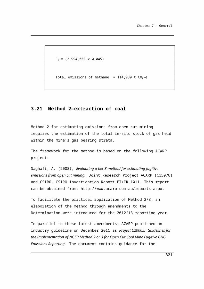
Chapter 7 - General
ij ij toc,j i ckd ckdE = EF + EF A + A F
where:
Eij is the emissions of carbon dioxide (j) released from the production of cement clinker (i) during the year measured in CO2-e tonnes.
EFij is 0.534, which is the carbon dioxide (j) emission factor for cement clinker (i), measured in tonnes of emissions of carbon dioxide per tonne of cement clinker produced.
EFtoc,j is 0.010, which is the carbon dioxide (j) emission factor for carbon-bearing non-fuel raw material, measured in tonnes of emissions of carbon dioxide per tonne of cement clinker produced.
Ai is the quantity of cement clinker (i) produced during the year measured in tonnes and estimated under Division 4.2.5.
Ackd is the quantity of cement kiln dust produced as a result of the production of cement clinker during the year, measured in tonnes and estimated under Division 4.2.5.
Fckd is:(a) the degree of calcination of cement kiln dust produced as a result of
the production of cement clinker during the year, expressed as a decimal fraction; or
(b) if the information mentioned in paragraph (a) is not available—the value 1.
4.5 Method 2—cement clinker production
Method 2 requires the derivation of more accurate, facility-specific emission factors to generate more accurate estimates of emissions of carbon dioxide from the production process. It utilises sampling and analysis of the clinker outputs to estimate the composition of its contents and, from an understanding of the chemical reactions involved in the calcination, the derivation of facility-specific emission factors. The fractions of calcium oxide and magnesium oxide in subsection (2) should not include the calcium oxide and magnesium oxide that enters the process in the raw materials.
(1) Method 2 is:
2ij ij toc,j i ckd ckd coE EF EF A +A × F RCCS
where:
321
Chapter 7 - General
Eij is the emissions of carbon dioxide (j) released from the production of cement clinker (i) during the year measured in CO2-e tonnes.
EFij is as set out in subsection (2).
EFtoc,j is 0.010, which is the carbon dioxide (j) emission factor for carbon-bearing non-fuel raw material, measured in tonnes of emissions of carbon dioxide per tonne of cement clinker produced.
Ai is the quantity of cement clinker (i) produced during the year measured in tonnes and estimated under Division 4.2.5.
Ackd is the quantity of cement kiln dust produced as a result of the production of cement clinker during the year, measured in tonnes and estimated under Division 4.2.5.
Fckd is:(a) the degree of calcination of cement kiln dust produced as a result of
the production of cement clinker during the year, expressed as a decimal fraction; or
(b) if the information mentioned in paragraph (a) is not available—the value 1.
γ is the factor 1.861 × 10⁻³ for converting a quantity of carbon dioxide from cubic metres at standard conditions of pressure and temperature to CO2-e tonnes.
RCCSCO2 is carbon dioxide captured for permanent storage measured in cubic metres in accordance with Division 1.2.3.
(2) For subsection (1), EFij is:
CaO MgO0.785 1.092F × + F ×
where:
FCaO is the estimated fraction of cement clinker that is calcium oxide derived from carbonate sources and produced from the operation of the facility.
FMgO is the estimated fraction of cement clinker that is magnesium oxide derived from carbonate sources and produced from the operation of the facility.Note: The molecular weight ratio of carbon dioxide to calcium oxide is 0.785, and
the molecular weight ratio of carbon dioxide to magnesium oxide is 1.092.
322

Chapter 7 - General
(3) The cement clinker must be sampled and analysed in accordance with sections 4.6 and 4.7.
4.6 General requirements for sampling cement clinker
(1) A sample of cement clinker must be derived from a composite of amounts of the cement clinker produced.
(2) The samples must be collected on enough occasions to produce a representative sample.
(3) The samples must also be free of bias so that any estimates are neither over nor under estimates of the true value.
(4) Bias must be tested in accordance with an appropriate standard.Note: An appropriate standard is AS 4264.4—1996, Coal and coke – Sampling
Part 4: Determination of precision and bias.
(5) The value obtained from the sample must only be used for the production period for which it was intended to be representative.
4.7 General requirements for analysing cement clinker
(1) Analysis of a sample of cement clinker, including determining the fraction of the sample that is calcium oxide or magnesium oxide, must be done in accordance with industry practice and must be consistent with the principles in section 1.13.
(2) The minimum frequency of analysis of samples of cement clinker must be in accordance with the Tier 3 method for cement clinker in section 2.2.1.1 in Chapter 2 of Volume 3 of the 2006 IPCC Guidelines.
4.8 Method 3—cement clinker production
Method 3 is based on the Tier 3 approach in the 2006 IPCC Guidelines for National Greenhouse Inventories which utilises information on the purity of the carbonate inputs. This method requires sampling and analysis of the raw materials to determine the qualities that affect emission levels such as the raw material’s pure
carbonate content.
(1) Method 3 is:
323
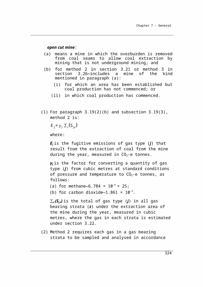
Chapter 7 - General
Step 1 Measure the amount of emissions of carbon dioxide in CO2-e tonnes released from each pure carbonate calcined in the production of cement clinker during the year as follows:
2ij ij i cal ckd ckd ckd toc toc coE = EF Q F A EF 1 F + Q EF RCCS
where:
Eij is the emissions of carbon dioxide (j) released from the carbonate (i) calcined in the production of cement clinker during the year measured in CO2-e tonnes.
EFij is the carbon dioxide (j) emission factor for the carbonate (i) measured in tonnes of emissions of carbon dioxide per tonne of pure carbonate, as follows:(a) for calcium carbonate—0.440; and(b) for magnesium carbonate—0.522; and(c) for dolomite—0.477; and(d) for any other pure carbonate — the factor for the carbonate in
accordance with section 2.1 of Chapter 2 of Volume 3 of the 2006 IPCC Guidelines.
Qi is the quantity of the pure carbonate (i) consumed in the calcining process for the production of cement clinker during the year measured in tonnes and estimated under Division 4.2.5.
Fcal is:(a) the amount of the carbonate calcined in the production of
cement clinker during the year, expressed as a decimal fraction; or
(b) if the information mentioned in paragraph (a) is not available—the value 1.
Ackd is the quantity of cement kiln dust lost from the kiln in the production of cement clinker during the year measured in tonnes and estimated under Division 4.2.5.
EFckd is 0.440, which is the carbon dioxide emission factor for calcined cement kiln dust lost from the kiln.
Fckd is:(a) the fraction of calcination achieved for cement kiln dust lost
from the kiln in the production of cement clinker during the year; or
(b) if the information mentioned in paragraph (a) is not available—the value 1.
324
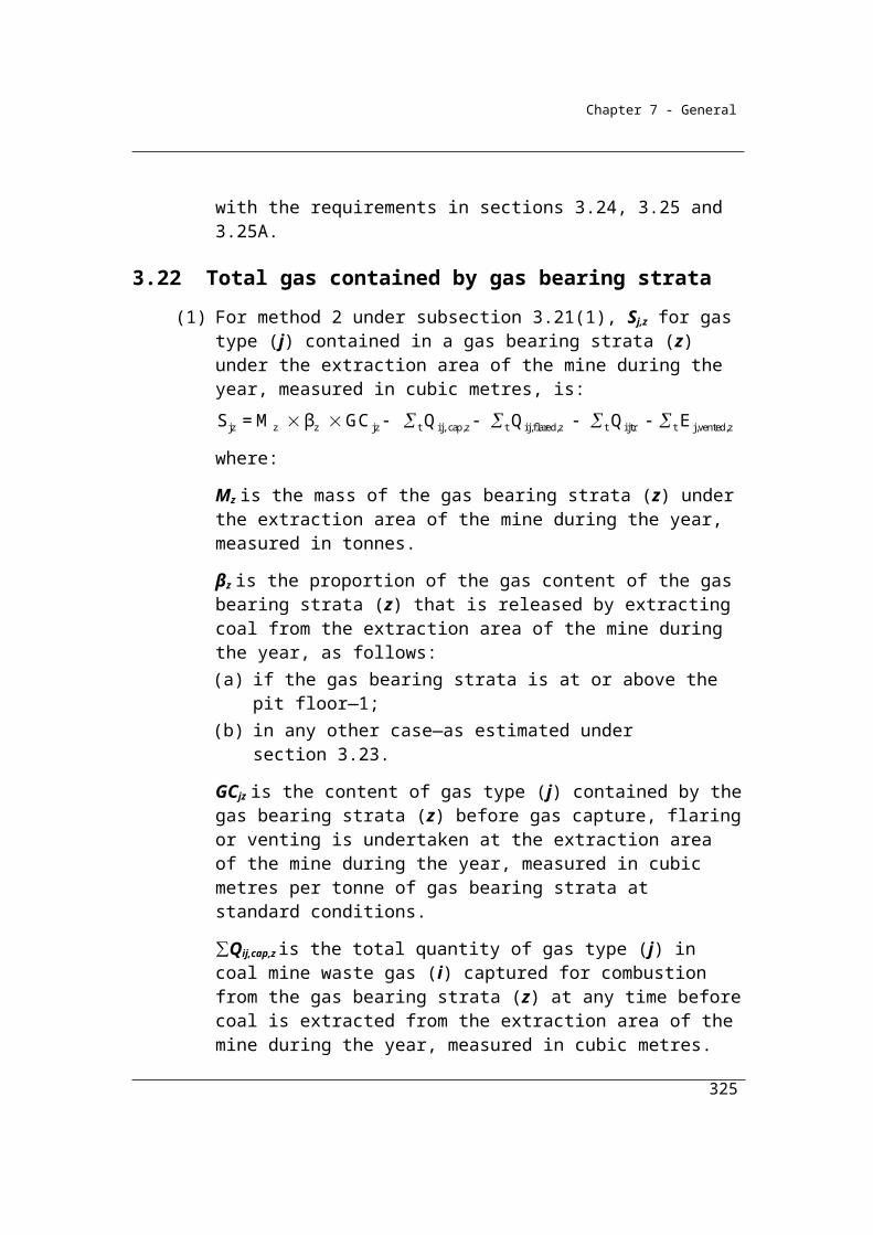
Chapter 7 - General
Qtoc is the quantity of total carbon-bearing non-fuel raw material consumed in the production of cement clinker during the year measured in tonnes and estimated under Division 4.2.5.
EFtoc is 0.010, which is the emission factor for carbon-bearing non-fuel raw material, measured in tonnes of carbon dioxide produced per tonne of carbon.
γ is the factor 1.861 × 10⁻³ for converting a quantity of carbon dioxide from cubic metres at standard conditions of pressure and temperature to CO2-e tonnes.
RCCSCO2 is carbon dioxide captured for permanent storage measured in cubic metres in accordance with Division 1.2.3.
Step 2 Add together the amount of emissions of carbon dioxide as measured in CO2-e tonnes released for each pure carbonate calcined in the production of cement clinker during the year.
(2) For the factor EFckd in subsection (1), the carbon dioxide emission factor for calcined cement kiln dust is assumed to be the same as the emission factor for calcium carbonate.
(3) For the factor Qtoc in subsection (1), the quantity of carbon-bearing non-fuel raw material must be estimated in accordance with Division 4.2.5 as if a reference to carbonates consumed from the activity was a reference to carbon-bearing non-fuel raw material consumed from the activity.
(4) Method 3 requires carbonates to be sampled and analysed in accordance with sections 4.9 and 4.10.
4.9 General requirements for sampling carbonates
(1) Method 3 requires carbonates to be sampled in accordance with the procedure for sampling cement clinker specified under section 4.6 for method 2.
(2) In applying section 4.6, a reference in that section to cement clinker is taken to be a reference to a carbonate.
4.10 General requirements for analysing carbonates
(1) Analysis of samples of carbonates, including determining the quantity (in tonnes) of pure carbonate, must be done in accordance with industry
325

Chapter 7 - General
practice or standards, and must be consistent with the principles in section 1.13.
(2) The minimum frequency of analysis of samples of carbonates must be in accordance with the Tier 3 method in section 2.2.1.1 of Chapter 2 of Volume 3 of the 2006 IPCC Guidelines.
326
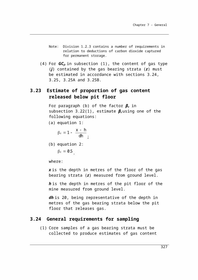
Chapter 7 - General
Division 4.2.2—Lime productionLime is a chemical having major uses in metallurgy and construction. Lime is produced by heating carbonate raw materials in a kiln. During this process, carbon dioxide is emitted.
Lime kiln dust may be produced as part of the lime production process and can be recycled through the system. However at the end of the process some lime kiln dust may still remain. The quantity of kiln dust produced impacts on the emissions estimate and is included as part of the method,
Emissions from the in-house production of lime in the metals industry is estimated under Division 4.2.3.
4.11 Application
This Division applies to lime production (other than the in-house production of lime in the metals industry).
4.12 Available methods
(1) Subject to section 1.18, one of the following methods must be used for estimating emissions of carbon dioxide released during a year from the operation of a facility that is constituted by the production of lime (other than the in-house production of lime in the ferrous metals industry):
(a) method 1 under section 4.13;(b) method 2 under section 4.14;(c) method 3 under section 4.17;(d) method 4 under Part 1.3.
(2) However, for incidental emissions another method may be used that is consistent with the principles in section 1.13.
327
Chapter 7 - General
Summary of available methods, for estimating emissions from lime production, by emissions of gas type (j)
CO2 CH4 N2O
Method 1 Section 4.13 NO NO
Method 2 Section 4.14 NO NO
Method 3 Section 4.17 NO NO
Method 4 Part 1.3 NO NO
NO = Not occurring
4.13 Method 1—lime production
Method 1 for the production of lime is derived from the National Greenhouse Account national methodology as published in the National Inventory Report. It involves the multiplication of the quantity of lime produced by the emission factor for lime.
Lime kiln dust may be produced as part of the lime production process and can be recycled through the system. However at the end of the process some lime kiln dust may still remain. The quantity of kiln dust produced impacts on the emissions estimate and is included as part of the method,
Lime is also produced using varying grades of limestone which contain impurities such as Magnesium Oxide (MgO). For Method 1 estimation, default emission factors have been provided for lime produced using limestone with higher concentrations of MgO.
(1) Method 1 is:
+ ij i lkd lkd ijE A A F EF
where:
Eij is the emissions of carbon dioxide (j) released from the production of lime (i) during the year, measured in CO2-e tonnes.
Ai is the quantity of lime produced during the year, measured in tonnes and estimated under Division 4.2.5.
328
Chapter 7 - General
Alkd is the quantity of lime kiln dust lost as a result of the production of lime during the year, measured in tonnes and estimated under Division 4.2.5.
Flkd is:(a) the fraction of calcination achieved for lime kiln dust in the
production of lime during the year; or(b) if the data mentioned in paragraph (a) is not available—the value 1.
EFij is the carbon dioxide (j) emission factor for lime, measured in tonnes of emission of carbon dioxide per tonne of lime produced, as follows:
(a) for commercial lime production—0.675;(b) for non-commercial lime production—0.730;(c) for magnesian lime and dolomitic lime production—0.860.
(2) In this section:
dolomitic lime is lime formed from limestone containing more than 35% magnesium carbonate.
magnesian lime is lime formed from limestone containing 5–35% magnesium carbonate.
4.14 Method 2—lime production
Method 2 requires the derivation of more accurate, facility-specific emission factors to generate more accurate estimates of emissions of carbon dioxide from the production process. It utilises sampling and analysis of the lime outputs to estimate the composition of its contents and, from an understanding of the chemical reactions involved in the consumption of carbonate (calcination), the derivation of facility-
specific emission factors.
(1) Method 2 is:
2
+ ij i lkd lkd ij coE A A F EF - RCCS
where:
Eij is the emissions of carbon dioxide (j) released from the production of lime (i) during the year, measured in CO2-e tonnes.
Ai is the quantity of lime produced during the year, measured in tonnes and estimated under Division 4.2.5.
329

Chapter 7 - General
Alkd is the quantity of lime kiln dust lost as a result of the production of lime during the year, measured in tonnes and estimated under Division 4.2.5.
Flkd is:(a) the fraction of calcination achieved for lime kiln dust in the
production of lime during the year; or(b) if the data in paragraph (a) is not available—the value 1.
EFij is worked out using the following formula:
ij CaO MgO EF F 0.785 + F 1.092
where:
FCaO is the estimated fraction of lime that is calcium oxide derived from carbonate sources and produced from the operation of the facility.
FMgO is the estimated fraction of lime that is magnesium oxide derived from carbonate sources and produced from the operation of the facility.
γ is the factor 1.861 × 10⁻³ for converting a quantity of carbon dioxide from cubic metres at standard conditions of pressure and temperature to CO2-e tonnes.
RCCSCO2 is carbon dioxide captured for permanent storage, measured in cubic metres in accordance with Division 1.2.3.
(2) Method 2 requires lime to be sampled and analysed in accordance with sections 4.15 and 4.16.
4.15 General requirements for sampling
(1) A sample of lime must be derived from a composite of amounts of the lime produced.Note: Appropriate standards for sampling are:
ASTM C25-06, Standard Test Methods for Chemical Analysis of Limestone, Quicklime, and Hydrated Lime
ASTM C50-00 (2006), Standard Practice for Sampling, Sample Preparation, Packaging, and Marking of Lime and Limestone Products
AS 4489.0–1997 Test methods for limes and limestones—General introduction and list of methods.
(2) The samples must be collected on enough occasions to produce a representative sample.
330
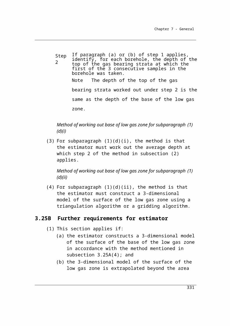
Chapter 7 - General
(3) The samples must also be free of bias so that any estimates are neither over nor under estimates of the true value.
(4) Bias must be tested in accordance with an appropriate standard.Note: An appropriate standard is AS 4264.4—1996 – Coal and coke – sampling –
Determination of precision and bias.
(5) The value obtained from the sample must only be used for the production period for which it was intended to be representative.
4.16 General requirements for analysis of lime
(1) Analysis of a sample of lime, including determining the fractional purity of the sample, must be done in accordance with industry practice and must be consistent with the principles in section 1.13.
(2) The minimum frequency of analysis of samples of lime must be in accordance with the Tier 3 method in section 2.2.1.1 of Chapter 2 of Volume 3 of the 2006 IPCC Guidelines.
4.17 Method 3—lime production
Method 3 is based on the Tier 3 approach in the IPCC Guidelines for National Greenhouse Inventories which utilises information on the purity of the carbonate inputs. This method requires sampling and analysis of the raw materials for qualities that affect emission levels such as the material’s pure carbonate content.
(1) Method 3 is:
Step 1 Measure the amount of emissions of carbon dioxide in CO2-e tonnes released from each pure carbonate calcined in the production of lime during the year as follows:
2lkd coij ij i cal lkd lkd RCCS- E EF Q F A EF 1 F = ( ) ( )
where:
Eij is the emissions of carbon dioxide (j) released from a carbonate (i) calcined in the production of lime during the year measured in CO2-e tonnes.
331
Chapter 7 - General
EFij is the carbon dioxide (j) emission factor for the carbonate (i), measured in tonnes of emissions of carbon dioxide per tonne of pure carbonate as follows:(a) for calcium carbonate—0.440;(b) for magnesium carbonate—0.522;(c) for dolomite—0.477;(d) for any other carbonate—the factor for the carbonate in
accordance with section 2.1 of Chapter 2 of Volume 3 of the 2006 IPCC Guidelines.
Qi is the quantity of the pure carbonate (i) entering the calcining process in the production of lime during the year measured in tonnes and estimated under Division 4.2.5.Fcal is:
(a) the amount of the carbonate calcined in the production of lime during the year expressed as a decimal fraction; or
(b) if the information mentioned in paragraph (a) is not available—the value 1.
Alkd is the quantity of lime kiln dust lost in the production of lime during the year, measured in tonnes and estimated under Division 4.2.5.
EFlkd is 0.440, which is the emission factor for calcined lime kiln dust lost from the kiln.Flkd is:(a) the fraction of calcination achieved for lime kiln dust in the
production of lime during the year; or(b) if the data in paragraph (a) is not available—the value 1.
γ is the factor 1.861 × 10⁻³ for converting a quantity of carbon dioxide from cubic metres at standard conditions of pressure and temperature to CO2-e tonnes.RCCSCO2 is carbon dioxide captured for permanent storage measured in cubic metres in accordance with Division 1.2.3.
Step 2 Add together the amount of emissions of carbon dioxide for each pure carbonate calcined in the production of lime during the year.
(2) For the factor EFlkd in subsection (1), the emission factor for calcined lime kiln dust is assumed to be the same as the emission factor for calcium carbonate.
(3) Method 3 requires each carbonate to be sampled and analysed in accordance with sections 4.18 and 4.19.
332

Chapter 7 - General
4.18 General requirements for sampling
(1) For section 4.17, carbonates must be sampled in accordance with the procedure for sampling lime specified under section 4.15 for method 2.
(2) In applying section 4.15, a reference in that section to lime is taken to be a reference to carbonates.
4.19 General requirements for analysis of carbonates
(1) For section 4.17, samples must be analysed in accordance with the procedure for analysing lime specified under section 4.16 for method 2.
(2) In applying section 4.16, a reference in that section to lime is taken to be a reference to carbonates.
333
Chapter 7 - General
Division 4.2.3—Use of carbonates for production of a product other than cement clinker, lime or soda ash
This division is concerned with the consumption or any other use of carbonates that generates carbon dioxide emissions regardless of the industry in which they are used. Apart from the production of cement clinker and lime, addressed in Divisions 4.2.1 and 4.2.2, and soda ash, addressed in Division 4.2.4, activities that may be likely to use carbonates that generate emissions include the industries listed in Section 4.20.
Another process where limestone is consumed is the production of phosphoric acid from phosphate rock using the ‘wet process’. The carbon dioxide emissions result from a secondary reaction in which limestone present in the phosphate rock reacts with the acid. The emissions associated with the consumption of limestone during phosphoric acid production should be reported under this division. The quantity of limestone in the phosphate rock must be known to apply the methods outlined in this
Division.
4.20 Application
This Division applies to emissions of carbon dioxide from the consumption of a carbonate (other than soda ash) but does not apply to:
(a) emissions of carbon dioxide from the calcination of a carbonate in the production of cement clinker; or
(b) emissions of carbon dioxide from the calcination of a carbonate in the production of lime; or
(c) emissions of carbon dioxide from the calcination of a carbonate in the process of production of soda ash; or
(d) emissions from the consumption of carbonates following their application to soil.
Examples of activities involving the consumption of carbonates:1 Metallurgy.2 Glass manufacture, including fibreglass and mineral wools.3 Magnesia production.4 Construction.5 Environment pollution control.6 Use as a flux or slagging agent.
334

Chapter 7 - General
7 In-house production of lime in the metals industry.8 Phosphoric acid production from phosphate rock containing carbonates.9 Brick production.10 Ceramic production.
4.21 Available methods
(1) Subject to section 1.18 one of the following methods must be used for estimating emissions of carbon dioxide released during a year from the operation of a facility constituted by the calcination or any other use of carbonates that produces carbon dioxide (the industrial process) in an industrial process (other than cement clinker production or lime production):
(a) method 1 under section 4.22;(aa) for use of carbonates in clay materials—method 1A under
section 4.22A;(b) method 3 under section 4.23;
(ba) for use of carbonates in clay materials—method 3A under section 4.23A;
(c) method 4 under Part 1.3.Note: There is no method 2 for this Division.
(2) However, for incidental emissions another method may be used that is consistent with the principles in section 1.13.
Summary of available methods, for estimating emissions from other uses of carbonates, by emissions of gas type (j)
CO2 CH4 N2O
Method 1 Section 4.22 NO NO
Method 2 NA NO NO
Method 3 Section 4.23 NO NO
Method 4 Part 1.3 NO NO
NA = Not available. NO = Not occurring
335

Chapter 7 - General
4.22 Method 1—product other than cement clinker, lime or soda ash
Method 1 is:
Step 1 Measure the amount of emissions of carbon dioxide in CO2-e tonnes released from each raw carbonate material consumed in the industrial process during the year as follows:
ij i ij calE = Q EF F
where:
Eij is the emissions of carbon dioxide (j) released from raw carbonate material (i) consumed in the industrial process during the year measured in CO2-e tonnes.Qi is the quantity of the raw carbonate material (i) consumed in the calcining process for the industrial process during the year measured in tonnes and estimated under Division 4.2.5.EFij is the carbon dioxide (j) emission factor for the raw carbonate material (i) measured in tonnes of emissions of carbon dioxide per tonne of carbonate, that is:
(a) for calcium carbonate—0.396; and(b) for magnesium carbonate—0.522; and(c) for dolomite—0.453; and(d) for any other raw carbonate material—the factor for the raw
carbonate material in accordance with section 2.1 of Chapter 2 of Volume 3 of the 2006 IPCC Guidelines.
Fcal is:(a) the fraction of the raw carbonate material consumed in the
industrial process during the year; or(b) if the information in paragraph (a) is not available—the value
1.
Step 2 Add together the amount of emissions of carbon dioxide for each carbonate consumed in the industrial process during the year.
Note: For the factor Efij in step 1, the emission factor value given for a raw carbonate material is based on a method of calculation that ascribed the following content to the material:(a) for calcium carbonate—at least 90% calcium carbonate;(b) for magnesium carbonate—100% magnesium carbonate;(c) for dolomite—at least 95% dolomite.
336
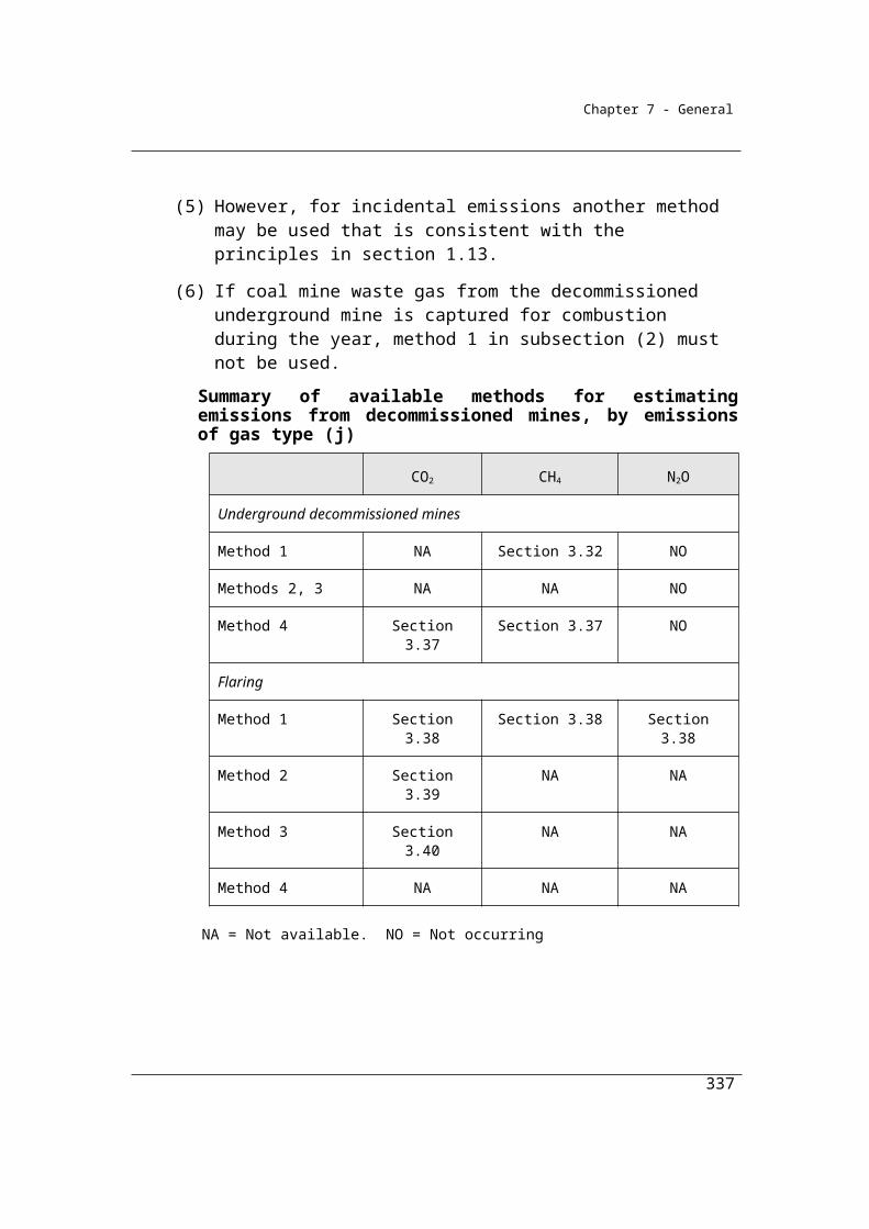
Chapter 7 - General
4.22A Method 1A—product other than cement clinker, lime or soda ash for use of carbonates in clay materials
(1) Method 1A is measure the amount of emissions of carbon dioxide released from each clay material consumed in the industrial process during the reporting year, measured in CO2-e tonnes, using the following formula:
j j jE = Q × ICC × 3.664
where:
Ej is the emissions of carbon dioxide released from the clay material consumed in the industrial process during the reporting year in a State or Territory (j) mentioned in column 2 of an item in the table in subsection (2), measured in CO2-e tonnes.
Qj is the quantity of clay material consumed in the industrial process during the reporting year in a State or Territory (j) mentioned in column 2 of an item in the table in subsection (2), measured in tonnes and estimated under Division 4.2.5.
ICCj is the inorganic carbon content factor of clay material specified in column 3 of an item in the table in subsection (2) for each State or Territory (j) mentioned in column 2 of the item.
(2) For ICCj in subsection (1), column 3 of an item in the following table specifies the inorganic carbon content factor for a State or Territory (j) mentioned in column 2 of the item.
Item State or Territory (j) Inorganic carbon content factor
1 New South Wales 6.068 10-3
2 Victoria 2.333 10-4
3 Queensland 2.509 10-3
4 Western Australia 3.140 10-4
5 South Australia 5.170 10-4
6 Tasmania 1.050 10-3
7 Australian Capital Territory 6.068 10-3
8 Northern Territory 5.170 10-4
337
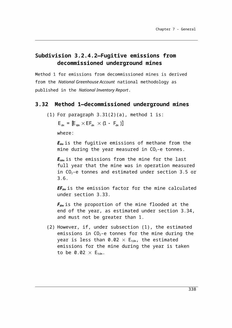
Chapter 7 - General
4.23 Method 3—product other than cement clinker, lime or soda ash
Method 3 is based on the Tier 3 approach in the IPCC Guidelines for National Greenhouse Inventories which utilises information on the purity of the carbonate inputs. This method requires sampling and analysis of the raw materials to determine the material’s pure carbonate content, which is then used in the estimation. This estimation differs from Method 1, which utilises raw carbonate material with specified degrees of impurity as an input into the estimation.
(1) Method 3 is:
Step 1
Measure the amount of emissions of carbon dioxide in CO2-e tonnes released from each pure carbonate consumed in the industrial process during the year as follows:
where:Eij is the emissions of carbon dioxide (j) from a pure carbonate (i) consumed in the industrial process during the year measured in CO2-e tonnes.
EFij is the carbon dioxide (j) emission factor for the pure carbonate (i) in tonnes of emissions of carbon dioxide per tonne of pure carbonate, that is:
(a) for calcium carbonate—0.440;(b) for magnesium carbonate—0.522;(c) for dolomite—0.477;(d) for any other pure carbonate—the factor for the carbonate in
accordance with Chapter 2 of Volume 3 of the 2006 IPCC Guidelines.
Qi is the quantity of the pure carbonate (i) entering the industrial process during the year measured in tonnes and estimated under Division 4.2.5.
338
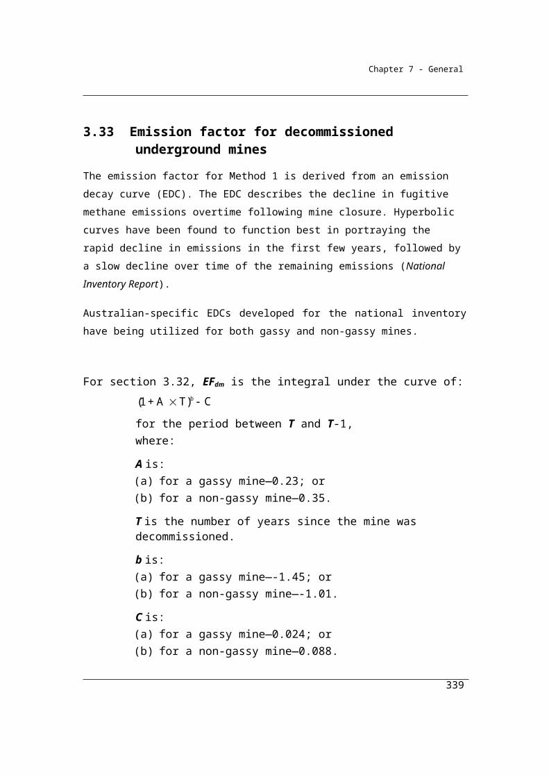
Chapter 7 - General
Fcal is: (a) the fraction of the pure carbonate consumed in the industrial
process during the year; or(b) if the information in paragraph (a) is not available—the value
1.γ is the factor 1.861 × 10⁻³ for converting a quantity of carbon dioxide from cubic metres at standard conditions of pressure and temperature to CO2-e tonnes.RCCSCO2 is carbon dioxide captured for permanent storage measured in cubic metres in accordance with Division 1.2.3.
Step 2
Add together the amount of emissions of carbon dioxide for each pure carbonate consumed in the industrial process during the year.
(2) Method 3 requires each carbonate to be sampled and analysed in accordance with sections 4.24 and 4.25.
4.23A Method 3A—product other than cement clinker, lime or soda ash for use of carbonates in clay materials
Method 3A is:Step 1
Measure the amount of emissions of carbon dioxide released from each clay material consumed in the industrial process during the reporting year, measured in CO2-e tonnes, using the following formula:
where:E is the emissions of carbon dioxide released from the clay material consumed in the industrial process during the reporting year, measured in CO2-e tonnes.Q is the quantity of clay material consumed in the industrial process during the reporting year, measured in tonnes and estimated under Division 4.2.5.ICC is the inorganic carbon content factor of the clay material.
γ is the factor 1.861 10-3 for converting a quantity of carbon dioxide from cubic metres at standard conditions of pressure and temperature to CO2-e tonnes.RCCSCO2is carbon dioxide captured for permanent storage, measured in cubic metres in accordance with Division 1.2.3.
339
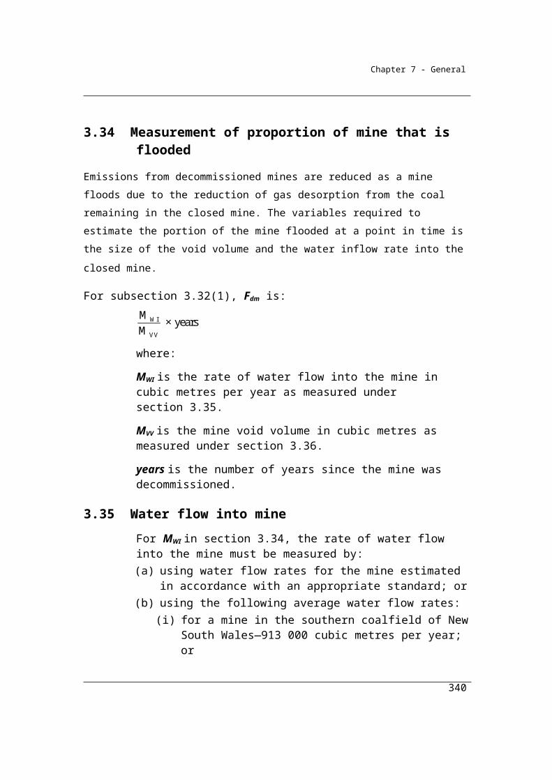
Chapter 7 - General
Step 2
Identify the amount of emissions of carbon dioxide for each clay material consumed in the industrial process during the reporting year.
Step 3
Add together each amount identified under step 2.
4.23B General requirements for sampling clay material
(1) A sample of clay material must:(a) be derived from a composite of amounts of the clay material; and(b) be collected on enough occasions to produce a representative
sample; and(c) be free from bias so that any estimates are neither over nor under
estimates of the true value; and(d) be tested for bias in accordance with an appropriate standard.
(2) The value obtained from the samples of the clay material must be used only for the delivery period or consignment of the clay material for which it was intended to be representative.
4.23C General requirements for analysing clay material
(1) Analysis of samples of the clay material must be performed in accordance with:
(a) industry practice; and(b) the general principles for measuring emissions mentioned in
section 1.13.
(2) The minimum frequency of analysis of samples of clay material must be in accordance with the Tier 3 method in section 2.2.1.1 of Chapter 2 of Volume 3 of the 2006 IPCC Guidelines.
4.24 General requirements for sampling carbonates
(1) A sample of a carbonate must be derived from a composite of amounts of the carbonate consumed.
(2) The samples must be collected on enough occasions to produce a representative sample.
(3) The samples must also be free of bias so that any estimates are neither over nor under estimates of the true value.
(4) Bias must be tested in accordance with an appropriate standard.
340
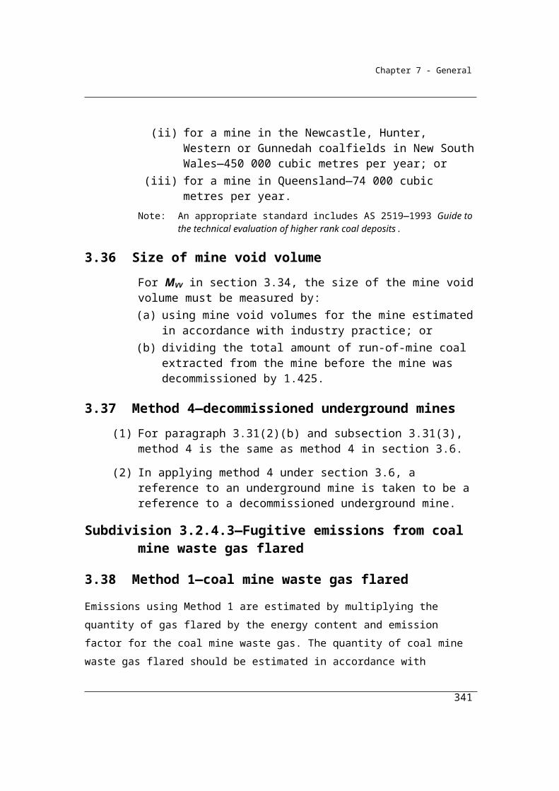
Chapter 7 - General
Note: An example of an appropriate standard is AS 4264.4—1996 – Coal and coke – sampling – Determination of precision and bias.
(5) The value obtained from the samples must only be used for the delivery period or consignment of the carbonate for which it was intended to be representative.
4.25 General requirements for analysis of carbonates
(1) Analysis of samples of carbonates must be in accordance with industry practice and must be consistent with the principles in section 1.13.
(2) The minimum frequency of analysis of samples of carbonates must be in accordance with the Tier 3 method of section 2.2.1.1 of Chapter 2 of Volume 3 of the 2006 IPCC Guidelines.
341
Chapter 7 - General
Division 4.2.4—Soda ash use and productionThis Division addresses emissions from the consumption and also from the production of soda ash. The consumption of soda ash generates carbon dioxide emissions regardless of the industry that consumes the product. Examples of
industries that use soda ash are given in Section 4.26.
4.26 Application
This Division applies to emissions from the use of soda ash and emissions of carbon dioxide from the chemical transformation of calcium carbonate, sodium chloride, ammonia and coke into sodium bicarbonate and soda ash.Examples of uses of soda ash in industrial processes:1 Glass production.2 Soap and detergent production.3 Flue gas desulphurisation.4 Pulp and paper production.
4.27 Outline of Division
Emissions released from the use and production of soda ash must be estimated in accordance with:
(a) for the use of soda ash in production processes—Subdivision 4.2.4.1; or
(b) for the production of soda ash—Subdivision 4.2.4.2.
Subdivision 4.2.4.1—Soda ash use
4.28 Available methods
(1) Subject to section 1.18, one of the following methods must be used for estimating emissions of carbon dioxide released during a year from the operation of a facility constituted by the use of soda ash in a production process:
(a) method 1 under section 4.29;(b) method 4 under Part 1.3.
Note: There is no method 2 or 3 for this Division.
(2) However, for incidental emissions another method may be used that is consistent with the principles in section 1.13.
342
Chapter 7 - General
Summary of available methods, for estimating emissions from soda ash use, by emissions of gas type (j)
CO2 CH4 N2O
Method 1 Section 4.29 NO NO
Methods 2, 3 and 4 NA NO NO
NA = not available. NO = Not occurring
4.29 Method 1—use of soda ash
This Method is derived from the methodology used for the National Greenhouse Accounts. It involves the multiplication of the quantity of soda ash consumed in the production process by the emission factor for soda ash.
Method 1 is:
ij i ijE = Q EFwhere:
Eij is the emissions of carbon dioxide (j) from soda ash (i) consumed in the production process during the year measured in CO2-e tonnes.
Qi is the quantity of soda ash (i) consumed in the production process during the year measured in tonnes and estimated under Division 4.2.5.
EFij is 0.415, which is the carbon dioxide (j) emission factor for soda ash (i) measured in tonnes of carbon dioxide emissions per tonne of soda ash.
Subdivision 4.2.4.2—Soda ash production
Emissions from soda ash production arise from the consumption of fuels for energy and from the calcination of limestone and sodium bicarbonate. The production of soda ash is a multi-step process involving the generation and reabsorption of carbon dioxide. To obtain a more accurate estimation of emissions from the consumption of fuels and calcination processes a carbon balance approach is taken.
343

Chapter 7 - General
4.30 Available methods
(1) Subject to section 1.18, one of the following methods must be used for estimating emissions released during a year from the operation of a facility that is constituted by an activity that produces soda ash:
(a) method 1 under section 4.31;(b) method 2 under section 4.32;(c) method 3 under section 4.33;(d) method 4 under Part 1.3.
(2) However, for incidental emissions another method may be used that is consistent with the principles in section 1.13.
Summary of available methods, for estimating emissions from soda ash production, by emissions of gas type (j)
CO2 CH4 N2O
Method 1 Section 4.31 Section 4.31 Section 4.31
Method 2 Section 4.32 NA NA
Method 3 Section 4.33 NA NA
Method 4 Part 1.3 NA NA
NA = Not available
4.31 Method 1—production of soda ash
Method 1 is:Step 1
Calculate the carbon content in fuel type (i) or carbonate material (j) delivered for the activity during the year measured in tonnes of carbon as follows:
i i i j j j jΣ CCF ×Q + Σ CCF ×F×L
344
Chapter 7 - General
where:
∑i means sum the carbon content values obtained for all fuel types (i).CCFi is the carbon content factor mentioned in Schedule 3 measured in tonnes of carbon for each appropriate unit of fuel type (i) consumed during the year from the operation of the activity.Qi is the quantity of fuel type (i) delivered for the activity during the year measured in an appropriate unit and estimated in accordance with Division 2.2.5, 2.3.6 and 2.4.6.
∑j means sum the carbon content values obtained for all pure carbonate material (j).
CCFj is the carbon content factor mentioned in Schedule 3 measured in tonnes of carbon for each tonne of pure carbonate material (j) consumed during the year from the operation of the activity.Fj is the fraction of pure carbonate material (j) in the raw carbonate input material and taken to be 0.97 for calcium carbonate and 0.018 for magnesium carbonate.L j is the quantity of raw carbonate input material (j) delivered for the activity during the year measured in tonnes and estimated in accordance with Division 4.2.5.
Step 2
Calculate the carbon content in products (p) leaving the activity during the year measured in tonnes of carbon as follows:
p p p pCCF F A
where:
∑p means sum the carbon content values obtained for all product types (p).CCFp is the carbon content factor mentioned in Schedule 3 and measured in tonnes of carbon for each tonne of product type (p) produced during the year.
Fp is the fraction of pure carbonate material in the product type (p).Ap is the quantity of product types (p) produced leaving the activity during the year measured in tonnes.
345

Chapter 7 - General
Step 3
Calculate the carbon content in waste by-product types (r) leaving the activity, other than as an emission of greenhouse gas, during the year, measured in tonnes of carbon, as follows:
r r r rCCF F Y
where:
r means sum the carbon content values obtained for all waste by-product types (r).CCFr is the carbon content factor mentioned in Schedule 3 measured in tonnes of carbon for each tonne of waste by-product types (r).Fr is the fraction of pure carbonate material in the waste by-product types (r).Yr is the quantity of waste by-product types (r) leaving the activity during the year measured in tonnes.
Step 4
Calculate the carbon content in the amount of the change in stocks of inputs, products and waste by-products held within the boundary of the activity during the year in tonnes of carbon as follows:
i i qi j j qj p p ap r r yr CCF S + CCF S + CCF S + CCF S
where:
i has the same meaning as in step 1.CCFi has the same meaning as in step 1.Δsqi is the change in stocks of fuel type (i) for the activity and held within the boundary of the activity during the year measured in tonnes.j has the same meaning as in step 1.CCFj has the same meaning as in step 1.ΔSqj is the change in stocks of pure carbonate material (j) for the activity and held within the boundary of the activity during the year measured in tonnes.p has the same meaning as in step 2.
CCFp has the same meaning as in step 2.
Δsap is the change in stocks of product types (p) produced by the activity and held within the boundary of the activity during the year measured in tonnes.
346

Chapter 7 - General
r has the same meaning as in step 3.CCFr has the same meaning as in step 3.ΔSyr is the change in stocks of waste by-product types (r) produced from the operation of the activity and held within the boundary of the activity during the year measured in tonnes.
Step 5
Calculate the emissions of carbon dioxide released from the operation of the activity during the year measured in CO2-e tonnes as follows:
(a) add the amounts worked out under steps 2, 3 and 4 to work out a new amount (amount A);
(b) subtract amount A from the amount worked out under step 1 to work out a new amount (amount B);
(c) multiply amount B by 3.664 to work out the amount of emissions released from the operation of the activity during a year.
4.32 Method 2—production of soda ash
Method 2 is:
Step 1 Calculate the carbon content in fuel types (i) or carbonate material (j) delivered for the activity during the year measured in tonnes of carbon as follows:
i i i j j jΣ CCF ×Q + Σ CCF ×L
where:∑i means sum the carbon content values obtained for all fuel types (i).
CCFi is the carbon content factor measured in tonnes of carbon for each appropriate unit of fuel type (i) consumed during the year from the operation of the activity.
Qi is the quantity of fuel type (i) delivered for the activity during the year measured in an appropriate unit and estimated in accordance with Divisions 2.2.5, 2.3.6 and 2.4.6.
347

Chapter 7 - General
∑j means sum the carbon content values obtained for all pure carbonate material (j).CCFj is the carbon content factor measured in tonnes of carbon for each pure carbonate material (j) consumed during the year from the operation of the activity.Lj is the quantity of pure carbonate material (j) delivered for the activity during the year measured in tonnes and estimated in accordance with Division 4.2.5.
Step 2 Calculate the carbon content in products (p) leaving the activity during the year measured in tonnes of carbon as follows:
p p pCCF A
where:∑p means sum the carbon content values obtained for all product types (p).CCFp is the carbon content factor measured in tonnes of carbon for each tonne of product type (p) produced during the year.Ap is the quantity of product types (p) produced leaving the activity during the year measured in tonnes.
Step 3 Calculate the carbon content in waste by-product types (r) leaving the activity, other than as an emission of greenhouse gas, during the year, measured in tonnes of carbon, as follows:
r r rCCF Y
where:r means sum the carbon content values obtained for all waste by-product types (r).CCFr is the carbon content factor measured in tonnes of carbon for each tonne of waste by-product types (r).Yr is the quantity of waste by-product types (r) leaving the activity during the year measured in tonnes.
Step 4 Calculate the carbon content in the amount of the change in stocks of inputs, products and waste by-products held within the boundary of the activity during the year in tonnes of carbon as follows:
CO2i i qi j j qj p p ap r r yr CCF S + CCF S + CCF S + CCF S + RCCS
348

13.664
Chapter 7 - General
where:i has the same meaning as in step 1.CCFi has the same meaning as in step 1.Δsqi is the change in stocks of fuel type (i) for the activity and held within the boundary of the activity during the year measured in tonnes.j has the same meaning as in step 1.CCFj has the same meaning as in step 1.ΔSqj is the change in stocks of pure carbonate material (j) for the activity and held within the boundary of the activity during the year measured in tonnes.p has the same meaning as in step 2.CCFp has the same meaning as in step 2.Δsap is the change in stocks of product types (p) produced by the
activity and held within the boundary of the activity during the
year measured in tonnes.
r has the same meaning as in step 3.CCFr has the same meaning as in step 3.Δsyr is the change in stocks of waste by-product types (r) produced from the operation of the activity and held within the boundary of the activity during the year measured in tonnes.α is the factor for converting the mass of carbon dioxide to a mass of carbon.
γ is the factor 1.861 × 10⁻³ for converting a quantity of carbon dioxide from cubic metres at standard conditions of pressure and temperature to CO2-e tonnes.RCCSCO2 is carbon dioxide captured for permanent storage measured in cubic metres in accordance with Division 1.2.3.
Step 5 Calculate the emissions of carbon dioxide released from the operation of the activity during the year measured in CO2-e tonnes as follows:
(a) add the amounts worked out under steps 2, 3 and 4 to work out a new amount (amount A);
(b) subtract amount A from the amount worked out under step 1 to work out a new amount (amount B);
(c) multiply amount B by 3.664 to work out the amount of emissions released from the operation of the activity during a year.
349
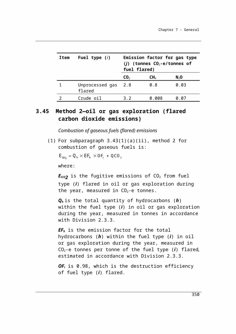
Chapter 7 - General
(2) If a fuel type (i) or carbonate material (j) delivered for the activity during the year accounts for more than 5% of total carbon input for the activity based on a calculation using the factors mentioned in Schedule 3, sampling and analysis of fuel type (i) or carbonate material (j) must be carried out to determine its carbon content.
(3) The sampling and analysis for fuel type (i) is to be carried out using the sampling and analysis provided for in Divisions 2.2.3, 2.3.3 and 2.4.3.
(4) The sampling for carbonate materials (j) is to be carried out in accordance with section 4.24.
(5) The analysis for carbonate materials (j) is to be carried out in accordance with ASTM C25-06, Standard Test Methods for Chemical Analysis of Limestone, Quicklime, and Hydrated Lime or an equivalent standard.
4.33 Method 3—production of soda ash
(1) Subject to subsections (2) and (3), method 3 is the same as method 2.
(2) The sampling and analysis for fuel type (i) is to be carried out using the sampling and analysis provided for in Divisions 2.2.4, 2.3.4 and 2.4.4 or an equivalent sampling and analysis method.
(3) The sampling for carbonate material (j) is to be carried out in accordance with ASTM C50-00 (2006), Standard Practice for Sampling, Sample Preparation, Packaging, and Marking of Lime and Limestone Products.
350

Chapter 7 - General
Division 4.2.5—Measurement of quantity of carbonates consumed and products derived from carbonates
4.34 Purpose of Division
This Division sets out how quantities of carbonates consumed from the operation of the activity and the quantities of products derived from carbonates produced from the operation of the activity are to be estimated for the purpose of working out the emissions released from the consumption and production of carbonates.
Division 4.2.5 specifies the criteria for the estimation of the amounts of carbonate consumed or produced during the operation of a facility during a year.
There are four criteria available for the estimation of the quantities of carbonates reflecting differing levels of measurement effort and precision.
Under the National Greenhouse and Energy Reporting Regulations 2008, the criterion chosen by the Reporter to estimate carbonate inputs and outputs is required to be reported. Measuring equipment calibrated to a measurement requirement mentioned in Sections 4.37 and 4.38 refers to the standards required for measurement to support all commercial transactions covered by the National Measurement Act 1960 and associated instruments.
In Section 4.37 it is intended that measured data for carbonates delivered (at the point of sale) would also meet the Criterion AAA under certain circumstances. These circumstances are that stocks of the carbonate consumed at the facility are less than 5% of carbonate consumption for the facility during the year and that the stock changes by less than 1% during the year. It is intended that the analysis may be conducted by the supplier.
The simplified measurement of consumption criterion is available in those cases where the Reporter does not purchase their carbonates and where the Reporter also does not have metering equipment installed that meets the requirements of criterion AAA. In these cases, it is intended that Reporters should estimate consumption using metering devices or measurement techniques in practice in the industry. Such measurements would need to meet the criteria set out in section 1.13 of
351
Chapter 7 - General
transparency, comparability, accuracy and completeness. Such data would be classified and reported as ‘BBB’ data.
The restriction on the choice of criteria at 4.35 (3) is designed to ensure time series
consistency of the measurements.
(1) This Division applies to the operation of a facility (the activity) that is constituted by:
(a) the production of cement clinker; or(b) the production of lime; or(c) the calcination of carbonates in an industrial process; or(d) the use and production of soda ash.
(2) This Division sets out how the quantities of carbonates consumed from the operation of the activity, and the quantities of products derived from carbonates produced from the operation of the activity, are to be estimated for the following:
(a) Ai and Ackd in section 4.4;(b) Qi and Qtoc in section 4.8;(c) Ai in section 4.13;(d) Qi and Alkd in section 4.17;(e) Qj in sections 4.22, 4.22A, 4.23, 4.29, 4.55, 4.66, 4.71 and 4.94;(f) Q in section 4.23A;(g) Lj in sections 4.31 and 4.32.
4.35 Criteria for measurement
(1) Quantities of carbonates consumed from the operation of the activity, or quantities of products derived from carbonates produced from the operation of the activity, must be estimated in accordance with this section.
Acquisition involves commercial transaction
(2) If the acquisition of the carbonates, or the dispatch of the products derived from carbonates, involves a commercial transaction, the quantity of the carbonates or products must be estimated using one of the following criteria:
(a) the quantity of the carbonates acquired or products dispatched for the facility during the year as evidenced by invoices issued by the vendor of the carbonates or products (criterion A);
(b) as provided in section 4.36 (criterion AA);
352
Chapter 7 - General
(c) as provided in section 4.37 (criterion AAA).
(3) If, during a year, criterion AA, or criterion AAA using paragraph 4.37(2)(a), is used to estimate the quantity of carbonates acquired or products dispatched, then, in each year following that year, only criterion AA, or criterion AAA using paragraph 4.37(2)(a), (respectively) is to be used.
Acquisition does not involve commercial transaction
(4) If the acquisition of the carbonates or the dispatch of the products does not involve a commercial transaction, the quantity the carbonates or products must be estimated using one of the following criteria:
(a) as provided in paragraph 4.37(2)(a) (criterion AAA);(b) as provided in section 4.38 (criterion BBB).
4.36 Indirect measurement at point of consumption or production—criterion AA
(1) For paragraph 4.35(b), criterion AA is the amount of carbonates consumed from the operation of the activity, or the amount of products derived from carbonates produced from the operation of the activity, during the year based on amounts delivered or dispatched during the year:
(a) as evidenced by invoices; and(b) as adjusted for the estimated change in the quantity of the stockpiles
of carbonates or the quantity of the stockpiles of products derived from carbonates during the year.
(2) The volume of carbonates, or products derived from carbonates, in the stockpile for the activity must be measured in accordance with industry practice.
4.37 Direct measurement at point of consumption or production—criterion AAA
(1) For paragraph 4.35(c), criterion AAA is the direct measurement during the year of:
(a) the quantities of carbonates consumed from the operation of the activity; or
(b) the quantities of products derived from carbonates produced from the operation of the activity.
(2) The measurement must be:
353
Chapter 7 - General
(a) carried out using measuring equipment calibrated to a measurement requirement; or
(b) for measurement of the quantities of carbonates consumed from the operation of the activity—carried out at the point of sale using measuring equipment calibrated to a measurement requirement.
(3) Paragraph (2)(b) only applies if:(a) the change in the stockpile of the carbonates for the activity during
the year is less than 1% of total consumption of the carbonates from the operation of the activity on average during the year; and
(b) the stockpile of the carbonates for the activity at the beginning of the year is less than 5% of total consumption of the carbonates from the operation of the activity during the year.
4.38 Acquisition or use or disposal without commercial transaction—criterion BBB
For paragraph 4.35(d), criterion BBB is the estimation of the consumption of carbonates, or the products derived from carbonates, during the year in accordance with industry practice if the equipment used to measure consumption of the carbonates, or the products derived from carbonates, is not calibrated to a measurement requirement.
4.39 Units of measurement
Measurements of carbonates and products derived from carbonates must be converted to units of tonnes.
354
Chapter 7 - General
Part 4.3—Industrial processes—chemical industryThis Part applies to any chemical industry that generates emissions of carbon dioxide through the use of fuels as feedstocks or as carbon reductants, as described below. Nitric acid production is also addressed in this chapter.
It is intended that the quantities of fuels consumed for industrial process purposes are to be estimated in accordance with the same criteria as has been set out for fuels consumption in Chapter 2.
Other sources of emissions arising from the production of the products listed below, such as from the combustion of fuels for energy purposes, are not described in this chapter and must be estimated using the Methods described in other chapters.
Division 4.3.1—Ammonia productionAmmonia production involves the consumption of fossil fuel for both energy and non-energy purposes. CO2 emissions are generated in the primary steam reforming process in which the source of fuel, commonly natural gas, is used to derive hydrogen.
Emissions from the use of natural gas for its energy value should be separated from its non-energy purposes, if possible. Emissions and fuels consumed for energy should be estimated using Methods provided under Chapter 2. Emissions and fuel use as an input into ammonia production should be estimated using Methods provided in this Division. If this separation cannot be completed then, in order to minimise the risk of duplication or omission, all emissions from the use of gas in ammonia production should be included within the industrial processes sector using methods detailed in this Division.
In order to deduct carbon dioxide captured for permanent storage reporters are required to use Method 2 or higher. These higher order methods provide a more accurate estimate of the carbon dioxide emissions than under Method 1, the default method. As the carbon dioxide captured is deducted from the emissions estimate it is necessary to have a greater level of accuracy in the emissions estimate than is achieved using Method 1.
355
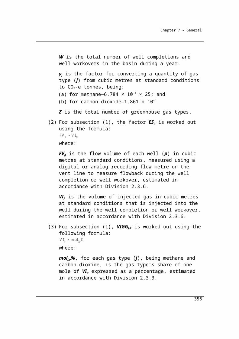
Chapter 7 - General
4.40 Application
This Division applies to chemical industry ammonia production.
4.41 Available methods
(1) Subject to section 1.18, one of the following methods must be used for estimating emissions released during a year from the operation of a facility that is constituted by the production of ammonia:
(a) method 1 under section 4.42;(b) method 2 under section 4.43;(c) method 3 under section 4.44;(d) method 4 under Part 1.3.
(2) However, for incidental emissions another method may be used that is consistent with the principles in section 1.13.
Summary of available methods, for estimating emissions from ammonia production, by emissions of gas type (j)
NO = Not
occurring.
4.42 Method 1—ammonia production
Method 1 for emissions of carbon dioxide released from the use of fuels as feedstocks in the production of ammonia is derived from the methodology used for the National Greenhouse Accounts.
(1) Method 1 is:
i i ij ij
Q × EC × EFE = R 1000
356
CO2 CH4 N2O
Method 1 Section 4.42 NO NO
Method 2 Section 4.43 NO NO
Method 3 Section 4.44 NO NO
Method 4 Method 4 under Part 1.3.
NO NO
Chapter 7 - General
where:
Eij is the emissions of carbon dioxide released from the production of ammonia during the year measured in CO2-e tonnes.
Qi is the quantity of each type of feedstock or type of fuel (i) consumed from the production of ammonia during the year, measured in the appropriate unit and estimated using a criterion in Division 2.3.6.
ECi is the energy content factor for fuel type (i) used as a feedstock in the production of ammonia during the year, estimated under section 6.5.
EFij is the carbon dioxide emission factor for each type of feedstock or type of fuel (i) used in the production of ammonia during the year, including the effects of oxidation, measured in kilograms for each gigajoule according to source as mentioned in Part 2 of Schedule 1.
R is the quantity of carbon dioxide measured in tonnes derived from the production of ammonia during the year, captured and transferred for use in the operation of another facility, estimated using an applicable criterion in Division 2.3.6 and in accordance with any other requirements of that Division.
(2) For the purposes of calculating R in subsection (1), if:(a) more than one fuel is consumed in the production of ammonia; and(b) the carbon dioxide generated from the production of ammonia is
captured and transferred for use in the operation of another facility or captured for permanent storage;
the total amount of carbon dioxide that may be deducted in relation to the production of ammonia is to be attributed to each fuel consumed in proportion to the carbon content of the fuel relative to the total carbon content of all fuel consumed in the production of ammonia.
4.43 Method 2—ammonia production
(1) Method 2 is:
2
i i ijij co
Q EC EFE - R - RCCS
1 000
where:
Eij is the emissions of carbon dioxide released from the production of ammonia during the year measured in CO2-e tonnes.
357

Chapter 7 - General
Qi is the quantity of each type of feedstock or type of fuel (i) consumed from the production of ammonia during the year, measured in the appropriate unit and estimated using an applicable criterion in Division 2.3.6.
ECi is the energy content factor for fuel type (i) used as a feedstock in the production of ammonia during the year, estimated under section 6.5.
EFij is the carbon dioxide emission factor for each type of feedstock or type of fuel (i) used in the production of ammonia during the year, including the effects of oxidation, measured in kilograms for each gigajoule according to source in accordance with subsection (2).
R is the quantity of carbon dioxide measured in tonnes derived from the production of ammonia during the year, captured and transferred for use in the operation of another facility, estimated using an applicable criterion in Division 2.3.6 and in accordance with any other requirements of that Division.
γ is the factor 1.861 × 10⁻³ for converting a quantity of carbon dioxide from cubic metres at standard conditions of pressure and temperature to CO2-e tonnes.
RCCSCO2 is carbon dioxide captured for permanent storage measured in cubic metres in accordance with Division 1.2.3.
(2) The method for estimating emission factors for gaseous fuels in Division 2.3.3 applies for working out the factor EFij.
(3) For the purposes of calculating R in subsection (1), if:(a) more than one fuel is consumed in the production of ammonia; and(b) the carbon dioxide generated from the production of ammonia is
captured and transferred for use in the operation of another facility or captured for permanent storage;
the total amount of carbon dioxide that may be deducted in relation to the production of ammonia is to be attributed to each fuel consumed in proportion to the carbon content of the fuel relative to the total carbon content of all fuel consumed in the production of ammonia.
4.44 Method 3—ammonia production
(1) Method 3 is the same as method 2 under section 4.43.
358

Chapter 7 - General
(2) In applying method 2 as method 3, the method for estimating emission factors for gaseous fuels in Division 2.3.4 applies for working out the factor EFij.
359
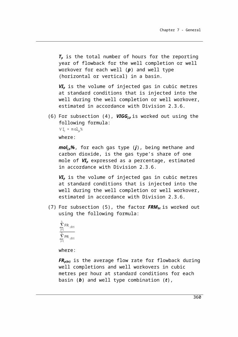
Chapter 7 - General
Division 4.3.2—Nitric acid productionThe manufacture of nitric acid (HNO3) generates nitrous oxide (N2O) as a by-product of the high temperature catalytic oxidation of ammonia (NH3).
4.45 Application
This Division applies to chemical industry nitric acid production.
4.46 Available methods
Method 1, 2 or 4 are available for plants, unless abatement measures are in place –
in which case Method 2 or 4 must be used.
(1) Subject to section 1.18 and this section, one of the following methods must be used for estimating emissions during a year from the operation of a facility that is constituted by the production of nitric acid at a plant:
(a) method 1 under section 4.47;(b) method 2 under section 4.48;(c) method 4 under Part 1.3.
Note: There is no method 3 for this Division.
(2) However, for incidental emissions another method may be used that is consistent with the principles in section 1.13.
(3) Method 1 must not be used if the plant has used measures to reduce nitrous oxide emissions.
360
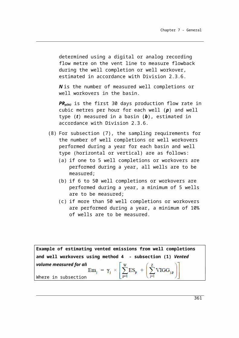
Chapter 7 - General
Summary of available methods, for estimating emissions from nitric acid production, by emissions of gas type (j)
CO2 CH4 N2O
Method 1 NO NO Section 4.47
Method 2 NO NO Section 4.48
Method 3 NO NO NA
Method 4 NO NO Method 4 under Part 1.3
NO = Not occurring, NA = Not available.
4.47 Method 1—nitric acid production
Method 1 for emissions released from the production of nitric acid (is derived from the methodology used for the National Greenhouse Accounts, with the emission factors for individual plants taken from the IPCC Guidelines for National Greenhouse Inventories Volume 3, Part 1.
(1) Method 1 is:
ijk ijk ikE = EF A where:
Eijk is the emissions of nitrous oxide released during the year from the production of nitric acid at plant type (k) measured in CO2-e tonnes.
EFijk is the emission factor of nitrous oxide for each tonne of nitric acid produced during the year from plant type (k).
Aik is the quantity, measured in tonnes, of nitric acid produced during the year from plant type (k).
(2) For EFijk in subsection (1), column 3 of an item in the following table specifies the emission factor of nitrous oxide for each tonne of nitric acid produced from a plant type (k) specified in column 2 of that item.
361
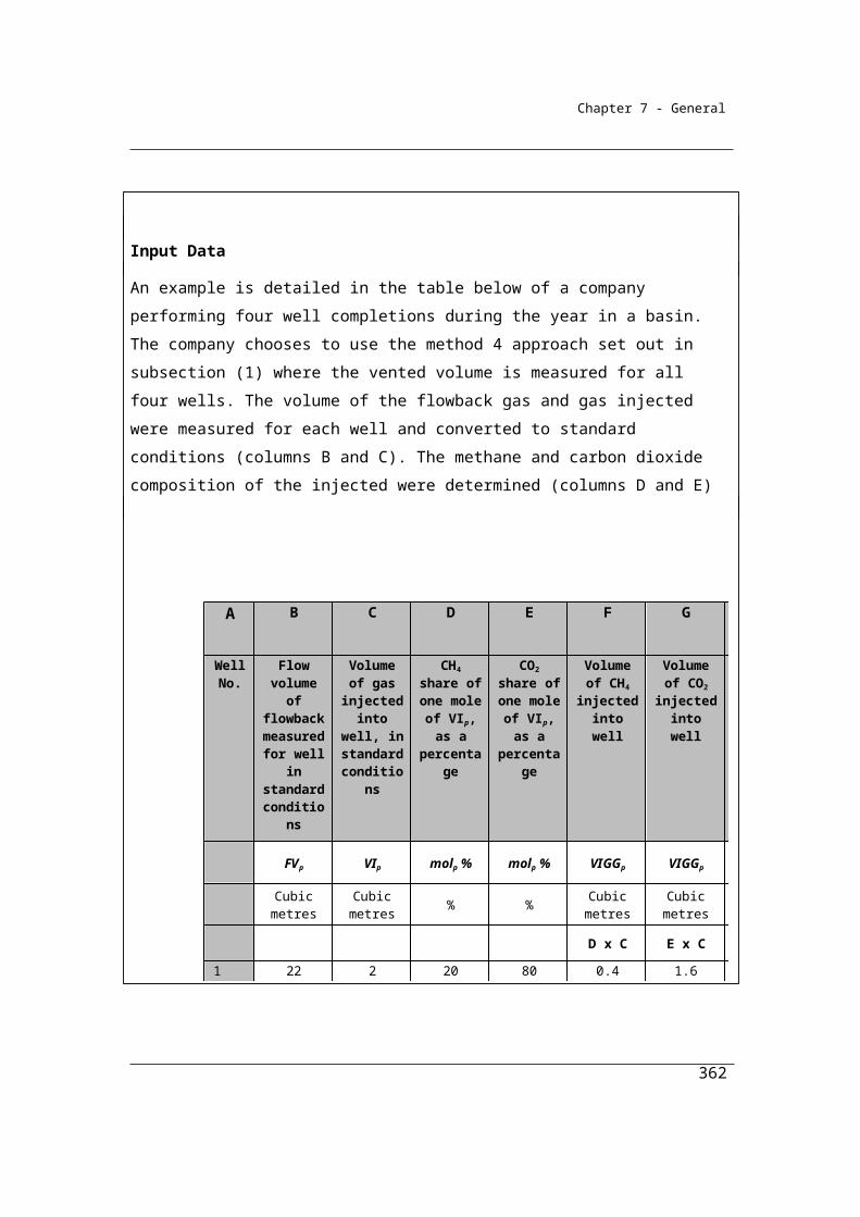
Chapter 7 - General
Item Plant type (k) Emission factor of nitrous oxide(tonnes CO2-e per tonne of nitric acid production)
1 Atmospheric pressure plants 1.492 Medium pressure combustion plant 2.093 High pressure plant 2.68
Note: The emission factors specified in this table apply only to method 1 and the operation of a facility that is constituted by a plant that has not used measures to reduce nitrous oxide emissions.
Example: A high pressure nitric acid plant produces 45,000 tonnes of nitric acid during the year. The Reporter elects to use Method 1 (Division 4.3.2) for each of greenhouse emission gases (j) (nitrous oxide) to calculate the Industrial Process emissions. Emissions are estimated as follows:
where:Eijk is the emissions of nitrous oxide released during the year from the production of nitric acid at the plant type (k) measured in CO2 e tonnes.
EFijk is the emission factor of nitrous oxide for each tonne of nitric acid produced during the year from plant type (k). In this case the emission factor is 2.68 tonnes CO2-e per tonne of nitric acid production for a high pressure plant.
Aik is the quantity, measured in tonnes, of nitric acid produced during the year from plant type (k). In this case production is 45,000 tonnes.
Therefore, to estimate emissions of nitrous oxide in CO2-e tonnes:
=45,000 x 2.68
Total emissions of nitrous oxide = 120,600 t CO2-e
4.48 Method 2—nitric acid production
For Method 2, facility-specific emission factors may be derived from periodic emissions monitoring undertaken in accordance with the provisions of Chapter 1 (and, in particular, section 1.28). These facility-specific emission factors should be substituted into the equation specified in 4.47 (1) to estimate emissions.
362
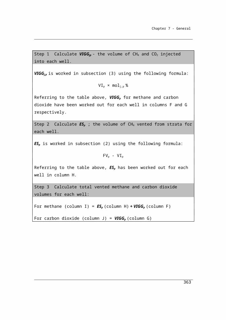
Chapter 7 - General
(1) Subject to this section, method 2 is the same as method 1 under section 4.47.
(2) In applying method 1 under section 4.47, to work out the factor EFijk:(a) periodic emissions monitoring must be used and conducted in
accordance with Part 1.3; and(b) the emission factor must be measured as nitrous oxide in CO2-e
tonnes for each tonne of nitric acid produced during the year from the plant.
(3) For method 2, all data on nitrous oxide concentrations, volumetric flow rates and nitric acid production for each sampling period must be used to estimate the flow-weighted average emission rate of nitrous oxide for each unit of nitric acid produced from the plant.
363
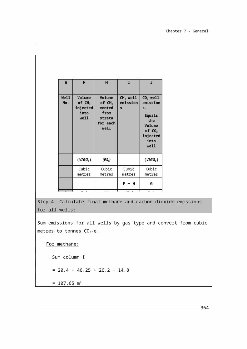
Chapter 7 - General
Division 4.3.3—Adipic acid productionMethod 1 for emissions released from the production of adipic acid is described in IPCC 2006 Guidelines for National Greenhouse Gas Inventories Volume 3, Part 1. Currently, there is no adipic acid production recorded in Australia.
4.49 Application
This Division applies to chemical industry adipic acid production.
4.50 Available methods
(1) Subject to section 1.18, one of the methods for measuring emissions released in the production of adipic acid set out in section 3.4 of the 2006 IPCC Guidelines must be used for estimating emissions during a year from the operation of a facility that is constituted by the production of adipic acid.
(2) For incidental emissions another method may be used that is consistent with the principles in section 1.13.
364
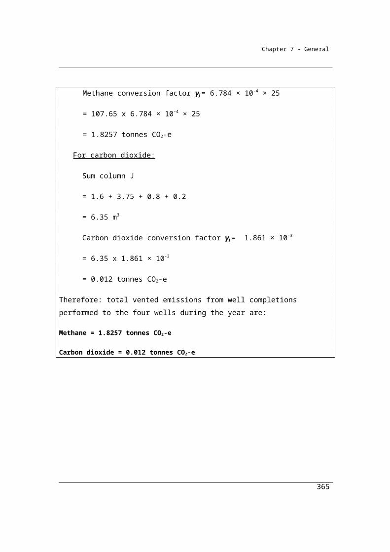
Chapter 7 - General
Division 4.3.4—Carbide productionMethod 1 for emissions released from the production of carbide is described in IPCC 2006 Guidelines for National Greenhouse Gas Inventories Volume 3, Part 1. Currently, there is no carbide production recorded in Australia.
4.51 Application
This Division applies to chemical industry carbide production.
4.52 Available methods
(1) Subject to section 1.18, one of the methods for measuring emissions from carbide production set out in section 3.6 of the 2006 IPCC Guidelines must be used for estimating emissions during a year from the operation of a facility that is constituted by carbide production.
(2) For incidental emissions another method may be used that is consistent with the principles in section 1.13.
365

Chapter 7 - General
Division 4.3.5—Chemical or mineral production, other than carbide production, using a carbon reductant or carbon anode
Emissions of carbon dioxide released from the use of fuels as carbon reductants or carbon anodes in the production of chemical or mineral products (other than carbide) should be estimated using methods provided in this Division. The use of fuels for energy purposes should be estimated using methods in Chapter 2 and reported separately.
Some of the industries included in this Division are listed below.
In order to deduct carbon dioxide captured for permanent storage reporters are required to use Method 2 or higher. These higher order methods provide a more accurate estimate of the carbon dioxide emissions than under Method 1, the default method. As the carbon dioxide captured is deducted from the emissions estimate it is necessary to have a greater level of accuracy in the emissions estimate than is achieved using Method 1.
4.53 Application
This Division applies to emissions of carbon dioxide from activities producing a chemical or mineral product (other than carbide production), using a carbon reductant or carbon anode, including the following products:
(a) fused alumina;(b) fused magnesia;(c) fused zirconia;(d) glass;(e) synthetic rutile;(f) titanium dioxide.
Note: Magnesia produced in a process that does not use an electric arc furnace must be reported under Division 4.2.3.
4.54 Available methods
(1) Subject to section 1.18, one of the following methods must be used for estimating emissions released during a year from the operation of a
366
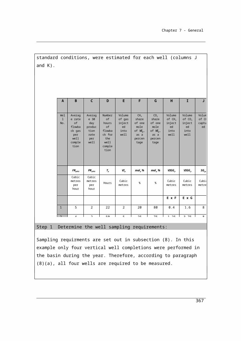
Chapter 7 - General
facility that is constituted by the production of a chemical or mineral product:
(a) method 1 under section 4.55;(b) method 2 under section 4.56;(c) method 3 under section 4.57;(d) method 4 under Part 1.3.
(2) However, for incidental emissions another method may be used that is consistent with the principles in section 1.13.
Summary of available methods, for estimating emissions from titanium dioxide production, by emissions of gas type (j)
CO2 CH4 N2O
Method 1 Section 4.55 NO NO
Method 2 Section 4.56 NO NO
Method 3 Section 4.57 NO NO
Method 4 Part 1.3 NO NO
NO = Not occurring.
4.55 Method 1—chemical or mineral production, other than carbide production, using a carbon reductant or carbon anode
Method 1 for emissions of carbon dioxide released from the use of fuels as carbon reductants or carbon anodes in the production of a chemical or mineral product is derived from the methodology used for the National Greenhouse Accounts.
Method 1 is:Step 1 Work out the carbon content in fuel types (i) or carbonaceous input
material delivered for the activity during the year, measured in tonnes of carbon, as follows:
i ii Q CCF
where:i means the sum of the carbon content values obtained for all fuel types (i) or carbonaceous input material.
367

Chapter 7 - General
CCFi is the carbon content factor mentioned in Schedule 3, measured in tonnes of carbon, for each appropriate unit of fuel type (i) or carbonaceous input material consumed during the year from the operation of the activity.Qi is the quantity of fuel type (i) or carbonaceous input material delivered for the activity during the year, measured in an appropriate unit and estimated in accordance with criterion A in Divisions 2.2.5, 2.3.6, 2.4.6 and 4.2.5.
Step 2 Work out the carbon content in products (p) leaving the activity during the year, measured in tonnes of carbon, as follows:
p p p CCF A
where:p means the sum of the carbon content values obtained for all product types (p).CCFp is the carbon content factor, measured in tonnes of carbon, for each tonne of product type (p) produced during the year.Ap is the quantity of product types (p) produced leaving the activity during the year, measured in tonnes.
Step 3 Work out the carbon content in waste by-product types (r) leaving the activity, other than as an emission of greenhouse gas, during the year, measured in tonnes of carbon, as follows:
r r r CCF Y
where:r means the sum of the carbon content values obtained for all waste by-product types (r).CCFr is the carbon content factor, measured in tonnes of carbon, for each tonne of waste by-product types (r).Yr is the quantity of waste by-product types (r) leaving the activity during the year, measured in tonnes.
Step 4 Work out the carbon content in the amount of the change in stocks of inputs, products and waste by-products held within the boundary of the activity during the year, measured in tonnes of carbon, as follows:
i i qi p p ap r r yr CCF S + CCF S + CCF S
368
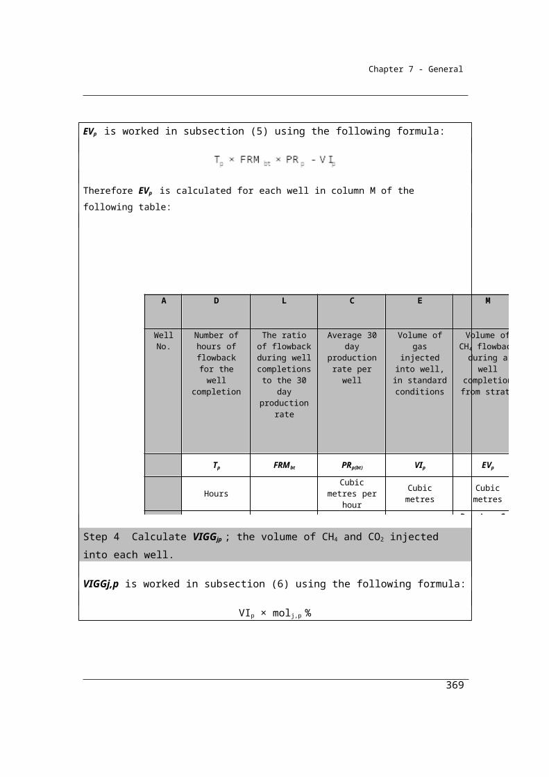
Chapter 7 - General
where:i has the same meaning as in step 1.CCFi has the same meaning as in step 1.ΔSqi is the change in stocks of fuel type (i) for the activity and held within the boundary of the activity during the year, measured in tonnes.p has the same meaning as in step 2.CCFp has the same meaning as in step 2.ΔSap is the change in stocks of product types (p) produced by the activity and held within the boundary of the activity during the year, measured in tonnes.r has the same meaning as in step 3.CCFr has the same meaning as in step 3.ΔSyr is the change in stocks of waste by-product types (r) produced from the operation of the activity and held within the boundary of the activity during the year, measured in tonnes.
Step 5 Work out the emissions of carbon dioxide released from the operation of the activity during the year, measured in CO2-e tonnes, as follows:
(a) add the amounts worked out under steps 2, 3 and 4 to work out a new amount (amount A);
(b) subtract amount A from the amount worked out under step 1 to work out a new amount (amount B);
(c) multiply amount B by 3.664 to work out the amount of emissions released from the operation of the activity during the year.
4.56 Method 2—chemical or mineral production, other than carbide production, using a carbon reductant or carbon anode
(1) Subject to this section, method 2 is the same as method 1 under section 4.55.
(2) In applying method 1 as method 2, step 4 in section 4.55 is to be omitted and the following step 4 substituted.
Step 4 Work out the carbon content in the amount of the change in stocks of inputs, products and waste by-products held within the boundary of the activity during the year, measured in tonnes of carbon, as follows:
2i i qi p p ap r r yr co CCF S + CCF S + CCF S + γRCCS
369
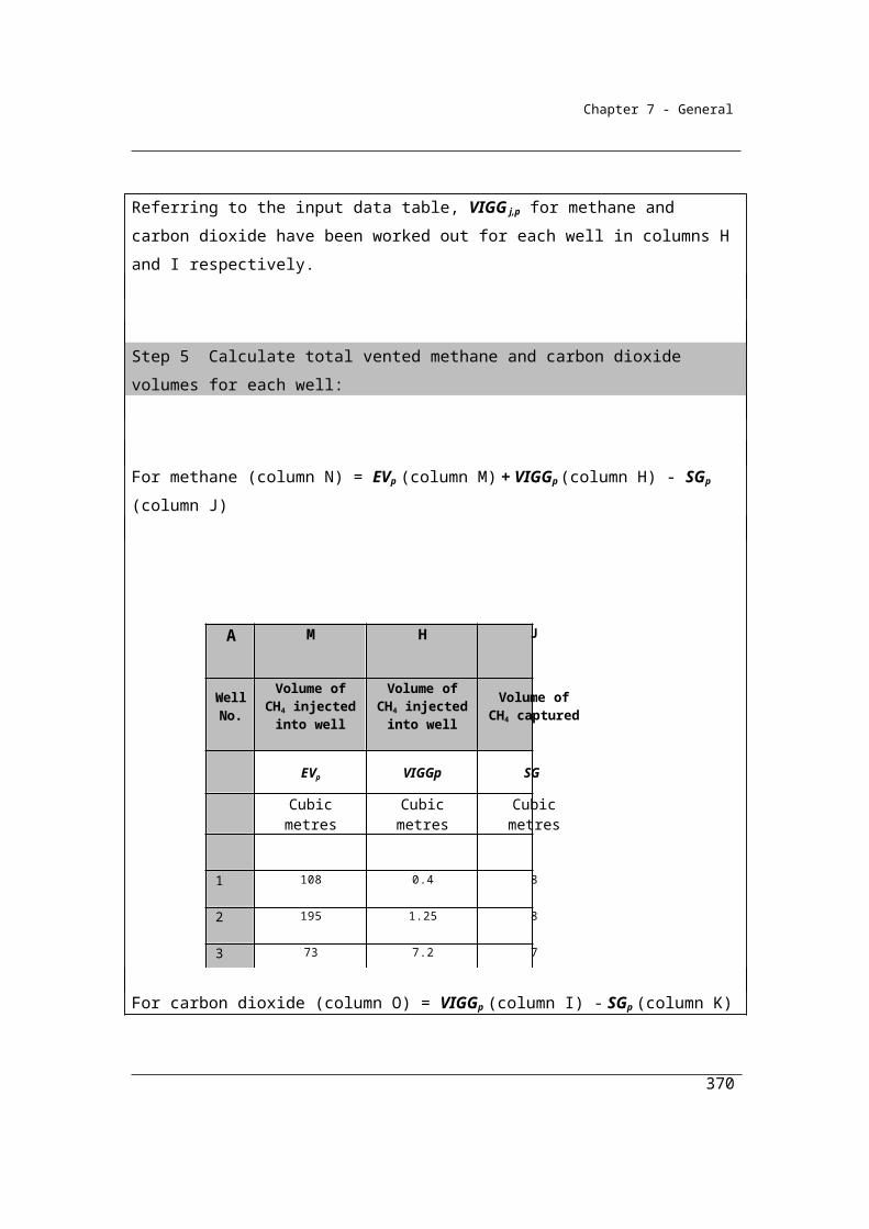
13.664
Chapter 7 - General
where:i has the same meaning as in step 1.CCFi has the same meaning as in step 1.ΔSqi is the change in stocks of fuel type (i) for the activity and held within the boundary of the activity during the year, measured in tonnes.p has the same meaning as in step 2.CCFp has the same meaning as in step 2.
ΔSap is the change in stocks of product types (p) produced by the activity and held within the boundary of the activity during the year, measured in tonnes.r has the same meaning as in step 3.CCFr has the same meaning as in step 3.
ΔSyr is the change in stocks of waste by-product types (r) produced from the operation of the activity and held within the boundary of the activity during the year, measured in tonnes.α is the factor for converting the mass of carbon dioxide to a mass of carbon.γ is the factor 1.861 × 10⁻³ for converting a quantity of carbon dioxide from cubic metres at standard conditions of pressure and temperature to CO2-e tonnes.RCCSCO2 is carbon dioxide captured for permanent storage, measured in cubic metres in accordance with Division 1.2.3.
(3) If a fuel type (i) or carbonaceous input material delivered for the activity during the year accounts for more than 5% of total carbon input for the activity, based on a calculation using the factors specified in Schedule 3, sampling and analysis of fuel type (i) or carbonaceous input material must be carried out to determine its carbon content.
(4) The sampling and analysis is to be carried out using the sampling and analysis provided for in Divisions 2.2.3, 2.3.3 and 2.4.3 that apply to the combustion of solid, gaseous and liquid fuels.
4.57 Method 3—chemical or mineral production, other than carbide production, using a carbon reductant or carbon anode
(1) Subject to this section, method 3 is the same as method 2 under section 4.56.
370
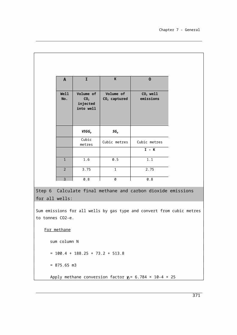
Chapter 7 - General
(2) If a fuel type (i) or carbonaceous input material delivered for the activity during the year accounts for more than 5% of total carbon input for the activity, based on a calculation using the factors specified in Schedule 3, sampling and analysis of fuel type (i) or carbonaceous input material must be carried out to determine its carbon content.
(3) The sampling and analysis is to be carried out using the methods set out in Divisions 2.2.4, 2.3.4 and 2.4.4 that apply to the combustion of solid, gaseous and liquid fuels.
371
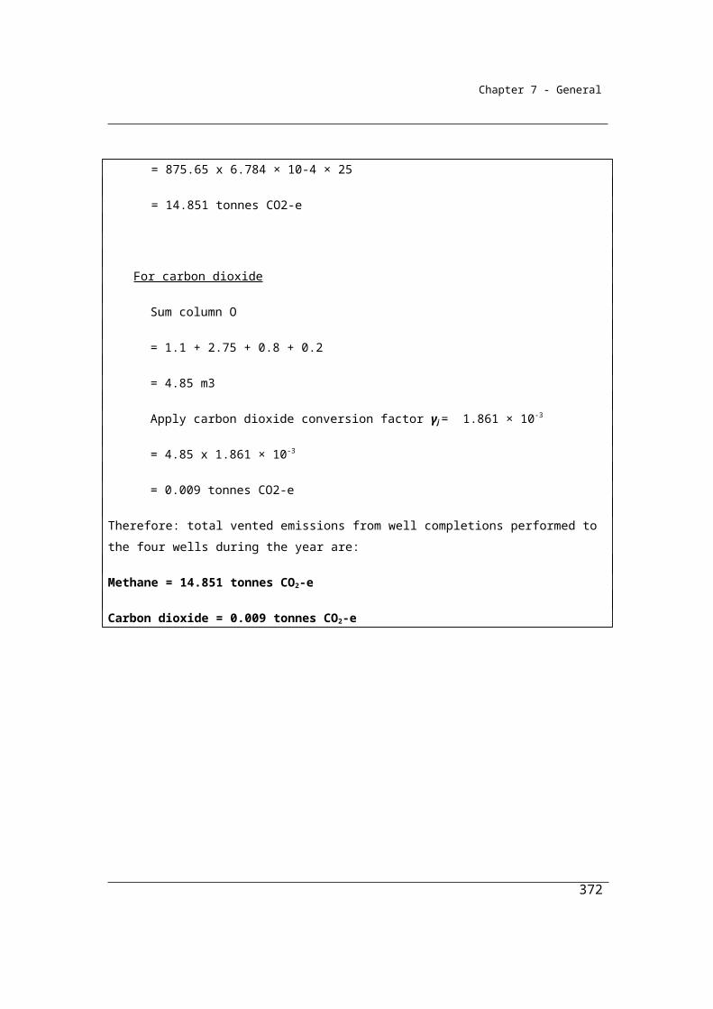
Chapter 7 - General
Division 4.3.6—Sodium cyanide production
4.58 Application
This Division applies to emissions of carbon dioxide or nitrous oxide from activities producing sodium cyanide.
4.59 Available methods
(1) Subject to section 1.18, one of the following methods must be used for estimating emissions released during a reporting year from the operation of a facility that is constituted by the production of sodium cyanide:
(a) method 1 under section 4.55;(b) method 2 under section 4.56;(c) method 3 under section 4.57;(d) method 4 under Part 1.3.
(2) For estimating incidental emissions released during a reporting year from the operation of a facility that is constituted by the production of sodium cyanide, another method may be used that is consistent with the principles mentioned in section 1.13.
372
Chapter 7 - General
Part 4.4—Industrial processes—metal industryThis Part applies to any metal industry that generates emissions of carbon dioxide through the use of fuels as carbon reductants, as described below. Perfluorocarbon emissions from aluminium production are also addressed in this part.
The quantities of fuels consumed for industrial process purposes should be estimated in accordance with the same criteria as has been set out for fuels consumption in Chapter 2.
Other sources of emissions arising from the production of the products listed below, such as from the combustion of fuels for energy, are not described in this chapter and must be estimated using the Methods described in other chapters.
Division 4.4.1—Iron, steel or other metal production using an integrated metalworks
This division applies to any facility that produces iron, steel or any metals produced using an integrated metalworks. Metals such as iron, steel, lead and silicon may be produced in an integrated metalworks where the metal and coke is produced on the same site. In this case it is difficult to identify emissions attributable to each part of the production process. In this case, emissions are estimated from the activity as a whole by estimating the inputs and outputs. The methods for estimating emissions of carbon dioxide are based on a carbon balance approach reducing the complexity of the calculation for these facilities.
Steel, in particular, is also produced using an electric arc furnace (EAF) or similar process. While not considered an integrated metalworks, emissions from iron or steel production using an EAF are to be estimated and reported within Division 4.4.1.
In order to deduct carbon dioxide captured for permanent storage reporters are required to use Method 2 or higher. These higher order methods provide a more accurate estimate of the carbon dioxide emissions than under Method 1, the default method. As the carbon dioxide captured is deducted from the emissions estimate it is necessary to have a greater level of accuracy in the emissions estimate than is achieved using Method 1.
373

Chapter 7 - General
Note that emissions from limestone and dolomite use in Iron and Steel production are to be reported under Division 4.2.3 ‘Use of carbonates for the production of a product other than cement clinker, lime or soda ash’.
4.63 Application
This Division applies to emissions from production of the following:(a) iron;(b) steel;(c) any metals produced using integrated metalworks.
4.64 Purpose of Division
(1) This Division applies to determining emissions released during a year from the operation of a facility that is constituted by an activity that produces a metal, for example, an integrated metalworks.
(2) An integrated metalworks means a metalworks that produces coke and a metal (for example, iron or steel).
(3) The emissions from the activity are to be worked out as a total of emissions released from the production of a metal and from all other emissions released from the operation of the activity (including the production of coke if the activity is an integrated metalworks).
(4) However, the amount of emissions to be determined for this source is only the amount of emissions from the use of coke as a carbon reductant in the metal production estimated in accordance with section 2.69.Note: The amount of emissions to be determined for other activities is as provided
for in other provisions of this Determination.
4.65 Available methods for production of a metal from an integrated metalworks
(1) Subject to section 1.18, one of the following methods must be used for estimating emissions released from the activity during a year:
(a) method 1 under section 4.66;(b) method 2 under section 4.67;(c) method 3 under section 4.68;(d) method 4 under Part 1.3.
(2) However, for incidental emissions another method may be used that is consistent with the principles in section 1.13.
374
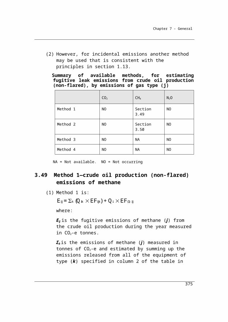
Chapter 7 - General
Summary of available methods, for estimating emissions from iron and steel production, by emissions of gas type (j)
CO2 CH4 N2O
Method 1 Section 4.66 NO NO
Method 2 Section 4.67 NO NO
Method 3 Section 4.68 NO NO
Method 4 Method 4 under Part 1.3
NO NO
NA = Not available. NO = Not occurring.
4.66 Method 1—production of a metal from an integrated metalworks
Method 1 sets out the estimation of emissions from a facility producing both a metal and coke. It specifies that emissions should be estimated using a carbon mass balance approach for the facility as a whole. Method 1 utilises carbon content factors listed in Appendix A (Schedule 3 in the Determination). These carbon content factors are derived directly from the carbon dioxide emission factors listed in Chapter 2. There are no carbon content factors specified for products or for waste by-products. It is intended that these should be estimated by industry based on the principles of Section 1.13, namely transparency, comparability, accuracy and completeness.
The carbon mass balance approach requires fuels to be estimated based on quantities of fuels delivered rather than consumed. Criteria AA or AAA cannot be utilised as changes in stocks of fuels are explicitly taken into account in the mass balance estimation directly.
375
Chapter 7 - General
Method 1, based on a carbon mass balance approach, is:Step 1 Calculate the carbon content in fuel types (i) or carbonaceous input
material delivered for the activity during the year measured in tonnes of carbon as follows:
i i i CCF Q
where:i means sum the carbon content values obtained for all fuel types (i) or carbonaceous input material.CCFi is the carbon content factor mentioned in Schedule 3 measured in tonnes of carbon for each appropriate unit of fuel type (i) or carbonaceous input material consumed during the year from the operation of the activity.Qi is the quantity of fuel type (i) or carbonaceous input material delivered for the activity during the year measured in an appropriate unit and estimated in accordance with criterion A in Division 2.2.5, 2.3.6, 2.4.6 and 4.2.5.
Step 2 Calculate the carbon content in products (p) leaving the activity during the year measured in tonnes of carbon as follows:
p p p CCF A
where:p means sum the carbon content values obtained for all product types (p).CCFp is the carbon content factor measured in tonnes of carbon for each tonne of product type (p) produced during the year.Ap is the quantity of product types (p) produced leaving the activity during the year measured in tonnes.
Step 3 Calculate the carbon content in waste by-product types (r) leaving the activity, other than as an emission of greenhouse gas, during the year, measured in tonnes of carbon, as follows:
r r r CCF Y
376
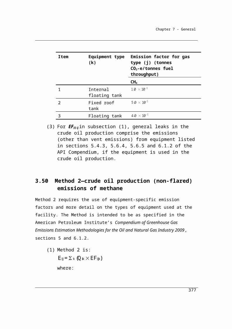
Chapter 7 - General
where:r means sum the carbon content values obtained for all waste by-product types (r).CCFr is the carbon content factor measured in tonnes of carbon for each tonne of waste by-product types (r).Yr is the quantity of waste by-product types (r) leaving the activity during the year measured in tonnes.
Step 4 Calculate the carbon content in the amount of the change in stocks of inputs, products and waste by-products held within the boundary of the activity during the year in tonnes of carbon as follows:
i i qi p p ap r r yr CCF S + CCF S + CCF S
where:i has the same meaning as in step 1.CCFi has the same meaning as in step 1.ΔSqi is the change in stocks of fuel type (i) for the activity and held within the boundary of the activity during the year measured in tonnes.p has the same meaning as in step 2.CCFp has the same meaning as in step 2.ΔSap is the change in stocks of product types (p) produced by the activity and held within the boundary of the activity during the year measured in tonnes.r has the same meaning as in step 3.CCFr has the same meaning as in step 3.ΔSyr is the change in stocks of waste by-product types (r) produced from the operation of the activity and held within the boundary of the activity during the year measured in tonnes.
Step 5 Calculate the emissions of carbon dioxide released from the operation of the activity during the year measured in CO2-e tonnes as follows:
(a) add the amounts worked out under steps 2, 3 and 4 to work out a new amount (amount A);
(b) subtract amount A from the amount worked out under step 1 to work out a new amount (amount B);
(c) multiply amount B by 3.664 to work out the amount of emissions released from the operation of the activity during a year.
377
13.664
Chapter 7 - General
4.67 Method 2—production of a metal from an integrated metalworks
(1) Subject to this section, method 2 is the same as method 1 under section 4.66.
(1A) In applying method 1 as method 2, step 4 in section 4.66 is to be omitted and the following step 4 substituted.
Step 4 Calculate the carbon content in the amount of the change in stocks of inputs, products and waste by-products held within the boundary of the activity during the year in tonnes of carbon as follows:
2i i qi p p ap r r yr co CCF S + CCF S + CCF S + γRCCS
where:i has the same meaning as in step 1.CCFi has the same meaning as in step 1.ΔSqi is the change in stocks of fuel type (i) for the activity and held within the boundary of the activity during the year measured in tonnes.p has the same meaning as in step 2.CCFp has the same meaning as in step 2.ΔSap is the change in stocks of product types (p) produced by the activity and held within the boundary of the activity during the year measured in tonnes.r has the same meaning as in step 3.CCFr has the same meaning as in step 3.ΔSyr is the change in stocks of waste by-product types (r) produced from the operation of the activity and held within the boundary of the activity during the year measured in tonnes.α is the factor for converting the mass of carbon dioxide to a mass of carbon.γ is the factor 1.861 × 10⁻³ for converting a quantity of carbon dioxide from cubic metres at standard conditions of pressure and temperature to CO2-e tonnes.RCCSCO2 is carbon dioxide captured for permanent storage measured in cubic metres in accordance with Division 1.2.3.
(2) If a fuel type (i) or carbonaceous input material delivered for the activity during the year accounts for more than 5% of total carbon input for the activity based on a calculation using the factors specified in Schedule 3,
378
Chapter 7 - General
sampling and analysis of fuel type (i) or carbonaceous input material must be carried out to determine its carbon content.
(3) The sampling and analysis is to be carried out using the sampling and analysis provided for in Divisions 2.2.3, 2.3.3 and 2.4.3 that apply to the combustion of solid, liquid or gaseous fuels.
4.68 Method 3—production of a metal from an integrated metalworks
(1) Subject to this section, method 3 is the same as method 2 under section 4.67.
(2) If a fuel type (i) or carbonaceous input material delivered for the activity during the year accounts for more than 5% of total carbon input for the activity based on a calculation using the factors specified in Schedule 3, sampling and analysis of fuel type (i) or carbonaceous input material must be carried out to determine its carbon content.
(3) The sampling and analysis is to be carried out using the methods set out in Divisions 2.2.4, 2.3.4 and 2.4.4 that apply to the combustion of solid, liquid or gaseous fuels:
Estimating emissions from iron and steel production
Iron and Steel production can involve integrated processes such as coke making and
steel furnace operations within a facility. The complex carbon and energy flows
within the integrated facility can make the estimation of total emissions difficult to
estimate when a bottom-up approach is taken. The carbon mass balance provides a
top-down approach that simplifies the emission estimation process in this case,
allowing the emissions to be estimated as a whole, while taking into account the
carbon input and outputs to the facility as well as stockpile changes.
An emission estimation example using the method 1 carbon balance approach is
provided below. The example is of an integrated iron and steel facility that uses coke
oven coke, coking coal and fuel oil to produce coke, iron and then steel. The facility
also produces coal tar and waste containing carbon, in addition to experiencing fuel
379
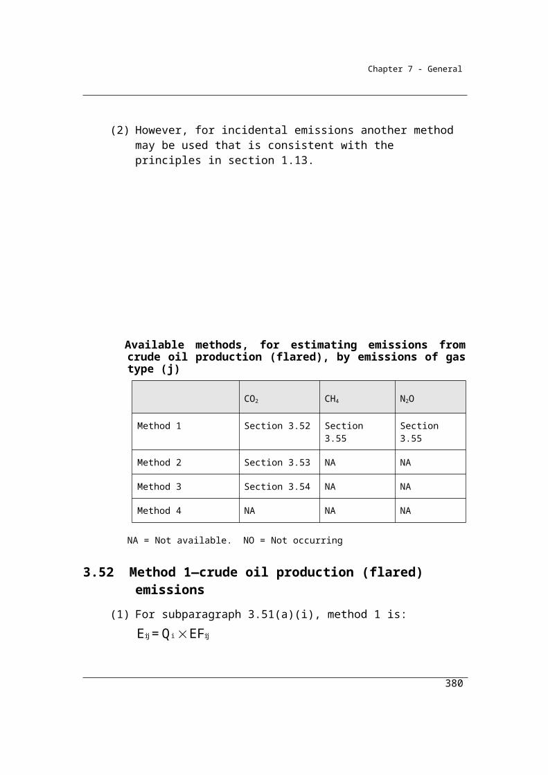
Chapter 7 - General
stock changes during the year. The relevant data for the integrated iron and steel
facility is outlined in the table below.
Data inputs for integrated iron and steel carbon balance example.
Fuel or product type
Fuels delivered during the year
Products produced and
leaving the activity during
the year
Change (increase) in stocks during
the year
Carboncontentfactor
(CCF)
Coke oven coke
60,000 tonnes -5,000 tonnes 0.789
Coking coal 750,000 tonnes 3,000 tonnes 0.752
Fuel oil 3,000 kilolitres 0.797
Coal tar 15,000 tonnes 200 tonnes 0.837
Step 1 Calculate the carbon content in fuel types (i) or carbonaceous input material
delivered for the activity during the year measured in tonnes of carbon as follows:
Where:
CCFi is the carbon content factor mentioned in Appendix A measured in tonnes of
carbon for each appropriate unit of fuel type (i) or carbonaceous input material
consumed during the year from the operation of the activity.
380

Chapter 7 - General
The Method 1 default carbon content factors can be found in Schedule 3 of the NGER
(Measurement) Determination and are shown in the table above.
Qi is the quantity of fuel type (i) or carbonaceous input material delivered for the
activity during the year measured in an appropriate unit and estimated in accordance
with criterion A in Division 2.2.5, 2.3.6 and 2.4.6. In this case the quantities of input
materials are shown in the table above.
To calculate the carbon content for the input materials:
Carbon content of coking coal = (750,000 x 0.752) = 564,000 tonnes of carbon
Carbon content of fuel oil = (3,000 x 0.797) = 2,391 tonnes of carbon
Therefore, total carbon = (564,000 + 2,391) = 566,391 tonnes
Step 2 Calculate the carbon content in products (p) leaving the activity during the
year measured in tonnes of carbon as follows:
Where:
CCFp is the carbon content factor measured in tonnes of carbon for each tonne of
product type (p) produced during the year. In this case the carbon content factor of
each product type is shown in the table above:
Ap is the quantity of product types (p) produced leaving the activity during the year
measured in tonnes. In this case the quantity of product are shown in the table above:
381
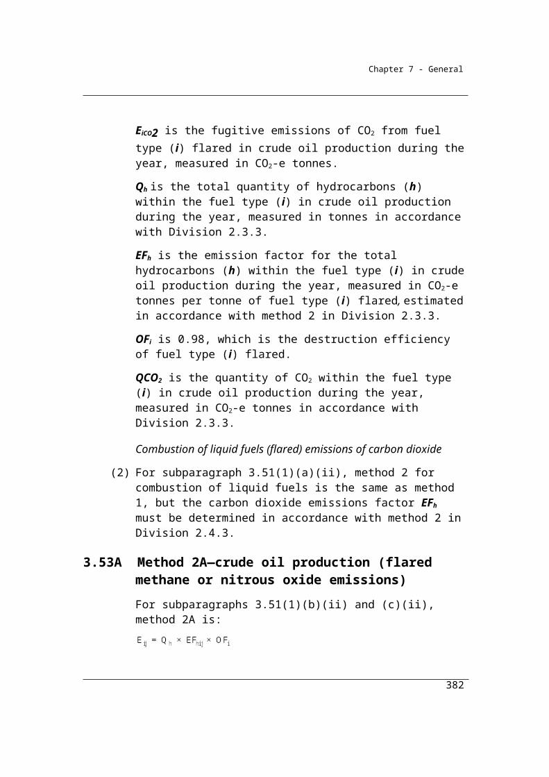
Chapter 7 - General
To calculate the carbon content for the products leaving the activity during the
year:
Carbon Content of crude steel= (920,000 x 0.0017) = 1,564 tonnes of carbon
Carbon Content of coke oven coke = (60,000 x 0.789) = 47,340 tonnes of carbon
Carbon Content of coal tar = (15,000 x 0.837) = 12,555 tonnes of carbon
Therefore, total carbon = (1,564 + 47,340 + 12,555) = 61,459 tonnes
Step 3 Calculate the carbon content in waste by product types (r) leaving the activity,
other than as an emission of greenhouse gas, during the year, measured in tonnes of
carbon, as follows:
Where:
CCFr is the carbon content factor measured in tonnes of carbon for each tonne of
waste by product types (r).
Yr is the quantity of waste by product types (r) leaving the activity during the year
measured in tonnes. In this case the quantities of waste by-products are;
slag, of which 230,000 tonnes was produced. The facility estimated the carbon
content of the slag was 0.0005 tonnes per tonne of slag.
Other non oxidised carbon sources estimated in accordance with the NGER
(Measurement) Determination as being 1500 tonnes.
To calculate the carbon content for the waste products leaving the activity
during the year:
382
Chapter 7 - General
Carbon Content of slag = (230,000 x 0.0005) = 115 tonnes of carbon
Carbon Content of other non oxidised carbon = 1500 tonnes of carbon
Therefore, total carbon = (115 + 1,500) = 1,615 tonnes
Step 4 Calculate the carbon content in the amount of the increase in stocks of inputs,
products and waste by products held within the boundary of the activity during the
year in tonnes of carbon as follows:
Where:
CCFi has the same meaning as in step 1.
ΔSqi is the increase in stocks of fuel type (i) for the activity and held within the
boundary of the activity during the year measured in tonnes. In this case the quantities
of increases in stocks are shown in the table above:
To calculate the carbon content for increase of fuel types
Carbon content of coke oven coke = (-5000 x 0.789) = -3945 tonnes of carbon
Carbon content of coking coal = (3000 x 0.752) = 2256 tonnes of carbon
Therefore, total carbon = (-3945 + 2256) = -1689 tonnes
CCFp has the same meaning as in step 2.
383

Chapter 7 - General
ΔSap is the increase in stocks of product types (p) produced by the activity and held
within the boundary of the activity during the year measured in tonnes. In this case the
quantities of product types shown in the table above:
To calculate the carbon content for increase in stock of product type:
Carbon content of coal tar = (200 x 0.837) = 167.4 tonnes of carbon
Carbon content of crude steel = (1000 x 0.0017) = 1.7 tonnes of carbon
Therefore, total carbon = (167.4 + 1.7) = 169.1 tonnes
CCFr has the same meaning as in step 3.
ΔSyr is the increase in stocks of waste by product types (r) produced from the
operation of the activity and held within the boundary of the activity during the year
measured in tonnes.
There was no change in waste product stock produced and held during the year.
To calculate the total carbon contained in the change of stock:
Carbon content of increase in fuel types = -1689 tonnes
Carbon content of increase in product types = 169.1 tonnes
Carbon content of increase in waste by-products = 0 tonnes
Therefore, total carbon = (-1689 + 169.1 + 0) = -1519.9 tonnes
Step 5 Calculate the emissions of carbon dioxide released from the operation of the
activity during the year measured in CO2 e tonnes as follows:
384
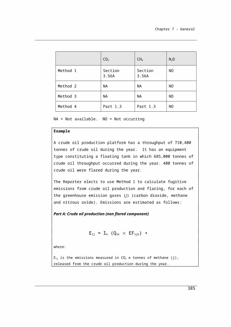
Chapter 7 - General
(a) add the amounts worked out under steps 2, 3 and 4 to work out a new
amount (amount A);
In this case A is:
= 61,459 + 1,615 + -1,519.9
= 61,554.1 tonnes of carbon
(b) subtract amount A from the amount worked out under step 1 to work
out a new amount (amount B);
In this case:
= 566,391 61,554.1
= 504,836.9 tonnes of carbon
(c) multiply amount B by 3.664 to work out the amount of emissions
released from the operation of the activity during a year.
= 504,836.9 x 3.664
= 1,849,722.4016 tonnes CO2-e
Therefore, total carbon balance CO2 emissions from the source = 1,849,722
tonnes
385
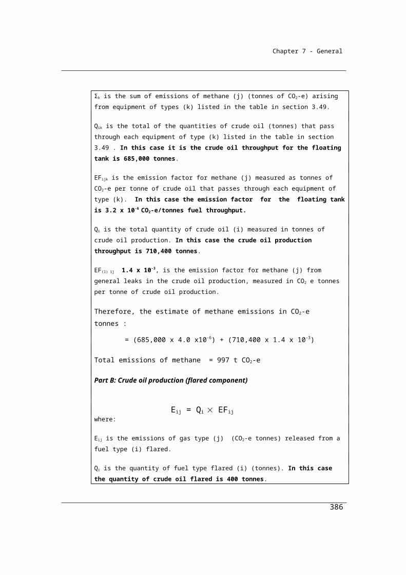
Chapter 7 - General
Division 4.4.2—Ferroalloys productionEmissions of CO2 occur during ferroalloy production as a result of the use of carbon reductants such as coke and the oxidation of a fossil fuel electrode.
4.69 Application
(1) This Division applies to emissions of carbon dioxide from any of the following:
(a) the consumption of a fossil fuel reductant during the production of:(i) a ferroalloy; or
(ii) silicomanganese; or(iii) silicon;
(b) the oxidation of a fossil fuel electrode in the production of:(i) a ferroalloy; or
(ii) silicomanganese; or(iii) silicon.
(2) In this section:
ferroalloy means an alloy of 1 or more elements with iron including, but not limited to, any of the following:
(a) ferrochrome;(b) ferromanganese;(c) ferromolybdenum;(d) ferronickel;(e) ferrosilicon;(f) ferrotitanium;(g) ferrotungsten;(h) ferrovanadium.
4.70 Available methods
(1) Subject to section 1.18, one of the following methods must be used for estimating emissions of carbon dioxide during a year from the operation of a facility that is constituted by the production of ferroalloy metal, silicomanganese or silicon:
(a) method 1 under section 4.71;(b) method 2 under section 4.72;(c) method 3 under section 4.73;
386
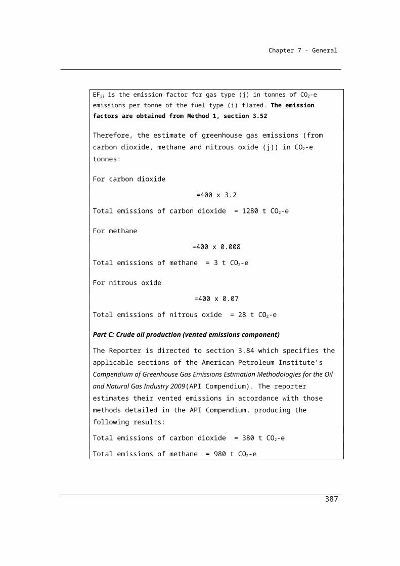
Chapter 7 - General
(d) method 4 under Part 1.3.
(2) However, for incidental emissions another method may be used that is consistent with the principles in section 1.13.
Methane and nitrous oxide emissions arising from the combustion of reductants should be estimated using methods described in Chapter 2 – Fuel Combustion.
Summary of available methods, for estimating emissions from ferroalloy metal production, by emissions of gas type (j)
CO2 CH4 N2O
Method 1 Section 4.71 NO NO
Method 2 Section 4.72 NO NO
Method 3 Section 4.73 NO NO
Method 4 Method 4 under Part 1.3
NO NO
NO = Not occurring.
4.71 Method 1—ferroalloy metal
Method 1, based on a carbon mass balance approach, is:Step 1 Work out the carbon content in fuel types (i) or carbonaceous input
material delivered for the activity during the year, measured in tonnes of carbon, as follows:
i i i CCF Q
where:i means the sum of the carbon content values obtained for all fuel types (i) or carbonaceous input material.CCFi is the carbon content factor mentioned in Schedule 3, measured in tonnes of carbon, for each appropriate unit of fuel type (i) or carbonaceous input material consumed during the year from the operation of the activity.
387
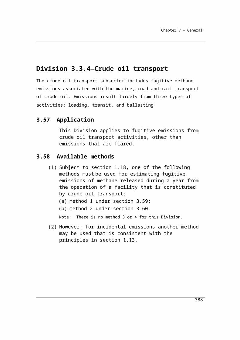
Chapter 7 - General
Qi is the quantity of fuel type (i) or carbonaceous input material delivered for the activity during the year, measured in an appropriate unit and estimated in accordance with:
(a) criterion A in Divisions 2.2.5, 2.3.6 and 2.4.6; or (b) if the quantity of fuel or carbonaceous input material is not
acquired as part of a commercial transaction — industry practice, consistent with the principles in section 1.13.
Step 2 Work out the carbon content in products (p) leaving the activity during the year, measured in tonnes of carbon, as follows:
p p p CCF A
where:p means the sum of the carbon content values obtained for all product types (p).CCFp is the carbon content factor, measured in tonnes of carbon, for each tonne of product type (p) produced during the year.
Ap is the quantity of product types (p) produced leaving the activity during the year, measured in tonnes.
Step 3 Work out the carbon content in waste by-product types (r) leaving the activity, other than as an emission of greenhouse gas, during the year, measured in tonnes of carbon, as follows:
r r r CCF Y
where:r means the sum of the carbon content values obtained for all waste by-product types (r).CCFr is the carbon content factor, measured in tonnes of carbon, for each tonne of waste by-product types (r).Yr is the quantity of waste by-product types (r) leaving the activity during the year, measured in tonnes.
Step 4 Work out the carbon content in the amount of the change in stocks of inputs, products and waste by-products held within the boundary of the activity during the year, measured in tonnes of carbon, as follows:
i i qi p p ap r r yr CCF S + CCF S + CCF S
388

Chapter 7 - General
where:i has the same meaning as in step 1.CCFi has the same meaning as in step 1.ΔSqi is the change in stocks of fuel type (i) for the activity and held within the boundary of the activity during the year, measured in tonnes.p has the same meaning as in step 2.CCFp has the same meaning as in step 2.
ΔSap is the change in stocks of product types (p) produced by the activity and held within the boundary of the activity during the year, measured in tonnes.r has the same meaning as in step 3.CCFr has the same meaning as in step 3.
ΔSyr is the change in stocks of waste by-product types (r) produced from the operation of the activity and held within the boundary of the activity during the year, measured in tonnes.
Step 5 Work out the emissions of carbon dioxide released from the operation of the activity during the year, measured in CO2-e tonnes, as follows:
(a) add the amounts worked out under steps 2, 3 and 4 to work out a new amount (amount A);
(b) subtract amount A from the amount worked out under step 1 to work out a new amount (amount B);
(c) multiply amount B by 3.664 to work out the amount of emissions released from the operation of the activity during the year.
4.72 Method 2—ferroalloy metal
(1) Subject to this section, method 2 is the same as method 1 under section 4.71.
(2) In applying method 1 as method 2, step 4 in section 4.71 is to be omitted and the following step 4 substituted.
Step 4 Work out the carbon content in the amount of the change in stocks of inputs, products and waste by-products held within the boundary of the activity during the year, measured in tonnes of carbon, as follows:
2i p p ap r r yr coi qi CCF S + CCF S + CCF S + γRCCS
389

13.664
Chapter 7 - General
where:i has the same meaning as in step 1.CCFi has the same meaning as in step 1.ΔSqi is the change in stocks of fuel type (i) for the activity and held within the boundary of the activity during the year, measured in tonnes.p has the same meaning as in step 2.CCFp has the same meaning as in step 2.ΔSap is the change in stocks of product types (p) produced by the activity and held within the boundary of the activity during the year, measured in tonnes.r has the same meaning as in step 3.CCFr has the same meaning as in step 3.
ΔSyr is the change in stocks of waste by-product types (r) produced from the operation of the activity and held within the boundary of the activity during the year, measured in tonnes.α is the factor for converting the mass of carbon dioxide to a mass of carbon.γ is the factor 1.861 × 10⁻³ for converting a quantity of carbon dioxide from cubic metres at standard conditions of pressure and temperature to CO2-e tonnes.RCCSCO2 is carbon dioxide captured for permanent storage, measured in cubic metres in accordance with Division 1.2.3.
(3) If a fuel type (i) or carbonaceous input material delivered for the activity during the year accounts for more than 5% of total carbon input for the activity, based on a calculation using the factors specified in Schedule 3, sampling and analysis of fuel type (i) or carbonaceous input material must be carried out to determine its carbon content.
(4) The sampling and analysis is to be carried out using the sampling and analysis provided for in Divisions 2.2.3, 2.3.3 and 2.4.3 that apply to the combustion of solid, gaseous and liquid fuels.
4.73 Method 3—ferroalloy metal
(1) Subject to this section, method 3 is the same as method 2 under section 4.72.
(2) If a fuel type (i) or carbonaceous input material delivered for the activity during the year accounts for more than 5% of total carbon input for the activity, based on a calculation using the factors specified in Schedule 3,
390
Chapter 7 - General
sampling and analysis of fuel type (i) or carbonaceous input material must be carried out to determine its carbon content.
(3) The sampling and analysis is to be carried out using the methods set out in Divisions 2.2.4, 2.3.4 and 2.4.4 that apply to the combustion of solid, gaseous and liquid fuels.
391
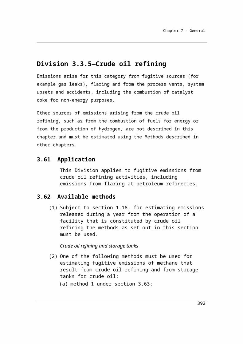
Chapter 7 - General
Division 4.4.3—Aluminium production (carbon dioxide emissions)
4.74 Application
This Division applies to aluminium production.
Sudivision 4.4.3.1—Aluminium—emissions from consumption of carbon anodes in aluminium production
Method 1 for carbon dioxide emissions from aluminium production is intended to reproduce the method set out in the 2006 IPCC Guidelines for National Greenhouse Gas Inventories, which is drawn from the International Aluminium Institute Greenhouse Gas Protocol. As for fuels combusted for energy, Methods 2 and 3 for the category provide for sampling and analysis of fuels in accordance with Chapter 2 to determine facility-specific carbon content factors to be applied in estimating
emissions.
4.75 Available methods
(1) Subject to section 1.18, for estimating emissions of carbon dioxide released during a year from the operation of a facility that is constituted by the production of aluminium involving the consumption of carbon anodes, one of the following methods must be used:
(a) method 1 under section 4.76;(b) method 2 under section 4.77;(c) method 3 under section 4.78;(d) method 4 under Part 1.3.
(2) However, for incidental emissions another method may be used that is consistent with the principles in section 1.13.
392
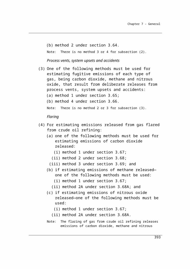
Chapter 7 - General
Available methods, for estimating emissions from aluminium involving the consumption of baked carbon anodes, by emissions of gas type (j)
CO2 CH4 N2O
Method 1 Section 4.76 NO NO
Method 2 Section 4.77 NO NO
Method 3 Section 4.78 NO NO
Method 4 Method 4 under Part 1.3
NO NO
NA = Not available. NO = Not occurring.
4.76 Method 1—aluminium (carbon anode consumption)
Method 1 is:
ij i ijE =A EFwhere:
Eij is the emissions of carbon dioxide released from aluminium smelting and production involving the consumption of carbon anodes during the year measured in CO2-e tonnes.
Ai is the amount of primary aluminium produced in tonnes during the year.
EFij is the carbon dioxide emission factor for carbon anode consumption, measured in CO2-e tonnes for each tonne of aluminium produced during the year, estimated in accordance with the following formula:
a aij
100 S AshEF = NAC 3.664100
where:
NAC is the amount of carbon consumed from a carbon anode consumed in the production of aluminium during the year, worked out at the rate of 0.413 tonnes of carbon anode consumed for each tonne of aluminium produced.
393

Chapter 7 - General
Sa is the mass of sulphur content in carbon anodes that is consumed in the production of aluminium during the year, expressed as a percentage of the mass of the carbon anodes, and is taken to be 2.
Asha is the mass of ash content in carbon anodes that is consumed in the production of aluminium during the year, expressed as a percentage of the mass of the carbon anodes, and is taken to be 0.4.
4.77 Method 2—aluminium (carbon anode consumption)
(1) Subject to this section, method 2 is the same as method 1 under section 4.76.
(2) In applying method 1 under section 4.76, the method for sampling and analysing the fuel type (i) for the factors NAC, Sa and Asha must be determined by sampling and analysing the fuel type for sulphur and ash content, as the case may be, in accordance with:
(a) for solid fuels—method 2 in Division 2.2.3; and(b) for gaseous fuels—method 2 in Division 2.3.3; and(c) for liquid fuels—method 2 in Division 2.4.3.
(3) However, in applying method 1 under section 4.76, the factor Sa may be the amount for the factor as mentioned in section 4.76.
(4) If the amount for the factor Sa as mentioned in section 4.76 is not used, then Sa must be determined by sampling and analysing the fuel type (i) for sulphur content in accordance with subsection (2).
4.78 Method 3—aluminium (carbon anode consumption)
(1) Subject to this section, method 3 is the same as method 1 under section 4.76.
(2) In applying method 1 under section 4.76, the method for sampling and analysing fuel type (i) for the factors NAC, Sa and Asha must be determined by sampling and analysing the fuel type for sulphur and ash content, as the case may be, in accordance with:
(a) for solid fuels—method 3 in Division 2.2.4; and(b) for gaseous fuels—method 3 in Division 2.3.4; and(c) for liquid fuels—method 3 in Division 2.4.4.
394
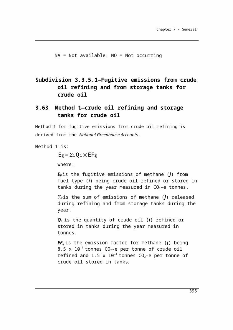
Chapter 7 - General
Subdivision 4.4.3.2—Aluminium—emissions from production of baked carbon anodes in aluminium production
4.79 Available methods
(1) Subject to section 1.18, for estimating emissions of carbon dioxide released during a year from the operation of a facility that is constituted by the production of aluminium involving the production of baked carbon anodes, one of the following methods must be used:
(a) method 1 under section 4.80;(b) method 2 under section 4.81;(c) method 3 under section 4.82;(d) method 4 under Part 1.3.
(2) However, for incidental emissions another method may be used that is consistent with the principles in section 1.13.
Available methods, for estimating emissions from aluminium involving the production of baked carbon anodes, by emissions of gas type (j)
CO2 CH4 N2O
Method 1 Section 4.80 NO NO
Method 2 Section 4.81 NO NO
Method 3 Section 4.82 NO NO
Method 4 Method 4 under Part 1.3
NO NO
NO = Not occurring.
4.80 Method 1—aluminium (baked carbon anode production)
Method 1 is:
i i iij
100 S AshQE = GA Hw BA WT 3.664 + BA 3.664
BA 100
where:
Eij is the emissions of carbon dioxide released from baked carbon anode production for the facility during the year.
395
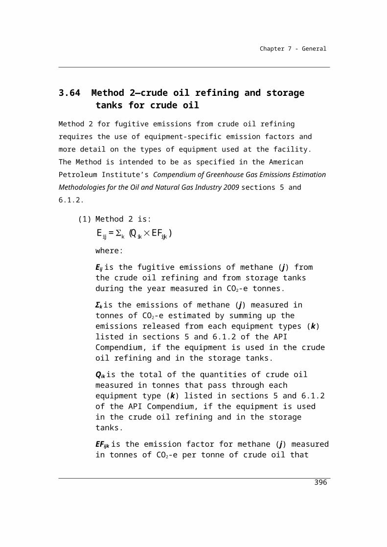
Chapter 7 - General
GA is the initial weight of green anodes used in the production process of the baked carbon anode.
Hw is the weight of the hydrogen content in green anodes used in the production of the baked carbon anode during the year measured in tonnes.
BA is the amount of baked carbon anode produced during the year measured in tonnes.
WT is the amount, in tonnes, of waste tar collected in the production of baked carbon anodes during the year.
ΣQi is the quantity of fuel type (i), measured in the appropriate unit, consumed in the production of baked carbon anodes during the year and estimated in accordance with the requirements set out in the following Divisions:
(a) if fuel type (i) is a solid fuel—Division 2.2.5;(b) if fuel type (i) is a gaseous fuel—Division 2.3.6;(c) if fuel type (i) is a liquid fuel—Division 2.4.6.
Si is the mass of sulphur content in baked carbon anodes that is consumed in the production of aluminium during the year, expressed as a percentage of the mass of the baked carbon anodes, and is taken to be 2.
Ashi is the mass of ash content in baked carbon anodes that is consumed in the production of aluminium during the year, expressed as a percentage of the mass of the baked carbon anodes, and is taken to be 0.4. Note: The default value for Hw is 0.5% of GA.
4.81 Method 2—aluminium (baked carbon anode production)
(1) Subject to this section, method 2 is the same as method 1 under section 4.80.
(2) In applying method 1 under section 4.80, the method for sampling and analysing fuel type (i) for the factors Si and Ashi must be determined by sampling and analysing the fuel type for sulphur and ash content, as the case may be, in accordance with:
(a) for solid fuels—method 2 in Division 2.2.3; and(b) for gaseous fuels—method 2 in Division 2.3.3; and(c) for liquid fuels—method 2 in Division 2.4.3.
396
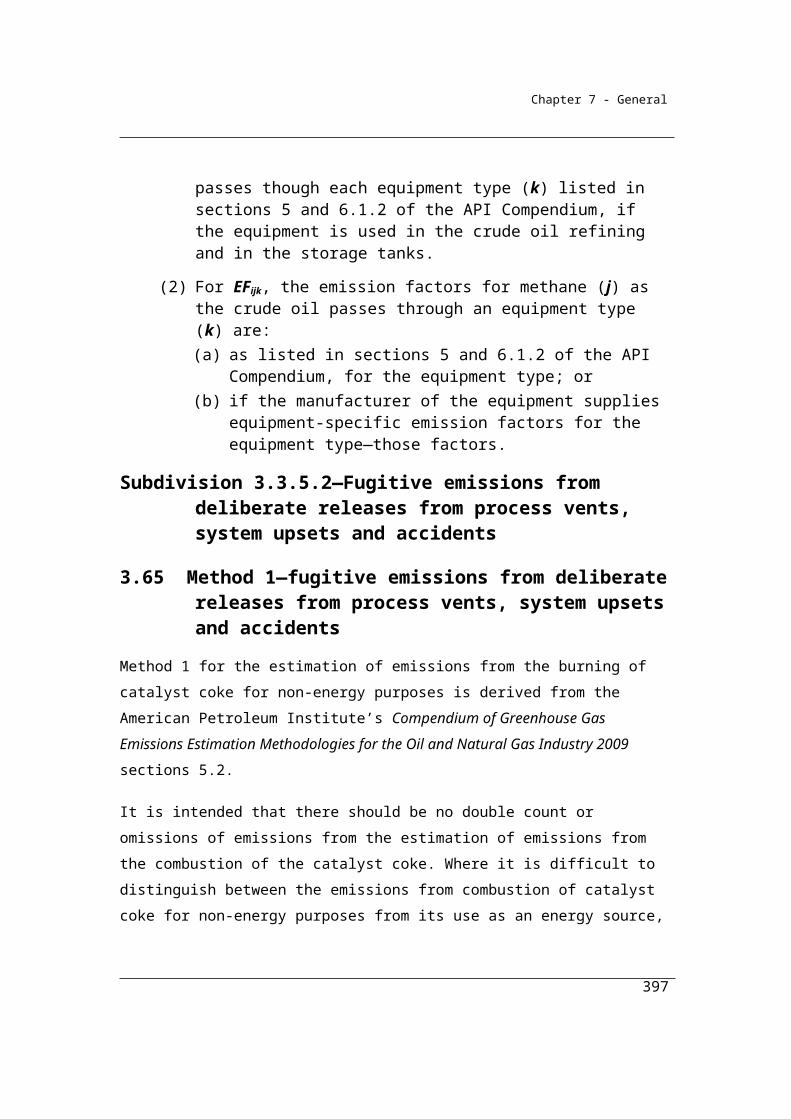
Chapter 7 - General
4.82 Method 3—aluminium (baked carbon anode production)
(1) Subject to this section, method 3 is the same as method 1 under section 4.80.
(2) In applying method 1 under section 4.80, the method for sampling and analysing the fuel type (i) for the factors Si and Ashi must be determined by sampling and analysing the fuel type for sulphur and ash content, as the case may be, in accordance with:
(a) for solid fuels—method 3 in Division 2.2.4; and(b) for gaseous fuels—method 3 in Division 2.3.4; and(c) for liquid fuels—method 3 in Division 2.4.4.
397

Chapter 7 - General
Division 4.4.4—Aluminium production (perfluoronated carbon compound emissions)Method 2 and Method 3 are to be drawn from the US Environment Protection Agency, Protocol for Measurement of Tetrafluoromethane (CF4) and Hexafluoroethane (C2F6) Emissions from Primary Aluminium Production as referenced in the International Aluminium Institute Greenhouse Gas Protocol.
4.83 Application
This Division applies to aluminium production.
Subdivision 4.4.4.1—Aluminium—emissions of tetrafluoromethane in aluminium production
4.84 Available methods
(1) Subject to section 1.18, one of the following methods must be used for estimating emissions of tetrafluoromethane released during a year from the operation of a facility that is constituted by the production of aluminium:(b) method 2 under section 4.86;(c) method 3 under section 4.87.
Note: There is no method 1 or 4 for this provision.
(2) However, for incidental emissions another method may be used that is consistent with the principles in section 1.13.
Summary of available methods, for estimating tetrafluoromethane emissions aluminium production, by emissions of gas type (j)
Tetrafluoromethane
Method 2 Section 4.86
Method 3 Section 4.87
398
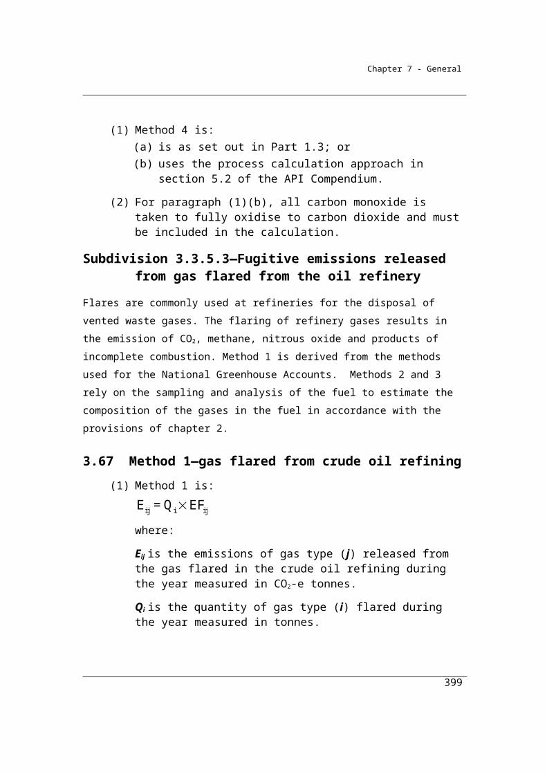
Chapter 7 - General
4.85 Method 1—aluminium (tetrafluoromethane)
Method 1 is:
ij ijiE = A EFwhere:
Eij is the amount of emissions of tetrafluoromethane released from primary aluminium production during the year measured in CO2-e tonnes.
Ai is the amount of primary aluminium production during the year measured in tonnes.
EFij is 0.30, which is the emission factor for tetrafluoromethane measured in CO2-e tonnes for each tonne of aluminium produced during the year.
4.86 Method 2—aluminium (tetrafluoromethane)
Method 2 is the Tier 2 method for estimating perfluorocarbon emissions as set out in the Perfluorocarbon protocol.
4.87 Method 3—aluminium (tetrafluoromethane)
Method 3 is the Tier 3 method for estimating facility-specific perfluorocarbon emissions as set out in the Perfluorocarbon protocol.
Subdivision 4.4.4.2—Aluminium—emissions of hexafluoroethane in aluminium production
4.88 Available methods
(1) Subject to section 1.18, one of the following methods must be used for estimating emissions of hexafluoroethane released during a year from the operation of a facility that is constituted by the production of aluminium:(b) method 2 under section 4.90;(c) method 3 under section 4.91.
Note: There is no method 1 or 4 for this provision.
(2) However, for incidental emissions another method may be used that is consistent with the principles in section 1.13.
399
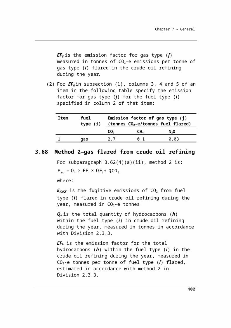
Chapter 7 - General
Summary of available methods, for estimating hexafluoroethane emissions aluminium production, by emissions of gas type (j)
Hexafluoroethane
Method 2 Section 4.90
Method 3 Section 4.91
4.89 Method 1—aluminium production (hexafluoroethane)
Method 1 is:
ij i ijE = A EFwhere:
Eij is the emissions of hexafluoroethane released from primary aluminium production during the year measured in CO2-e tonnes.
Ai is the amount of primary aluminium production during the year measured in tonnes.
EFij is 0.07, which is the emission factor for hexafluoroethane measured in CO2-e tonnes for each tonne of aluminium produced during the year.
4.90 Method 2—aluminium production (hexafluoroethane)
Method 2 is the Tier 2 method for estimating facility-specific perfluorocarbon emissions as set out in the Perfluorocarbon protocol.
4.91 Method 3—aluminium production (hexafluoroethane)
Method 3 is the Tier 3 method for estimating facility-specific perfluorocarbon emissions as set out in the Perfluorocarbon protocol.
400
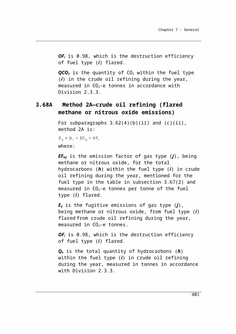
Chapter 7 - General
Division 4.4.5—Other metals production
4.92 Application
(1) This Division applies to emissions of carbon dioxide from any of the following:
(a) the consumption of a fossil fuel reductant;(b) the oxidation of a fossil fuel electrode.
(2) This Division does not apply to the production of any of the following:(a) aluminium;(b) ferroalloys;(c) iron;(d) steel;(e) any other metal produced using an integrated metalworks.
4.93 Available methods
(1) Subject to section 1.18, one of the following methods must be used for estimating emissions of carbon dioxide from the use of carbon reductants during a year from the operation of a facility that is constituted by the production of metals to which this Division applies:
(a) method 1 under section 4.94;(b) method 2 under section 4.95;(c) method 3 under section 4.96;(d) method 4 under Part 1.3.
(2) However, for incidental emissions another method may be used that is consistent with the principles in section 1.13.
401
Chapter 7 - General
Summary of available methods, for estimating emissions from other metal production, by emissions of gas type (j)
CO2 CH4 N2O
Method 1 Section 4.94 NO NO
Method 2 Section 4.95 NO NO
Method 3 Section 4.96 NO NO
Method 4 Method 4 under Part 1.3
NO NO
NO = Not occurring.
4.94 Method 1—other metals
Method 1, based on a carbon mass balance approach, is:Step 1 Work out the carbon content in fuel types (i) or carbonaceous input
material delivered for the activity during the year, measured in tonnes of carbon, as follows:
i i iCCF Q
where:i means the sum of the carbon content values obtained for all fuel types (i) or carbonaceous input material.CCFi is the carbon content factor mentioned in Schedule 3, measured in tonnes of carbon, for each appropriate unit of fuel type (i) or carbonaceous input material consumed during the year from the operation of the activity.Qi is the quantity of fuel type (i) or carbonaceous input material delivered for the activity during the year, measured in an appropriate unit and estimated in accordance with:
(a) criterion A in Divisions 2.2.5, 2.3.6 and 2.4.6; or(b) if the quantity of fuel or carbonaceous input material is not
acquired as part of a commercial transaction — industry practice, consistent with the principles in section 1.13.
Step 2 Work out the carbon content in products (p) leaving the activity during the year, measured in tonnes of carbon, as follows:
p p p CCF A
402
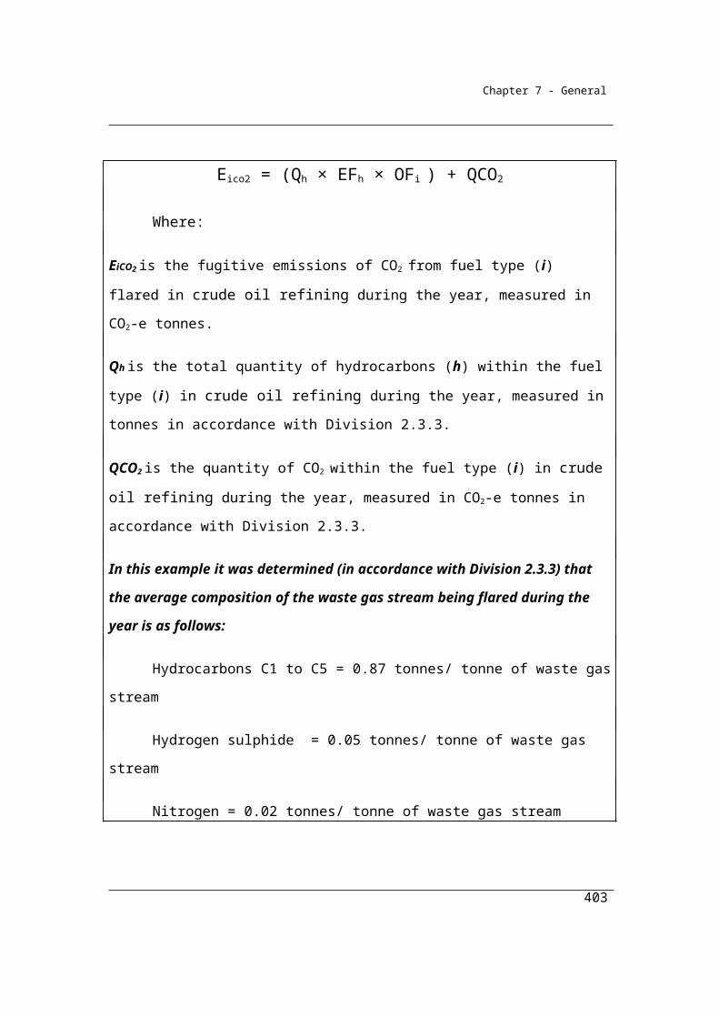
Chapter 7 - General
where:p means the sum of the carbon content values obtained for all product types (p).CCFp is the carbon content factor, measured in tonnes of carbon, for each tonne of product type (p) produced during the year.Ap is the quantity of product types (p) produced leaving the activity during the year, measured in tonnes.
Step 3 Work out the carbon content in waste by-product types (r) leaving the activity, other than as an emission of greenhouse gas, during the year, measured in tonnes of carbon, as follows:
r r r CCF Y
where:r means the sum of the carbon content values obtained for all waste by-product types (r).CCFr is the carbon content factor, measured in tonnes of carbon, for each tonne of waste by-product types (r).Yr is the quantity of waste by-product types (r) leaving the activity during the year, measured in tonnes.
Step 4 Work out the carbon content in the amount of the change in stocks of inputs, products and waste by-products held within the boundary of the activity during the year, measured in tonnes of carbon, as follows:
p p ap r r yri i qi CCF S + CCF S + CCF S
where:i has the same meaning as in step 1.CCFi has the same meaning as in step 1.ΔSqi is the change in stocks of fuel type (i) for the activity and held within the boundary of the activity during the year, measured in tonnes.
403
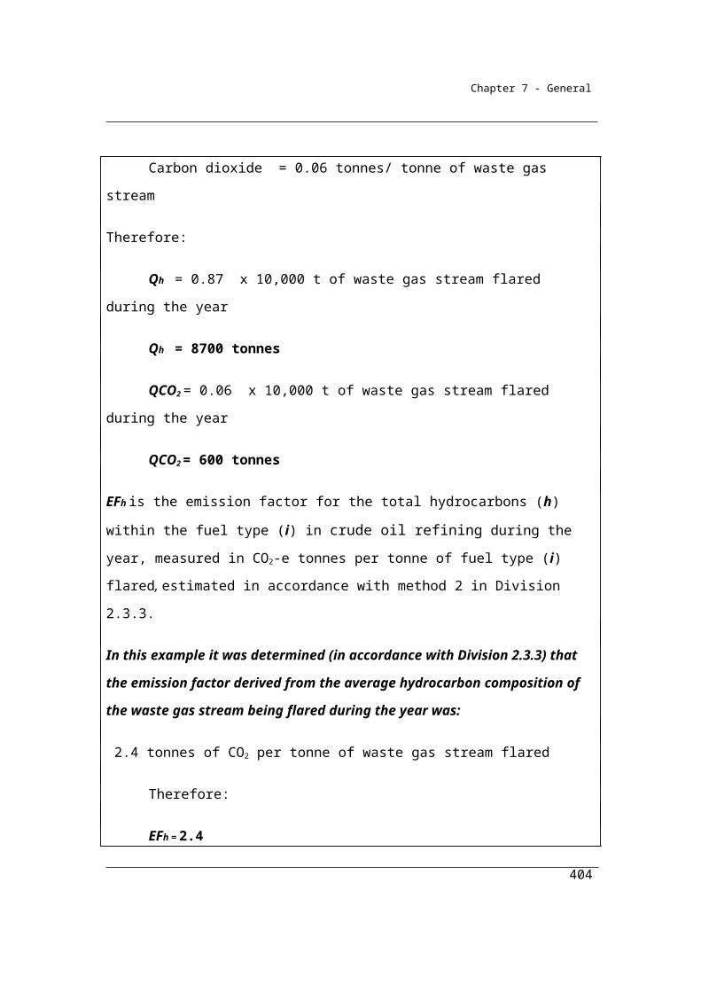
Chapter 7 - General
p has the same meaning as in step 2.CCFp has the same meaning as in step 2.ΔSap is the change in stocks of product types (p) produced by the activity and held within the boundary of the activity during the year, measured in tonnes.
r has the same meaning as in step 3.CCFr has the same meaning as in step 3.ΔSyr is the change in stocks of waste by-product types (r) produced from the operation of the activity and held within the boundary of the activity during the year, measured in tonnes.
Step 5 Work out the emissions of carbon dioxide released from the operation of the activity during the year, measured in CO2-e tonnes, as follows:
(a) add the amounts worked out under steps 2, 3 and 4 to work out a new amount (amount A);
(b) subtract amount A from the amount worked out under step 1 to work out a new amount (amount B);
(c) multiply amount B by 3.664 to work out the amount of emissions released from the operation of the activity during the year.
4.95 Method 2—other metals
(1) Subject to this section, method 2 is the same as method 1 under section 4.94.
(2) In applying method 1 as method 2, step 4 in section 4.94 is to be omitted and the following step 4 substituted.
Step 4 Work out the carbon content in the amount of the change in stocks of inputs, products and waste by-products held within the boundary of the activity during the year, measured in tonnes of carbon, as follows:
i i 2qi p p ap r r yr co CCF S + CCF S + CCF S + γRCCS
404
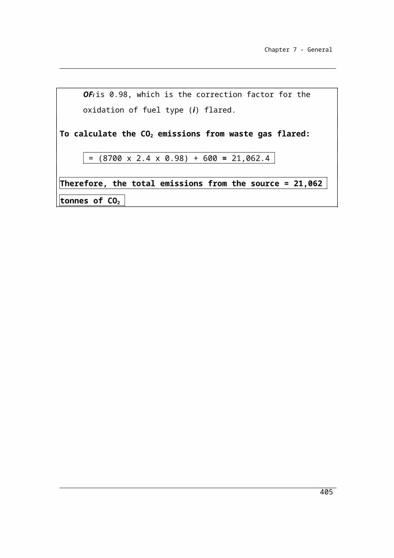
13.664
Chapter 7 - General
where:i has the same meaning as in step 1.CCFi has the same meaning as in step 1.ΔSqi is the change in stocks of fuel type (i) for the activity and held within the boundary of the activity during the year, measured in tonnes.p has the same meaning as in step 2.CCFp has the same meaning as in step 2.ΔSap is the change in stocks of product types (p) produced by the activity and held within the boundary of the activity during the year, measured in tonnes.r has the same meaning as in step 3.CCFr has the same meaning as in step 3.
ΔSyr is the change in stocks of waste by-product types (r) produced from the operation of the activity and held within the boundary of the activity during the year, measured in tonnes.α is the factor for converting the mass of carbon dioxide to a mass of carbon.γ is the factor 1.861 × 10⁻³ for converting a quantity of carbon dioxide from cubic metres at standard conditions of pressure and temperature to CO2-e tonnes.
RCCSCO2 is carbon dioxide captured for permanent storage, measured in cubic metres in accordance with Division 1.2.3.
(3) If a fuel type (i) or carbonaceous input material delivered for the activity during the year accounts for more than 5% of total carbon input for the activity, based on a calculation using the factors specified in Schedule 3, sampling and analysis of fuel type (i) or carbonaceous input material must be carried out to determine its carbon content.
(4) The sampling and analysis is to be carried out using the sampling and analysis provided for in Divisions 2.2.3, 2.3.3 and 2.4.3 that apply to the combustion of solid, gaseous and liquid fuels.
4.96 Method 3—other metals
(1) Subject to this section, method 3 is the same as method 2 under section 4.95.
405
Chapter 7 - General
(2) If a fuel type (i) or carbonaceous input material delivered for the activity during the year accounts for more than 5% of total carbon input for the activity, based on a calculation using the factors specified in Schedule 3, sampling and analysis of fuel type (i) or carbonaceous input material must be carried out to determine its carbon content.
(3) The sampling and analysis is to be carried out using the methods set out in Divisions 2.2.4, 2.3.4 and 2.4.4 that apply to the combustion of solid, gaseous and liquid fuels.
406
Chapter 7 - General
Part 4.5—Industrial processes—emissions of hydrofluorocarbons and sulphur hexafluoride gases
Emissions of hydrofluorocarbon (HFC) or sulphur hexafluoride (SF6) gases arise as fugitive emissions from the use of equipment, such as refrigeration, that contains these gases. Production of hydrofluorocarbons and sulphur hexafluoride currently does not occur in Australia.
4.97 Application
This Part applies to emissions of hydrofluorocarbons and sulphur hexafluoride gases.
4.98 Available method
(1) Subject to section 1.18, for estimating emissions of hydrofluorocarbons or sulphur hexafluoride during a year from the operation of a facility that is constituted by synthetic gas generating activities, one of the following methods must be used:
(a) method 1 under section 4.102;(b) method 2, for both hydrofluorocarbons and sulphur hexafluoride,
under section 4.103;(c) method 3:
(i) for hydrofluorocarbons under subsection 4.104(1); and(ii) for sulphur hexafluoride under subsection 4.104(2).
(2) However, for incidental emissions another method may be used that is consistent with the principles in section 1.13.Note: There is no method 4 for this Part.
4.99 Meaning of hydrofluorocarbons
Hydrofluorocarbons means any of the hydrofluorocarbons listed in the table in subsection 7A(2) of the Act.
407
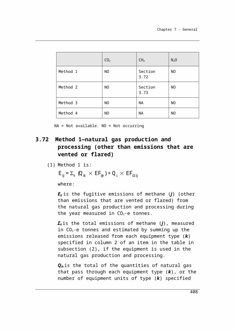
Chapter 7 - General
4.100 Meaning of synthetic gas generating activities
Only a subset of Reporters need to report estimates of emissions of hydrofluorocarbon gases. This reflects the assessment that the benefits of reporting may not exceed the costs of measurement in many instances given the large number of appliances that contain relatively small refrigerant charges, and the small share of total emissions that these emission sources would represent for many companies and facilities.
Emissions of hydrofluorocarbon gases need only be estimated if:
(a) hydrofluorocarbon gases are used in the equipment types specified in 4.102(4);
(b) the equipment type contains a refrigerant charge of more than 100 kilograms of refrigerants for each unit;
(c) the refrigerants have a weighted-average Global Warming Potential of over 1000; and
(d) the equipment is operated by a facility attributable to an ANZSIC classification listed in 4.100 (1) (b).
All users of SF6 should report SF6 emissions.
NGER methods are designed to be consistent with the provisions relating to Australia’s international reporting obligations. Under these obligations, the reportable gases are those specified in the IPCC second assessment report. As such, the list of gases does not include HCFC’s which are scheduled gases to be phased out under the Montreal Protocol.
The use of refrigerant blends is common in applications covered under NGERS. The table below lists a range of common blends and the constituents of each blend.
Summary of common refrigerant blends and their ingredients
Gas
Blend HFC125 HFC134a HFC143a HFC 32 Other (non HFC)
HFC-404A 44% 52% 4%
408
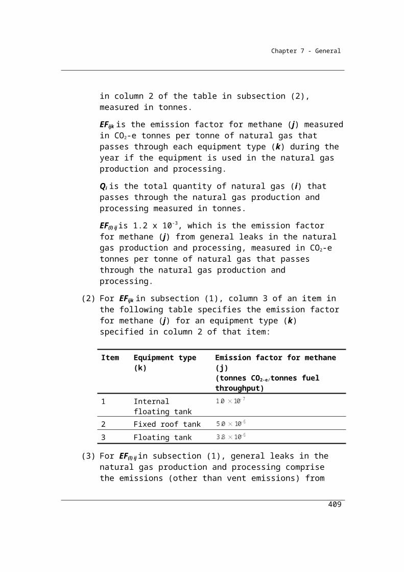
Chapter 7 - General
HFC-407A 40% 40% 20%
HFC-407C 25% 52% 23%
HFC-410A 50% 50%
HFC-413A 88% 12%
HFC-417A 47% 50% 3%
HFC-507A 50% 50%
HFC-407B 40% 40% 20%
Hydrofluorocarbons
(1) Synthetic gas generating activities, for emissions of hydrofluorocarbons, are activities of a facility that:
(a) require the use of any thing:(i) mentioned in paragraph 4.16(1)(a) of the Regulations; and
(ii) containing a refrigerant charge of more than 100 kilograms of refrigerants for each unit; and
(iii) using a refrigerant that is a greenhouse gas with a Global Warming Potential of more than 1 000; and
(b) are undertaken by a facility with a principal activity that is attributable to any one of the following ANZSIC industry classifications:(i) food product manufacturing (ANZSIC classification,
Subdivision 11);(ii) beverage and tobacco product manufacturing (ANZSIC
classification, Subdivision 12);(iii) retail trade (ANZSIC classification, Division G);(iv) warehousing and storage services (ANZSIC classification,
number 530);(v) wholesale trade (ANZSIC classification Division F);
(vi) rental, hiring and real estate services (ANZSIC classification, Division L).
Note: A facility with a principal activity that is not attributable to any one of the ANZSIC industry classifications mentioned in subparagraph (b(i), (ii), (iii), (iv), (v) or (vi) is not required to report emissions of hydrofluorocarbons.
409
Chapter 7 - General
Sulphur hexafluoride
(2) Synthetic gas generating activities, for emissions of sulphur hexafluoride, are any activities of a facility that:
(a) require the use of any equipment mentioned in paragraph 4.16(1)(d) of the Regulations; and
(b) emit sulphur hexafluoride.
4.101 Reporting threshold
These thresholds are intended to limit the application of the Part because of the large number of diverse and minor sources of emissions for this category.
For paragraph 4.22(1)(b) of the Regulations, the threshold mentioned in column 3 of an item in the following table resulting from a provision of this Determination mentioned in column 2 of that item is a reporting threshold.
Item Provision in Determination
Threshold
1 Subparagraph 4.100(1)(a)(ii)
100 kilograms for each unit (hydrofluorocarbons)
2 Subsection 4.100(2) Any emission (sulphur hexafluoride)
4.102 Method 1
Method 1 for emissions of HFCs and SF6 calculates emissions during the year using default leakage rates for the particular types of equipment within the facility. HFC and SF6 emissions should be estimated separately according to Method 1.
(1) Method 1 is:
jk jk jkE = Stock L
where:
Ejk is the emissions of gas type (j), either hydrofluorocarbons or sulphur hexafluoride, summed over each equipment type (k) during a year measured in CO2-e tonnes.
Stockjk is the stock of gas type (j), either hydrofluorocarbons or sulphur hexafluoride, contained in equipment type (k) during a year measured in CO2-e tonnes.
410
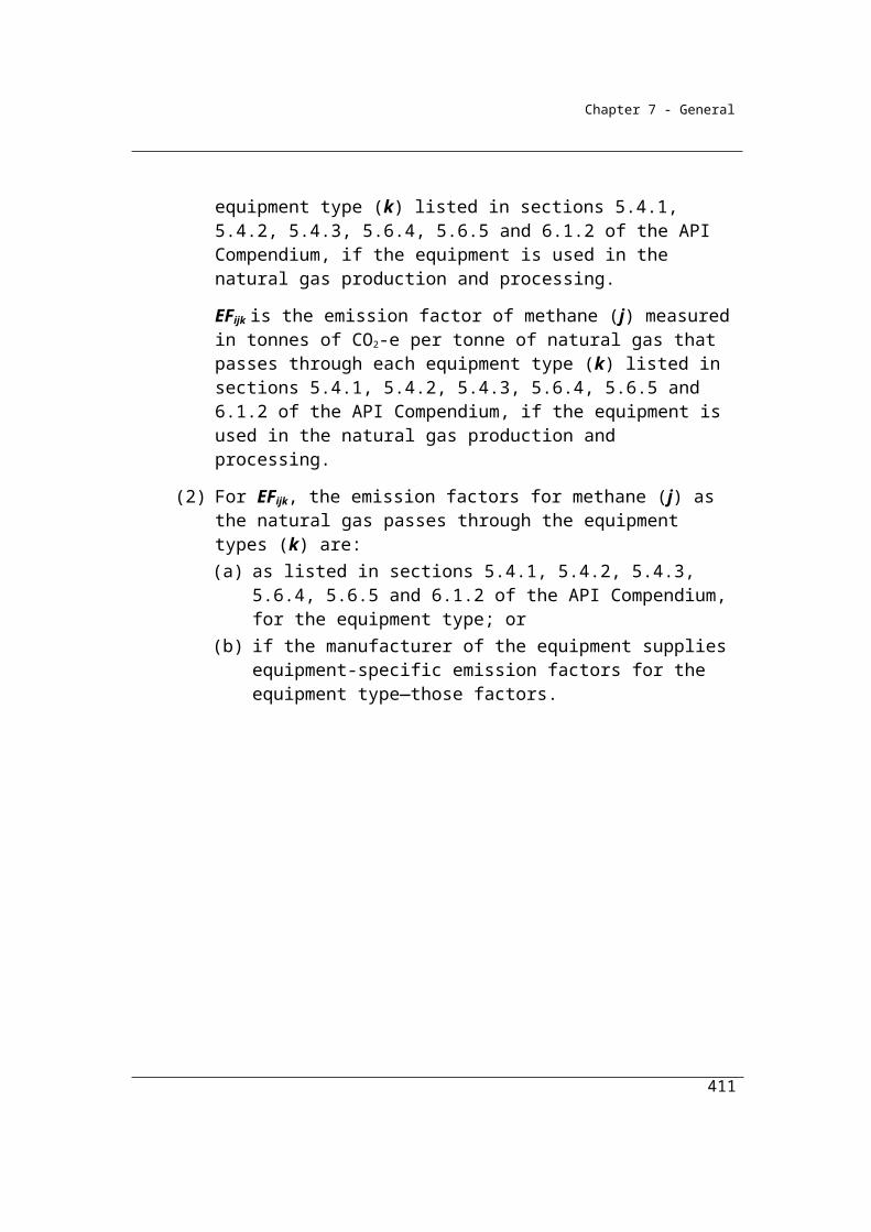
Chapter 7 - General
Ljk is the default leakage rates for a year of gas type (j) mentioned in columns 3 or 4 of an item in the table in subsection (4) for the equipment type (k) mentioned in column 2 for that item.
(2) For the factor Stockjk, an estimation of the stock of synthetic gases contained in an equipment type must be based on one of the following sources:
(a) the stated capacity of the equipment according to the manufacturer’s nameplate;
(b) estimates based on:(i) the opening stock of gas in the equipment; and
(ii) transfers into the facility from additions of gas from purchases of new equipment and replenishments; and
(iii) transfers out of the facility from disposal of equipment or gas.
(3) For equipment type (k), the equipment are the things mentioned in subregulation 4.16(1) of the Regulations.
(4) For subsection (1), columns 3 and 4 of an item in the following table set out default leakage rates of gas type (j), for either hydrofluorocarbons or sulphur hexafluoride, in relation to particular equipment types (k) mentioned in column 2 of the item:
Item Equipment type (k) Default annual leakage rate of gas (j)Hydrofluorocarbons
Sulphur hexafluoride
1 Commercial air conditioning
0.09
2 Commercial refrigeration 0.233 Industrial refrigeration 0.164 Gas insulated switchgear
and circuit breaker applications
0.0089
Both the type and quantity of hydrofluorocarbon or SF6 contained in the equipment should be shown on the equipment compliance plate. Quantities of hydrofluorocarbon or SF6 should be converted into CO2-e using the Global Warming Potentials listed in Appendix C. Where a refrigerant blend is used a worksheet for that particular refrigerant blend should be completed and a weighted average of the global warming potentials for each type of refrigerant in the blend should be used to convert to CO2-e.
411

Chapter 7 - General
Example
For a commercial refrigeration unit with a stock of 2 tonnes of HFC-23 the emissions in CO2-e tonnes are:
where:
Ejk is the emissions of gas type (j), either hydrofluorocarbons or sulphur hexafluoride, summed over each equipment type (k) during a year measured in CO2-e tonnes.
Stockjk is the stock of gas type (j), either hydrofluorocarbons or sulphur hexafluoride, contained in equipment type (k) during a year measured in CO2-e tonnes.
Ljk is the default leakage rates for a year of gas type (j) mentioned in columns 3 or 4 of an item in the table in subsection (4) for the equipment type (k) mentioned in column 2 for that item.
Convert the tonnes of HFC-23 to CO2-e tonnes using the global warming potential for HFC-23 listed in Appendix C
Stock = 2 x GWP
= 2 x 14,800
= 29,600 CO2-e tonnes
Emissions in CO2-e tonnes are:
= 24,000 x 0.23
= 8,880 t CO2-e
412
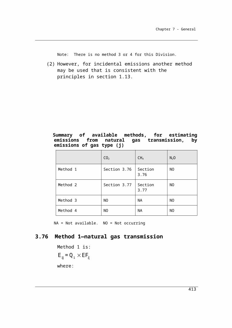
Chapter 7 - General
4.103 Method 2
The stock may also be estimated from mass balance calculations based on the opening stock of gas; transfers into the facility from additions of gas from purchases of new equipment and replenishments; and transfers out of the facility from disposal of equipment or gas. Method 2 uses the mass balance worksheet in Appendix A of the ENA Industry Guideline for SF6 Management and reporters should use this worksheet for both SF6 and hydrofluorocarbon gases. A separate worksheet should be completed for each type of gas.
Note that the total annual loss estimate (item F in the mass balance worksheet) for each type of gas should be converted into CO2-e using the Global Warming Potentials listed in Appendix C. Where a refrigerant blend is used a worksheet for that particular refrigerant blend should be completed and a weighted average of the global warming potentials for each type of HFC in the blend should be used to convert to CO2-e.
As the mass balance worksheet may not include all items for addition and subtraction applicable to the management of refrigerant systems (hydrofluorocarbons), Reporters of HFCs may modify the worksheet in order to obtain a more accurate estimate of emissions.
Storage means all equipment, cylinders and other containers which hold hydrofluorocarbons or SF6 not in use and which meet the requirements of 4.100 and 4.101.
For paragraph 4.98(1)(b), method 2 for estimating emissions of hydrofluorocarbons or sulphur hexafluoride during a year uses the tables in Appendix A of the publication entitled ENA Industry Guideline for SF6 Management, Energy Networks Association, 2008.
4.104 Method 3
Alternatively, emissions may be estimated from data on replenishments of gases in equipment as a proxy for leakage and using an assumption that the stock levels of gases within the equipment are maintained at constant levels in order to maintain constant operating efficiency levels. Method 3 uses this approach and refers
reporters of SF6 to the whole section in the ENA Industry Guideline for SF6
413
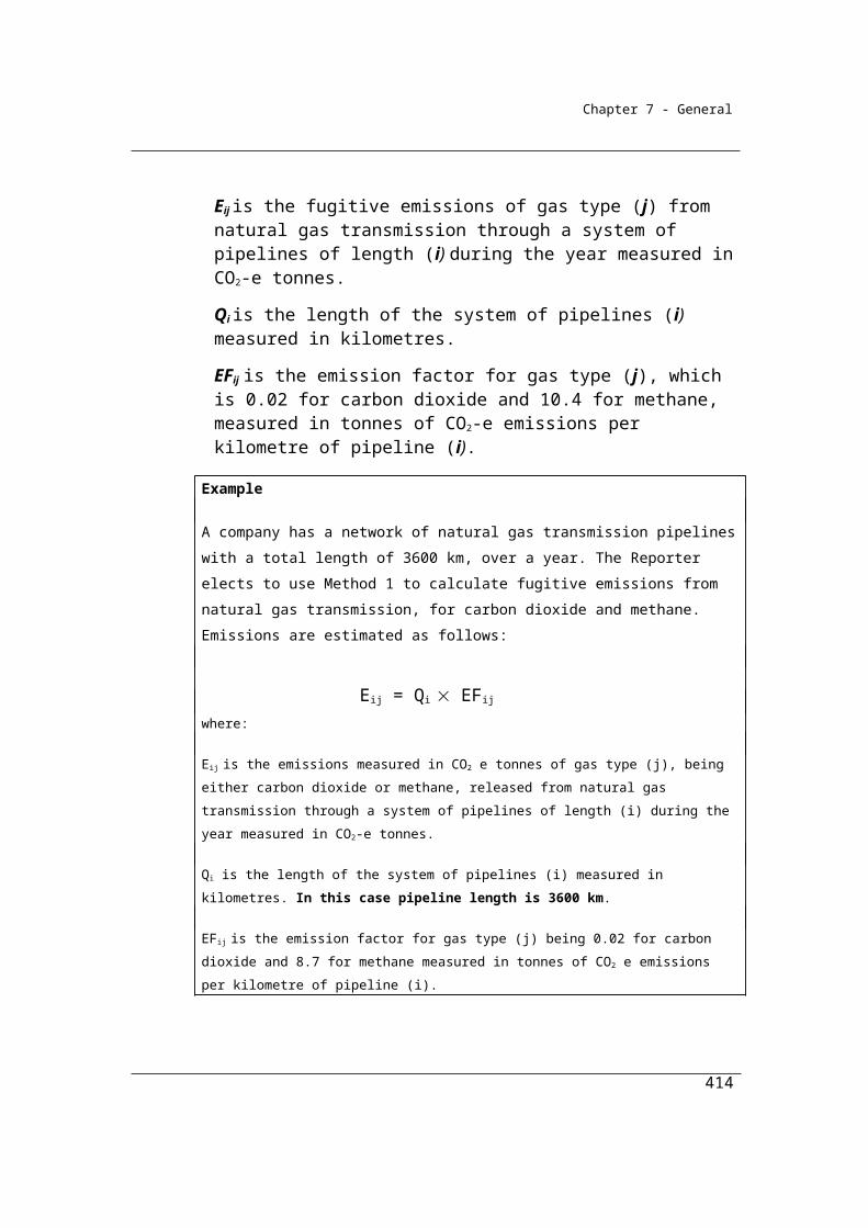
Chapter 7 - General
Management, section 6.3, which provides a discussion as well as a worksheet (by reference to Appendix B).
For reporters of HFCs, however, Method 3 simply references the worksheet in Appendix B of the ENA Industry Guideline for SF6 Management, and although it refers to SF6 can also be applied to HFCs.
A separate worksheet should be completed for each type of gas. The worksheet in Appendix B may not include all the point sources of losses for both SF6 and HFCs. Therefore this worksheet may be modified to include more point sources where they have been identified by the Reporter.
Note that the total annual loss of each type of gas should be converted into CO2-e using the Global Warming Potentials listed in Appendix C. Where a refrigerant blend is used a worksheet for that particular refrigerant blend should be completed and a weighted average of the global warming potentials for each type of HFC in the blend should be used to convert to CO2-e.
Storage means all equipment, cylinders and other containers which hold hydrofluorocarbons or SF6 not in use and which meet the requirements of 4.100 and 4.101.
(1) For paragraph 4.98(1)(c), method 3 for estimating emissions of hydrofluorocarbons uses the tables in Appendix B of the publication entitled ENA Industry Guideline for SF6 Management, Energy Networks Association, 2008.
(2) For paragraph 4.98(1)(c), method 3 for estimating emissions of sulphur hexafluoride during a year uses the Tier 3 method set out in section 6.3 of the publication mentioned in subsection (1).
414
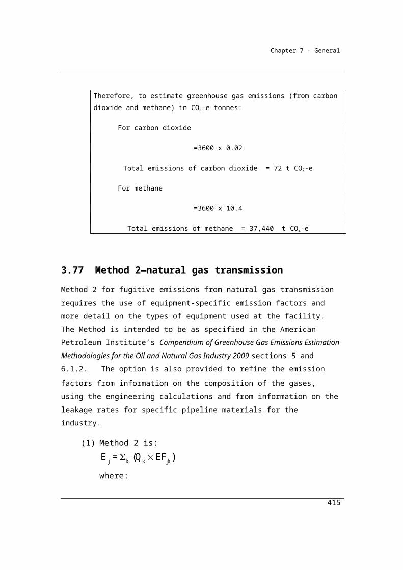
Chapter 7 - General
Chapter 5—Waste
Part 5.1—Preliminary
5.1 Outline of Chapter
This Chapter provides for emissions from the following sources:(a) solid waste disposal on land (see Part 5.2);(b) wastewater handling (domestic and commercial) (see Part 5.3);(c) wastewater handling (industrial) (see Part 5.4);(d) waste incineration (see Part 5.5).
Throughout the Waste chapter, emissions of CO2 generated from waste management are considered to be from biomass sources and therefore do not need to be estimated. For example, landfill gas comprises both methane and carbon dioxide but only the methane component should be reported.
Carbon dioxide produced from the flaring of methane from landfill gas or other emission sources in this chapter is also considered as having been derived from biomass sources and should not be reported.
Emissions of all gases arising from other, non-waste processes from the facility – such as emissions from the combustion of fuels for energy – must be estimated using methods described in the appropriate chapter of these Guidelines.
415
Chapter 7 - General
Part 5.2—Solid waste disposal on land
Division 5.2.1—Preliminary
5.2 Application
(1) This Part applies to emissions released from:(a) the decomposition of organic material from solid waste disposal in a
landfill; and(b) flaring of landfill gas.
(2) This Part does not apply to a landfill unless:(a) the landfill was open for the acceptance of waste on and after 1 July
2012; and(b) during a year the landfill emits more than 10 000 tonnes of CO2-e
from solid waste disposal at the landfill.
5.3 Available methods
(1) Subject to section 1.18 for estimating emissions released from the operation of a facility that is constituted by a landfill during a year:
(a) subject to paragraphs (c) and (d), one of the following methods must be used for emissions of methane from the landfill (other than from flaring of methane):(i) method 1 under section 5.4;
(ii) method 2 under section 5.15;(iii) method 3 under section 5.18; and
(b) one of the following methods must be used for emissions for each gas type released as a result of methane flared from the operation of the landfill:(i) method 1 under section 5.19;
(ii) method 2 under section 5.20;(iii) method 3 under section 5.21; and
(c) one of the following methods must be used for emissions from the biological treatment of solid waste at the landfill by an enclosed composting activity:(i) method 1 under section 5.22;
(ii) method 4 under section 5.22AA; and
416
Chapter 7 - General
(d) method 1 under section 5.22 must be used for emissions from the biological treatment of solid waste at the landfill by a composting activity that is not an enclosed composting activity.
(2) Under paragraph (1)(b), the same method must be used for estimating emissions of each gas type.
(3) For incidental emissions another method may be used that is consistent with the principles in section 1.13.Note: There is no method 4 for paragraphs (a) and (b). It is proposed that a method 4
will be developed in the future.
Summary of available methods, by emissions of gas type (j)
CO2 CH4 N2O
Solid waste disposal at landfill
Method 1 NA Section 5.4 NO
Method 2 NA Section 5.15 NO
Method 3 NA Section 5.18 NO
Method 4 NA NA NO
Methane flared from the operation of the landfill
Method 1 NA Section 5.19 Section 5.19
Method 2 NA Section 5.20 Section 5.20
Method 3 NA Section 5.21 Section 5.21
Method 4 NA NA NA
Biological treatment of solid waste
Method 1 NA Section 5.22 Section 5.22
NA = Not available or Not applicable. NO = Not occurring.
Future work
It is intended that methods for the direct monitoring of emissions at landfills be developed over time. No method 4 has been specified in the Determination. Further
417
Chapter 7 - General
development work and consultation is required to establish the appropriateness of various monitoring techniques before their inclusion.
418
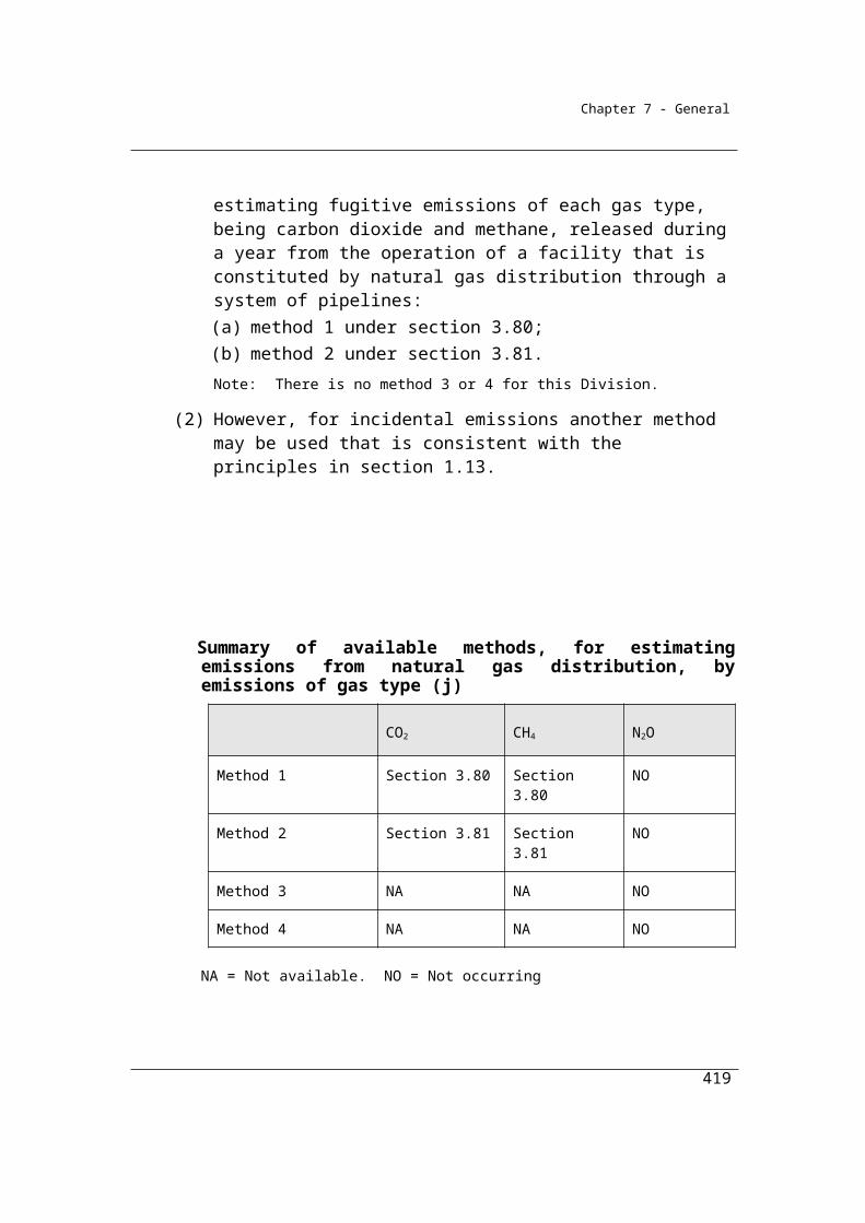
LOSSESADDITIONSOpening stock of degradable carbon Cos
New deposition of degradable carbon dCa
Emissions due to decay of opening stock ∆ Cos
Closing stock of degradable carbonCcs
Emissions due to decay of newly deposited carbon∆Ca
Food, garden, Wood, paper, textiles, sludge, nappies, rubber and leather and other carbonCa
Chapter 7 - General
Division 5.2.2—Method 1—emissions of methane released from landfills
Method 1 is consistent with the methods used for Australia’s National Greenhouse Accounts. It is intended that methane generated from solid waste disposal is estimated principally using data on the receipt of solid waste materials at the landfill (often required under State Government levy or reporting arrangements) and the First Order Decay (FOD) model provided in the 2006 IPCC Guidelines for National Greenhouse Gas Inventories, except in certain circumstances specified below.
The quantity of methane generated from solid waste disposal is estimated using a carbon mass balance approach consistent with the First Order Decay (FOD) model (IPCC 2006). Methane is generated by the decay of the decomposable degradable organic carbon stock in the landfill site and reflects waste disposal activity over many decades. The concept of the carbon stock model approach is illustrated in Figure 1.
Methane generated from the landfill at any point in time depends on the stock of decomposable degradable organic carbon inside the landfill. The opening stock of decomposable degradable organic carbon decays over the year (∆Cos) resulting in the generation of landfill gas with the remainder going to the year’s closing stock. Additionally, decomposable degradable organic carbon enters the landfill system through the deposition of new waste during the reporting year dCa. A portion of the newly deposited decomposable degradable organic carbon may decay in the reporting year ∆Ca and the remainder contributes to the closing stock of decomposable degradable organic carbon Ccs.
Figure 1: Carbon stock model flow chart
419
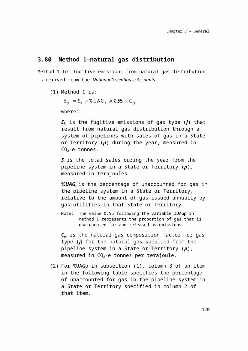
Chapter 7 - General
Principal method for estimation of emissions
The total change in decomposable degradable organic carbon stock is estimated simultaneously with estimated methane generation.
Methane generated at the landfill:
CH4 gen = (∆Ca(t) + ∆Cos(t)) F 1.336 x 21
Decomposable degradable organic carbon lost through decay during the year t:
∆Cos(t)= Cos(t) x (1−e−k)
∆Ca(t)= dCa(t) x [1−e −k x(13 −M) /12]
Accumulated decomposable degradable organic carbon at the landfill at the end of the year
Ccs(t) = Cos(t) – ∆Cos(t) + dCa(t) – ∆Ca(t)
Where:
CH4 gen is the quantity of methane generated at the landfill
(in tonnes of CO2-e)
dCa(t) is the quantity of decomposable degradable organic
carbon from newly deposited waste arriving at the landfill
and is derived using the equation:
dCa(t)= ∑i (Ca(t) x DOCFi x MCF)
420
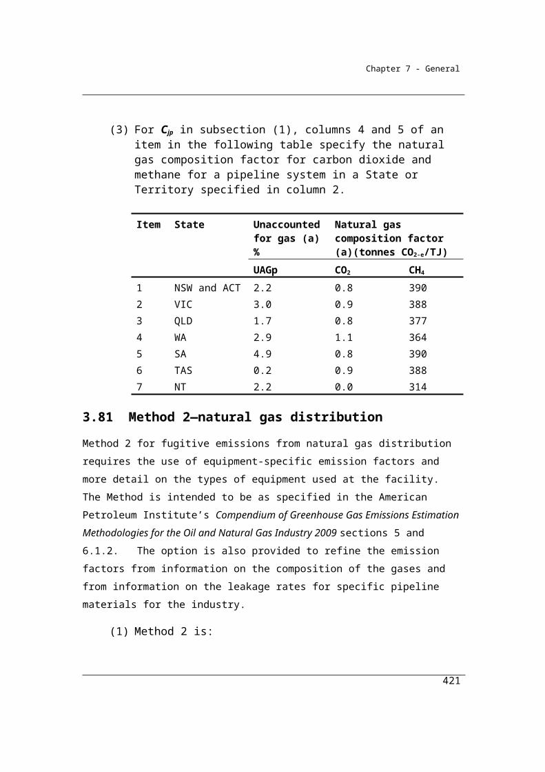
Chapter 7 - General
Where:
Ca(t) is the quantity of degradable organic carbon
in newly deposited waste at the landfill during the
year t (in tonnes)
DOCF is the fraction of degradable organic carbon dissimilated by waste mix type i (refer to section 5.14A).MCF is the methane correction factor for aerobic decomposition and is equal to 1.Sum for all waste types i.
∆Ca(t) is the quantity of decomposable degradable organic
carbon from newly deposited waste arriving at the landfill
lost through decay (decomposition) (in tonnes)
∆Cos(t) is the quantity of decomposable degradable organic
carbon from the opening stock of carbon at the landfill lost
through decay (decomposition) (in tonnes)
F is the fraction of CH4, by volume, generated in landfill
gas (and equal to 0.5)
1.336 is the conversion factor from a mass of C to a mass of
CH4
Cos(t) is the quantity of decomposable degradable organic
carbon accumulated in the landfill at the beginning of the
year t (in tonnes)
Ccs(t) is the quantity of decomposable degradable organic
carbon accumulated in the landfill at the end of the year t
(in tonnes)
421
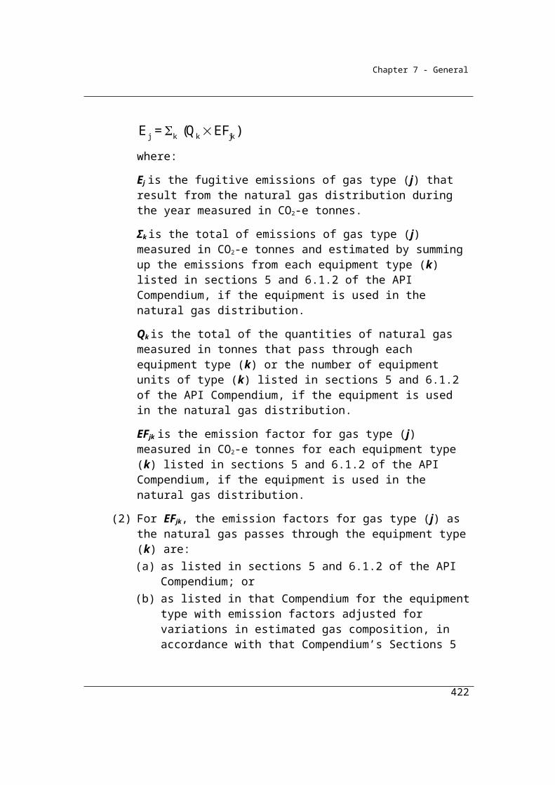
Chapter 7 - General
Ca(t) is the quantity of decomposable degradable organic
carbon in newly deposited waste at the landfill during the
year t (in tonnes)
The opening stock of degradable organic carbon for a year
Cos(t) is equal to the closing stock Ccs(t-1) of the previous
year
M = month when decay process commences, equal to the
average delay time (months) + 7. Landfill operators may
choose an appropriate value for average delay time between
0 and 12. In the absence of information on delay time, a
value of 6 months may be used for average delay time (M =
13).
k = methane generation constant
t = year t (reporting year)
The FOD model estimates CH4 generated in any given year by adding the newly deposited waste (dCa) into the disposal site in one year to the waste left over from the previous year (which is taken as the current year’s opening stock – Cos). The CH4 generation for the year is then calculated from this ‘running total’ of the decomposable degradable organic carbon remaining in the site.
The basis for this approach lies in the first order reaction. With a first order reaction the amount of product (here degradable organic carbon decomposed - ∆Ca(t) + ∆Cos(t)) - is always proportional to the amount of reactant (here Cos + dCa).
Alternative method for estimation of emissions
Section 5.4 also sets out the circumstances in which an alternative approach to the estimation of emissions will apply. The alternative approach will apply to a facility that captures methane generated by the landfill and where the estimates of the
422
Chapter 7 - General
quantity of methane captured for combustion (either at the landfill or elsewhere) and from flaring exceed 75 per cent of the estimated emissions generated by the landfill according to the application of the Tier 2 FOD model.
If the 75 per cent threshold is exceeded, (that is, if the quantity of methane captured, transferred offsite or flared exceeds 75 per cent of the estimated methane generated at the landfill) then it is intended that emissions would be estimated as [1/0.75] multiplied by the quantity of methane captured.
Where this threshold has been triggered, it is also important to track the carbon loss (∆Cos(t)) associated with the estimated emissions. Sections 5.4B and 5.4C of the Determination provide instructions on performing this calculation.
This alternative approach ensures that where a more accurate estimate of emissions generated by the landfill is available – i.e. based on the quantity of emissions captured – that this better data is substituted for the Tier 2 FOD model-generated emissions data.
The choice of 75 per cent as the threshold value reflects advice in the Department of Environment and Heritage publication, National Pollution Inventory – Emission Estimation Manual for Municipal Solid Waste (MSW) Landfills, Version 1.2, May 2005 that this constitutes the most common assumption about capture efficiency of landfill sites. A similar approach has recently been adopted by the US Environment Protection Agency.
It is intended that Reporters will be able to use higher-order methods – in particular, method 2 – to establish higher capture efficiencies. A capture efficiency limit of 85 per cent has been established under method-2. Under the method-2 provisions in the Determination, site-specific k values obtained under method-2 would be derived once only. The establishment of the 85% capture efficiency limit is designed to ensure that methane capture does not exceed methane generation at any time in the future.
5.4 Method 1—methane released from landfills (other than from flaring of methane)
(1) For subparagraph 5.3(1)(a)(i), method 1 is:
423
Chapter 7 - General
*cap tr4j flaredE = CH (Q + Q + Q ) (1 OF)
where:
Ej is the emissions of methane released by the landfill during the year measured in CO2-e tonnes.
CH4* is the estimated quantity of methane in landfill gas generated by the landfill during the year as determined under subsection (2) or (3) and measured in CO2-e tonnes.
γ is the factor 6.784 × 10-4 × 25 converting cubic metres of methane at standard conditions to CO2-e tonnes.
Qcap is the quantity of methane in landfill gas captured for combustion from the landfill during the year and measured in cubic metres in accordance with Division 2.3.6.
Qflared is the quantity of methane in landfill gas flared from the landfill during the year and measured in cubic metres in accordance with Division 2.3.6.
Qtr is the quantity of methane in landfill gas transferred out of the landfill during the year and measured in cubic metres in accordance with Division 2.3.6.
OF is the oxidation factor (0.1) for near surface methane in the landfill.
(2) For subsection (1), if:
cap trflared
4gen
(Q + Q + Q )CH
is less than or equal to 0.75, then:*
4 4genCH = CH
where:
CH4gen is the quantity of methane in landfill gas generation released from the landfill during the year estimated in accordance with subsection (5) and measured in CO2-e tonnes.
(3) For subsection (1), if:
cap trflared
4gen
(Q + Q + Q )CH
424
Chapter 7 - General
is greater than 0.75, then:
*flared trcap4 + Q + Q 1CH = Q
0.75
where:
γ is the factor 6.784 x 10-4 x 25 converting cubic metres of methane at standard conditions to CO2-e tonnes.
Qcap is the quantity of methane in landfill gas captured for combustion from the landfill during the year and measured in cubic metres.
(4) For subsections (1) and (3), Qcap is to be calculated in accordance with Division 2.3.6.
(5) For subsection (2), CH4gen must be calculated using the estimates mentioned in section 5.4A and the equations mentioned in sections 5.4B, 5.4C and 5.4D.
5.4A Estimates for calculating CH4gen
For subsection 5.4(5), the estimates for calculating CH4gen are the following:
(a) the tonnage of total solid waste disposed of in the landfill during the year estimated in accordance with section 5.5;
(b) the composition of the solid waste disposed of in the landfill during the year estimated in accordance with section 5.9;
(c) the degradable organic carbon content of the solid waste disposed of in the landfill by waste type estimated in accordance with section 5.12;
(d) the opening stock of degradable organic carbon in the solid waste at the landfill at the start of the first reporting period for the landfill estimated in accordance with section 5.13;
(e) methane generation constants (k values) for the solid waste at the landfill estimated in accordance with section 5.14;
(f) the fraction of degradable organic carbon dissimilated (DOCF) estimated in accordance with section 5.14A;
(g) the methane correction factor for aerobic decomposition in the first year estimated in accordance with section 5.14B;
(h) the fraction by volume of methane generated in landfill gas estimated in accordance with section 5.14C;
(i) the number of months that have ended before methane generation at the landfill commences estimated in accordance with section 5.14D.
425
Chapter 7 - General
5.4B Equation—change in quantity of particular opening stock at landfill for calculating CH4gen
(1) For subsection 5.4(5), this section applies if the result of the first equation in subsection 5.4(3)is, for the reporting year for which the result is calculated, (the current reporting year), greater than 0.75.
(2) The change in the quantity of the opening stock of decomposable degradable organic carbon (∆Cost) that is:
(a) located in the landfill during the reporting year; and(b) measured in tonnes; and(c) lost through decomposition;
must be calculated using the equation mentioned in subsection (3).
(3) For subsection (2), the equation is:
where:
t is the reporting year.
CH4* is the estimated quantity of methane in landfill gas generated by the landfill during the year, measured in CO2-e tonnes.
F is the fraction of methane generated in landfill gas estimated in accordance with section 5.14C.
1.336 is the factor to convert a mass of carbon to a mass of methane.
25 is the factor to convert methane to carbon dioxide equivalent.Note 1: For the definition of reporting year, see the National Greenhouse and Energy
Reporting Regulations 2008.
Note 2: If the result of the first equation in subsection 5.4(3):(a) was, for a previous reporting year or years, greater than 0.75; and(b) is, for the current reporting year, less than or equal to 0.75;
use:(c) the calculation in section 5.4B to calculate the change in the opening
stock of carbon for the final reporting year in which the result of that equation is greater than 0.75; and
(d) the calculation in section 5.4C to calculate the closing stock for that reporting year.
426
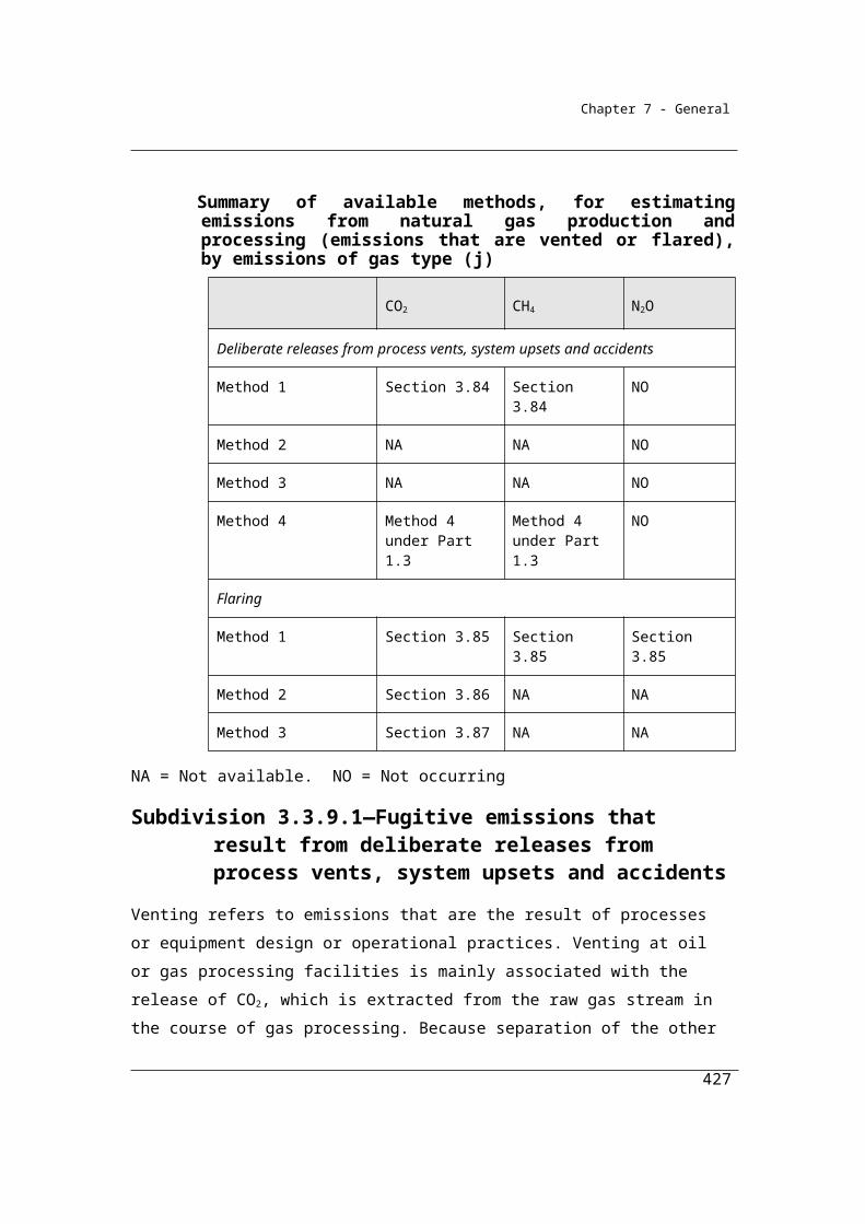
Chapter 7 - General
5.4C Equation—quantity of closing stock at landfill in particular reporting year
(1) For subsection 5.4(5), this section applies if the result of the first equation in subsection 5.4(3) is, for the reporting year for which the result is calculated, (the current reporting year), greater than 0.75.
(2) The quantity of closing stock of decomposable degradable organic carbon (Ccst) in the most recent year to which subsection 5.4(3) applies:
(a) located in the landfill during the reporting year; and(b) measured in tonnes;
must be calculated using the equation mentioned in subsection (3):
(3) For subsection (2), the equation is:
ostcst ostC = C C
where:
Ccst is the closing stock of carbon in the last year in which subsection 5.4(3) was used to calculate emissions.
Cost is the opening stock of carbon in the first year in which 5.4(3) was used to calculate emissions.
∆Cost is the change in carbon stock for all years in which 5.4(3) applies and is estimated in accordance with 5.4B.Note: The quantity of closing stock calculated in accordance with this section is the
same as the quantity of opening stock for the current reporting year.
Guidance on using Ccst calculated according to 5.4C in the FOD model.
As the FOD model tracks the decay of individual waste mix types, it is necessary to
calculate a closing stock of carbon (Ccst) for each waste mix type. This may be done
by allocating ΔCost to each waste mix type on the basis of the proportions of Ccst
by waste mix type for the year preceding the first year in which the 75 per cent
capture rule is triggered.
If there are no preceding years in which capture was below 75 per cent, Ccst may be
allocated to each waste mix type according to the waste composition.
427
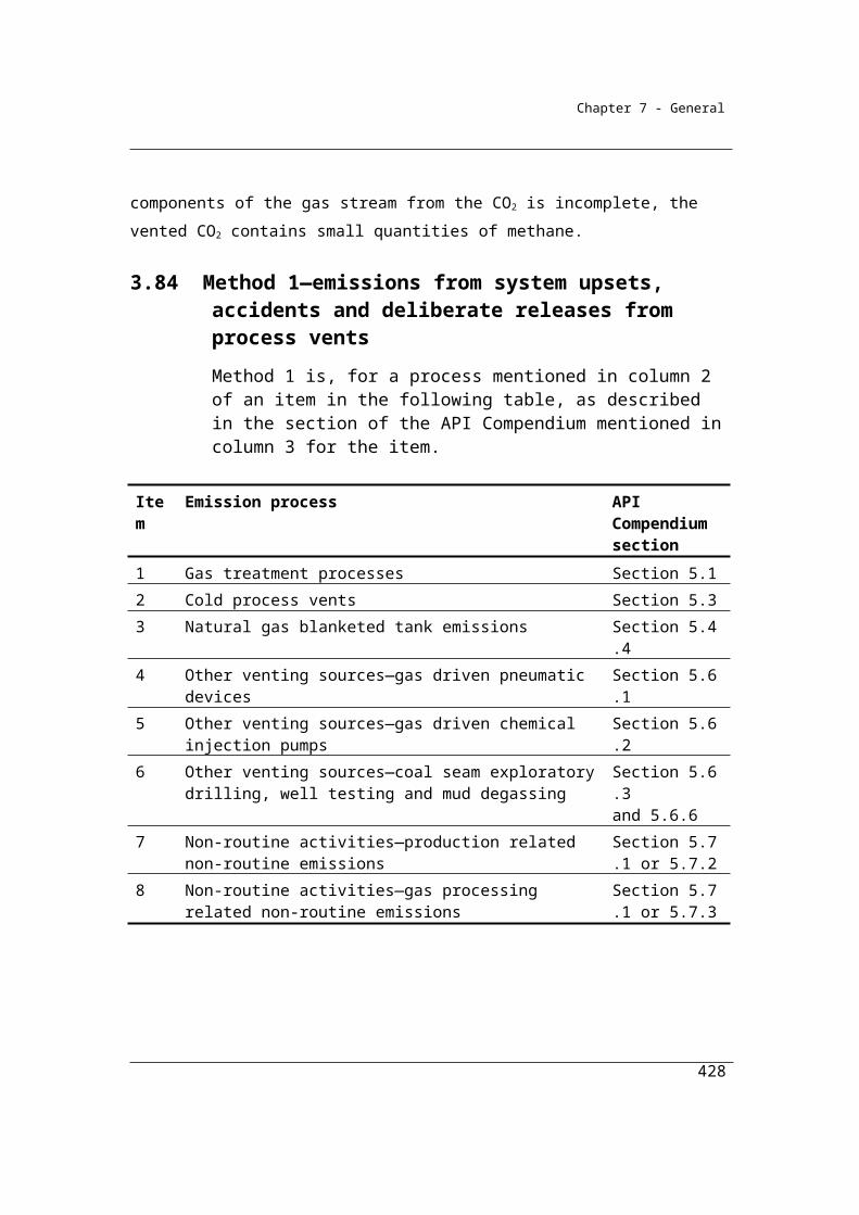
Chapter 7 - General
5.4D Equation—quantity of methane generated by landfill for calculating CH4gen
For subsection 5.4(5), the quantity of methane generated by the landfill must be calculated using the following equation:
where:
CH4gen is the quantity of methane generated by the landfill as calculated under this section and measured in CO2-e tonnes.
F is the fraction of methane generated in landfill gas estimated in accordance with section 5.14C.
1.336 is the factor to convert a mass of carbon to a mass of methane.
25 is the factor to convert methane to carbon dioxide equivalent.
∆Cost is the change in the quantity of the opening stock of decomposable degradable organic carbon derived from the sum of all waste mix types located in the landfill during the reporting year, measured in tonnes, lost through decomposition, and equals:
∆Cost = ∑i Cosit (1−e−ki)where:
Cosit is the quantity of decomposable degradable organic carbon accumulated in the landfill at the beginning of the reporting year from all waste mix types mentioned in subsection 5.11(1), measured in tonnes and equals:
Cosit = Ccsit-1
where:
Ccsit-1 is the closing stock of decomposable degradable organic carbon accumulated in the landfill in the year immediately preceding the reporting year from all waste mix types mentioned in subsection 5.11(1), measured in tonnes and equals:
Ccsit = Cosit – ∆Cosit + Cait – ∆Cait
and:
428
Chapter 7 - General
∆Cat is the change in the quantity of decomposable degradable organic carbon derived from the sum of all waste mix types deposited at the landfill during the reporting year, measured in tonnes, lost through decomposition, and equals:
∆Cat = ∑i Cait [1−e –ki (13 – M) /12]where:
Cait is the quantity of degradable organic carbon in all waste mix types mentioned in subsection 5.11(1) deposited at the landfill during the reporting year , measured in tonnes and is equal to:
Cait = (Qit DOCi DOCfi MCF)
where:
Qit is the quantity of all waste mix types mentioned in subsection 5.11(1) deposited at the landfill during the reporting year, measured in tonnes.
DOCi is the fraction of the degradable organic carbon content of the solid waste for all waste mix types mentioned in subsection 5.11(1) and deposited at the landfill.
DOCfi is the fraction of decomposable degradable organic carbon for all waste mix types mentioned in subsection 5.11(1).
MCF is the methane correction factor for aerobic decomposition for the facility during the reporting year.and where:
ki is the methane generation constant for all waste mix types mentioned in subsection 5.11(1).
t is the reporting year.
M is the number of months before commencement of methane generation at the landfill plus 7.
Σi is the sum for all waste mix types mentioned in subsection 5.11(1).Note 1: For the definition of reporting year, see the National Greenhouse and Energy
Reporting Regulations 2008.
Note 2: For the source of the equation included in:(a) section 5.4D, see Volume 5, Chapter 3 of the 2006 IPCC Guidelines,
equation 3.6; and(b) the definition of ∆Cost, see Volume 5, Chapter 3 of the 2006 IPCC
Guidelines, equation 3.5; and(c) the definition of ∆Cat, see Volume 5, Chapter 3 of the 2006 IPCC
Guidelines, equation 3.A1.13; and
429
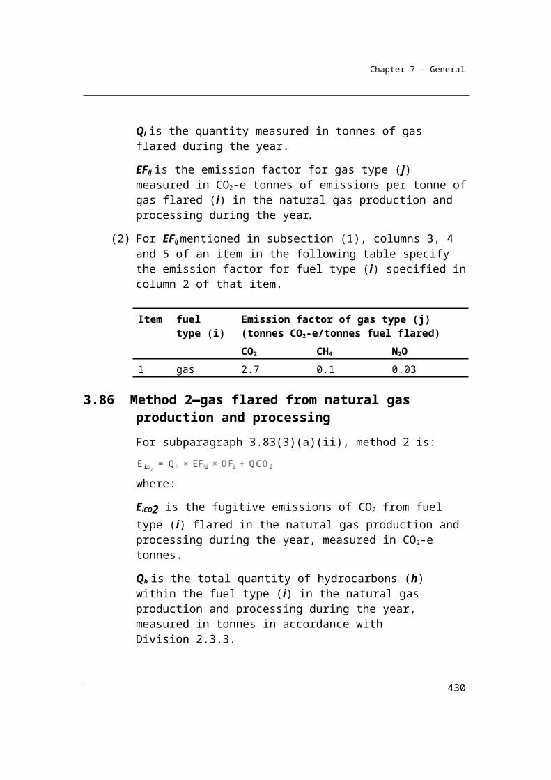
Chapter 7 - General
(d) the definition of ∆Cait, see Volume 5, Chapter 3 of the 2006 IPCC Guidelines, equation 3.2.
Note 3: For each reporting year to which subsection 5.4(3) applies, use the equation mentioned in section 5.4B
Note 4: If the result of the first equation in subsection 5.4(3):(a) was, for a previous reporting year or years, greater than 0.75; and(b) is, for the reporting year for which the result is calculated, (the current
reporting year), less than or equal to 0.75;
use:(c) the calculation in section 5.4B to calculate the change in the opening
stock of carbon for the final reporting year in which the result of that equation is greater than 0.75; and
(d) the calculation in section 5.4C to calculate the closing stock for that reporting year.
Sections 5.5 – 5.8 set out the criterion available for estimating the tonnage of total solid waste received at the landfill. However, the tonnage of waste disposed of in a landfill is required by the IPCC Tier 2 FOD model. Reporters can determine the amount of waste disposed of in a landfill by subtracting the amount of waste diverted from disposal in a landfill from the amount of waste received at the landfill. Section 5.11A sets out the parameters available to make such deductions. This concept is best clarified by the following:
Waste disposed of in a landfill = waste received at the landfill – waste diverted from disposal (i.e. the quantity of material that is composted, recycled or used onsite).
According to the NGER Regulations, it is necessary to report the amount of waste entering (disposed at) the landfill and the amount of waste received at the landfill for treatment (either onsite or offsite) or use (waste diverted) when submitting an NGER Report. Consequently, it is necessary to report both of these values into the NGER Solid Waste Calculator. The Clean Energy Regulator can provide further advice about the correct use of the NGERS solid waste calculator.
5.5 Criteria for estimating tonnage of total solid waste
For the purpose of estimating the tonnage of waste disposed of in a landfill, the tonnage of total solid waste received at the landfill during the year is to be estimated using one of the following criteria:
(a) as provided in section 5.6 (criterion A);
430
Chapter 7 - General
(b) as provided in section 5.7 (criterion AAA);(c) as provided in section 5.8 (criterion BBB).
5.6 Criterion A
For paragraph 5.5(a), criterion A is:(a) the amount of solid waste received at the landfill during the year as
evidenced by invoices; or(b) if the amount of solid waste received at the landfill during the year is
measured in accordance with State or Territory legislation applying to the landfill—that measurement.
5.7 Criterion AAA
For paragraph 5.5(b), criterion AAA is the direct measurement of quantities of solid waste received at the landfill during the year using measuring equipment calibrated to a measurement requirement.
5.8 Criterion BBB
For paragraph 5.5(c), criterion BBB is the estimation of solid waste received at the landfill during the year in accordance with industry estimation practices (such as the use of accepted industry weighbridges, receipts, invoices, other documents or records or population and per-capita waste generation rates).
5.9 Composition of solid waste
Sections 5.9 – 5.10 set out data requirements for the composition of the waste data split between general and homogenous waste streams. General waste stream data required include tonnes of (a) municipal solid waste (b) commercial and industrial waste and (c) construction and demolition waste. Homogenous waste stream data required include tonnes of (a) shredder flock (b) alternative waste treatment residues and (c) inert waste.
It is intended that Reporters should adopt the classifications adopted for state-based levy systems where applicable and if not, classify waste according to the principle activity leading to the generation of the waste. For example:;
• Waste from domestic premises, council collections and other municipal sources may be classed as municipal solid waste;
431
Chapter 7 - General
• Waste from composting or biological treatment facilities may be classed as alternative waste treatment residues;
• Waste from scrap metal recycling facilities may be classed as shredder flock.
The Australian, New Zealand Standard Industry Classification (ANZSIC) system may also be useful in classifying the waste generating activities. For example:;
• Waste from activities within ANZSIC divisions C, G or H may be classified as commercial and industrial waste;
• Waste from activities within ANZSIC division E may be classified as construction and demolition waste;
•waste from mixed load deliveries of domestic and commercial waste should be classed according to the dominant source.
(1) For paragraph 5.4A(b), the composition of solid waste received at the landfill during the year must be classified by:
(a) the general waste streams mentioned in subsection 5.10(1); and(b) the homogenous waste streams mentioned in subsection 5.10A(1).
(2) For solid waste received at the landfill during a year, an estimate of tonnage of:
(a) each general waste stream must be provided in accordance with section 5.10; and
(b) each homogenous waste stream must be provided in accordance with section 5.10A.
(3) For the following general and homogenous waste streams there must be a further classification in accordance with section 5.11 showing the waste mix types in each waste stream (expressed as a percentage of the total tonnage of solid waste in the waste stream):
(a) municipal solid waste class I;(ab) municipal solid waste class II;(b) commercial and industrial waste;(c) construction and demolition waste;(d) shredder flock.
432
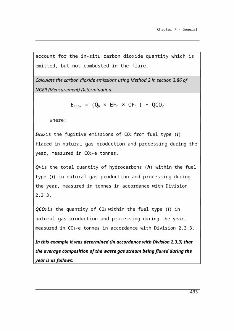
Chapter 7 - General
5.10 General waste streams
(1) For paragraph 5.9(1)(a), the general waste streams are as follows:(a) municipal solid waste class I;
(ab) municipal solid waste class II;(b) commercial and industrial waste;(c) construction and demolition waste.
(2) Subject to subsection (3), for paragraph 5.9(2)(a), the tonnage of each waste stream mentioned in subsection (1) must be estimated:
(a) if the operator of the landfill is required, under a law of the State or Territory in which the landfill is located, to collect data on tonnage of waste received at the landfill according to the waste streams mentioned in subsection (1)—by using that data; or
(b) if paragraph (a) does not apply and the operator of the landfill is able to estimate, in accordance with one of the criteria set out in section 5.5, the tonnage of the waste streams mentioned in subsection (1)—by using that criterion; or
(c) if paragraphs (a) and (b) do not apply and there is no restriction on the waste streams that can be received at the landfill—by:(i) for estimating the tonnage of the municipal solid waste class I
stream if the landfill did not receive municipal solid waste class II—using the percentage value specified in columns 2 to 9 of item 1 of the following table for the State or Territory in which the landfill is located; and
(ii) for estimating the tonnage of the municipal solid waste class II stream if the landfill did not receive municipal solid waste class I—using the percentage value specified in columns 2 to 9 of item 1 of the following table for the State or Territory in which the landfill is located; and
(iii) for estimating the tonnage of the municipal solid waste class I stream and the municipal solid waste class II stream if the landfill received both municipal solid waste classes—halving the percentage value specified in columns 2 to 9 of item 1 of the following table for the State or Territory in which the landfill is located and using that value for each of the municipal solid waste streams; and
(iv) for estimating the tonnage of the commercial and industrial waste stream—using the percentage value specified in columns 2 to 9 of item 2 of the following table for the State or Territory in which the landfill is located; and
433
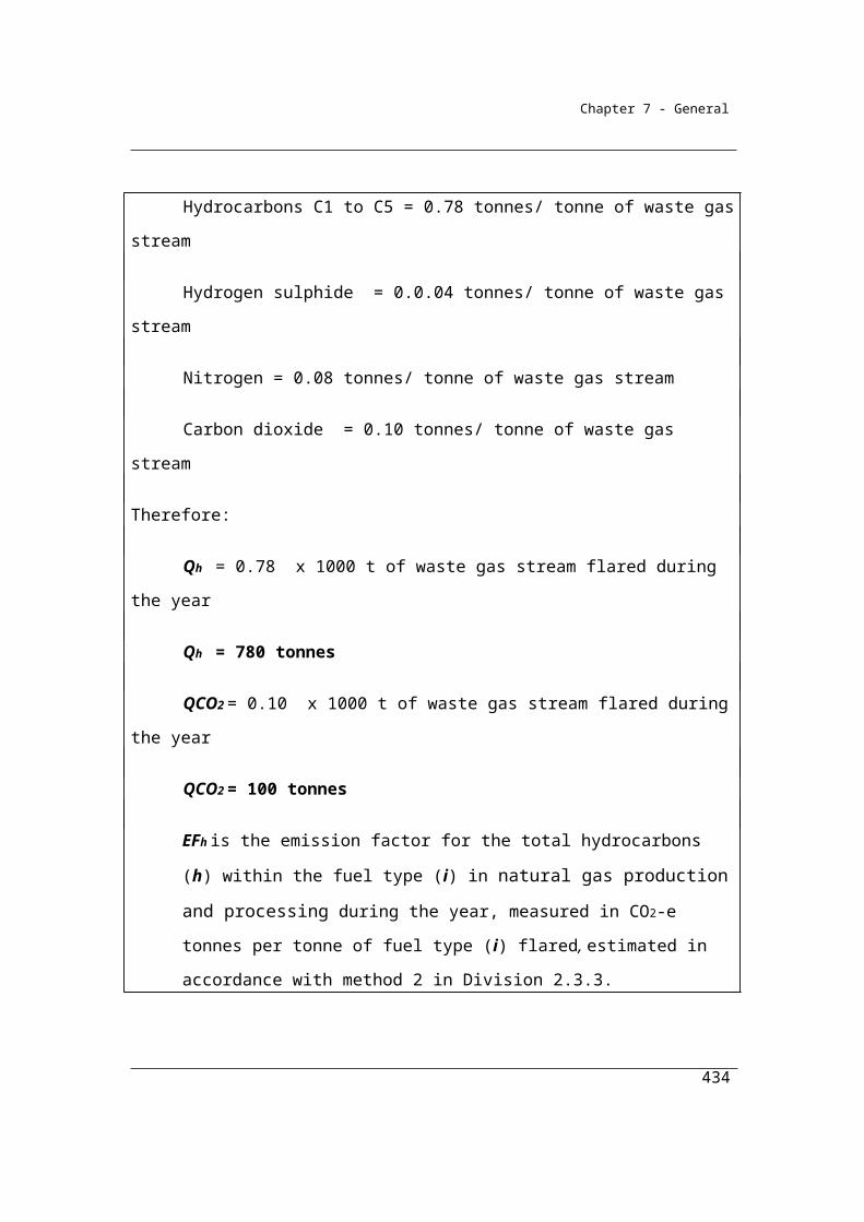
Chapter 7 - General
(v) for estimating the tonnage of the construction and demolition waste stream—using the percentage value specified in columns 2 to 9 of item 3 of the following table for the State or Territory in which the landfill is located.
Waste streams and estimation of tonnageItem
Col. 1 Col. 2
Col. 3
Col. 4
Col. 5
Col. 6
Col. 7 Col. 8
Col. 9
Waste stream NSW%
VIC%
QLD%
WA%
SA%
TAS%
ACT%
NT%
1 Municipal solid waste
31 36 43 26 36 57 43 43
2 Commercial and industrial
42 24 14 17 19 33 42 14
3 Construction and demolition
27 40 43 57 45 10 15 43
(3) For paragraph 5.9(2)(a), if the landfill is permitted to receive only:(a) non-putrescible waste; or(b) commercial and industrial waste and construction and demolition
waste;the waste may be assumed to consist of only commercial and industrial waste and construction and demolition waste.
(4) If subsection (3) applies, the tonnage of each waste stream mentioned in column 1 of the following table must be estimated:
(a) if the operator of the landfill is required, under a law of the State or Territory in which the landfill is located, to collect data on tonnage of waste received at the landfill according to the waste streams set out in column 1—by using that data; or
(b) if paragraph (a) does not apply and the operator of the landfill is able to estimate, in accordance with one of the criteria set out in section 5.5, the tonnage of the waste streams set out in column 1—by using that data; or
(c) if paragraphs (a) and (b) do not apply—by using the percentage values in columns 2 to 9 for the State or Territory in which the landfill is located for each waste stream in column 1.
434

Chapter 7 - General
Waste streams and estimation of tonnageItem Col. 1 Col.
2Col.
3Col.
4Col.
5Col.
6Col. 7 Col.
8Col.
9Waste stream NSW
%VIC
%QLD
%WA
%SA%
TAS%
ACT%
NT%
1 Commercial and industrial waste
61 38 25 23 30 77 74 25
2 Construction and demolition waste
39 62 75 77 70 23 26 75
(5) If subsection (3) applies and the landfill is permitted to receive only one of the waste streams set out in column 1 of the table in subsection (4), that waste stream will be taken to constitute the total waste received.
5.10A Homogenous waste streams
Homogenous waste streams have been introduced to cover situations where a
landfill receives discrete deliveries of waste of a homogenous composition during the
year. Homogenous waste streams allow a landfill operator to undertake stream-
specific sampling and analysis for waste loads of single origin together with default
compositions for waste loads of dispersed origin.
For the shredder flock waste stream, it is a requirement that the composition of this
stream be determined according to the sampling and analysis requirements set out in
section 5.11 (2). For alternative waste treatment residues where it is not possible to
determine the stream composition, a default DOC and DOCf values and decay rate
constants are provided.
(1) For paragraph 5.9(1)(b), the homogenous waste streams have the characteristics mentioned in subsection (2) and are as follows:
(a) alternative waste treatment residues;(b) shredder flock;(c) inert waste.
(2) Homogenous waste streams have the following characteristics:(a) they are from a single known and verifiable origin, as evidenced by
invoices or, if delivery does not involve a commercial transaction, other delivery documentation;
435
Chapter 7 - General
(b) they are not extracted from a general waste stream;(c) they do not undergo compositional change between generation and
delivery to a landfill;(d) they are delivered in loads containing only the waste mentioned in
paragraph (1)(a), (b) or (c).
(3) For paragraph 5.9(2)(b), the tonnage of each homogenous waste stream mentioned in subsection (1) must be estimated:
(a) by using the amount of homogenous waste received at the landfill during the year as evidenced by invoices; or
(b) if the amount of homogenous waste received at the landfill during the year is measured in accordance with State or Territory legislation applying to the landfill—by using that measurement; or
(c) by using direct measurement of quantities of homogenous waste received at the landfill during the year using measuring equipment calibrated to a measurement requirement; or
(d) in accordance with industry estimation practices (such as the use of accepted industry weighbridges, receipts, invoices, other documents or records or population and per-capita waste generation rates).
Note: Waste accepted in the landfill from the year of opening of the landfill that meets
the criteria of a homogenous waste stream must be treated as a homogenous waste
stream for the purpose of calculating the opening stock of degradable organic carbon
at the beginning of the reporting year for all waste mix types.
It is intended that the requirements of 5.10A(2) restrict the use of homogenous
waste streams to the following very specific circumstances:
Waste has been generated by a single plant or activity. For example,
shredder flock delivered to landfill cannot come from multiple recycling plants
in a single load. Each plant’s waste must be treated individually;
only those homogenous waste streams identified are being generated at the
waste generating activity;
there must be no pre-sorting of general waste streams in order to derive
homogenous waste streams. For example, where a construction activity has
generated general construction and demolition waste, it is not possible to
extract the inert component of the general stream prior to disposal and class it
436

Chapter 7 - General
as homogenous inert waste while maintaining the default composition for the
residual construction and demolition stream;
Landfill operators should maintain records to justify the waste streams classifications
adopted for the purposes of NGER reporting.
5.11 Waste mix types
(1) For subsection 5.9(3), the waste mix types are as follows:(a) food;(b) paper and cardboard;(c) textiles;(d) garden and park;(e) wood and wood waste;(f) sludge;(g) nappies;(h) rubber and leather;(i) inert waste.
(2) The percentage of the total waste tonnage for each waste mix type mentioned in column 1 of an item in the following table must be estimated by using:
(a) sampling techniques specified in:(i) waste audit guidelines issued by the State or Territory in which
the landfill is located; or(ii) if no guidelines have been issued by the State or Territory in
which the landfill is located—ASTM D 5231–92 (Reapproved 2008) or an equivalent Australian or international standard; or
(b) the tonnage of each waste mix type received at the landfill estimated in accordance with the criteria set out in section 5.5; or
(c) subject to subsection 5.11(3), the default waste stream percentages in columns 2, 3, 4 and 5 for the item for each waste mix type.
Default waste stream percentage for waste mix typeItem Column 1 Column 2 Column 3 Column 4 Column 5
Waste mix type
Municipal solid waste class I default (%)
Municipal solid waste class II default (%)
Commercial and industrial waste default (%)
Construction and demolition waste default (%)
1 Food 35 40.3 21.5 0
437
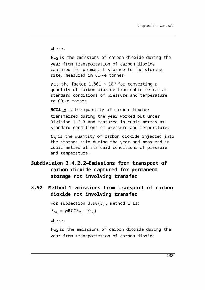
Chapter 7 - General
Default waste stream percentage for waste mix typeItem Column 1 Column 2 Column 3 Column 4 Column 5
Waste mix type
Municipal solid waste class I default (%)
Municipal solid waste class II default (%)
Commercial and industrial waste default (%)
Construction and demolition waste default (%)
2 Paper and cardboard
13 15.0 15.5 3
3 Garden and park
16.5 3.9 4 2
4 Wood and wood waste
1 1.2 12.5 6
5 Textiles 1.5 1.7 4 06 Sludge 0 0 1.5 07 Nappies 4 4.6 0 08 Rubber and
leather1 1.2 3.5 0
9 Inert waste 28 32.2 37.5 89
(3) If the licence or other authorisation authorising the operation of the landfill restricts the waste mix types (restricted waste mix type) that may be received at the landfill, the percentage of the total waste volume for each waste mix type mentioned in column 1 of an item of the following table (appearing immediately before the example) must be estimated:
(a) for a restricted waste mix type—by using the maximum permitted tonnage of the restricted waste mix type received at the landfill, as a percentage of the total waste received at the landfill; and
(b) for each waste mix type that is not a restricted waste mix type (unrestricted waste mix type)—by adjusting the default percentages in columns 2, 3, 4 and 5 of the following table for the item for each unrestricted waste mix type, in accordance with the following formula:
mtu
mtr mtrmax mtumtuadj
mtu
W +W W W
W = W
where:
Wmtuadj is the adjusted percentage for each unrestricted waste mix type.
Wmtu is the default percentage for each unrestricted waste mix type in columns 2, 3, 4 and 5 of the table appearing immediately before the example.
438
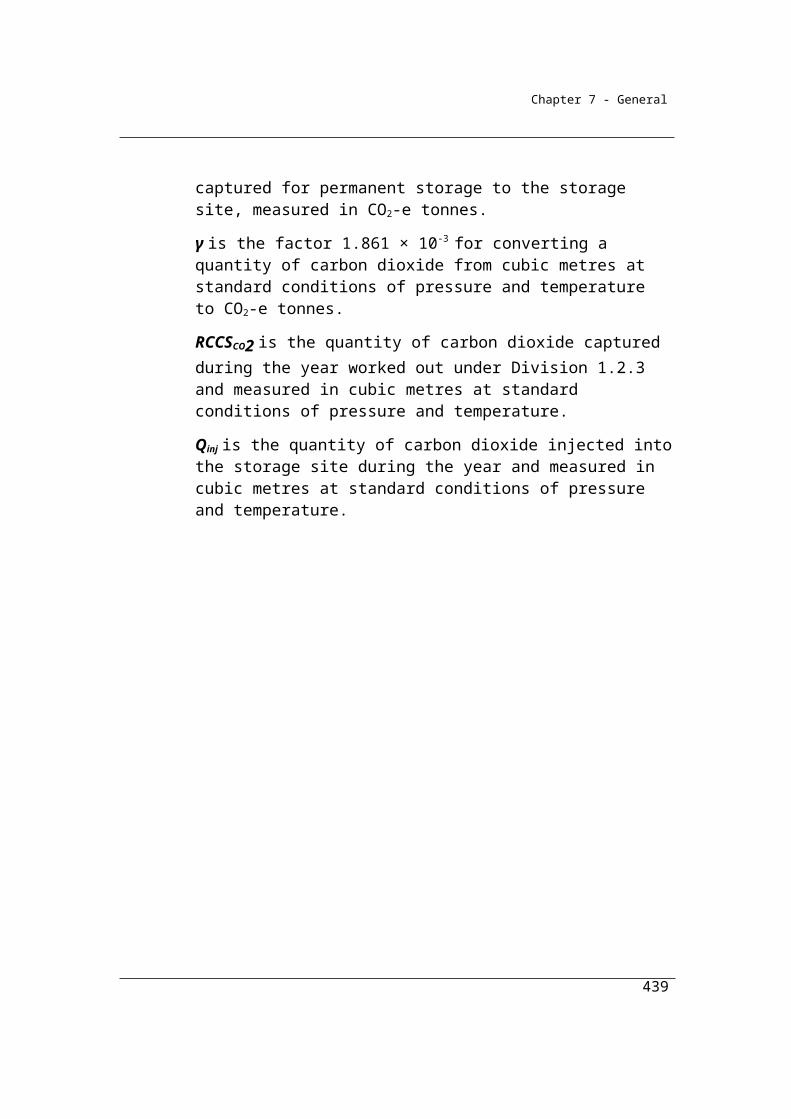
Chapter 7 - General
Wmtr is the default percentage for each restricted waste mix type in columns 2, 3, 4 and 5 of the table appearing immediately before the example.
Wmtrmax is the maximum percentage for each restricted waste mix type.
∑ means sum the results for each unrestricted waste mix type.
Default waste stream percentage for waste mix typeItem Column 1 Column 2 Column 3 Column 4 Column 5
Waste mix type
Municipal solid waste class I default (%)
Municipal solid waste class II default (%)
Commercial and industrial waste default (%)
Construction and demolition waste default (%)
1 Food 35 40.3 21.5 02 Paper and
cardboard13 15.0 15.5 3
3 Garden and park
16.5 3.9 4 2
4 Wood and wood waste
1 1.2 12.5 6
5 Textiles 1.5 1.7 4 06 Sludge 0 0 1.5 07 Nappies 4 4.6 0 08 Rubber and
leather1 1.2 3.5 0
9 Inert waste 28 32.2 37.5 89
Example:
A landfill in a State is licensed only to receive commercial and industrial waste. A condition of the licence is that the landfill is restricted to receiving no more than 5% (Wmtrmax = 5%) food waste in its deliveries. The landfill operator accounts for this restriction by using the formula for each unrestricted waste type (Wmtu) in the table above. So, for paper and paper board waste, the calculation is:
mtuadj
21.5 W = 15.5 +
15.5 + 4 + 12.5 + 4 + 1.5 + 3.5 + 37.5 = 18.8
The operator would continue to use the formula for each unrestricted waste mix type. For the restricted waste mix type the percentage used is Wmtrmax.
The following table sets out all the relevant variables and results for this example.
439

Chapter 7 - General
Item Waste mix type Wmtu
(%)Wmtr
(%)Wmtrmax
(%)Wmtadj
(%)1 Food 21.5 5.0
2 Paper and cardboard 15.5 18.8
3 Garden and park 4.0 4.8
4 Wood and wood waste 12.5 15.1
5 Textiles 4.0 4.8
6 Sludge 1.5 1.8
7 Nappies 0.0 0.0
8 Rubber and leather 3.5 4.2
9 Inert waste 37.5 45.4
5.11A Certain waste to be deducted from waste received at landfill when estimating waste disposed in landfill
(1) When estimating the tonnage of waste by waste mix type disposed of in a landfill, the tonnage of the following waste is to be deducted from the estimates of waste received at the landfill:
(a) waste that is taken from the landfill for recycling or biological treatment;
(b) waste that is received at the landfill for recycling or biological treatment at the landfill site;
(c) waste that is used at the landfill for construction purposes, daily cover purposes, intermediate cover purposes or final capping and cover purposes.
(2) If the waste to be deducted under subsection (1) is a general waste stream mentioned in subsection 5.10(1), the tonnage of the waste to be deducted may be estimated by using the default waste stream percentages mentioned in subsection 5.11(2) for each waste mix type.
5.12 Degradable organic carbon content
For paragraph 5.4A(c), the amount of the degradable organic carbon content of the solid waste at the landfill must be estimated by using the
440
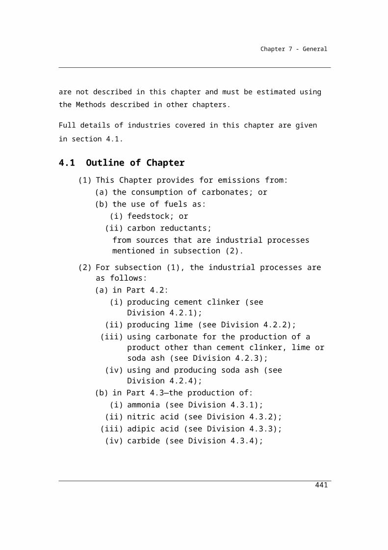
Chapter 7 - General
degradable organic carbon values in column 3 of an item in the following table for each waste mix type in column 2 for that item.
Item Waste mix type Degradable organic carbon value
1 Food 0.152 Paper and cardboard 0.403 Garden and green 0.204 Wood 0.435 Textiles 0.246 Sludge 0.057 Nappies 0.248 Rubber and Leather 0.399 Inert waste 0.0010 Alternative waste
treatment residues0.08
5.13 Opening stock of degradable organic carbon for the first reporting period
The calculation of the opening stock of carbon in a landfill in any given year requires
historical data on quantities and composition of waste sent to landfill in all prior years
of the landfill’s operation. These data may not be available in all instances. Section
5.13 sets out the methods that can be applied in determining the opening stock of
carbon.
(1) For paragraph 5.4A(d), the amount of opening stock of degradable organic carbon at the landfill at the start of the first reporting period for the landfill must be estimated in accordance with subsection 5.4(5):
(a) by using the details of the total tonnage of solid waste (broken down into waste stream and waste mix type and estimated in accordance with section 5.5) disposed of in the landfill each year over the lifetime of the landfill until the start of the first reporting period for the landfill; or
(b) if the operator of a landfill is unable to comply with paragraph (a)—by using the following information in relation to the landfill:(i) the number of years that the landfill has been in operation;
441
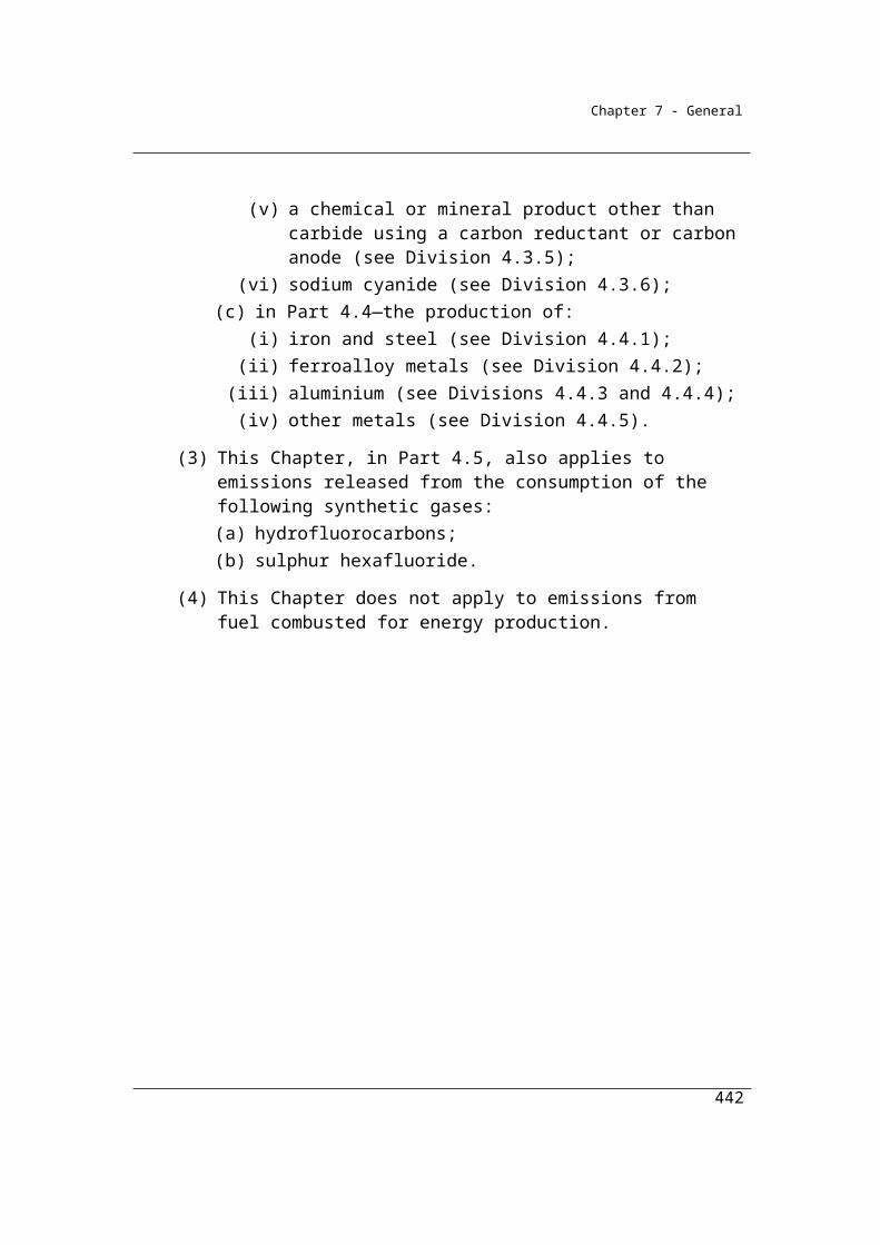
Chapter 7 - General
(ii) the estimated annual tonnage of solid waste disposed of in the landfill over the lifetime of the landfill until the start of the first reporting period for the landfill, worked out in accordance with subsection (2);
(iii) the State or Territory in which the landfill is located.
(2) For subparagraph (1)(b)(ii), the estimated annual tonnage of waste is to be worked out:
(a) by using the average annual tonnage of solid waste disposed of in the landfill for the years for which data is available; or
(b) by conducting a volumetric survey of the landfill in accordance with subsections (3) and (4); or
(c) by using industry estimation practices (such as the use of accepted industry weighbridges, receipts, invoices, other documents or records or population and per-capita waste generation rates).
(3) For paragraph (2)(b), the survey:(a) must be a ground-based survey or an aerial survey; and(b) must be conducted by a qualified surveyor.
(4) For the volumetric survey, the volume of waste is to be converted to mass by using one of the following volume-to-mass conversion factors:
(a) the landfill volume-to-mass conversion factors that were used during the most recent reporting year in order to comply with a landfill reporting requirement of the State or Territory in which the landfill is located;
(b) if the factors mentioned in paragraph (a) were not used during the most recent reporting year in order to comply with a landfill reporting requirement of the State or Territory in which the landfill is located—the volume-to-mass conversion factors specified in column 3 of an item in the following table for a waste stream specified in column 2 of the item.
Item Waste stream Volume-to-mass conversion factor
1 Municipal solid waste 1.1 tonnes per cubic metre2 Commercial and industrial waste 1.1 tonnes per cubic metre3 Construction and demolition
waste1.1 tonnes per cubic metre
442
Chapter 7 - General
5.14 Methane generation constants—(k values)
Landfill operators have two options for the selection of k values under method 1. The first option is to select k values based upon the state or territory in which the landfill is located. The second option is to select k values based upon the climatic conditions (mean annual temperature, precipitation and evaporation) at or near the landfill site.
Under option 2, mean annual temperature can be calculated from data available on the Bureau of Meteorology website (http://www.bom.gov.au/climate/data/). The BOM provide data on mean maximum and mean minimum temperatures over the entire time-series of weather station data. Mean annual temperature is calculated as the arithmetic average of the mean maximum and mean minimum temperature.
Mean annual precipitation is available directly from the BOM weather station data. No additional calculations are required in order to derive this value.
Where BOM records are missing data for any of the previous 10 years, landfill operators may use average values to fill in data gaps in order to undertake the required calculations.
Landfills in the “temperate” classifications will also need an estimate of mean annual evaporation. Mean annual evaporation data are available from certain BOM weather stations. Under the provisions of section 5.14, mean annual evaporation data should be obtained from the closest weather station to the landfill for which evaporation records exist. Reporters should consult the BOM on obtaining the appropriate evaporation records required for the selection of climate-based k values.
(1) This section is made for paragraph 5.4A(e).
(2) Before selecting methane generation constants (k values) from the table in subsection (6), the landfill operator must:
(a) obtain records of each of the following for the 10 year period ending immediately prior to the reporting year for which the landfill operator selects k values:(i) mean annual evaporation;
(ii) mean annual precipitation;(iii) mean annual temperature; and
(b) based on those records, identify, for the landfill facility, the landfill classification mentioned in column 2 of the table.
443
Chapter 7 - General
Note: See subsection (6) for definitions related to the requirements in paragraphs (2)(a) and (b).
(3) A landfill operator must select k values from either:(a) the table in subsection (5); or(b) the table in subsection (6).
(4) If a landfill operator selects k values from the table in subsection (6) in a reporting year, the landfill operator must select k values from that table in each subsequent reporting year.
(5) The k values for solid waste at a landfill in a State or Territory mentioned in column 2 of an item in the following table are the constants set out in column 4 for a waste mix type mentioned in column 3 for the item.
k values for Solid Waste at a LandfillItem State or Territory Waste mix type k values1 NSW Food
Paper and cardboardGarden and GreenWoodTextilesSludgeNappiesRubber and LeatherAlternative waste treatment residue
0.1850.060.100.030.060.1850.060.060.06
2 VIC, WA, SA, TAS, ACT FoodPaper and cardboardGarden and GreenWoodTextilesSludgeNappiesRubber and LeatherAlternative waste treatment residue
0.060.040.050.020.040.060.040.040.04
3 QLD, NT FoodPaper and cardboardGarden and Green
0.40.070.17
444

Chapter 7 - General
k values for Solid Waste at a LandfillItem State or Territory Waste mix type k values
WoodTextilesSludgeNappiesRubber and LeatherAlternative waste treatment residue
0.0350.070.40.070.070.07
(6) The k values for solid waste at a landfill with a landfill classification mentioned in column 2 of an item in the following table are the constants set out in column 4 for a waste mix type mentioned in column 3 for the item.
k values for Solid Waste at a LandfillItem Landfill
classificationWaste mix type k values
1 Temperate dry FoodPaper and cardboardGarden and GreenWoodTextilesSludgeNappiesRubber and LeatherAlternative waste treatment residue
0.060.040.050.020.040.060.040.040.04
2 Temperate wet FoodPaper and cardboardGarden and GreenWoodTextilesSludgeNappiesRubber and LeatherAlternative waste treatment residue
0.1850.060.100.030.060.1850.060.060.06
3 Tropical dry FoodPaper and cardboard
0.0850.045
445
Chapter 7 - General
k values for Solid Waste at a LandfillItem Landfill
classificationWaste mix type k values
Garden and GreenWoodTextilesSludgeNappiesRubber and LeatherAlternative waste treatment residue
0.0650.0250.0450.0850.0450.0450.045
4 Tropical wet FoodPaper and cardboardGarden and GreenWoodTextilesSludgeNappiesRubber and LeatherAlternative waste treatment residue
0.40.070.170.0350.070.40.070.070.07
(7) In this section:
Bureau of Meteorology Guideline means the document titled Guidelines for the Siting and Exposure of Meteorological Instruments and Observing Facilities (Observation Specification No. 2013.1), published by the Bureau of Meteorology in January 1997.Note: The Bureau of Meteorology Guideline is available at www.bom.gov.au.
mean annual evaporation means the mean annual evaporation:(a) recorded at the landfill by a meteorological station that is established
and maintained in accordance with the Bureau of Meteorology Guideline; or
(b) if paragraph (a) does not apply—recorded by a Bureau of Meteorology weather station that:(i) is located nearest to the landfill; and
(ii) records mean annual evaporation.
mean annual precipitation means the mean annual precipitation:(a) recorded at the landfill by a meteorological station that is established
and maintained in accordance with the Bureau of Meteorology Guideline; or
446
Chapter 7 - General
(b) if paragraph (a) does not apply—recorded by a Bureau of Meteorology weather station that:(i) is located nearest to the landfill; and
(ii) records mean annual precipitation.
mean annual temperature means the mean annual temperature:(a) recorded at the landfill by a meteorological station that is established
and maintained in accordance with the Bureau of Meteorology Guideline; or
(b) if paragraph (a) does not apply—recorded by a Bureau of Meteorology weather station that:(i) is located nearest to the landfill; and
(ii) records mean annual temperature.Note: The Bureau of Meteorology weather station directory is available at
www.bom.gov.au.
temperate dry, for a landfill, means that the landfill has:(a) a mean annual temperature that is 20° centigrade or less; and(b) a ratio of mean annual precipitation to mean annual evaporation that
is less than 1.
temperate wet, for a landfill, means that the landfill has:(a) a mean annual temperature that is 20° centigrade or less; and(b) a ratio of mean annual precipitation to mean annual evaporation that
is greater than 1.
tropical dry, for a landfill, means that the landfill has:(a) a mean annual temperature that is greater than 20° centigrade; and(b) a mean annual precipitation that is less than 1 000 mm.
tropical wet, for a landfill, means that the landfill has:(a) a mean annual temperature that is greater than 20° centigrade; and(b) a mean annual precipitation that is 1 000 mm or more.
5.14A Fraction of degradable organic carbon dissimilated (DOCF)
For paragraph 5.4A(f), the fraction of organic carbon dissimilated (DOCF) for a waste mix type mentioned in column 2 of an item of following the table is the value mentioned in column 3 for the item.
447
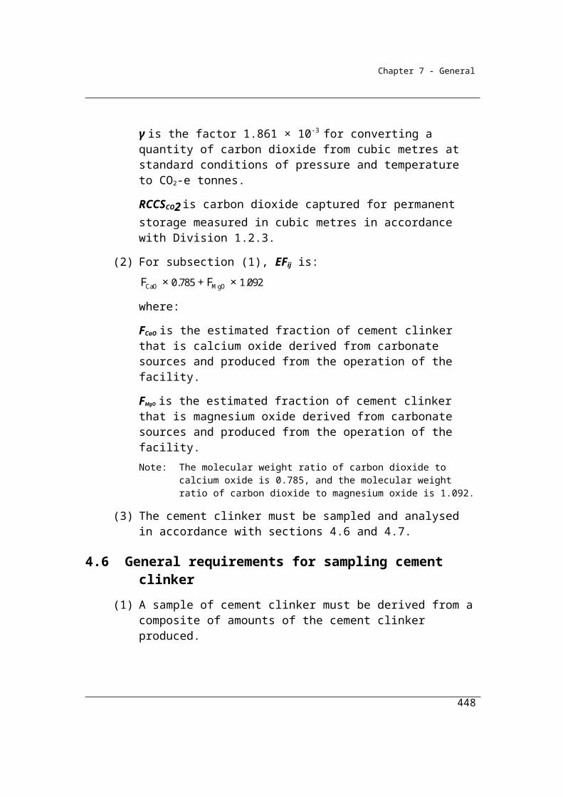
Chapter 7 - General
Item Waste mix type DOCF value
1 Food 0.842 Paper and cardboard 0.493 Garden and green 0.474 Wood 0.235 Textiles 0.506 Sludge 0.507 Nappies 0.508 Rubber and leather 0.509 Inert waste 0.0010 Alternative waste treatment residues 0.50
Example: Calculation of emissions from solid waste disposal
A facility constituted by a managed landfill accepting municipal solid waste uses
the IPCC FOD model to determine that the emissions (CH4 gen) from the facility are
28,493 tonnes of CO2-e during the year. Additionally 1,000,000 m3 of methane has
been captured at the facility (Qcap) during the year for combustion. On this basis
γ(Qcap + Qflared + Qtr)/CH4 gen is assessed to be 50% therefore according to section
5.4 – subsection 2 of the Determination, CH4* is taken to equal CH4 gen.
The reporter elects to use Method 1 (5.2.2 in the National Greenhouse and Energy
Reporting (Measurement) Determination 2008) for methane released from
landfills. Emissions are estimated as follows:
where:
Ej is emissions of methane (CO2-e) released by the landfill during the year.
CH4 * is the estimated quantity of methane in landfill gas generated by the landfill during the year.
γ is the factor 6.784 x 10-4 x 25 converting cubic metres to CO2-e tonnes.
Qcap is the quantity of methane in landfill gas captured for combustion from the landfill during the
year and measured in cubic metres.
448
Ej = (CH4 * – γ(Qcap + Qflared + Qtr)) x (1-OF)
Chapter 7 - General
Qflared is the quantity of methane in landfill gas flared from the landfill during the year and measured
in cubic metres.
Qtr is the quantity of methane in landfill gas transferred out of the landfill during the year and
measured in cubic metres.
OF is the oxidation factor (0.1) for near-surface methane in the landfill.
Therefore, to calculate emissions of methane in CO2 e tonnes :
Total methane generated during the year as estimated using the FOD model =
28,493 tonnes CO2-e
Ej = (CH4* – γ(Qcap + Qflared + Qtr)) x (1-OF)
= (28,493 - 6.784x10-4 x 25 x (1,000,000 + 0 + 0)) x (1-0.1)
Total emissions of methane = 13,229 t CO2-e
5.14B Methane correction factor (MCF) for aerobic decomposition
For paragraph 5.4A(g), the methane correction factor for aerobic decomposition is 1.
5.14C Fraction by volume generated in landfill gas that is methane (F)
For paragraph 5.4A(h), the fraction by volume of methane generated in landfill gas is 0.5.
5.14D Number of months before methane generation at landfill commences
For paragraph 5.4A(i), the number of months that have ended before methane generation at the landfill commences is 6.Note: To calculate the value of M, add 7 to the number of months mentioned in
section 5.14D. Using the number of months mentioned in section 5.14D, the calculation would be 6 plus 7 and the value of M would be 13.
449
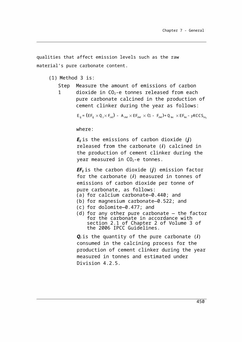
Chapter 7 - General
Division 5.2.3—Method 2—emissions of methane released from landfills
Subdivision 5.2.3.1—methane released from landfills
5.15 Method 2—methane released by landfill (other than from flaring of methane)
Section 5.15 sets out Method 2, which is based on the method published in the IPCC 2000 Good Practice Guidance and Uncertainty Management in National Greenhouse Gas Inventories.
(1) For subparagraph 5.3(1)(a)(ii), method 2 is that the following calculations must be performed:
(a) calculate the amount of methane emissions released by the landfill during the reporting year, measured in CO2-e tonnes, using the following equation:
Ej = ∑z Ejz; and
(b) calculate the amount of emissions of methane released by the landfill from a sub-facility zone during the reporting year, measured in CO2-e tonnes, using the following equation:
Ejz = [CH4genz – γ(Qcapz+ Qflaredz + Qtrz)] (1 − OF)
where:
Ej is the emissions of methane released by the landfill during the reporting year, measured in CO2-e tonnes.
Ejz is the emissions of methane released by the landfill from a sub-facility zone during the reporting year, measured in CO2-e tonnes.
CH4genz is the estimated quantity of methane in landfill gas generated by the landfill from a sub-facility zone during the reporting year, worked out in accordance with subsection (2), measured in CO2-e tonnes.
γ is the factor 6.784 10-4 25 converting cubic metres of methane at standard conditions measured to CO2-e tonnes.
Qcapz is the quantity of methane in landfill gas captured for combustion by the landfill from a sub-facility zone during the reporting year, measured in cubic metres in accordance with Division 2.3.6.
450
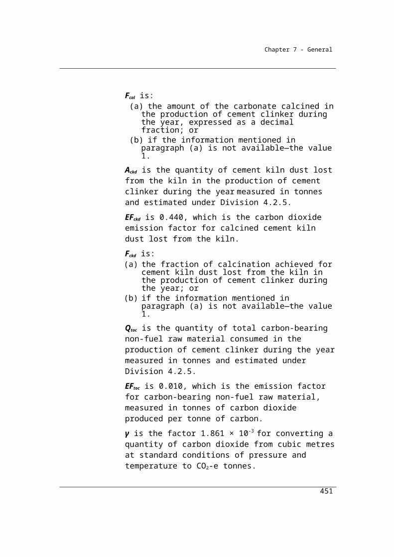
Chapter 7 - General
Qflaredz is the quantity of methane in landfill gas flared by the landfill from a sub-facility zone during the reporting year, measured in cubic metres in accordance with Division 2.3.6.
Qtrz is the quantity of methane in landfill gas transferred out of the landfill from a sub-facility zone during the reporting year, measured in cubic metres in accordance with Division 2.3.6.
OF is the oxidation factor (0.1) for near surface methane in the landfill.
∑z is sum for all sub-facility zones.
(2) For paragraph (1)(b), CH4genz for each sub-facility zone must be worked out:
(a) using the estimates mentioned in section 5.4A and the equations mentioned in sections 5.4B, 5.4C and 5.4D; and
(b) for each waste mix type mentioned in column 3 of the table in subsection 5.14(6)—using the method for working out the methane generation constant and the formula for calculating the adjusted methane generation constant mentioned in section 5.17L.
(3) For subsection (1), for a landfill, if:
4gen
(Q + Q + Q )CH
cap trflared
is less than or equal to the collection efficiency amount for the landfill calculated in accordance with section 5.15C, then:
*
4 4genCH = CH
where:
Qcap is the quantity of methane in landfill gas captured for combustion from the landfill during the year, measured in cubic metres in accordance with Division 2.3.6.
Qflared is the quantity of methane in landfill gas flared from the landfill during the year, measured in cubic metres in accordance with Division 2.3.6.
Qtr is the quantity of methane in landfill gas transferred out of the landfill during the year, measured in cubic metres in accordance with Division 2.3.6.
451

Chapter 7 - General
CH4* is the estimated quantity of methane in landfill gas generated by the landfill during the year, measured in CO2-e tonnes.
CH4gen is the quantity of methane in landfill gas generation released from the landfill during the year estimated in accordance with subsection 5.4(5) and measured in CO2-e tonnes.
(4) For subsection (1), if:
is more than the collection efficiency amount for the landfill calculated in accordance with section 5.15C, then:
where:
γ is the factor 6.784 10-4 25 converting cubic metres of methane at standard conditions measured to CO2-e tonnes.
CEA is the collection efficiency amount for the landfill calculated in accordance with section 5.15C.
CH4*
z is the estimated quantity of methane in landfill gas generated by the sub-facility zone during the year, measured in CO2-e tonnes.
CH4gen is the quantity of methane in landfill gas generation released from the landfill during the year, estimated in accordance with subsection 5.4(5) and measured in CO2-e tonnes.
Qcap is the quantity of methane in landfill gas captured for combustion from the landfill during the year, measured in cubic metres in accordance with Division 2.3.6.
Qcapz is the quantity of methane in landfill gas captured for combustion by the landfill from a sub-facility zone during the reporting year, measured in cubic metres in accordance with Division 2.3.6.
Qflared is the quantity of methane in landfill gas flared from the landfill during the year, measured in cubic metres in accordance with Division 2.3.6.
452

Chapter 7 - General
Qflaredz is the quantity of methane in landfill gas flared by the landfill from a sub-facility zone during the reporting year, measured in cubic metres in accordance with Division 2.3.6.
Qtr is the quantity of methane in landfill gas transferred out of the landfill during the year, measured in cubic metres in accordance with Division 2.3.6.
Qtrz is the quantity of methane in landfill gas transferred out of the landfill from a sub-facility zone during the reporting year, measured in cubic metres in accordance with Division 2.3.6.
(5) For subsection (1), if the result of the first equation in subsection (4) is, for the reporting year for which the result is calculated (the current reporting year), greater than the collection efficiency amount for the landfill calculated in accordance with section 5.15C:
(a) the change in the quantity of the opening stock of decomposable degradable organic carbon (∆Cost) must be calculated using the equation mentioned in section 5.15A; and
(b) the quantity of the closing stock of decomposable degradable organic carbon (∆Ccst) must be calculated using the equation mentioned in section 5.15B.
(6) This method may be used only if specific information is available on the waste mix types at the landfill.Note 1: For the definition of reporting year, see the National Greenhouse and Energy
Reporting Regulations 2008.
Note 2: For provisions regarding the selection and requirements of representative zones, see sections 5.16 to 5.17I.
Note 3: Section 5.17AA sets out, for a landfill operator using method 2 in Division 5.2.3 or method 3 in Division 5.2.4, the number of sub-facility zones that the landfill operator may select and the requirements for sub-facility zones that the landfill operator must comply with.
5.15A Equation—change in quantity of particular opening stock at landfill for calculating CH4gen
(1) For paragraph 5.15(5)(a), this section applies if the result of the first equation in subsection 5.15(4) is, for the reporting year for which the result is calculated (the current reporting year), greater than the collection efficiency amount for the landfill calculated in accordance with section 5.15C.
453

Chapter 7 - General
(2) The change in the quantity of the opening stock of decomposable degradable organic carbon (∆Cost) that is:
(a) located in the landfill during the reporting year; and(b) measured in tonnes; and(c) lost through decomposition;
must be calculated using the equation mentioned in subsection (3).
(3) For subsection (2), the equation is:
where:
t is the reporting year.
F is the fraction of methane generated in landfill gas estimated in accordance with section 5.14C.Note 1: For the definition of reporting year, see the National Greenhouse and Energy
Reporting Regulations 2008.
Note 2: If the result of the first equation in subsection 5.15(4):(a) was, for a previous reporting year or years, greater than the collection
efficiency amount for the landfill calculated in accordance with section 5.15C; and
(b) is, for the current reporting year, less than or equal to the collection efficiency amount for the landfill calculated in accordance with section 5.15C;
use:(c) the calculation in section 5.15A to calculate the change in the opening
stock of carbon for the final reporting year in which the result of that equation is greater than the collection efficiency amount for the landfill calculated in accordance with section 5.15C; and
(d) the calculation in section 5.15B to calculate the closing stock for that reporting year.
5.15B Equation—quantity of closing stock at landfill in particular reporting year
(1) For paragraph 5.15(5)(b), this section applies if the result of the first equation in subsection 5.15(4) is, for the reporting year for which the result is calculated (the current reporting year), greater than the collection efficiency amount for the landfill calculated in accordance with section 5.15C.
(2) The quantity of closing stock of decomposable degradable organic carbon (Ccst) in the most recent year to which subsection 5.15(4) applies:
454
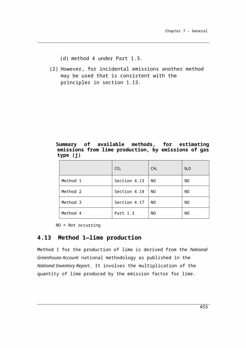
Chapter 7 - General
(a) located in the landfill during the reporting year; and(b) measured in tonnes;
must be calculated using the equation mentioned in subsection (3).
(3) For subsection (2), the equation is:
ostcst ostC = C C
where:
Ccst is the closing stock of carbon in the last year in which subsection 5.15(4) was used to calculate emissions.
Cost is the opening stock of carbon in the first year in which 5.15(4) was used to calculate emissions.
∆Cost is the change in carbon stock for all years in which 5.15(4) applies and is estimated in accordance with 5.15ANote: The quantity of closing stock calculated in accordance with this section is the
same as the quantity of opening stock for the current reporting year.
5.15C Equation—collection efficiency limit at landfill in particular reporting year
The revised method for determining landfill gas collection efficiency under method 2 is based on the US EPA Mandatory Reporting of Greenhouse Gases final rule (FR Vol 74/ No. 209) which provides for the application of collection efficiency limits exceeding 85% under specific operational circumstances.
The Mandatory Reporting Rule sets out a calculation that must be undertaken to determine a whole of landfill collection efficiency. The calculation involves the delineation of landfill area by cover type and takes into account system coverage, operation, and cover system materials.
(1) Subject to subsection (2), the collection efficiency limit for a landfill is calculated using the following formula:
where:
A2 is the area of the landfill in square metres, regardless of cover type, without active gas collection.
455
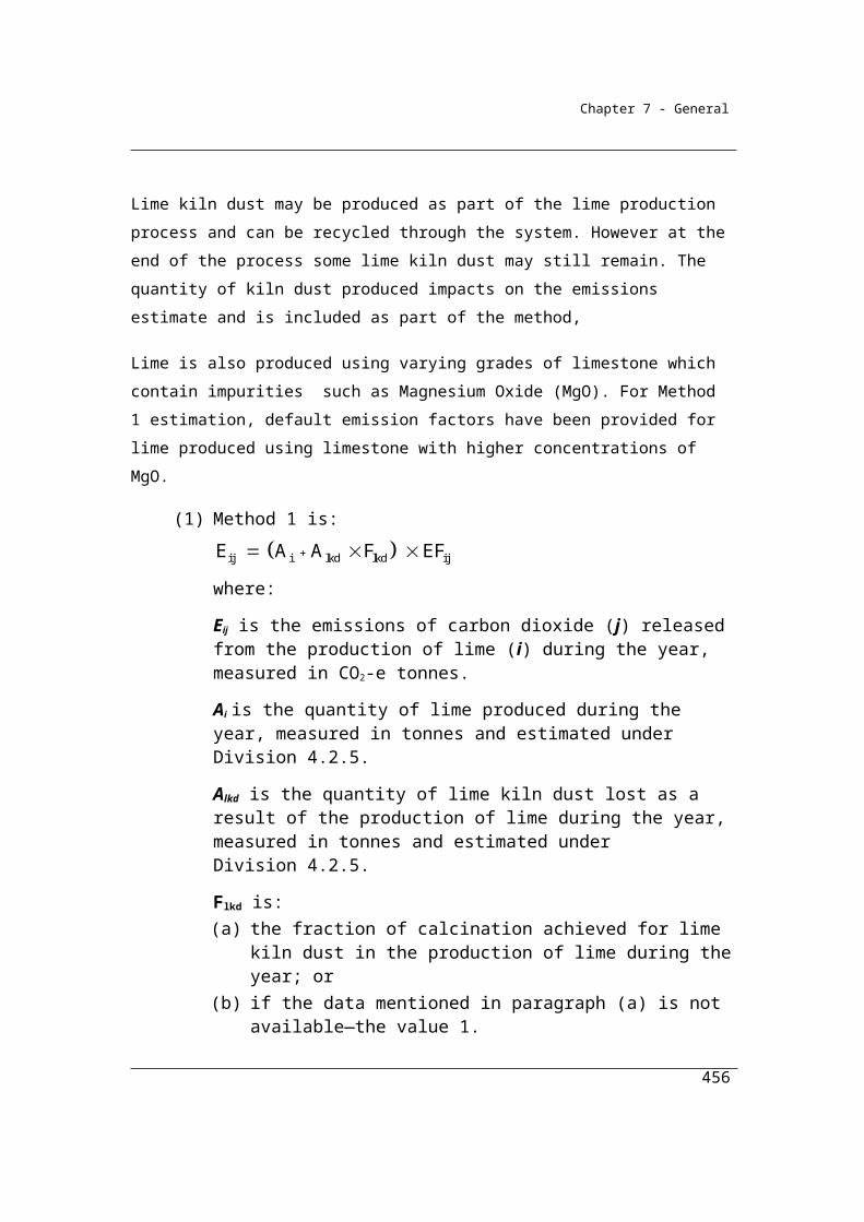
Chapter 7 - General
A3 is the area of the landfill in square metres that has daily soil cover and active gas collection.
A4 is the area of the landfill in square metres that has active gas collection and:
(a) a top cover that is an intermediate type; or(b) a final cover of clay that is less than 1 metre thick; or(c) a phytocap layer that is at least 1 metre thick.
A5 is the area of the landfill in square metres that has active gas collection and:
(a) a final cover of clay that is at least 1 metre thick; or(b) a geo-membrane cover system.
(2) Where a landfill operator is unable to specify the areas for the factors A2, A3, A4 and A5 in subsection (1), the collection efficiency limit for the landfill is calculated using the following formula:
Subdivision 5.2.3.2—Requirements for calculating the methane generation constant (k)
5.16 Procedures for selecting representative zone
The operator of the landfill must select a representative zone in accordance with sections 5.17 to 5.17B for the purpose of estimating the methane generated from the landfill.
5.17 Site plan—preparation and requirements
(1) Before selecting a representative zone, the operator of a landfill must prepare a site plan of the landfill.
(2) The site plan must:(a) be consistent with the provisions relating to landfill site plans
included in the document entitled Technical Guidelines for the estimation of greenhouse gas emissions by facilities in Australia, published by the Department of Climate Change and Energy Efficiency in July 2011; and
(b) if the landfill has more than one sub-facility zone—show the boundaries of each sub-facility zone.
Note: The Technical Guidelines for the estimation of greenhouse gas emissions by facilities in Australia are available at www.environment.gov.au.
456
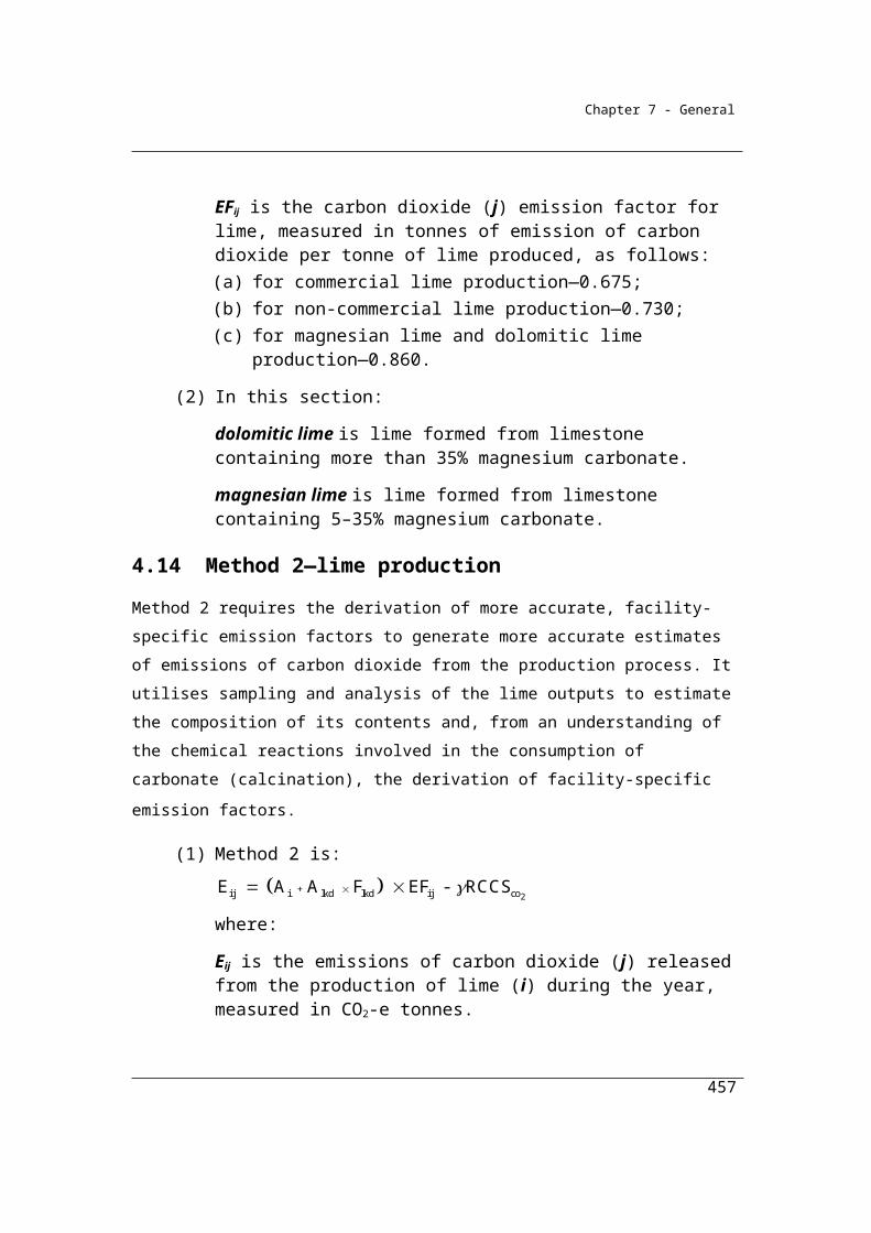
Chapter 7 - General
Technical Guidelines relating to landfill site plans
The operator of the landfill must prepare a site plan prior to the commencement of the use of method 2 that must include the following information:
a.a description of basic site characteristics:
- the planned life of the facility and permitted volumes of waste disposal; the exact boundaries of the waste disposal area;
- containment design (liner and capping);
- fill process (for example, phased or cell; landfill or landraise);
- sideslopes and edges;
- any fissures or weak points in the cap where emissions may be high; and
b.spatial mapping of permanent and temporary capped zones and uncapped zones; and
c.spatial mapping of volumes, mass and age of waste disposed at the facility; and
d.description of gas control systems:
- locations of wells and their capacity and other relevant attributes;
- gas monitoring points;
- density of well sub-systems;
- description of flares (location, timing and gas capacities); and
e.leachate management systems;
- leachate towers, sumps, risers systems (including recirculation)
- leachate monitoring points
- presence of former co-disposal systems (e.g. liquid disposal trenches);
f) the boundaries of all sub-facility and representative zones; and
457
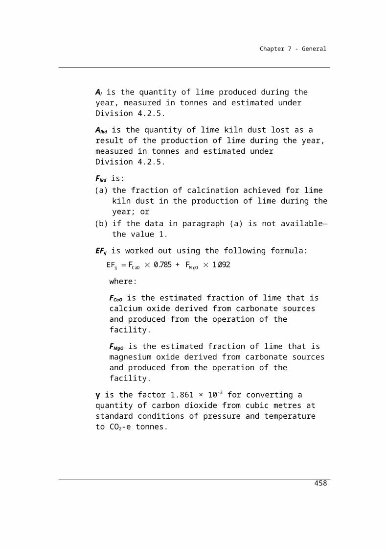
Chapter 7 - General
g) any other features of the facility that could impact on flux box locations or the capacity of a representative zone or to be representative of facility.
5.17AA Sub-facility zones—maximum number and requirements
(1) After preparing a site plan, the landfill operator may select sub-facility zones for the site plan.
(2) The number of sub-facility zones the landfill operator may select:(a) for sub-facility zones that contain only waste mix of the type
mentioned in paragraph 5.11(1)(i)—is unlimited; and(b) for all other sub-facility zones—must not exceed 4.
(3) A sub-facility zone:(a) must cover an area of at least 1 hectare; and(b) must be a single area within the landfill; and(c) must have a uniform composition of waste mix types so that the
estimates of the methane generated by the sub-facility zone are in accordance with section 1.13; and
(d) must not be subject to:(i) landfill gas inflow from another sub-facility zone; or
(ii) landfill gas outflow to another sub-facility zone.
(4) At least one sub-facility zone must contain a representative zone.
5.17A Representative zones—selection and requirements
After preparing a site plan, the operator of the landfill must select a representative zone that:
(a) covers an area of at least one hectare; and(b) is a single area within the sub-facility zone; and(c) has a uniform composition of waste mix types so that the estimates
of the methane generated by the representative zone comply with section 1.13; and
(d) contains a number of operating gas collection wells that is sufficient to enable accurate and representative estimates of the methane being generated by the representative zone to be obtained; and
(e) contains only waste that has been undisturbed:(i) for at least 12 months before any methane generation is
measured in accordance with section 5.17H; or
458

Chapter 7 - General
(ii) if the representative zone is on landfill that recirculates leachate or adds moisture through the waste to promote methane generation—for the period determined by an independent expert; and
(f) has a low permeability basal liner that includes:(i) a compacted clay base; or
(ii) a geomembrane base; or(iii) another demonstrated low permeability base; and
(g) is confined on:(i) 4 sides by low permeability barriers, including:
(A) capped areas; or(B) a landfill cell lining; or(C) if the representative zone does not have a landfill cell
lining—a demonstrated low gas permeability strata; or(ii) 3 sides by low permeability barrier and one side by an active gas
collection system; and(i) includes a gas extraction system that:
(i) forms the boundary of the fourth side; and(ii) extends beyond the boundary of the representative zone; and
(j) has a top cover that is a final type or an intermediate type.
It is common for landfills to practice progressive filling of excavated areas. In this context, the requirements above will dictate how many completed cells are to be included in the representative zone. In the following example, there are 3 completed cells which are capped with active gas collection and a fourth cell which is being filled. The completed cells are sealed on 2 sides by the excavation edge and the third side by a temporary cap (which will subsequently be removed for the filling of future cells). The representative zone in this situation is indicated by the red box in the following diagram. The requirement of being confined on 3 sides by low permeability barriers and the fourth side by an active gas collection system restricts the selection of the representative zone to cells 1 and 2 (subject to the other requirements for representative zones).
459
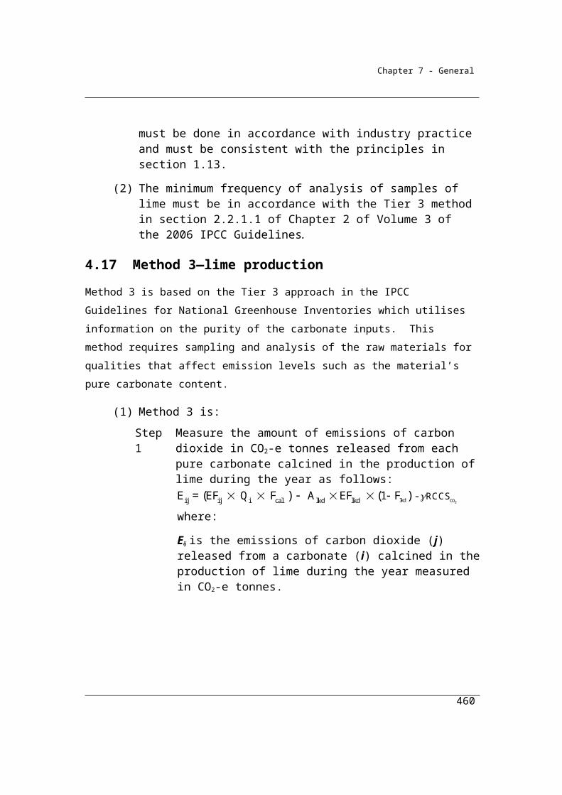
Chapter 7 - General
460

Chapter 7 - General
5.17B Independent verification
(1) After the operator of the landfill has selected a representative zone for a sub-facility zone, the operator of the landfill must arrange for an independent expert to certify, in writing, that:
(a) the boundaries of the representative zone are appropriate for the purpose of obtaining accurate and representative estimates of the methane being generated by the representative zone; and
(b) the representative zone is representative of the sub-facility zone.
(2) The independent expert must also prepare a written report for the zone.
(3) The report must include the details specified in the technical guidelines in relation to expert reports.
Expert reports on representative zones
The operator of the facility must enter into a written agreement with the expert, which may be by an exchange of letters, specifying the terms governing the preparation of a report providing an assessment on the selection of the representative zone.
The written report must contain all information which the operator and others likely to rely on the report would reasonably require, and reasonably expect to find in the report, for the purpose of making an informed decision about the representativeness of the selected zone.
The report should include:
(a) a description of the relevant aspects of the facility;
(b) an account of the material history of the facility, including the volume, mass, age and types of waste in the representative zone;
(c) an assessment as to the degree of uniformity of moisture levels between the representative zone and the remainder of the landfill, taking into account the technologies and processes used in the representative zone that affect moisture levels compared with other parts of the facility including the use of leachate recirculation and cell size; and
461
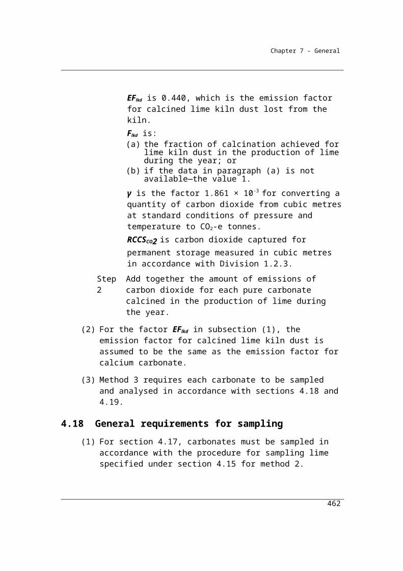
Chapter 7 - General
(d) an assessment of the degree of uniformity of the depth of waste, taking into account the results of volumetric surveys conducted for the site, if any have been conducted.
The independent expert must also provide an assessment as to whether the boundaries of the representative zone are appropriate. The boundaries of the zone should define the volume of waste that is generating the gas captured by the collection system within the representative zone.
For any given point on the boundary, the location of the boundary should be located by determining a distance between two adjacent wells - one well internal to the selected area and one well external to the selected area - which is proportional to the relative landfill gas flow rate of each well recorded over the test period. The data used must have been recorded during periods of operation of the collection system that reflect normal operating conditions (i.e. consistent with the operation of the system on days of flux box measurement). There must be no significant net flow of landfill gas across the representative zone boundary when the measurements are made.
For zones with vertical well systems in place, the boundary can be assumed to be a vertical surface extending from the landfill surface to the base of the waste.
For zones with horizontal well systems in place the representative zone may be estimated on the zone of influence of the horizontal well system.
Detailed technical information and data should be included in the report if their understanding is important to the assessment. Explanations of unusual or new technical processes and activities that may be material to the understanding of the assessment should be included, where commercial confidentiality considerations allow.
Experts must not rely uncritically on the data and other information provided, either by the operator of the facility or obtained otherwise. They must undertake suitable checks, enquiries, analyses and verification procedures to establish reasonable grounds for establishing the soundness of the contents and conclusions of the report.
The expert must either certify that the representative zone has been selected in accordance with these Guidelines and the National Greenhouse and Energy
462
Chapter 7 - General
Reporting (Measurement) Amendment Determination 2012, or the contrary, and personally sign the report.
5.17C Estimation of waste and degradable organic content in representative zone
The amount of waste, and the amount of degradable organic content in the waste, disposed of in the representative zone must be estimated in accordance with sections 5.5 to 5.12 for each reporting year that waste is disposed of in the representative zone.
5.17D Estimation of gas collected at the representative zone
(1) The operator of the landfill must estimate the total amount, and concentration, of landfill gas measured in tonnes of methane per year collected by all of the landfill gas collection wells located within the representative zone.
(2) Measurement of the landfill gas flow rate for each well must be undertaken in accordance with Division 2.3.6.
(3) The methane concentration of the landfill gas from the representative zone:
(a) may be estimated from measurements of landfill gas obtained at each gas collection well located within the representative zone using industry standard landfill gas analysers that are calibrated to the manufacturer’s specifications; or
(b) may be assumed to be the methane concentration for the landfill as analysed under Subdivision 2.3.3.2.
(4) Data about the methane gas flow rates at each well in the representative zone must be:
(a) the data used for operational purposes; and(b) recorded at least once a month for a period of at least 12 months.
(5) Fuel flow meter equipment and gas composition monitoring equipment used to measure and analyse the landfill gas must be calibrated in accordance with:
(a) a standard specified in section 2.24 or an equivalent standard; or (b) the calibration procedures specified, and at the frequencies
recommended, by the manufacturer of the equipment.
463
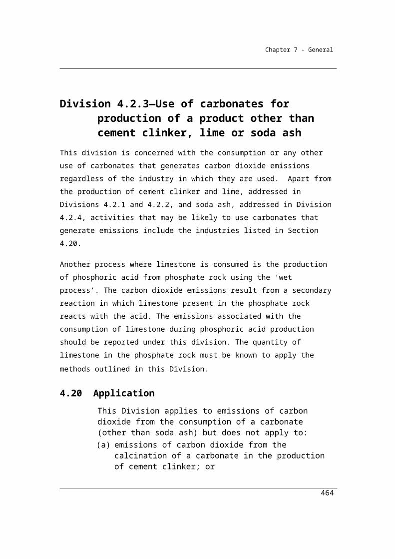
Chapter 7 - General
(6) Fuel flow meter equipment and gas composition monitoring equipment must be recalibrated:
(a) at the frequency specified by the manufacturer of the equipment; or(b) if the manufacturer does not specify a recalibration period for the
equipment—annually.
(7) Estimates of gas flow must be converted from cubic metres to mass by using the formula in subsection 1.21(1).
5.17E Estimating methane generated but not collected in the representative zone
(1) The operator must estimate the amount of emissions of methane in the representative zone that is not collected by the collection wells in the zone.
(2) Estimates must be obtained by using the procedures in sections 5.17F to 5.17H.
5.17F Walkover survey
(1) The operator of the landfill must arrange for an independent expert to conduct, at least every 3 months, a walkover survey of the representative zone using a portable gas measurement device in order to:
(a) determine the near surface gas concentrations in the representative zone and in the immediately surrounding area; and
(b) identify locations within the representative zone that have:(i) low methane emissions; and
(ii) intermediate methane emissions; and(iii) elevated methane emissions; and(iv) high methane emissions; and
(c) scan the representative zone by scanning along multiple transects that are less than 25 metres wide; and
(d) if the scan detects an area within the representative zone that has high methane emissions—scan along multiple transects 1 metre wide; and
(e) record the results; and(f) map the results against the site plan prepared in accordance with
section 5.17.
(2) The portable gas measurement device must be capable of detecting hydrocarbons at 10 parts per million.
464
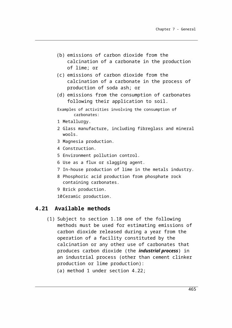
Chapter 7 - General
(3) In this section:
low methane emissions means methane emissions that the results of a scan performed in accordance with this section indicate are equal to or less than 50 parts per million.
intermediate methane emissions means emissions that the results of a scan performed in accordance with this section indicate are greater than 50 parts per million and equal to or less than 100 parts per million.
elevated methane emissions means methane emissions that the results of a scan performed in accordance with this section indicate are greater than 100 parts per million and less than 500 parts per million.
high methane emissions means methane emissions that the results of a scan performed in accordance with this section indicate are equal to or greater than 500 parts per million.
5.17G Installation of flux boxes in representative zone
(1) After the walkover survey has been completed, the operator of the landfill must arrange for the installation of flux boxes in the representative zone.
(2) The number of flux boxes must be at least the minimum number identified during the walkover survey.
(3) The flux boxes must be installed at the locations identified in the walkover survey.
(4) If the operator installs the flux boxes, the operator must ensure that an independent expert certifies, in writing, that the boxes have been correctly installed and located.
(5) If the operator arranges for some other person to install the flux boxes, the other person must be an independent expert.
(6) If an independent expert identifies an area within a representative zone that has low methane emissions, the landfill operator must:
(a) calculate the methane gas flow rate of the area by using a rate of 0.01g CH4 per square metre per hour; or
(b) take all reasonable steps to ensure that the independent expert performs the calculation mentioned in paragraph (a).
(7) If an independent expert identifies an area within a representative zone that has intermediate methane emissions, the landfill operator must:
465
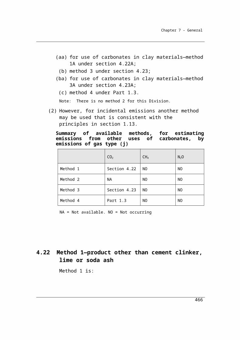
Chapter 7 - General
(a) calculate the methane gas flow rate of the area by using a rate of 0.12g CH4 per square metre per hour; or
(b) take all reasonable steps to ensure that the independent expert performs the calculation mentioned in paragraph (a).
(8) If an independent expert identifies an area within a representative zone that has elevated methane emissions, the landfill operator must:
(a) calculate the methane gas flow rate for the area by using a rate of 4.3 g CH4 per square metre per hour; or
(b) take all reasonable steps to ensure that the independent expert performs the calculation mentioned in paragraph (a); or
(c) take all reasonable steps to ensure that the independent expert works out the minimum number of flux boxes for the area by using the following formula:
2 + 0.15 Z
where:
Z is the size of the area within the representative zone that has elevated methane emissions, measured in square metres.
(9) If an independent expert identifies an area within a representative zone that has high methane emissions, the landfill operator must:
(a) calculate the methane gas flow rate of the area by using a rate of 75 g CH4 per square metre per hour; or
(b) take all reasonable steps to ensure that the independent expert performs the calculation mentioned in paragraph (a); or
(c) take all reasonable steps to ensure that the independent expert works out the minimum number of flux boxes for the area by using the following formula:
2 + 0.15 Z
where:
Z is the size of the area within the representative zone that has high methane emissions, measured in square metres.
(10) In this section:
low methane emissions means methane emissions that the results of a scan performed in accordance with this section indicate are equal to or less than 50 parts per million.
466

Chapter 7 - General
intermediate methane emissions means emissions that the results of a scan performed in accordance with this section indicate are greater than 50 parts per million and equal to or less than 100 parts per million.
elevated methane emissions means methane emissions that the results of a scan performed in accordance with this section indicate are greater than 100 parts per million and less than 500 parts per million.
high methane emissions means methane emissions that the results of a scan performed in accordance with this section indicate are equal to or greater than 500 parts per million.
5.17H Flux box measurements
(1) After the flux boxes have been installed in the representative zone, the operator must:
(a) measure the flow of methane in each flux box and arrange for an independent expert to certify, in writing, that the measurements are accurate and were correctly measured; or
(b) arrange for an independent expert to take the measurements.Note: AS/NZS 4323.4—2009 and the publication entitled Guidance on monitoring
landfill gas surface emissions published by the Environment Agency of the United Kingdom in September 2004 contain guidance on how to take measurements in flux boxes.
Expert reports on emission measurements
The operator of the facility must enter into a written agreement with the expert, which may be by an exchange of letters, specifying the terms governing the preparation of a report on the estimation of emissions from the representative zone.
The written report must contain all information which the operator and others likely to rely on the report would reasonably require, and reasonably expect to find in the report, for the purpose of making an informed decision about the estimated emissions from the representative zone. The report must include:
(a) sufficient information about the method(s) used to conduct the walkover and flux box surveys so that another expert could understand the procedures used and analyses undertaken. This information must include:
467
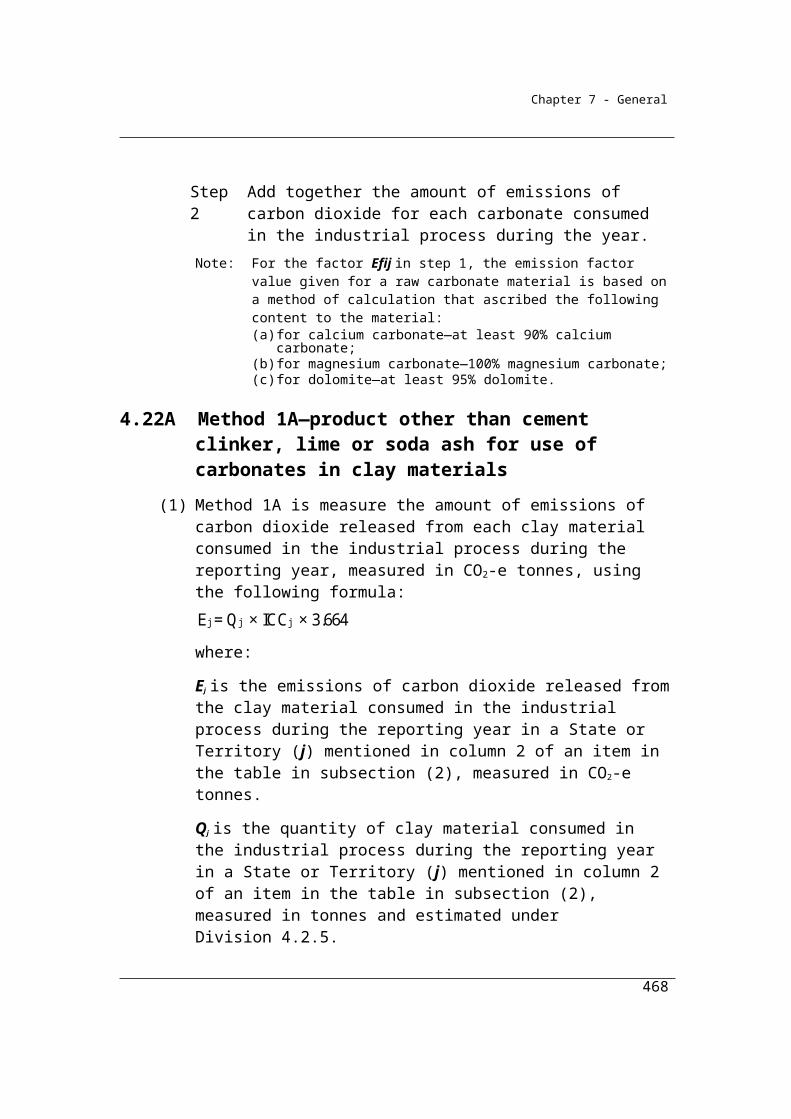
Chapter 7 - General
- a description of the precise boundaries of the representative zone,
and of any recalculations to the estimated boundaries made by the
expert for the conduct of the flux box test;
- a description of the facility and any features which may have affected
placement of flux boxes;
- dates and times at which measurements were undertaken;
- details about the precise location of flux boxes operated for the
measurement process and any relevant information that may have
affected the placement of the flux boxes;
(b) sufficient information about the results obtained so that another expert could understand the procedures used and replicate the estimates. This information must include:
- data on all measurements undertaken, and methods used to determine a gas flow rate estimate at individual flux boxes; and
- details of the geospatial techniques used and the calculations made to estimate the flow of methane emissions from the representative zone from the measurements taken at individual flux boxes.
(c) a qualitative assessment of the accuracy of the measurements obtained. This assessment must take account of relevant conditions that may have affected the measurements taken. The report must include data on:
- rainfall;
- barometric pressure;
- wind speed; and
- temperature;
468
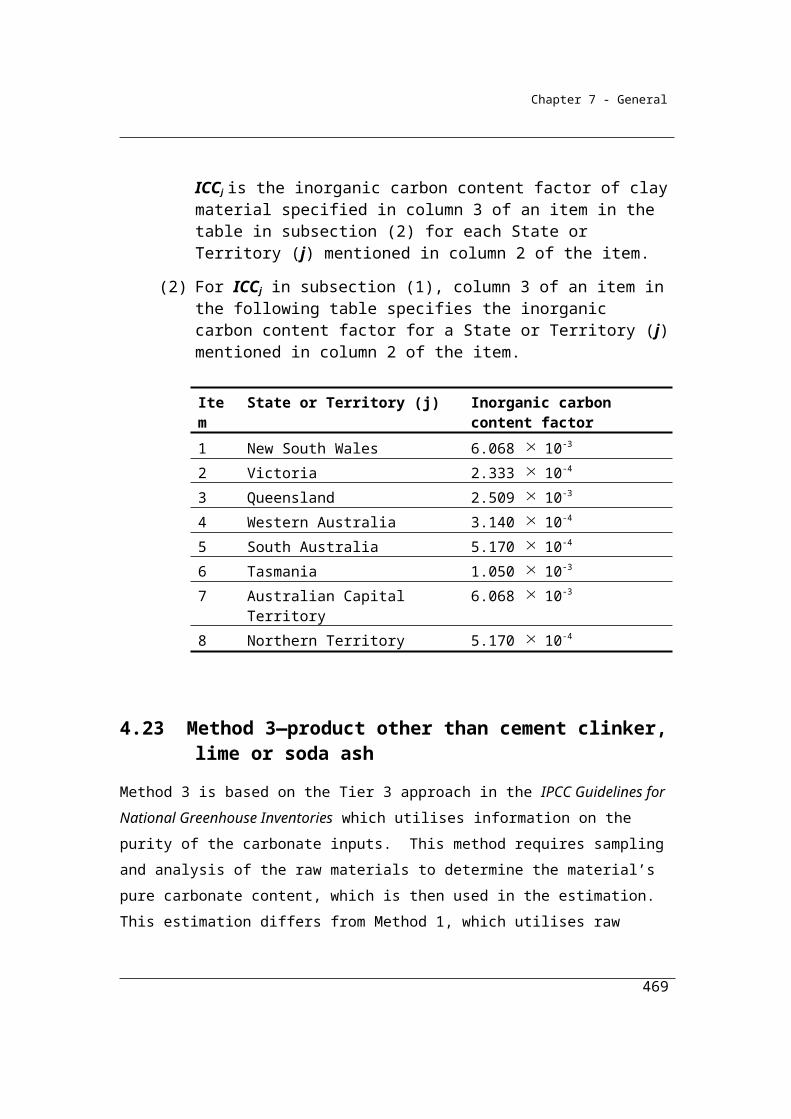
Chapter 7 - General
at the facility or as otherwise specified for the duration of the measurement period. All relevant data for the immediate period prior to the measurements being undertaken, as considered appropriate by the expert, must also be recorded.
(d) a review of any other matters that are material to the report;
(e) information regarding all sources of data used;
(f) a concise summary setting out the key data and important assumptions made and the conclusions drawn by the expert.
Detailed technical information and data should be included in the report if their understanding is important to the assessment. Explanations of unusual or new technical processes and activities that may be material to the understanding of the assessment should be included, where commercial confidentiality considerations allow.
Experts must not rely uncritically on the data and other information provided, either by the operator of the facility or obtained otherwise. They must undertake suitable checks, enquiries, analyses and verification procedures to establish reasonable grounds for establishing the soundness of the contents and conclusions of the report.
The expert must certify that the estimate of emissions from the representative zone has been prepared in accordance with these Guidelines and with the National Greenhouse and Energy Reporting (Measurement) Amendment Determination 2009 and personally sign the report.
(2) The flow of methane from each flux box must be calculated in accordance with the following formula:
dcV dtQ =
A
where:
Q is the flow density of the gas in the flux box, measured in milligrams of methane per square metre per second.
469
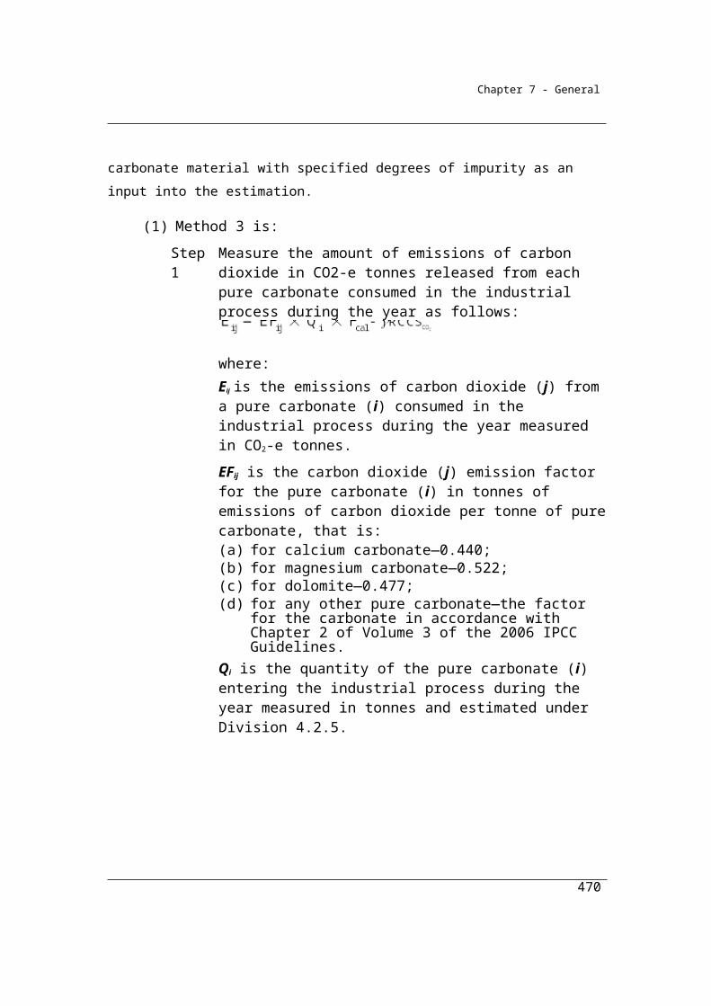
Chapter 7 - General
V is the volume of the flux box, measured in cubic metres.
dcdt
is the rate of change of gas concentration in the flux boxes over time, measured in milligrams per cubic metre per second.
A is the area covered by the flux box, measured in square metres.
(3) The total gas flow rate for the representative zone is to be obtained by using geospatial interpolation techniques.
(4) The amount of methane generated, but not collected, in the representative zone must be estimated by dividing the total gas flow rate obtained in accordance with subsection (3) by:
1 F
where:OF is the oxidation factor mentioned in subsection 5.15(1).
(5) The measurement of methane obtained under the formula in subsection (2) must be converted from milligrams of methane per square metre per second to tonnes of methane for the surface area of the representative zone for the reporting year.
(6) Estimates of gas flow must be converted from cubic metres to mass by using the formula in subsection 1.21(1).
5.17I When flux box measurements must be taken
(1) Flux box measurements must be taken during the normal operating times of the gas collection wells in the representative zone.
(2) The measurements must be completed within 3 days.
5.17J Restrictions on taking flux box measurements
(1) Flux box measurements must not be taken:(a) within 2 days of heavy rainfall over the representative area; or(b) if barometric pressure at the landfill site is rising or falling sharply;
or(c) during frost conditions; or(d) in any other meteorological conditions that may significantly affect
the accuracy of the measurements; or(e) in areas where there is standing water.
Note: AS/NZS 4323.4—2009 and the publication entitled Guidance on monitoring landfill gas surface emissions published by the Environment Agency of the
470
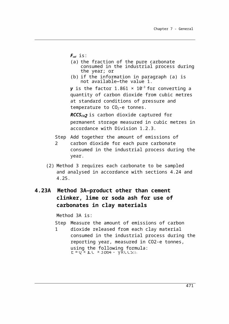
Chapter 7 - General
United Kingdom in September 2004 contain guidance on good measurement practice.
(2) For subsection (1), there is heavy rainfall over a representative area on any day of a month if the amount of rain that is recorded:
(a) at the landfill on that day; or(b) if rainfall is not recorded at the landfill—at the nearest Bureau of
Meteorology weather station to the landfill on that day;exceeds the heavy rainfall benchmark, as calculated in accordance with the following formula:
RFHRF = 2 MRD
where:
HRF is the heavy rainfall benchmark.
RF is the mean monthly rainfall for the month at the landfill or nearest Bureau of Meteorology weather station.
MRD is the mean rainfall days for the month at the nearest Bureau of Meteorology weather station as recorded in the publication published by the Bureau of Meteorology and known as Climate statistics for Australian locations.
5.17K Frequency of measurement
The measurement of emissions by flux boxes must be undertaken on a quarterly basis for a period of at least 12 months.
The 12 month flux-box measurement period should be the same 12 month period in which the measurements of landfill gas collection in the well system are undertaken.
5.17L Calculating the methane generation constant (ki) for certain waste mix types
(1) In this section:
ki means the methane generation constant for each waste mix type:(a) mentioned in column 3 of the table in subsection 5.14(6); and(b) worked out by performing the steps set out in subsection (2).
Qz means the gas flow rate for the representative zone.
471

Chapter 7 - General
CH4gen is the quantity of methane generated by the landfill as calculated under this section and measured in CO2-e tonnes.
(2) For subsection (1), the steps are.Step 1 Identify the total amount of methane:
(a) estimated in accordance with section 5.17D; and(b) collected at the gas collection wells in the representative
zone.Step 2 Identify the total amount of methane generated by the
representative zone:(a) measured in accordance with section 5.17H; and(b) converted in accordance with subsection 5.17H(5).
Step 3 Identify Qz by adding the amount identified under step 1 to the amount identified under step 2.
Step 4 Calculate CH4gen to within ± 0.001 of Qz, using the amount identified under step 3 and the equation mentioned in section 5.4D, by adjusting incrementally each default methane generation constant for each of those waste mix types using the following formula:
kiadj = kidef (1 + incr%)
where:kiadj is the adjusted methane generation constant for each waste mix type mentioned in column 3 of the table in subsection 5.14(6).kidef is the default methane generation constant for each waste mix type mentioned in column 3 of the table in subsection 5.14(6).incr% is the incremental percentage (≤ 1%).
(3) For subsection (1):(a) CH4gen for each representative zone must be worked out:
(i) using the estimates mentioned in section 5.4A and the equations mentioned in sections 5.4B, 5.4C and 5.4D; and
(ii) for each waste mix type mentioned in column 3 of the table in subsection 5.14(6)—using the formula for calculating kiadj and the method of working out ki in this section; and
(b) it is sufficient if CH4gen is within ± 0.001 of Qz.
(4) Subsection (6) applies if:(a) in the previous reporting year, a methane generation constant for
each waste mix type mentioned in column 3 of a table in section 5.14 is selected from one of those tables for the purpose of estimating
472
Chapter 7 - General
methane emissions from the solid waste located in a sub-facility zone; and
(b) ki is worked out before 1 October 2013 for each waste mix type mentioned in column 3 of the table in subsection 5.14(6).
(5) However, subsection (6) does not apply to solid waste of a waste mix type mentioned in column 3 of the table in subsection 5.14(6) if:
(a) the waste has been deposited in a sub-facility zone; and(b) a methane generation constant for the solid waste has been:
(i) estimated under method 2; and(ii) used in the previous reporting year.
(6) For each waste mix type mentioned in column 3 of the table in subsection 5.14(6), ki must be applied in the calculation of methane:
(a) generated from solid waste deposited in a representative zone in a reporting year; and
(b) generated from solid waste deposited in every sub-facility zone in each reporting year for which an independent expert has certified, in accordance with section 5.17B, that the representative zone is representative of the sub-facility zone; and
(c) if the methane is calculated using the estimates mentioned in paragraph 5.14A(a), (b), (c) or (d) and all of the following:(i) the fraction of organic carbon dissimilated mentioned in
column 3 of the table in section 5.14A;(ii) the methane correction factor for aerobic decomposition
mentioned in section 5.14B;(iii) the fraction by volume of methane generated in landfill gas
mentioned in section 5.14C.Note 1: For provisions regarding the selection and requirements of representative
zones, see sections 5.16 to 5.17I.
Note 2: Section 5.17AA sets out, for a landfill operator using method 2 in Division 5.2.3 or method 3 in Division 5.2.4, the number of sub-facility zones that the landfill operator may select and the requirements for sub-facility zones that the landfill operator must comply with.
Notes on resolution of equation in 5.17L
Method 2 rests on the measurement of a flow of methane estimated at a point in time. This flow of methane must reflect the decomposition of an amount of carbon in the wastes deposited in the representative zone.
473
Chapter 7 - General
However, the data on Ca is subject to some uncertainty – more uncertainty than for the measurement of methane generated and, if underestimated, may preclude a solution to the estimation of ‘k’. Consequently, a minimum requirement must be established in relation to Ca to underpin the estimate of ‘k’. That is, the observed amount of methane generated by the landfill must put a floor under the amount of carbon decomposing in the representative zone of the landfill such that:
(1) Ca ≥ Ca~
where Ca~ is the minimum amount of degradable carbon required to solve for ‘k’.
In addition, the non-linear nature of the equation means that it is possible, mathematically, to derive a non-unique solution for the value of ‘k’. Consequently, it is necessary to add an additional constraint to clarify the appropriate approach to the estimation of ‘k’. It is assessed that ‘k’ must occur in the range where, for a given measurement of methane generated in the representative zone, a higher value of Ca results in a lower ‘k’. That is, given that the amount of methane generated is well known, and if it is being derived from what is considered to be a large mass of carbon, then a slower rate of methane flow observed must reflect, all other things being equal, a slower rate of methane generation.
This condition is expressed as:
(2) δk/δCa ≤ 0
where δk is the change in k, and
δCa is the change in Ca in the representative zone
The condition (1) ensures that the solution for ‘k’ occurs in the range where, for a given measurement of methane generated in the representative zone, higher estimated values of Ca result in lower values of ‘k’.
Decay rate constant (k) plotted against the quantity of degradable organic carbon (Ca) for a given flow rate and average age of refuse
474
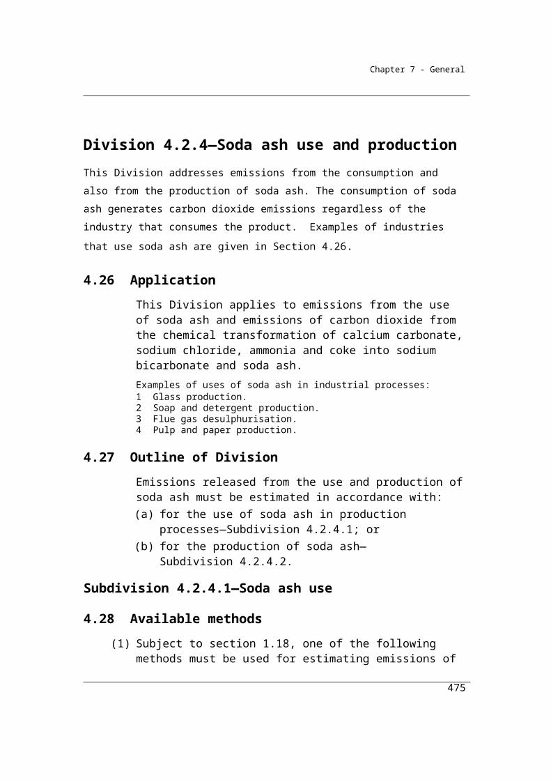
Chapter 7 - General
475
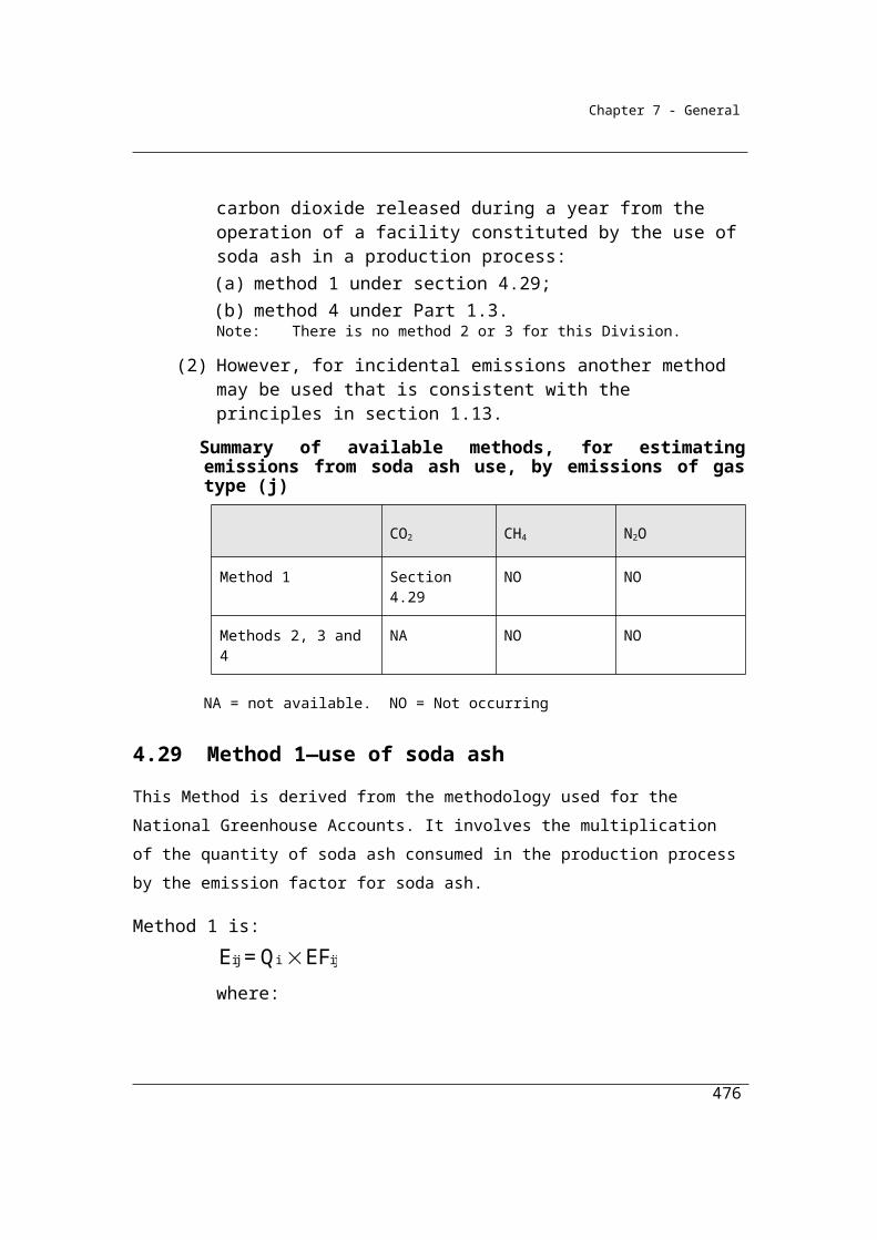
Chapter 7 - General
Division 5.2.4—Method 3—emissions of methane released from solid waste at landfills
5.18 Method 3—methane released from solid waste at landfills (other than from flaring of methane)
Section 5.18 sets out Method 3, which is the same as for Method 2, except that the sampling requirements of the US Environment Protection Agency Method 2E, Determination of landfill gas flow production rates are applied.
(1) For subparagraph 5.3(1)(a)(iii) and subject to subsection (2), method 3 is the same as method 2 under section 5.15.
(2) In applying method 2 under section 5.15, the gas flow rate must be estimated from sampling undertaken during the year in accordance with USEPA Method 2E—Determination of landfill gas production flow rate, as set out in Appendix A-1 of Title 40, Part 60 of the Code of Federal Regulations, United States of America, or an equivalent Australian or international standard.
476

Chapter 7 - General
Division 5.2.5—Solid waste at landfills—Flaring
5.19 Method 1—landfill gas flared
Sections 5.19-5.21 set out Methods 1, 2 and 3 for the flaring of methane in landfill gas. Method 1 is derived from the methods used for the National Greenhouse Accounts. Methods 2 and 3 rely on the sampling and analysis of the fuel to estimate the gas composition of the fuel more closely in order to estimate the quantity of methane flared more accurately.
(1) For subparagraph 5.3(b)(i), method 1 is:
ijj flared flared i
EFE = Q EC
where:
Ej flared is the emissions of gas type (j), being methane and nitrous oxide, released from the landfill from flaring of the methane in landfill gas during the year measured in CO2-e tonnes.
Qflared is the quantity of methane in landfill gas flared during the year measured in cubic metres in accordance with Division 2.3.6.
ECi is the energy content factor of methane in landfill gas in gigajoules per cubic metre (see Schedule 1).
EFij is the relevant emission factor for gas type (j), being methane and nitrous oxide, from the combustion of landfill gas in kilograms of CO2-e per gigajoule (see Schedule 1).
(2) For Qflared in subsection (1), the methane in landfill gas is taken to constitute 50% of the landfill gas.
5.20 Method 2—landfill gas flared
(1) For subparagraph 5.3(1)(b)(ii) and subject to this section, method 2 is the same as method 1 under section 5.19.
(2) In applying method 1 under section 5.19, Qflared must be determined in accordance with the sampling and analysis requirements in Subdivision 2.3.3.2 and the measurement requirements in Division 2.3.6.
477
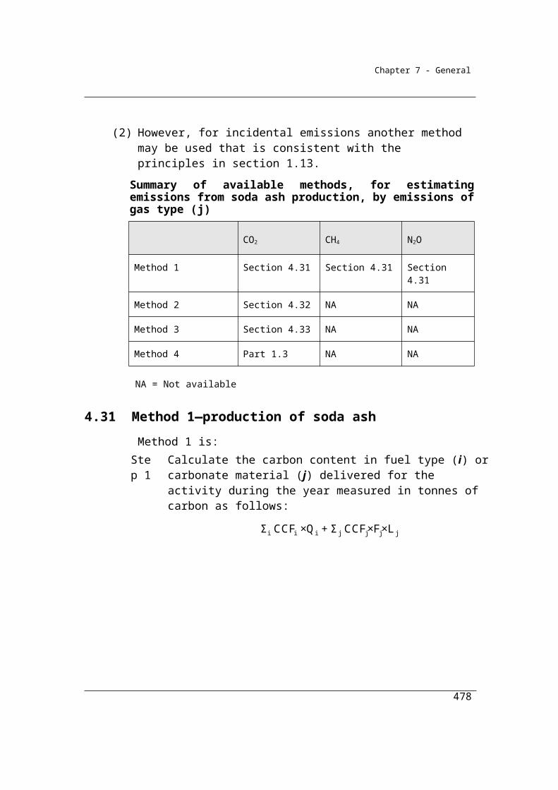
Chapter 7 - General
5.21 Method 3—landfill gas flared
(1) For subparagraph 5.3(1)(b)(iii) and subject to this section, method 3 is the same as method 1 under section 5.19.
(2) In applying method 1 under section 5.19, Qflared must be determined in accordance with the sampling and analysis requirements in Division 2.3.4 and the measurement requirements in Division 2.3.6.
Division 5.2.6—Biological treatment of solid waste
5.22 Method 1—emissions of methane and nitrous oxide from biological treatment of solid waste at a landfill
Section 5.22 sets out Method 1 for emissions released from the Biological treatment of solid waste production. The method to be used is described in IPCC 2006 Guidelines for National Greenhouse Gas Inventories Volume 5, Chapter 4.
(1) For subparagraph 5.3(1)(c)(i) and paragraph 5.3(1)(d), method 1 is:
where:
EFi is the emission factor for each gas type (j), being methane or nitrous oxide, released from the biological treatment type (i) measured in tonnes of CO2-e per tonne of waste processed.
Eij is the emissions of the gas type (j), being methane or nitrous oxide, released from the landfill during the year from the biological treatment type (i) measured in CO2-e tonnes.
Mi is the mass of waste treated by biological treatment type (i) during the year measured in tonnes of waste.
R is:(a) for the gas type methane—the total amount of methane recovered
during the year at the landfill from the biological treatment of solid waste measured in tonnes of CO2-e; or
(b) for the gas type nitrous oxide—zero.
(2) For EFi in subsection (1), the emission factor for each gas type released from the biological treatment type is set out in the following table:
478

Chapter 7 - General
Emission factor for type of gas and biological treatmentItem Biological treatment Emission factor
tonnes CO2-e/tonne of waste treatedMethane Nitrous Oxide
1 Composting at the landfill 0.019 0.0292 Anaerobic digestion at the landfill 0.025 0
5.22AA Method 4—biological treatment of solid waste at the landfill
For subparagraph 5.3(1)(c)(ii), method 4 is as set out in Part 1.3.
479

Chapter 7 - General
Part 5.3—Wastewater handling (domestic and commercial)
Division 5.3.1—Preliminary
5.23 Application
(1) This Part applies to emissions released from the decomposition of organic material, nitrification and denitrification processes, and flaring of sludge biogas, resulting from the handling of domestic or commercial wastewater through:
(a) treatment in wastewater collection and treatment systems; or(b) discharge into surface waters.
(2) In this section, domestic or commercial wastewater means liquid wastes and sludge (including human waste) from housing or commercial premises.
Note: Part 5.3 is intended for use by centralised municipal wastewater treatment
plants. Onsite industrial wastewater treatment is covered under part 5.4.
5.24 Available methods
(1) Subject to section 1.18, for estimating emissions released from the operation of a facility that is constituted by wastewater handling (domestic and commercial) (the plant) during a year:
(a) one of the following methods must be used for emissions of methane from the plant (other than from flaring of methane):(i) method 1 under section 5.25;
(ii) method 2 under section 5.26;(iii) method 3 under section 5.30; and
(b) one of the following methods must be used for emissions of nitrous oxide from the plant (other than from flaring of methane):(i) method 1 under section 5.31;
(ii) method 2 under section 5.32;(iii) method 3 under section 5.36; and
480
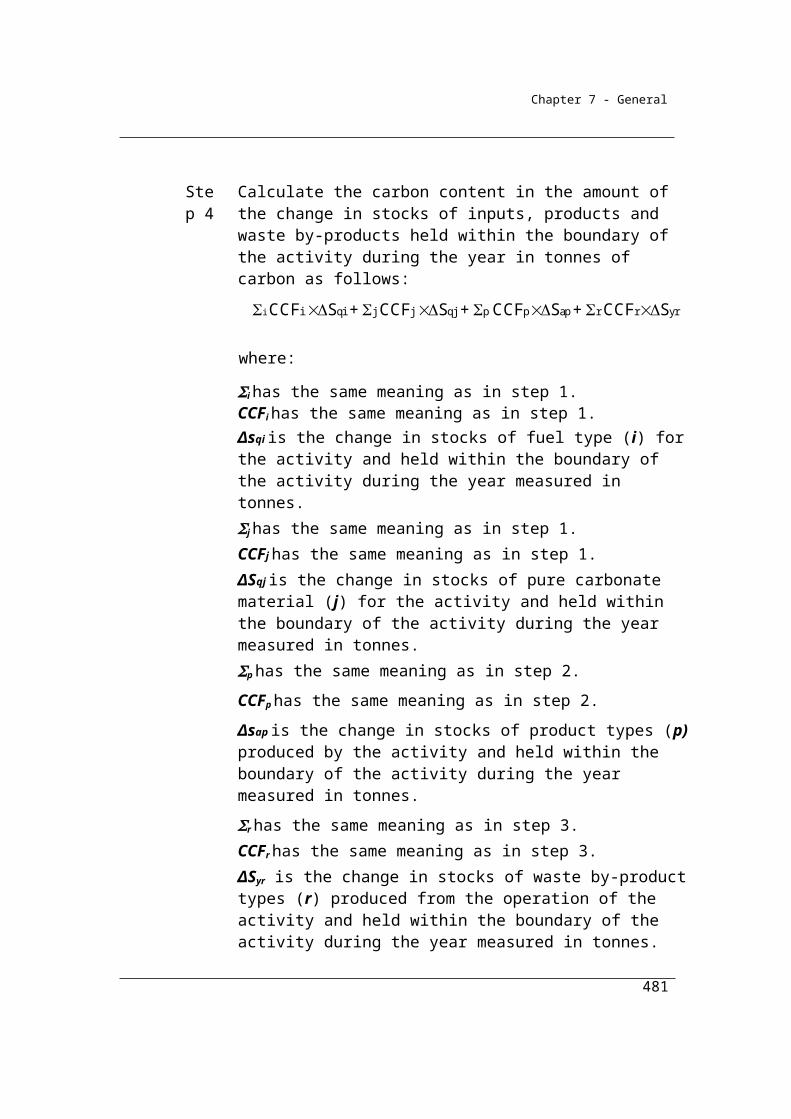
Chapter 7 - General
Summary of available methods by emissions of gas type (j)
CO2 CH4 N2O
Domestic and Commercial waste water management
Method 1 NA Section 5.25 Section 5.31
Method 2 NA Section 5.26 Section 5.32
Method 3 NA Section 5.30 Section 5.36
Method 4 NA NA NA
Methane flared from the operation of the facility
Method 1 NA Section 5.37 Section 5.37
Method 2 NA Section 5.38 Section 5.38
Method 3 NA Section 5.39 Section 5.39
Method 4 NA NA NA
NA = Not available. NO = Not occurring.
(c) one of the following methods must be used for emissions for each gas type as a result of methane flared from the plant:(i) method 1 under section 5.37;
(ii) method 2 under section 5.38;(iii) method 3 under section 5.39.
(2) Under paragraph (1)(c), the same method must be used for estimating emissions of each gas type.
(3) For incidental emissions another method may be used that is consistent with the principles in section 1.13.Note: There is no method 4 for paragraphs (1)(a), (b) and (c).
481
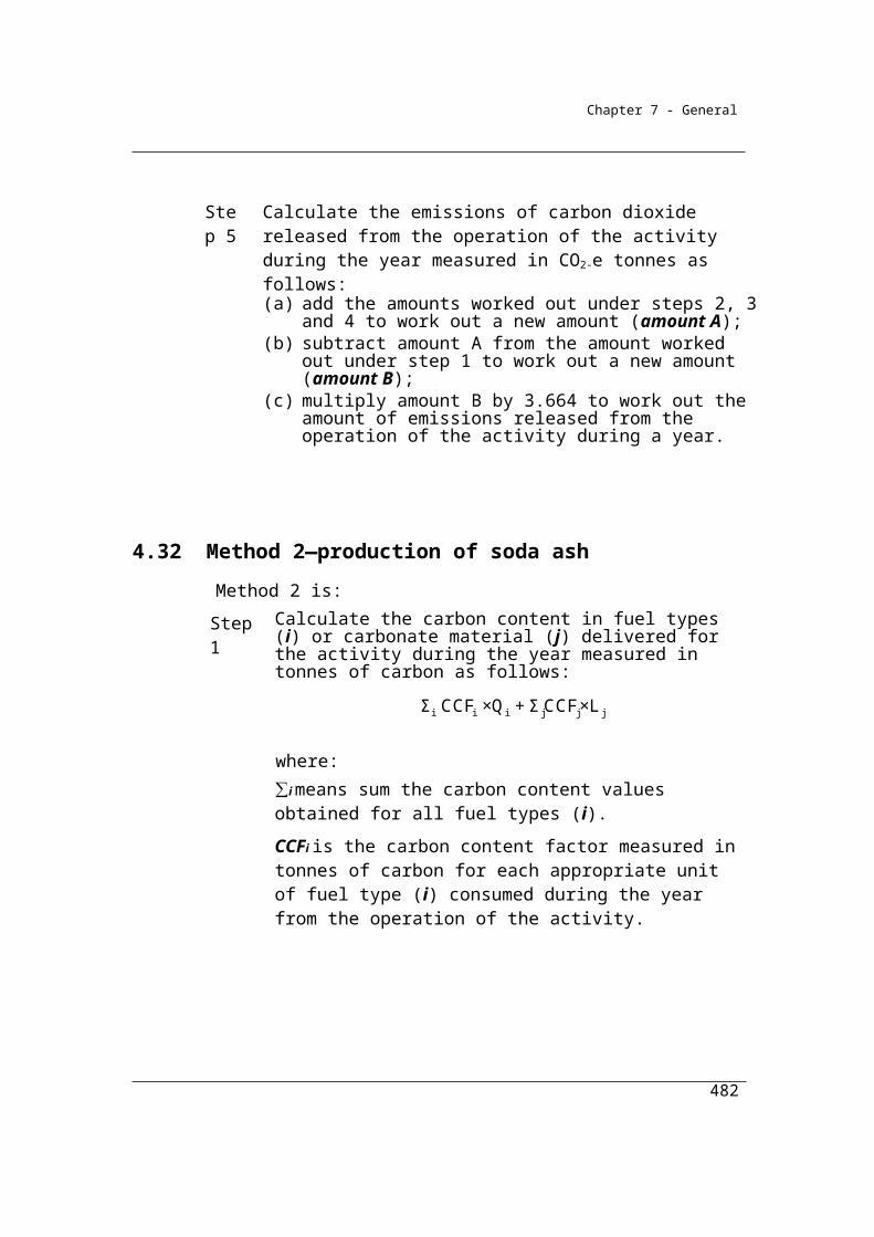
Chapter 7 - General
Division 5.3.2—Method 1—methane released from wastewater handling (domestic and commercial)
5.25 Method 1—methane released from wastewater handling (domestic and commercial)
Section 5.25 sets out Method 1 for wastewater handling – domestic and commercial.
Method 1 for wastewater handling is based on the National Greenhouse Accounts methods, except in certain circumstances, specified below.
Total greenhouse gas emissions from domestic and commercial wastewater are the sum of emissions from wastewater treatment and sludge treatment. The total quantity of wastewater treated depends on the size of the population that is generating wastewater.
Method 1 provides a method for estimating emissions in the absence of data on Chemical Oxygen Demand (COD) or Biochemical Oxygen Demand (BOD) estimates of on-site wastewater and sludge.
Section 5.25 sets out that under certain specific circumstances an alternative estimation approach should apply. These circumstances are for facilities that capture methane generated by the wastewater handling and where the estimates of the quantity of methane captured for combustion (either at the facility or elsewhere) or flaring exceed 75 per cent of the estimated emissions generated from the wastewater from the facility according to the application of the emissions generation model.
The method to be applied in these circumstances is as for the solid waste disposal method set out in section 5.4 with the exception of subsection (5) which provides a calculation specific to wastewater handling based on chemical oxygen demand (COD) in the wastewater and uses methane correction factors (MCFWW and MCFsl) for the wastewater and sludge. The methane correction factors are the fractions of COD anaerobically treated by the plant. Methane will only be generated through anaerobic treatment of the COD and emissions estimates must be corrected to eliminate any COD that is not anaerobically treated.
482

Chapter 7 - General
As for solid waste disposal, it is intended that Reporters will be able to use direct emissions monitoring systems to establish higher capture efficiencies and to establish emissions directly. This will require the development of direct monitoring methods. None have been specified in this Determination. Further development work and consultation is required to establish the appropriateness of various monitoring techniques before their inclusion.
The intent of the following equation is to reconcile the estimated theoretical amount of methane generated at the wastewater treatment plant (CH4*) with the actual amount of methane measured in the captured sludge biogas. The difference between the theoretical and measured amounts is assumed to be emitted to the atmosphere and forms the methane emissions estimate from wastewater handling for the facility.
(1) For subparagraph 5.24(1)(a)(i), method 1 is:
cap tr4j flaredE = CH (Q + Q + Q )
where:
Ej is the emissions of methane released by the plant during the year measured in CO2-e tonnes.
CH4* is the estimated quantity of methane in sludge biogas released by the plant during the year measured in CO2-e tonnes as determined under subsections (2) and (3).
γ is the factor 6.784 x 10-4 x 25 converting cubic metres of methane at standard conditions to CO2-e tonnes.
Qcap is the quantity of methane in sludge biogas captured for combustion for use by the plant during the year measured in cubic metres in accordance with Division 2.3.6.
Qflared is the quantity of methane in sludge biogas flared during the year by the plant measured in cubic metres in accordance with Division 2.3.6.
Qtr is the quantity of methane in sludge biogas transferred out of the plant during the year measured in cubic metres in accordance with Division 2.3.6.
(2) For subsection (1), if:
483
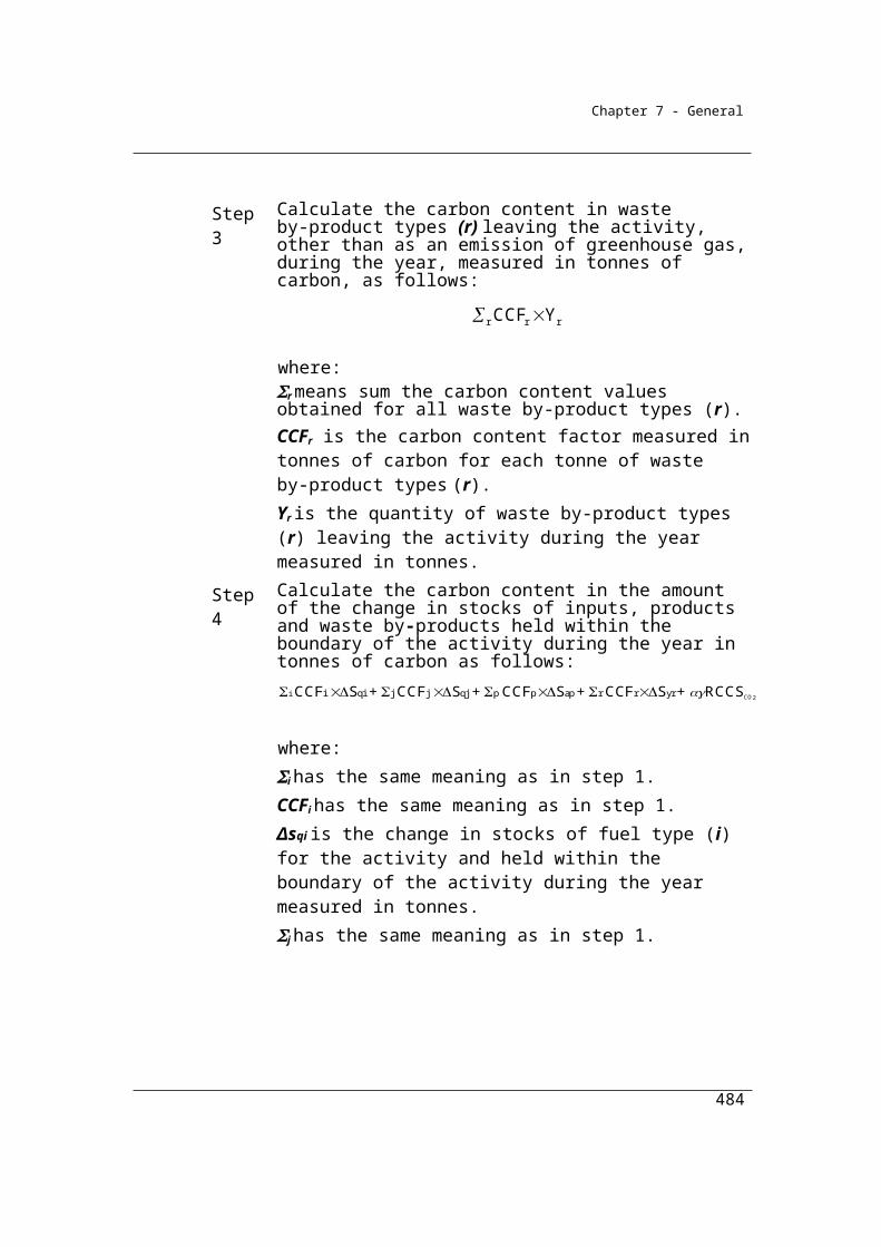
Chapter 7 - General
cap trflared
4gen
(Q + Q + Q )CH
is less than or equal to 0.75, then:*
4 4genCH = CH
where:
CH4gen is the quantity of methane in sludge biogas produced by the plant during the year, estimated in accordance with subsection (5) and measured in CO2-e tonnes.
(3) For subsection (1), if:
cap trflared
4gen
(Q + Q + Q )CH
is greater than 0.75, then:
*flared trcap4 + Q + Q 1CH = Q
0.75
where:
γ is the factor 6.784 x 10-4 x 25 converting cubic metres of methane at standard conditions to CO2-e tonnes.
Qcap is the quantity of methane in sludge biogas captured for combustion by the plant, measured in cubic metres in accordance with Division 2.3.6.
(4) For subsections (1) and (3), Qcap is to be calculated in accordance with Division 2.3.6.
(5) For subsection (2):
4gen w sl eff ww wij
sl trl tro sl slij
CH COD COD COD MCF EF
COD COD COD MCF EF
= ( )
+ ( )
where:
CODW is the factor worked out as follows:
w wCOD = P DC
where:
484

Chapter 7 - General
P is the population served by the operation of the plant during the year and measured in numbers of persons.
DCw is the quantity in tonnes of COD per capita of wastewater for a year using a default of 0.0585 tonnes per person.
CH4gen is the methane generated from commercial wastewater and sludge treatment by the plant during the year measured in CO2-e tonnes.
CODw is the chemical oxygen demand (COD) in wastewater entering the plant during the year measured in tonnes.
CODsl is the quantity of COD removed as sludge from wastewater and treated in the plant measured in tonnes of COD and worked out as follows:
psl waslslCOD COD COD=
where:
CODpsl is the quantity of COD removed as primary sludge from wastewater and treated in the plant measured in tonnes of COD and estimated under subsection (7).
CODwasl is the quantity of COD removed as waste activated sludge from wastewater and treated in the plant measured in tonnes of COD and estimated under subsection (8).
CODeff is the quantity of COD in effluent leaving the plant during the year measured in tonnes.
MCFww is the methane correction factor for wastewater treated at the plant during the year.Note: IPCC default methane correction factors for various types of treatment are:
managed aerobic treatment: 0 unmanaged aerobic treatment: 0.3 anaerobic digester/reactor: 0.8 shallow anaerobic lagoon (<2 metres): 0.2 deep anaerobic lagoon (>2 metres): 0.8.
EFwij is the default methane emission factor for wastewater with a value of 6.3 CO2-e tonnes per tonne COD.
CODtrl is the quantity of COD in sludge transferred out of the plant and removed to landfill measured in tonnes of COD.
CODtro is the quantity of COD in sludge transferred out of the plant and removed to a site other than landfill measured in tonnes of COD.
485

Chapter 7 - General
MCFsl is the methane correction factor for sludge treated at the plant during the year.Note: IPCC default methane correction factors for various types of treatment are:
managed aerobic treatment: 0 unmanaged aerobic treatment: 0.3 anaerobic digester/reactor: 0.8 shallow anaerobic lagoon (<2 metres): 0.2 deep anaerobic lagoon (>2 metres): 0.8.
EFslij is the default methane emission factor for sludge with a value of 6.3 CO2-e tonnes per tonne COD (sludge).
(6) For subsection (5), an operator of the plant must choose a treatment for MCFww and estimate the quantity of COD removed from the wastewater as sludge (CODsl).
(7) For subsection (5), CODpsl may be estimated using the following formula:
pslVS 1.99
where:
VSpsl is the estimated volatile solids in the primary sludge.
(8) For subsection (5), CODwasl may be estimated using the following formula:
waslVS 1.48
where:
VSwasl is the estimated volatile solids in the waste activated sludge.
(9) In this section:
methane correction factor is the fraction of COD anaerobically treated.
primary sludge means sludge from the first major treatment process in a wastewater treatment facility that is designed primarily to remove a substantial amount of suspended matter but little or no colloidal or dissolved matter.
waste activated sludge means sludge from a secondary treatment process in a wastewater treatment facility involving aeration and active biological material.
486
Chapter 7 - General
The intent of the equation in 5.25 (5) is to estimate the theoretical quantity of methane generated at the plant, based on a simple COD mass balance. The equation is divided into two parts.
The first part is a simple COD mass balance over the main wastewater treatment processes (i.e. “liquid train” primary and secondary treatment). The second part is a simple COD mass balance over the sludge treatment processes (e.g. anaerobic digesters, lagoons, dewatering, etc.).
Each COD mass balance determines how much COD is consumed in the treatment process by converting it to a gas. Multiplying by the maximum methane generation factor (EF) calculates how much CH4 would be generated if all the COD consumed is converted to CH4. Then, multiplying by the process-specific Methane Correction Factor (Fwan or Fslan) calculates the expected fraction of methane emissions for that particular type of process.
Fwan
PrimaryWastewater Treatment
Process
Secondary WastewaterTreatment
Process
Sludge Treatment
Process
CODw
CODpsl CODwasl
CODsl
CODwasl
CODtrl
CODtroFslan
Wastewater Treatment Plant
487
Chapter 7 - General
Division 5.3.3—Method 2—methane released from wastewater handling (domestic and commercial)
Division 5.3.3 sets out Method 2 for the estimation of methane emissions from wastewater handling, which requires estimates of Chemical Oxygen Demand concentrations in wastewater estimated using general sampling provisions for the Guidelines and analysis conducted in accordance with listed Australian or international standards or an equivalent standard. It is likely that many facilities collect this data routinely for existing regulatory reasons.
5.26 Method 2—methane released from wastewater handling (domestic and commercial)
(1) Method 2 is:
Step 1. Calculate the amount of emissions of methane released for each sub-facility of a plant during the reporting year, measured in CO2-e tonnes, using the equation:
where:
γ is the factor 6.784 x 10-4 x 25 for converting cubic metres of methane at standard conditions to CO2-e tonnes.
CH4genz is the estimated quantity of methane in sludge biogas generated by the sub-facility during the reporting year, worked out in accordance with subsection (2), measured in CO2-e tonnes.
Qcapz is the quantity of methane in sludge biogas that is captured for combustion by the sub-facility during the reporting year, measured in cubic metres in accordance with Division 2.3.6.
Qflaredz is the quantity of methane in sludge biogas flared by the sub-facility during the reporting year, measured in cubic metres in accordance with Division 2.3.6.
488

Chapter 7 - General
Qtrz is the quantity of methane in sludge biogas transferred out of the plant during the reporting year by the sub-facility, measured in cubic metres in accordance with Division 2.3.6.Note: For the number of sub-facilities a plant operator may select and
requirements in relation to each sub-facility, see section 5.26A.
Step 2. To calculate the amount of methane emissions released by the plant during the reporting year, measured in CO2-e tonnes, add together the amount worked out for each sub-facility under step 1.
(2) Subject to subsection (8), the factor CH4genz in subsection (1) is worked out for a sub-facility as follows:
Step 1. Calculate the following for the sub-facility:
where:
γ has the same meaning as in step 1 in subsection (1).
CODeffz is the quantity of COD in effluent leaving the sub-facility during the reporting year, measured in tonnes of COD and calculated by using:
(a) facility operating data that measures the volumetric effluent rate and the effluent rate of COD concentration; or
(b) if data is available on the biochemical oxygen demand (BOD) in the effluent—that data converted to COD in accordance with the following formula:
CODslz is the quantity of COD removed as sludge from wastewater and treated in the sub-facility, measured in tonnes of
489
Chapter 7 - General
COD and worked out using the formula mentioned in subsection (4).
CODtrlz is the quantity of COD in sludge transferred out of the sub-facility and removed to landfill, measured in tonnes of COD.
CODtroz is the quantity of COD in sludge transferred out of the sub-facility and removed to a site other than landfill, measured in tonnes of COD.
CODwz is the quantity of COD in wastewater entering the sub-facility during the year, measured in tonnes of COD and calculated by using:
(a) facility operating data that measures the volumetric influent rate and the influent rate of COD concentration; or
(b) if data is available on the biochemical oxygen demand (BOD) in the wastewater—that data converted to COD in accordance with the following formula:
EFslijz is the default methane emission factor for sludge with a value of 6.3 CO2-e tonnes per tonne of COD (sludge).
EFwijz is the default methane emission factor for wastewater with a value of 6.3 CO2-e tonnes per tonne of COD.
MCFslz is the methane correction factor for sludge treated at the sub-facility during the reporting year.
MCFwwz is the methane correction factor for wastewater treated at the sub-facility during the reporting year.
Qcapz has the same meaning as in step 1 in subsection (1).
Qflaredz has the same meaning as in step 1 in subsection (1).
Qtrz has the same meaning as in step 1 in subsection (1).
Step 2. If the quantity worked out under step 1 is less than or equal to 1.00, work out CH4genz using the following formula:
490

Chapter 7 - General
where:
CODeffz has the same meaning as in step 1.
CODslz has the same meaning as in step 1.
CODtrlz has the same meaning as in step 1.
CODtroz has the same meaning as in step 1.
CODwz has the same meaning as in step 1.
EFslijz has the same meaning as in step 1.
EFwijz has the same meaning as in step 1.
MCFwwz has the same meaning as in step 1.
MCFslz has the same meaning as in step 1.
Step 3. If the quantity worked out under step 1 is greater than 1.00, work out CH4genz using the formula:
where:
γ has the same meaning as in step 1 in subsection (1).
Qcapz has the same meaning as in step 1 in subsection (1).
Qflaredz has the same meaning as in step 1 in subsection (1).
Qtrz has the same meaning as in step 1 in subsection (1).
(3) For steps 1 and 2 in subsection (2), an operator of the plant must choose a treatment for MCFwwz and estimate the quantity of COD removed from the wastewater as sludge (CODslz).
491
Chapter 7 - General
(4) For steps 1 and 2 in subsection (2), CODslz is worked out using the formula:
where:
CODpslz is the quantity of COD removed as primary sludge from wastewater and treated in the sub-facility measured in tonnes of COD and may be estimated using the formula in subsection (5).
CODwaslz is the quantity of COD removed as waste activated sludge from wastewater and treated in the sub-facility measured in tonnes of COD and may be estimated using the formula in subsection (6).
(5) For subsection (4), CODpslz may be estimated in accordance with the following formula:
where:
VSpslz is the estimated volatile solids in the primary sludge.
(6) For subsection (4), CODwaslz may be estimated in accordance with the following formula:
where:
VSwaslz is the estimated volatile solids in the waste activated sludge.
(7) Wastewater used for the purposes of subsection (2) must be sampled and analysed for COD in accordance with the requirements in sections 5.27, 5.28 and 5.29.
(8) If the sub-facility is an anaerobic sludge lagoon, the method set out in the document entitled “Fugitive Emissions from Sludge Lagoons Technical Paper”, published by the Water Services Association of Australia in April 2014, may be used to estimate CH4genz for the sub-facility.Note: The Fugitive Emissions from Sludge Lagoons Technical Paper could in 2014
be viewed on the Water Services Association of Australia’s website (http://www.wsaa.asn.au).
(9) In this section:
methane correction factor is the fraction of COD anaerobically treated.
492
Chapter 7 - General
Note: IPCC default methane correction factors for various types of treatment are as follows:(a) managed aerobic treatment: 0;(b) unmanaged aerobic treatment: 0.3;(c) anaerobic digester/reactor: 0.8;(d) shallow anaerobic lagoon (<2 metres): 0.2;(e) deep anaerobic lagoon (>2 metres): 0.8.
primary sludge means sludge from the first major treatment process in a wastewater treatment facility that is designed primarily to remove a substantial amount of suspended matter but little or no colloidal or dissolved matter.
waste activated sludge means sludge from a secondary treatment process in a wastewater treatment facility involving aeration and active biological material.
5.26A Requirements relating to sub-facilities
(1) A plant operator may select one or more sub-facilities for the plant to estimate emissions released by the plant.
(2) A sub-facility selected:(a) must be an area within a plant covering a discrete treatment stage;
and(b) must have a uniform treatment of COD so that the estimates of the
methane generated by the sub-facility are consistent with the principles mentioned in section 1.13; and
(c) must not be subject to:(i) sludge biogas inflow from another sub-facility; or
(ii) sludge biogas outflow to another sub-facility.
5.27 General requirements for sampling under method 2
(1) A sample must be representative of the wastewater and the COD concentrations at the plant.
(2) The samples must be collected on enough occasions to produce a representative sample.
(3) The samples must also be free of bias so that any estimates are neither over nor under estimates of the true value.
(4) Bias may be tested in accordance with an appropriate standard (if any).
493

Chapter 7 - General
(5) The value obtained from the sample must only be used for the plant for which it was intended to be representative.
5.28 Standards for analysis
(1) Samples of wastewater must be analysed for COD in accordance with:(a) ISO 6060:1989; or(b) sections 5220B, 5220C or 5220D of APHA (1995); or(c) an equivalent Australian or international standard.
(2) Samples of wastewater must be analysed for BOD in accordance with:(a) AS 4351.5—1996; or(b) section 5210B of APHA (1995); or(c) an equivalent Australian or international standard.
5.29 Frequency of sampling and analysis
Wastewater must be sampled and analysed on at least a monthly basis.
494

Chapter 7 - General
Division 5.3.4—Method 3—methane released from wastewater handling (domestic and commercial)
Division 5.3.4 sets out Method 3 for the estimation of methane emissions from wastewater handling, which requires estimates of Chemical Oxygen Demand concentrations in wastewater estimated using sampling and analysis conducted in accordance with listed Australian or international standards or an equivalent standard.
5.30 Method 3—methane released from wastewater handling (domestic and commercial)
(1) For subparagraph 5.24(a)(iii) and subject to subsection (2), method 3 is the same as method 2 under section 5.26.
(2) In applying method 2 under section 5.26, the wastewater must be sampled in accordance with AS/NZS 5667.10:1998 or an equivalent Australian or international standard.
495
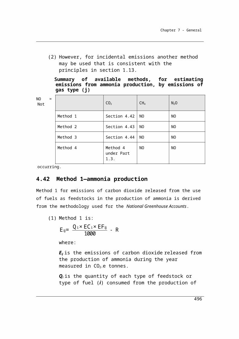
Chapter 7 - General
Division 5.3.5—Method 1—emissions of nitrous oxide released from wastewater handling (domestic and commercial)
5.31 Method 1—nitrous oxide released from wastewater handling (domestic and commercial)
Section 5.31 sets out Method 1 for the estimation of nitrous oxide emissions.
(1) For paragraph 5.24(1)(b), method 1 is:
troj in trl outdisij secij outdisij disijE = (N N N N ) EF + N EF
where:
Ej is the emissions of nitrous oxide released from human sewage treated by the plant during the year, measured in tonnes of nitrous oxide and expressed in CO2-e tonnes.
Nin is the quantity of nitrogen entering the plant during the year, measured in tonnes of nitrogen and worked out:
(a) for primary wastewater treatment plants, using the following formula:
Nin = Ntrl + Ntro + Noutdisij
where:
Ntrl is the quantity of nitrogen in sludge transferred out of the plant and removed to landfill during the year, measured in tonnes of nitrogen and worked out using the following formula:
trl Ntrl trlN F M
Ntro is the quantity of nitrogen in sludge transferred out of the plant and removed to a site other than landfill during the year, measured in tonnes of nitrogen and worked out as follows:
tro Ntro troN F M
Noutdisij is the quantity of nitrogen leaving the plant, differentiated by discharge environment; or(b) for any other kind of wastewater treatment plant, using the following
formula:
496
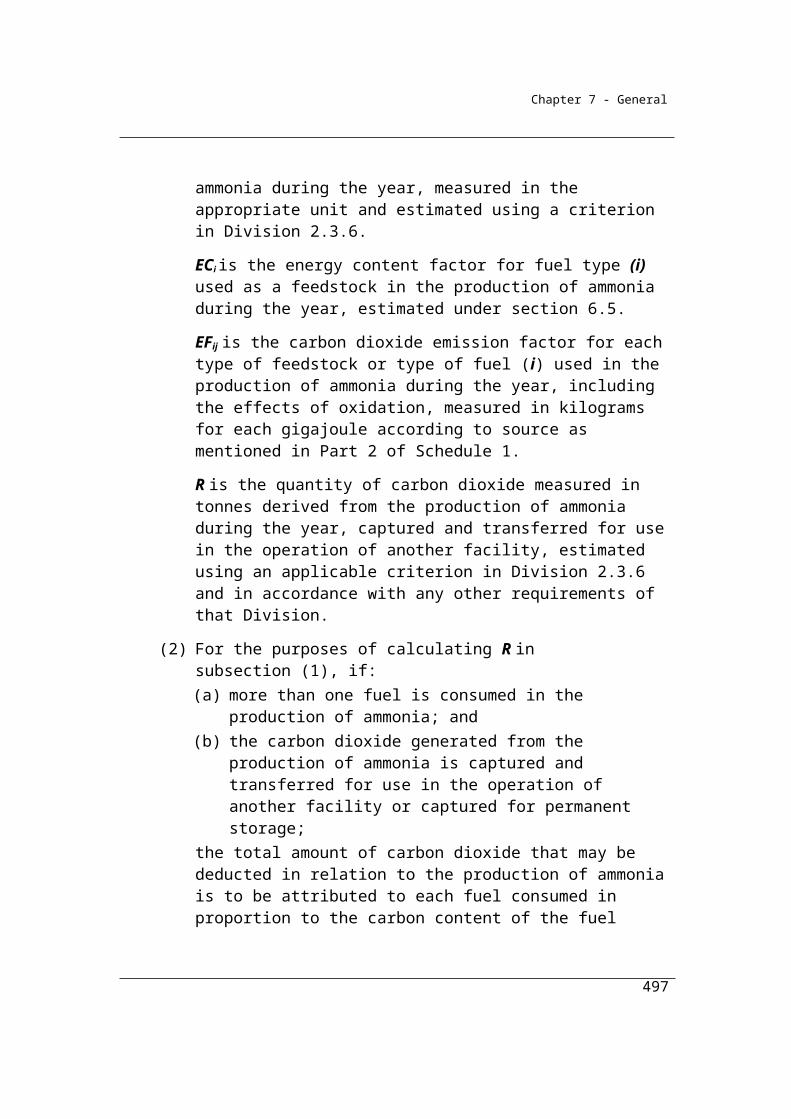
Chapter 7 - General
PrinN = Protein Frac P
where:
Protein is the annual per capita protein intake of the population being served by the plant, measured in tonnes per person.
FracPr is the fraction of nitrogen in protein.
P is the population serviced by the plant during the year.
Ntrl is the quantity of nitrogen in sludge transferred out of the plant and removed to landfill during the year, measured in tonnes of nitrogen and worked out as follows:
trl Ntrl trlN F M
where:
FNtrl is the fraction of nitrogen in the sludge transferred out of the plant.
Mtrl is the dry mass of sludge transferred out of the plant to landfill during the year, measured in tonnes.
Ntro is the quantity of nitrogen in sludge transferred out of the plant and removed to a site other than landfill during the year, measured in tonnes of nitrogen and worked out as follows:
tro Ntro troN F M
where:
FNtro is the fraction of nitrogen in the sludge transferred out of the plant to a site other than landfill.
Mtro is the dry mass of sludge transferred out of the plant to a site other than landfill during the year, measured in tonnes.
Noutdisij is the quantity of nitrogen leaving the plant, differentiated by discharge environment.
EFsecij is the emission factor for wastewater treatment.
EFdisij is the emission factor for nitrogen discharge, differentiated by the discharge environment.
(2) For Protein in subsection (1), the annual per capita protein intake is 0.036 tonnes per year.
497

Chapter 7 - General
(3) For FracPr in subsection (1), the factor is 0.16 tonnes of nitrogen per tonne of protein.
(4) For FNtrl and FNtro in subsection (1), the factor is 0.05.
(5) For Noutdisij in subsection (1), discharge environments mentioned in column 2 of an item of the following table are defined in column 3 for the item.
Item Discharge environment
Definition
1 Enclosed waters All waters other than open coastal waters or estuarine waters2 Estuarine waters All waters (other than open coastal waters) that are:
(a) ordinarily subject to tidal influence; and(b) enclosed by a straight line drawn between the low water
marks of consecutive headlands3 Open coastal waters
(ocean and deep ocean)
(a) for New South Wales—has the meaning given by the definition of open coastal waters in Schedule 3 to the Protection of the Environment Operations (General) Regulation 2009 (NSW), as in force on 8 June 2012; and
(b) otherwise—means all waters of the Pacific Ocean, Southern Ocean and Indian Ocean, except those waters enclosed by a straight line drawn between the low water marks of consecutive headlands
Note: Historical versions of the Protection of the Environment Operations (General) Regulation 2009 (NSW) are available at www.legislation.nsw.gov.au.
(6) For EFsecij in subsection (1), the emission factor is 4.9 tonnes of nitrous oxide, measured in CO2-e per tonne of nitrogen produced.
(7) For EFdisij in subsection (1), the emission factor mentioned in column 3 of an item of the following table must be used for the discharge environment mentioned in column 2 for the item.
Item Discharge environment EFdisij
1 Enclosed waters 4.72 Estuarine waters 1.23 Open coastal waters (ocean and deep ocean) 0.0
498
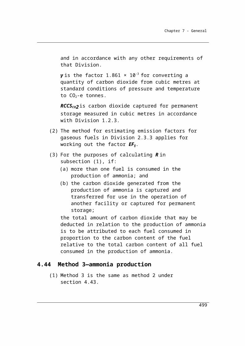
Chapter 7 - General
Division 5.3.6—Method 2—emissions of nitrous oxide released from wastewater handling (domestic and commercial)
Section 5.32 to 5.35 sets out Method 2 for the estimation of nitrous oxide emissions from wastewater handling. Method 2 requires the sampling and analysis of nitrogen quantities in the wastewater and sludge in accordance with listed Australian or international standards or an equivalent standard. It is likely that many facilities collect this data routinely for regulatory reasons.
5.32 Method 2—nitrous oxide released from wastewater handling (domestic and commercial)
(1) For subparagraph 5.24(1)(b)(ii) and subject to this section, method 2 is the same as method 1 under section 5.31.
(2) In applying method 1 under section 5.31, nitrogen must be calculated:(a) by using facility operating data that measures the volumetric influent
and effluent rates and the influent and effluent rates of nitrogen concentrations; or
(b) for primary wastewater treatment plants, using the following formula:
Nin = Ntrl + Ntro + Noutdisij
where:
Nin is the quantity of nitrogen entering the plant during the year, measured in tonnes of nitrogen.
Ntrl is the quantity of nitrogen in sludge transferred out of the plant and removed to landfill during the year, measured in tonnes of nitrogen and worked out using the following formula:
trl Ntrl trlN F M
Ntro is the quantity of nitrogen in sludge transferred out of the plant and removed to a site other than landfill during the year, measured in tonnes of nitrogen and worked out as follows:
tro Ntro troN F M
499

Chapter 7 - General
Noutdisij is the quantity of nitrogen leaving the plant, differentiated by discharge environment.
(3) Wastewater used for the purposes of subsection (2), must be sampled and analysed for nitrogen in accordance with the requirements in sections 5.33, 5.34 and 5.35.
5.33 General requirements for sampling under method 2
(1) A sample must be representative of the wastewater and the nitrogen concentrations at the plant.
(2) The samples must be collected on enough occasions to produce a representative sample.
(3) The samples must also be free of bias so that any estimates are neither over nor under estimates of the true value.
(4) Bias must be tested in accordance with an appropriate standard (if any).
(5) The value obtained from the sample must only be used for the plant for which it was intended to be representative.
5.34 Standards for analysis
(1) Samples of wastewater must be analysed for nitrogen in accordance with:(a) ISO 11905-1:1997; or(b) sections 4500-Norg B, 4500-Norg C or 4500-Norg D of APHA (1995);
or(c) an equivalent Australian or international standard.
(2) Samples of sludge must be analysed for nitrogen in accordance with:(a) EN 13342:2000; or(b) section 4500-Norg B of APHA (1995); or(c) an equivalent Australian or international standard.
5.35 Frequency of sampling and analysis
Wastewater must be sampled and analysed on at least a monthly basis.
500
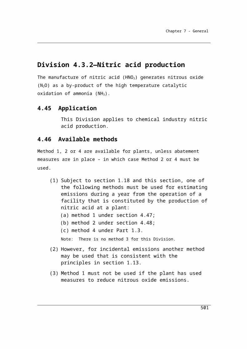
Chapter 7 - General
Division 5.3.7—Method 3—emissions of nitrous oxide released from wastewater handling (domestic and commercial)
5.36 Method 3—nitrous oxide released from wastewater handling (domestic and commercial)
Section 5.36 sets out Method 3 for the estimation of nitrous oxide emissions from wastewater handling. Method 3 is very similar to Method 2, except that sampling of the water and sludge must be undertaken in accordance with listed Australian or international standards or an equivalent standard.
(1) For subparagraph 5.24(1)(b)(iii) and subject to subsection (2), method 3 is the same as method 2 under section 5.32.
(2) In applying method 2 under section 5.32, the wastewater must be sampled in accordance with AS/NZS 5667.10:1998 or an equivalent Australian or international standard.
(3) In applying method 2 under section 5.32, the sludge must be sampled in accordance with ISO 5667-13:1997 or an equivalent Australian or international standard.
501
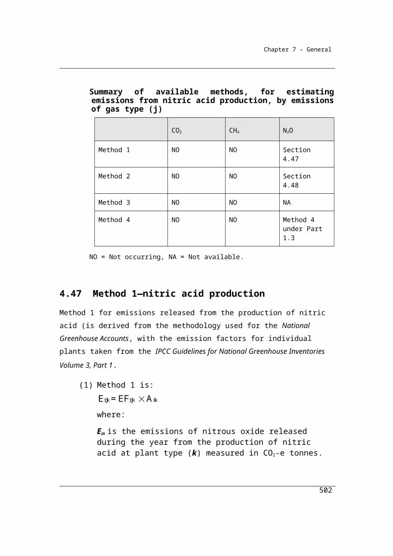
Chapter 7 - General
Division 5.3.8—Wastewater handling (domestic and commercial)—Flaring
Sections 5.37-5.39 set out Methods 1, 2 and 3 for the flaring of gas. Method 1 is derived from the methods used for the National Greenhouse Accounts. Methods 2 and 3 rely on the sampling and analysis of the fuel to estimate the gas composition of the fuel in order to estimate the quantity of methane flared more accurately.
5.37 Method 1—Flaring of methane in sludge biogas from wastewater handling (domestic and commercial)
(1) For subparagraph 5.24(1)(c)(i), method 1 is:
ijj flared flared i
EFE = Q EC
where
Ej flared is the emissions of gas type (j) released from the plant from flaring of the methane in sludge biogas from the plant during the year measured in CO2-e tonnes.
Qflared is the quantity of methane in sludge biogas flared from the plant during the year measured in cubic metres in accordance with Division 2.3.6.
ECi is the energy content factor of methane in sludge biogas in gigajoules per cubic metre (see Schedule 1).
EFij is the relevant emission factor for gas type (j) for methane in sludge biogas measured in CO2-e per gigajoule (see Schedule 1).
(2) For Qflared in subsection (1), the methane in sludge biogas is taken to constitute 70% of the sludge biogas.
5.38 Method 2—flaring of methane in sludge biogas
(1) For subparagraph 5.24(1)(c)(ii) and subject to this section, method 2 is the same as method 1 under section 5.37.
(2) In applying method 1 under section 5.37, Qflared must be determined in accordance with the sampling and analysis requirements in Subdivision 2.3.3.2 and the measuring requirements in Division 2.3.6.
502
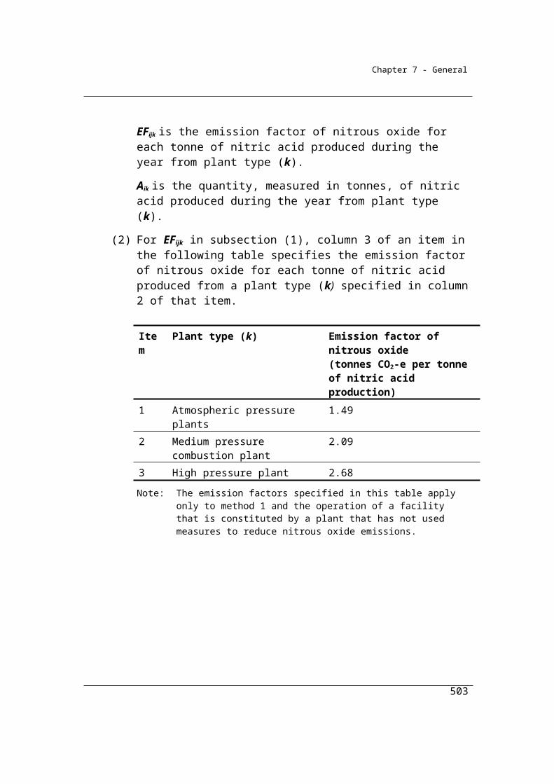
Chapter 7 - General
5.39 Method 3—flaring of methane in sludge biogas
(1) For subparagraph 5.24(1)(c)(iii) and subject to this section, method 3 is the same as method 1 under section 5.37.
(2) In applying method 1 under section 5.37, Qflared must be determined in accordance with the sampling and analysis requirements in Division 2.3.4 and the measuring requirements in Division 2.3.6.
503
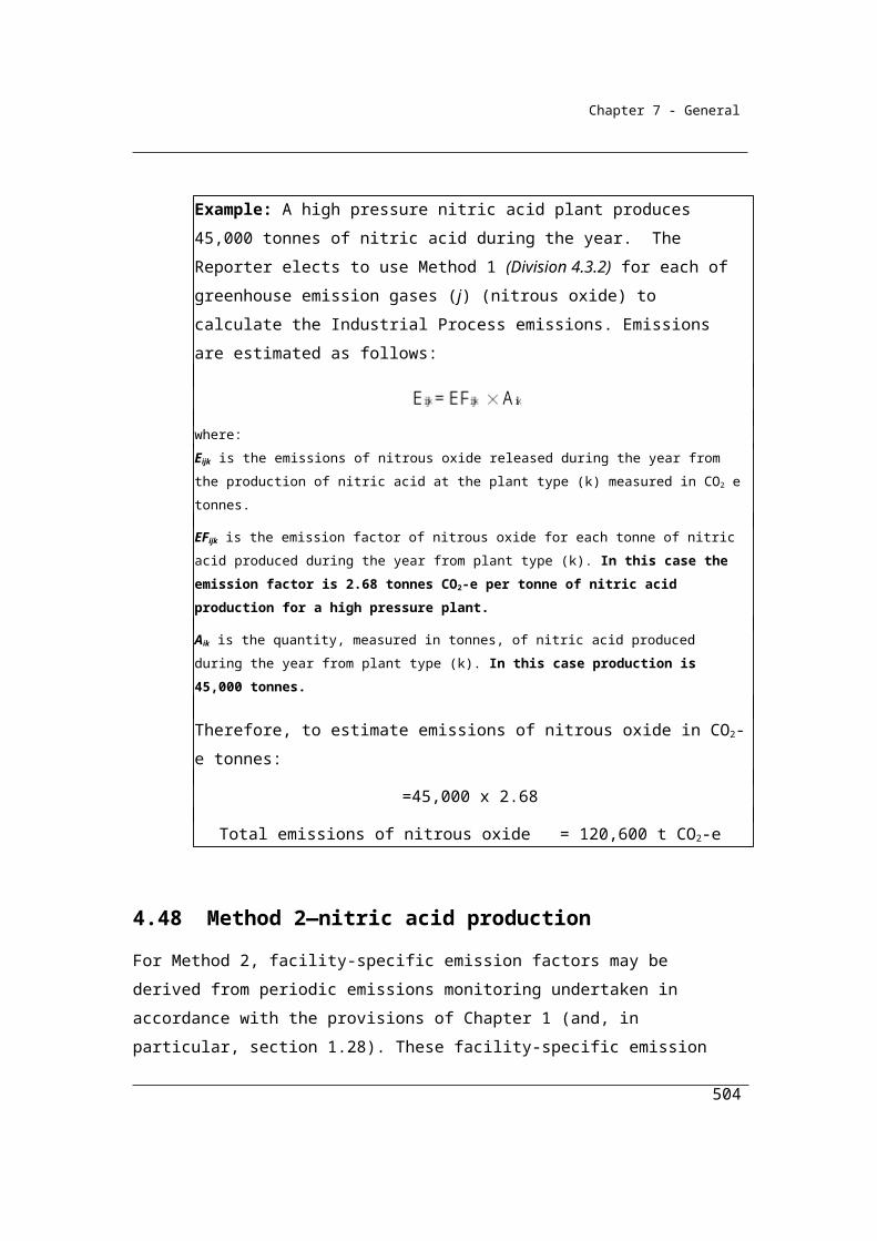
Chapter 7 - General
Part 5.4—Wastewater handling (industrial)
Division 5.4.1—Preliminary
5.40 Application
(1) This Part applies to emissions released from the decomposition of organic material and the flaring of sludge biogas, resulting from the handling of industrial wastewater through treatment in wastewater collection and treatment systems.
(2) In this section, industrial wastewater means liquid wastes and sludge resulting from the production of a commodity, by an industry, mentioned in column 1 of an item of the table in subsection 5.42(8).
5.41 Available methods
(1) Subject to section 1.18 one of the following methods must be used for estimating emissions of methane released from the operation of a facility (other than by flaring of landfill gas containing methane) that is constituted by wastewater handling generated by the relevant industries (the plant) during a year:
(a) method 1 under section 5.42;(b) method 2 under section 5.43;(c) method 3 under section 5.47.
(2) Subject to section 1.18, one of the following methods must also be used for estimating emissions of each gas type released as a result of methane in sludge biogas flared from the operation of the plant during a year:
(a) method 1 under section 5.48;(b) method 2 under section 5.49;(c) method 3 under section 5.50.
(3) Under subsection (2), the same method must be used for estimating emissions of each gas type.
(4) For incidental emissions another method may be used that is consistent with the principles in section 1.13.Note: There is no method 4 for subsection (1) or (2).
504

Chapter 7 - General
Summary of available methods, by emissions of gas type (j)
CO2 CH4 N2O
Domestic and Commercial waste water management
Method 1 NA Section 5.42 NO
Method 2 NA Section 5.43 NO
Method 3 NA Section 5.47 NO
Method 4 NA NA NO
Methane flared from the operation of the facility
Method 1 NA Section 5.48 Section 5.48
Method 2 NA Section 5.49 Section 5.49
Method 3 NA Section 5.50 Section 5.50
Method 4 NA NA NA
NA = Not available. NO = Not occurring.
505

Chapter 7 - General
Division 5.4.2—Method 1—methane released from wastewater handling (industrial)
5.42 Method 1—methane released from wastewater handling (industrial)
Section 5.42 sets out Method 1 for methane emissions from wastewater handling – industrial. It is intended that this method applies to industries producing the following commodities under the applicable ANZSIC codes:
Dairy products (ANZSIC code 113)
Pulp, paper and paperboard (ANZSIC code 1510)
Meat and poultry (ANZSIC codes 1111 and 1112)
Organic chemicals (ANZSIC codes 18 and 19)
Raw sugar (ANZSIC code 1181)
Beer (ANZSIC code 1212)
Wine and Other Alcoholic Beverages (ANZSIC code 1214)
Fruit and vegetables (ANZSIC code 1140)
ANZSIC codes and descriptions of the activities included under each code can be found on the Australian Bureau of Statistics website at http://www.abs.gov.au.
Note the definition of raw sugar is as follows:
raw sugar has the meaning given by Chapter 17, Section IV, Schedule 3 of the Customs Tariff Act 1995
The following is an excerpt from Chapter 17, Section IV, Schedule 3 of the Customs Tariff Act 1995
“ “raw sugar” means sugar whose content of sucrose by weight, in the dry state,
corresponds to a polarimeter reading of less than 99.55.”
506
Chapter 7 - General
As for domestic and commercial wastewater handling facilities, Method 1 for industrial wastewater handling is based on the National Greenhouse Accounts methods, except in certain circumstances.
It is intended in time that Reporters will be able to use direct emissions monitoring systems to establish higher capture efficiencies and to establish emissions directly. This will require the development of direct monitoring methods. None have been specified in these Guidelines. Further development work and consultation is required to establish the appropriateness of various monitoring techniques before their inclusion.
(1) For paragraph 5.41(1)(a), method 1 is:
cap tr4j flaredE = CH (Q + Q + Q )
where:
Ej is the emissions of methane released from the plant during the year measured in CO2-e tonnes.
CH4* is the estimated quantity of methane in sludge biogas generated by
the plant during the year measured in CO2-e tonnes as determined under subsections (2) and (3).
γ is the factor 6.784 × 10⁻⁴.× 25 converting cubic metres of methane at standard conditions to CO2-e tonnes.
Qcap is the quantity of methane in sludge biogas captured for combustion for the plant during the year measured in cubic metres in accordance with Division 2.3.6.
Qflared is the quantity of methane in sludge biogas flared by the plant during the year measured in cubic metres in accordance with Division 2.3.6.
Qtr is the quantity of methane in sludge biogas transferred out of the plant during the year measured in cubic metres in accordance with Division 2.3.6.
(2) For subsection (1), if:
cap trflared
4gen
(Q + Q + Q )CH
is less than or equal to 0.75, then:
507
Chapter 7 - General
*4 4genCH = CH
where:
CH4gen is the quantity of methane in sludge biogas produced by the plant during the year, estimated in accordance with subsection (5) and measured in CO2-e tonnes.
(3) For subsection (1), if:
cap trflared
4gen
(Q + Q + Q )CH
is greater than 0.75, then:
*flared trcap4
1+ Q + Q0.75
CH = Q
where:
γ is the factor 6.784 x 10-4 x 25 converting cubic metres of methane at standard conditions to CO2-e tonnes.
Qcap is the quantity of methane in sludge biogas captured for combustion for the operation of the plant measured in cubic metres.
(4) For subsections (1) and (3), Qcap is to be calculated in accordance with Division 2.3.6.
(5) For subsection (2) the factor CH4gen is estimated as follows:
where:
Σw,i is the total CODw,i of wastewater entering the plant.
CODw,i is the COD in wastewater entering the plant related to the production by the plant of any commodity mentioned in column 1 of the table in subsection (8) during the year measured in tonnes of COD, worked out as follows:
con,iw,i i gen,i
CODCOD = Prod W
1 000
where:
508
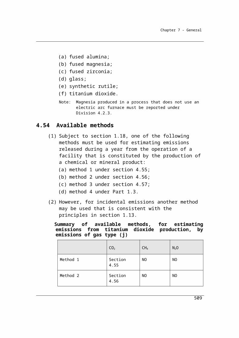
Chapter 7 - General
Prodi has the meaning given by the table in subsection 5.42(9).
Wgen,i is the wastewater generation rate from the production of any commodity mentioned in column 1 of the table in subsection (8) produced during the year and measured in cubic metres or kilolitres per tonne of commodity.
CODcon,i is the COD concentration in kilograms of COD per cubic metre of wastewater entering the plant during the year from the production of any commodity mentioned in column 1 of the table in subsection (8).
CODsl is the quantity of COD removed as sludge from wastewater during the year measured in tonnes of COD, worked out as follows:
sl w,i slCOD = COD F
where:
CODw,i is the COD in wastewater entering the plant used in the production of any commodity mentioned in column 1 of the table in subsection (8) during the year measured in tonnes of COD.
Fsl is the fraction of COD removed from wastewater as sludge by the plant during the year.
CODeff is the quantity of COD effluent leaving the plant during the year, measured in tonnes.
MCFww is the methane correction factor for wastewater treated at the plant during the year.Note: IPCC default methane correction factors for various types of treatment are:
managed aerobic treatment: 0 unmanaged aerobic treatment: 0.3 anaerobic digester/reactor: 0.8 shallow anaerobic lagoon (<2 metres): 0.2 deep anaerobic lagoon (>2 metres): 0.8.
EFwij is the methane emission factor for industrial wastewater.
CODtrl is the quantity of COD in sludge transferred out of the plant and removed to landfill during the year measured in tonnes of COD.
CODtro is the quantity of COD in sludge transferred out of the plant and removed to a site other than landfill during the year measured in tonnes of COD.
509
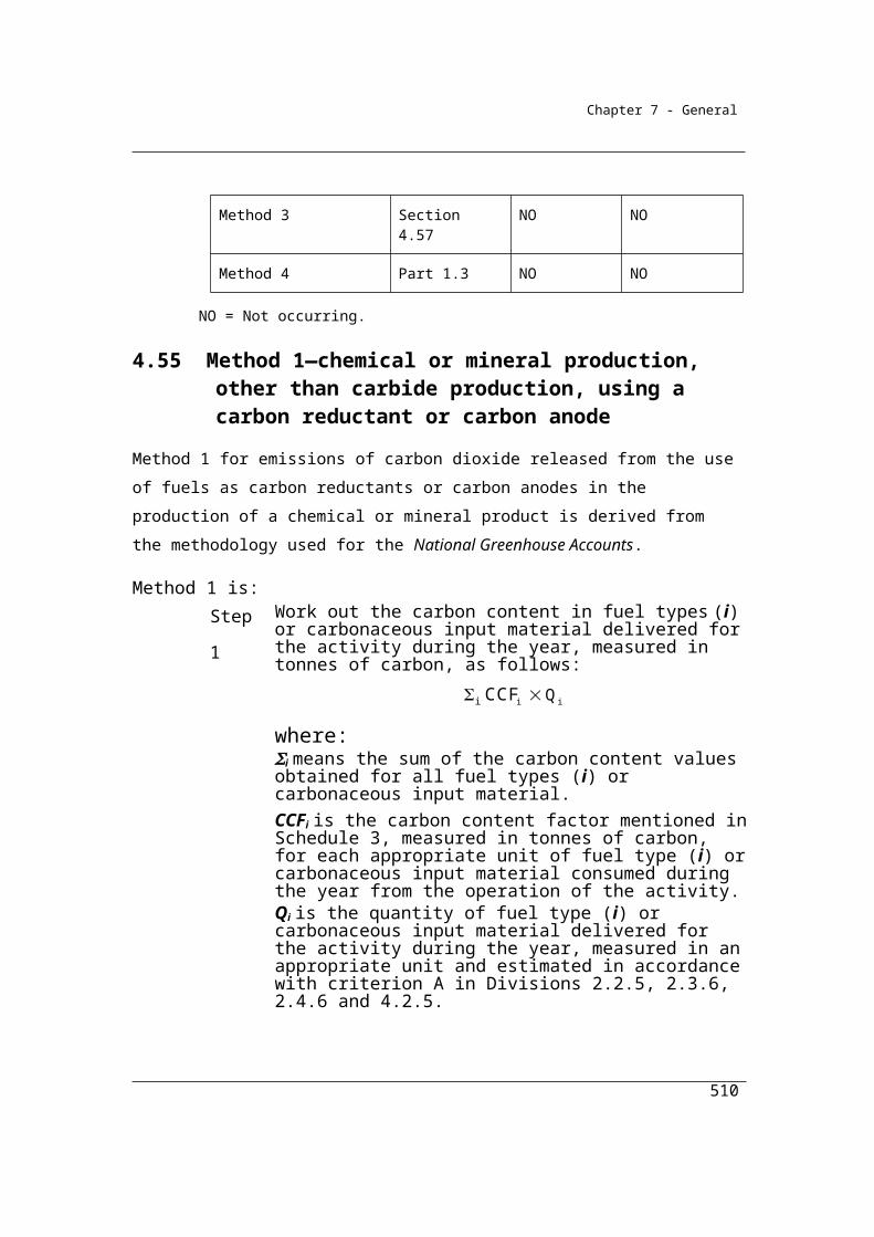
Chapter 7 - General
MCFsl is the methane correction factor for sludge treated at the plant during the year.
While default MCF values are provided under method 1, it is also possible to self select an appropriate MCF value based on the type of wastewater treatment system employed in the industrial plant. The following table is provided to assist in the MCF selection process.
Note: IPCC default methane correction factors for various types of treatment are: managed aerobic treatment: 0 unmanaged aerobic treatment: 0.3 anaerobic digester/reactor: 0.8 shallow anaerobic lagoon (<2 metres): 0.2 deep anaerobic lagoon (>2 metres): 0.8.
EFslij is the methane emission factor for the treatment of sludge by the plant.
(6) For EFwij in subsection (5), an emission factor of 6.3 CO2-e tonnes per tonne of COD may be used.
(7) For EFslij in subsection (5), a methane emission factor of 6.3 CO2-e tonnes per tonne of COD may be used.
(8) For subsection (5), COD must be estimated for a commodity set out in column 1 of an item in the following table that is produced by the industry referred to by the ANZSIC code set out in column 1 for that item:
(a) by using the default values for Wgen,i and CODcon,i set out in columns 2 and 3 for that item; or
(b) in accordance with industry practice relevant to the measurement of the quantity of wastewater.
Estimate of COD for a commodity and industryItem Column 1 Column 2 Column 3
Commodity and industry Wgen,i
default valueCODcon,i
default value1 Dairy product (ANZSIC code 113) 5.7 0.92 Pulp, paper and paperboard (ANZSIC
code 1510)26.7 0.4
3 Meat and poultry (ANZSIC codes 1111 and 1112)
13.7 6.1
4 Organic chemicals (ANZSIC codes 18 and 19)
67.0 3.0
510
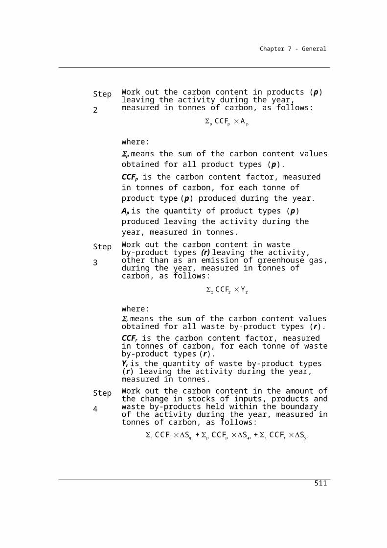
Chapter 7 - General
Estimate of COD for a commodity and industryItem Column 1 Column 2 Column 3
Commodity and industry Wgen,i
default valueCODcon,i
default value5 Raw sugar (ANZSIC code 1181) 0.4 3.86 Beer (ANZSIC code 1212) 5.3 6.07 Wine and other alcoholic beverage
(ANZSIC code 1214)23.0 1.5
8 Fruit and vegetable (ANZSIC code 1140)
20.0 0.2
(9) For subsection (5), Prodi is the amount of any commodity set out in column 2 of an item in the following table, produced by the industry set out in column 2 for that item, and measured in accordance with the corresponding units of measurement set out in column 3 for that item.
Item Commodity and industry Units of measurement1 Dairy product (ANZSIC code 113) tonne of product2 Pulp, paper and paperboard (ANZSIC code 1510) tonne of product3 Meat and poultry (ANZSIC codes 1111 and 1112) tonne of product4 Organic chemicals (ANZSIC codes 18 and 19) tonne of product5 Raw sugar (ANZSIC code 1181) tonne of product6 Beer (ANZSIC code 1212) tonne of product 7 Wine and other alcoholic beverage (ANZSIC code
1214)tonne of product
8 Fruit and vegetable (ANZSIC code 1140) tonne of product
(10) In this section:
methane correction factor is the fraction of COD anaerobically treated.
511

Chapter 7 - General
Division 5.4.3—Method 2—methane released from wastewater handling (industrial)
5.43 Method 2—methane released from wastewater handling (industrial)
Sections 5.43-5.46 set out Method 2 for wastewater handling. Method 2 requires estimates of Chemical Oxygen Demand concentrations in wastewater estimated using general sampling provisions for these Guidelines and analysis conducted in accordance with listed Australian or international standards or an equivalent standard.
(1) For paragraph 5.41(1)(b) and subject to this section, method 2 for wastewater handling (industrial) is the same as method 1 under section 5.42.
(2) In applying method 1 under section 5.42, each mention of CODw,i in subsection 5.42(5) must be estimated from wastewater entering the plant and must be calculated by using:
(a) facility operating data that measures the volumetric influent rate and the influent rate of COD concentrations; or
(b) if data is available on the biochemical oxygen demand (BOD) in the wastewater—that data converted to COD in accordance with the following formula:
5COD = 2.6 BOD
(2A) In applying method 1 under section 5.42, the reference to 0.75 in subsections 5.42(2) and (3) is to read as a reference to 1.00.
(3) Wastewater used for the purposes of subsection (2), must be sampled and analysed for COD in accordance with the requirements in sections 5.44, 5.45 and 5.46.
5.44 General requirements for sampling under method 2
(1) A sample must be representative of the wastewater and the COD concentrations at the plant.
(2) The samples must be collected on enough occasions to produce a representative sample.
512

Chapter 7 - General
(3) The samples must also be free of bias so that any estimates are neither over nor under estimates of the true value.
(4) Bias must be tested in accordance with an appropriate standard (if any).
(5) The value obtained from the sample must only be used for the plant for which it was intended to be representative.
5.45 Standards for analysis
(1) Samples of wastewater must be analysed for COD in accordance with:(a) ISO 6060:1989; or(b) sections 5220B, 5220C or 5220D of APHA (1995); or(c) an equivalent Australian or international standard.
(2) Samples of wastewater must be analysed for BOD in accordance with:(a) AS 4351.5—1996; or(b) section 5210B of APHA (1995); or(c) an equivalent Australian or international standard.
5.46 Frequency of sampling and analysis
Wastewater must be sampled and analysed on at least a monthly basis.
513
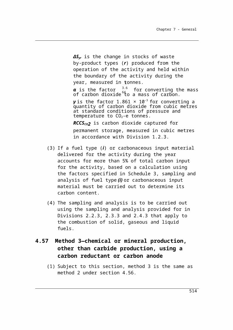
Chapter 7 - General
Division 5.4.4—Method 3—methane released from wastewater handling (industrial)
5.47 Method 3—methane released from wastewater handling (industrial)
Section 5.47 sets out Method 3 for wastewater handling. The Method requires estimates of Chemical Oxygen Demand concentrations in wastewater estimated using sampling and analysis conducted in accordance with listed Australian or international standards or an equivalent standard.
(1) For paragraph 5.41(1)(c) and subject to subsection (2), method 3 is the same as method 2 under section 5.43.
(2) In applying method 2 under section 5.43, the wastewater must be sampled in accordance with AS/NZS 5667.10:1998 or an equivalent Australian or international standard.
514
Chapter 7 - General
Division 5.4.5—Wastewater handling (industrial)—Flaring of methane in sludge biogas
Sections 5.48-5.50 set out Methods 1, 2 and 3 for the flaring of methane in sludge biogas. Method 1 is derived from the methods used for the National Greenhouse Accounts. Methods 2 and 3 rely on the sampling and analysis of the fuel to estimate the gas composition of the fuel in order to estimate the quantity of methane flared more accurately.
5.48 Method 1—flaring of methane in sludge biogas
(1) For paragraph 5.41(2)(a), method 1 is:
ijj flared flared i
EFE = Q EC
1 000
where:
Ej flared is the emissions of gas type (j) released from flaring of the methane in sludge biogas by the plant during the year measured in CO2-e tonnes.
Qflared is the quantity of methane in sludge biogas flared by the plant during the year measured in cubic metres in accordance with Division 2.3.6.
ECi is the energy content factor of methane in sludge biogas measured in gigajoules per cubic metre (see Schedule 1).
EFij is the relevant emission factor for gas type (j) for methane in sludge biogas in CO2-e tonnes per gigajoule (see Schedule 1).
(2) For Qflared in subsection (1), the methane in sludge biogas is taken to constitute 70% of the sludge biogas.
5.49 Method 2—flaring of methane in sludge biogas
(1) For paragraph 5.41(2)(b) and subject to this section, method 2 is the same as method 1 under section 5.48.
(2) In applying method 1 under section 5.48, Qflared must be determined in accordance with the sampling and analysis requirements in Subdivision 2.3.3.2 and the measuring requirements in Division 2.3.6.
515
Chapter 7 - General
5.50 Method 3—flaring of methane in sludge biogas
(1) For paragraph 5.41(2)(c) and subject to this section, method 3 is the same as method 1 under section 5.48.
(2) In applying method 1 under section 5.48, Qflared must be determined in accordance with the sampling and analysis requirements in Division 2.3.4 and the measuring requirements in Division 2.3.6.
516

Chapter 7 - General
Part 5.5—Waste incineration
5.51 Application
This Part applies to emissions released from waste incineration, other than incineration for energy production.
5.52 Available methods—emissions of carbon dioxide from waste incineration
(1) Subject to section 1.18, one of the following methods must be used for estimating emissions of carbon dioxide released from the operation of a facility that is constituted by waste incineration (the plant):
(a) method 1 under section 5.53;(b) method 4 under Part 1.3.
Note: There is no method 2 or 3 for this section.
(2) For incidental emissions, another method may be used that is consistent with the principles in section 1.13.
5.53 Method 1—emissions of carbon dioxide released from waste incineration
(1) Method 1 is:
i i i i iE = Q CC FCC OF 3.664
where:
Ei is the emissions of carbon dioxide released from the incineration of waste type (i) by the plant during the year measured in CO2-e tonnes.
Qi is the quantity of waste type (i) incinerated by the plant during the year measured in tonnes of wet weight value in accordance with:
(a) Division 2.2.5 for solid fuels; and(b) Division 2.3.6 for gaseous fuels; and (c) Division 2.4.6 for liquid fuels.
CCi is the carbon content of waste type (i).
FCCi is the proportion of carbon in waste type (i) that is of fossil origin.
517
Chapter 7 - General
OFi is the oxidation factor for waste type (i).
(2) If waste materials other than clinical wastes have been incinerated by the plant, appropriate values for the carbon content of the waste material incinerated must be derived from Schedule 3.
(3) For CCi in subsection (1), the IPCC default of 0.60 for clinical waste must be used.
(4) For FCCi in subsection (1), the IPCC default of 0.40 for clinical waste must be used.
(5) For OFi in subsection (1), the IPCC default of 1.00 for clinical waste must be used.
518

Chapter 7 - General
Chapter 6—Energy
Part 6.1—Production
6.1 Purpose
The purpose of this Part is to provide for the estimation of the energy content of energy produced from the operation of a facility during a year.Note 1: Energy produced from the operation of a facility is dealt with in
regulation 2.25 of the Regulations.
Note 2: Energy includes the fuels and energy commodities listed in Schedule 1 to the Regulations. See the definition of energy in section 7 of the Act and in regulation 2.03 of the Regulations.
6.2 Quantity of energy produced
(1) The quantity of an energy produced from the operation of the facility during the year must be estimated:
(a) if the energy is a solid or gaseous fuel—in accordance with industry practice; or
(b) if the energy is a liquid fuel—by either of the following:(i) using bulk filling meters corrected to 15° celsius;
(ii) by the physical measurement of the fuel corrected to its notional volumetric equivalent at a temperature of 15° Celsius; or
(c) if the energy is electricity produced for use during the operation of the facility—as the difference between:(i) the amount of electricity produced by the electricity generating
unit for the facility as measured at the unit’s terminals; and(ii) the sum of the amounts of electricity supplied to an electricity
transmission or distribution network measured at the connection point for the network in accordance with either of the measurement requirements specified in subsection (3) and the amount of electricity supplied for use outside the operation of the facility that is not supplied to the network; or
(d) if the energy is electricity produced for use outside the operation of the facility other than for supply to an electricity transmission network or distribution network—as the amount of electricity supplied for use outside the operation of the facility that is not supplied to an electricity transmission or distribution network; or
519
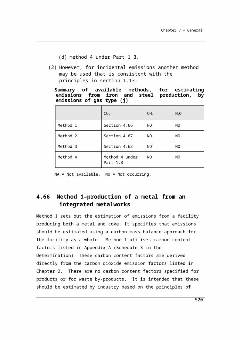
Chapter 7 - General
(e) if the energy is electricity supplied to an electricity transmission or distribution network—as the amount of electricity for use outside the operation of the facility for supply to the network measured at the connection point for the network in accordance with either of the measurement requirements specified in subsection (3).
Note: Energy includes the fuels and energy commodities listed in Schedule 1 to the Regulations. See the definition of energy in section 7 of the Act and regulation 2.03 of the Regulations.
(1A) For incidental energy production, another method may be used that is consistent with the principles in section 1.13.
(2) For subsection (1), if the fuel is coal, its quantity must be estimated in the form of saleable coal on a washed basis.
(3) For paragraphs (1)(c) and (e), the measurement requirements are as follows:
(a) Chapter 7 of the National Electricity Rules made under the National Electricity Law set out in the National Electricity (South Australia) Act 1996;
(b) metering requirements applicable to the region in which the facility is located.
An example of metering requirements applicable to a region is the Wholesale Electricity Market Amending Rules in Western Australia’s South West Interconnected System.
The requirements above are generally sourced from definitions contained in the National Electricity Rules and measurement requirements from the Generator Efficiency Standards program.
The metering requirements specified in 6.2 (3) apply to the measurement of electricity supplied to an electricity transmission and distribution network measured at the connection point to the network.
Metering requirements are not specified for the amount of electricity produced by the electricity generation unit measured at the unit’s terminals or the amount supplied for use outside the facility which is not supplied to the network. Measurement of these quantities of electricity should make use of existing data and be consistent with the general principles set out in 1.13.
520

Chapter 7 - General
6.3 Energy content of fuel produced
(1) The energy content of a kind of energy (fuel) produced from the operation of the facility during the year is to be worked out as follows:
i i iZ = Q C
where:
Zi is the energy content of fuel type (i) produced during the year and measured in gigajoules.
Qi is the quantity of fuel type (i) produced during the year.
ECi is the energy content factor of fuel type (i), measured as energy content according to the fuel type measured in gigajoules:
(a) as mentioned in Schedule 1; or(b) in accordance with Divisions 2.2.3 and 2.2.4 (solid fuels),
Divisions 2.3.3 and 2.3.4 (gaseous fuels) or Divisions 2.4.3 and 2.4.4 (liquid fuels); or
(c) for electricity measured in kilowatt hours, ECi is equal to 0.0036; or(d) for fuels measured in gigajoules, ECi is equal to 1.
Note: Energy includes the fuels and energy commodities listed in Schedule 1 to the Regulations. See the definition of energy in section 7 of the Act and regulation 2.03 of the Regulations.
(2) The amount of electricity produced from the operation of the facility during the year must be evidenced by invoices, contractual arrangements or industry metering records.
Estimates of energy produced do not enter emission calculations and will be used for statistical purposes. Further development of these specifications may be necessary, however, depending on the development of policy in relation to emissions trading and, in particular, the use of the concept of upstream liability.
521

Chapter 7 - General
Part 6.2—Consumption
6.4 Purpose
The purpose of this Part is to provide for the estimation of the energy content of energy consumed from the operation of a facility during a year.Note 1: Energy includes the fuels and energy commodities listed in Schedule 1 to the
Regulations. See the definition of energy in section 7 of the Act and regulations 2.03 of the Regulations.
Note 2: Energy consumed from the operation of a facility is dealt with in regulation 2.23 of the Regulations.
Note 3: Energy consumed is subject to the thresholds mentioned in sections 2.2, 2.18 and 2.39 of this Determination.
Calculating the energy content of fuels and energy commodities consumed is an intermediate step in the estimation of emissions from fuel combustion using methods 1, 2 or 3 in Chapter 2. Consequently this data will serve the dual purpose of providing an estimation of energy consumed and a step in the estimation of emissions.
6.5 Energy content of energy consumed
(1) The energy content of a kind of energy (fuel) consumed from the operation of the facility during the year is to be worked out as follows:
i i iZ = Q C
where:
Zi is the energy content of fuel type (i) consumed during the year and measured in gigajoules.
Qi is the quantity of fuel type (i) consumed during the year estimated in accordance with:
(a) Parts 2.2 (solid fuels), 2.3 (gaseous fuels) and 2.4 (liquid fuels); or(b) subsection (2) for electricity.
ECi, is the energy content factor of fuel type (i) and is:(a) for solid fuels, measured in gigajoules per tonne:
(i) as mentioned in Part 1 or Part 7 of Schedule 1; or
522
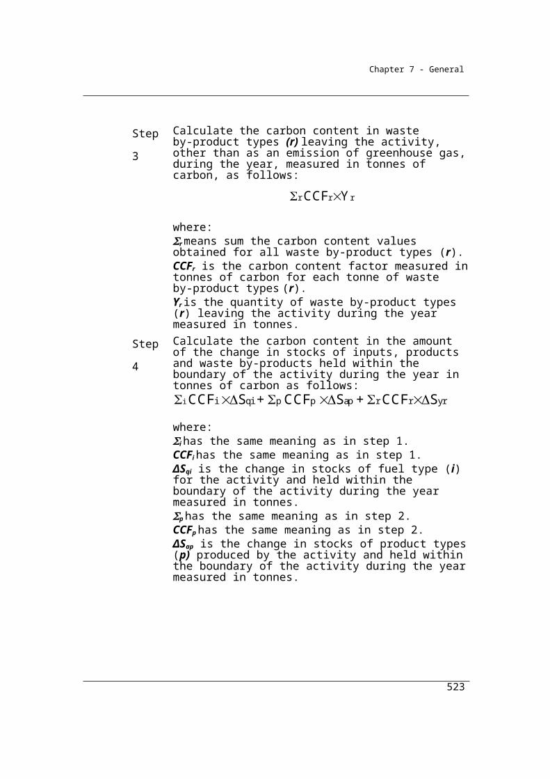
Chapter 7 - General
(ii) estimated by analysis of the fuel in accordance with the standard indicated for that energy content factor in Schedule 2 or an equivalent standard; or
(b) for gaseous fuels, measured in gigajoules per cubic metre: (i) as mentioned in Part 2 or Part 7 of Schedule 1; or
(ii) estimated by analysis under Subdivision 2.3.3.2; or(c) for gaseous fuels measured in gigajoules—equal to 1; or (d) for liquid fuels, measured in gigajoules per kilolitre:
(i) as mentioned in Part 3 or Part 7 of Schedule 1 for stationary energy purposes; or
(ii) as mentioned in Division 4.1 or Part 7 of Schedule 1 for transport energy purposes; or
(iii) estimated by analysis under Subdivision 2.4.3.2; or(e) for electricity measured in kilowatt hours—equal to 0.0036.
Note: Energy includes the fuels and energy commodities listed in Schedule 1 to the Regulations. See the definition of energy in section 7 of the Act and regulation 2.03 of the Regulations.
(1A) Despite subsection (1), if:(a) the kind of energy is one of the following:
(i) solar energy for electricity generation;(ii) wind energy for electricity generation;
(iii) water energy for electricity generation;(iv) geothermal energy for electricity generation; and
(b) the energy is consumed from the operation of the facility during the year; and
(c) from that consumption of energy, electricity is produced from the operation of the facility during the year;
then the energy content of the consumed energy is taken to be equal to the energy content of the electricity produced as estimated under Part 6.1.
(2) The amount of electricity consumed from the operation of the facility during the year must be:
(a) evidenced by invoices, contractual arrangements or industry metering records; or
(b) estimated in accordance with industry practice, if the evidence under paragraph (a) is unavailable.
(3) If, in relation to a year:(a) a method used by a person requires the ECi factor to be estimated
under this section in relation to a particular fuel type (i); and
523
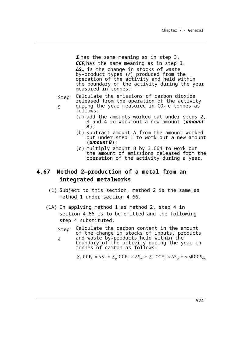
Chapter 7 - General
(b) a way of estimating is chosen for the fuel type as required by this section; and
(c) other methods used by the person for the same fuel type also require the ECi factor to be estimated under this section;
then the chosen way of estimating, and the amount estimated, must also be applied in using the other methods for the fuel type in relation to that year.
524
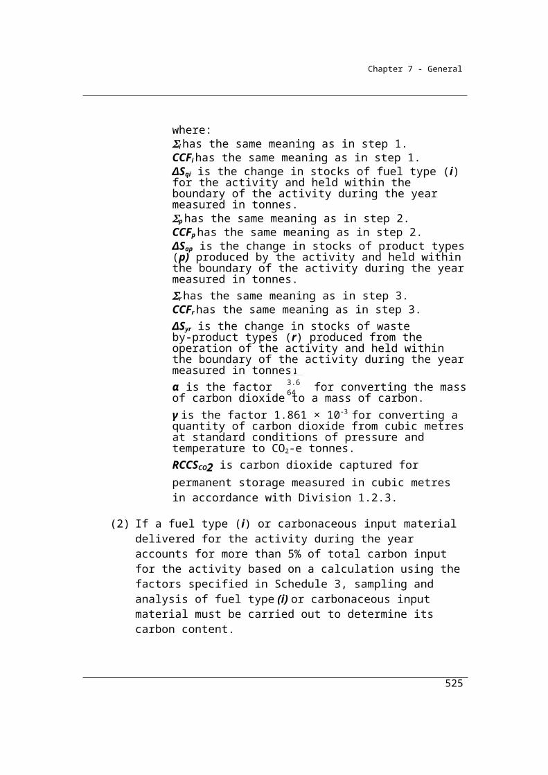
Chapter 7 - General
Chapter 7—Scope 2 emissions
7.1 Application
Chapters 1-5 relate to the estimation of scope 1 emissions.
This chapter concerns scope 2 emissions which result from activities that generate electricity, heating, cooling or steam that is consumed by a facility but that do not form part of the facility. This Chapter applies if the amount of purchased electricity consumed from the operation of a facility during a year that result in scope 2 emissions is more than 20 000 kilowatt hours.
Measuring and reporting energy consumption and scope 2 emissions from purchased electricity are optional if the amount purchased that results in scope 2 emissions is less than 20,000 kilowatt hours at a facility. Companies may continue to report these emissions if it is more efficient to do so.
This chapter specifies a method of determining scope 2 emissions from the consumption of purchased electricity that has been used by the Greenhouse Challenge Plus for over a decade. The method is applicable for electricity consumed by transmission and distribution companies, consistent with The Greenhouse Gas Protocol: A Corporate Accounting and Reporting Standard of the World Resources Institute/World Business Council for Sustainable Development (the GHG Protocol). The method accommodates electricity measured either in kilowatt hours or gigajoules.
Scope 2 emissions factors are be updated each year.
Scope 2 emissions also arise from electricity acquired from off-grid sources that do not form part of the facility. These Scope 2 emissions may be estimated using section 7.3 below. Emission factors can be provided by the supplier of the electricity, or if unavailable, the emission factor for NT may be used. NT electricity generation primarily represents a mix of natural gas and diesel generation which is a reasonable match for the fuel mix used in the generation of off-grid electricity generation.
(1) This Chapter specifies a method of determining scope 2 emissions from the consumption of purchased electricity.
525
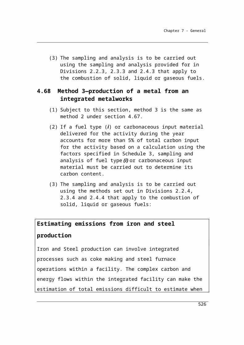
Chapter 7 - General
(2) This Chapter applies if the amount of purchased electricity consumed from the operation of a facility during a year that results in scope 2 emissions is more than 20 000 kilowatt hours.
(3) The facilities to which this Chapter applies include a facility the operation of which is constituted by an electricity transmission network or distribution network that consumes electricity through electricity losses.Note: Scope 2 emissions result from activities that generate electricity, heating,
cooling or steam that is consumed by a facility but that do not form part of the facility (see regulation 2.24 of the Regulations).
7.2 Method 1—purchase of electricity from main electricity grid in a State or Territory
(1) The following method must be used for estimating scope 2 emissions released from electricity purchased from the main electricity grid in a State or Territory and consumed from the operation of a facility during a year:
EFY = Q 1 000
where:
Y is the scope 2 emissions measured in CO2-e tonnes.
Q, subject to subsection (2), is the quantity of electricity purchased from the electricity grid during the year and consumed from the operation of the facility measured in kilowatt hours.
EF is the scope 2 emission factor, in kilograms of CO2-e emissions per kilowatt hour, for the State or Territory in which the consumption occurs as mentioned in Part 6 of Schedule 1.Note: There is no other method for this section.
(2) For a facility the operation of which is constituted by an electricity transmission network or distribution network, Q is the quantity of electricity losses for that transmission network or distribution network during the year.
(3) For Q, if the electricity purchased (or lost) is measured in gigajoules, the quantity of kilowatt hours must be calculated by dividing the amount of gigajoules by 0.0036.
(4) The main electricity grid, for a State or Territory, means:(a) for Western Australia—the Southwest Interconnected System; and
526
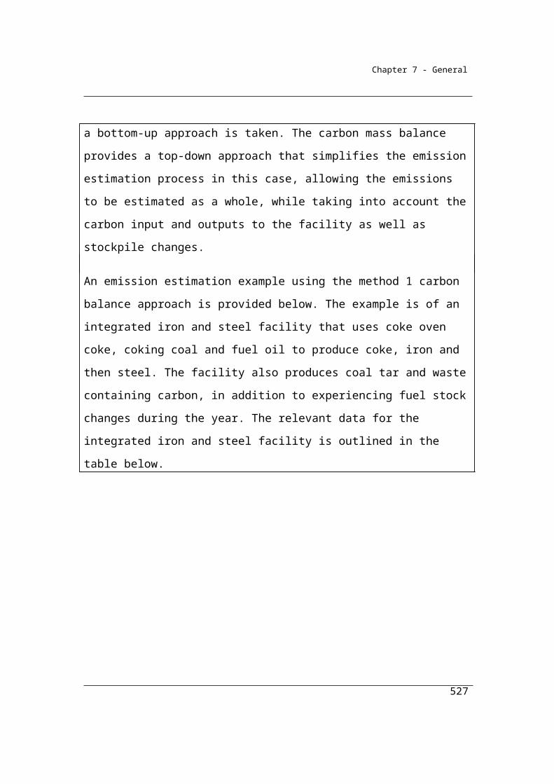
Chapter 7 - General
(b) for each other State or Territory—the electricity grid that provides electricity to the largest percentage of the State’s or Territory’s population.
7.3 Method 1—purchase of electricity from other sources
(1) The following formula must be used for estimating scope 2 emissions released from electricity:
(a) purchased from a grid other than the main electricity grid in a State or Territory; and
(b) consumed from the operation of a facility during a year:
EFY = Q 1 000
where:
Y is the scope 2 emissions measured in CO2-e tonnes during the year.
Q, subject to subsection (2), is the quantity of electricity purchased during the year and consumed from the operation of the facility, measured in kilowatt hours.
EF is the scope 2 emission factor, in kilograms of CO2-e emissions per kilowatt hour, either:
(a) provided by the supplier of the electricity; or (b) if that factor is not available, the emission factor for the Northern
Territory as mentioned in Part 6 of Schedule 1.Note: There is no other method for this section.
(2) For a facility the operation of which is constituted by an electricity transmission network or distribution network, Q is the quantity of electricity losses for that transmission network or distribution network during the year.
(3) For Q, if the electricity purchased (or lost) is measured in gigajoules, the quantity of kilowatt hours must be calculated by dividing the amount of gigajoules by 0.0036.
527

Chapter 7 - General
Table 7.2 Indirect (scope 2) emission factors from consumption of purchased electricity from a grid
Item State, Territory or grid description Emission factor
kg CO2-e/kWh
77 New South Wales and Australian Capital Territory 0.8478 Victoria 1.0979 Queensland 0.7880 South Australia 0.5381 South West Interconnected System in Western Australia 0.7282 Tasmania 0.1283 Northern Territory 0.67
528
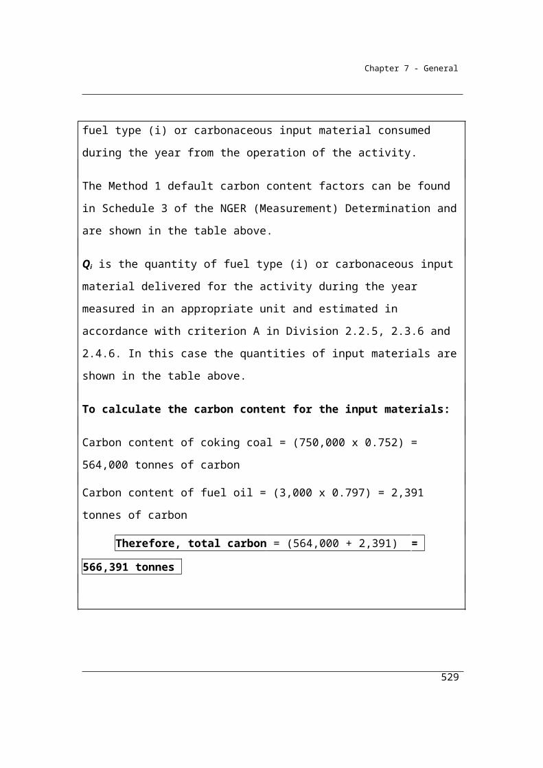
Chapter 7 - General
Other Scope 2 Emissions
Scope 2 emissions also arise from heating, cooling, or steam acquired from outside the facility.
These Scope 2 emissions may be estimated in consultation with the vendor of the heating, cooling or steam to ensure consistency and completeness with the vendor’s estimates of scope 1 emissions for those energy commodities.
Example A
A company has operations in NSW and Queensland. A component of the company’s energy use is electricity purchased from the grid. During the year the NSW operations consumed 11,300,000 kWh of electricity, while the Queensland operations consumed 14,600,000 kWh. Emissions are estimated as follows:
Y = Q x EF/1000
where:
Y is the scope 2 emissions.
Q is the quantity of electricity purchased from the electricity grid measured in kilowatt hours. In this case, 11,300,000 kWh from NSW and 14,600,000 kWh from QLD.
EF is the scope 2 emission factor, in either kilograms of CO2 e emissions per kilowatt hour for the State or Territory in which the consumption occurs as specified in Part 6 of Schedule 1 (of the Determination). In this case it is 0.87 kg CO2-e/kWh for NSW and 0.82 CO2-e/kWh for QLD.
Therefore, to calculate Scope 2 emissions:
For NSW operations
=(11,300,000 x 0.84)/1000
= 9,492 t Scope 2 CO2-e
For QLD operations
=(14,600,000 x 0.79)/1000
529
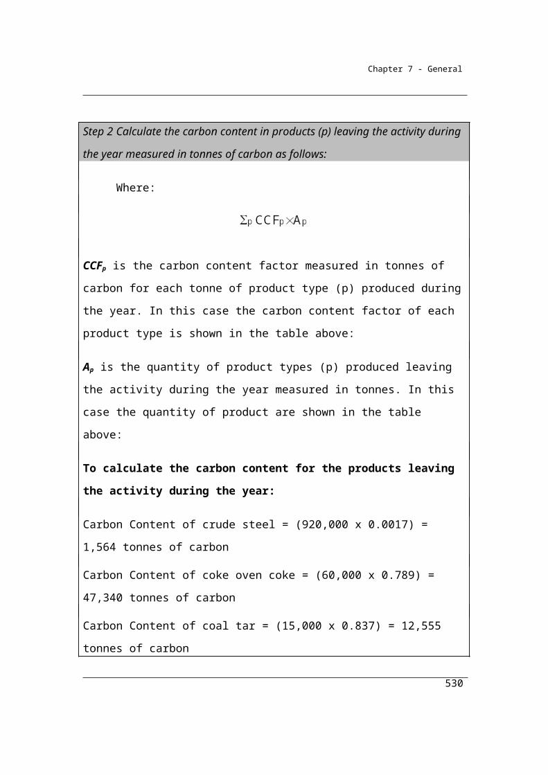
Chapter 7 - General
= 11,534 t Scope 2 CO2-e
Example B
A company uses steam from another facility to provide heat and returns condensate back to the other facility. During the year the company consumed 5,700 gigajoules of energy from the steam. Emissions are estimated as follows:
Y = Q x EF/1000
where:
Y is the scope 2 emissions.
Q is the quantity of steam purchased from the other facility. In this case the quantity of steam purchased is 5,700 GJ.
EF is the scope 2 emission factor for the steam, in this case measured in kg CO2-e/GJ. The vendor has provided a scope 2 emission factor for the steam of 400 kg CO2-e/GJ.
Therefore, to calculate Scope 2 emissions:
Scope 2 emissions
= (5,700 x 400) / 1000
= 2280 t Scope 2 CO2-e
The scope 2 emission factors are state-based emission factors from on-grid electricity generation calculated systematically from the physical characteristics of the electricity grid. The state-based emission factor calculates an average emission factor for all electricity consumed from the grid in a given state, territory or electricity grid. All emissions attributable to a state territory or grid’s electricity consumption are allocated amongst individual consumers in proportion to their relative level of consumption. In effect, the likelihood of a particular generator supplying a particular consumer is assumed to reflect each generator’s relative level of supply to the grid. The reason for this approach is that within an electricity grid it is impossible to physically trace or control the actual physical source of electricity received by each customer.
530
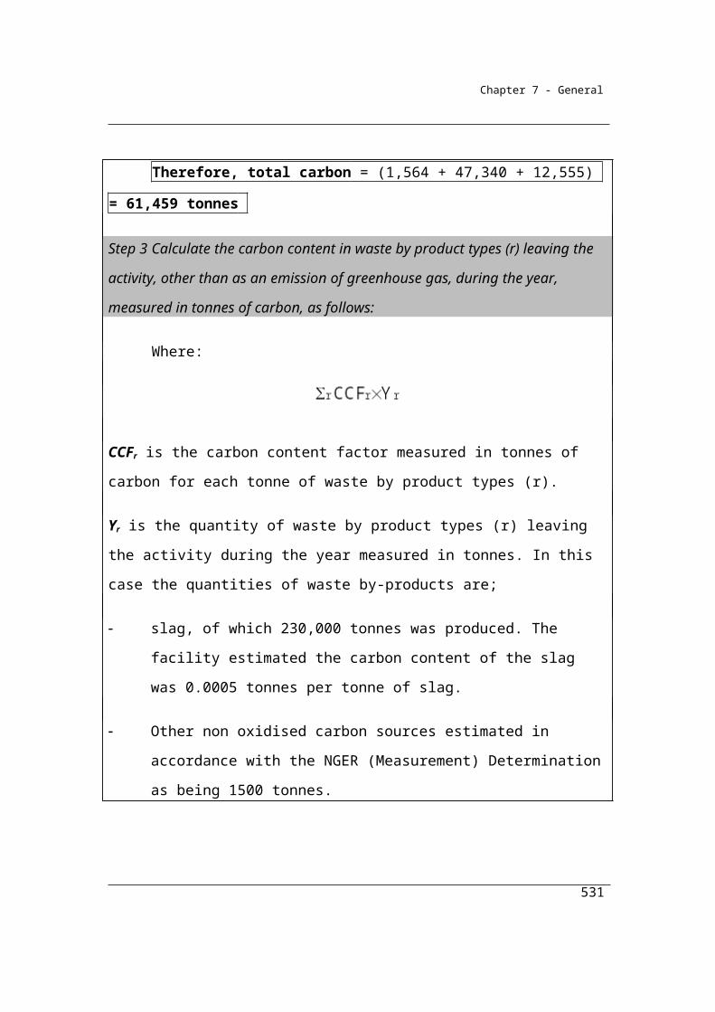
Chapter 7 - General
This approach minimises information requirements for the system and produces factors that are relatively easy to interpret and apply, and which are used to support a range of specific government programs and policies. Consistent adoption of these ‘physical’ state-based emission factors ensures the emissions generated in each state are fully accounted for by the end-users of the purchased electricity and double counting is avoided.
It is recognised that this approach does not serve all possible policy purposes and that alternative, more data-intensive approaches are possible. Reporters will be able to provide additional data on a voluntary basis on consumption of certain renewable products.
Background to Scope 2 factor estimates
The scope 2 emission factors reflect data that are based on:
on-grid activity only;
state-based activity;
annual financial year averages;
physical characteristics of the electricity supply and demand.
The estimated electricity emission factors have been aligned with the definitions used in The Greenhouse Gas Protocol: A Corporate Accounting and Reporting Standard of the World Resources Institute/World Business Council for Sustainable Development (the GHG Protocol).
The emission factor for scope 2 is defined in terms of energy sent out on the grid rather than energy delivered because this effectively ensures that end users of electricity are allocated only the scope 2 emissions attributable to the electricity they consume and not the scope 2 emissions attributable to electricity lost in transmission and distribution. The latter are allocated to the transmission and distribution network. This follows the GHG Protocol guidance that scope 2 emissions be reported by the organisation owning or controlling the plant or equipment where the electricity is consumed. Companies that own or control transmission and distribution networks report their transmission and distribution loss emissions under scope 2.
531
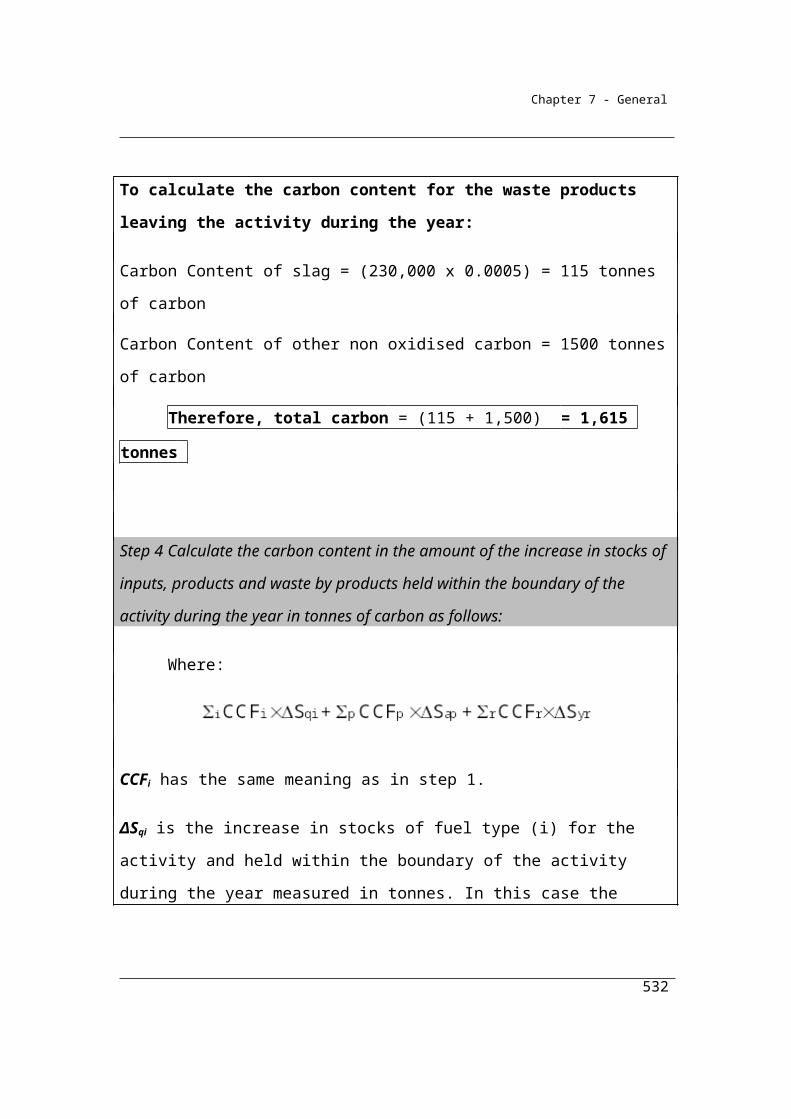
Chapter 7 - General
The emission factors are calculated as financial year averages based on electricity generation within each state and territory and take into account interstate electricity flows (where they exist) and the emissions attributable to those flows. To reduce volatility scope 2 emission factors are calculated as a three-year moving average.
Scope 2 emissions result from the generation of purchased electricity from each state’s electricity grid. The emission factor at generation (EFG scope2t
i) is used to calculate scope 2 emissions and is defined for state i and financial year t:
EFG scope2it=
Combustion emissions from electricity consumed from the grid in state i (CE¿t )
Electricity sent out consumed from the grid in state i (ESO¿t )
Where
‘combustion emissions from electricity consumed from the grid in state i’ (CE_Cti)
and ‘energy sent out consumed from the grid in state i’ (ESO_Cti) are defined in
terms of the state’s electricity grid generation, imports and exports as follows:
CE¿t=CE¿
t+∑j
(ESO¿t
ESO¿t ×CE¿
t )−∑k
( ESO¿t
ESO¿t ×CE¿
t )ESO¿
t=ESO¿t+∑
j
ESO¿t−∑
k
ESO¿t
where
CE_Pti is the total CO2-e emissions from fuel combustion at generation attributed to the electricity
generated/produced for the grid in state i in financial year t
CE_Ptj is the total CO2-e emissions from fuel combustion at generation attributed to the electricity
generated for the grid in state j in financial year t
ESO_Mtj,i is the imports of energy sent out from state j to state i in financial year t. Imports are
calculated from the interregional flows of electricity across the interconnectors published by the
National Electricity Market Management Company (NEMMCO)
532
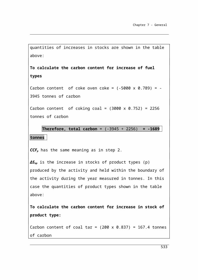
Chapter 7 - General
ESO_Xti,k is the exports of energy sent out from state i to state k in financial year t. Exports are
calculated from the inter-regional flows of electricity across the interconnectors published by
NEMMCO
ESO_Ptj is the total energy sent out on the grid that is generated within state j in financial year t
ESO_Pti is total energy sent out on the grid that is generated within state i in financial year t
The estimated ‘Scope 2’ emission factors for consumption of purchased electricity use data obtained under the National Greenhouse and Energy Reporting Act and is supplemented with data from the Australian Energy Market Operator, ABARE and the Energy Supply Association of Australia. Emission estimates are taken from the National Greenhouse Accounts. Further detail on the approach to calculating electricity emission estimates is available in the National Inventory Report 2014.
533
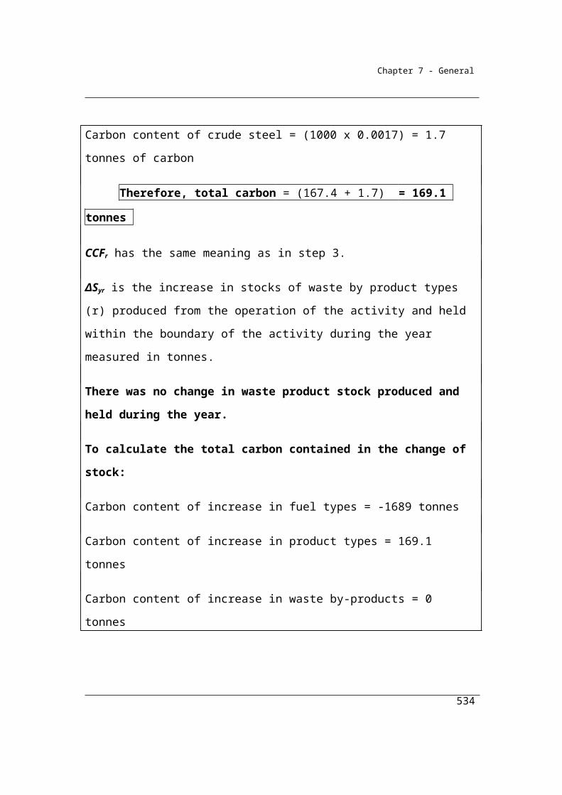
Chapter 8 - Assessment of uncertainty
Chapter 8—Assessment of uncertaintyProposed changes to the NGER Regulations will only require reporters with emissions of more than 25 kilotonnes of CO2-e from the combustion of a fuel type, or a source other than fuel combustion to calculate and report the statistical uncertainty associated with their scope 1 emissions. Sources are defined in section 1.10 of the Measurement Determination and fuel types are set out in Schedule 1 of the NGER Regulations.
Part 8.1—Preliminary
The GHG Protocol guidance on uncertainty assessment in GHG inventories and calculating statistical parameter uncertainty (September 2003) v1.0 (the uncertainty protocol) is the source document for the methodology of calculating uncertainty under NGERS. It is referred to in this chapter as the uncertainty protocol.
This document is produced by the World Resources Institute and the World Business Council on Sustainable Development and is available at http://www.ghgprotocol.org/calculation-tools/all-tools and has detailed information about the calculation of uncertainty in greenhouse gas inventories.
There are a number of different sources of uncertainty identified in the uncertainty protocol – however corporations are only asked to estimate the statistical uncertainty. This type of uncertainty results from natural variations (for example, random human errors in the measurement process and fluctuations in measurement equipment). More information is provided in the uncertainty protocol.
Proposed ammendments to the NGER Regulations will require only reporters with the largest sources of emissions (25,000 tonnes of CO2-e or over) to calculate and report the statistical uncertainty associated with emissions reporting.
8.1 Outline of Chapter
(1) This Chapter sets out rules about how uncertainty is to be assessed in working out estimates of scope 1 emissions for a source, a facility and a registered corporation.
534
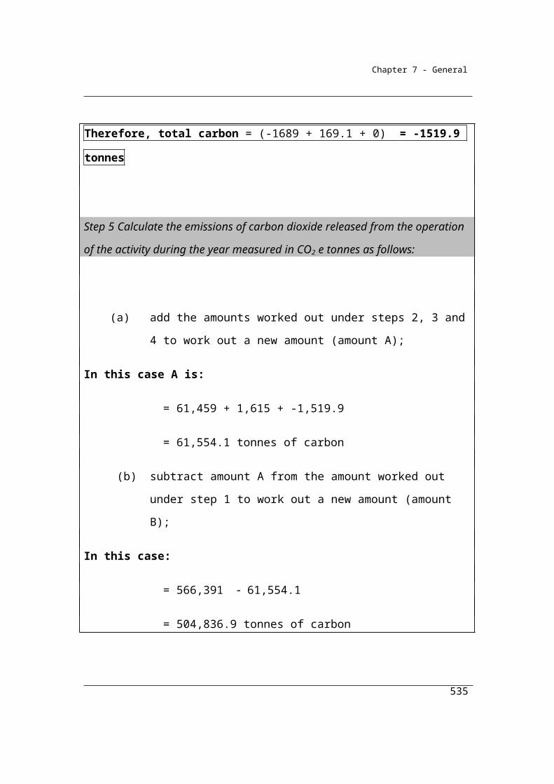
Chapter 8 - Assessment of uncertainty
(2) Part 8.2 sets out general rules for assessing uncertainty of scope 1 emissions estimates.
(3) Part 8.3 sets out how to assess the uncertainty of estimates of scope 1 emissions that have been estimated using method 1.
(4) Part 8.4 sets out how to assess the uncertainty of estimates of scope 1 emissions that have been estimated using method 2, 3 or 4.
(5) Emissions estimates for a source that are calculated using method 1, 2 or 3 are a function of a number of parameters. The uncertainty of the emissions estimates consists of the uncertainty associated with each of these parameters, which may include one or more of the following parameters:
(a) energy content factor;(b) emissions factor;(c) activity data.
Note: In the case of fuel combustion, activity data refers to the quantity of fuel combusted. In the case of industrial processes, activity data refers to the quantity of product consumed or produced, as appropriate.
(6) Estimates of emissions need only provide for statistical uncertainty.Note: The uncertainty protocol provides information about the assessment of
uncertainty.
535
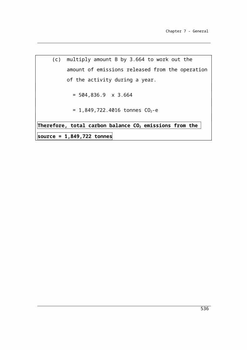
Chapter 8 - Assessment of uncertainty
Part 8.2—General rules for assessing uncertainty
Note that there is a difference in meaning between the common usage of the word ‘confidence’ and its statistical usage in relation to ‘95% confidence interval’. In natural science and technical experiments it is often standard practice to estimate uncertainty at the 95% confidence interval. The ‘confidence interval’ is defined by a probability value (in this case a probability of 95%) and confidence limits on either side of the mean value.
This means that the uncertainty level (the +/- percentages – otherwise known as the confidence limits) is to be calculated so that there is a 95% probability that the true value of the estimate is encompassed by the estimated uncertainty levels (the confidence limits). For example, an emission estimate of 100kt +/- 10% at the 95% confidence interval means that the true value lies between 90kt and 110kt with a probability of 95%.
8.2 Range for emission estimates
Uncertainty must be assessed so that the range for an emissions estimate encompasses the actual amount of the emissions with 95% confidence.
8.3 Uncertainty to be assessed having regard to all facilities
The calculation of uncertainty for a registered corporation should take into account the uncertainty associated with all the sources of emissions reported by the corporation. The uncertainty associated with each emission source is to be aggregated to the “subtotal” of uncertainty at the facility level and the uncertainty associated with each facility if to be aggregated to the “total” of uncertainty at the corporation level.
In the calculation of uncertainty, it is important that the corporation calculates their uncertainty at the same level of disaggregation to which the emission estimate was calculated. For example, if a facility uses multiple types and qualities of a fuel (e.g. different types of coals) for which it has data on, and the emission calculation incorporates the data on each different fuel types, then the uncertainty calculation should also be performed at the same level of disaggregation. In other words, the
536
Chapter 8 - Assessment of uncertainty
uncertainty calculation should incorporate uncertainty data on the different fuel types at the same level of detail that was performed in the emission calculation.
(1) Uncertainty of estimates of scope 1 emissions for a registered corporation must be assessed in accordance with Part 8.3 or with the uncertainty protocol, as appropriate, having regard to all of the facilities under the operational control of the corporation.
(2) For corporations that have multiple sources of scope 1 emissions that are estimated using a variety of method 1, 2, 3 or 4, the uncertainty associated with the emissions must be aggregated in accordance with section 8 of the uncertainty protocol.
537
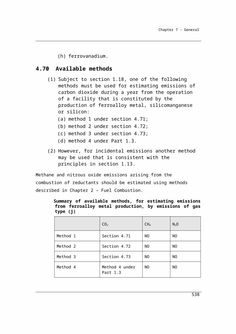
Chapter 8 - Assessment of uncertainty
Part 8.3—How to assess uncertainty when using method 1
8.4 Purpose of Part
This Part sets out how to assess uncertainty of scope 1 emissions if method 1 is used to estimate:
(a) scope 1 emissions for a source; and(b) scope 1 emissions for a facility; and(c) scope 1 emissions for a registered corporation.
8.5 General rules about uncertainty estimates for emissions estimates using method 1
(1) The total uncertainty of scope 1 emissions estimates for a source in relation to a registered corporation is to be worked out by aggregating, as applicable, the uncertainty of the emissions factor, the energy content factor and the activity data for the source in accordance with the formula in section 8.11.Note: This is generally referred to as the aggregated uncertainty for the source.
(2) The total uncertainty of scope 1 emissions estimates for a facility is to be worked out by aggregating the total uncertainty for each source associated with the facility in accordance with the formula in section 8.12.Note: This is generally referred to as the subtotal uncertainty for the facility.
(3) The total uncertainty of scope 1 emissions estimates for a registered corporation is to be worked out by aggregating the total uncertainty for each facility under the operational control of the corporation in accordance with the formula in section 8.13.Note: This is generally referred to as the total uncertainty for the corporation.
8.6 Assessment of uncertainty for estimates of carbon dioxide emissions from combustion of fuels
(1) In assessing uncertainty of the estimates of carbon dioxide emissions estimated using method 1 for a source that involves the combustion of a fuel, the assessment must include the statistical uncertainty associated with the following parameters:
538
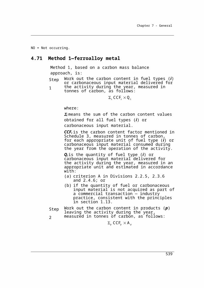
Chapter 8 - Assessment of uncertainty
(a) the energy content factor of the fuel (as specified in column 3 of the following table or as worked out in accordance with item 1, 2 or 3 of section 7 of the uncertainty protocol);
(b) the carbon dioxide emission factor of the fuel (as specified in column 4 of the following table or as worked out in accordance with item 1, 2 or 3 of section 7 of the uncertainty protocol);
(c) the quantity of fuel combusted (as worked out in accordance with subsection (3) or as worked out in accordance with item 1, 2 or 3 of section 7 of the uncertainty protocol).
Item Fuel Combusted Energy content uncertainty level (%)
Carbon dioxide emission factor uncertainty level (%)
1 Bituminous coal 28 51A Sub-bituminous coal 28 51B Anthracite 28 52 Brown coal 50 123 Coking coal 12 74 Coal briquettes 40 115 Coal coke 9 116 Coal tar 50 177 Solid fossil fuels other than those mentioned in items 1
to 550 15
8 Industrial materials and tyres that are derived from fossil fuels, if recycled and combusted to produce heat or electricity
50 26
9 Non-biomass municipal materials, if recycled and combusted to produce heat or electricity
50 26
10 Dry wood 50 NA11 Green and air-dried wood 50 NA12 Sulphite lyes 50 NA13 Bagasse 50 NA14 Biomass municipal and industrial materials, if recycled
and combusted to produce heat or energy50 NA
15 Charcoal 50 NA16 Primary solid biomass fuels other than those
mentioned in items 10 to 1550 NA
539

Chapter 8 - Assessment of uncertainty
Item Fuel Combusted Energy content uncertainty level (%)
Carbon dioxide emission factor uncertainty level (%)
17 Natural gas if distributed in a pipeline 4 418 Coal seam methane that is captured for combustion 4 419 Coal mine waste gas that is captured for combustion 4 420 Compressed natural gas that has reverted to standard
conditions4 4
21 Unprocessed natural gas 4 422 Ethane 4 1023 Coke oven gas 50 1924 Blast furnace gas 50 1725 Town gas 4 426 Liquefied natural gas 7 427 Gaseous fossil fuels other than those mentioned in
items 17 to 2650 10
28 Landfill biogas that is captured for combustion (methane only)
50 NA
29 Sludge biogas that is captured for combustion (methane only)
50 NA
30 A biogas that is captured for combustion, other than those mentioned in items 28 and 29 (methane only)
50 NA
31 Petroleum based oils (other than petroleum based oils used as fuel)
11 2
32 Petroleum based greases 11 233 Crude oil including crude oil condensates 6 334 Other natural gas liquids 7 935 Gasoline (other than for use as fuel in an aircraft) 3 436 Gasoline for use as fuel in an aircraft 3 437 Kerosene (other than for use as fuel in an aircraft) 3 238 Kerosene for use as fuel in an aircraft 3 339 Heating oil 5 240 Diesel oil 2 241 Fuel oil 2 242 Liquefied aromatic hydrocarbons 5 243 Solvents if mineral turpentine or white spirits 18 2
540
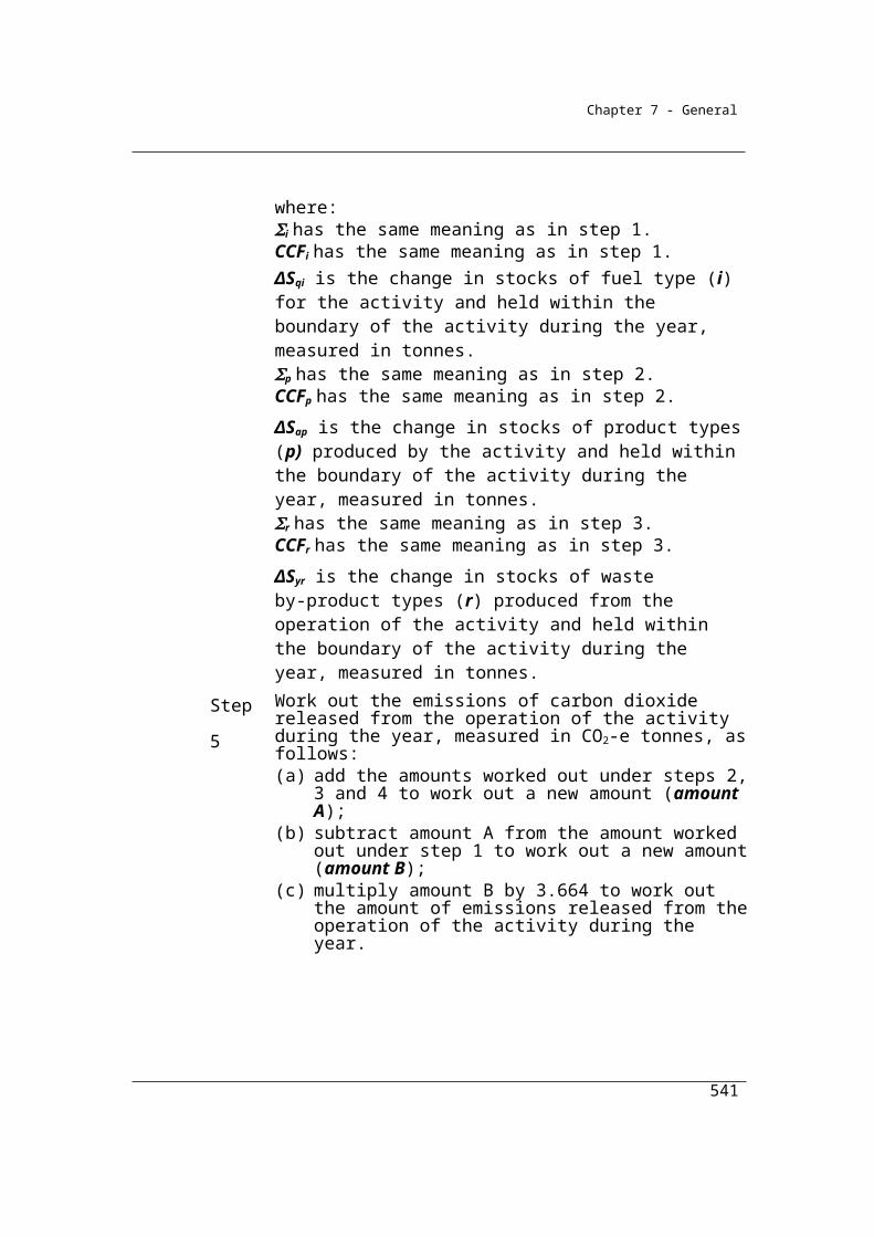
Chapter 8 - Assessment of uncertainty
Item Fuel Combusted Energy content uncertainty level (%)
Carbon dioxide emission factor uncertainty level (%)
44 Liquid petroleum gas 8 345 Naphtha 5 546 Petroleum coke 19 1747 Refinery gas and liquids 19 1848 Refinery coke 19 1749 Petroleum based products other than:
(a) petroleum based oils and petroleum based greases mentioned in items 31 and 32; and
(b) the petroleum based products mentioned in items 33 to 48
18 2
50 Biodiesel 50 NA51 Ethanol for use as a fuel in an internal combustion
engine50 NA
52 Biofuels other than those mentioned in items 50 and 51 50 NA
(2) In the table in subsection (1), NA means not applicable.
(3) For a fuel type specified in column 2 of an item of the following table:(a) column 3 for the item sets out the uncertainty level for the estimated
quantities of fuel combusted using criterion A in Chapter 2; and (b) column 4 for the item sets out the uncertainty level for the estimated
quantities of fuel combusted using criterion AA in Chapter 2; and(c) column 5 for the item sets out the uncertainty level for the estimated
quantities of fuel combusted using criterion AAA in Chapter 2; and(d) column 6 for the item sets out the uncertainty level for the estimated
quantities of fuel combusted using criterion BBB in Chapter 2.Note: Division 2.2.5 sets out the relevant criteria for solid fuels; Division 2.3.6 sets
out the relevant criteria for gaseous fuels; and Division 2.4.6 sets out the relevant criteria for liquid fuels.
Item Fuel type Uncertainty levels for quantities of fuel combusted (%)Criterion used for estimation of quantity of fuel combusted A AA AAA BBB
541
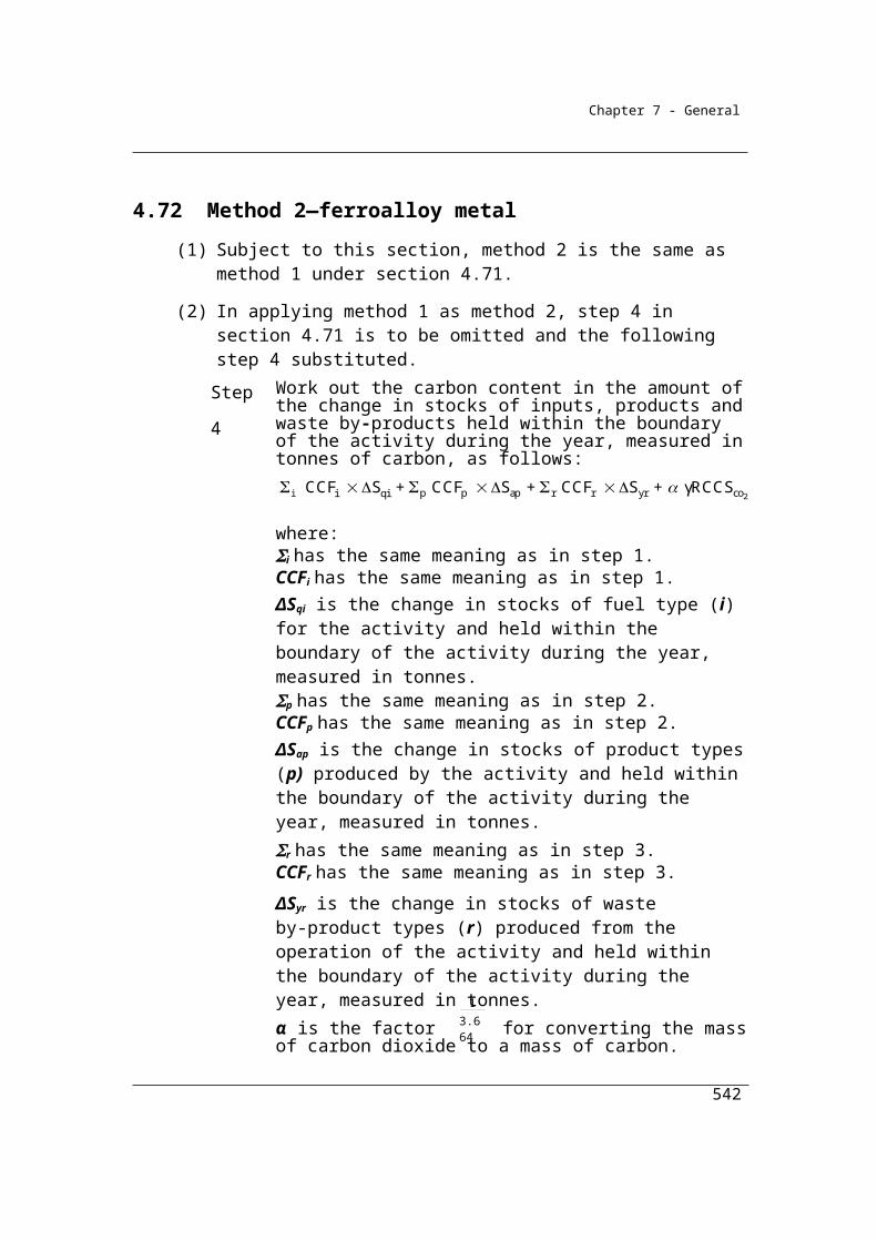
Chapter 8 - Assessment of uncertainty
1 Solid fuel 2.5 2.5 1.5 7.52 Liquid fuel 1.5 1.5 1.5 7.53 Gaseous fuel 1.5 1.5 1.5 7.5
8.7 Assessment of uncertainty for estimates of methane and nitrous oxide emissions from combustion of fuels
(1) In assessing uncertainty of the estimates of methane and nitrous oxide emissions estimated using method 1 for a source that involves the combustion of a fuel specified in column 2 of an item in the table in subsection 8.6(1):
(a) the uncertainty level of the energy content factor is:(i) as specified in column 3 for the item; or
(ii) as worked out in accordance with section 7 of the uncertainty protocol; and
(b) the uncertainty level of the emissions factor is:(i) 50%; or
(ii) as worked out in accordance with section 7 of the uncertainty protocol.
(2) In assessing uncertainty of the estimates of methane and nitrous oxide emissions estimated using method 1 for a source that involves the combustion of a fuel type specified in column 2 of an item in the table in subsection 8.6(3):
(a) column 3 for the item sets out the uncertainty level for the estimated quantities of fuel combusted using criterion A in Chapter 2; and
(b) column 4 for the item sets out the uncertainty level for the estimated quantities of fuel combusted using criterion AA in Chapter 2; and
(c) column 5 for the item sets out the uncertainty level for the estimated quantities of fuel combusted using criterion AAA in Chapter 2; and
(d) column 6 for the item sets out the uncertainty level for the estimated quantities of fuel combusted using criterion BBB in Chapter 2.
Note: Division 2.2.5 sets out the relevant criteria for solid fuels; Division 2.3.6 sets out the relevant criteria for gaseous fuels; and Division 2.4.6 sets out the relevant criteria for liquid fuels.
8.8 Assessment of uncertainty for estimates of fugitive emissions
Note that the uncertainty levels in this section are the aggregate uncertainty levels for the source and may be used by substituting directly into the aggregation equations for facilities and the corporation in sections 8.12 and 8.13 as appropriate. Default
542

Chapter 8 - Assessment of uncertainty
individual parameter uncertainties have not been provided for fugitive emissions that are calculated under method 1 and hence the parameter aggregation equation in section 8.11 is not applicable when these defaults are used.
The aggregated uncertainty of the estimates of fugitive emissions estimated using method 1 for a source mentioned in column 2 of an item of the following table is:
(a) as specified in column 3 for the item; or(b) as worked out in accordance with the uncertainty protocol.
Item Sources Aggregated uncertainty level (%)
1 Underground mines 502 Open cut mines 503 Decommissioned underground mines 504 Oil or gas exploration 505 Crude oil production 506 Crude oil transport 507 Crude oil refining 508 Natural gas production or processing (other than emissions that are
flared)50
9 Natural gas transmission 5010 Natural gas distribution 5011 Natural gas production or processing—flaring 25
8.9 Assessment of uncertainty for estimates of emissions from industrial process sources
(1) In assessing uncertainty of the estimates of emissions estimated using method 1 for the industrial process sources mentioned in column 2 of an item of the following table, the assessment must include the uncertainty level for the emission factor and activity data associated with the source:
(a) as specified:(i) for the emission factor—in column 3 for the item; and
(ii) for the activity data—in column 4 for the item; or(b) as worked out in accordance with the uncertainty protocol.
543
Chapter 8 - Assessment of uncertainty
Item Industrial process sources Emission factor uncertainty level (%)
Activity data uncertainty (%)
1 Cement clinker production 6 1.52 Lime production 6 1.53 Soda ash use 5 1.54 Use of carbonates for the production of a product other
than cement clinker, lime or soda ash5 1.5
5 Nitric acid production 40 1.56 Adipic acid production 10 1.57 Aluminium (carbon anode consumption) 5 18 Aluminium production (perfluoronated carbon
compound emissions)6 1
(2) In assessing uncertainty of the estimates of emissions estimated using method 1 for industrial process sources mentioned in column 2 of an item of the following table, column 3 for the item sets out the aggregated uncertainty level associated with the source.
For aluminium production the uncertainty for estimates of emissions may be assessed using the information provided in Chapter 4 of the 2006 IPCC Guidelines for National Greenhouse Gas Inventories (Volume 3).
Item Industrial process sources Aggregated uncertainty level (%)
1 Emissions of hydrofluorocarbons and sulphur hexafluoride gas 30
Note that the above uncertainty level is the aggregate uncertainty level for the source (Emissions of hydrofluorocarbons and sulphur hexafluoride gas) and may be used by substituting directly into the aggregation equations for facilities and the corporation in sections 8.12 and 8.13 as appropriate. Default individual parameter uncertainties have not been provided for this emission source calculated under method 1 and hence the parameter aggregation equation in section 8.11 is not applicable when the above default is used.
544

Chapter 8 - Assessment of uncertainty
(3) The uncertainty of estimates of emissions for industrial process sources that are not mentioned in subsections (1) or (2) must be assessed:
(a) if the industrial process source involves the combustion of fuel—in accordance with:(i) for carbon dioxide emissions—section 8.6; and
(ii) for methane and nitrous oxide emissions—section 8.7; and(b) if the industrial process source does not involve the combustion of
fuel—in accordance with the uncertainty protocol.
8.10 Assessment of uncertainty for estimates of emissions from waste
Note that the uncertainty levels in this section are the aggregate uncertainty levels for the source and may be used by substituting directly into the aggregation equations for facilities and the corporation in sections 8.12 and 8.13 as appropriate. Default individual parameter uncertainties have not been provided for waste sector emissions calculated under method 1 and hence the parameter aggregation equation in section 8.11 is not applicable when these defaults are used.
In assessing uncertainty of the estimates of emissions from waste estimated using method 1 for the activities mentioned in column 2 of an item of the following table, the assessment must include the aggregated uncertainty level:
(a) as specified in column 3 for the item; or(b) as worked out in accordance with the uncertainty protocol.
Item ActivitiesAggregated uncertainty level (%)
1 Solid waste disposal on land 352 Wastewater handling (industrial) 653 Wastewater handling (domestic or
commercial)40
4 Waste incineration 40
8.11 Assessing uncertainty of emissions estimates for a source by aggregating parameter uncertainties
The technique used in this chapter for aggregating the uncertainty is known as first order error propagation. Further information and guidance is given in the uncertainty protocol and its reference documents. There are four key assumptions that are made
545

Chapter 8 - Assessment of uncertainty
when this technique is used and should be considered when applying these formulas which are:
1. The error in each parameter is normally distributed
2. There are no biases in the estimator function, (i.e. the estimated value is the mean value)
3. The estimated parameters are uncorrelated
4. Individual uncertainties in each parameter must be less than 60% of the mean
In most cases it will be reasonable to assume that the above conditions are satisfied and that any uncertainty calculation will be reasonable.
(1) For subsection 8.5(1) and subject to subsections (2) and (3), in assessing uncertainty of the estimates of scope 1 emissions that are estimated using method 1 for a source, the aggregated uncertainty for emissions from the source is to be worked out in accordance with the following formula:
2 2 2 D A B C
where:
D is the aggregated percentage uncertainty for the emission source.
A is the uncertainty associated with the emission factor for the source, expressed as a percentage.
B is the uncertainty associated with the energy content factor for the source, expressed as a percentage.
C is the uncertainty associated with the activity data for the source, expressed as a percentage.
(2) If an assessment of uncertainty of emissions for the source does not require the use of emissions factor uncertainty, energy content factor uncertainty or activity data uncertainty, then A, B or C, as appropriate, in the formula in subsection (1) is taken to be zero.Example: If energy content factor uncertainty is not required for an industrial process
source, then B would be taken to be zero in the formula in subsection (1) when assessing the aggregated uncertainty for the source.
(3) Subsection (1) does not apply to:
546
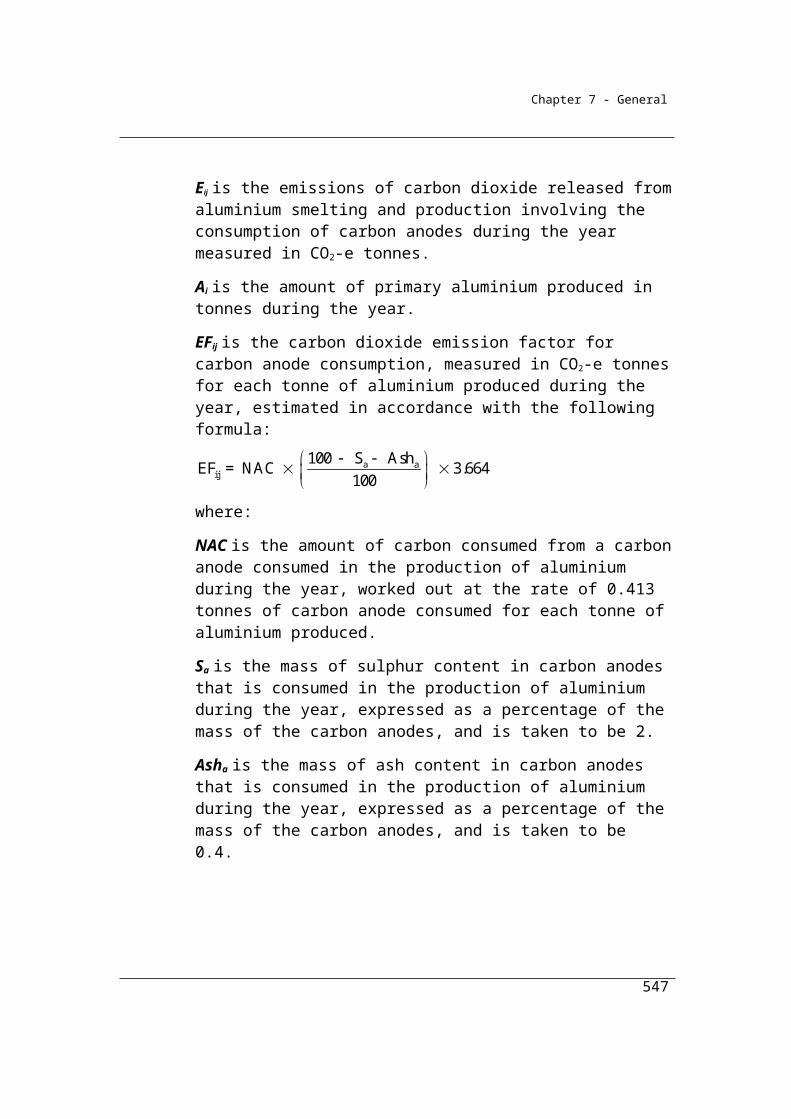
Chapter 8 - Assessment of uncertainty
(a) estimates of fugitive emissions that are assessed by using the aggregated uncertainty level in column 3 of the table in section 8.8; or
(b) estimates of emissions from industrial processes that are assessed by using the aggregated uncertainty level in column 3 of the table in subsection 8.9(2); or
(c) estimates of emissions from waste activities that are assessed by using the aggregated uncertainty level in column 3 of the table in section 8.10.
8.12 Assessing uncertainty of emissions estimates for a facility
For subsection 8.5(2), in assessing uncertainty of estimates of scope 1 emissions for a facility that are estimated using method 1, the following formula must be used to aggregate the uncertainty of emissions estimates for all the sources associated with the facility:
2 2 21 1 2 2
1 2
( ) ( ) ... ( )
...
n nsubtotal
n
D E D E D EU
E E E
where:
Usubtotal is the percentage uncertainty for the subtotal of emissions for the facility.
D1 → Dn are the percentage uncertainties associated with each emission estimate (E1 → En) for the source.
E1 → En are the estimated emissions from each source associated with the facility measured in CO2-e tonnes.
8.13 Assessing uncertainty of emissions estimates for a registered corporation
For subsection 8.5(3), in assessing uncertainty of estimates of scope 1 emissions for a registered corporation that are estimated using method 1, the following formula must be used to aggregate the uncertainty of emissions estimates for all the facilities under the operational control of the corporation:
2 2 21 1 2 2 n n
1 2 ntotal
± (F G ) + (F G ) + ... + (F G )U =
G + G + ... + G× × ×
where:
547
Chapter 8 - Assessment of uncertainty
Utotal is the percentage uncertainty for the total emissions for the registered corporation.
F1 → Fn are the percentage uncertainties associated with each emission estimate (G1 → Gn) for the facility.
G1 → Gn are the estimated emissions from each facility under the operational control of the corporation measured in CO2-e tonnes.
Example
A corporation has two facilities, each of which has two sources of emissions. The first facility combusts diesel oil and black coal, while the second facility combusts natural gas and gasoline. The calculation of the carbon dioxide equivalent emissions using method 1 and the uncertainty of this (method 1) emission estimate for the corporation are shown in the table below.
For facility 1, an emission source is the combustion of diesel oil. The emissions for this source are estimated by method 1 to be 2,671.1 CO2-e tonnes under section 2.41 as shown in the table. Since method 1 has been used to calculate the emissions, the default uncertainty levels from section 8.6 for the parameters used in the emissions calculation are applicable in calculating the uncertainty, which are 1.5% for quantity of fuel combusted (measured in kL), 2% for the energy content factor (measured in GJ/kL), and 2% for the emission factor (kg CO2-e/GJ).
The aggregated uncertainty for this method 1 emission estimate (combustion of diesel oil) is calculated using the equation in section 8.11 as follows:
√1.5 %2+2 %2+2 %2=3.2 %
Therefore, the aggregate uncertainty for this source is +/- 3.2%. Similar calculations are performed for the uncertainty of the emissions estimate for the second source (combustion of black coal) for facility 1, to yield an uncertainty of 28.6%.
As shown in the table, the carbon dioxide emissions for the second source in facility 1 are estimated under method 1 to be 11,907.0 tonnes CO2e which makes a subtotal of carbon dioxide emissions of 14,578.2 CO2-e tonnes for facility 1. Then the subtotal uncertainty for facility 1 is calculated using the formula in section 8.12 as shown below:
548
Chapter 8 - Assessment of uncertainty
√(3.2 %×2,671.1)2+(28.6 %× 11,907.0)2
14,578.2=23.3 %
Therefore, the subtotal uncertainty of the carbon dioxide emissions for facility 1 is +/- 23.3%. Similar calculations are performed for facility 2, and the results are indicated in the table below, with the carbon dioxide emissions estimate being 24,952.9 CO2-e tonnes with an uncertainty of +/- 4.5%.
For calculating the total uncertainty for the corporation, use the formula in 8.13, as shown below:
√(23.3 %×14,578.2)2+(4.5 %×24,952.9)2
39,531.1=9.1 %
Similar calculations are then performed for Methane and Nitrous Oxide using the default uncertainties from section 8.7. The total uncertainty for CO2-e is then calculated and shown in the table below. Therefore the total uncertainty of the carbon dioxide equivalent emissions estimated under method 1 for the corporation is +/- 9.0/%. With the total emissions estimate under method 1 being 39,660.7 kg CO2-e.
Emissions / UncertaintyActivity
data
Energy Content
Factor
Emission
FactorEmission
Emission Data Source
As
measured
- Chapter
2
Schedule 1 Schedule 1
Calculated
under
Chapter 2
Emission Calculation Units kL, t, m3
GJ/kL, GJ/t,
GJ/m3 kg CO2-e/GJ CO2e t
Facility 1
Combustion of Diesel Oil 1,000 38.6 69.2 2,671
549

Chapter 8 - Assessment of uncertainty
Uncertainty level 1.5% 2.0% 2.0% 3.2%
Source of Uncertainty
Assessment
Section
8.6 Section 8.6 Section 8.6 Section 8.11
Combustion of Black Coal 5,000 27 88.2 11,907
Uncertainty level 2.5% 28.0% 5.0% 28.6%
Source of Uncertainty
Assessment
Section
8.6 Section 8.6 Section 8.6 Section 8.11
Facility 1 Subtotal 14,578
Uncertainty level 23.3%
Source of Uncertainty Assessment Section 8.12
Facility 2
Combustion of Natural
Gas
9,000,00
0 0.0393 51.2 18,109
Uncertainty level 1.5% 4.0% 4.0% 5.9%
Source of Uncertainty
Assessment
Section
8.6 Section 8.6 Section 8.6 Section 8.11
Combustion of Gasoline 3,000 34.2 66.7 6,843
Uncertainty level 1.5% 3.0% 4.0% 5.2%
Source of Uncertainty
Assessment
Section
8.6 Section 8.6 Section 8.6 Section 8.11
Facility 2 Subtotal 24,953
550

Chapter 8 - Assessment of uncertainty
Uncertainty level 4.5%
Source of Uncertainty Assessment Section 8.12
Corporation Total - CO2 emissions 39,531
Uncertainty level 9.1%
Source of Uncertainty Assessment Section 8.13
Corporation Total CH4 and N2O emissions - kg CO2-e 130
Uncertainty level 22.1%
Source of Uncertainty Assessment - Similar to CO2 Calculations
Corporation Total CO2-e emissions 39,661
Uncertainty level 9.0%
Source of Uncertainty Assessment Section 8.13
551
Chapter 8 - Assessment of uncertainty
Part 8.4—How to assess uncertainty levels when using method 2, 3 or 4
8.14 Purpose of Part
This Part sets out rules that apply in the assessment of uncertainty of scope 1 emissions from the operation of a facility that are estimated using method 2, 3 or 4.
8.15 Rules for assessment of uncertainty using method 2, 3 or 4
(1) Subject to this section:(a) the uncertainty of the following must be assessed in accordance with
the uncertainty protocol:(i) scope 1 emissions estimates that are estimated using method 2,
3 or 4;(ii) scope 1 fugitive emissions estimates for open cut coal mines
that are estimated using method 4; and(b) the uncertainty of scope 1 fugitive emissions estimates for open cut
coal mines that are estimated using method 2 or 3 must be:(i) assessed in accordance with the uncertainty protocol; and
(ii) estimated using the method included in section 5 of the ACARP Guidelines.
(2) Item 4 of Part 7 of the uncertainty protocol must not be used when emissions are estimated using method 2, 3 or 4.
(2A) Subsection (2) does not apply to assessing the uncertainty of scope 1 fugitive emissions estimates for open cut coal mines using method 2, 3 or 4.
(3) Estimates need only provide for statistical uncertainties in accordance with the uncertainty protocol.
The technique described in the GHG uncertainty protocol to be applied when methods 2, 3 and 4 are used to estimate emissions is similar to the technique outlined for the calculation of uncertainty for method 1. The key difference is that the parameter uncertainties should be estimated directly rather than taken from the
552
Chapter 8 - Assessment of uncertainty
default tables in sections 8.6 to 8.10. Techniques for estimating these parameters are given in section 7 of the uncertainty protocol. Also, further guidance and discussion on calculation of uncertainty is given in uncertainty protocol.
Generally, the uncertainties estimated under the higher order methods 2, 3 and 4 are likely to be lower than those calculated under method 1, indicating that the emission estimate using the higher order methods is more accurate than that calculated under method 1. The main reason for this is that in method 1 default energy content factors are used and there is significant uncertainty around these defaults, particularly for solid fuels such as coal (note that electricity generators are required to use methods 2 or higher for emissions estimates). Higher order methods of analysis require direct analysis of the fuel giving a much more accurate estimation of the carbon content of fuels and hence the emissions.
Example
Estimates of emissions and uncertainty for the same corporation (combusting the same estimated fuel quantities) are now given using method 2. The parameters used in the method 2 emissions calculation are different to that of method 1 and the source of parameter uncertainty is estimated by the corporation (rather than taken from tables). Note that calculations for aggregating uncertainties are similar to those for method 1 and guidance is given in the uncertainty protocol.
Note that guidance on estimating the parameter uncertainties is given in section 7 of the GHG protocol, (although item 4 in the list of available methods in section 7 is not to be used).
553
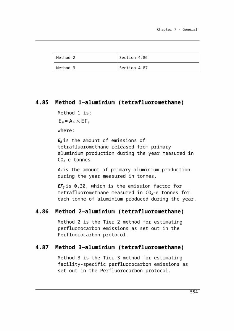
Chapter 8 - Assessment of uncertainty
Facility 1
Combustion of Diesel
Oil
Q - kL % carbon
Fuel
densit
y kg/kL
EC OF Constant EFEmission
(tonnes)
1,000 85.2 850 38.6 0.99 3.664 68.1 2,627
Uncertainty 1.5% 1.5% 1.0% NA 0.0% NA 1.8% 2.3%
Source of Uncertainty a b c d e f g g
Combustion of Black
Coal
Q - t % carbon EC OF Constant EF Emission
5,000 62.2 NA 27 0.98 3.664 82.7 11,167
Uncertainty 2.5% 3.0% NA NA 0.0% NA 3.0% 3.9%
Source of Uncertainty a b d e f g g
Facility 1 Subtotal 13,794
Uncertainty 3.2%
Source of Uncertainty h
Facility 2
Combustion of
Natural Gas
Q - m3Gas
Compositio
n
Fuel
densit
y
kg/m3
EC OF Constant EF Emission
9,000,000 NA 0.74 0.0393
0.99
5 2.743 51.4 18,178
Uncertainty 1.5% 3.0% 1.0% NA 0.0% NA 3.2% 3.5%
Source of Uncertainty a i c d e f g G
554
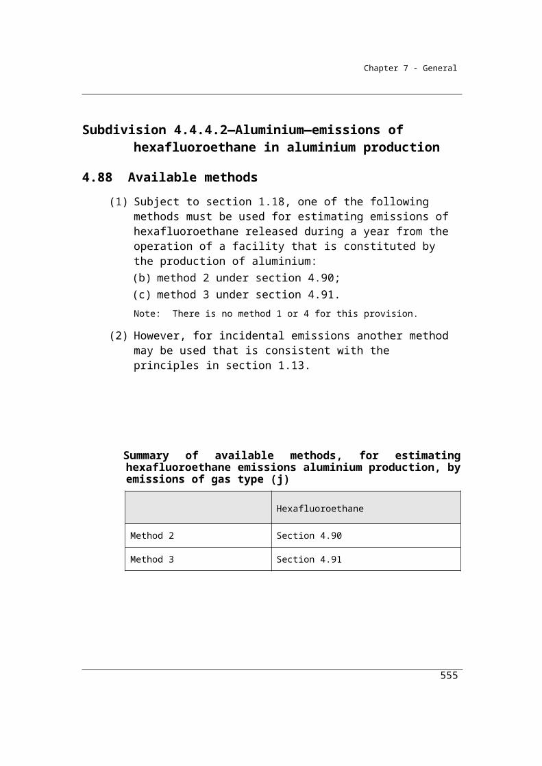
Chapter 8 - Assessment of uncertainty
Combustion of
Gasoline
Q - kL % carbon
Fuel
densit
y kg/kL
EC OF Constant EF Emission
3,000 85.2 720 34.2 0.99 3.664 65.1 6,676
Uncertainty 1.5% 2.0% 1.0% NA 0.0% NA 2.2% 2.7%
Source of Uncertainty a b c d e f g G
Facility 2 Subtotal 24,854
Uncertainty 2.7%
Source of Uncertainty H
Corporation Total - CO2 emissions 38,648
Uncertainty 2.1%
Source of Uncertainty H
Corporation Total CH4 and N20 emissions - kg CO2-e (using method 1) 130
Uncertainty level 22.1%
Source of Uncertainty Assessment - Similar to CO2 Calculations for method 1
Corporation Total CO2-e emissions 38,778
Uncertainty level 2.0%
Source of Uncertainty Assessment H
Notes:
555
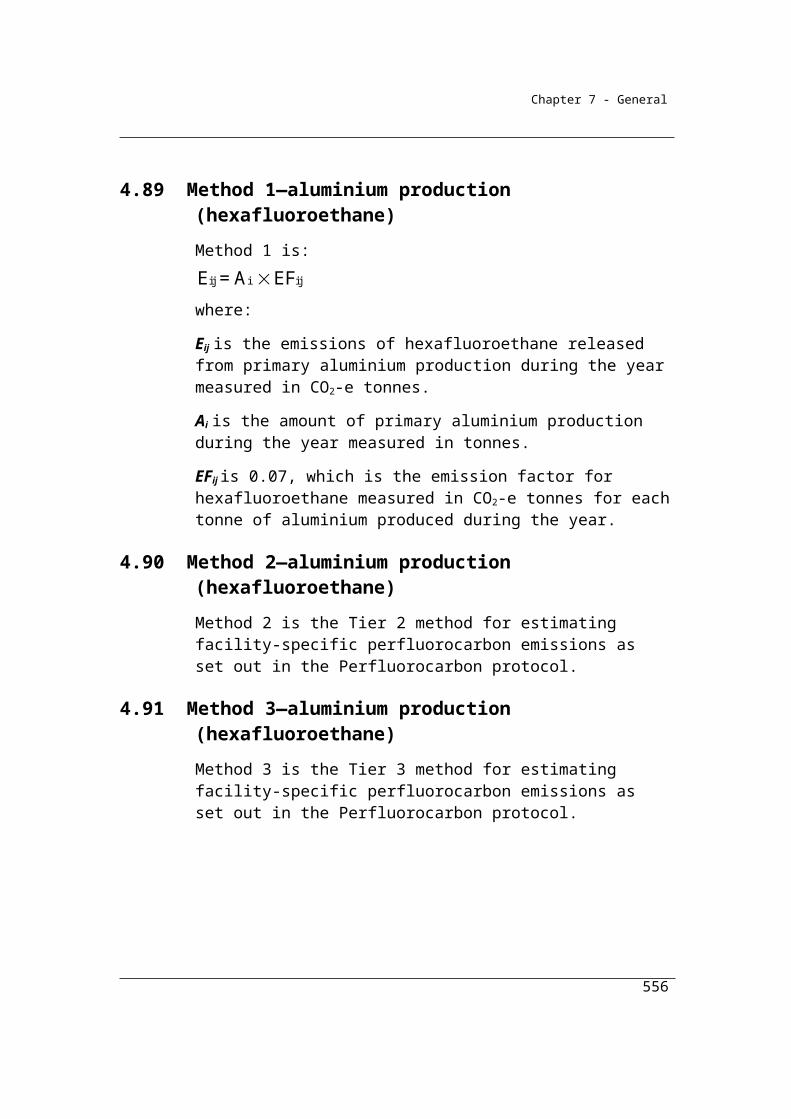
Chapter 8 - Assessment of uncertainty
a Uncertainty potentially assessed on fuel measurement instrument precision. Fuel use from stockpiles, for example, may
generate larger uncertainties which may need to be considered.
b Sampling and analysis uncertainty, either through instrument precision or other statistical method
c Uncertainty associated with fuel density from sampling and analysis
d Uncertainty associated with energy content not relevant to method 2 since energy content factor falls out in calculation of
emissions
e Uncertainty associated with the oxidation factor assumed to be zero in these cases though may be incorporated in an
uncertainty calculation where considered significant
f Uncertainty associated with these molecular mass constants is not statistical uncertainty as defined by the uncertainty
protocol and hence is not incorporated
g This uncertainty is aggregated using the method in section 7 of the uncertainty protocol
h This uncertainty is aggregated using the method in section 8 of the uncertainty protocol
i Sampling and analysis uncertainty of gas composition (assumed to be 100% methane in the emission calculation)
556
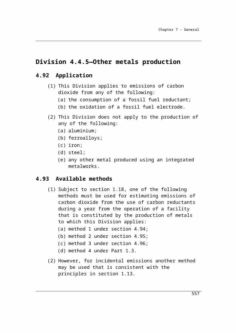
Appendices
Appendix A: Schedule 3 Carbon content factors(subsection 2.61 (1), sections 3.65, 4.66 and subsections 4.67 (2) and 4.68 (2))
Note 1 Under the 2006 IPCC Guidelines, the emission factor for CO2 released from combustion of biogenic carbon fuels is zero.
Note 2 The carbon content factors in this Schedule do not include relevant oxidation factors.
Note 3 Energy content and emission factors for coal products are measured on an as combusted basis. The energy content for black coal and coking coal (metallurgical coal) is on a washed basis.
Note 4 The default carbon content factors are not separately listed for sub bituminous coal, bituminous coal and anthracite in the table below, however they can be derived using the respective default emission factors and energy content factors published in the Determination.
Carbon content factors are estimated from the CO2 emission factor, the oxidation factor and the energy content factor of fuels.
Part 1 Solid fuels and certain coal-based products
Item Fuel type Carbon content factor
tC/t fuel
Solid fossil fuels
1 Bituminous coal 0.663
1A Sub-bituminous coal 0.515
1B Anthracite 0.712
2 Brown coal 0.260
3 Coking coal 0.752
4 Coal briquettes 0.574
5 Coal coke 0.789
6 Coal tar 0.837
7 Solid fossil fuels other than those mentioned in items 1 to 5 0.574
557
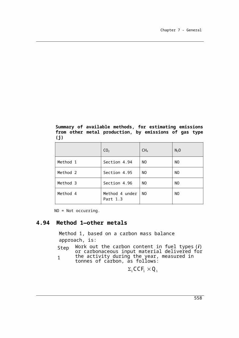
Appendices
Item Fuel type Carbon content factor
tC/t fuel
Fuels derived from recycled materials
8 Industrial materials and tyres that are derived from fossil fuels, if recycled and combusted to produce heat or electricity
0.585
9 Non-biomass municipal materials, if recycled and combusted to produce heat or electricity
0.250
Primary solid biomass fuels
10 Dry wood 0
11 Green and air dried wood 0
12 Sulphite lyes 0
13 Bagasse 0
14 Biomass municipal and industrial materials, if recycled and combusted to produce heat or electricity
0
15 Charcoal 0
16 Primary solid biomass fuels other than those mentioned in items 10 to 15
0
558

Appendices
Part 2 Gaseous fuels
Item Fuel type Carbon content factor
(tC/m3 of fuel unless otherwise specified)
Gaseous fossil fuels
17 Natural gas if distributed in a pipeline 5.52 × 10⁻⁴
17A Natural gas, if:(a) distributed in a pipeline; and(b) measured in units of gigajoules only
1.40 × 10⁻² tC/GJ of fuel
18 Coal seam methane that is captured for combustion 5.29 × 10⁻⁴
19 Coal mine waste gas that is captured for combustion 5.34 × 10⁻⁴
20 Compressed natural gas that has reverted to standard conditions
5.52 × 10⁻⁴
21 Unprocessed natural gas 5.52 × 10⁻⁴
22 Ethane 9.70 × 10⁻⁴
23 Coke oven gas 1.83 × 10⁻⁴
24 Blast furnace gas 2.55 × 10⁻⁴
25 Town gas 6.41 × 10⁻⁴
26 Liquefied natural gas 0.355 tC/kL of fuel
27 Gaseous fossil fuels other than those mentioned in items 17 to 26
5.52 × 10⁻⁴
Biogas captured for combustion
28 Landfill biogas (methane) that is captured for combustion 0
29 Sludge biogas (methane) that is captured for combustion 0
30 A biogas (methane) that is captured for combustion, other than those mentioned in items 28 and 29
0
Part 3 Liquid fuels and certain petroleum-based products
559

Appendices
Item Fuel type Carbon content factor
(tC/kL of fuelunless otherwise specified)
Petroleum based oils and petroleum based greases
31 Petroleum based oils (other than petroleum based oils used as fuel)
0.737
32 Petroleum based greases 0.737
Petroleum based products other than petroleum based oils and petroleum based greases
33 Crude oil including crude oil condensates 0.861 tC/t fuel
34 Other natural gas liquids 0.774 tC/t fuel
35 Gasoline (other than for use as fuel in an aircraft) 0.629
36 Gasoline for use as fuel in an aircraft 0.605
37 Kerosene (other than for use as fuel in an aircraft) 0.705
38 Kerosene for use as fuel in an aircraft 0.699
39 Heating oil 0.708
40 Diesel oil 0.736
41 Fuel oil 0.797
42 Liquefied aromatic hydrocarbons 0.654
43 Solvents if mineral turpentine or white spirits 0.654
44 Liquefied petroleum gas 0.422
45 Naphtha 0.597
46 Petroleum coke 0.856 tC/t fuel
47 Refinery gas and liquids 0.641 tC/t fuel
48 Refinery coke 0.856 tC/t fuel
49 Bitumen 0.951 tC/t fuel
50 Waxes 0.871 tC/t fuel
51 Petroleum based products other than:(a) petroleum based oils and petroleum based greases
mentioned in items 31 and 32; and(b) the petroleum based products mentioned in items 33
to 50
0.654
Biofuels
560
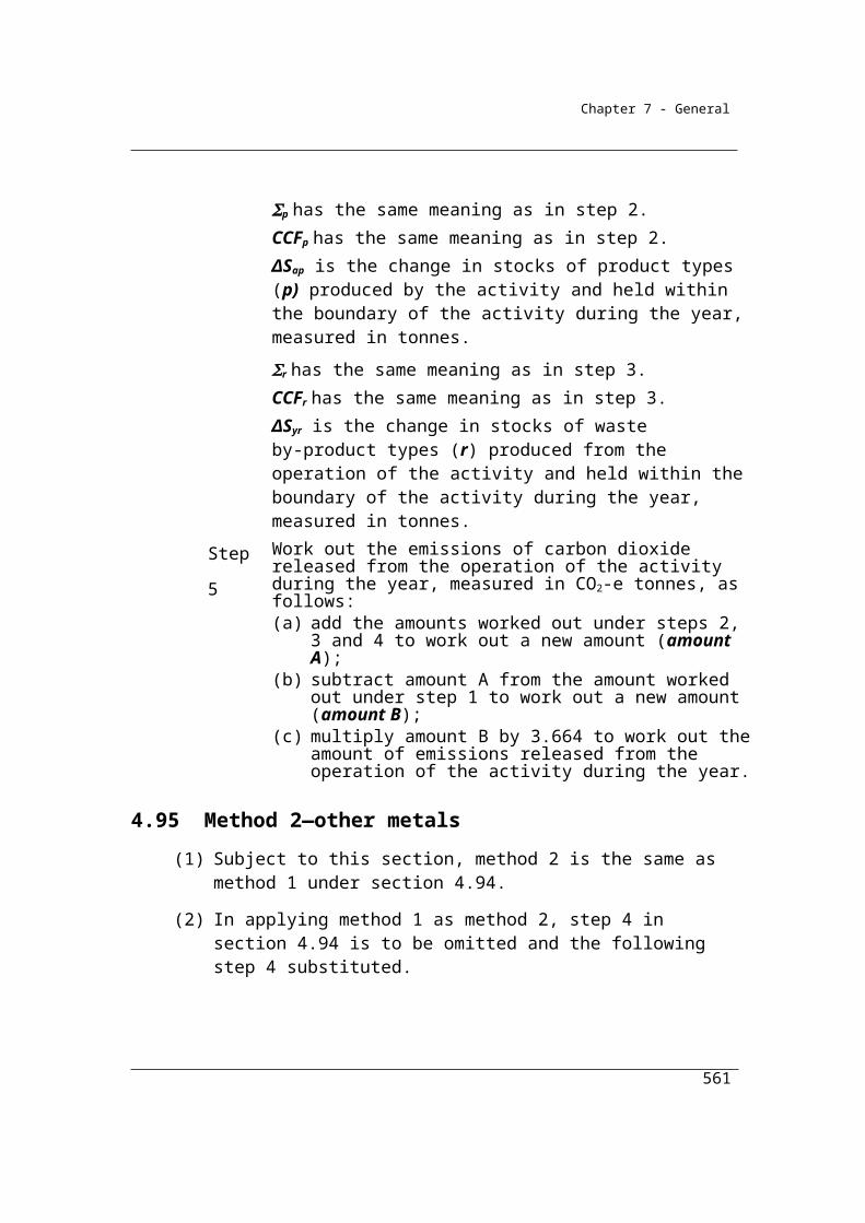
Appendices
Item Fuel type Carbon content factor
(tC/kL of fuelunless otherwise specified)
52 Biodiesel 0
53 Ethanol for use as a fuel in an internal combustion engine 0
54 Biofuels other than those mentioned in items 52 and 53 0
Part 4 Petrochemical feedstocks and products
Item Fuel type Carbon content factor
(tC/t fuelunless otherwise specified)
Petrochemical feedstocks
55 Carbon black if used as a petrochemical feedstock 1
56 Ethylene if used as a petrochemical feedstock 0.856
57 Petrochemical feedstock other than those mentioned in items 55 and 56
0.856
Petrochemical products
58 Propylene 0.856
59 Polyethylene 0.856
60 Polypropylene 0.856
61 Butadiene 0.888
62 Styrene 0.923
561

Appendices
Part 5 Carbonates
Item Carbonate type Carbon content factor (tC/t pure carbonate material unless otherwise specified)
63 Calcium carbonate 0.120
64 Magnesium carbonate 0.142
65 Sodium carbonate 0.113
66 Sodium bicarbonate 0.143
Notes on Carbon Content Factors
1. Energy value: Source – ABARE1 (washed steaming). CO2 emission factor: Source - National
Inventory Report 2006, Department of Climate Change.
1A. Energy value: Source – ABARE1 (washed steaming). CO2 emission factor: Source - National
Inventory Report 2006, Department of Climate Change.
1B. Energy value: Source – ABARE1 (washed steaming). CO2 emission factor: Source - National
Inventory Report 2006, Department of Climate Change.
2. Energy value: Source - AGEIS database, Department of Climate Change and Energy
Efficiency (based on facility reports). CO2 emission factor: Source - AGEIS database, Department of
Climate Change and Energy Efficiency (based on facility reports).
3. Energy value: Source – ABARE1 (washed coking). CO2 emission factor: Source - National
Inventory Report 2006, Department of Climate Change.
4. Energy value: Source – ABARE1. CO2 emission factor: Source - AGEIS database,
Department of Climate Change and Energy Efficiency (based on facility reports).
562

Appendices
5. Energy value: Source – ABARE1. CO2 emission factor: Source – National Inventory Report
2006, Department of Climate Change.
6. Energy value: Source – ABARE1. CO2 emission factor: Source – National Inventory Report
2006, Department of Climate Change (coal tar).
7. See (4)
8. Energy value: Source – GHD Review of Sectoral Models, Internal report to the AGO, 2006.
CO2 emission factor: Source – National Inventory Report 2006, Department of Climate Change.
9. Energy value: Source – IPCC 2006. Derived from NCV using factor of 5% of gross calorific
value. CO2 emission factor: Source: IPCC 2006. Derived using conversion factor of 0.95.
10. Energy value: Source: ABARE1 (dry wood).
11. Energy value: Source: ABARE1 (green wood).
12. Energy value: Source – IPCC 2006. Derived from NCV using factor of 5% of gross calorific
value. .
13. Energy value: Source: ABARE1.
14. Energy value: Source – IPCC 2006. Derived from NCV using factor of 5% of gross calorific
value.
563
Appendices
15. Energy value: Source – IPCC 2006. Derived from NCV using factor of 5% of gross calorific
value.
16. See (14)
17. Energy value: Source: ABARE1 (weighted average). CO2 emission factor: Source - AGEIS
database, Department of Climate Change and Energy Efficiency.
17A Energy value: Source: ABARE1 (weighted average). CO2 emission factor: Source - AGEIS
database, Department of Climate Change and Energy Efficiency.
18. Energy value: Source: ABARE1 (coal seam methane). CO2 emission factor: Source - AGEIS
database, Department of Climate Change and Energy Efficiency.
19. Energy value: Source: ABARE1 (coal seam methane). CO2 emission factor: Source - AGEIS
database, Department of Climate Change and Energy Efficiency.
20. See (17)
21. See (17)
22. Energy value: Source: ABARE1 (average). CO2 emission factor: Source – National Inventory
Report 2008, Department of Climate Change and Energy Efficiency (forthcoming).
23. Energy value: Source: ABARE1. CO2 emission factor: Source – National Inventory Report
2006, Department of Climate Change.
564
Appendices
24. Energy value: Source – ABARE1. CO2 emission factor: Source: IPCC 2006. Derived using
conversion factor of 0.90.
25. Energy value: Source – ABARE2 (synthetic natural gas). CO2 emission factor: Source:
National Inventory Report 2006, Department of Climate Change.
26. Energy value: Source – ABARE1. CO2 emission factor: Source - AGEIS database,
Department of Climate Change and Energy Efficiency.
27. See (17)
28. Energy value: Source – ABARE1.
29. Energy value: Source – ABARE1.
30. See (28)
31. Energy value: Source – ABARE2 (lubricants and greases). CO2 emission factor:
Source: National Inventory Report 2006, Department of Climate Change (lubricants and greases).
32. Energy value: Source – ABARE2 (lubricants and greases). CO2 emission factor:
Source: National Inventory Report 2006, Department of Climate Change (lubricants and greases).
565

Appendices
33. Energy value: Source – ABARE2 (weighted average). CO2 emission factor: Source: IPCC
2006. Derived using conversion factor of 0.95.
34. Energy value: Source – IPCC 2006. Derived from NCV using factor of 5% of gross calorific
value. CO2 emission factor: Source: IPCC 2006. Derived using conversion factor of 0.95.
35. Energy value: Source – ABARE2. CO2 emission factor: Source: National Inventory Report
2006, Department of Climate Change.
36. Energy value: Source – ABARE2. CO2 emission factor: Source: National Inventory Report
2006, Department of Climate Change.
37. Energy value: Source – ABARE2 (power kerosene). CO2 emission factor: Source:
National Inventory Report 2006, Department of Climate Change.
38. Energy value: Source – ABARE2. CO2 emission factor: Source: National Inventory Report
2006, Department of Climate Change.
39. Energy value: Source – ABARE2. CO2 emission factor: Source: National Inventory Report
2006, Department of Climate Change.
40. Energy value: Source – ABARE2. CO2 emission factor: Source: National Inventory Report
2006, Department of Climate Change.
41. Energy value: Source – ABARE2 (low sulphur). CO2 emission factor: Source: National
Inventory Report 2006, Department of Climate Change. Derived using conversion factor of 0.95.
566
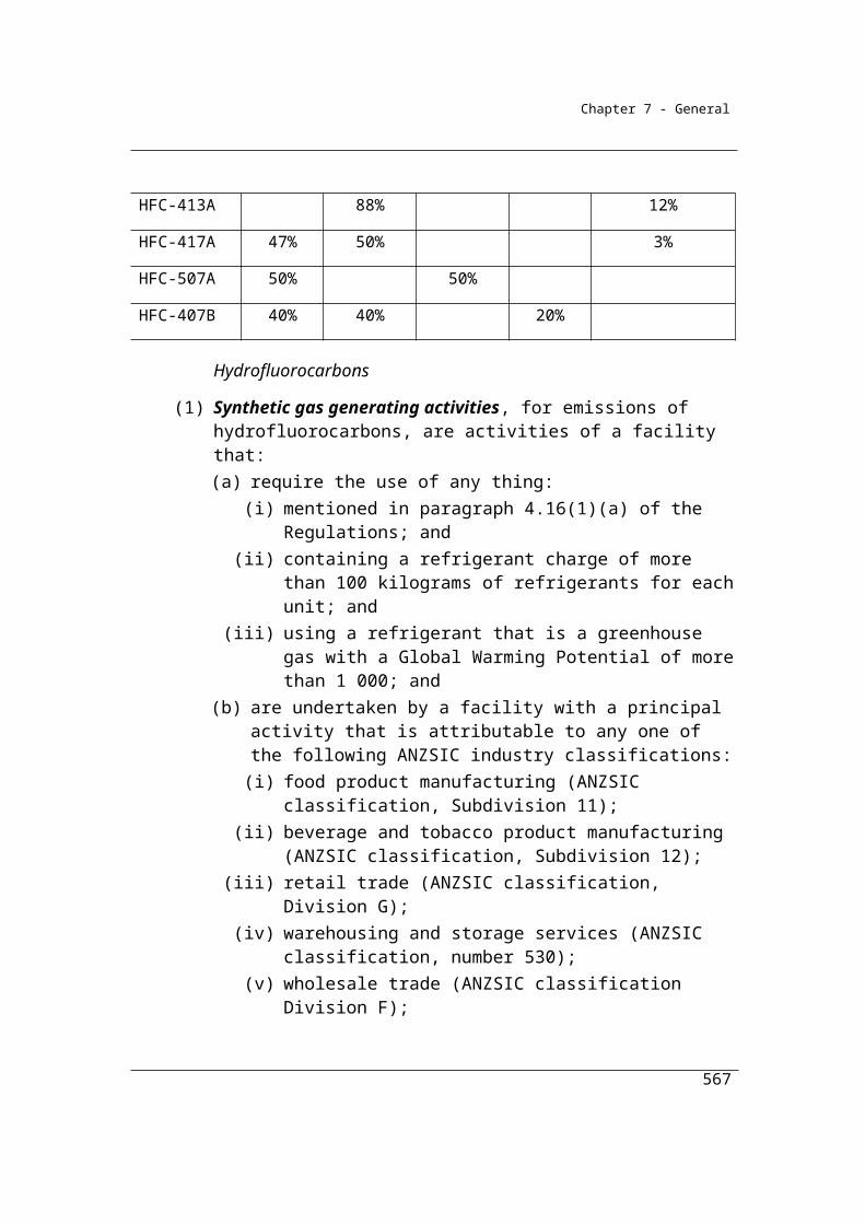
Appendices
42. Energy value: Source – ABARE2. Given same energy content as solvents. CO2 emission
factor: Source: National Inventory Report 2006, Department of Climate Change (assumed same as
solvents).
43. Energy value: Source – ABARE2. CO2 emission factor: National Inventory Report 2006,
Department of Climate Change.
44. Energy value: Source – ABARE2. CO2 emission factor: Source: National Inventory Report
2006, Department of Climate Change. .
45. Energy value: Source – ABARE2. CO2 emission factor: Source: National Inventory Report
2006, Department of Climate Change.
46. Energy value: Source – IPCC 2006. CO2 emission factor: Source: IPCC 2006. Derived using
conversion factor of 0.95.
47. Energy value: Source – ABARE1 (refinery fuel). CO2 emission factor: Source: IPCC 2006.
Derived using conversion factor of 0.95.
48. See (46)
49. Energy value: Source – ABARE1. CO2 emission factor: Source: National Inventory Report
2006, Department of Climate Change.
50. Energy value: Source – ABARE2. CO2 emission factor: Source: National Inventory Report
2006, Department of Climate Change (assumed same as solvents).
567
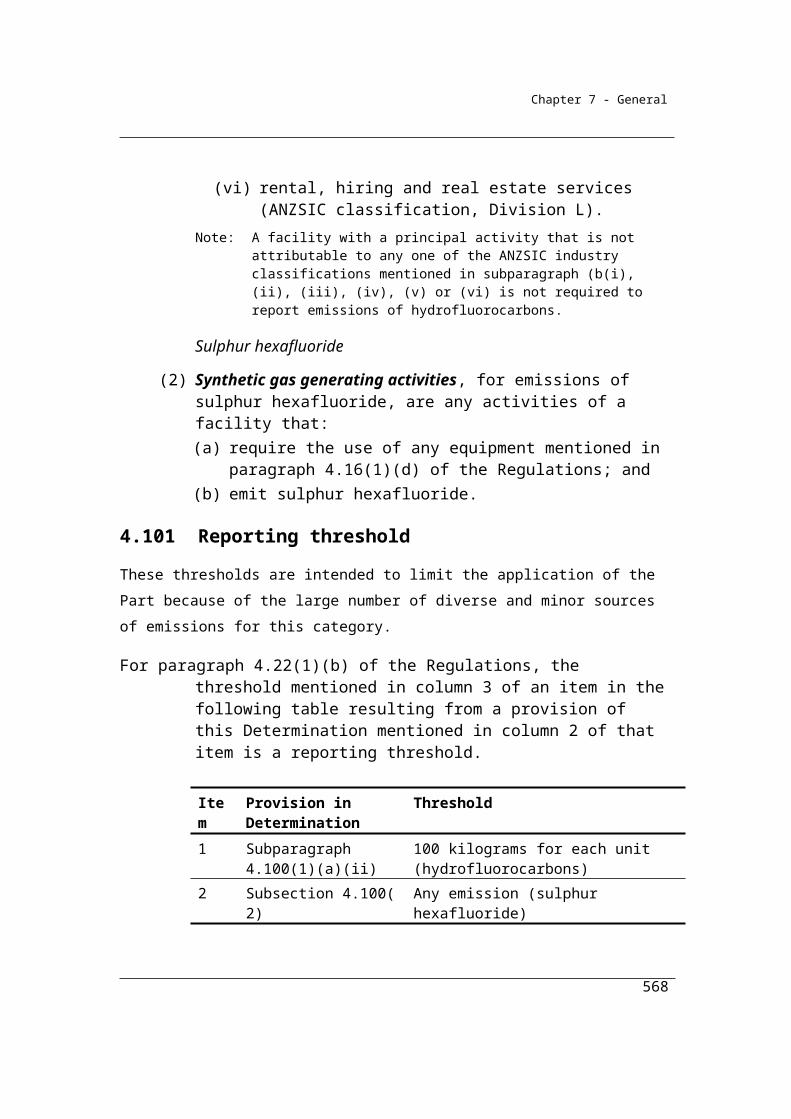
Appendices
51. Energy value: Source – ABARE2. Based on IPCC 2006, given same energy content as
solvents. CO2 emission factor: Source: National Inventory Report 2006, Department of Climate
Change (set same as solvents).
52. Energy value: Source – Derived from US Department of Energy. Non-CO2 factors: IPCC
2006. Derived using conversion factor 0.95.
53. Energy value: Source – ABARE2. Non-CO2 factors: IPCC 2006. Derived using conversion
factor 0.95.
54. See (53).
55. Assumed to be 100% carbon
56. Carbon content obtained through stoichiometric estimation
57. Carbon content assumed the same as ethylene
58. Carbon content obtained through stoichiometric estimation
59. Carbon content obtained through stoichiometric estimation
60. Carbon content obtained through stoichiometric estimation
61. Carbon content obtained through stoichiometric estimation
568

Appendices
62. Carbon content obtained through stoichiometric estimation
63. Carbon content obtained through stoichiometric estimation
64. Carbon content obtained through stoichiometric estimation
65. Carbon content obtained through stoichiometric estimation
66. Carbon content obtained through stoichiometric estimation
Notes:
ABARE1 2007 Fuel and Electricity Survey – Fuel Codes, Australian Bureau of Agricultural and
Resource Economics www.abareconomics.com/publications_html/surveys/surveys/surveys.html,
Commonwealth of Australia, Canberra.
ABARE2 2007 Energy in Australia 2006, produced for Department of Industry, Tourism and
Resources, pages 77-79, Commonwealth of Australia, Canberra.
Department of Climate Change and Energy Efficiency (2008), National Inventory Report 2006,
Commonwealth of Australia, Canberra
Intergovernmental Report on Climate Change (2006), 2006 IPCC Guidelines for National Greenhouse
Gas Inventories; Japan.
569
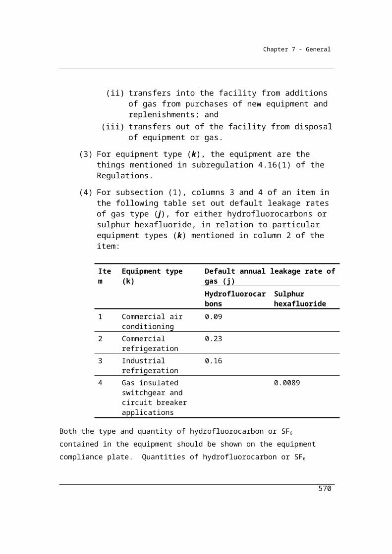
Appendices
Appendix B: Definitions and interpretation
Definitions
2006 IPCC Guidelines means the 2006 IPCC Guidelines for National Greenhouse Gas Inventories published by the IPCC.
ACARP Guidelines means the document entitled Guidelines for the Implementation of NGER Method 2 or 3 for Open Cut Coal Mine Fugitive GHG Emissions Reporting (C20005), published by the Australian Coal Association Research Program in December 2011.
accredited laboratory means a laboratory accredited by the National Association of Testing Authorities or an equivalent member of the International Laboratory Accreditation Cooperation in accordance with AS ISO/IEC 17025:2005, and for the production of calibration gases, accredited to ISO Guide 34:2000.
Act means the National Greenhouse and Energy Reporting Act 2007.
active gas collection means a system of wells and pipes that collect landfill gas through the use of vacuums or pumps.
alternative waste treatment activity means an activity that:(a) accepts and processes mixed waste using:
(i) mechanical processing; and(ii) biological or thermal processing; and
(b) extracts recyclable materials from the mixed waste.
alternative waste treatment residue means the material that remains after waste has been processed and organic rich material has been removed by physical screening or sorting by an alternative waste treatment activity that produces compost, soil conditioners or mulch in accordance with:
(a) State or Territory legislation; or(b) Australian Standard AS 4454:2012.
ANZSIC industry classification and code means an industry classification and code for that classification published in the Australian and New Zealand Standard Industrial Classification (ANZSIC), 2006.
APHA followed by a number means a method of that number issued by the American Public Health Association and, if a date is included, of that date.
570
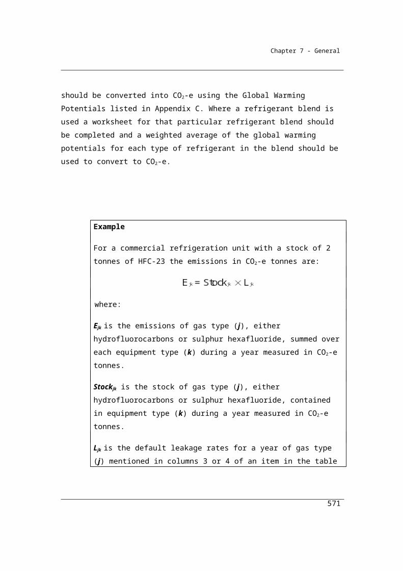
Appendices
API Compendium means the document entitled Compendium of Greenhouse Gas Emissions Methodologies for the Oil and Natural Gas Industry, published in August 2009 by the American Petroleum Institute.Note: The API Compendium is available at www.api.org.
applicable State or Territory legislation, for an underground mine, means a law of a State or Territory in which the mine is located that relates to coal mining health and safety, including such a law that prescribes performance-based objectives, as in force on 1 July 2008.Note: Applicable State or Territory legislation includes:
Coal Mine Health and Safety Act 2002 (NSW) and the Coal Mine Health and Safety Regulation 2006 (NSW)
Coal Mining Safety and Health Act 1999 (Qld) and the Coal Mining Safety and Health Regulation 2001 (Qld).
appropriate standard, for a matter or circumstance, means an Australian standard or an equivalent international standard that is appropriate for the matter or circumstance.
appropriate unit of measurement, in relation to a fuel type, means:(a) for solid fuels—tonnes; and(b) for gaseous fuels—metres cubed or gigajoules, except for liquefied natural
gas which is kilolitres; and(c) for liquid fuels other than those mentioned in paragraph (d)—kilolitres; and(d) for liquid fuels of one of the following kinds—tonnes:
(i) crude oil, including crude oil condensates, other natural gas liquids;(ii) petroleum coke;
(iii) refinery gas and liquids;(iv) refinery coke;(v) bitumen:
(vi) waxes;(vii) carbon black if used as petrochemical feedstock;
(viii) ethylene if used as a petrochemical feedstock;(ix) petrochemical feedstock mentioned in item 57 of Schedule 1 to the
Regulations.
AS or Australian standard followed by a number (for example, AS 4323.1—1995) means a standard of that number issued by Standards Australia Limited and, if a date is included, of that date.
ASTM followed by a number (for example, ASTM D6347/D6347M-99) means a standard of that number issued by ASTM International and, if a date is included, of that date.
571

Appendices
Australian legal unit of measurement has the meaning given by the National Measurement Act 1960.
base of the low gas zone means the part of the low gas zone worked out in accordance with section 3.25A.
basin means a geological basin named in the Australian Geological Provinces Database.Note: The Australian Geological Provinces Database is available at www.ga.gov.au.
biogenic carbon fuel means energy that is:(a) derived from plant and animal material, such as wood from forests,
residues from agriculture and forestry processes and industrial, human or animal wastes; and
(b) not embedded in the earth for example, like coal oil or natural gas.
blended fuel means fuel that is a blend of fossil and biogenic carbon fuels.
briquette means an agglomerate formed by compacting a particulate material in a briquette press, with or without added binder material.
calibrated to a measurement requirement, for measuring equipment, means calibrated to a specific characteristic, for example a unit of weight, with the characteristic being traceable to:
(a) a measurement requirement provided for under the National Measurement Act 1960 or any instrument under that Act for that equipment; or
(b) a measurement requirement under an equivalent standard for that characteristic.
captured for permanent storage, in relation to carbon dioxide, has the meaning given by section 1.19A.
carbon dioxide stream means a stream of gaseous substances that consists overwhelmingly of carbon dioxide that is captured for permanent storage.
CEM or continuous emissions monitoring means continuous monitoring of emissions in accordance with Part 1.3.
CEN/TS followed by a number (for example, CEN/TS 15403) means a technical specification (TS) of that number issued by the European Committee for Standardization and, if a date is included, of that date.
CO2-e means carbon dioxide equivalence.
coal seam methane has the same meaning as in the Regulations.
572
Appendices
COD or chemical oxygen demand means the total material available for chemical oxidation (both biodegradable and non-biodegradable) measured in tonnes.
compressed natural gas has the meaning given by the Regulations.
core sample means a cylindrical sample of the whole or part of a strata layer, or series of strata layers, obtained from drilling using a coring barrel with a diameter of between 50 mm and 2 000 mm.
crude oil condensates has the meaning given by the Regulations.
crude oil transport means the transportation of marketable crude oil to heavy oil upgraders and refineries by means that include the following:
(a) pipelines;(b) marine tankers; (c) tank trucks; (d) rail cars.
designated fuel has the same meaning as in the Clean Energy Act 2011.
documentary standard means a published standard that sets out specifications and procedures designed to ensure that a material or other thing is fit for purpose and consistently performs in the way it was intended by the manufacturer of the material or thing.
domain, of an open cut mine, means an area, volume or coal seam in which the variability of gas content and the variability of gas composition in the open cut mine have a consistent relationship with other geological, geophysical or spatial parameters located in the area, volume or coal seam.
dry wood has the meaning given by the Regulations.
efficiency method has the meaning given by subsection 2.70(2).
EN followed by a number (for example, EN 15403) means a standard of that number issued by the European Committee for Standardization and, if a date is included, of that date.
enclosed composting activity means a semi-enclosed or enclosed alternative waste or composting technology where the composting process occurs within a reactor that:
(a) has hard walls or doors on all 4 sides; and(b) sits on a floor; and(c) has a permanent positive or negative aeration system.
573

Appendices
energy content factor, for a fuel, means gigajoules of energy per unit of the fuel measured as gross calorific value.
estimator, of fugitive emissions from an open cut mine using method 2 under section 3.21 or method 3 under section 3.26, means:
(a) an individual who has the minimum qualifications of an estimator set out in the ACARP Guidelines; or
(b) individuals who jointly have those minimum qualifications.
extraction area, in relation to an open cut mine, is the area of the mine from which coal is extracted.
feedstock has the meaning given by the Regulations.
ferroalloy has the meaning given by subsection 4.69(2).
flaring means the combustion of fuel for a purpose other than producing energy.Example: The combustion of methane for the purpose of complying with health, safety and
environmental requirements.
fuel means a substance mentioned in column 2 of an item in Schedule 1 to the Regulations other than a substance mentioned in items 58 to 66.
fuel oil has the meaning given by the Regulations.
fugitive emissions has the meaning given by the Clean Energy Regulations 2011.
gas bearing strata is coal and carbonaceous rock strata:(a) located in an open cut mine; and(b) that has a relative density of less than 1.95 g/cm3.
gaseous designated fuel means liquefied natural gas.
gaseous fuel means a fuel mentioned in column 2 of items 17 to 30 of Schedule 1 to the Regulations.
gas stream means the flow of gas subject to monitoring under Part 1.3.
gassy mine means an underground mine that has at least 0.1% methane in the mine’s return ventilation.
Global Warming Potential means, in relation to a greenhouse gas mentioned in column 2 of an item in the table in regulation 2.02 of the Regulations, the value mentioned in column 4 for that item.
GPA followed by a number means a standard of that number issued by the Gas Processors Association and, if a date is included, of that date.
574

Appendices
green and air dried wood has the meaning given by the Regulations.
GST group has the same meaning as in the Fuel Tax Act 2006.
GST joint venture has the same meaning as in the Fuel Tax Act 2006.
higher method has the meaning given by subsection 1.18(5).
hydrofluorocarbons has the meaning given by section 4.99.
ideal gas law means the state of a hypothetical ideal gas in which the amount of gas is determined by its pressure, volume and temperature.
IEC followed by a number (for example, IEC 17025:2005) means a standard of that number issued by the International Electrotechnical Commission and, if a date is included, of that date.
incidental, for an emission, has the meaning given by subregulation 4.27(5) of the Regulations.
independent expert, in relation to an operator of a landfill, means a person who:(a) is independent of the operator of the landfill; and(b) has relevant expertise in estimating or monitoring landfill surface gas.
inert waste means waste materials that contain no more than a negligible volume of degradable organic carbon and includes the following waste:
(a) concrete;(b) metal;(c) plastic;(d) glass;(e) asbestos concrete;(f) soil.
integrated metalworks has the meaning given by subsection 4.64(2).
invoice includes delivery record.
invoice equivalent means a document (including an electronic document) or series of documents that are intended to be used as evidence of natural gas supply (for example, for commercial or taxation purposes) and from which the following information can be ascertained:
(a) the identity of the natural gas supplier;(b) the identity of the recipient of natural gas;(c) the amount of natural gas supplied;(d) the period to which the supply relates;(e) the date the document was issued.
575
Appendices
Example: Where natural gas is supplied directly from a natural gas transmission pipeline, volume reports provided by the pipeline operator or wholesale supplier will be invoice equivalents.
IPCC is short for Intergovernmental Panel on Climate Change established by the World Meteorological Organization and the United Nations Environment Programme.
ISO followed by a number (for example, ISO 10396:2007) means a standard of that number issued by the International Organization of Standardization and, if a date is included, of that date.
legacy waste means waste deposited at a landfill before 1 July 2012.
liquefied natural gas has the same meaning as in the Regulations.
liquefied petroleum gas has the same meaning as in the Regulations.
liquid designated fuel means:(a) liquefied petroleum gas; and(b) specified taxable fuel.
liquid fuel means a fuel mentioned in column 2 of items 31 to 54 of Schedule 1 to the Regulations.
lower method has the meaning given by subsection 1.18(6).
low gas zone means the part of the gas bearing strata of an open cut mine:(a) that is located immediately below the original surface of the mine and
above the base of the low gas zone; and(b) the area of which is worked out by working out the base of the low gas
zone.
main electricity grid has the meaning given by subsection 7.2(4).
marketable crude oil includes:(a) conventional crude oil; and(b) heavy crude oil; and(c) synthetic crude oil; and(d) bitumen.
method means a method specified in this determination for estimating:(a) emissions released from the operation of a facility in relation to a source; or(b) the potential emissions embodied in an amount of designated fuel.
municipal materials has the meaning given by the Regulations.
576
Appendices
municipal solid waste class I means waste from domestic premises, council collections and other municipal sources where:
(a) the collection of organic waste on a regular basis in a dedicated bin is not provided to residents of the municipality as a standard practice; or
(b) the collection of organic waste on a regular basis in a dedicated bin provided to residents of the municipality cannot be confirmed as standard practice.
municipal solid waste class II means waste from domestic premises, council collections and other municipal sources where a bin dedicated for garden waste is:
(a) provided to residents of the municipality as a standard practice; and(b) collected on a regular basis.
N/A means not available.
National Greenhouse Accounts means the set of national greenhouse gas inventories, including the National Inventory Report 2005, submitted by the Australian government to meet its reporting commitments under the United Nations Framework Convention on Climate Change and the 1997 Kyoto Protocol to that Convention.
natural gas has the meaning given by the Regulations.
natural gas distribution is distribution of natural gas through low-pressure pipelines with pressure of 1 050 kilopascals or less.
natural gas liquids has the meaning given by the Regulations.
natural gas supply pipeline has the meaning given by the Clean Energy Act 2011.
natural gas transmission is transmission of natural gas through high-pressure pipelines with pressure greater than 1 050 kilopascals.
netted out number has:(a) in relation to liquefied petroleum gas and liquefied natural gas imported
into Australia, the same meaning as in section 36B of the Clean Energy Act 2011 and any regulations made under that section; and
(b) in relation to liquefied petroleum gas and liquefied natural gas manufactured or produced in Australia, the same meaning as in section 36C of the Clean Energy Act 2011 and any regulations made under that section; and
(c) in relation to liquefied petroleum gas and liquefied natural gas supplied to a person who quotes an OTN, the same meaning as in section 36D of the Clean Energy Act 2011 and any regulations made under that section.
577

Appendices
non-gassy mine means an underground mine that has less than 0.1% methane in the mine’s return ventilation.
non-legacy waste means waste deposited at a landfill on or after 1 July 2012.
open cut mine:(a) means a mine in which the overburden is removed from coal seams to
allow coal extraction by mining that is not underground mining; and(b) for method 2 in section 3.21 or method 3 in section 3.26—includes a mine
of the kind mentioned in paragraph (a):(i) for which an area has been established but coal production has not
commenced; or(ii) in which coal production has commenced.
Opt-in Scheme has the same meaning as in the Clean Energy Act 2011.
OTN has the same meaning as in the Clean Energy Act 2011.
PEM or periodic emissions monitoring means periodic monitoring of emissions in accordance with Part 1.3.
Perfluorocarbon protocol means the Protocol for Measurement of Tetrafluoromethane (CF4) and Hexafluoroethane (C2F6) Emissions from Primary Aluminium Production published by the United States Environmental Protection Agency and the International Aluminium Institute.
petroleum based greases has the meaning given by regulation 1.03 of the Regulations.
petroleum based oils has the meaning given by the Regulations.
petroleum coke has the meaning given by the Regulations.
phytocap means an evapotranspiration landfill capping system that makes use of soil and vegetation to store and release surface water.
point of liability means:(a) for liquefied natural gas (LNG) or liquefied petroleum gas (LPG) that was
produced in or imported into Australia—the point at which the LNG or LPG is entered for home consumption; or
(b) for LNG or LPG that was supplied in association with an OTN quotation or misuse of an OTN quotation—the point at which the LNG or LPG is supplied; or
(c) for LNG or LPG that is attributable to a netted out number, but not an OTN quotation—the point at which the LNG or LPG is used; or
578
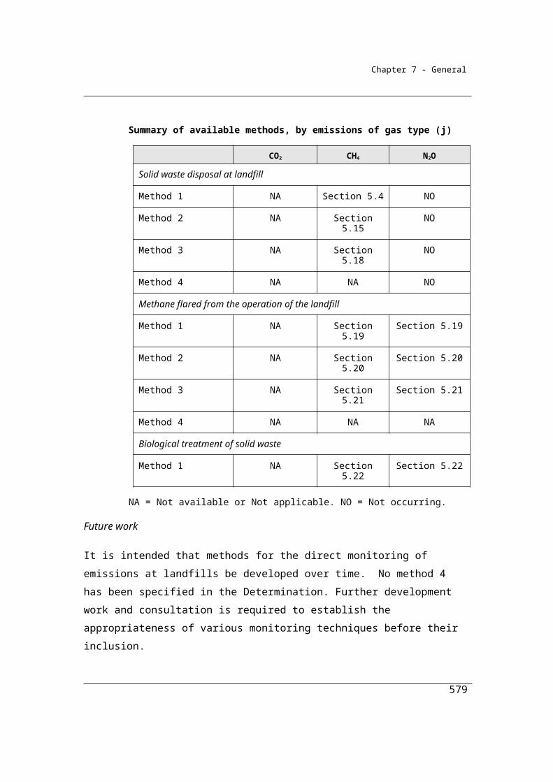
Appendices
(d) for acquisition, importation or manufacture of specified taxable fuel by a participant in the Opt-in Scheme:
(i) for fuel that is used by the participant that has been entered for home consumption—the point at which the fuel is entered for home consumption; or
(ii) if subparagraph (i) does not apply—the point at which the fuel is acquired.
post-mining activities, in relation to a mine, is the handling, stockpiling, processing and transportation of coal extracted from the mine.
primary wastewater treatment plant:(a) means a treatment facility at which wastewater undergoes physical
screening, degritting and sedimentation; and(b) does not include a treatment facility at which any kind of nitrification or
denitrification treatment process occurs.
principal activity, in relation to a facility, means the activity that:(a) results in the production of a product or service that is produced for sale on
the market; and(b) produces the most value for the facility out of any of the activities forming
part of the facility.
pyrolysis of coal means the decomposition of coal by heat.
raw sugar has the meaning given by Chapter 17 of Section IV of Schedule 3 to the Customs Tariff Act 1995.
reductant:(a) means a reducing agent or substance:
(i) that causes another substance to undergo reduction; and(ii) that is oxidised while causing the substance to undergo reduction; and
(b) does not include fuels that are combusted only to produce energy.
refinery gases and liquids has the meaning given by the Regulations.
Regulations means the National Greenhouse and Energy Reporting Regulations 2008.
relevant person means a person mentioned in paragraph 1.19A(a), (b), (c), (d), (e) or (f).
run-of-mine coal means coal that is produced by mining operations before screening, crushing or preparation of the coal has occurred.
scope 1 emissions has the same meaning as in the Regulations.
579

Appendices
scope 2 emissions has the same meaning as in the Regulations.
separate instance of a source has the meaning given by section 1.9A.
separate occurrence of a source has the meaning given by section 1.9B.
shale gas means a substance that:(a) consists of:
(i) naturally occurring hydrocarbons; or(ii) a naturally occurring mixture of hydrocarbons and non-hydrocarbons;
and(b) consists mainly of methane; and(c) is drained from shale formations.
shredder flock means the residual waste generated from the process of scrap metal processing that ends up in landfill.
sludge biogas has the meaning given by the Regulations.
sludge lagoon means a component of a wastewater treatment system that:(a) is used to stabilise and dry excess or wasted sludge from the liquid or solid
phase treatment train of a wastewater treatment plant; and(b) involves biodegradation of COD in the form of sludge and the use of
ambient climatic factors to reduce the moisture content of the sludge.
solid fuel means a fuel mentioned in column 2 of items 1 to 16 of Schedule 1 to the Regulations.
source has the meaning given by section 1.10.
specified taxable fuel has the meaning given by regulation 3.30 of the Clean Energy Regulations 2011.
standard includes a protocol, technical specification or USEPA method.
standard conditions has the meaning given by subsection 2.32(7).
sulphite lyes has the meaning given by the Regulations.
supply has the meaning given by the Clean Energy Act 2011.
synthetic gas generating activities has the meaning given by subsections 4.100(1) and (2).
technical guidelines means the document published by the Department and known as the National Greenhouse Energy and Reporting (Measurement) Technical Guidelines 2009.
580
Appendices
tight gas means a substance that:(a) consists of:
(i) naturally occurring hydrocarbons; or(ii) a naturally occurring mixture of hydrocarbons and non-hydrocarbons;
and(b) consists mainly of methane; and(c) is drained from low permeability sandstone and limestone reservoirs.
uncertainty protocol means the publication known as the GHG protocol guidance on uncertainty assessment in GHG inventories and calculating statistical parameter uncertainty (September 2003) v1.0 issued by the World Resources Institute and the World Business Council for Sustainable Development.
underground mine means a coal mine that allows extraction of coal by mining at depth, after entry by shaft, adit or drift, without the removal of overburden.
USEPA followed by a reference to a method (for example, Method 3C) means a standard of that description issued by the United States Environmental Protection Agency.
waxes has the meaning given by the Regulations.
well completion means the period that:(a) begins on the initial gas flow in the well; and(b) ends on whichever of the following occurs first:
(i) well shut in; or(ii) continuous gas flow from the well to a flow line or a storage vessel
for collection.
well workover means the period that:(a) begins on the initial gas flow in the well that follows remedial operations to
increase the well’s production; and(b) ends on whichever of the following occurs first:
(i) well shut in; or(ii) continuous gas flow from the well to a flow line or a storage vessel
for collection.
year means a financial year.Note: The following expressions in this Determination are defined in the Act:
carbon dioxide equivalence consumption of energy (see also regulation 2.26 of the Regulations) energy facility greenhouse gas
581
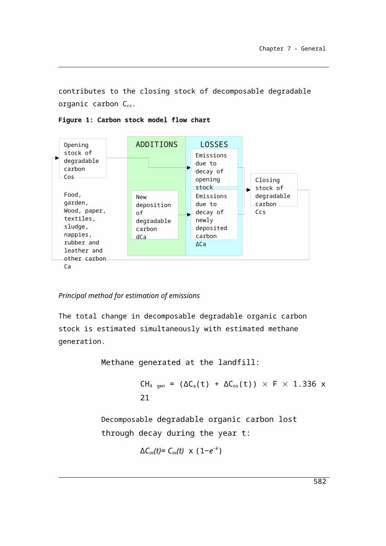
Appendices
group industry sector operational control potential greenhouse gas emissions production of energy (see also regulation 2.25 of the Regulations) registered corporation scope 1 emission (see also regulation 2.23 of the Regulations) scope 2 emission (see also regulation 2.24 of the Regulations).
582
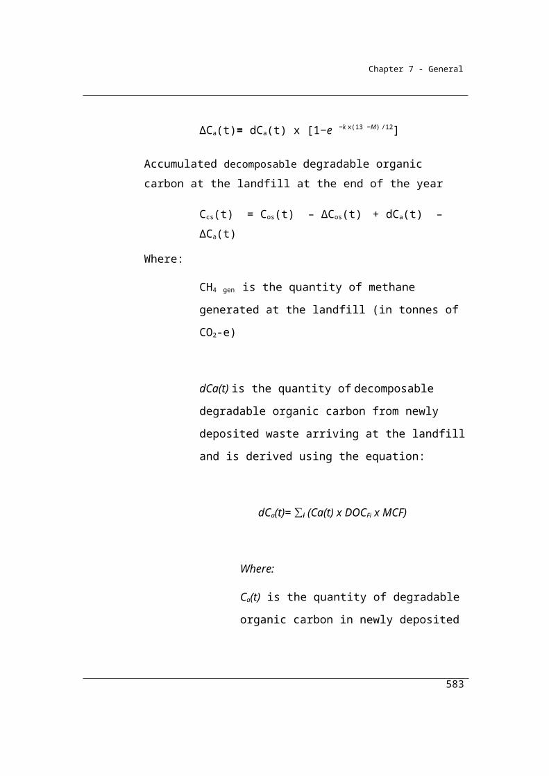
Appendices
Interpretation
Ethanol is the part of the fuel that relates to the quantities of biofuel and not to the total volume of liquids into which the biofuels are blended. Emission and energy content factors for ethanol apply to pure ethanol and not ‘denatured’ ethanol.
Liquefied petroleum gas are derived from refinery processes, crude oil stabilisation plants and natural gas processing plants, comprising propane, butane or a combination of the two. They are normally liquefied under pressure for transportation and storage.
Coal seam methane that is captured for combustion can be applied to a pipeline containing natural gas. If consumers are unable to determine whether the natural gas distributed in a pipeline is natural gas or coal seam methane then it is reasonable to report the fuel consumption as natural gas distributed in a pipeline.
583
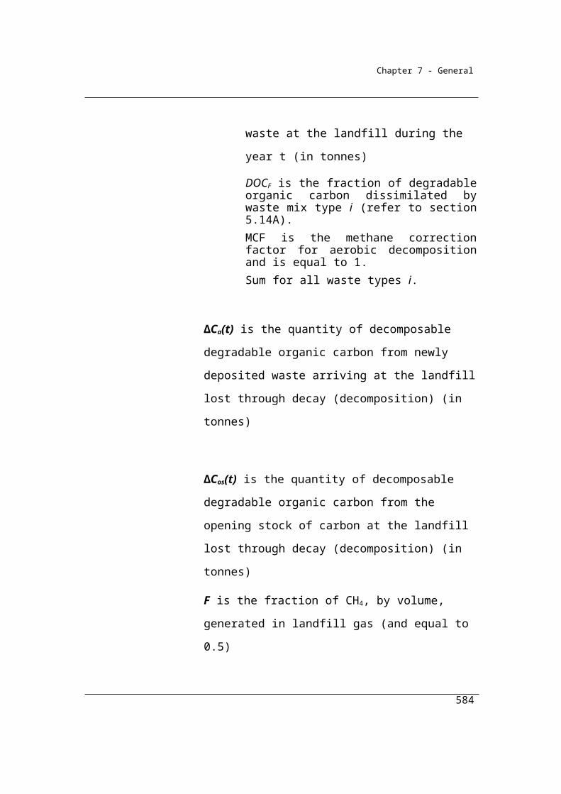
Appendices
Appendix C: Global Warming Potentials, Units and Conversions
Global Warming Potentials
Greenhouse Gas Chemical Formula Global Warming
Potential (GWP)
Carbon dioxide CO2 1
Methane CH4 25
Nitrous oxide N2O 298
Sulphur hexafluoride SF6 22 800
HFC-23 CHF3 14 800
HFC-32 CH2F2 675
HFC-41 CH3F2 92
HFC-43-10mee C5H2F10 1 640
HFC-125 C2HF5 3 500
HFC-134 C2H2F4 (CHF2CHF2) 1 100
HFC-134a C2H2F4 (CH2FCF3) 1 430
HFC-143 C2H3F3 (CHF2CH2F) 353
HFC-143a C2H3F3 (CF3CH3) 4 470
HFC-152a C2H4F2 (CH3CHF2) 124
HFC-227ea C3HF7 3 220
HFC-236fa C3H2F6 9 810
HFC-245ca C3H3F5 693
Perfluoromethane (tetrafluoromethane) CF4 7 390
Perfluoroethane (hexafluoroethane) C2F6 12 200
Perfluoropropane C3F8 8 830
Perfluorobutane C4F10 8 860
Perfluorocyclobutane c-C4F8 10 300
Perfluoropentane C5F12 9 160
Perfluorohexane C6F14 9 300
584

Appendices
Note 1: Global Warming Potential (also known as GWP) is defined in the Glossary published by the UNFCCC
as an index representing the combined effect of the differing times greenhouse gases remain in the atmosphere and
their relative effectiveness in absorbing outgoing infrared radiation.
Note 2: The Global Warming Potential figures in the above table are the figures published by the
Intergovernmental Panel on Climate Change in Climate Change 2007: The Physical Science Basis (Cambridge, UK:
Cambridge University Press, 2007).
585
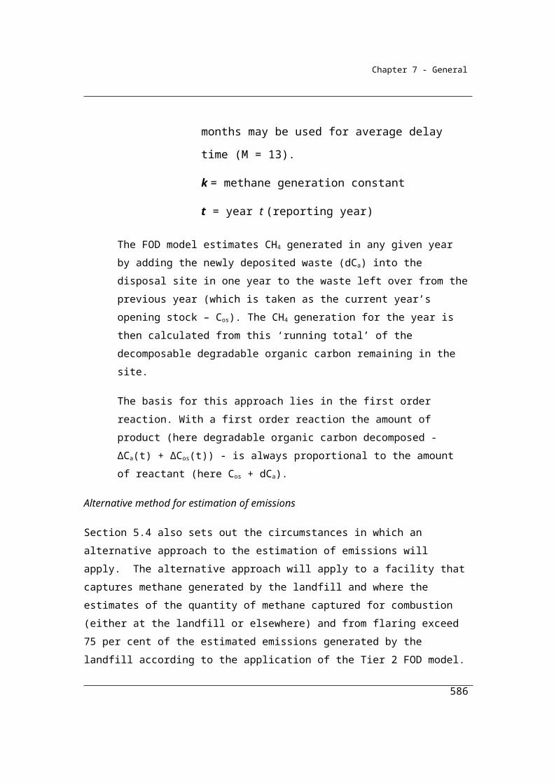
Appendices
Metric prefixes
Prefix Abbreviation Symbol
Peta (million billion [thousand trillion]) 1015 (106x109) P
Tera (thousand billion [trillion]) 1012 (103x109) T
Giga (billion) 109 G
Mega (million) 106 M
kilo (thousand) 103 k
hecto 102 h
deca 101 da
– (e.g. gram) 100 g
deci 10-1 d
centi 10-2 c
milli 10-3 m
micro 10-6 µ
nano 10-9 n
pico 10-12 p
Unit equivalences
1015 grams (Petagram) Gigatonne (Gt)
1012 grams (Teragram) Megatonne (Mt)
109 grams (Gigagram) kilotonnes (kt) (103 tonnes)
106 grams (million grams) 1 tonne
kg/GJ (103g/109J) Gg/PJ (109g/1015J)
Mg/PJ (106g/1015J) g/GJ 100g/109J)
For example: 423,000 Gg is equivalent to 423,000 kt and to 423 Mt
Energy and power units
Unit of energy: Joule Unit of power (rate of energy usage): Watt
586
Appendices
Energy conversion factors
Conversion factors
1 Watt = 1 joule per second
3600 Watt-seconds = 1 Watt-hour (3600 seconds in one hour)
1 Watt-hour = 3600 joules
1000 Watt-hours = 1 Kilowatt hour (kWh)
1 kWh = 3.6 x 10⁶ joules = 3.6 mega joules
1 kWh = 3.6 x 10⁻³ GJ
1 GJ = 278 kWh
1 PJ = 278 x 106 kWh = 278 GWh
(A) For conversion from first unit to second unit:
(B) Multiply quantity in first unit by conversion factor:
(C) To calculate quantity in second unit:
kWh to J kWh x 3.6 x 10⁶ Joules
J to kWh J x 1/3.6 x 10-6 kWh
kWh to MJ kWh x 3.6 MJ
MJ to kWh MJ x 0.278 kWh
kWh to GJ kWh x 3.6 x 10⁻³ GJ
GJ to kWh GJ x 278 kWh
kWh to PJ kWh x 3.6 x 10⁻⁹ PJ
PJ to kWh PJ x 278 x 106 kWh
Municipal solid waste volume to weight conversion factors
Material type Volume to weight
Paper 0.09
Textiles 0.14
Wood 0.15
587

Appendices
Garden 0.24
Food 0.50
Co-mingled 0.12
Note: Volume to weight conversions is an inexact science and conversion factors change if materials are compacted.
588
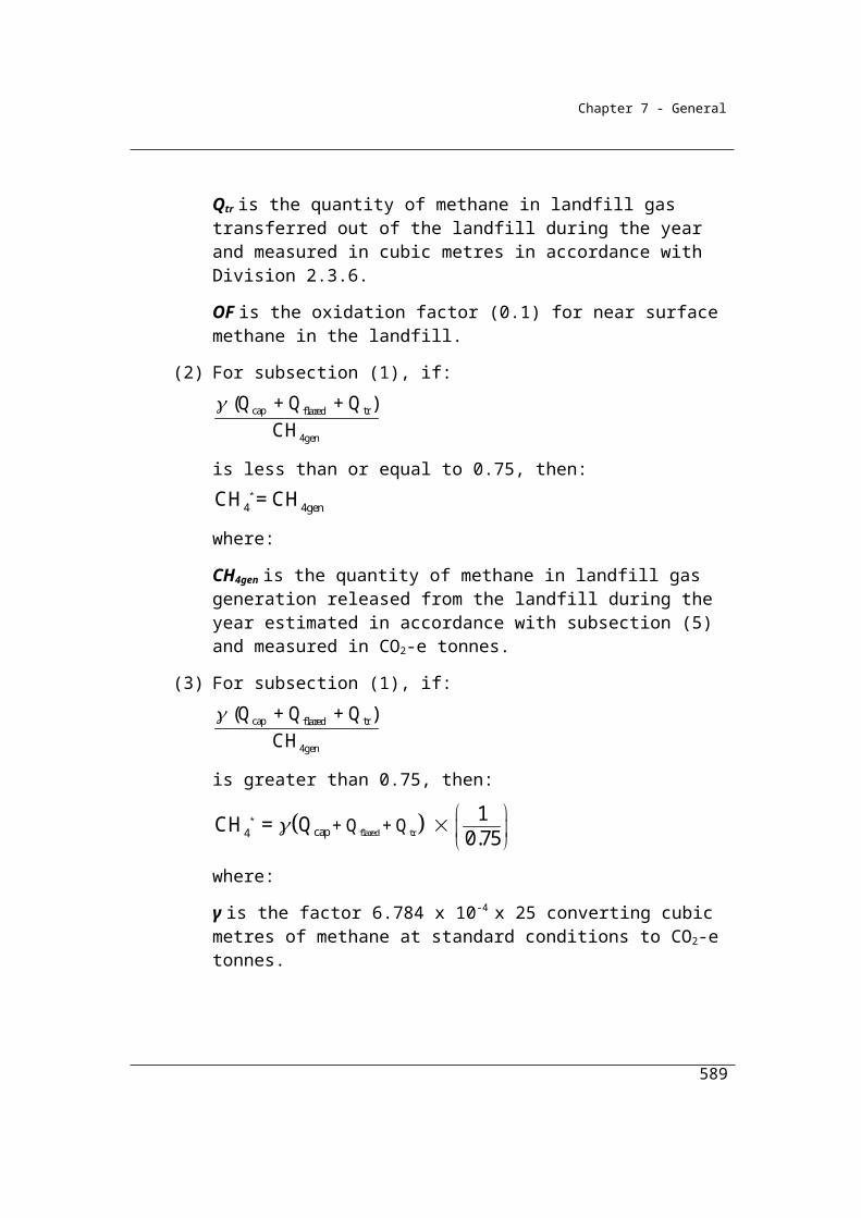
Appendices
Appendix D: References
Chapter 1 General
American Petroleum Institute, Compendium of Greenhouse Gas Emissions Methodologies for the Oil and Natural Gas Industry, August 2009. (s1.8)
Australian Coal Association Research Program, Guidelines for the Implementation of NGER Method 2 or 3 for Open Cut Coal Mine Fugitive GHG Emissions Reporting (C20005), December 2011. (s1.8)
Commission of the European Communities, Commission Decision establishing guidelines for the monitoring and reporting of greenhouse gas emissions pursuant to Directive 2003/87/EC of the European Parliament and of the Council. Brussels, 2006. (s1.20)
Commonwealth of Australia, Clean Energy Act 2011.
Commonwealth of Australia, Clean Energy Regulations 2011.
Department of Department on the Environment, National Inventory Report, 2013. (ss1.13)
Department of Climate Change and Energy Efficiency, National Greenhouse Energy and Reporting (Measurement) Technical Guidelines 2012, (s1.8)
Department of Environment and Heritage, National Pollutant Inventory – Emission Estimation Manual for Fossil Fuel Electric Power Generation, Version 2.4, March 2005. (s1.20)
589
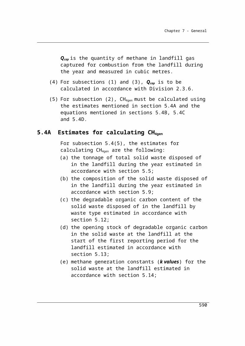
Appendices
Environmental Protection Agency, Load Calculation Protocol for use by holders of NSW environment protection licenses when calculating assessable pollutant loads. Department of Environment and Conservation (NSW), February 2005. (s1.20)
Intergovernmental Report on Climate Change (1997), 1996 IPCC Guidelines for National Greenhouse Gas Inventories; Japan. (s1.10)
Geoscience Australia, The Australian Geological Provinces Database can be obtained at: http://www.ga.gov.au/.
Intergovernmental Panel on Climate Change (IPCC), The Physical Science Basis, 2007.
International Organization for Standardization, ISO Guide 34: General requirements for the competence of reference material producers, 2000. (ss1.34 (4))
International Organization for Standardization, ISO 10012 Measurement management systems – Requirements for measurement processes and measuring equipment, 2003. (s1.23)
International Organization for Standardization, ISO 10780 Stationary source emissions – Measurement of velocity and volume of gas streams in ducts, 1994. (s1.24)
International Organization for Standardization, ISO 10396 Stationary source emissions – Sampling for the automated determination of gas emission concentration, 2007. (s1.23)
International Organization for Standardization, ISO 12039 Stationary source emissions – Determination of carbon monoxide, carbon dioxide and oxygen –
590

Appendices
Performance characteristics and calibration of automated measuring systems, 2001. (s1.25)
International Organization for Standardization, ISO 14164 Stationary source emissions – Determination of the volume flowrate of gas streams in ducts – Automated method, 1999. (s1.24)
Mark, M., Worrall, R., Mallett, C., and Xue, S. (2001). Measuring and Reporting Greenhouse Gas Emissions. ACARP Project C8061. CSIRO Exploration and Mining Report 805C. (s1.21)
National Greenhouse and Energy Reporting Act 2007 (ss1.3 (1))
National Measurement Act 1960 (ss1.15 (4))
NIST/SEMATECH e-Handbook of Statistical Methods, http://www.itl.nist.gov/div898/handbook/, 23 April 2009
Standards Australia, AS 4323.1 Stationary source emissions – Selection of sampling positions (s1.23), 1995.
Standards Australia, AS 4323[1].1 Amdt 1 Stationary source emissions – Selection of sampling positions, 1995. (s1.23)
U.S. Environmental Protection Agency. 2003. Code of Federal Regulations: Standards of Performance for New Stationary Sources. Appendix A – Test Methods. 40 CFR 60 Appendix A. Washington, D.C. (s1.20)
– Method 1 – Sample and velocity traverses for stationary sources. (s1.23)
– Method 2 – Determination of stack velocity and volumetric flow rate (Type S Pitot tube) (2000). (s1.24)
591
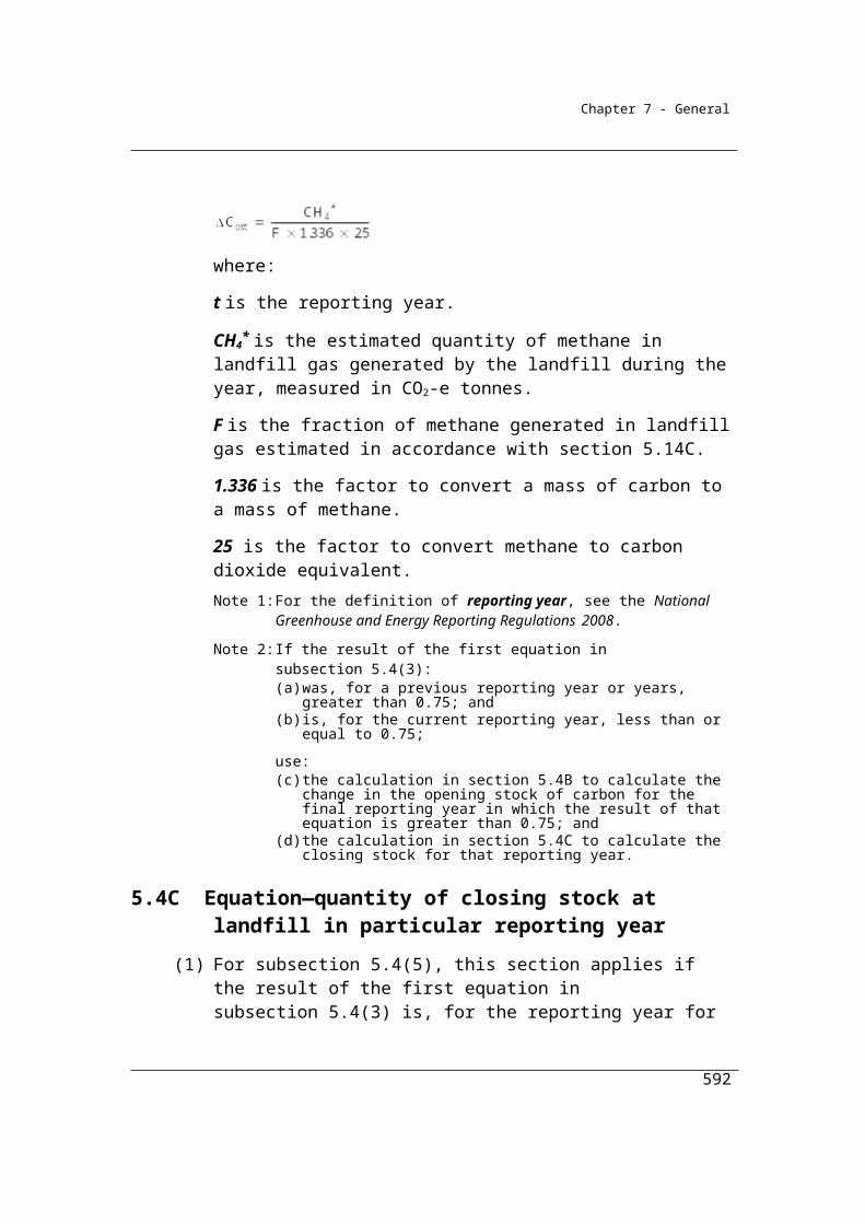
Appendices
– Method – 02A Direct measurement of gas volume through pipes and small ducts (2000). (s1.24)
– Method – 03A Determination of oxygen and carbon dioxide concentrations in emissions from stationary sources (Instrumental analyser procedure) (2006). (s1.25)
– Method – 03C Determination of carbon dioxide, methane, nitrogen and oxygen from stationary sources (1996). (s1.25)
U.S. Environmental Protection Agency. 2009. Code of Federal Regulations: Proposed Rule; Mandatory Reporting of Greenhouse Gases; 40 CFR Parts 86, 87, 89, et al., Washington, D.C. (s1.4)
West Australian Department of Environment and Conservation, Department of Environment and Conservation Continuous Emissions Monitoring System (CEMS) Code for Stationary Source Air Emissions, October 2006. (s1.20)
World Resources Institute/World Business Council on Sustainable Development, GHG Protocol guidance on uncertainty assessment in GHG inventories and calculating statistical parameter uncertainty. World Resources Institute and the World Business Council on Sustainable Development. September 2003 v1.0. (s1.8)
Chapter 2 Fuel Combustion
Australian Bureau of Agriculture and Resource Economics (ABARE1), Fuel and Electricity Survey – Fuel Codes, Commonwealth of Australia, Canberra, 2007.
ABARE2, Energy in Australia 2006, produced for Department of Industry, Tourism and Resources, Commonwealth of Australia, Canberra, 2007, pages 77-79.
592

Appendices
Australian Greenhouse Office, Technical Guidelines - Generator Efficiency Standards. Department of Environment and Heritage, December 2006
American Gas Association, AGA Report No. 3, Orifice Metering of Natural Gas Part 1: General Equations & Uncertainty Guidelines (1990, 2003). (2.32 (4a))
American Gas Association, AGA Report No. 3, Orifice Metering of Natural Gas Part 2: Specification and Installation Requirements (2000, 2003). (2.32 (4a))
American Gas Association, AGA Report No. 3, Orifice Metering of Natural Gas Part 3: Natural Gas Applications (1992). (2.32 (4a))
American Gas Association, AGA Report No. 3, Orifice Metering of Natural Gas Part 4: Background, Development, Implementation Procedures and Subroutine Documentation (1992). (2.32 (4a))
American Gas Association, AGA Report No. 7, Measurement of natural gas by turbine meters (2006). (ss2.32 (4b))
American Gas Association, AGA Report No. 8, Compressibility Factor of Natural Gas and Related Hydrocarbon Gases (1994). (ss1.19l)
American Gas Association, AGA Transmission Measurement Committee Report No. 8: Compressibility Factors of Natural Gas and Other Related Hydrocarbon Gases (2003). (ss2.33 (2))
American National Standards Institute, ANSI B109.3 Rotary-Type Gas Displacement Meters, 2000. (ss2.32 (4c)
American Petroleum Institute, Compendium of Greenhouse Gas Emissions Estimation Methodologies for the Oil and Gas Industry, 2004 (s2.56 (2))
593

Appendices
American Petroleum Institute, Manual of Petroleum Measurement Standards Part 1: General Equations & Uncertainty Guidelines (1990) (reaffirmed 2003). (2.32 (4a))
American Petroleum Institute, Manual of Petroleum Measurement Standards Part 2: Specification and Installation Requirements (2000) (reaffirmed 2006). (2.32 (4a))
American Petroleum Institute, Manual of Petroleum Measurement Standards Part 3: Natural Gas Applications (1992) (reaffirmed 2003). (2.32 (4a))
American Petroleum Institute, Manual of Petroleum Measurement Standards Part 4: Background, Development, Implementation Procedures and Subroutine Documentation (1992) (reaffirmed 2006). (2.32 (4a))
ASTM International, ASTM D240–02 Standard test method for heat of combustion of liquid hydrocarbon fuels by bomb calorimeter, 2007. (ss2.45 (1))
ASTM International, ASTM D1265–05 Standard Practice for Sampling Liquefied Petroleum (LP) Gases (Manual Method), 2005. (2.47 (3))
ASTM International, ASTM D1298–99 Ed 2 Standard test method for density, relative density (specific gravity), or API gravity of crude petroleum and liquid petroleum products by hydrometer method, 1999. (ss2.45 (1))
ASTM International, ASTM D1657 – 02 Standard Test Method for Density or Relative Density of Light Hydrocarbons by Pressure Hydrometer, 2007. (ss2.45 (1))
ASTM International, ASTM D1826 – 94 Standard test method for calorific (heating) value of gases in natural gas range by continuous recording calorimeter, 2003. (ss2.24 (1))
ASTM International, ASTM D1945 – 03 Standard test method for analysis of natural gas by gas chromatography, 2003. (ss2.24 (1))
594
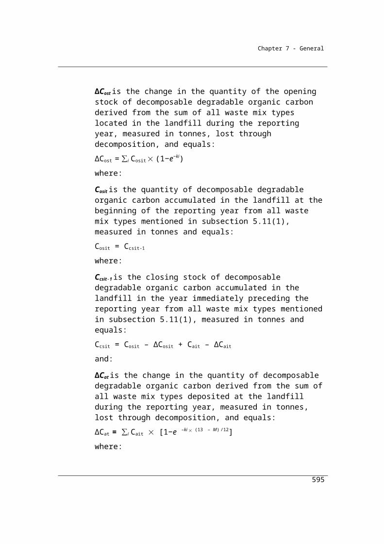
Appendices
ASTM International, ASTM D 1946 – 90 Standard practice for analysis of reformed gas by gas chromatography, 2006. (ss2.24 (1))
ASTM International, ASTM D3588 – 98 Standard practice for calculating heat value, compressibility factor, and relative density of gaseous fuels, 2003. (ss2.24 (1))
ASTM International, ASTM D4052 – 96 e1 Standard Test Method for Density, Relative Density, and API Gravity of Liquids by Digital Density Meter, 2002. (ss2.45 (1))
ASTM International, ASTM D4057– 06 Standard Practice for Manual Sampling of Petroleum and Petroleum Products, 2006. (2.47 (3))
ASTM International, ASTM D4177–95 Standard Practice for Automatic Sampling of Petroleum and Petroleum Products, 2005. (2.47 (3))
ASTM International, ASTM D4809–06 Standard test method for heat of combustion of liquid hydrocarbon fuels by bomb calorimeter (precision method), 2006. (ss2.45 (1))
ASTM International, ASTM D 4916 – 04 Standard Practice for Mechanical Auger Sampling, 2004. (2.15 (3))
ASTM International, ASTM D5002 – 99 Standard Test Method for Density and Relative Density of Crude Oils by Digital Density Analyzer, 2005. (ss2.45 (1))
ASTM International, ASTM D5287 – 97 Standard Practice for Automatic Sampling of Gaseous Fuels, 2002. (2.26 (3))
595
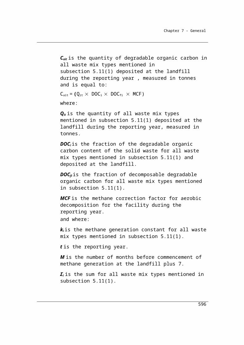
Appendices
ASTM International, ASTM D5291– 02 Standard test methods for instrumental determination of carbon, hydrogen, and nitrogen in petroleum products and lubricants, 2002. (ss2.45 (1))
ASTM International, ASTM D5503 – 94 Standard Practice for Natural Gas Sample-Handling and Conditioning Systems for Pipeline Instrumentation, 2003. (2.26 (3))
ASTM International, ASTM D6347/D6347M – 99 Standard Test Method for Determination of Bulk Density of Coal Using Nuclear Backscatter Depth Density Methods, 1999. (2.15 (3))
ASTM International, ASTM D6866.08 – Determining the Bio-based Content of Solid, Liquid and Gaseous Samples Using Radiocarbon Analysis, 2008. (ss2.66 (1b) and s2.67)
ASTM International, ASTM D7164 – 05 Standard practice for on-line/at-line heating value determination of gaseous fuels by gas chromatography, 2005. (ss2.24 (1))
ASTM International, ASTM F307 – 02 Standard Practice for Sampling Pressurized Gas for Gas Analysis, 2007. (2.26 (3))
Commonwealth of Australia, Customs Act 1901.
Department of Department on the Environment, National Inventory Report, 2013. (ss2.4)
European Committee for Standardization, CEN/TS 15400 Solid Recovered Fuels – Methods for the Determination of Calorific Value, 2006.
European Committee for Standardization, CEN/TS 15403 Solid Recovered Fuels – Methods for the Determination of ash Content, 2006.
596
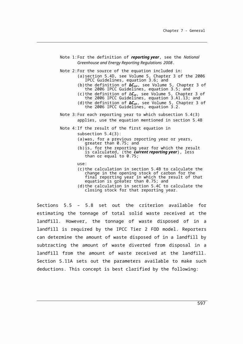
Appendices
European Committee for Standardization, CEN/TS 15407 Solid Recovered Fuels – Method for the Determination of Carbon (c), Hydrogen (h) and Nitrogen (N) content, 2006.
European Committee for Standardization, CEN/TS 15414 – 3 Solid Recovered Fuels – Determination of Moisture Content Using the Oven dry Method, 2006.
European Committee for Standardization, CEN TS 15440 Solid Recovered Fuels – Method for the Determination of Biomass Content, 2006. (ss2.66 (1b))
European Committee for Standardization, CEN/TS 15442 Solid recovered fuels – Methods for sampling, 2006. (ss2.12 (3))
European Committee for Standardization, CEN/TS 14778 – 1 Solid Biofuels – Sampling – Part 1– Methods for Sampling, 2005. (ss2.12 (3))
Gas Processors Association, GPA 2145 – 03 Table of Physical Constants for Hydrocarbons & Other Compounds of Interest to the Natural Gas Industry, 2003. (ss2.24 (1))
Gas Processors Association, GPA 2166 – 05 Obtaining Natural Gas Samples for Analysis by Gas Chromatography, 2005. (ss2.12 (3))
Gas Processors Association, GPA 2172 – 96 Calculation of Gross Heating Value, Relative Density, and Compressibility of Natural Gas Mixtures from Compositional Analysis, 1996. (ss2.24 (1))
Gas Processors Association, GPA 2261 – 00 Analysis for Natural Gas & Similar Gaseous Mixtures by Gas Chromatography, 2000. (ss2.24 (1))
597

Appendices
Independent Pricing and Regulatory Tribunal, Notice from the Greenhouse Gas Abatement Scheme (GGAS) scheme administrator - Determining the energy content of waste methane under the generation rules, December 2006.
Intergovernmental Panel on Climate Change, IPCC 2006, 2006 IPCC Guidelines for National Greenhouse Gas Inventories, Volume 2 Energy. Prepared by the National Greenhouse Gas Inventories Programme. Published: IGES, Japan. (2.27 (2))
International Organization for Standardization, ISO 3170 Petroleum liquids – Manual sampling, 2004. (2.47 (3)) International Organization for Standardization, ISO 3171 Petroleum liquids – Automatic pipeline sampling, 1988. (2.47 (3))
International Organization for Standardization, ISO 4257 Liquefied petroleum gases — Method of sampling, 2001. (2.47 (3))
International Organization for Standardization, ISO 6578 Refrigerated hydrocarbon liquids - Static measurement - Calculation procedure, 1991. (ss2.45 (1))
International Organization for Standardization, ISO 6974 – 1: Natural gas – Determination of composition with defined uncertainty by gas chromatography. Part 1: Guidelines for tailored analysis, 2000. (ss2.24 (1))
International Organization for Standardization, ISO 6974 – 2: Natural gas – Determination of composition with defined uncertainty by gas chromatography. Part 2: Measuring–system characteristics and statistics for processing of data, 2001. (ss2.24 (1))
International Organization for Standardization, ISO 6974 – 3: Natural gas – Determination of composition with defined uncertainty by gas chromatography. Part
598
Appendices
3: Determination of hydrogen, helium, oxygen, nitrogen, carbon dioxide and hydrocarbons up to C8 using two packed columns, 2000. (ss2.24 (1))
International Organization for Standardization, ISO 6974 – 4: Natural gas – Determination of composition with defined uncertainty by gas chromatography. Part 4: Determination of nitrogen, carbon dioxide and C1 to C5 and C6+ hydrocarbons for a laboratory and on-line measuring system using two columns, 2000. (ss2.24 (1))
International Organization for Standardization, ISO 6974 – 5: Natural gas – Determination of composition with defined uncertainty by gas chromatography. Part 5: Determination of nitrogen, carbon dioxide and C1 to C5 and C6+ hydrocarbons for a laboratory and on-line process application using three columns, 2000. (ss2.24 (1))
International Organization for Standardization, ISO 6974 – 6: Natural gas – Determination of composition with defined uncertainty by gas chromatography. Part 6: Determination of hydrogen, helium, oxygen, nitrogen, carbon dioxide and C1 to C8 hydrocarbons using three capillary columns, 2002. (ss2.24 (1))
International Organization for Standardization, ISO 6975 Natural gas – Extended analysis – Gas-chromatographic method, 1997. (ss2.24(3))
International Organization for Standardization, ISO 6976: Natural gas – Calculation of calorific values, density, relative density and Wobbe index from composition, 1995. (ss2.24 (1))
International Organization for Standardization, ISO 6976: Cor 2 Natural gas - Calculation of calorific values, density, relative density and Wobbe index from composition, 1997. (ss2.24 (1))
International Organization for Standardization, ISO 6976: Cor 3 Natural gas - Calculation of calorific values, density, relative density and Wobbe index from composition, 1999. (ss2.24 (1))
599

Appendices
International Organization for Standardization, ISO 7941 Commercial propane and butane – Analysis by gas chromatography, 1988. (ss2.45 (1))
International Organization for Standardization, ISO 8943 Refrigerated light hydrocarbon fluids – Sampling of liquefied natural gas – Continuous and intermittent methods, 2007. (2.26 (3))
International Organization for Standardization, ISO 10715 Natural gas – Sampling guidelines, 1997. (2.26 (3))
International Organization for Standardization, ISO 10723 Natural gas – Performance evaluation of on-line analytical systems, 2011. (ss1.10e)
Commonwealth of Australia, National Greenhouse and Energy Reporting Regulations 2008
Commonwealth of Australia, National Measurement Act 1960 (ss2.32 (6))
Standards Australia, AS 1038.1 Coal and coke – Analysis and testing – Higher rank coal – Total moisture (supersedes 1038.1 – 1992), 2001.
Standards Australia, AS1038.2 Coal and coke – Analysis and testing – coke – total moisture, 2002.
Standards Australia, AS 1038.3 Coal and coke – Analysis and testing – Proximate analysis of higher rank coal, 2000.
Standards Australia, AS 1038.5 Coal and coke – Analysis and testing - Gross calorific value, 1998.
600

Appendices
Standards Australia, AS 1038.6.1 Coal and coke – Analysis and testing – Higher rank coal and coke – Ultimate analysis – Carbon and hydrogen, 1997.
Standards Australia, AS 1038.6.4 Coal and coke – Analysis and testing – Higher rank coal and coke – Ultimate analysis – Carbon, hydrogen and nitrogen – Instrumental method, 2005.
Standards Australia, AS 2434.1 Methods for the analysis and testing of lower rank coal and its chars –Determination of the total moisture content of lower rank coal, 1999.
Standards Australia, AS 2434.6 Methods for the analysis and testing of lower rank coal and its chars – Lower rank coal – Ultimate analysis – Classical methods (supersedes AS2434.6.1-1986), 2002.
Standards Australia, AS 2434.8 Methods for the analysis and testing of lower rank coal and its chars – Lower rank coal – Determination of ash (supersedes AS2434.8 – 1993), 2002.
Standards Australia, AS 3583.2 Methods of test for supplementary cementitious materials for use with portland cement. Method 2: Determination of moisture content, 1991. (s2.9)
Standards Australia, AS 3583.3 Methods of test for supplementary cementitious materials for use with portland cement. Method 3: Determination of loss on ignition, 1991. (s2.9)
Standards Australia, AS 4264.4 Coal and coke – Sampling – Determination of precision and bias, 1996. (ss2.7 (4))
Standards Australia, AS 4323.1 Stationary source emissions – Selection of sampling positions, 1995. (s2.11)
601

Appendices
Standards Australia, AS 4323[1].1 Amdt 1 Stationary source emissions – Selection of sampling positions, 1995. (s2.11)
Standards Australia, AS 4323.2 Stationary source emissions – Determination of total particulate matter – Isokinetic manual sampling – Gravimetric method, 1995. (s2.11)
Standards Australia, AS ISO/IEC – 17025: General requirements for the competence of testing and calibration laboratories, 2005. (ss2.8 (3))
Standards Australia, AS ISO/IEC – 17025: General requirements for the competence of testing and calibration laboratories – Technical Corrigendum 1, 2005. (ss2.8 (3))
Standards Australia, AS 4264.1 Coal and coke – Sampling – Higher rank coal – Sampling procedure, 1995. (ss2.12 (3)
Standards Australia, AS 4264.2 Coal and coke – Sampling – Coke – Sampling procedures, 1996. (ss2.12 (3)
Standards Australia, AS 4264.3 Coal and coke – Sampling – Lower rank coal – Sampling procedures, 1996. (ss2.12 (3)
Standards New Zealand, NZS 5259 Gas Measurement, 2004. (ss2.32 (5))
World Business Council for Sustainable Development / World Resources Institute, Allocation of Emissions from a Combined Heat and Power (CHP) Plant – Guide to calculation worksheets (September 2006) v1.0. (ss2.70 (2))
Chapter 3 Fugitive emissions from fuels
602
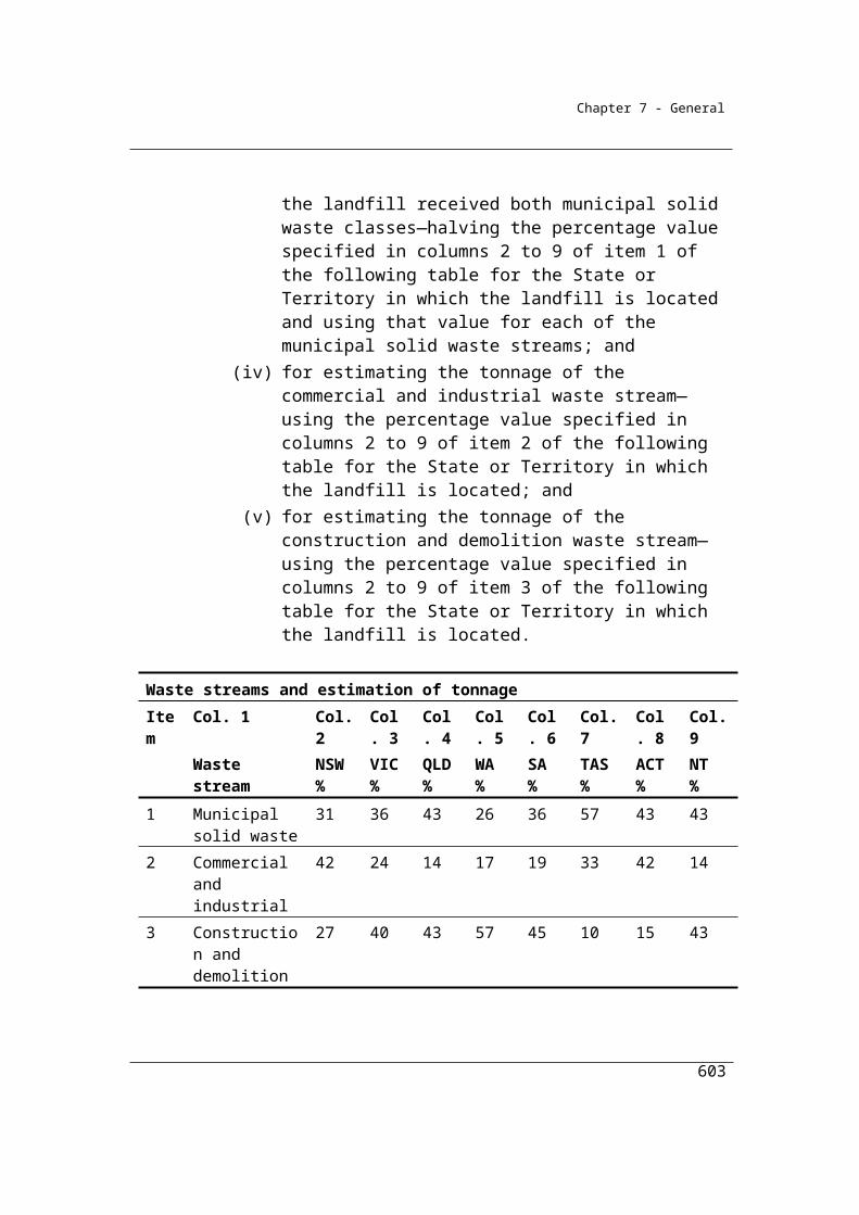
Appendices
Australian Coal Association Research Program, Guidelines for the Implementation of NGER Method 2 or 3 for Open Cut Coal Mine Fugitive Emissions Reporting (C20005), December 2011. (s1.8)
American Petroleum Institute, Compendium of Greenhouse Gas Emissions Estimation Methodologies for the Oil and Natural Gas Industry, August 2009.
American Petroleum Institute, Compendium of Greenhouse Gas Emissions Estimation Methodologies for the Oil and Gas Industry, 2005.
Coal Mine Health and Safety Act 2002(NSW) (s3.9)
Coal Mine Health and Safety Regulation 2006(NSW) (s3.9)
Coal mining safety and health Act 1999(QLD) (s3.9)
Coal mining safety and health regulation 2001(QLD) (s3.9)
Department on the Environment, National Inventory Report, 2013. (ss3.17,3.2.3.2,3.32, 3.33,3.5)
Intergovernmental Panel on Climate Change, IPCC 2006, 2006 IPCC Guidelines for National Greenhouse Gas Inventories, Volume 2 Energy. Prepared by the National Greenhouse Gas Inventories Programme. Published: IGES, Japan.
Joint Ore Reserves Committee, The Australian code for reporting of exploration results, mineral resources and ore reserves. The Joint Ore Reserves Committee (JORC) Code, 2004 edition
Joint Ore Reserves Committee, Australian Guidelines for Estimating and Reporting of Inventory Coal, Coal Resources and Coal Reserves. Prepared by the Coalfields Geology Council of NSW and the Queensland Mining Council, 2003.
603

Appendices
Saghafi, A. (2008), Evaluating a tier 3 method for estimating fugitive emissions from open cut mining. Joint Research Project ACARP (C15076) and CSIRO. CSIRO Investigation Report ET/IR 1011.
International Organization for Standardization, ISO 10780 Stationary source emissions – Measurement of velocity and volume of gas streams in ducts, 1994. (s3.10)
International Organization for Standardization, ISO 14164 Stationary source emissions – Determination of the volume flowrate of gas streams in ducts – Automated method, 1999. (s3.10)
Standards Australia, AS 2519 Guide to the technical evaluation of higher rank coal deposits, 1993. (s3.25)
Standards Australia, AS 2617 Sampling from coal seams, 1996. (s3.26)
Standards Australia, AS 3980 Guide to the determination of gas content of coal – Direct desorption method, 1999. (s3.25)
Standards Australia, AS 4323.1 Stationary source emissions – Selection of sampling positions, 1995. (s3.9)
Standards Australia, AS 4323[1].1 Amdt 1 Stationary source emissions – Selection of sampling positions, 1995. (s3.9)
U.S. Environmental Protection Agency. 2003. Code of Federal Regulations: Standards of Performance for New Stationary Sources. Appendix A – Test Methods. 40 CFR 60 Appendix A. Washington, D.C. (s1.20)
– Method 1 – Sample and velocity traverses for stationary sources. (s1.23)
604
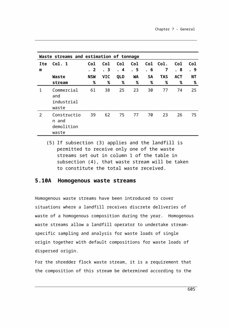
Appendices
– Method 2 – Determination of stack velocity and volumetric flow rate (Type S Pitot tube) (2000). (s3.10)
– Method – 02A Direct measurement of gas volume through pipes and small ducts (2000). (s3.10)
– Method – 03C Determination of carbon dioxide, methane, nitrogen and oxygen from stationary sources (1996). (s3.11)
Chapter 4 Industrial Processes Emissions
ASTM International, ASTM C25-06, Standard Test Methods for Chemical Analysis of Limestone, Quicklime, and Hydrated Lime. (ss4.15 (1))
ASTM International, ASTM C50-00 (2006), Standard Practice for Sampling, Sample Preparation, Packaging, and Marking of Lime and Limestone Products. (ss4.15 (1))
Department on the Environment, National Inventory Report, 2013. (ss4.4, 4.13)
Energy Networks Australia, ENA Industry Guideline for SF6 Management, 2008. (ss4.103)
IPCC 2006, 2006 IPCC Guidelines for National Greenhouse Gas Inventories, Volume 3 Industrial process and product use. Prepared by the National Greenhouse Gas Inventories Programme, Eggleston H.S., Buendia L., Miwa K., Ngara T., and Tanabe K. (eds). Published: IGES, Japan. (ss4.7 (2))
Standards Australia, AS 4264.4 Coal and coke – Sampling – Determination of precision and bias, 1996. (ss4.15 (4))
605

Appendices
Standards Australia, AS 4489.0–1997 Test methods for limes and limestones — General introduction and list of methods. (ss4.15 (1))
US EPA, International Aluminium Institute (2003), Protocol for Measurement of Tetrafluoromethane (CF4) and Hexafluoroethane (C2F6) Emissions from Primary Aluminium Production. (s4.86)
Chapter 5 Waste
American Public Health Association, 1995. Standard methods for the examination of water and waste water. 19th Edition, American Public Health Association, USA.
– Section 4500-Norg B– Section 4500-Norg C– Section 4500-Norg D– Section 5210 B– Section 5220 B– Section 5220 C– Section 5220 D
American Society for Testing and Materials, ASTM 5231-92 Standard Test Method
for Determination of the Composition of Unprocessed Municipal Solid Waste, 2008.
(ss5.11 (2))
Bureau of Meteorology, Climate statistics for Australian locations. Available from: http://www.bom.gov.au/climate/cdo/about/about-stats.shtml.
Bureau of Meteorology, Climate statistics for Australian locations. Available from: http://www.bom.gov.au/climate/cdo/about/about-stats.shtml
Environment Agency of the United Kingdom, Guidance on monitoring landfill gas surface emissions, September 2004, (s5.17F, s5.17G, 5.17H, 5.17J
606

Appendices
Department of Climate Change and Energy Efficiency, Technical Guidelines for the estimation of greenhouse gas emissions by facilities in Australia, July 2012. (s5.17)
European Committee for Standardization, EN 13342 Characterization of sludges - Determination of kjeldahl nitrogen, 2000. (ss5.34 (2))
International Organization for Standardization, ISO 5667-13-1997 Water quality - Sampling - Part 13- Guidance on sampling of sludges from sewage and water treatment works, 1997. (ss5.36 (3))
International Organization for Standardization, ISO 6060 Water quality – Determination of the chemical oxygen demand, 1989. (5.28 (1)
International Organization for Standardization, ISO 11905-1-1997 Water quality - Determination of nitrogen - Part 1- Method using oxidative digestion with peroxodisulfate, 1997. (ss5.34 (1))
Intergovernmental Panel on Climate Change, IPCC Guidelines for National Greenhouse Gas Inventories, Volume 5 Waste. Prepared by the National Greenhouse Gas Inventories Programme. Published: IGES, Japan, 2006. (ss5.4 (5))
Protection of the Environment Operations (General) Regulation 2009 (NSW). (ss5.31(5))
Intergovernmental Panel on Climate Change, IPCC Good Practice Guidance and Uncertainty Management in National Greenhouse Gas Inventories, Volume 5 Waste. Prepared by the National Greenhouse Gas Inventories Programme. Published: IGES, Japan, 2000. (ss5.15 (2).
Standards Australia, AS/NZS 4323.4:2009 - Stationary source emissions - Area source sampling - Flux chamber technique, 2009. (s5.17H and s5.17J)
607
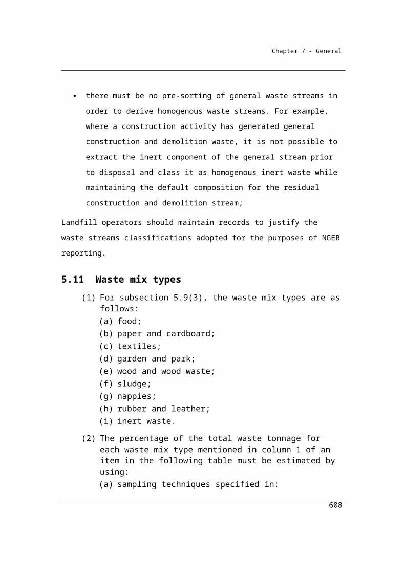
Appendices
Standards Australia, AS 4351.5 Biodegradability – Organic compounds in an aqueous medium – Determination by analysis of biochemical oxygen demand (closed bottle test), 1996. (ss5.28 (2))
Standards Australia, AS/NZS 5667.10 Water Quality – Sampling. Part 10: Guidance on sampling of waste waters, 1998. (ss5.30 (2))
U.S. Environmental Protection Agency. 2003. Code of Federal Regulations: Standards of Performance for New Stationary Sources. Appendix A – Test Methods. 40 CFR 60 Appendix A. Washington, D.C.
– Method 2E – Determination of landfill gas production flow rates (ss5.17 (2))
– Method 3C – Determination of carbon dioxide, methane, nitrogen and oxygen from stationary sources (ss5.17 (2))
Chapter 6 Energy
Australian Energy Market Commission, National Electricity Rules, Version 21, 2008.
Chapter 7 Scope 2 emissions
Department on the Environment, National Inventory Report, 2013.
World Resources Institute/World Business Council for Sustainable Development, The Greenhouse Gas Protocol: A Corporate Accounting and Reporting Standard Revised Edition, 2004.
608

Appendices
Chapter 8 Assessment of Uncertainty
Intergovernmental Panel on Climate Change, IPCC Guidelines for National Greenhouse Gas Inventories. Prepared by the National Greenhouse Gas Inventories Programme. Published: IGES, Japan, 2006.
World Resources Institute/World Business Council on Sustainable Development, GHG Protocol guidance on uncertainty assessment in GHG inventories and calculating statistical parameter uncertainty. World Resources Institute and the World Business Council on Sustainable Development. September 2003 v1.0. (ss8.3 (1))
609
