technical information lcl1, lcl2 - pepperl+fuchs
TRANSCRIPT
ISO9001
LCL1, LCL2Capacitive Limit SwitchLimit Switch for Bulk Solids
PROCESS AUTOMATION
Technical Information
With regard to the supply of products, the current issue of the following document is applicable: The General Terms of Delivery for Products and Services of the Electrical Industry, published by the Central Association of the Electrical Industry (Zentralverband Elektrotechnik und Elektroindustrie (ZVEI) e.V.) in its most recent version as well as the
supplementary clause: "Expanded reservation of proprietorship"
LCL1, LCL2
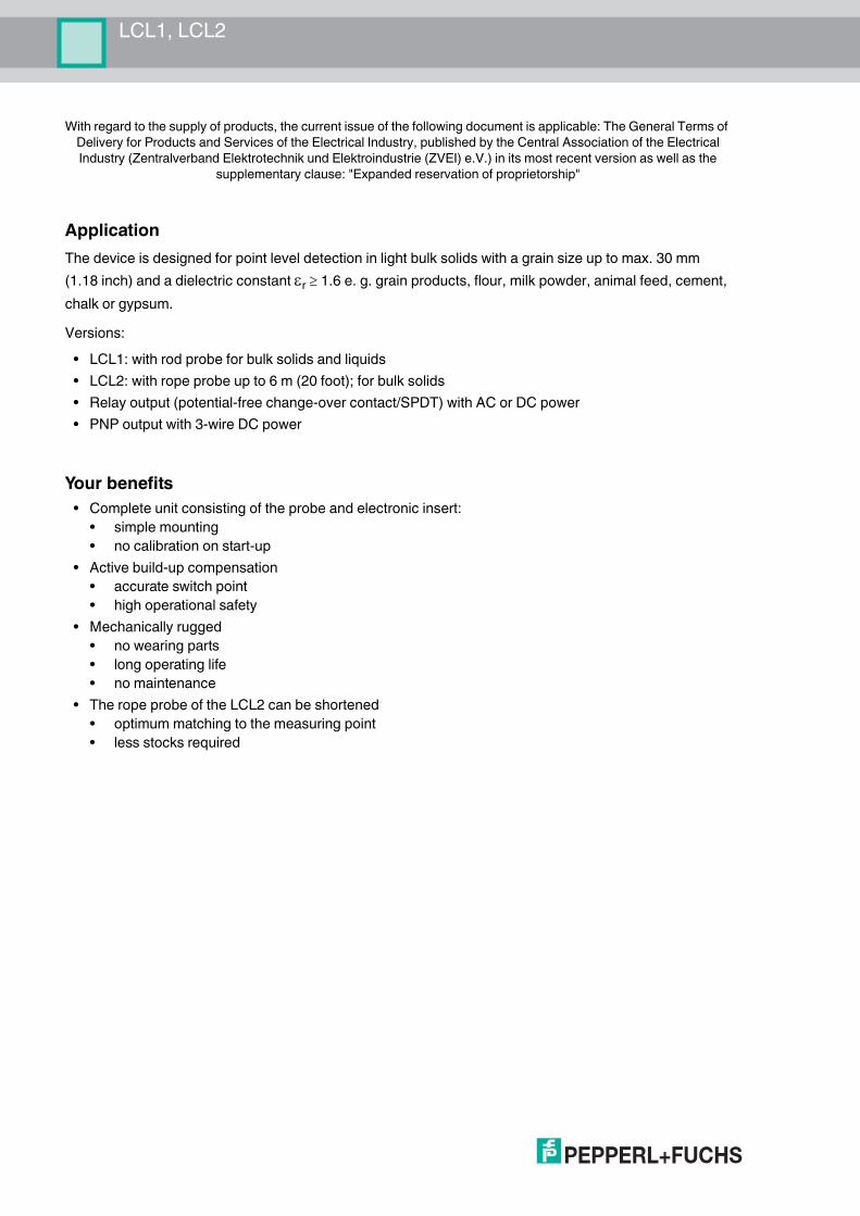
ApplicationThe device is designed for point level detection in light bulk solids with a grain size up to max. 30 mm (1.18 inch) and a dielectric constant r 1.6 e. g. grain products, flour, milk powder, animal feed, cement, chalk or gypsum.Versions:
• LCL1: with rod probe for bulk solids and liquids• LCL2: with rope probe up to 6 m (20 foot); for bulk solids• Relay output (potential-free change-over contact/SPDT) with AC or DC power• PNP output with 3-wire DC power
Your benefits• Complete unit consisting of the probe and electronic insert:
• simple mounting• no calibration on start-up
• Active build-up compensation• accurate switch point• high operational safety
• Mechanically rugged• no wearing parts• long operating life• no maintenance
• The rope probe of the LCL2 can be shortened• optimum matching to the measuring point• less stocks required
LCL1, LCL2Content
2018
-08
3
1 Function and System Design . . . . . . . . . . . . . . . . . . . . . . . . . . . . . . . . . . . . . 61.1 Measuring Principle . . . . . . . . . . . . . . . . . . . . . . . . . . . . . . . . . . . . . . . . . 61.2 Measuring System. . . . . . . . . . . . . . . . . . . . . . . . . . . . . . . . . . . . . . . . . . . 61.3 Function Range . . . . . . . . . . . . . . . . . . . . . . . . . . . . . . . . . . . . . . . . . . . . . 71.4 Setting the Sensitivity . . . . . . . . . . . . . . . . . . . . . . . . . . . . . . . . . . . . . . . . 81.5 Fail-Safe Mode . . . . . . . . . . . . . . . . . . . . . . . . . . . . . . . . . . . . . . . . . . . . . . 9
2 Input. . . . . . . . . . . . . . . . . . . . . . . . . . . . . . . . . . . . . . . . . . . . . . . . . . . . . . . . . 102.1 Measured Variable. . . . . . . . . . . . . . . . . . . . . . . . . . . . . . . . . . . . . . . . . . 102.2 Measuring Range. . . . . . . . . . . . . . . . . . . . . . . . . . . . . . . . . . . . . . . . . . . 10
3 Output . . . . . . . . . . . . . . . . . . . . . . . . . . . . . . . . . . . . . . . . . . . . . . . . . . . . . . . 113.1 Output signal . . . . . . . . . . . . . . . . . . . . . . . . . . . . . . . . . . . . . . . . . . . . . . 113.2 Signal on alarm . . . . . . . . . . . . . . . . . . . . . . . . . . . . . . . . . . . . . . . . . . . . 113.3 Switching Delay when Free or Covered . . . . . . . . . . . . . . . . . . . . . . . . 113.4 Overvoltage category . . . . . . . . . . . . . . . . . . . . . . . . . . . . . . . . . . . . . . . 113.5 Protection class . . . . . . . . . . . . . . . . . . . . . . . . . . . . . . . . . . . . . . . . . . . . 11
4 Power Supply . . . . . . . . . . . . . . . . . . . . . . . . . . . . . . . . . . . . . . . . . . . . . . . . . 124.1 Electrical Connection . . . . . . . . . . . . . . . . . . . . . . . . . . . . . . . . . . . . . . . 124.2 Supply Voltage. . . . . . . . . . . . . . . . . . . . . . . . . . . . . . . . . . . . . . . . . . . . . 134.3 Terminal Compartment . . . . . . . . . . . . . . . . . . . . . . . . . . . . . . . . . . . . . . 13
5 Performance Characteristics . . . . . . . . . . . . . . . . . . . . . . . . . . . . . . . . . . . . 145.1 Reference Operating Conditions. . . . . . . . . . . . . . . . . . . . . . . . . . . . . . 145.2 Hysteresis. . . . . . . . . . . . . . . . . . . . . . . . . . . . . . . . . . . . . . . . . . . . . . . . . 145.3 Switch Point . . . . . . . . . . . . . . . . . . . . . . . . . . . . . . . . . . . . . . . . . . . . . . . 145.4 Power Up Response . . . . . . . . . . . . . . . . . . . . . . . . . . . . . . . . . . . . . . . . 145.5 Long-term Drift. . . . . . . . . . . . . . . . . . . . . . . . . . . . . . . . . . . . . . . . . . . . . 145.6 Influence of Medium Temperature . . . . . . . . . . . . . . . . . . . . . . . . . . . . 14
2018
-08
4
LCL1, LCL2Content
6 Installation . . . . . . . . . . . . . . . . . . . . . . . . . . . . . . . . . . . . . . . . . . . . . . . . . . . 156.1 Installation Conditions . . . . . . . . . . . . . . . . . . . . . . . . . . . . . . . . . . . . . . 156.2 Installation Instructions LCL1 . . . . . . . . . . . . . . . . . . . . . . . . . . . . . . . . 156.3 Installation Instructions LCL2 . . . . . . . . . . . . . . . . . . . . . . . . . . . . . . . . 16
7 Environment . . . . . . . . . . . . . . . . . . . . . . . . . . . . . . . . . . . . . . . . . . . . . . . . . . 187.1 Ambient Temperature Range Tamb . . . . . . . . . . . . . . . . . . . . . . . . . . . . 187.2 Storage Temperature . . . . . . . . . . . . . . . . . . . . . . . . . . . . . . . . . . . . . . . 187.3 Climate Class. . . . . . . . . . . . . . . . . . . . . . . . . . . . . . . . . . . . . . . . . . . . . . 187.4 Degree of Protection. . . . . . . . . . . . . . . . . . . . . . . . . . . . . . . . . . . . . . . . 187.5 Impact Resistance. . . . . . . . . . . . . . . . . . . . . . . . . . . . . . . . . . . . . . . . . . 187.6 Vibrational Resistance . . . . . . . . . . . . . . . . . . . . . . . . . . . . . . . . . . . . . . 187.7 Operating Height . . . . . . . . . . . . . . . . . . . . . . . . . . . . . . . . . . . . . . . . . . . 187.8 Electromagnetic Compatibility . . . . . . . . . . . . . . . . . . . . . . . . . . . . . . . 18
8 Process . . . . . . . . . . . . . . . . . . . . . . . . . . . . . . . . . . . . . . . . . . . . . . . . . . . . . . 198.1 Process Temperature Tp . . . . . . . . . . . . . . . . . . . . . . . . . . . . . . . . . . . . 198.2 Process Pressure Range pp. . . . . . . . . . . . . . . . . . . . . . . . . . . . . . . . . . 198.3 Temperature Diagrams. . . . . . . . . . . . . . . . . . . . . . . . . . . . . . . . . . . . . . 19
9 Mechanical Construction . . . . . . . . . . . . . . . . . . . . . . . . . . . . . . . . . . . . . . . 209.1 Design and Dimensions . . . . . . . . . . . . . . . . . . . . . . . . . . . . . . . . . . . . . 209.2 Material . . . . . . . . . . . . . . . . . . . . . . . . . . . . . . . . . . . . . . . . . . . . . . . . . . . 219.3 Process Connections . . . . . . . . . . . . . . . . . . . . . . . . . . . . . . . . . . . . . . . 219.4 Housing, Cable Entry . . . . . . . . . . . . . . . . . . . . . . . . . . . . . . . . . . . . . . . 219.5 Tensile Strength . . . . . . . . . . . . . . . . . . . . . . . . . . . . . . . . . . . . . . . . . . . 21
10 Operability . . . . . . . . . . . . . . . . . . . . . . . . . . . . . . . . . . . . . . . . . . . . . . . . . . . 2210.1 Display Elements . . . . . . . . . . . . . . . . . . . . . . . . . . . . . . . . . . . . . . . . . . 2210.2 Operating Elements . . . . . . . . . . . . . . . . . . . . . . . . . . . . . . . . . . . . . . . . 22
11 Certificates and Approvals. . . . . . . . . . . . . . . . . . . . . . . . . . . . . . . . . . . . . . 2311.1 CE Mark . . . . . . . . . . . . . . . . . . . . . . . . . . . . . . . . . . . . . . . . . . . . . . . . . . 2311.2 Ex Approval . . . . . . . . . . . . . . . . . . . . . . . . . . . . . . . . . . . . . . . . . . . . . . . 23
LCL1, LCL2Content
2018
-08
5
12 Ordering Information. . . . . . . . . . . . . . . . . . . . . . . . . . . . . . . . . . . . . . . . . . . 2412.1 Product Structure LCL1 . . . . . . . . . . . . . . . . . . . . . . . . . . . . . . . . . . . . . 2412.2 Product Structure LCL2 . . . . . . . . . . . . . . . . . . . . . . . . . . . . . . . . . . . . . 25
13 Accessories . . . . . . . . . . . . . . . . . . . . . . . . . . . . . . . . . . . . . . . . . . . . . . . . . . 2713.1 Adapter . . . . . . . . . . . . . . . . . . . . . . . . . . . . . . . . . . . . . . . . . . . . . . . . . . . 2713.2 Rope Shortening Set . . . . . . . . . . . . . . . . . . . . . . . . . . . . . . . . . . . . . . . . 2713.3 Cover . . . . . . . . . . . . . . . . . . . . . . . . . . . . . . . . . . . . . . . . . . . . . . . . . . . . . 27
14 Documentation . . . . . . . . . . . . . . . . . . . . . . . . . . . . . . . . . . . . . . . . . . . . . . . . 28
2018
-08
6
LCL1, LCL2Function and System Design
1 Function and System Design1.1 Measuring Principle
Point Level DetectionA metal plate at the end of the probe, within the insulation, the integrated counter-electrode and the surroundings combine to form the two electrodes of a capacitor.If the probe is covered or free of process medium, the capacitance changes and the device switches.
Active Build-up CompensationThe device detects build-up on the probe and compensates for its effects so that the switch point is always observed. The effects of build-up compensation depend on:
• the thickness of the buildup on the probe,• the conductivity of the buildup,• the sensitivity setting on the electronic insert.
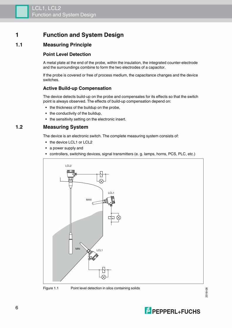
1.2 Measuring SystemThe device is an electronic switch. The complete measuring system consists of:
• the device LCL1 or LCL2• a power supply and• controllers, switching devices, signal transmitters (e. g. lamps, horns, PCS, PLC, etc.)
Figure 1.1 Point level detection in silos containing solids
LCL2
LCL1
MAX
MINLCL1
LCL1, LCL2Function and System Design
2018
-08
7
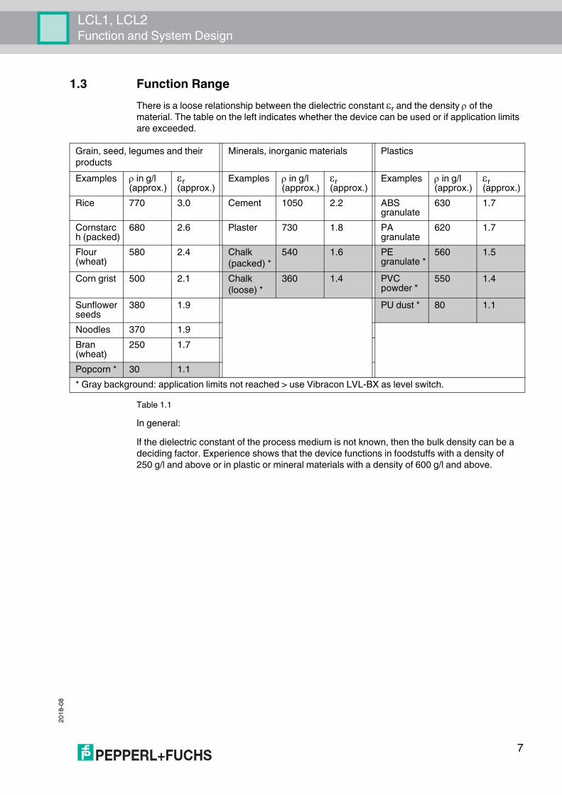
1.3 Function RangeThere is a loose relationship between the dielectric constant r and the density of the material. The table on the left indicates whether the device can be used or if application limits are exceeded.
Table 1.1In general:If the dielectric constant of the process medium is not known, then the bulk density can be a deciding factor. Experience shows that the device functions in foodstuffs with a density of 250 g/l and above or in plastic or mineral materials with a density of 600 g/l and above.
Grain, seed, legumes and their products
Minerals, inorganic materials Plastics
Examples in g/l (approx.)
r (approx.)Examples in g/l
(approx.)r (approx.)
Examples in g/l (approx.)
r (approx.)Rice 770 3.0 Cement 1050 2.2 ABS
granulate630 1.7
Cornstarch (packed)
680 2.6 Plaster 730 1.8 PA granulate
620 1.7
Flour (wheat)
580 2.4 Chalk(packed) *
540 1.6 PE granulate *
560 1.5
Corn grist 500 2.1 Chalk(loose) *
360 1.4 PVC powder *
550 1.4
Sunflower seeds
380 1.9 PU dust * 80 1.1
Noodles 370 1.9Bran (wheat)
250 1.7
Popcorn * 30 1.1* Gray background: application limits not reached > use Vibracon LVL-BX as level switch.
2018
-08
8
LCL1, LCL2Function and System Design
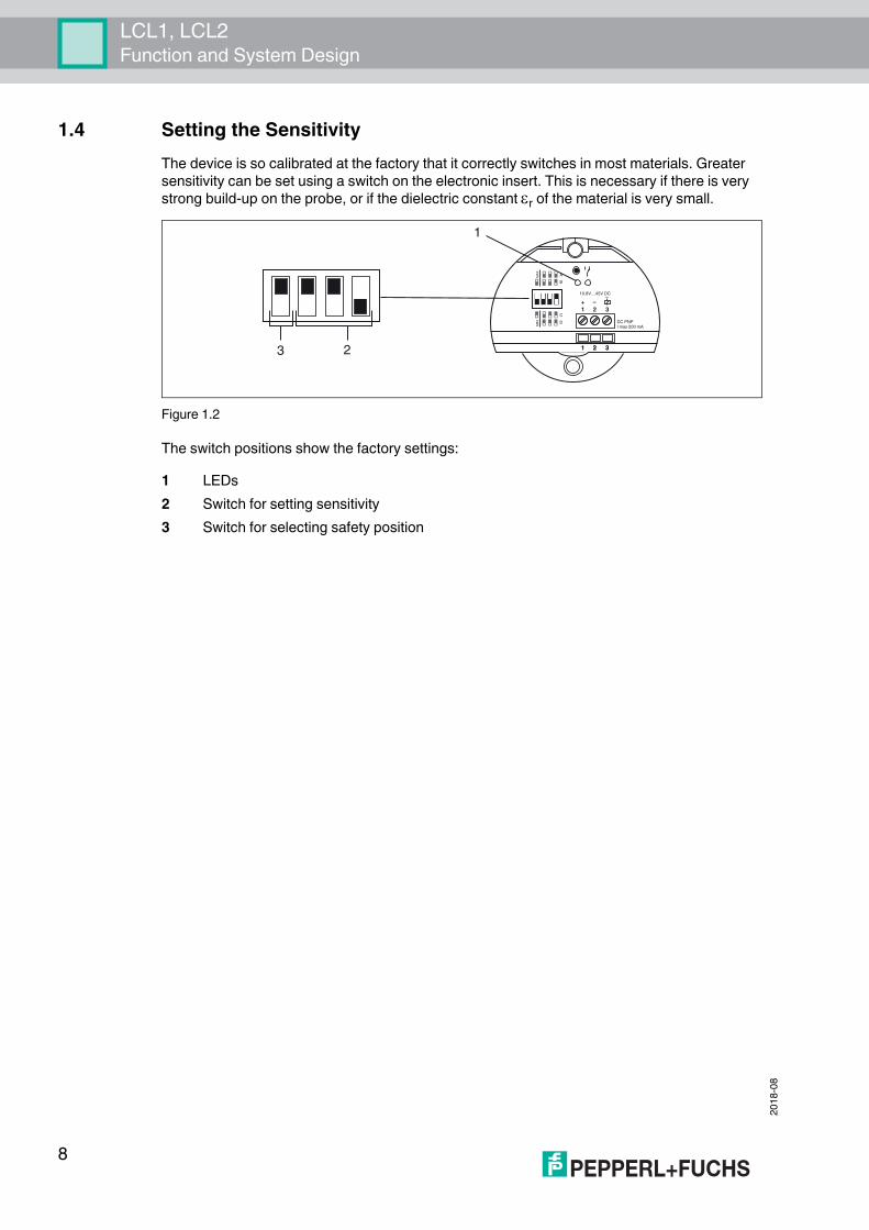
1.4 Setting the SensitivityThe device is so calibrated at the factory that it correctly switches in most materials. Greater sensitivity can be set using a switch on the electronic insert. This is necessary if there is very strong build-up on the probe, or if the dielectric constant r of the material is very small.
Figure 1.2
The switch positions show the factory settings:1 LEDs2 Switch for setting sensitivity3 Switch for selecting safety position
10.8V…45V DC
DC PNPI max 200 mA
1
1
1
+
2
2
2
– –
3
3
3
C
D
A
B
MIN
XA
M
1
23
LCL1, LCL2Function and System Design
2018
-08
9
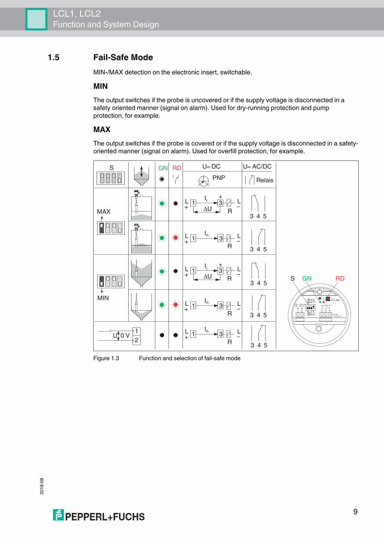
1.5 Fail-Safe ModeMIN-/MAX detection on the electronic insert, switchable.
MINThe output switches if the probe is uncovered or if the supply voltage is disconnected in a safety oriented manner (signal on alarm). Used for dry-running protection and pump protection, for example.
MAXThe output switches if the probe is covered or if the supply voltage is disconnected in a safety-oriented manner (signal on alarm). Used for overfill protection, for example.
Figure 1.3 Function and selection of fail-safe mode
MAX
GN RD U– DC…
PNP
U– AC/DC
MIN
3 4 5
3 4 5
3 4 5
3 4 5
U 0 V1
23 4 5
1+
R
R
IL
IR
U3
3
+
R
IL
U3
R
IR
3
R
IR
3
Relais
+L
–L
1
1
1
1
+L
–L
+L
–L
+L
–L
+L
–L
max. 253V 4A20V…253V AC20V…55V DC
DC PNPI max 200 mA
31L1
42N
5
FTC 262
C
D
A
B
NIM
XA
M
S GN RD
S
2018
-08
10
LCL1, LCL2Input
2 Input2.1 Measured Variable
Point level2.2 Measuring Range
• LCL1: r 1.6• LCL2: r 1.5
LCL1, LCL2Output
2018
-08
11
3 Output3.1 Output signal
• DC, PNP transistor output:Switching: PNP
• Imax 200 mA• overload and short circuit protection• residual voltage at transistor at Imax < 2.9 V
• AC/DC, Relay output: Contact: change-over, potential-freeU~max 253 V, I~max 4 AP~max 1000 VA, cos = 1P~max 500 VA, cos > 0.7I%max 4 A at U% 30 VI%max 0.2 A at U% 253 V
3.2 Signal on alarm• DC, PNP transistor output: < 100 A• AC/DC, Relay output: relay de-energized
3.3 Switching Delay when Free or Covered• LCL1: 0.5 s• LCL2: 0.8 s
3.4 Overvoltage categoryCategory II acc. to EN 61010-1
3.5 Protection classClass I acc. to EN 61010-1
2018
-08
12
LCL1, LCL2Power Supply
4 Power Supply4.1 Electrical Connection
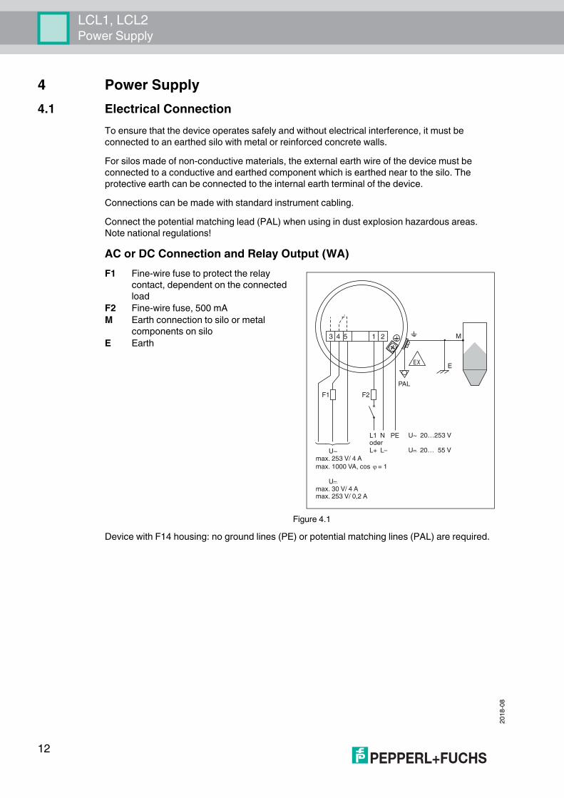
To ensure that the device operates safely and without electrical interference, it must be connected to an earthed silo with metal or reinforced concrete walls.For silos made of non-conductive materials, the external earth wire of the device must be connected to a conductive and earthed component which is earthed near to the silo. The protective earth can be connected to the internal earth terminal of the device.Connections can be made with standard instrument cabling.Connect the potential matching lead (PAL) when using in dust explosion hazardous areas. Note national regulations!
AC or DC Connection and Relay Output (WA)
Device with F14 housing: no ground lines (PE) or potential matching lines (PAL) are required.
F1 Fine-wire fuse to protect the relay contact, dependent on the connected load
Figure 4.1
F2 Fine-wire fuse, 500 mAM Earth connection to silo or metal
components on siloE Earth
L1 N
L+ L–
3 4 5 1 2
F2F1
U~ 20…253 V
U– 20… 55 V...U~max. 253 V/ 4 A
max. 1000 VA, cos = 1
U–max. 30 V/ 4 Amax. 253 V/ 0,2 A
...
PE
PAL
M
EXE
oder
LCL1, LCL2Power Supply
2018
-08
13
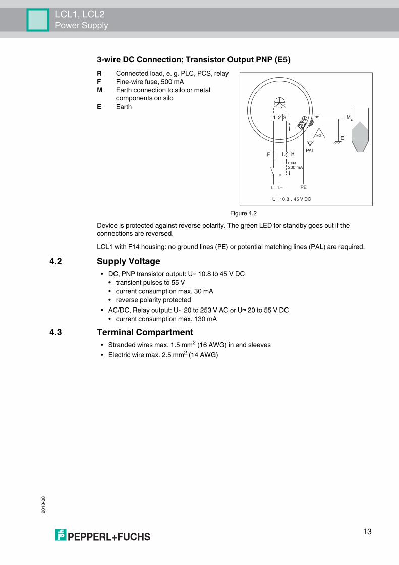
3-wire DC Connection; Transistor Output PNP (E5)
Device is protected against reverse polarity. The green LED for standby goes out if the connections are reversed.LCL1 with F14 housing: no ground lines (PE) or potential matching lines (PAL) are required.
4.2 Supply Voltage• DC, PNP transistor output: U% 10.8 to 45 V DC
• transient pulses to 55 V• current consumption max. 30 mA• reverse polarity protected
• AC/DC, Relay output: U~ 20 to 253 V AC or U% 20 to 55 V DC• current consumption max. 130 mA
4.3 Terminal Compartment• Stranded wires max. 1.5 mm2 (16 AWG) in end sleeves• Electric wire max. 2.5 mm2 (14 AWG)
R Connected load, e. g. PLC, PCS, relay
Figure 4.2
F Fine-wire fuse, 500 mAM Earth connection to silo or metal
components on siloE Earth
L+ L– PE
1 2 3
F R
max.200 mA
U 10,8…45 V DC
+
PAL
M
EXE
–
2018
-08
14
LCL1, LCL2Performance Characteristics
5 Performance Characteristics5.1 Reference Operating Conditions
In plastic container:• Ambient temperature: 23 °C (73 °F)• Medium temperature: 23 °C (73 °F)• Medium pressure pe: 0 bar (0 psi)• Medium: dielectric constant r = 2.6• Conductivity: < 1 S• Sensitivity setting: C
5.2 Hysteresis• LCL1: 4 mm (0.16 inch) horizontal, 7 mm (0.28 inch) vertical• LCL2: 5 mm (0.2 inch) vertical
5.3 Switch Point• LCL1: Probe center -5 mm (-0.2 inch) horizontal, above probe tip 40 mm (1.57 inch)
vertical• LCL2: Above probe tip: 35 mm (1.38 inch) vertical
Probe length tolerances; mm (inch):• Probe length L Tolerances• up to 1000 (39.4) +0/-10 (+0/-0.39)• up to 3000 (118) +0/-20 (+0/-0.79)• up to 6000 (236) +0/-30 (+0/-1.18)
5.4 Power Up Response• LCL1: Correct switching after max. 1.5 s• LCL2: Correct switching after max. 2 s
5.5 Long-term Drift• LCL1: 3 mm (0.12 inch) horizontal, 6 mm (0.24 inch) vertical• LCL2: Vertical 6 mm (0.24 inch)
5.6 Influence of Medium TemperatureDepending on material to be measured
LCL1, LCL2Installation
2018
-08
15
6 Installation6.1 Installation Conditions
Silo MaterialThe device can be used in a range of silos made of different materials.
Mounting PointNote the angle of the material mounds and the outlet funnel when determining the mounting point or probe length of the LCL2.
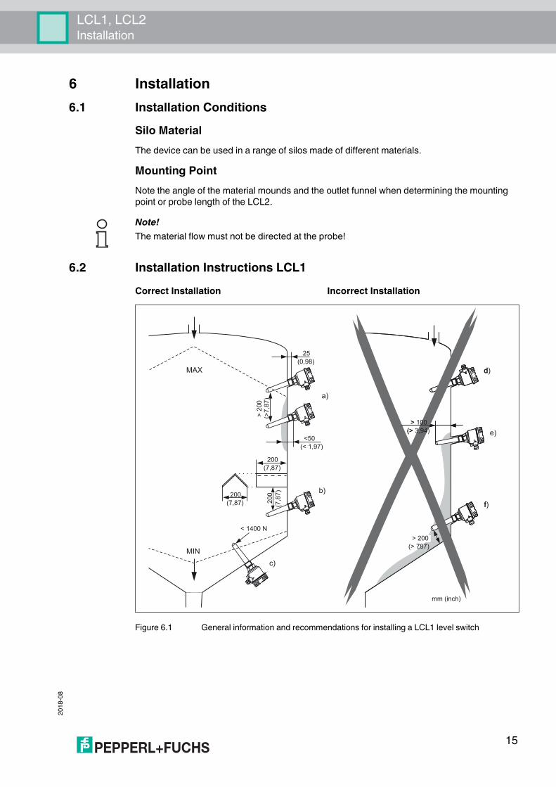
6.2 Installation Instructions LCL1
Figure 6.1 General information and recommendations for installing a LCL1 level switch
Note!The material flow must not be directed at the probe!
Correct Installation Incorrect Installation
a)
b)
c)
MAX
MIN
<50(< 1,97)
25(0,98)
> 20
0(>
7,87
)
200(7,87)
< 1400 N
e)
d)
> 200
f)200
(7,87) 200 )78,7(
mm (inch)
(> 787)
> 100(> 3,94)
2018
-08
16
LCL1, LCL2Installation
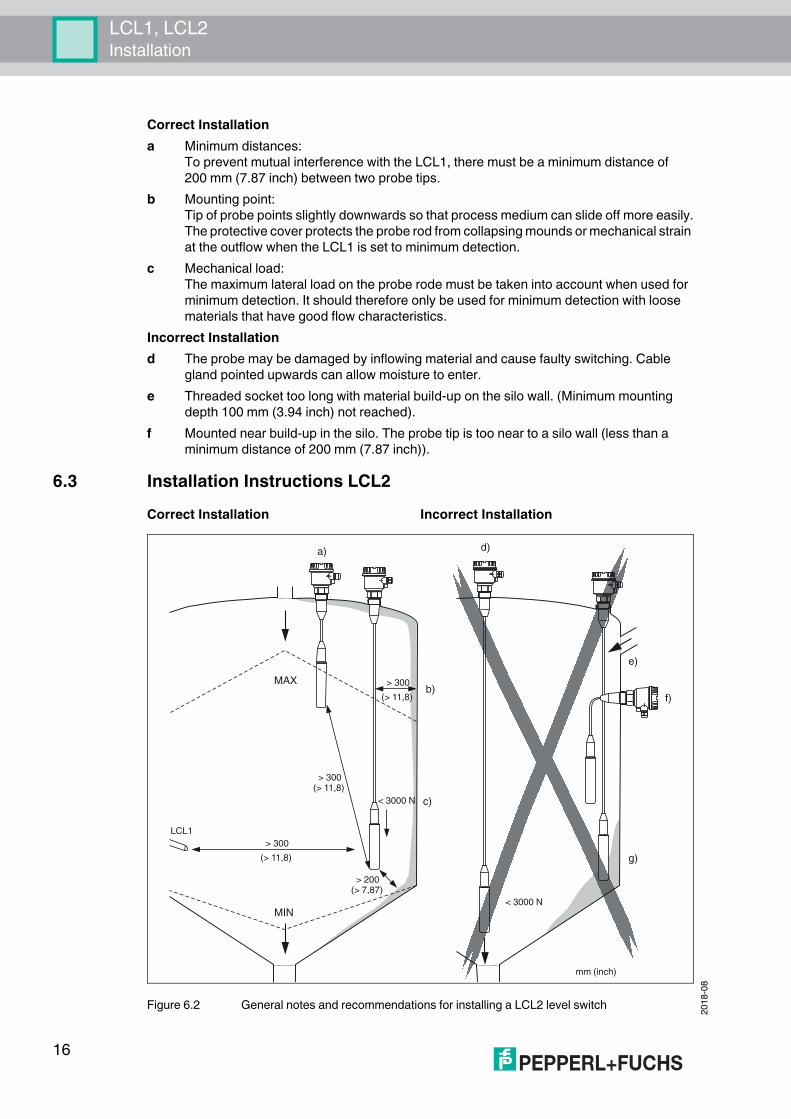
6.3 Installation Instructions LCL2
Figure 6.2 General notes and recommendations for installing a LCL2 level switch
Correct Installationa Minimum distances:
To prevent mutual interference with the LCL1, there must be a minimum distance of 200 mm (7.87 inch) between two probe tips.
b Mounting point:Tip of probe points slightly downwards so that process medium can slide off more easily.The protective cover protects the probe rod from collapsing mounds or mechanical strain at the outflow when the LCL1 is set to minimum detection.
c Mechanical load:The maximum lateral load on the probe rode must be taken into account when used for minimum detection. It should therefore only be used for minimum detection with loose materials that have good flow characteristics.
Incorrect Installationd The probe may be damaged by inflowing material and cause faulty switching. Cable
gland pointed upwards can allow moisture to enter.e Threaded socket too long with material build-up on the silo wall. (Minimum mounting
depth 100 mm (3.94 inch) not reached).f Mounted near build-up in the silo. The probe tip is too near to a silo wall (less than a
minimum distance of 200 mm (7.87 inch)).
Correct Installation Incorrect Installation
a)
c)
b)
g)
f)
e)
d)
MAX
MIN
> 300
(> 11,8)
< 3000 N
< 3000 N
LCL1
> 300(> 11,8)
> 300
(> 11,8)
> 200(> 7,87)
mm (inch)
LCL1, LCL2Installation
2018
-08
17
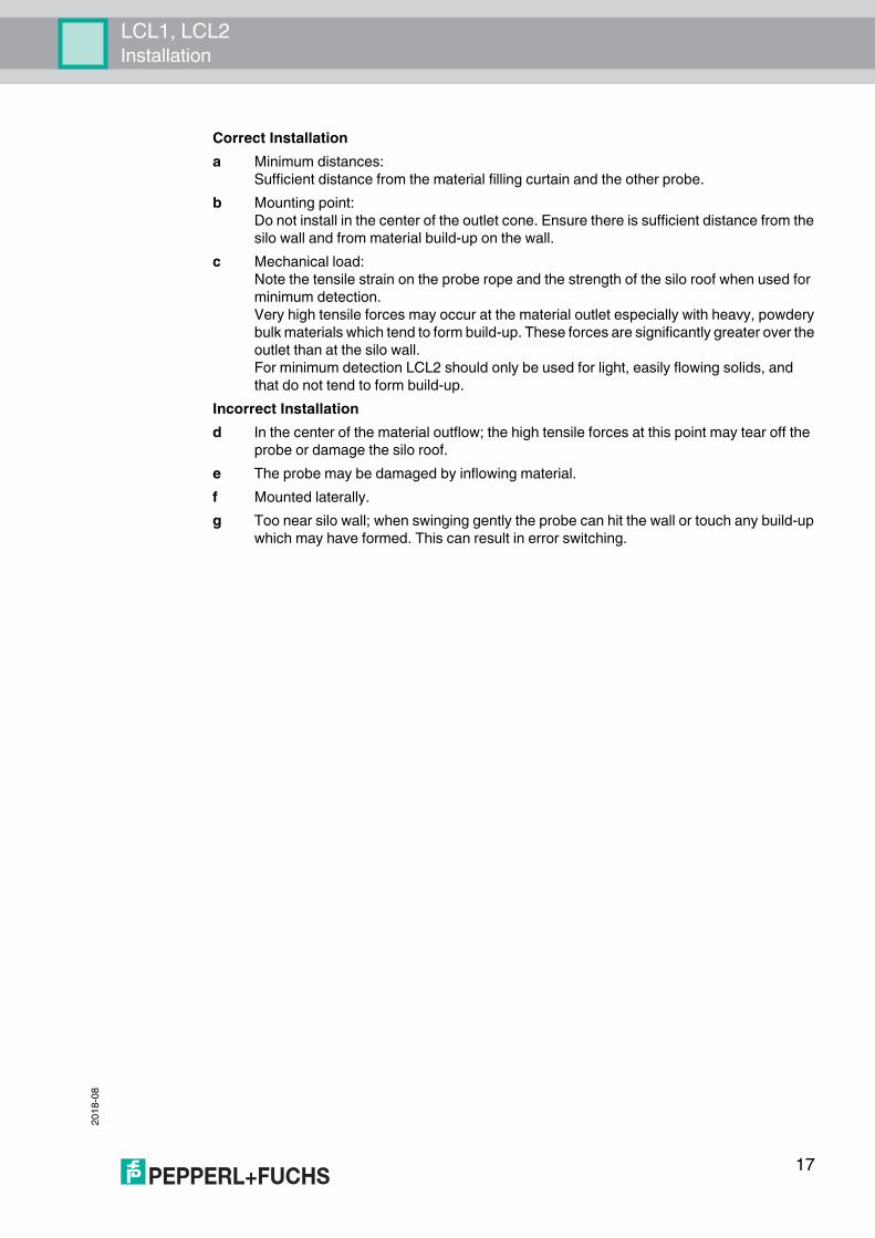
Correct Installationa Minimum distances:
Sufficient distance from the material filling curtain and the other probe.b Mounting point:
Do not install in the center of the outlet cone. Ensure there is sufficient distance from the silo wall and from material build-up on the wall.
c Mechanical load:Note the tensile strain on the probe rope and the strength of the silo roof when used for minimum detection.Very high tensile forces may occur at the material outlet especially with heavy, powderybulk materials which tend to form build-up. These forces are significantly greater over the outlet than at the silo wall.For minimum detection LCL2 should only be used for light, easily flowing solids, andthat do not tend to form build-up.
Incorrect Installationd In the center of the material outflow; the high tensile forces at this point may tear off the
probe or damage the silo roof.e The probe may be damaged by inflowing material.f Mounted laterally.g Too near silo wall; when swinging gently the probe can hit the wall or touch any build-up
which may have formed. This can result in error switching.
2018
-08
18
LCL1, LCL2Environment
7 Environment7.1 Ambient Temperature Range Tamb
• -40 to +80 °C (-40 to +176 °F)• For Dust-Ex version: -40 to +60 °C (-40 to +140 °F)
7.2 Storage Temperature-40 to +80 °C (-40 to +176 °F)
7.3 Climate ClassClimate protection acc. to EN 60068 part 2-38 (Z/AD), (IEC 68-2-38)
7.4 Degree of Protection• IP66; Type 4 encl. (with F14 housing)• IP66; Type 4x encl. (with F34 housing)
7.5 Impact ResistanceProbe with F34 housing: 7 J
7.6 Vibrational ResistanceEN 60068-2-64 (IEC 68-2-64),a(RMS) = 50 m/s2; ASD = 1.25 (m/s2)2/Hz; f = 5 to 2000 Hz, t = 3x2 h
7.7 Operating HeightUp to 2000 m (6600 foot) above mean sea level.
7.8 Electromagnetic Compatibility• Interference Emission acc. to EN 61326, Electrical Equipment Class A• Interference Immunity acc. to EN 61326, Annex A (Industrial) and NAMUR
Recommendation NE 21 (EMC)
LCL1, LCL2Process
2018
-08
19
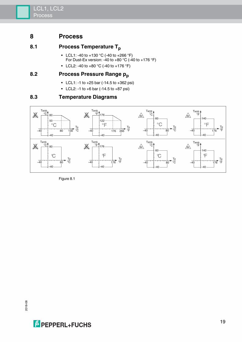
8 Process8.1 Process Temperature Tp
• LCL1: -40 to +130 °C (-40 to +266 °F)For Dust-Ex version: -40 to +80 °C (-40 to +176 °F)
• LCL2: -40 to +80 °C (-40 to +176 °F)8.2 Process Pressure Range pp
• LCL1: -1 to +25 bar (-14.5 to +362 psi)• LCL2: -1 to +6 bar (-14.5 to +87 psi)
8.3 Temperature Diagrams
Figure 8.1
80–40 130
Tamb
°C
Tp
°C
–40
80
50
–40
°C
°C
–40
60
80 –40
°F
°F
–40
140
176–40 266
°F
°F
–40
176
122
176
–40
°C
°C
–40
80
–40
°C
°C
–40
60
80 80–40
°F
°F
–40
176
176 –40
°F
°F
–40
140
176
°C
C°C°
°C°F
F°F°
°F
Tamb Tamb Tamb
Tamb Tamb Tamb Tamb
.
.
.
.
-
-
-
-
Tp Tp Tp
Tp Tp Tp Tp
2018
-08
20
LCL1, LCL2Mechanical Construction
9 Mechanical Construction
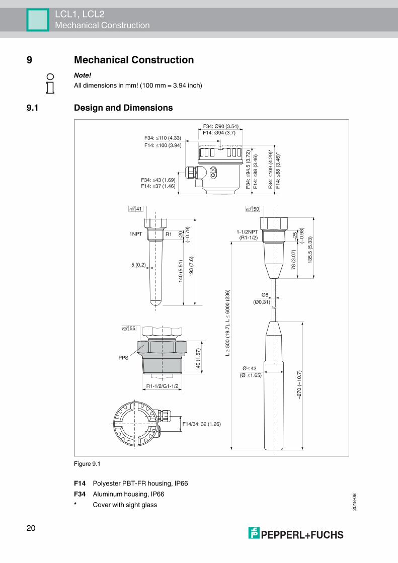
9.1 Design and Dimensions
Figure 9.1
Note!All dimensions in mm! (100 mm = 3.94 inch)
F14 Polyester PBT-FR housing, IP66F34 Aluminum housing, IP66* Cover with sight glass
41
F34: Ø90 (3.54)
F34: 110 (4.33)
1NPT
~2
0
)(~
0.7
9
14
0 (
5.5
1)
R1
~2
5
(~0
.98
)
78
(3
.07
))
( 0
72
~~
10
.7
L ,)7 .
91(
00
5L
60
00
(2
36
)
Ø8
(Ø0.31)
Ø 42
Ø( 1.65)
1-1/2NPT(R1-1/2)
PPS
40
(1
.57
)
R1-1/2/G1-1/2
5 (0.2)
F14: 100 (3.94)
F14: Ø94 (3.7)
)2
7.3(
5.4
9:
43
F
)6
4.3(
88
:4
1F
)3
3.5(
5.5
31
*)9
2.4(
90
1:
43
F
*)6
4.3(
88
:4
1F
F14/34: 32 (1.26)
F34: 43 (1.69)
F14: 37 (1.46)1
93
(7
.6)
50
55
LCL1, LCL2Mechanical Construction
2018
-08
21
9.2 Material• Probe LCL1/LCL2: PPS GF40
FDA: FCN No. 40, 21 CFR 177.1520; Regulation (EC) No 1935/2004 and No 10/2011• Probe rope LCL2: PE-HD• Probe rope seal LCL2: VMQ
FDA: 21 CFR 177.26009.3 Process Connections
Thread:• LCL1
• thread EN 10226 R1, PPS; adapter for R1-1/2 and G1-1/2, see page 27• thread ANSI NPT1, PPS; adapter for 1-1/4NPT, see page 27
• LCL2• thread EN 10226 R1-1/2, PPS• thread ANSI NPT1-1/2, PPS
9.4 Housing, Cable Entry• Housing F14: polyester PBT-FR, IP66
• Cable gland M20• Thread NPT1/2• Thread G1/2
• Housing F34: aluminium, IP66• Cable gland M20• Thread NPT1/2• Thread G1/2
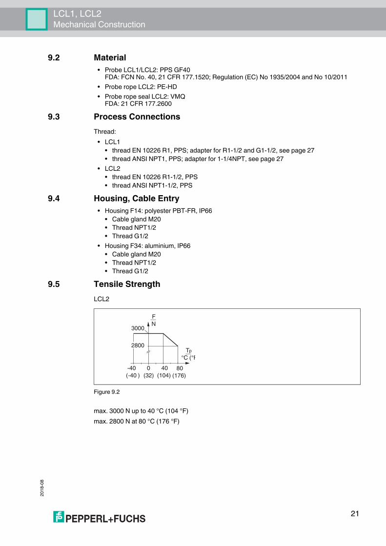
9.5 Tensile StrengthLCL2
Figure 9.2
max. 3000 N up to 40 °C (104 °F)max. 2800 N at 80 °C (176 °F)
F
N
T
°C (°F
p
3000
-40
( )-40
0
(32)
40
(104)
80
(176)
2800
2018
-08
22
LCL1, LCL2Operability
10 Operability10.1 Display Elements
• Green LED: stand-by• Red LED: switch status
10.2 Operating ElementsSwitch on electronic insert
• switching between minimum and maximum fail-safe mode• sensitivity setting (depending on dielectric constant r and buildup). It is usually not
necessary to adjust the sensitivity, see page 6.
LCL1, LCL2Certificates and Approvals
2018
-08
23
11 Certificates and Approvals
11.1 CE MarkThe device complies with the legal requirements of the EU directives.In attaching the CE Mark, Pepperl+Fuchs confirms that the device conforms to all relevant EU directives.
11.2 Ex ApprovalATEX (in conjunction with F34 aluminum housing)FM and CSA (in preparation)
Note!The following documents are also available in the download area of the Pepperl+Fuchs web site: www.pepperl-fuchs.com
2018
-08
24
LCL1, LCL2Ordering Information
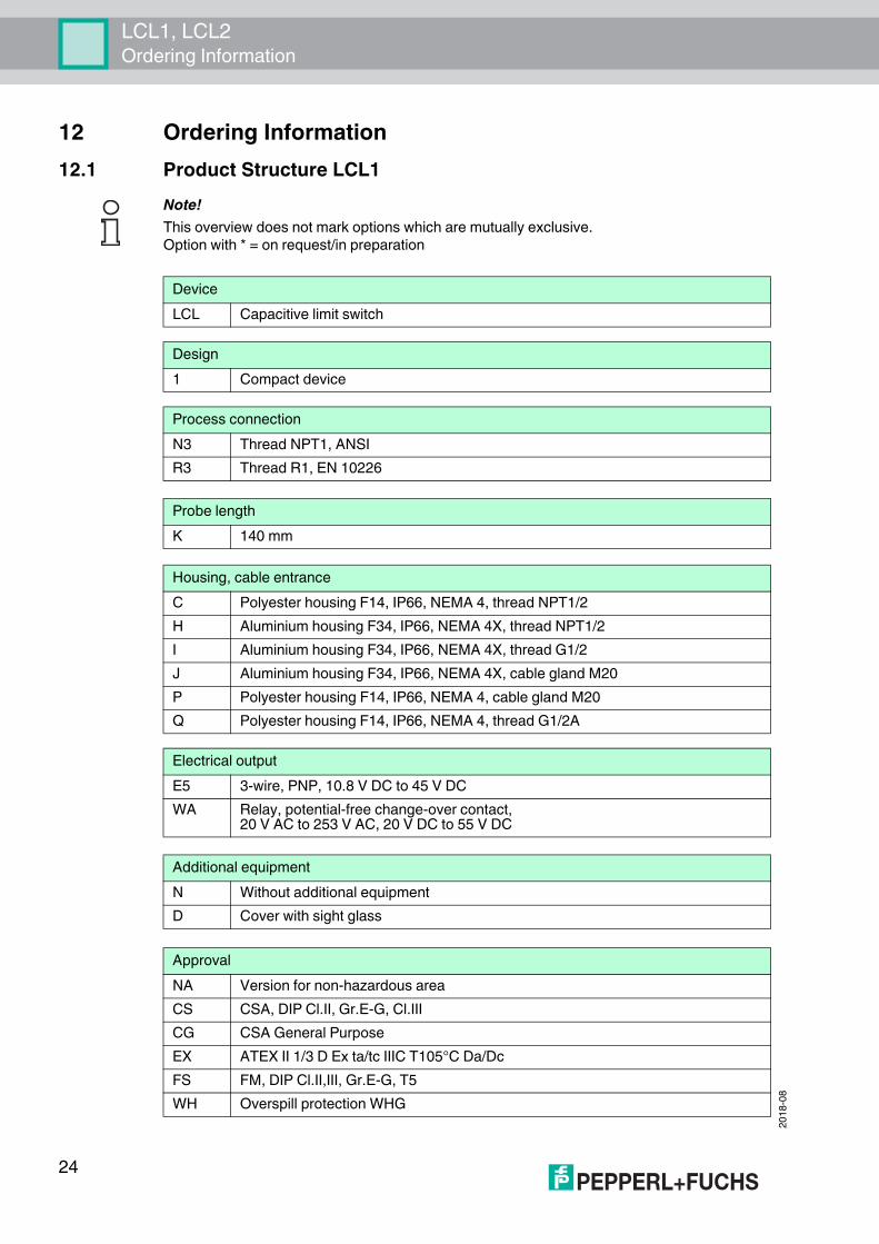
12 Ordering Information12.1 Product Structure LCL1
Note!This overview does not mark options which are mutually exclusive.Option with * = on request/in preparation
DeviceLCL Capacitive limit switch
Design1 Compact device
Process connectionN3 Thread NPT1, ANSIR3 Thread R1, EN 10226
Probe lengthK 140 mm
Housing, cable entranceC Polyester housing F14, IP66, NEMA 4, thread NPT1/2H Aluminium housing F34, IP66, NEMA 4X, thread NPT1/2I Aluminium housing F34, IP66, NEMA 4X, thread G1/2J Aluminium housing F34, IP66, NEMA 4X, cable gland M20P Polyester housing F14, IP66, NEMA 4, cable gland M20Q Polyester housing F14, IP66, NEMA 4, thread G1/2A
Electrical outputE5 3-wire, PNP, 10.8 V DC to 45 V DCWA Relay, potential-free change-over contact,
20 V AC to 253 V AC, 20 V DC to 55 V DC
Additional equipmentN Without additional equipmentD Cover with sight glass
ApprovalNA Version for non-hazardous areaCS CSA, DIP Cl.II, Gr.E-G, Cl.IIICG CSA General PurposeEX ATEX II 1/3 D Ex ta/tc IIIC T105°C Da/DcFS FM, DIP Cl.II,III, Gr.E-G, T5WH Overspill protection WHG
LCL1, LCL2Ordering Information
2018
-08
25
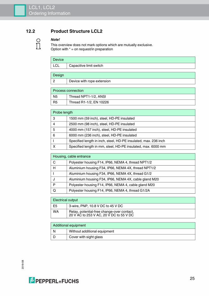
12.2 Product Structure LCL2Note!This overview does not mark options which are mutually exclusive.Option with * = on request/in preparation
DeviceLCL Capacitive limit switch
Design2 Device with rope extension
Process connectionN5 Thread NPT1-1/2, ANSIR5 Thread R1-1/2, EN 10226
Probe length3 1500 mm (59 inch), steel, HD-PE insulated4 2500 mm (98 inch), steel, HD-PE insulated5 4000 mm (157 inch), steel, HD-PE insulated6 6000 mm (236 inch), steel, HD-PE insulatedI Specified length in inch, steel, HD-PE insulated, max. 236 inchX Specified length in mm, steel, HD-PE insulated, max. 6000 mm
Housing, cable entranceC Polyester housing F14, IP66, NEMA 4, thread NPT1/2H Aluminium housing F34, IP66, NEMA 4X, thread NPT1/2I Aluminium housing F34, IP66, NEMA 4X, thread G1/2J Aluminium housing F34, IP66, NEMA 4X, cable gland M20P Polyester housing F14, IP66, NEMA 4, cable gland M20Q Polyester housing F14, IP66, NEMA 4, thread G1/2A
Electrical outputE5 3-wire, PNP, 10.8 V DC to 45 V DCWA Relay, potential-free change-over contact,
20 V AC to 253 V AC, 20 V DC to 55 V DC
Additional equipmentN Without additional equipmentD Cover with sight glass

2018
-08
26
LCL1, LCL2Ordering Information
ApprovalNA Version for non-hazardous areaCS CSA, DIP Cl.II, Gr.E-G, Cl.IIICG CSA General PurposeEX ATEX II 1/3 D Ex tc [ia Da] IIIC T108°C DcFS FM, DIP Cl.II,III, Gr.E-G, T5WH Overspill protection WHG
LCL1, LCL2Accessories
2018
-08
27
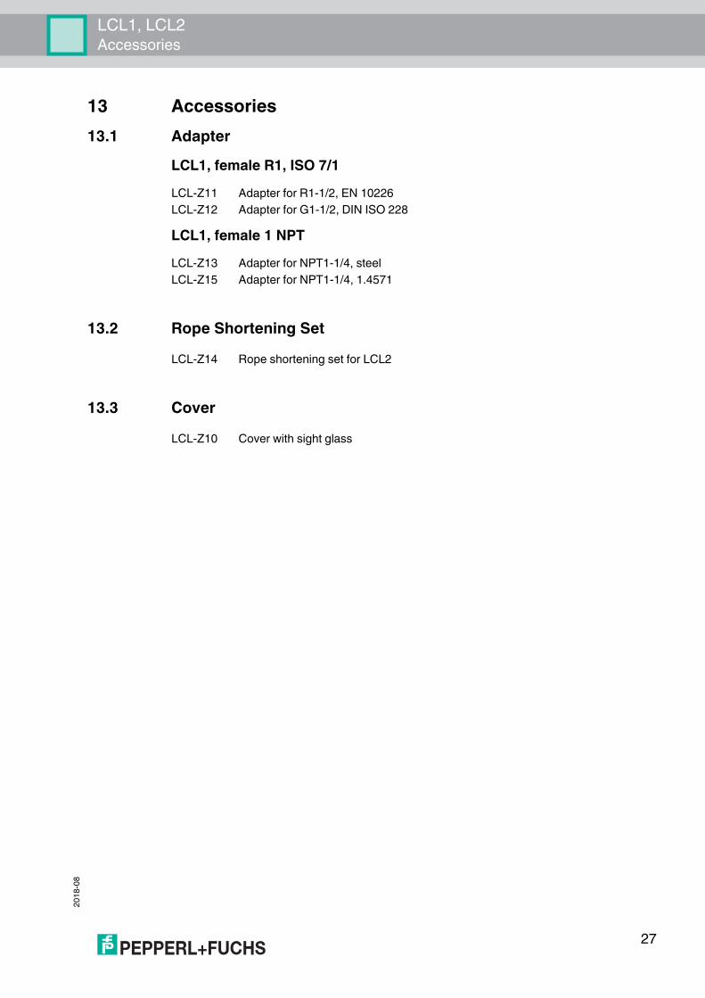
13 Accessories13.1 Adapter
LCL1, female R1, ISO 7/1
LCL1, female 1 NPT
13.2 Rope Shortening Set
13.3 Cover
LCL-Z11 Adapter for R1-1/2, EN 10226LCL-Z12 Adapter for G1-1/2, DIN ISO 228
LCL-Z13 Adapter for NPT1-1/4, steelLCL-Z15 Adapter for NPT1-1/4, 1.4571
LCL-Z14 Rope shortening set for LCL2
LCL-Z10 Cover with sight glass
2018
-08
28
LCL1, LCL2Documentation
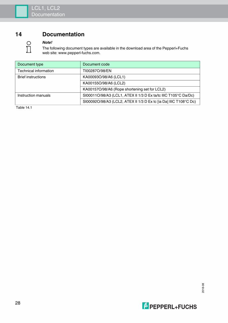
14 DocumentationNote!The following document types are available in the download area of the Pepperl+Fuchs web site: www.pepperl-fuchs.com.
Document type Document codeTechnical information TI00287O/98/ENBrief instructions KA00093O/98/A6 (LCL1)
KA00155O/98/A6 (LCL2)KA00157O/98/A6 (Rope shortening set for LCL2)
Instruction manuals SI00011O/98/A3 (LCL1, ATEX II 1/3 D Ex ta/tc IIIC T105°C Da/Dc)SI00092O/98/A3 (LCL2, ATEX II 1/3 D Ex tc [ia Da] IIIC T108°C Dc)
Table 14.1

LCL1, LCL2Notes
2018
-08
29

2018
-08
30
LCL1, LCL2Notes

LCL1, LCL2Notes
2018
-08
31

Subject to modifications Copyright PEPPERL+FUCHS • Printed in Germany
www.pepperl-fuchs.com
Worldwide HeadquartersPepperl+Fuchs GmbH68307 Mannheim · GermanyTel. +49 621 776-0E-mail: [email protected]
For the Pepperl+Fuchs representative closest to you check www.pepperl-fuchs.com/contact
PROCESS AUTOMATION –PROTECTING YOUR PROCESS
DOCT-0461C08/2018
TI00287O/98/EN/16.16