technical information ultrasonic level sensor luc-m**
TRANSCRIPT
Technical InformationTI365O/98/en/01.10185414 01/10 03
Ultrasonic Level SensorLUC-M**
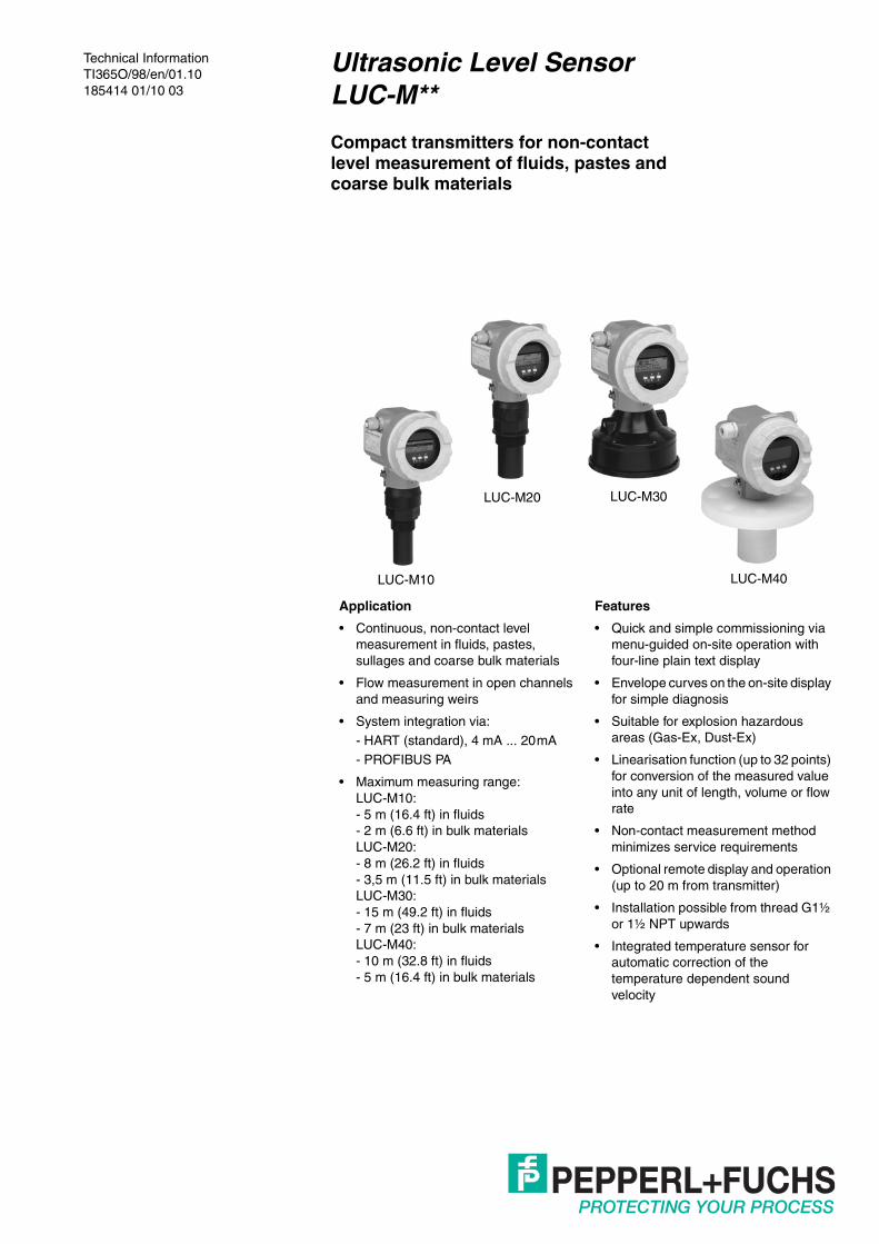
Compact transmitters for non-contactlevel measurement of fluids, pastes andcoarse bulk materials
Application
• Continuous, non-contact level measurement in fluids, pastes, sullages and coarse bulk materials
• Flow measurement in open channels and measuring weirs
• System integration via:- HART (standard), 4 mA ... 20mA- PROFIBUS PA
• Maximum measuring range:LUC-M10:- 5 m (16.4 ft) in fluids- 2 m (6.6 ft) in bulk materialsLUC-M20:- 8 m (26.2 ft) in fluids- 3,5 m (11.5 ft) in bulk materialsLUC-M30:- 15 m (49.2 ft) in fluids- 7 m (23 ft) in bulk materialsLUC-M40:- 10 m (32.8 ft) in fluids- 5 m (16.4 ft) in bulk materials
Features
• Quick and simple commissioning via menu-guided on-site operation with four-line plain text display
• Envelope curves on the on-site display for simple diagnosis
• Suitable for explosion hazardous areas (Gas-Ex, Dust-Ex)
• Linearisation function (up to 32 points) for conversion of the measured value into any unit of length, volume or flow rate
• Non-contact measurement method minimizes service requirements
• Optional remote display and operation (up to 20 m from transmitter)
• Installation possible from thread G1½ or 1½ NPT upwards
• Integrated temperature sensor for automatic correction of the temperature dependent sound velocity
LUC-M10 LUC-M40
LUC-M30LUC-M20

Ultrasonic Level Sensor LUC-M**Table of contents
DO
CT
-080
5F01
/201
018
5414
2
Function and system design. . . . . . . . . . . . . 3Measuring principle . . . . . . . . . . . . . . . . . . . . . . . . . . . . . 3Equipment architecture . . . . . . . . . . . . . . . . . . . . . . . . . . 4
Input. . . . . . . . . . . . . . . . . . . . . . . . . . . . . . . . . 5Measured variable . . . . . . . . . . . . . . . . . . . . . . . . . . . . . . 5Measuring range . . . . . . . . . . . . . . . . . . . . . . . . . . . . . . . 5
Operating frequency . . . . . . . . . . . . . . . . . . . . . . . . . . . . 6
Output . . . . . . . . . . . . . . . . . . . . . . . . . . . . . . . 6Output signal . . . . . . . . . . . . . . . . . . . . . . . . . . . . . . . . . . 6Signal on alarm . . . . . . . . . . . . . . . . . . . . . . . . . . . . . . . . 6Load HART . . . . . . . . . . . . . . . . . . . . . . . . . . . . . . . . . . . 6
Output damping . . . . . . . . . . . . . . . . . . . . . . . . . . . . . . . . 6Linearisation . . . . . . . . . . . . . . . . . . . . . . . . . . . . . . . . . . 6
Auxiliary energy . . . . . . . . . . . . . . . . . . . . . . . 7Terminal compartment . . . . . . . . . . . . . . . . . . . . . . . . . . . 7Terminal assignment . . . . . . . . . . . . . . . . . . . . . . . . . . . . 7
Fieldbus plug connector. . . . . . . . . . . . . . . . . . . . . . . . . . 8Supply voltage . . . . . . . . . . . . . . . . . . . . . . . . . . . . . . . . . 8Cable entry . . . . . . . . . . . . . . . . . . . . . . . . . . . . . . . . . . . 9
Terminals . . . . . . . . . . . . . . . . . . . . . . . . . . . . . . . . . . . . . 9Power consumption . . . . . . . . . . . . . . . . . . . . . . . . . . . . . 9Current consumption (2-wire instruments). . . . . . . . . . . . 9
HART ripple . . . . . . . . . . . . . . . . . . . . . . . . . . . . . . . . . . . 9Max. noise HART. . . . . . . . . . . . . . . . . . . . . . . . . . . . . . . 9Galvanic isolation. . . . . . . . . . . . . . . . . . . . . . . . . . . . . . . 9
Performance characteristics . . . . . . . . . . . . 10Reaction time. . . . . . . . . . . . . . . . . . . . . . . . . . . . . . . . . 10
Reference operating conditions . . . . . . . . . . . . . . . . . . . 10Measured value resolution. . . . . . . . . . . . . . . . . . . . . . . 10Pulse frequency . . . . . . . . . . . . . . . . . . . . . . . . . . . . . . . 10
Measuring error . . . . . . . . . . . . . . . . . . . . . . . . . . . . . . . 10Influence of the vapour pressure . . . . . . . . . . . . . . . . . . 10
Installation conditions . . . . . . . . . . . . . . . . . 11Installation variants LUC-M10, LUC-M20 . . . . . . . . . . . 11Installation variants LUC-M30 . . . . . . . . . . . . . . . . . . . . 11
Installation variants LUC-M40 . . . . . . . . . . . . . . . . . . . . 11Installation conditions for level measurements . . . . . . . 12Installation in narrow shafts . . . . . . . . . . . . . . . . . . . . . . 12
Installation conditions for flow measurements . . . . . . . . 13Blocking distance,nozzle installation . . . . . . . . . . . . . . . . . . . . . . . . . . . . . 14
Ambient conditions . . . . . . . . . . . . . . . . . . . 15Ambient temperature . . . . . . . . . . . . . . . . . . . . . . . . . . . 15Storage temperature . . . . . . . . . . . . . . . . . . . . . . . . . . . 15Resistance to alternatingtemperature cycles. . . . . . . . . . . . . . . . . . . . . . . . . . . . . 15Climate class . . . . . . . . . . . . . . . . . . . . . . . . . . . . . . . . . 15
Ingress protection . . . . . . . . . . . . . . . . . . . . . . . . . . . . . 15Vibration resistance . . . . . . . . . . . . . . . . . . . . . . . . . . . . 15Electromagnetic compatibility (EMC) . . . . . . . . . . . . . . . 15
Process conditions . . . . . . . . . . . . . . . . . . . 15Process temperature. . . . . . . . . . . . . . . . . . . . . . . . . . . . 15Process pressure . . . . . . . . . . . . . . . . . . . . . . . . . . . . . . 15
Mechanical construction . . . . . . . . . . . . . . . 16Design, dimensions. . . . . . . . . . . . . . . . . . . . . . . . . . . . . 16Weight. . . . . . . . . . . . . . . . . . . . . . . . . . . . . . . . . . . . . . . 18
Housing design . . . . . . . . . . . . . . . . . . . . . . . . . . . . . . . . 19Process connection, sealing material, sensor material. . 19
Human interface . . . . . . . . . . . . . . . . . . . . . . 20Display and operating elements . . . . . . . . . . . . . . . . . . . 20On-site operation . . . . . . . . . . . . . . . . . . . . . . . . . . . . . . 21
Remote control . . . . . . . . . . . . . . . . . . . . . . . . . . . . . . . . 22
Certificates and approvals. . . . . . . . . . . . . . 22CE mark . . . . . . . . . . . . . . . . . . . . . . . . . . . . . . . . . . . . . 22Ex approval . . . . . . . . . . . . . . . . . . . . . . . . . . . . . . . . . . . 22External standards and guidelines . . . . . . . . . . . . . . . . . 22
Ordering information . . . . . . . . . . . . . . . . . . 23Product structure LUC-M10 . . . . . . . . . . . . . . . . . . . . . . 23
Product structure LUC-M20 . . . . . . . . . . . . . . . . . . . . . . 23Product structure LUC-M30 . . . . . . . . . . . . . . . . . . . . . . 24Product structure LUC-M40 . . . . . . . . . . . . . . . . . . . . . . 24
Scope of delivery . . . . . . . . . . . . . . . . . . . . . . . . . . . . . . 25
Accessories . . . . . . . . . . . . . . . . . . . . . . . . . 25Weather protection cover . . . . . . . . . . . . . . . . . . . . . . . . 25Mounting bracket for LUC-M10/LUC-M20 . . . . . . . . . . . 25Mounting bracket for LUC-M30/LUC-M40 . . . . . . . . . . . 25
Cantilever . . . . . . . . . . . . . . . . . . . . . . . . . . . . . . . . . . . . 26Mounting frame. . . . . . . . . . . . . . . . . . . . . . . . . . . . . . . . 26Wall bracket . . . . . . . . . . . . . . . . . . . . . . . . . . . . . . . . . . 27
Adapter flange for LUC-M10/LUC-M20. . . . . . . . . . . . . . 27Universal slip-on flange for LUC-M30. . . . . . . . . . . . . . . 28Remote display . . . . . . . . . . . . . . . . . . . . . . . . . . . . . . . . 28
Display and operating module LUC-Z15. . . . . . . . . . . . . 29Service adapter. . . . . . . . . . . . . . . . . . . . . . . . . . . . . . . . 29Profiboard . . . . . . . . . . . . . . . . . . . . . . . . . . . . . . . . . . . . 29
Proficard . . . . . . . . . . . . . . . . . . . . . . . . . . . . . . . . . . . . . 29
Supplementary documentation. . . . . . . . . . 30Operating manual . . . . . . . . . . . . . . . . . . . . . . . . . . . . . . 30Description of device functions . . . . . . . . . . . . . . . . . . . . 30Short instructions . . . . . . . . . . . . . . . . . . . . . . . . . . . . . . 30
Safety Instructions . . . . . . . . . . . . . . . . . . . . . . . . . . . . . 31Control drawings/installation drawings . . . . . . . . . . . . . . 32

Ultrasonic Level Sensor LUC-M**Function and system design
DO
CT
-080
5F01
/201
018
5414
3
Function and system design
Measuring principle
E: empty distance; F: span (full distance); D: distance from sensor membrane - product surface; L: level; BD: blocking distance
Time-of-flight methodThe sensor of the LUC-M** transmits ultrasonic pulses in the direction of the product surface. There, they are reflected back and received by the sensor. The LUC-M** measures the time t between pulse transmission and reception. The instrument uses the time t (and the velocity of sound c) to calculate the distance D between the sensor membrane and the product surface:
D = c x t/2
As the device knows the empty distance E from a user entry, it can calculate the level as follows:
L = E – D
An integrated temperature sensor compensates for changes in the velocity of sound caused by temperature changes.
Interference echo suppressionThe interference echo suppression feature on the LUC-M** ensures that interference echoes (e. g. from edges, welded joints and installations) are not interpreted as a level echo.
CalibrationEnter the empty distance E and the span F to calibrate the device.
Blocking distanceSpan F may not extend into the blocking distance BD. Level echoes from the blocking distance cannot be evaluated due to the transient characteristics of the sensor.
Sensor BD Max. range fluids Max. range bulk materials
LUC-M10 0.25 m (9.8 in) 5 m (16.4 ft) 2 m (6.6 ft)
LUC-M20 0.35 m (13.8 in) 8 m (26.2 ft) 3.5 m (11.5 ft)
LUC-M30 0.6 m (23.6 in) 15 m (49.2 ft) 7 m (23 ft)
LUC-M40 0.4 m (15.7 in) 10 m (32.8 ft) 5 m (16.4 ft)
20 mA100 %
4 mA0 %
D
L
FE
BD

Ultrasonic Level Sensor LUC-M**Function and system design
DO
CT
-080
5F01
/201
018
5414
4
Equipment architecture 4 mA … 20 mA output with HART protocolThe complete measuring system consists of:
If the HART communication resistor is not built into the supply unit, it is necessary to insert a communication resistor of 250 Ω into the 2-wire line.
On-site operation• with display and operating module LUC-Z15• with a Personal Computer, a modem and the operating software PACTwareTM
Remote operation• with HART handheld terminal• with a Personal Computer, a HART modem and the operating software PACTwareTM
System integration using PROFIBUS PAA maximum of 32 transmitters (8 if mounted in an explosion hazardous location EEx ia IIC according to FISCO-model) can be connected to the bus.The segment coupler provides the operating voltage to the bus. Both on-site as well as remote operation are possible.For detailed information on the PROFIBUS PA standard refer to the standards EN 50170/DIN 19245 (PROFIBUS PA) and EN 50020 (FISCO model).
E+–
%
1# % &
Copy
G H I
P Q R S
, ( ) ‘
A B C
Paste
PageOn
PageUp
DeleteBksp
Insert
J K L
T U V
_ < >
D E F
Hot Key
+ Hot Key
M N O
W X Y Z
+ * /
4
7
.
2
5
8
0
375FIELD COMMUNICATOR
3
6
9
-
9 6
DELTABAR: * * * * * * * *ONLINE
1 QUICK SETUP2 OPERATING MENU
4 SV 0 °C3 PV 352 mbar
HELP SAVE
dsdmdmdf das.asdas fa
asas la.
PACTwareTM
PACTwareTM
HART communicator
Transmitter powersupplye. g. P+F(communicationresistor included)
PLC
HART modem
Operating anddisplay moduleLUC-Z15
Power supply(for 4-wire)
Modem
I II
Modem
BARCON
LUC-M**Pulscon LTC
E+–
%
PACTwareTM
TPROFIBUS PA
PROFIBUS DP
PC with PACTwareTM
and Profiboardor Proficard
additional functions(valves etc.)
Segment coupler
Display and control moduleLUC-Z15
PLC

Ultrasonic Level Sensor LUC-M**Input
DO
CT
-080
5F01
/201
018
5414
5
Input
Measured variable The distance D between the sensor membrane and the product surface is measured.
Using the linearisation function, the device uses D to calculate:• level L in any units• volume V in any units• flow Q across measuring weirs or open channels in any units
Measuring range The measuring range is limited by the range of a sensor. The sensor range is, in turn, dependent on the operating conditions. To estimate the actual range, proceed as follows (see also the calculation example):1. Determine which of the influences shown in the following table are appropriate for your process.2. Add the corresponding attenuation values.3. From the total attenuation, use the diagram to calculate the range.
Fluid surface Attenuation
calm 0 dB
waves 5 dB ... 10 dB
strong turbulence (e. g. stirrers) 10 dB ... 20 dB
foaming ask Pepperl+Fuchs
Bulk material surface Attenuation
hard, rough (e. g. rubble) 40 dB
soft (e. g. peat, dust-covered clinker) 40 dB ... 60 dB
Dust Attenuation
no dust formation 0 dB
little dust formation 5 dB
heavy dust formation 5 dB ... 20 dB
Filling curtain in detection range Attenuation
none 0 dB
small quantities 5 dB ... 10 dB
large quantities 10 dB ... 40 dB
Temperature difference between sensor and product surface Attenuation
to 20 °C (293 K) 0 dB
to 40 °C (313 K) 5 dB ... 10 dB
to 80 °C (353 K) 10 dB ... 20 dB
LUC-M30
LUC-M40
LUC-M20
LUC-M10
10 20 30 40 50 60 70 80
1
2
3
4
5
6
7
8
9
10
11
12
13
14
15
Attenuation in dB
Ran
ge in
m

Ultrasonic Level Sensor LUC-M**Output
DO
CT
-080
5F01
/201
018
5414
6
Example (for LUC-M30)For typical solid applications, a certain amount of dust coverage is normally present. Therefore, the following range results from the table and the diagram.
These measuring conditions have been taken into account during the calculation of the maximum measuring range in solid applications.
Operating frequency
Output
Output signal according to the instrument version ordered:
• 4 mA … 20 mA with HART protocol• PROFIBUS PA
Signal on alarm Error information can be accessed via the following interfaces:• on-site display (error symbol, error code and plain text description)• current output (configurable)• digital interface
Load HART Minimum load for HART communication: 250 Ω
Output damping freely selectable, 0 s ... 255 s
Linearisation The linearisation function of the LUC-M** allows conversion of the measured value into any unit of length or volume. In open channels or measuring weirs, also a flow linearisation is possible (calculation of the flow from the measured level). The linearisation table for calculating the volume in an horizontal cylindrical tank is preprogrammed. You can also enter any number of other tables containing up to 32 value pairs either manually or semi-automatically (by filling the vessel under controlled conditions).
• Dust-covered rubble approx. 50 dB• No dust development 0 dB• No filling curtain in
detection range0 dB
• Temperature difference < 20 K 0 dBapprox. 50 dB range approx. 7 m (23 ft)
Sensor Operating frequency
LUC-M10 approx. 70 kHz
LUC-M20 approx. 50 kHz
LUC-M30 approx. 35 kHz
LUC-M40 approx. 42 kHz

Ultrasonic Level Sensor LUC-M**Auxiliary energy
DO
CT
-080
5F01
/201
018
5414
7
Auxiliary energy
Terminal compartment In the F12 housing, the terminals are located underneath the housing cover. In the T12 housing, they are under the cover of the separate terminal compartment.
Terminal assignment
• Connect the connecting line to the screw terminals (line cross-sections of 0.5 mm ... 2.5mm (0.02 in ... 0.1 in)) in the terminal compartment.
• Use 2-wire twisted pair cable with screen for the connection.• Protective circuitry against reverse polarity, RFI and over-voltage peaks is built into the device.
sealed terminal compartment
F12 housing T12 housing
4 mA ... 20 mA with HART, 2-wire 4 mA ... 20 mA with HART, active, 4-wire
(> 250 Ω)
3I+ I-
1 2L+L-
4 mA ... 20 mA
PAL4
Communicationresistor
HARTmodem
alternative
Auxiliary voltage
Test socket fortesting of thesignal current
5I+ I-
1 2N/L-L1/L+
AC / DC
4 mA ... 20 mA
PAL
DC
6
(> 250 Ω)
HARTmodem
alternative
Auxiliary voltage
Communicationresistor
Display unit,Recorder, PCS

Ultrasonic Level Sensor LUC-M**Auxiliary energy
DO
CT
-080
5F01
/201
018
5414
8
The digital communication signal is transmitted to the bus via a 2-wire connection. The bus also provides the auxiliary energy. Please use 2-wire twisted pair cable with screen.
Fieldbus plug connector For the versions with fieldbus plug connector, the signal line can be connected without opening the housing.
Pin assignment of the M12 plug connector (PROFIBUS PA plug)
Supply voltage HART, 2-wireThe following values are the voltages across the terminals directly at the instrument:
1) Start-up current 11 mA
HART, 4-wire
PROFIBUS PA
3 41 2– +
T-Box
PAL
PROFIBUS PA
Pin Meaning
1 Ground
2 Signal +
3 Signal -
4 not connected
1 3
2 4
Version Currentconsumption
Terminal voltageminimum
Terminal voltagemaximum
2-wire HART
standard 4 mA 14 V 36 V
20 mA 8 V 36 V
EEx ia 4 mA 14 V 30 V
20 mA 8 V 30 V
EEx d 4 mA 14 V 30 V
20 mA 11 V 30 V
fixed current, adjustable, e. g. for solar power operation(measured value via HART)
standard11 mA 10 V 36 V
EEx ia11 mA 10 V 30 V
fixed current for HART multidrop mode
standard 4 mA1) 14 V 36 V
EEx ia 4 mA1) 14 V 30 V
Version Voltage Max. load
DC 10.5 V ... 32 V 600 ΩAC 50/60 Hz 90 V ... 253 V 600 Ω

Ultrasonic Level Sensor LUC-M**Auxiliary energy
DO
CT
-080
5F01
/201
018
5414
9
Cable entry • cable gland: M20 x 1.5 (recommended cable diameter 6 mm ... 10 mm (0.24 in ... 0.4 in))• cable entry G½ or ½ NPT• PROFIBUS PA M12 plug
Terminals Cable cross section 0.5 mm2 ... 2.5 mm2 (20 AWG ... 14 AWG)
Power consumption
Current consumption(2-wire instruments)
HART ripple 47 Hz ...125 Hz: Upp = 200 mV (measured at 500 Ω)
Max. noise HART 500 Hz ...10 kHz: Urms = 2.2 mV (measured at 500 Ω)
Galvanic isolation With 4-wire devices, the evaluation electronics and mains voltage are galvanically isolated from each other.
Version Power consumption
2-wire 51 mW ... 800 mW
4-wire AC max. 4 VA
4-wire DC; LUC-M10/LUC-M20 330 mW ... 830 mW
4-wire DC; LUC-M30/LUC-M40 600 mW ... 1 W
Communication Current consumption
HART 3.6 mA ... 22 mA
PROFIBUS PA max. 13 mA

Ultrasonic Level Sensor LUC-M**Performance characteristics
DO
CT
-080
5F01
/201
018
5414
10
Performance characteristics
Reaction time The reaction time depends on the parameter settings. The minimum values are:
• 2-wire devices (LUC-M10, LUC-M20, LUC-M40): min. 2 s• 2-wire devices (LUC-M30 – PROFIBUS PA): min. 2 s• 4-wire devices (LUC-M10, LUC-M20, LUC-M30, LUC-M40): min. 0.5 s
Reference operating conditions
• temperature = +20 °C (293 K)• pressure = 1013 mbar abs.• humidity = 50 %• ideal reflective surface (e. g. calm, smooth fluid surface)• no interference reflections within signal beam• set application parameters:
– tank shape = flat ceiling– medium property = liquid– process conditions = calm surface
Measured value resolution
Pulse frequency • 2-wire devices (LUC-M10, LUC-M20, LUC-M40): max. 0.5 Hz • 2-wire devices (LUC-M30 – PROFIBUS PA): max. 0.5 Hz • 4-wire devices (LUC-M10, LUC-M20, LUC-M30, LUC-M40): max. 2 HzThe exact values are dependent on the type of device and the parameter settings.
Measuring error Typical specifications for reference operating conditions (include linearity, repeatability, and hysteresis):
1) whichever is greater
Influence of the vapour pressure
The vapor pressure at 20 °C (293 K) gives a hint on the accuracy of the ultrasonic level measurement. If the vapor pressure at 20 °C (293 K) is below 50 mbar, ultrasonic level measurement is possible with a very high accuracy. This is valid for water, aqueous solutions, water-solid-solutions, dilute acids (hydrochloric acid, sulfuric acid, ...), dilute bases (caustic soda, ...), oils, greases, slurries, pastes, ...High vapor pressures or outgassing media (ethanol, acetone, ammonia, ...) can influence the accuracy. If conditions like these are present, please contact the Pepperl+Fuchs support.
Sensor Measured value resolution
LUC-M10 1 mm (0.04 in)
LUC-M20 1 mm (0.04 in)
LUC-M30 2 mm (0.08 in)
LUC-M40 2 mm (0.08 in)
Sensor Measuring error
LUC-M10 ± 2 mm (0.08 in) or 0.2% of set measuring range (empty calibration)1)
LUC-M20 ± 2 mm (0.08 in) or 0.2% of set measuring range (empty calibration)1)
LUC-M30 ± 4 mm (0.16 in) or 0.2% of set measuring range (empty calibration)1)
LUC-M40 ± 4 mm (0.16 in) or 0.2% of set measuring range (empty calibration)1)
Ultrasonic Level Sensor LUC-M**Installation conditions
DO
CT
-080
5F01
/201
018
5414
11
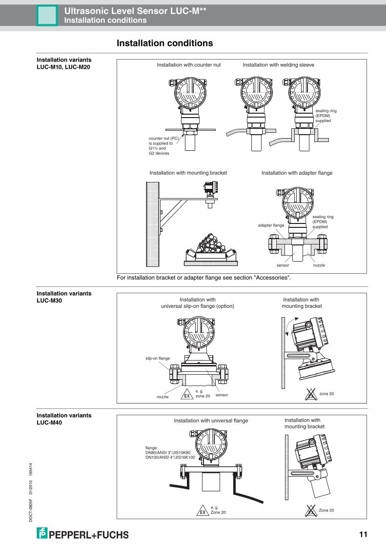
Installation conditions
Installation variantsLUC-M10, LUC-M20
For installation bracket or adapter flange see section "Accessories".
Installation variants LUC-M30
Installation variantsLUC-M40
Installation with welding sleeveInstallation with counter nut
Installation with mounting bracket
counter nut (PC) is supplied toG1½ andG2 devices
adapter flange
sensor nozzle
sealing ring(EPDM)supplied
Installation with adapter flange
sealing ring(EPDM)supplied
.-
Installation with mounting bracket
Installation withuniversal slip-on flange (option)
slip-on flange
sensornozzlee. g.zone 20 zone 20
Installation with mounting bracket
Installation with universal flange
flange:DN80/ANSI 3"/JIS10K80DN100/ANSI 4"/JIS16K100
.-e. g.Zone 20 Zone 20

Ultrasonic Level Sensor LUC-M**Installation conditions
DO
CT
-080
5F01
/201
018
5414
12
Installation conditions for level measurements
• Do not install the sensor in the middle of the tank (3). We recommend leaving a distance between the sensor and the tank wall (1) measuring 1/6 of the tank diameter.
• Use a protective cover, in order to protect the device from direct sun or rain (2).• Avoid measurements through the filling curtain (4).• Make sure that equipment (5) such as limit switches, temperature sensors, etc. are not located
within the emitting angle α. In particular, symmetrical equipment (6) such as heating coils, baffles etc. can influence measurement.
• Align the sensor so that it is vertical to the product surface (7).• Never install two ultrasonic measuring devices in a tank, as the two signals may affect each
other.• To estimate the detection range, use the 3 dB emitting angle α:
Installation in narrow shafts
Sensor α Lmax rmax
LUC-M10 11° 5 m (16.4 ft) 0.48 m (18.9 in)
LUC-M20 11° 8 m (26.2 ft) 0.77 m (30.3 in)
LUC-M30 6° 15 m (49.2 ft) 0.79 m (31.1 in)
LUC-M40 9° 10 m (32.8 ft) 0.96 m (37.8 in)
1
2 3 4
5
6
1/6D
7
D
r
α L
In narrow shafts with strong interference echoes, we recommend using an ultrasound guide pipe (e. g. PE or PVC wastewater pipe) with a minimum diameter of 100 mm (3.9 in).Make sure that the pipe is not soiled by accumulated dirt. If necessary, clean the pipe at regular intervals.
ENDRESS+HA USERProsonic M
ENDRESS+HA USERProsonic M
ventinghole

Ultrasonic Level Sensor LUC-M**Installation conditions
DO
CT
-080
5F01
/201
018
5414
13
Installation conditions for flow measurements
• Install the LUC-M** at the inflow side, as close above the maximum water level Hmax as possible (take into account the blocking distance BD).
• Position the LUC-M** in the middle of the channel or weir.• Align the sensor membrane parallel to the water surface.• Keep to the installation distance of the channel or weir.• You can enter the "Flow to Level" linearisation curve ("Q/h curve") using via the on-site display.
Example: Khafagi-Venturi flume
Example: Triangular weir
1 x b0
b0
BD
Hmax
Khafagi - Venturi - flume direction of flow
inflow outflow
empt
y ca
libr.
max
max
max
max
min. 3 H
H
min. 2 H
α
min. 2 H
BD
(= full calibr.)
empt
y ca
libr.

Ultrasonic Level Sensor LUC-M**Installation conditions
DO
CT
-080
5F01
/201
018
5414
14
Blocking distance,nozzle installation
Install the LUC-M** at a height so that the blocking distance BD is not undershot, even at maximum fill level. Use a pipe nozzle if you cannot maintain the blocking distance in any other way. The interior of the nozzle must be smooth and may not contain any edges or welded joints. In particular, there should be no burr on the inside of the tank side nozzle end. Note the specified limits for nozzle diameter and length. To minimise disturbing factors, we recommend an angled socket edge (ideally 45°).
BD: blocking distance; SD: safety distance; E: empty calibration; F: full calibration (span); D: nozzle diameter; L: nozzle length
" Caution!If the blocking distance is undershot, it may cause device malfunction.
!Note! In order to prevent the level from entering the blocking distance, you can specify a safety distance (SD). If the level is within this safety distance, the LUC-M** outputs a warning or alarm message.
Maximum nozzle length L
Nozzle diameter D LUC-M10 LUC-M20 LUC-M30 LUC-M40
DN50/2" 80 mm
DN80/3" 240 mm 240 mm 250 mm
DN100/4" 300 mm 300 mm 300 mm 300 mm
DN150/6" 400 mm 400 mm 300 mm 400 mm
DN200/8" 400 mm 400 mm 300 mm 400 mm
DN250/10" 400 mm 400 mm 300 mm 400 mm
DN300/12" 400 mm 400 mm 300 mm 400 mm
Emitting angle α 11° 11° 6° 9°
Blocking distance 0.25 m 0.35 m 0.6 m 0.4 m
Max. range in liquids 5 m 8 m 15 m 10 m
Max. range in solids 2 m 3,5 m 7 m 5 m
FE
BDSD
LD
LUC-M10/20
L
D
LUC-M30
L
D
LUC-M40

Ultrasonic Level Sensor LUC-M**Ambient conditions
DO
CT
-080
5F01
/201
018
5414
15
Ambient conditions
Ambient temperature -40 °C ... +80 °C (233 K ... 353 K)
The functionality of the LC display becomes restricted at Tu < -20 °C (253 K) and Tu > +60 °C (333 K).
If the device is operated outdoors in strong sunlight, you should use a protective cover.
Storage temperature -40 °C ... +80 °C (233 K ... 353 K)
Resistance to alternatingtemperature cycles
to EN 60068-2-14; Nb test: +80 °C/-40 °C (353 K/233 K), 1 K/min, 100 cycles
Climate class EN 60068-2-38 (test Z/AD) DIN/IEC 68 T2-30Db
Ingress protection • with closed housing, tested according to– IP68, NEMA 6P (24h at 1.83m under water surface)– IP66, NEMA 4x
• with open housing: IP20, NEMA 1 (also ingress protection of the display)
"Caution!Degree of protection IP68 NEMA 6P applies for M12 PROFIBUS PA plugs only when the PROFIBUS cable is plugged in.
Vibration resistance EN 60068-2-64/IEC 68-2-64: 20 Hz ... 2000 Hz, 1 ((m/s2)2/Hz; 3 x 100 min
Electromagnetic compatibility (EMC)
• interference emission to EN 61326, Equipment Class B.• interference immunity to EN 61326, appendix A (industrial) and NAMUR recommendation
NE 21 (EMC).• a standard installation cable is sufficient if only the analogue signal is used. Use a screened
cable when working with a superimposed communication signal (HART).
Process conditions
Process temperature -40°C ... +80°C (233 K ... 353 K)A temperature sensor is integrated in the sensor for correction for the temperature-dependent time-of-flight.
Process pressure • LUC-M10/LUC-M20: 0.7 bar ... 3 bar abs.• LUC-M30/LUC-M40: 0.7 bar ... 2.5 bar abs.
Ultrasonic Level Sensor LUC-M**Mechanical construction
DO
CT
-080
5F01
/201
018
5414
16
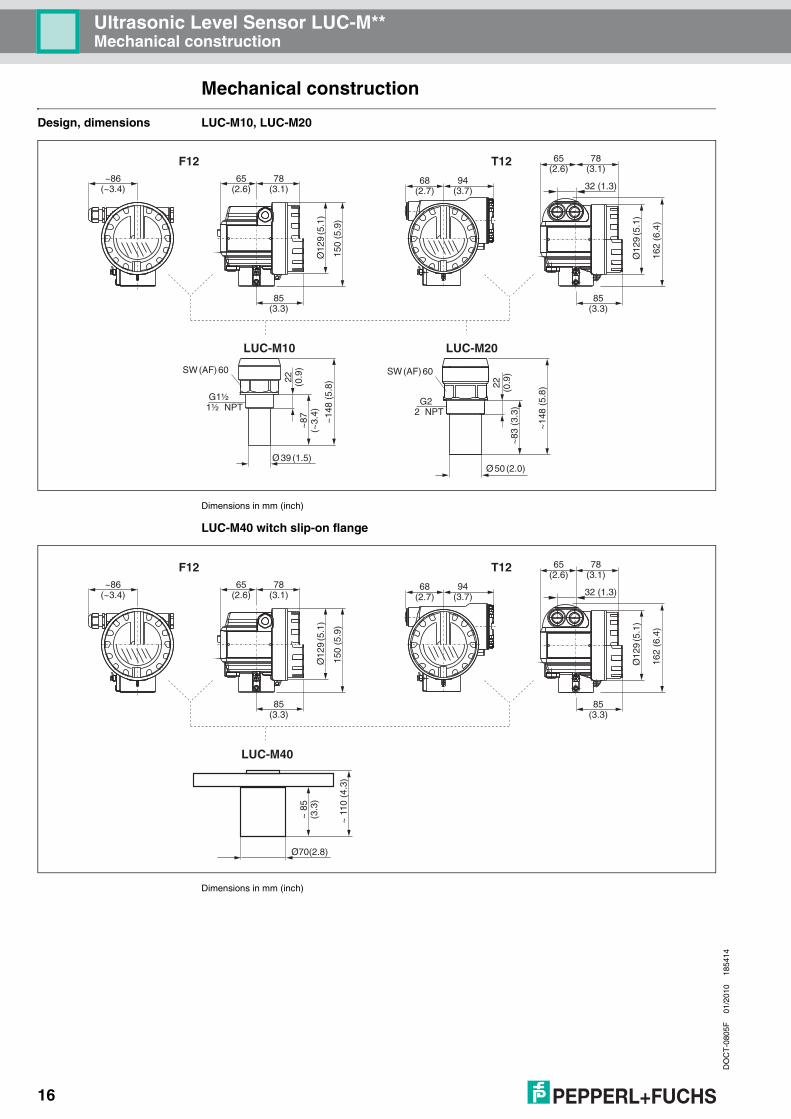
Mechanical construction
Design, dimensions LUC-M10, LUC-M20
Dimensions in mm (inch)
LUC-M40 witch slip-on flange
Dimensions in mm (inch)
65(2.6)
78(3.1)
Ø12
9(5
.1)
~~
86( 3.4)
78(3.1)
85(3.3)
85(3.3)
65(2.6)
Ø12
9(5
.1)
162
(6.4
)
150
(5.9
)
68(2.7)
94(3.7)
~14
8(5
.8)
~83
(3.3
)
22 (0.9
)
LUC-M10 LUC-M20
Ø39(1.5)Ø50 (2.0)
~14
8(5
.8)
~87
(3.
4)~
22 (0.9
)
32 (1.3)
F12 T12
SW(AF)60
G22 NPT
SW(AF)60
G1½1½ NPT
~11
0(4
.3)
Ø70(2.8)
~85
(3.3
)
LUC-M40
65(2.6)
78(3.1)
Ø12
9(5
.1)
~~
86( 3.4)
78(3.1)
85(3.3)
85(3.3)
65(2.6)
Ø12
9(5
.1)
162
(6.4
)
150
(5.9
)
68(2.7)
94(3.7) 32 (1.3)
F12 T12

Ultrasonic Level Sensor LUC-M**Mechanical construction
DO
CT
-080
5F01
/201
018
5414
17
LUC-M40 with mounting bracket
Dimensions in mm (inch)
LUC-M30
Dimensions in mm (inch)A: with slip-on flange, B: with mounting bracket
Mounting bracket for LUC-M30 and LUC-M40
Dimensions in mm (inch)
F12/T12
75(3.0) 119 (4.7)
M8
105
(4.1
)
LUC-M40
30(1
.2)
85 (3.3)
2 x M8
65(2.6)
78(3.1)
Ø12
9(5
.1)
~86(3.4)
150
(5.9
)
~24
8(9
.8)
158 (6.2)Ø230 (9.1)
F12
75 (3.0)
89 (3.5)
A
ANSI 4'' DN 100 *
B
11 (0.43)
119 (4.68)
2 (0.079)
25(0.98)
120
(4.7
)
~12
3(4
.8)
25(0.98)
40 (1.6) 40 (1.6)

Ultrasonic Level Sensor LUC-M**Mechanical construction
DO
CT
-080
5F01
/201
018
5414
18
Flanges for LUC-M40
Dimensions in mm (inch)
Weight
Suitable for A B C D E Number of boreholes
3" 150lbs/DN80 PN16/10K 80 150 mm(5.91")
160 mm(6.30")
200 mm(7.87")
19 mm(0.75")
45° 8
4" 150 lbs/DN100 PN16/10K 100 175 mm(6.90")
190,5 mm(7.50")
228,6 mm(9.00")
19 mm(0.75")
45° 8
6" 150 lbs/DN150 PN16/10 K 150 240 mm(9.45")
241,3 mm(9.50")
285 mm(11.22")
23 mm(0.91")
45° 8
8" 150 lbs 298,5 mm(11.75")
298,5 mm(11.75")
342,9 mm(13.50")
22,5 mm(0.89")
45° 8
DN200 PN16/10 K 200 290 mm(11.42")
295 mm(11.61")
340 mm(13.39")
23 mm(0.91")
30° 12
G2ISO228
20(0
.79)
C
E
A
B
D
Sensor Weight
LUC-M10 approx. 2.5 kg
LUC-M20 approx. 2.6 kg
LUC-M30 approx. 3.5 kg
LUC-M40 approx. 3 kg

Ultrasonic Level Sensor LUC-M**Mechanical construction
DO
CT
-080
5F01
/201
018
5414
19
Housing design Types of housings• F12 housing with sealed terminal compartment for standard or EEx ia applications• T12 housing with separate terminal compartment and explosion proof encapsulation
MaterialAluminium, seawater resistant, chromed, powder-coated
Cover• Aluminium, for version without on-site display.• Inspection glass for version with on-site display. This version cannot be supplied together with
the ATEX II 1/2 D certificate.
Process connection,sealing material,sensor material
1) Pepperl+Fuchs supplies DIN/EN flanges made of stainless steel AISI 316L with the material number 1.4435 or 1.4404. With regard to their temperature stability properties, the materials 1.4435 and 1.4404 are grouped under 13E0 in EN 1092-1, table 18. The chemical composition of the two materials can be identical.
Sensor Process connection Material in contact with process
LUC-M10 • thread G1½• thread 1½ NPT - 11.5
sensor: PVDFseal: EPDM
LUC-M20 • thread G2• thread 2 NPT - 11.5
sensor: PVDFseal: EPDM
LUC-M30 • universal flangeDN 100/ANSI 4"/JIS 16K100
• mounting bracket
sensor: UP and stainless steel 1.4571 (316Ti)seal: EPDMflange: PP or stainless steel 1.4571 (316Ti)
LUC-M40 • universal flangeDN 80/ANSI 3"/JIS 10K 80
• universal flangeDN 100/ANSI 4"/JIS 16K100
• mounting bracket
sensor: PVDFseal: Viton or EPDMflange: PP, PVDF or stainless steel 1.4535 or 1.4404 (316L)1

Ultrasonic Level Sensor LUC-M**Human interface
DO
CT
-080
5F01
/201
018
5414
20
Human interface
Display and operating elements
The LCD module LUC-Z15 for display and operation is located beneath the housing cover. The measured value is legible through the glass in the cover. Open the cover to operate the device.
Function of the keys
Symbol in display
continous flashing
Meaning Alarm Warning Communication Security locking
Key(s) Meaning
O or VNavigate upwards in the selection list.Edit numeric value within a function.
S or VNavigate downwards in the selection list.Edit numeric value within a function.
X or ZNavigate to the left within a function group.
FNavigate to the right within a function group, confirmation.
O and For
S and F
Contrast settings of the LCD.
O and S and F
Hardware lock/unlockAfter a hardware lock, an operation of the instrument via display orcommunication is not possible!The hardware can only be unlocked via the display. An unlock parameter must be entered to do so.
ENDRESS+HA USER
MICR OPILOT II
IP 65
Order Code:Ser.-No.:
MessbereichMeasuring rangeU 16...36 V DC
4...20 mA
max. 20 m
Made in
Ger
man
y M
aulb
urg
T>70 C :
A
t >85 C
E+–
LCD(Liquid crystal display)
Symbols3 keys
Snap-fit

Ultrasonic Level Sensor LUC-M**Human interface
DO
CT
-080
5F01
/201
018
5414
21
On-site operation Operation with LUC-Z15The LC-Display LUC-Z15 allows configuration via 3 keys directly at the instrument. All device functions can be set through a menu system. The menu consists of function groups and functions. Within a function, application parameters can be read or adjusted. The user is guided through a complete configuration procedure.
Operation with the handheld terminal 375On devices with HART communication, you can also access the menu using the handheld terminal 375.
!Note!For more information of HART handheld terminal, see the relevant operating manual, which is inside the device bag.
XX
X
XS
S
OO FF
F
F
HOME
FG00 F000 F001 F002 F003 F004 ...
FG01FG02FG03FG04FG05FG06FG07
...
����� ��
������������
E+– Bargraph
Selection list
Help text
Envelopecurve
Headline Position indicator
Main value UnitSymbol
Function groups (FG) � Functions (F)
1# % &
Copy
G H I
P Q R S
, ( ) ‘
A B C
Paste
PageOn
PageUp
DeleteBksp
Insert
J K L
T U V
_ < >
D E F
Hot Key
+ Hot Key
M N O
W X Y Z
+ * /
4
7
.
2
5
8
0
375FIELD COMMUNICATOR
3
6
9
-
9 6
FMP40: LIC0001ONLINE
1 GROUP SELECTm 7.8VP 2
HELP SAVE
dsdmdmdf das.asdas faasas la.
PageOn
PageUp
Bksp
Delete
Delete
FMP40: LIC0001ONLINE
1 GROUP SELECTIONm 7.8VP 2
HELP SAVE
dsdmdmdf das.asdas faasas la.
FMP40: LIC0001GROUP SELECTION
HOMESAVE
dsdmdmdf das.asdas faasas la.H
FMP40: LIC0001
HOMESAVE
dsdmdmdf das.asdas faasas la.H
Bksp
1 BASIC SETUP2 SAFETY SETTINGS
BASIC SETUP
1 MEASURED VALUE
4 PROCESS COND.
5 END OF PROBE
3 MEDIUM PROPERTY
4 LINEARISATION
5 EXTENDED CALIBR.
3 LENGTH ADJUSTMENT
2 TANK PROPERTIES

Ultrasonic Level Sensor LUC-M**Certificates and approvals
DO
CT
-080
5F01
/201
018
5414
22
Remote control Operation with PACTwareTM (for communication variants HART or PROFIBUS PA)PACTwareTM is an operating software with graphical support (MS Windows) for intelligent transmitters with the communication protocols HART and PROFIBUS PA.PACTwareTM supports the following functions:
• online configuration of transmitters• loading and saving of instrument data (upload/download)• orderly visualisation of measured values and limit values• display and recording of measured values with a line recorder
It is not possible to display envelope curves with PACTwareTM. To display them, please use the supplied program.Connections:• HART with HART modem (available as accessory)• PROFIBUS PA
Certificates and approvals
CE mark The measuring system meets the legal requirements of the EC-guidelines. Pepperl+Fuchs confirms the instrument passing the required tests by attaching the CE-mark.
Ex approval The available certificates are listed in the ordering information. Note the associated safety instructions (SI) and control or installation drawings (ZD).
External standards and guidelines
EN 60529Protection class of housing (IP code)
EN 61326Electromagnetic compatibility (EMC requirements)
NAMURStandards committee for measurement and control in the chemical industry

Ultrasonic Level Sensor LUC-M**Ordering information
DO
CT
-080
5F01
/201
018
5414
23
Ordering information
Product structureLUC-M10
Product structureLUC-M20
L U C – M 1 0 – – –
CertificateNA version for non-explosion hazardous areasEX ¬ II 1/2 G EEx ia IIC T6ES ¬ II 1/2 D, aluminium coverE2 ¬ II 1/3 DSX ¬ II 1/2 G EEx d (ia) IIC T6S2 ¬ II 3G EEx nA II T6F1 FM IS, Cl. I/II/III, Div.1 Group A-G, N.I .Cl. I, Div.2F2 FM XP, Cl. I/II/III, Div. 1, Group A-GCG CSA, General PurposeC1 CSA IS, Cl. I/II/III, Div. 1, Group A-D, G + coal dust, N.I.C2 CSA XP, Cl. I/II/III, Div. 1, Group A-D, G + coal dust, N.I.
DisplayA * prepared for remote display, order display as accessory LUC-Z40B without displayD with display LUC-Z15 inclusive on-site operation, envelope curve display
Electrical output AH 4-wire, 90 V AC ... 250 V AC, 4 mA ... 20 mA, HARTDH 4-wire, 10.5 V DC ... 32 V DC, 4 mA ... 20 mA, HARTPA 2-wire, PROFIBUS PAIH 2-wire, 4 mA ... 20 mA, HART
Cable entry2 cable gland M20 x 1.53 thread G½4 thread ½ NPT5 connector M12, PROFIBUS PA
HousingA1 aluminium housing F12, IP68, thread M20 x 1.5A2 aluminium housing T12, IP68, coated, with separate terminal compartmentA4 aluminium housing T12, IP68, coated, with separate terminal compartment, overvoltage protection
Process connectionG5 thread G1½B, ISO 228, PVDFN5 thread 1½ NPT, ANSI, PVDF * in preparation
L U C – M 2 0 – – –
CertificateNA version for non-explosion hazardous areasEX ¬ II 1/2 G EEx ia IIC T6ES ¬ II 1/2 D, aluminium coverE2 ¬ II 1/3 DSX ¬ II 1/2 G EEx d (ia) IIC T6S2 ¬ II 3G EEx nA II T6F1 FM IS, Cl. I/II/III, Div.1 Group A-G, N.I .Cl. I, Div.2F2 FM XP, Cl. I/II/III, Div. 1, Group A-GCG CSA, General PurposeC1 CSA IS, Cl. I/II/III, Div. 1, Group A-D, G + coal dust, N.I.C2 CSA XP, Cl. I/II/III, Div. 1, Group A-D, G + coal dust, N.I.
DisplayA * prepared for remote display, order display as accessory LUC-Z40B without displayD with display LUC-Z15 inclusive on-site operation, envelope curve display
Electrical output AH 4-wire, 90 V AC ... 250 V AC, 4 mA ... 20 mA, HARTDH 4-wire, 10.5 V DC ... 32 V DC, 4 mA ... 20 mA, HARTPA 2-wire, PROFIBUS PAIH 2-wire, 4 mA ... 20 mA, HART
Cable entry2 cable gland M20 x 1,53 thread G½4 thread ½ NPT5 connector M12, PROFIBUS PA
HousingA1 aluminium housing F12, IP68, thread M20 x 1.5A2 aluminium housing T12, IP68, coated, with separate terminal compartmentA4 aluminium housing T12, IP68, coated, with separate terminal compartment, overvoltage protection
Prozess connectionG6 thread G2B, ISO 228, PVDFN6 thread 2 NPT, ANSI, PVDF * in preparation

Ultrasonic Level Sensor LUC-M**Ordering information
DO
CT
-080
5F01
/201
018
5414
24
Product structure LUC-M30
Product structureLUC-M40
L U C – M 3 0 – – –
CertificateNA version for non-explosion hazardous areasES ¬ II 1/2 D, aluminium coverE2 ¬ II 1/3 DFM FM DIP, Cl. II, Div.1 Group E-G, N.I .Cl. I, Div.2CG CSA, General PurposeCS CSA DIP, Cl. II, Div. 1, Group E-G, N.I .Cl. I, Div.2
DisplayA * prepared for remote display, order display as accessory LUC-Z40B without displayD with display LUC-Z15 inclusive on-site operation, envelope curve display
Electrical output AH 4-wire, 90 V AC ... 250 V AC, 4 mA ... 20 mA, HARTDH 4-wire, 10.5 V DC ... 32 V DC, 4 mA ... 20 mA, HARTPA 2-wire, PROFIBUS PA
Cable entry2 cable gland M20 x 1,53 thread G½4 thread ½ NPT5 connector M12, PROFIBUS PA
HousingA1 aluminium housing F12, IP68, thread M20 x 1.5
Prozess connectionFA universal flange DN100/ANSI 4"/JIS16K100, PPFS universal flange DN100/ANSI 4"/JIS16K100, 316TiFK without slip-on flange, without mounting bracket, customer mounting equipmentFM with mounting bracket LUC-Z17 * in preparation
L U C – M 4 0 – – –
CertificateNA version for non-explosion hazardous areasEX ¬ II 1/2 G EEx ia IIC T6SX ¬ II 1/2 G EEx d (ia) IIC T6S2 ¬ II 3G EEx nA II T6F1 FM IS, Cl. I/II/III, Div.1 Group A-G, N.I .Cl. I, Div.2F2 FM XP, Cl. I/II/III, Div. 1, Group A-GCG CSA, General PurposeC1 CSA IS, Cl. I/II/III, Div. 1, Group A-D, G + coal dust, N.I.C2 CSA XP, Cl. I/II/III, Div. 1, Group A-D, G + coal dust, N.I.
Additional optionA basic version
Sealing sensor/flange2 Viton3 EPDM
DisplayA * prepared for remote display, order display as accessory LUC-Z40B without displayD with display LUC-Z15 inclusive on-site operation, envelope curve display
Electrical output AH 4-wire, 90 V AC ... 250 V AC, 4 mA ... 20 mA, HARTDH 4-wire, 10.5 V DC ... 32 V DC, 4 mA ... 20 mA, HARTPA 2-wire, PROFIBUS PAIH 2-wire, 4 mA ... 20 mA, HART
Cable entry2 cable gland M20 x 1.53 thread G½4 thread ½ NPT5 connector M12, PROFIBUS PA
HousingA1 aluminium housing F12, IP68, thread M20 x 1.5A2 aluminium housing T12, IP68, coated, with separate terminal compartmentA4 aluminium housing T12, IP68, coated, with separate terminal compartment, overvoltage protection
Process connection; max. 3 bar abs/44 psia, hole circle PN16/150 lbs/10KP universal flange DN80/ANSI 3"/JIS10K80, PPQ universal flange DN80/ANSI 3"/JIS10K80, PVDFS universal flange DN80/ANSI 3"/JIS10K80, 316LT universal flange DN100/ANSI 4"/JIS16K100, PPU universal flange DN100/ANSI 4"/JIS16K100, PVDFV universal flange DN100/ANSI 4"/JIS16K100, 316LM mounting bracket LUC-Z17 * in preparation

Ultrasonic Level Sensor LUC-M**Accessories
DO
CT
-080
5F01
/201
018
5414
25
Scope of delivery • instrument according to the version ordered• operating manual according to the communication version• for certified instrument versions: safety instructions, control or Installation drawings• for LUC-M10-G5**/LUC-M20-G6**: counter nut (PC)• for LUC-M10/LUC-M20: sealing ring (EPDM)• for gland M20x1.5: (The cable glands are mounted on delivery.)
– 1 cable gland for 2-wire instruments– 2 cable glands for 4-wire instruments
Accessories
Weather protection cover A Weather protection cover made of stainless steel is recommended for outdoor mounting (LUC-Z16). The shipment includes the protective cover and tension clamp.
Mounting bracket forLUC-M10/LUC-M20
The mounting bracket is suited for 1½ NPT and 2 NPT as well.
Mounting bracket for LUC-M30/LUC-M40
Mounting bracket for mounting of LUC-M30/LUC-M40 (LUC-Z17)
ESS+HAUSEPILOT II
OT II
Ma
de
in G
erm
any
Ma
ulb
urg
Ma
de in
Ge
rmany
M
aulb
urg
70 m
m
240 mm 135 mm
95m
m45°F12 / T12 housing
For sensor Material Order code
LUC-M10-G5***-***-** (G1½) stainless steel 1.4301 (304) LUC-Z18
LUC-M20-G6***-***-** (G2) stainless steel 1.4301 (304) LUC-Z19
400 120
120
30
250
A
G
Ø16
3
11 (0.43)
119 (4.68)
2 (0.079)
25(0.98)
120
(4.7
)
~123
(4.8
)
25(0.98)
40 (1.6) 40 (1.6)
Ultrasonic Level Sensor LUC-M**Accessories
DO
CT
-080
5F01
/201
018
5414
26
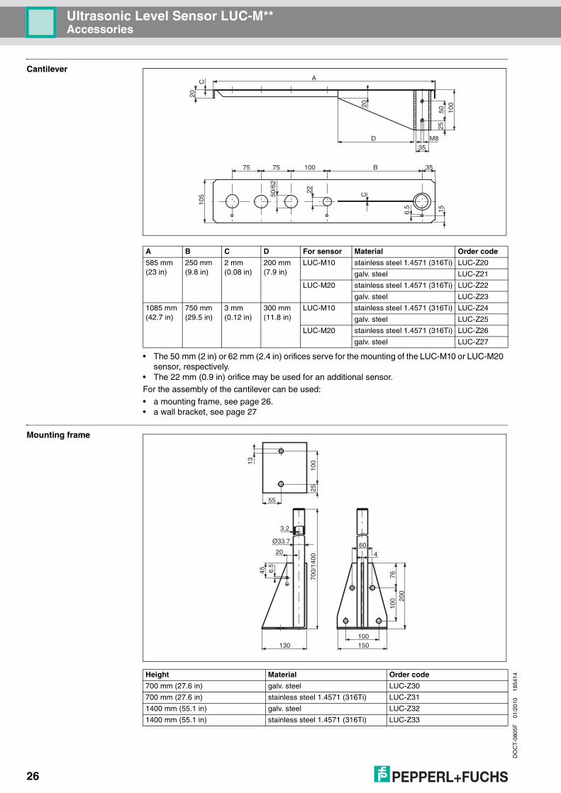
Cantilever
• The 50 mm (2 in) or 62 mm (2.4 in) orifices serve for the mounting of the LUC-M10 or LUC-M20 sensor, respectively.
• The 22 mm (0.9 in) orifice may be used for an additional sensor.For the assembly of the cantilever can be used:
• a mounting frame, see page 26.• a wall bracket, see page 27
Mounting frame
A B C D For sensor Material Order code
585 mm(23 in)
250 mm(9.8 in)
2 mm(0.08 in)
200 mm(7.9 in)
LUC-M10 stainless steel 1.4571 (316Ti) LUC-Z20
galv. steel LUC-Z21
LUC-M20 stainless steel 1.4571 (316Ti) LUC-Z22
galv. steel LUC-Z23
1085 mm(42.7 in)
750 mm(29.5 in)
3 mm(0.12 in)
300 mm(11.8 in)
LUC-M10 stainless steel 1.4571 (316Ti) LUC-Z24
galv. steel LUC-Z25
LUC-M20 stainless steel 1.4571 (316Ti) LUC-Z26
galv. steel LUC-Z27
A
D M835
50
20
2010
5 50/6
2
22
C
C
15
100
25
351007575 B
6.5
Height Material Order code
700 mm (27.6 in) galv. steel LUC-Z30
700 mm (27.6 in) stainless steel 1.4571 (316Ti) LUC-Z31
1400 mm (55.1 in) galv. steel LUC-Z32
1400 mm (55.1 in) stainless steel 1.4571 (316Ti) LUC-Z33
20
55
100
2570
0/14
00
45
7610
0 200
13
130 150100
460
3.2
6.5
Ø33.7

Ultrasonic Level Sensor LUC-M**Accessories
DO
CT
-080
5F01
/201
018
5414
27
Wall bracket
Adapter flange forLUC-M10/LUC-M20
Version with metrical thread
Version with conical thread
Material Order code
galv. steel LUC-Z50
stainless steel 1.4571 (316Ti) LUC-Z51
110
25
5
150
3,2
110
13
150
180
~21
3
~88
6.5
Ø33.7
Process connection
F73 DN50 PN16
F93 DN80 PN16
FA3 DN100 PN16
XXX other process connections
Sensor thread
G5 G1½, ISO 228
G6 G2, ISO 228
Material
S stainless steel 1.4435 (316L)
P PPs (Polypropylene)
LUC-Z- product designation
Process connection
A61 ANSI 2", 150 psi
A81 ANSI 3", 150 psi
A91 ANSI 4", 150 psi
XXX other process connections
Sensor thread
5 1½ NPT - 11.5
6 2 NPT- 11.5
Material
2 stainless steel 1.4435 (316L)
7 PPs (Polypropylene)
LUC-Z- product designation
sealing ringEPDM(supplied)
adapter flange
sensor nozzle

Ultrasonic Level Sensor LUC-M**Accessories
DO
CT
-080
5F01
/201
018
5414
28
Universal slip-on flange for LUC-M30
Remote display
Technical data
Prozess connection
FA3 DN100 PN16
A91 ANSI 4", 150 psi
J20 JIS16K100
Material
P PPS (Polypropylen), max. 1,5 bar abs.
L steel, varnished
S stainless steel 1.4571 (316Ti)
LUC-Z- product designation
Max. cable length 20 m (65 ft) (fixed length with connection plug)
Temperature range -30 °C...+70 °C (243 K ... 343 K)
Degree of protection IP65/IP67 (housing), IP68 (cable) acc. to EN 60529
Material for housing housing: aluminium AL Si 12, cable glands: nickle plated brass
Dimensions (H x B x T) 122 mm x 150 mm x 80 mm/4.8 in x 5.9 in x 3.2 in
Variant Order code
Remote display with on-site operation, cable 20 m (65 ft) LUC-Z40-NA1A
Remote display with on-site operation, cable 20 m (65 ft), with mounting bracket 2" LUC-Z40-NA1B
Remote display with on-site operation, cable 20 m (65 ft), 2G EEx ia, 3D LUC-Z40-EX1A
Remote display with on-site operation, cable 20 m (65 ft), with mounting bracket 2", 2G EEx ia, 3D
LUC-Z40-EX1B
Made in
Ger
Made in
Germ
an
many
M
aulb
y M
aulb
urg
urg
82
106
122
120
max. 80min. 30
96
88
160
118
180122
150
80
Separatehousing(IP65)
F12 housing (IP68)
Cable
Wall-mounting(without mounting bracket)
Pipe-mounting(mounting bracket and plate
supplied optionally,see product structure)
pipe
6.3
8.5

Ultrasonic Level Sensor LUC-M**Accessories
DO
CT
-080
5F01
/201
018
5414
29
Display and operating module LUC-Z15
LC display for on-site operation of LUC-M** (LUC-Z15)
Service adapter for communication with PACTwareTM, on request
Profiboard to connect a PC to the PROFIBUS
Proficard to connect a Laptop to the PROFIBUS
E+–
LCD(Liquid crystal display)
3 keys
Snap-fit
Symbols

Ultrasonic Level Sensor LUC-M**Supplementary documentation
DO
CT
-080
5F01
/201
018
5414
30
Supplementary documentation
Operating manual Depending on the communication variant ordered, the following operating manuals are supplied with the device:
These instructions describe the installation and first commissioning of the LUC-M**. From the operating menu, all functions are included, which are required for standard measurement tasks.Additional functions are not contained in the manual.
Description of device functions
BA 240OThis contains a detailed description of all the functions of the LUC-M** and is valid for all communication variants. This document is located on the supplied documentation CD-ROM in the form of a pdf file. It is also available on the Internet at www.pepperl-fuchs.com.
Short instructions KA 183Ocan be found under the device housing cover. The most important menu functions are summarised on this sheet. It is intended primarily as a memory jogger for users who are familiar with the operating concept of Pepperl+Fuchs time-of-flight instruments.
Communication Operating manual
4 mA ... 20mA, HART BA 237O
PROFIBUS PA BA 238O

Ultrasonic Level Sensor LUC-M**Supplementary documentation
DO
CT
-080
5F01
/201
018
5414
31
Safety Instructions The following safety instructions are supplied with ATEX-certified device versions. If the devices are used in explosive areas, comply with all the specifications in these safety instructions.
Version Certificate Communication Housing Safety information
LUC-M10-**A1*-IH*-EXLUC-M20-**A1*-IH*-EXLUC-M40-*A1*-IH***-EX
¬ II 1/2 G bzw. II 2 G EEx ia II C T6 HART, 2-wire F12 SI 174O
LUC-M10-**A4*-IH*-EXLUC-M20-**A4*-IH*-EXLUC-M40-*A4*-IH***-EX
¬ II 1/2 G bzw. II 2 G EEx ia II C T6 HART, 2-wire T12 with overvoltage protection SI 224O
LUC-M10-**A1*-PA*-EXLUC-M20-**A1*-PA*-EXLUC-M20-**A1*-PA*-EX
¬ II 1/2 G bzw. II 2 G EEx ia II C T6 PROFIBUS PA F12 SI 175O
LUC-M10-**A4*-PA*-EXLUC-M20-**A4*-PA*-EXLUC-M20-**A4*-PA*-EX
¬ II 1/2 G bzw. II 2 G EEx ia II C T6 PROFIBUS PA T12 with overvoltage protection SI 225O
LUC-M10-**A2*-IH*-SXLUC-M10-**A2*-PA*-SXLUC-M20-**A2*-IH*-SXLUC-M20-**A2*-PA*-SXLUC-M40-*A2*-IH***-SXLUC-M40-*A2*-PA***-SX
¬ II 1/2 G bzw. II 2 G EEx d [ia] II C T6 • HART, 2-wire• PROFIBUS PA
T12 SI 176O
LUC-M10-*****-***-S2LUC-M20-*****-***-S2LUC-M40-****-*****-S2
¬ II 3G EEx nA II T6 • HART, 2-wire• HART, 4-wire, AC• HART, 4-wire, DC• PROFIBUS PA
• F12• T12• T12 with overvoltage protection
SI 179O
LUC-M10-**A1*-IH*-ESLUC-M10-**A1*-PA*-ESLUC-M10-**A1*-IH*-E2LUC-M10-**A1*-PA*-E2LUC-M20-**A1*-IH*-ESLUC-M20-**A1*-PA*-ESLUC-M20-**A1*-IH*-E2LUC-M20-**A1*-PA*-E2LUC-M40-*A1*-IH***-ESLUC-M40-*A1*-PA***-ESLUC-M40-*A1*-IH***-E2LUC-M40-*A1*-PA***-E2
• ¬ II 1/2 D• ¬ II 1/3 D
• HART, 2-wire• PROFIBUS PA
F12T12
SI 180O
LUC-M10-**A1*-AH*-ESLUC-M10-**A1*-DH*-ESLUC-M10-**A1*-AH*-E2LUC-M10-**A1*-DH*-E2LUC-M20-**A1*-AH*-ESLUC-M20-**A1*-DH*-ESLUC-M20-**A1*-AH*-E2LUC-M20-**A1*-DH*-E2LUC-M40-*A1*-AH***-ESLUC-M40-*A1*-DH***-ESLUC-M40-*A1*-AH***-E2LUC-M40-*A1*-DH***-E2
• ¬ II 1/2 D• ¬ II 1/3 D
• HART, 4-wire, AC• HART, 4-wire, DC
F12 SI 259O
LUC-M30-**A1*-DH*-ESLUC-M30-**A1*-AH*-ESLUC-M30-**A1*-DH*-E2LUC-M30-**A1*-AH*-E2
• ¬ II 1/2 D bzw. II 2 D• ¬ II 1/3 D bzw. II 3 D
• HART, 4-wire, AC• HART, 4-wire, DC
F12 SI 177O
LUC-M30-**A1*-PA*-ESLUC-M30-**A1*-PA*-E2
• ¬ II 1/2 D bzw. II 2 D• ¬ II 1/3 D bzw. II 3 D
PROFIBUS PA F12 SI 178O
Ultrasonic Level Sensor LUC-M**Supplementary documentation
DO
CT
-080
5F01
/201
018
5414
32
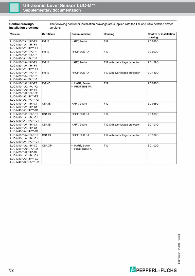
Control drawings/installation drawings
The following control or installation drawings are supplied with the FM and CSA certified device versions:
Version Certificate Communication Housing Control or installation drawing
LUC-M10-**A1*-IH*-F1LUC-M20-**A1*-IH*-F1LUC-M40-*A1*-IH***-F1
FM IS HART, 2-wire F12 ZD 096O
LUC-M10-**A1*-PA*-F1LUC-M20-**A1*-PA*-F1LUC-M40-*A1*-PA***-F1
FM IS PROFIBUS PA F12 ZD 097O
LUC-M10-**A4*-IH*-F1LUC-M20-**A4*-IH*-F1LUC-M40-*A4*-IH***-F1
FM IS HART, 2-wire T12 with overvoltage protection ZD 139O
LUC-M10-**A4*-PA*-F1LUC-M20-**A4*-PA*-F1LUC-M40-*A4*-PA***-F1
FM IS PROFIBUS PA T12 with overvoltage protection ZD 140O
LUC-M10-**A2*-IH*-F2LUC-M10-**A2*-PA*-F2LUC-M20-**A2*-IH*-F2LUC-M20-**A2*-PA*-F2LUC-M40-*A2*-IH***-F2LUC-M40-*A2*-PA***-F2
FM XP • HART, 2-wire• PROFIBUS PA
T12 ZD 098O
LUC-M10-**A1*-IH*-C1LUC-M20-**A1*-IH*-C1LUC-M40-*A1*-IH***-C1
CSA IS HART, 2-wire F12 ZD 088O
LUC-M10-**A1*-PA*-C1LUC-M20-**A1*-PA*-C1LUC-M40-*A1*-PA***-C1
CSA IS PROFIBUS PA F12 ZD 099O
LUC-M10-**A4*-IH*-C1LUC-M20-**A4*-IH*-C1LUC-M40-*A4*-IH***-C1
CSA IS HART, 2-wire T12 with overvoltage protection ZD 101O
LUC-M10-**A4*-PA*-C1LUC-M20-**A4*-PA*-C1LUC-M40-*A4*-PA***-C1
CSA IS PROFIBUS PA T12 with overvoltage protection ZD 102O
LUC-M10-**A2*-IH*-C2LUC-M10-**A2*-PA*-C2LUC-M20-**A2*-IH*-C2LUC-M20-**A2*-PA*-C2LUC-M40-*A2*-IH***-C2LUC-M40-*A2*-PA***-C2
CSA XP • HART, 2-wire• PROFIBUS PA
T12 ZD 100O

With regard to the supply of products, the current issue of the following document is applicable: The General Terms of Delivery for Products and Services of the Electrical Industry, published by the Central Association of the
"Elektrotechnik und Elektroindustrie (ZVEI) e.V." including the supplementary clause: "Erweiterter Eigentumsvorbehalt".
We at Pepperl+Fuchs recognize a duty to make a contribution to the future,For this reason, this printed matter is produced on paper bleached without the use of chlorine.

Subject to modificationsCopyright PEPPERL+FUCHS • Printed in Germany
www.pepperl-fuchs.com
Worldwide HeadquartersPepperl+Fuchs GmbH68307 Mannheim · GermanyTel. +49 621 776-0E-mail: [email protected]
USA HeadquartersPepperl+Fuchs Inc.Twinsburg, Ohio 44087 · USATel. +1 330 4253555E-mail: [email protected]
Asia Pacific HeadquartersPepperl+Fuchs Pte Ltd.Company Registration No. 199003130ESingapore 139942Tel. +65 67799091E-mail: [email protected]
PROCESS AUTOMATION – PROTECTING YOUR PROCESS
TI365O/98/en/01.10FM7.1
DOCT-0805F 18541401/2010