technical i?o!l!bs national advisgry committee toe
TRANSCRIPT

.--.7 —-.. . . -
&
i..4(\)’
TECHNICAL i?O!l!BS
NATIONAL ADVISGRY COMMITTEE TOE AENNAlJTrG!5 ._
-.----
,,, ,,., . -. -’.,;:;“~--, .:>.=-2-..-—
-, . ... . .. .
.
.——
..- -:-.”
.—
-—-
-.-. -
-.
-----.—.—-... .-.+ -.
—

●
A
NATIONAL ADVISORY COMMITTEE YOR AERONAUTICS,,.-—— —-
TECENICAL NOTE NO. 859
.———— .—— -.
ON T“HE DISTRIBUTION OR’ STRESS IN A THIN PLATE!-.—
— .—..
ELASTICALLY SUPPORTED ALONG TWO EDGES Al? —-.
LOADS BEYOND THE STABILZTY LIMIT
By Louis G. Dunn-....-.-
.- ..
SUMMARY
This re~ort presents the results of an investigation.. ..___...on the distribution of stress in a plate elastically su~- ““ ““:;”-”
ported along two edges and suljected to compressive loadsin a direction parallel to the elastically supported ed”ges.
.
In section I methods are developed for calculating:” “; “-- ‘-.
1. The compression stresses at the median surface indirections parallel and perpendicular to the ...=...Z=applied load.
~.-.-----
2. Bending stresses -------~----
3. Combined bending and compression stresses..- —-—
4, The effective width of sheet acting with each—=—.—
stringer ,-.,..-—.—-
Section II presents the results of a limited nurnb~fiof tests on:
1. The wave form of the buckled plate with fnc.reas- .“---___ing stringer stress
a.
2. Compression tests on 24S-T. dural sheet and 24S-Talclad sheet
-.
A comparison between the assumed wave form and the.experimentally determined wave forms given in reference 4is indicated in section I. The calculated straias kave
--
been compared with the measured strains of reference 4- ---
The discrepancies between theory and experiment are dis-cussed in sections I and 11,

2 NACA Technical Note No. 859
INTRODUCTION●
A considerable amount of theoretical and experimentalwork has been done on–the stress distribution in thinplates at loads beyond the stability limit, as is evidencedby the r~ferences included at the end of this report. Thetwo important -factors which enter into the theoretical cal-culations are the amplitude and the wave form of the lmck-led plate as a function of the ratio of the edge stress tothe buckling stress. Several approximate expressions forthe amplitude have %een derived, (See references 3, 23and 5.) Calculations of the exact wave form after bucklingare extremely complicated even for simple cases; for exam-ple, a circular plate with a simply supported edge and sub-jected to a uniform compression load in the [email protected]”Qf thoplate (reference 6). For this reason, in the case of rec~tangular plates, it is customary to assume that the waveform after buckling remains constant and equal to that’ at _.buckling. .
The majority of investigators have assumed a waveform which satisfies the %oundary conditions of simplesupport along all four edges. This type of edge supportis very seldom realized in airplane construction sinco theedges parallel to the applied load aro usually. supportatiby some form of stiffener; that is, tho edges are elasti-cally supported.
For the practical usage of thin plates the distribu-tion of the median fiber stress and the bending stressi.s of importance. The first is important in the eftec-tive width calculations and the latter tn the calculationsof the maximum stresses for permanent deformations. Since”these stresses are functions of tfipat-e -curvature, it Isdesirable to have a reasonably close approximation of thecorrect wave form. The condit-ion of simple support alongthe edges requires zero bending moment at the edges;however in the actual case the bending moments along theelastically supported edges are different from zero.Also, the maximum compression stress at the median surfaoeoccurs at these edges, so that fo~ the effects of combi”nedbending and compression stresses it is important that theelastic support along the edges be considered.
—-
.-, -----
—. -.
In the present report a theoretical calculation hasbeen carried out in which the influence of the elastic .—
support has been taken into account. No attempt was made

NACA Technical Note No. 859 3
to calculate the exact wave form after buckling; it wasassumed that it remains constant and equal to that atbuckling. The deviation of the experimentally obtainedwave form from the aseumed one is shown in section II tobe quite small at relatively. high stringer stresses.Since the amplitude also checks the 6xperinental valuesclosely, it seems reasonable to &ssume that the calculatedstresses will be in good agreement with the actual values.
This investigation, conducted at the California Iristi-tute of Technology, was sponsored by, and conducted withfinancial assistance from the National Advisory Committeefor Aeronautics.
The author wishes to acknowledge hi? appreciaii-o”n forthe advice given by Dr. Theodor von E&rman during the prep-aration of this paper and to thank Dr. Esue-Shen Tsien forhis willing cooperation,and Mr. Alfred Slater for hisassistance.
—.
●
1- TiiEORETICAL DISCUSSION OF THE FROBLEM
.—
For a plate subjected to a uniform compression-loadalong two edges and elastically supported along the edgesparallel to the load [fig. lb) , the influence of the elas-tic support on the wave form at buckling, and on the buck-ling stress has been considered in reference 5. For GYI.U-
“metrical elastic supports the wave form at buckling isgiven by . ..
w = [A cosh ay + B cos @y] sin ~x (1)where:
—-----
~ .J!QJ’ ‘–-
--—/~a Cc t .’? 7;
+J~~ 2
6 ‘J%~Rs=T ‘ k ;--- ‘“”””-“f
% buckling stress, pounds per square inch -—.
,..

4 NACA Technical ifote No. 859
v Foisson~s ratio,,
m number of half waves
t plate thickness, inches.
e, plate length,. inches .,
.
—
-b plate width, inches
If it is.again assumed that the wave form after bucklingremains the same as at buckling, the distribution of com-pression and bending stresses can be calculated. Sincethe boundary conditions at the edges are given fn terms
------
of displacement of the median surface of the plate, it is--
convenient to deal with displacements rather than stress.For the plat~the following assumptions are made: ...,—
\(a) The plate under consideration is one of the panels __
of a continuous plate attached %0 stiffening elements of“*equal flexural and torsional rigidity, spaced’ a distance b
apart. (See figure la. )
(b) The length of the plate is large in comparison toits width b, so that its behavior-is not ii~fluenc~d by-length,, .
..
Then the boundary conditions along the elasticallysupported edges are:
u + ~st x= O at y = +;
v =Oaty=&~’
w= QO at y= ~
aad In the x direction
w= O at x= am
(2)
(3)
(4)
..-— :
(5) %
(51) *_,
where u and v are the displacements of the medianplane of the plate, in -directions parallel aad normal tuthe load respectively, and cst is the compressive strain”
-
in the stiffeners. In applying expressions (1) through,
(5!) to describe the deformations of the buckled plate, the
11

NACA Technical Note No. 859 5
conditions of ~ero curvature and constant displacement at* the nodal points x = a/m of the buckle are satisfied,
The conditions along the edge y = b/2 depend upon the< torsional and flexural rigidity of the stiffening element*
as well as the~t-of attachmenti- The “influence ofthe torsional rigidity is taken into account to some ex-tent by the assumed wave form. Since the plate underconsideration is a panel from a continuous plate, the v ,component is zero at the edges y = &b/2 by virtue ofthe continuity of the plate in the y direction. Thiscondition is probably closely realized in actual structuressuch as wings There the. sheet is continuous around the wing,or where the sheet is riveted to heavy fore and aft spars.
General expressions for the displacements u and vcan be determined from the equations of equilibrium
)
By substituting the relations of equations (7)
(6)
(7)
into equa-tions (6) the following two equations connecting u, vand w are obtained:
(8)

6 NACA Technical Note ’No. 859
{9)
-,
.
. Substituting expression (1) for w, equations .(8)and (9) become .
(10) *
+ ‘a Cosh aY sin @Y +- k3 ai%li ay-’co-s @y + k4 sin z~y]
-[ ~ sinh 2 ay. + k. co~h ay sin By +. k7 sin-h ay ~o~ py
. + ks sin 2fIY3 (11)

.NACA Technical Note NQ. 859 ‘7
By inspection of equations (10) and (11) it is apparentthat the particular integrals can be written with undeter-mined coefficients in the form:
u= sin 2@x[MI cosh 2c%y + M= cos 2~y + M3 sinh cty sin ~y
+ ~4 cosh CtyCOS,~~ + h!5] (u2j
.
v = cos 2@x~Nl sinh 2ay + N= sin 25y + N= cosh cty.sin ~y.
+ NV cosh cty sin ~y + Na sinh w cos $y (13)
The coefficients M and N are determined by direct sub-stitution in equations (10) and (11), and are as follows:
M4 = +Aq#’ql+v) “ M’=(a=+ i+)’
5-Aa(~ +V&) .#%pa -v~)
16@”- .—
43$If== “, p-@4+ (as+ @2)(f32+ up’)] ‘
(cc=+ p2)=
ITe=-Bqv(f - Be)
2?=--A3p(v$2- OF)
.16P.7 4(fP i-r)..
X8=” -.&(q32 +..E12),,. “4(@2+i32)
,.The particular solution OY the differential equat~on5
(10) and (11) gives theprimary displacements’ ,U “and vdue to bending. The complementary solution of the homoge.

8 NACA Technical-Note No. 859 .
neous differential equattons (that is, the equations ob-tained by equating the right-hand side of equations (10)and (11) to zero) gives the induced displacements due tobending.
In ~iew of the boundary condition (51) the appropri-ate complementary solution can be shown to b-e of the form
u.= L(CIt + car) Cosh =VfY ,.
+ Cal 2@fy slnh 2@y1
sin 2@x - c xBt .L.—
72 - 2VQ =
1( )~-z-; c=’ - C1l. sinh 2@Y
-Gal 2fjy cosh 2#Y1
cos 2fJx + e}yy
The gen-eral e-xpressions for the displacements u anct v ?’can now be written as
[
— .-
(C I + C; ‘,)cosh 2@y i- Ca ~ 2@y sinh 2@y—
u=1
-1-Ml cosh 2ay + Ma cos 2py + M3 sinh ay sin ~y-1
+ ~4 cosh ~y COS’@y,+ ~]SiII ?@X,- ~StX (14)
+ xl sinh 2ay + N sin 2~y + Naq
~ cosh ay sin py
+ N4 sinh ay cos ~yJ
Cos 2tix i- N sinh 2ay + N ~ sin 2@ys
+ N7 cosh ay sin (3Y+ Ne sinh ay co’s @y + ei.yy (15) ,
Since the-boundary conditions indicated by expres- *sions (2) and (3) must be satisfied for all values of x,’it is necessary that the terms of expressions (14} and(15) included in the square bracket~, vanish when y = Ab/~In addition, the boundary .condition (3) requi.ms that .thoremaining terms ,of expression (15) vanis~ when y’= +b/2.From these conditions the constants Cl! and C21 , and~y\ can be determined, their respective values being .. .-.)

N.ACA Technical Note ‘No. 859
Gxt =3. Y Fz sinh @b + Fa cosh @b
1
-—--— -—- —--- ——-—-— ——— (cosh @%cosh @b f~$ sinh @b cosh @b - @b
1
CJ =-3 Fz sinh @b + Fa cosh @b—-—-.—-—.--.—--.———~;~ sinh @b cosh ~b - #b
~ ‘N5 sinh cxb + N=‘tY=-bl sin f3b+ NT cosh & sin &
,+ N~, sinh a+ cos ~
where 1
I?z = Ml cosh ab i- Ma cos ~b + M3 sinh ‘& sin &
. .
+ M cosh ‘& COS &+ ~4’ 5
Fa = NI sinh ab i- Na sin @b + N3 cosh a; sin ~
.,. :+N4 sinh: a+ COS .&
The constants appearing in the expressions for uand v are now all evaluated in terms of the quantities,A, B, ‘a, p, and ~. Therefore, the stress at anypoint on the median surface of the plate in the direc-tions x and y can be calculated– in terms of thesequantities from the following ‘expressions:
.
.“.,. .
—
1-v01@
2 aY
(15)
.-,’

10 NACA Technical Note No. 859
where Es is Youngls modulus for sheet
a,
‘()]+’lv&
2 a xl
Substituting in equations (16) and (17) the valuesv, and w given by expressions (l), (14), and (15)
Es fCJx = ‘=— (~4t + ~5t) COS 2fjX +j?et + F,f COS2 (jXI- vaL
(17)
of u,gives
-1
‘+l;~8’ sins @x+ et - VcJ
(19-)where: Y St
FA! =[(Cl’ + C2t) cosh 2@y + Car 2#y sinh 2@y
-1-Ml cosh 2ay + M2 cos 2~y + M= sinh ay sin #jy
+ M4}
cosh ay coe @y + M= #
+ H$a sinh UY SiZl $Y + fJcosh ~y COS ~y)
+ N4 (a cosh ay cos’~y - ~ sinh ay sin ~y)1 *
Fe! = V[N5 2a cosli 2ay + NG 2~ cos 2@y + N7(a sinh ay sin @y-.
.
+ ~ cosh ay cos ~y) + Ne(a cosh ay cos $Y - ~ sinh w sin fly)~
~Ft
7 = ~ (A cosh ay + B cos ~y)a $
Fe~ = $~(Aa sinh ay - 3(3 sin ~y)a
-d

NACA Technical Note No. 859 11
.
*
Before any numerica Z calculations of the stresses Oxand
%can be carried out it is necessary to first eval-
uate t e quantities A, B, a, p, and @. The constantsA and B can be evaluated from the boundary conditionof expression (4) and the condition that at y = O and
X=a the deflection w‘G’
is equal to the maximum ampli-
tude wo. Erom these conditions the following values for—
A and B are obtained:
[
Cos p
A= To —
COS f& - cosh a+ 1F cosh ~b
B =.L
r‘o ‘—
———
COS & - cosh ‘$ 1
(20)
(21)
TO evaluate the maximum amplitude, Wo s another ~boundary condition is necessary. At the pnint y = Oand x = a/m an emptrical ox-pression for the ‘stress a-%
{ acr)
1/2the median fiber of.the form ?X = acr ~ ~~ appears
to be in fair agreement with the experimental evidence ofiefereilce 4. The comparison is shown in-figure lc.
., In the expressions for a, ~, and ““@ the only ‘un~known quantity for a given panel is”the.half-wave lengthIt is therefore desirable to determine a general e~res-SiOil for A. When dealing with a plate of large a/bratio, the wave length of a buckle will not “be influencedby the plate length, but only by the plate”widt’h aad theelastic support along the edge”g y = *b/2 . Hence, forlarge a/b ratios, the ratio of the half-wave length tothe plate width can be calculate’d..-asa function of theparameter ~, where’ .
Ft%1A=*= —12(1-V2)C
The method of calculating ~ is given in reference 5.
‘—7+l+-
?i.
—
—.
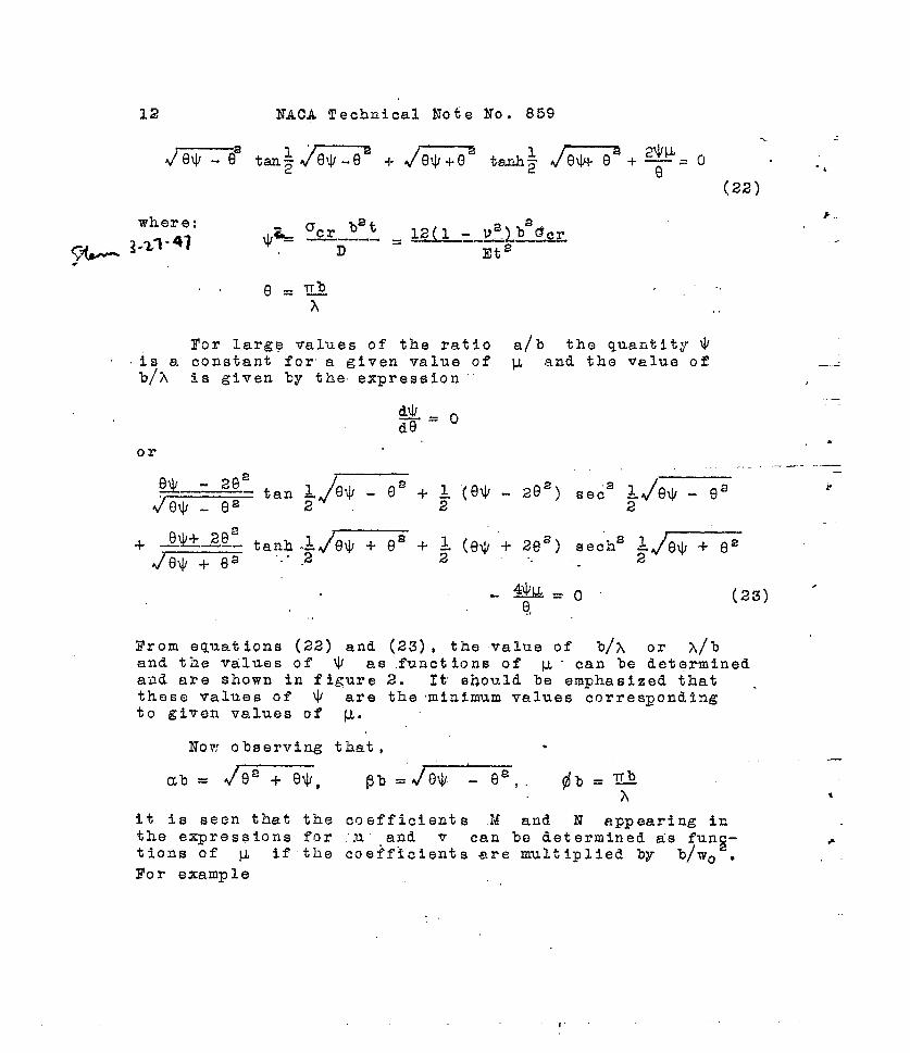
The critical buckling stress of the sheet betweenstringers was shown in reference 5 to be given by the tran-scendental equation . .,
where:
(22)
bet~-~ acrD.—-... . RQ_-Q.Qb’%rEt2
-.-.
..
.
For large values of the ratio a/b the quantity ~i.sa constant for a given value of ~ and the value ofb/A
— —is given by the expression “’ ,
dJ=Ode
—
or,*
4J.&=o.0,
(23) ●
From equations (22) and (23) , the value of bj~ or A/band the TalUe S of W as .functIons of v - can be det.grminedand are shown in figure 2. It’ should be emphasized that .these values of $ are the minimum values correspondingto given values of ~.
it is seen that the coefficients M and N appearing inthe expressions for “,u”,and v can be determined a’s funtions of v if the coeff~cients are multiplied by ~- +
b/w. ● ,-For example

NACA Technical Note No. 859 13
$ Cos p %M=J.L W08
[—- -—-. ----—. —
16 16 cOS ~- cosh~ 1(24a)
2
w=mrC’os p
Wo z 16 L=os ~~ - ‘—cosh a~2 2
78
1 “(24b)—
a~d since @b, a% and ~b are all known for a given value
Ml bof ~, the quantity - can be determined as a function
Wo
of ~. All coefficients hate been evaluated in this formand are shown in figures 3 to 6. The constants dz~ andcat can be evaluated in the same manner.
In order to simplify the necessary calculations it iss desirable to write the functions 1’4~, FJ and so forth,
in such a form, that they can be evaluated as functions ofthe parameter y. It can be seen that if these fu~cti.oi~s
w
ar-e multiplied by b2 the expressions (18) &nd--(19~ can-?
● Wobe written in the form
.
I
*“
EH WoacJx=—
(1 - Va)b’ [(~~ + F5) COS 2@X +,F6 + ~, cOS2~X
-f-F* sin=1.
Ijx+ velr “ !!!!s.. 1 1
Es Woa“(25)
‘Y= (1 [_ Va)w (VF4 +~~5) cos zfj~+ LF6--—-——
v(I
where /
= b2”ef.y b2Y4 T <“ baF5t
‘Y34=7
2F6 —-
2and so forth.
‘o ‘o ‘o
The functioris Pa, F5, F6, F,, and Fa can now be evalu-ated for various values of y as functions of the param-eter & and are shown in figures 8 to 12 inclusive. Theconstant ,% is independent of y and is shown in figure7 as a function of ~.

1-4 NACA Technical Note No. 859’
.,“
The amplitude’ W. can now be evaluated from the con-..
dition that at y = O and x =-.a/,m the =tre~, Ox = O= ‘~;~0 s
Writing for c~t its equivalenta~t
and noting that E.1;
W()in equation (25) applies to the sheet, the value of --
bis obtained as follows:
or
c St stringer stress, pounds per square i,nch
E Youngis modulus for the stringer, pounds ”~er:squareSt \nch
E Youngts modulus for the sheet, po,unds per square ’inchSr ,, .r9 =
1l?.!+ i’s + I?e + F7 + Vey
1
..
y=o
The e~ressfon for Fe can be evaluated as a function ofthe parameter ‘u and is shown in figure 13. Substitutingequations (25) and (26) gives .
..
F
b3s
-<
~st (1-V’2)~cr .B:; -\
ox = --———<“~-~, ‘~ -Ee )
[(% -J->5) Cos 2dx + Y6
1
. E5 ts~t+ IY7.C082 fjX +F8 Sin’ @x + U’% - — (27)
(l-Va) Est
Es !’0st0
(l-v’) ocr& “———— —- - ..—
Y )—~ \(vF4 + ;F5)cos 2#x “
= (1-v’) Ye b5t Es L
+ ;Fe, +vr,1.
COS’ @x + ~ F= sin’ @x + .Y - ‘Es ‘fst (28)v
(1-@)Est
I -#

--
NACA Technical Note No. 859 15-z. .-
The actual load carried by the plate for a given stringerstress and also the effective width can. now .be calculated.The total load carried by the plate is given by’ -
,
.—.
and the effective width is by definition.,.
.—
J.
2 we t Cst = Zt Oxdy’- “o,,
i- or the ratio of the effective width to the plate”widtk is
,*●
.
i
Substituting for .CT= the expression (18) and inte-
~st b+v~l h+ F&pzrla @x - —--.. 2. Y5 1
,>”
-..-2z~$- sinh @b +“@bC21(l-~) cosh @b----- ..-:.
.
where:.-
yt=10 (l-lJcl’ +, ., (
.
) (+ ~Jj+vN ) (~!!! + v~aa 1
sinh ccb +$ )
6in ~b + [a+ aM3
.
+ pM4) -1-VM31
CO sh
1einli a# cos & +.db M5 .,+ U174J, ..,,. . . . . . .
., . ...’-.-
.—
.

16 NACA Technical Note No. 859
-.r
F1
t=v~11 ~sinhczb+Ne”sin@b . .
“1-“N, cosh ~ sin ~~ + N8 sinh QQ cos ~..’ 2 2 2 1
P &~(A’ + 32) + &.11.2’=24 4a
sinh ab + ‘~ sin p’b4$
2AB-t-
<
ab $b ctb-- a sinh ~ cos ~- + j3 cosh ~- sin m
a= + P2 12)”
If the expressions foi FIO1 , I!lz[, and so forth, are
multiplied by A the above equation can be written fnW02
t-he formb ia
x’~* COS2 fix
where ey = ~=. ...—~ey, F ~F \Wo 11 = , and so forth.
wo~ 11
Substituting the above expression in equa63.on (29) (,noting
that OSt is negative and Tll = - v+) and the value
for ~– from equation (26), gives,
[
3 /2
We
‘--- - Ye)” -’1 k [’.0 Cos 2“XEs-- =-
b (1- V2)Est
2 @x + F13 sin2i
@x] + ;C:%E=+ F.la Cos (30).
-..
—.
.

-.
NAC~ Technical Note No. 859 17
s
●
As indicated by equation , the distribution ofthe stress across the plate also Varies ’in & lengthwisedirection. The total load carried by the plate..is given%y the stress d-is.tribution at the nodal lines. For exam-ple, if a stiffened plate is tested in compression, t-hetotal load on the plate as measured in the test, is that ~which exists at the head of the test machine, namely, at
—
a nodal line. The variation of the transverse stressdistribut ionsbetween nodal lines is balanced by inducedshear stresses at the stringer, and does not influencethe total load carried by the plate. However, the com-pression stress i.n the stringer will be influenced tosome extent by the lengthwise variation of the plate.,stress; that is, the total load in any transverse crosssection of a stiffen~d panel being constant , any varia-tion in the sheet load must be transferred to the stringer.
—
This means ,that the compression- stress in the striziger7 will be influenced by the lengthwise variatton of the”
plate stress, The extent to which the stringer stress, Fill. vary between nodal” points of the plate, will de~end
* “on the ratio of the stringer cross-section area to theplate cross- section arena.’ . . .
‘,The transvers~ stress distributions at ,the-~odal lines
and at the maximum amplitude positions hqv~ been calculatedin terms of the ratio Ox/Ocr for w=O &nd ~ “= ~“, andare shotin in figure 14. Although at the nodal.points aconsiderable difference in stress intensity occurs at cer-tain values,of y,” in going from U = O to. i-.= ‘s thisdifference occurs only over a narrow region so that thetotal load carried by the plate i.s not greatly affectedby the elastic support along the edg~s.,. At a stringerstress of 10 ti,rnesthe plat’e buckling stress, the simplysupported plate carries 19.5 percent less load than the
—
one with clamped edg6s* - .-
I!he distribution of the Ox stre”sses at x = a2m
is influenced to some extent, by the” Induced- transverse,. ,.
● stresses. As shown in figure “14, at the centsr of thetI buckl~ the stress,changes tci tension for the edge aondi-
tio”n & =’0; whereas, for ~ ,= = there is no ap~-reciable.change. However, in the latter case the edge stress -isconsiderably reduced; whereas,” the edge ‘stress for p,= C)changes only slightly. This titinsverse stress distribu-tion is primarily of interest in the calculations of themaximum combined stresses, for the maximum bending stressesoccur along the line x = S.
2m—
As previously pointed out the distribution of stress

18 N.ACA Technical Note No. 859
at the nodal lines gives the actual load carried by theplate and any vari~tion of the stress distribution be-
h
tween the nodal lines is balanced by shearing stressesat the stringer. Therefore, the effective widtih of sheet ?acting wit,h each stringer would be given by equal ion (30),when #x= 1, 2, 4, and so forth, or
(3T)
where
The values of F14, for various values of ~, are shown
in figure 15. If the calculated effective-width is to becompared with experimental results, further considerationmust be given to the method in which the experimental re-
*
suits are obtained. Trom the previous discussion it Isobvious that the compression stress in the stringer is not ●
constant along its length but is a minimum ab the nodallines of the plate, and a maximum at the maximum amplitudeof the plate. To obtain the experimental values of effec-tive width~ it is only necessary to measure the stringerstress corresponding to a given total panel load. Theload carried by the plate alone can then be determined,and by the &efinition of the e-ffective width, its valuobecomes immediately calculable. However, if the stringerstr’oss is not constant along its length, the effectivowidth thus determined would be a function of-the positionat which the stringer stress is measured. The eqcrlmen-tal results given in reference 5 wero ‘obtained by averag-ing the measured strains, employing from 8 to 18 gages .
mounted as sho?m in figure 10, of refererice 5. It iS likely
that the average of these measurements closely representsthe average strain in the stringers. H-ence, the experimen-tal results thus obtained should be compared ~ith the cal-culated effective width corresponding to the integratedmean value of the plate load betneen nodal lines,
Arather
than the load existing at the nodal lines. The effectivewidth based on this integrated mean value of the load canbe obtained immediately from the integrat~d mean value of
P
eguati.on (30) ,that is, ,
. .
1,

NACA Tech.nical. ~ote No. 859 19.,. ,..---
.
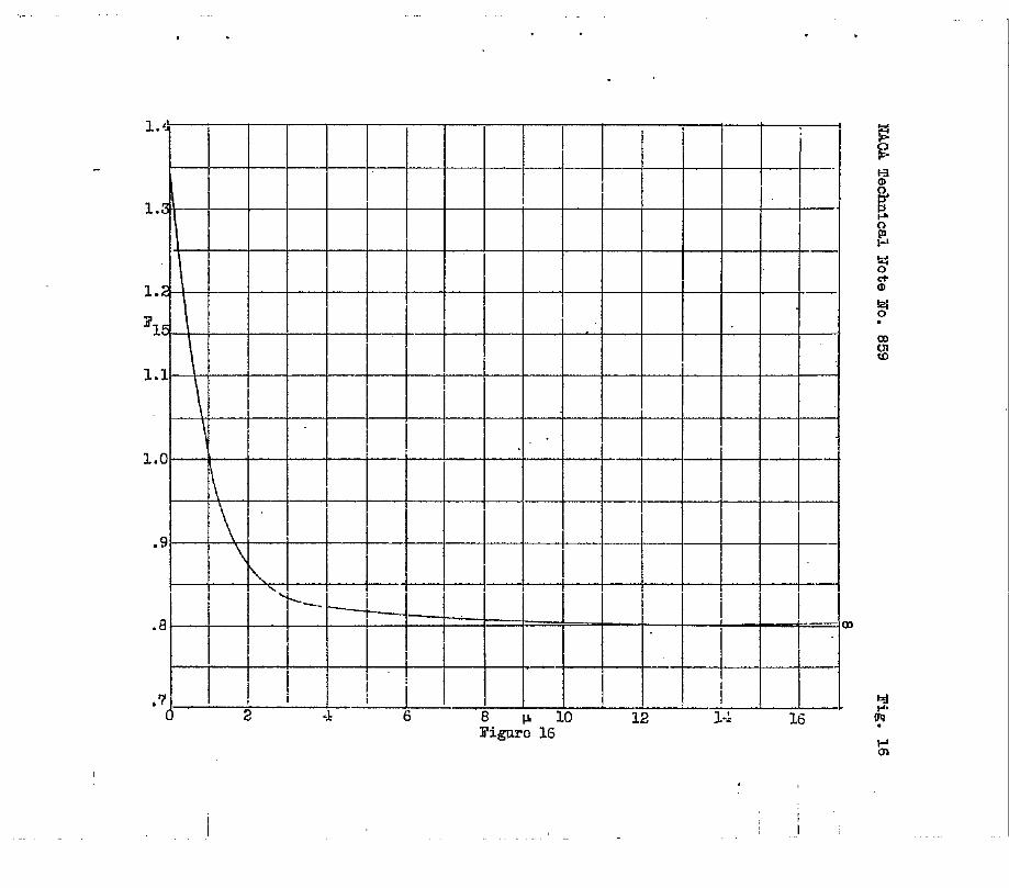
()We%- mean =.
whereFla + FI’3
F15 =2
.“-,,
The value of F , as a fu”nction of v, is indica~ed ““
in figure 16. Assum~~g Young!s znoduli to be the same. forthe plate and stringer ,the mean effective width curves forthe two limiting conditions, that is, w = O and v = ~,
-.–-
are shown in figure.1,7. The.”effective width values givenby equation (32) aye slight”ly lower ”than those given byequation (31), the maximum difference being of the orderof 6 percent.
Zn calculating the effective width for,any platastringer cor.bination, it should be ke~t ,in mind that thetorsional rigidity of the stringer varies ae’ost ~ncreasess
Since both F9 ..and,F15 are fupctio,ns ~o”f ~ it is neces-
sary to, correct’ t’~ese quantities for”the change in tor&ion-al rigidity of the st,ringer as ~st ‘incr”eases.””--Equat ion
(25) of reference 5 can be written in th~ form.,. .. .
where ,.,, . .. ....
JEst Young~s modulus for t~e string6r ..
.--. .-—
-+ CBT ‘torsioq bending constant (re~erences 31 and l~.)*-. . .,. . . .
ox axial compressive stress in the stringer,,
~
P.polar. momeht”ofui~e~tia of t,h~ st;iqger” seation
about the axis “9f twist ‘~——- — ——----I-——-7—--F-- -—-—-.,-.“. .... .*See appendixA, for .exaaple.

20 NACA Technical Note No. 859
c torsional rigidity of the, stringer
‘I-Lsin ~.Z moment transferred by the %uckled plate toa the strfnger
@ unit torsional deflection of the stringer
Neglecting end effects, a solution of the above equa-tion odn he written in the form
@ . ~ Sj,n ‘?3?from which a
A= k—--- .- -.—------
TT T]‘st CBT !QllA + (C-OXIP) fi a
a a
(34)
Since the amplitude A is a measure of the torsionalstiffness of the stringer the ratio
(35)
would be a measure of the change of the torsional stiff-ness of the stringer, where Cr is the redu”ced torsionalstiffness of the stringer and A. corresponds to” Awhen .Ox= 0. This equation then allows a calculationof the variation in torsional rigidity of the etri~lgerwith increasing stress.
The experimental values of effect-e width for a num-ber of panels have l)een compared with the results givenby equation (32) and are shown in figures 18 and 18a.The curves are the calculated values corrected for t-hechange in torsional stiffness of the stringer with increas-ing str=ss~ and taking into account any difference betweenEs and Est. AS indicated by this comparison, the cal- ●
culated results do not compare ‘favorably with the experi-mental results. This is particularly true for the torsion-ally weak stringer. Although t-hg correction for reduced
r
torsional st=lffness of the strimger recognizes,achangein wave form of the plate with increasing stress, it isfelt that the magnitude of this correction doeg not fullyoompbnsate-”for the actual chang6s in wave f-o.rmwhich mayoccur. It is believed that this is the principal cauee ofthe deviation of the calculated values. It should also he
,.

NACA Technical Note No. 859” - 21
noted that the derived equations are OnlY v~lid belo~ theproportional limit. It has been FroposedL in literatureon the subject of effective width, that above.the prop~r-””tional lirni$ it is only necessary to replace Es by Es-.where Es is the secant modulus. Th-is is a fallacy, for
only that portion of the’ sheet subjected to stresses abovethe proportional limit is affected by the change in E.The distribution of stress in that portion of the sheetsu%jected to stresses below the proportional limit remainsunchanged. Above the proportional limit it is necessaryto make a point-by-point correction for the reduced valueof E. It will be appreciated that a blanket applicationof the secant modulus w%ll reduce the stresses throughoutthe entire sheet and thereby incorrectly reduce the effec-tive width. In figures 19 and 20, a point-by-Eointc or-rection is illustrated for the J-section panel with .040- ““24S>T alclad sheet. The method corisist’s essentially of acalculation of the strain E=’ ,,at the median fiber in
the x directio-n, where———. .
<x + Vcy~xf = y~-
. -(39) _
The working expression for g=! was obtained directlyfrom equations (16) and (i8). This strain distributionwas then plotted and the corresponding stress in the sheetobtained from the stress-strain- curves of figures 36. Ofcourse, using the stress-strain curve obtained from a uni-directional load is not strictly correct. However, if Gyis small in comparison to ox the method should at leastapproximate the correct “stress distribution. A study ofthese curves indicates that the reduced E, above the pro-portional limit, is not sufficient to account for the .&is-crepancies of the effective width caz~ulations indicatedin figures 18 and 19. Of cotirse, the above method doesnot consider the effects of the induced bending stresses.The dimensions of the stringers are shown in figure 42,and the stress-strain properties in figures 36 to 40. (Thedata on the J-secti-on was supplied by the Locklneed Aircraft
‘ Corporation) , . ... .-
The x components of the bending stress are computed”. as follows:
. .
%B =EZ M= “l-u’ D (3’?)

22 NACA Technical Note No. 859
where Z is measured from the median surface- of the plate.Substituting for Z its maximum value t/2 and for M=the expression
MX=-D.(
a%+vax=
equation (3’7) becomes .
aaw-—aya )
(38)
Substituting the expression (1) for w, equation (38)can be written in the form
whore ..
F . b: r A( V~=
1- ~’) cosh ay - B (vp~ -1-da) Cos py
1s W. 1
The function Fle has been evaluabd as a function of ~for a number of values of’ y, as indicated in figure 21.If both sides of expression (34) are divided by Ocr, itcan be written i’n the form,.
the above equation can be writt,en as
!!Jhisratio asstimes its maximum value when sintix= l.”
.
#
()OBHence & occurs along the line x = a and is
cr max . 2Y s
“’gf,~~~ by the. ~rac~eted parii’& of’ equation (%5) .
1.

.
NACA Technical Note Ho. 859 23
.
●
✎
.’
The sum of “this maxtmum bending stress distr~~ut ionaiid the com~ression stress dis,tributio”n given by .exp”r”es-sion (27) gives the maximum compression stress dis”trihu-
. .
Tak”ing ~tion in the x direction. = 10 and Est = x~,~cr
the maximum stress distribution has been plotted for u = 0.5and U = m, and is shown in figure 22. As seen from thisfigure, for the case of simply supported edges the maximumcompression stress does riot appreciably exceed the stringerstress over the entire panel width. The value of u =“ 0.5
.-
corrasponds to a stringer of highbtorsional rigidity andin this case, at the edge’s y = ~, themaximwn compression -
stress exceeds the’ stringer stress by approximately 2’? per-cent. This increase in the maximum Tlate compressivestress over the stringer stress will not affect to any ap-preciable extent the load-carrying ability of the sheet.
The wave form of equation (1) was compared with themeasured wave forms given in figures 27 and 28 of reference4, as shown in figure 23 o% this report. Both the trans-verse and longitudinal wave forms check closely with themeasured ones. In order.’to ~ke this comparison, the tor-sional rigidity of the stringers must be knovn. $t wascomputed approximately by assuming” the stringer rigidityto be the same as that 05 a rectangular plate having thesame cross-section area and thickness as the stringer’.
—.
By this method the torsional rigidity was found to”be 630inch-pounds per radian per inch. The corresponding valueOf w was 0.198, the wave length was determined from fig- -ure 2 and the maximum amplitude .from.equation (26). Thebuckling stress of-the sheet. was computed and found to be2500 pounds per square inch, which checks with the valueindicated in figure, 55 of reference 4.
.In view of the good agreement between the calculated
..and measured wave, formsj it is reasonableto expe~t also,.a good agreement between the calculated “and measuredstrains. Calculating tl$~ strain by the:equatton ~.
,..,..7. .
. . . . . . . . . . .’..

24 NACA Technical” Note No’. 859
the resulting values, et x =. ~ and2
are indicated in
figures 24 and 25, where they are compared with the mes.s-ured values given in figure 20 of ref%rence 4. The meas-ured and calculated strain distributions compare favor bly.
0.1$5 aThe transverse strain at the median fiber, at x = ~
has been calculated and is compared, in figure 25, with
the obsorved value at x = Q 15&-a, The agreement appearsto be remarkably good. m
II- EXPERIMENTAL RESULTS
Inasmuch as the wave form is one of the importantfactors in the theofeti.cal calculations of the stress dis-tribution in a buckled plate, it Is desirable to have someknowledge regarding its variation with increasing load.A number of tests were conducted in vhich the wave formwas measured for various increment-w of load. The measure-ments were obtained by means of a dial gage attached to aframe mounted on the bed of. the testing machine. The re-sults of these tests are shown in figures 26 to 33, wherethe deflections were plotted for various value~ of theratio o-f the stri.mger strain c~t to the sheet strain ccat buckling. The primary purpose of these tests was todetermine qualitatively the amount of change in the waveform with increasing stringer stress, The wave forms plot-ted in figure 29 indicate that there is in some cases aconsiderable change in the wave form”. ThB–change in wavefo!rm as indicated by these curves is somewhat irregular:for example, the 0.025 sheet changed but slightly in waveform; whereas the change in the 0.04Q sheet is more thanin the 0.050 sheet. It” s,eems there should be some degreeof consistency in the amount of change in the wave formas the sheet t-hickness increases.
It. is possible that the inconsistencies indicated bythese results can be attributed to t-he influence of buck-les in the ad~acent sheet panels. It iS difficult to es-timate the influence on,the compressive stress distribu-tion due to the amount of change in wave form as indicatedby the experiments. However, the Indicated flattening ofthe wave will cause an increase in the y component ofstrain tvhicb,in turn causes a decrease in the x compo-nent of strain.
,.
P
-—●
11

NACA Technical Note’ No. 859 25
The compression stress-strain properties of the 24 S-T.sheet material used in the above tests are shown in figures34 and 35. In addition, a number of compression tests were
& conducted on 24S-T alclad sheet; the curves for this mate-hrial are shown in figure 36. The method employed fn deter-mining the compressive stress--strain properties was identi-cal to that described in reference 7.
The stringer strain as a function of average stressis shown in figures 37 to 39 for the various panels tested.By average stress is meant the compressive load on the pan-el divided by its total cross-section area. The stress-strain properties of the stringers are shown in figures 40and 41; the section dimensions are shown in figure 42.
Guggenheim Aeronautics Laboratory, —
California Institute of Technology,Pasadena, Cal if. , June 1941.
. . .. . . . .
.
,,
.
.- —

26 NACA Technical Note
APPENDIX A
Xo * 859
The value of the torsion-bending constant,. C3T, may%s calculated either analytically or graphically. Con-sidering a general section such as that- shown in figure43a , the value of CBT is given by the expression
r
c,, =pi.-~wtq , _(42)
A A
where w is the circumferential warping and is given %7the equation u
w=f
rt du
o
In the above expression the cross-secblonal warping
‘n n has been neglected. Since n, at the most, is *eqaal to t/2, the warping rn n will, in ~ene.ral, be
small compared to the circumferential warping and may beneglected.
,.
In evaluating the warping w, the following signconventions have been adopted. A direction of rotationis chosen arbltrarfly;
.then the circumferential coordinate
u is taken positive in the direction of-rotation. Alsothe positive sense of rotation indicates the -positivedirect-ion of-the tangent to the “circumferential coordinateu. llrom the positive tangential direction, the positivenormal n points to the right and a line drawn from Oin the positive n direction indicates the positive rndirection. The angle ci fs measured in the positivesense of rotation, that is, from +x to +y. As an illus-tration, consider the channel section shown in figure 4311and first calculate c3t about the point O.
.
Choose the origin of u at O; then,
From 1 to 2 ‘t=*a
From 2 to 3 rt = ~ du is negative and w = -a&
From 1 to 4 rt = O
Yrom 4 to 5 rt = ~ du is positive and w = a$
,-,

NACA Technical Note No.” g59
from which..
b b
[wd.A = -a$
JUdu -1-&
JUdu = o
“A Ob ohence b
J
~2t ‘ aCBT-. ~ u du -f-~2&
I
aab3tuadu = ——4 6
0 0
“27
Now let c BT be calculated about the point OlaAgain, take the origin ‘of u at 0; then,
From 1 to 2 rt = +C du is negative, and w = -CU
3’rom 2 to 3 rt = ~: au is negative, and w = =~-a~
From 1 t; 4 rt = +C du is positive, and r“= cu
From 4 to 5 rt =. k du is positive, and w =,~~ I-a&.,, 2
+ 2b2(b i- SC)’
J
1The integral WdA will not be zero If, for example,
Athe origin of u is taken at point. 2. However, the alge-braic sum of the two integrals of equation (42) will alwaysbe’ constant for a given axis of rotation, ,th~t isi the ex-pression for % is invariant ~it~ respeqt t? the originof ‘the circuinferen’tia’l coordinate u. T“he origin of therectangular coordi.riates .= must, of course, be taken-atthe axis of rotation. Assume, for example, that the c&-ter of rotation of the section shown in figure 43c is atthe point O; then CBT is evaluated as follows:
Take the origin of u at point 4; then. from 4 to 3
rt =r+decos(3+b sin El
and u
w=4–3J
rtdu = rJ
(r+dcos0+bsin6)de
From 3 to 2‘t= r-d
and

28 UCA Technical Note No. 859
u
w 3-2 = ‘4-3 e=n+
i
(r- d)du = r2m+ 2rb + (r - d)u
Ii’rom 2 to 1 rt=o’
w ,=2-1
w’ =-ran + b(3r - d)3-2 “U=b
Hence i
cBIC = J“dA- :i--~qg =tr3~cr~+‘ ‘in e- b C!os 9
,L bA o a
+ 3]2[ J
d“9-1-t cram + 2rb + (r - d)ula du -1-t [ral-r
o v.+ b(3r -
Jd)]adu-~. rat [r0+dsin9-bcos6+b] dEl
A~ob
J-1-t [r% -1-2rb + (r - d)uj du i- t ~rzm + b(3r - d)~ du}’
;
where A ts the total cross-section area of the section.It can be seen, for exam~le, that, if the ori~in of thecircumferential coordina~e u is taken at ~oint 1, theresulting expression for CBT would be eonsidera31y sire-
plified, since the warping from 1 to 2 ~ould be zero.
When a longitudinal stiffener, is at+ached to a thinplate the rigidity of the plate requires that the QXIS of—rotation lie in the plane of the ~l~te.: In com~.uting
C3Tfor this condition, a number of values of
%cor-
respondiilg to various positions in the pi.nne of the _platewere conrput”ti, and a curve was then Flottod of CBT as
a function” of position. The minimum value of C~T ,wa’
then used in computing. the variation of torsional rigiditywith increasing load.
r
-“=+.
.
,.—
.
.
,.
1

.
. ..,
1.
2.
3.
4.
5.
6.
7.
8.
9.
10.
11.
NACA Technical Note No. 859
,. REFERENCES :
.29
,.
Marguerre, K., and Trefftz, E.: fiber die Tragf~higkeiteines l“&ngsbelasteten Plattenstreifens nach Uber-schrei.ten der Beullast. Z.f.aOM.M. , vol. 17, April1937, pp, 85-100. .
Zharguerre, Karl: The Apparent Width of the Plate inCompression. . T.&!. ~Oe 833, lIACA, 1937.
von K&&, Theodor, Sechler, Ernest E. , and Donnell,L. H.: The Strength of Thin Plates in Compression.A.S.M.E. Trans., APM-54-5, Vol. 54, ao. 2, Jan. 30,1932, pp. 53-57.
Ramberg, Walter, McPherson, Albert E., and Levy, Sam:Experimental Study of Deformatio~ and of EffectiveWidth in Axially Loaded Sheet-Stringer Fanels. T.N.~Os 684, NACA, 1939.
Dunn, LOUiS ~.: Ark Investigation of Sheet StiffenerPanels Subjected to Compression Loads with Particu-lar Reference to Torsionally ‘iTeakStiffeners. T.N.No. 752, NACA, 1940.
Friedrichs, K. O. , and Stoker, J. J.: The Non-linearBoundary Value Problem of the Buckled Plate.Proceedings of the National Academy of Sciences,vol. 25, 1939, Pp. 535-540.
Aitchison, C. S. , and Tuckerman, L. B.: The I’FacknMethod for Compressive Tests of Thin Specimens ofMaterials Used iu Thin-Wall Structures. Rep. No.649, NACA, 1939.
Timoshenko , S.: Theory of Elastic Stability. McGraw-Hi~~ Book Co., Inc,, 1536,
Timoshenko, S.: Theory of Elasticity. 1st cd.., McGraw-Hill Book Co, Inc., 1934.
Sechler, E. E.: Stress Distribution in Stiffened Panelsunder Compression. Jour. Aero. Sci., vol. 4, n“o. 8,June 1937, pp. 320-323.
Lundquist, Eugene E. , and I!’ligg, Claude E.: A Theoryfor Primary Failure of Straight Centrally LoadedColumns. Rep. No. 582, NACA, 1937.

30 NAC~ Technical Note No. 859
12. Kappus, Robert: Twisting Failure of Centrally LoadedOpen-Section Columns in the Elastic Range. T!.M.No. 851, NACA, 1938.
1 ‘m

●
. .
Technical Note No. !359
I11
II
II
I
1-
.
Y
I
I
-i__0
--— +-i __.L- 1 f’
Y’I
--lI[
I1
II
Pigs.la,li
pJ, v
II 1
.t
I‘ii :1, a
!I I II
It 1-
i[ ,LTv,. ‘
—xIe--n/2 -&b/2‘T4”
-.

* .I
● . .
Cfsq
q
Figure 1o.- Variationof~with&S~aty.O,x. &
.

a.!
w
‘7.(
I6.[
\
.—
‘1
.- /
1
. . .
Figuro 2
# .

. . .I
X104F
-2.5 - ,,”lT5b
iJj2
-2.0
-1.6 -
‘\
/ \
-1.0
i@’
n
-. 5 -
0 2
4
-t
—. .—
\
i
— \.
\\
—
\\ —
\\ \
---
i 1
.
L ~1
~ _
I I I ~
4 6 8 IL 10 12 14 16 ~
Fi&o 3
-.
.
Ga

. .
1:

s .

.
I 1 I 1

I. . .

. .I
.
-5.0
\
-4.()
d
‘4
-3.0 - ‘\
\.YF, O
1-2.0
‘L. —m+.-~.:_ -yTb “’
f—m
\
I
L
-1.0 -\ “Y=Q–
,{ 4~ _ -—. L t —m.. .—— 4.- .—. -—.
I
- +,,:
‘“ r,~~
P ,&—03
—— 9
4 6 8P 19 12 14 ‘ 1.5 W
~iglUCO 8 ~ ~“g K
i.m
,i 1 :1

.’ . . .
F/e 9
I,..
,,\
i., i.L

. .I
1.0”
I
\,
\
.5 -
l\
---— Y= 0 ‘\
~
— . . \F(j ~
—.-.\\ —-m
i y= b/8 - - ““
\ \ I
y=’ IJ4 .1
1.
0 -.. _.——— ..-
\% —m
.
~ _-1
-Y= b/2
-.-—
I
I~
— _—m
~
-J. ~/B -“
w
-. 5—-0 2 4 6 B 10 12 14 16 :8
?Igk 10 Po

.
,

.NACA Technical Note Ho. 859 I’ig.13
.
.
.
I I
I I1“
I
5“
\ .— —
\
[
I
-. I
1,
——.,
~
1’ ‘:.,
i— —.
-?1! I
/
\l\
3 . I ,— —— -.,-—\
I~-a.— —— -—
4
..— -.. — .
— — .
L-—
2 ! I I I I0 2 4 8 10 12 14
I’igum !3

I. ,.
#
.ss

.
+
1.3 ---
,
1.2
!
1.1 ~~
\I
1.0
\
‘1$I
.\
..—k
\‘1
—
\‘\.
. --%.—4. —
I I
1
—m—
J
.7 i ~
0 2 12 14 i6
Fi.glm 16
wOT.
,-
.
1.3
1.2
315 \
1.1
\
—
I . -1.0
.9
\
\\
.8 ,.——— In
~~ [“~,7 i
2 .1 6 8 10 li ~.~ 1611’7.gd 16
Ii.

, ~7ACATechnical Note Ho. 859 li’ig.17
.
.-
.5
.4
.3we%-
.2
~il
.4
.3— .—...—.
.2 I —!
●
.1–—
r
—— -.—..
Q1 1
2 4 6 9 10
.
.
.
,
.1
I
q--~i ~ ‘. L ;;
!
+-%
I—.
Ik
4’ -“ “-- ‘-
L—— —.. -—>.
—
.-
L
I
I
..
) 4$Q
6
—
—
I
L—-———..——--_—-,--.—.
10
Figure 17.- Moan offoctive width as a function.of% Ps = ‘~~)
.

.5
.4’
.3
.2
.1
0
.
-1
.
Stiffenerstressin lb per sq in.“,.
~ 5’igurelE.- ~ffectivoY,fidthcurve,3 stiffimarpanels, OKl 24S~ alclad sheet,J-mction 161 Pm.
II

.
5.5 ‘+
8 inch panels
+16 n n
.4
0 27 II II
.3
~~rop. limit of Wee”;
b
.2
.1 -
0c1 BIYCk3 16000 24000 ~~oq
Stiffener stress in lb per sq in.
Figure lsa.- Effective width curve, 3 stiffener paneh, .040 .24S Talclad sheet, bulb angle #6W7
I
1

. . I
‘ST
FigOre 19.- &%ial stress ~d strain distritmtlonbeyomiproportio& lir.~5.t. M~

i’
. . .
-S I--L-L--L--L-! !’”!E :.k.-..-!l---l--
Wfi- i , “01% i “i\.i’i
1 ,,m
:I
~ 30 — —yProp. Umlt,
*
o“l-l
XXICl
z
3m
U) . 1 —. .
I/
——
~ / i \ I,‘\x ./ ,/
II I \., J
0b] 2
II .4 b/2 bf2 4
esT =W)xlrl‘s!!
= 70 x 10-=b/2 ;
.
Figmo 20.- Axid strain and strms distribution beyond proportional limit 8.

NACA
/-
.
.
.
Fig, 21
--
-.
1+02
a5.
ii.+r%
.

NAOA Technical Note Ho. 859 l!ig.22
.
●
.
#
.
#
Fi&urcl22.
ri
I
13
12 , /
i,\
\
\
7—–
6 -—!
I
5
~
1?3
2
1tI
01 Ib/2 ,22
- Combined aXial stress distribution at x= ~~~ =
——-
—
—...

@kw #
TRAvSVEJ?SE ‘W6VE &
. . .
Wwv..k?d wal= m
L#GITUh!!L W@VE P2?M LavGf?umA4w wfv~ -~

. .
Panel load 68Q0 lb
-.-oalcukted at x . ~--- II n X=~.Z5E
o Ohservedat x= 0.152 ~&ef. 4)
16xloAtI
14
“1
% 2
:
~o -’< ‘.\/—,
~ / /41
❑ \\
!% \\ //
~a
/
(0 \
A\“/
56
~
\4
/\ /
\ /2 \\
o
b/2 .&. bf2
. ●
Figure 24.- Comparison of aalcul.ated tial strain distribution with experl.mental ;eauliis given in Kreference 4.
.
I ~
t,

.
22,@~*– ,
-.
“\-’ Pa 101 101l.d11, ,/’
\’ \ -calcu 3
18---. E
‘,0( )bsarv 3d at : (
\(ref. L)
16//I
\ I1.: <
I .-
FJ
$ \. $12 i
/g
\:10
~a /
c1’/
*\
t2 \ {!36 -.
\\ :/
4 . / ‘ .— .\ I\
2II i
Y’”
1// ,’,
0 \ ,. . ~ ,)
b) ,2,
‘.. ./.>. b/2
Axial strain &t ndian fiber
Flguro 25.- Compariwm of cakulatod strain diotri
.1
. .
,i ,,

. . .. 4
I

, .- . .

,-. . d .

* . d .

.
\
.
9
——

YMA TOOhDiOd IOtO MO. 859rigs. 36,87
~ -
I
.
\
—Q, — — —
~’ ,
1
I 1 r
/ /I I I/vlvll’lli+l
t I I I I IZ+nm
1
J ‘
I?z,ocu /
) H ‘ / “
,qooo //
. .
/ ,
illlly.. -, - .040
K’ / F /I I I I I 1.. .-L
‘j /6,0007
P/
II II III AI 1/6’ ‘“
~! 1111X11
d p
/
f
2,000
0
4J0’’l—b4—H—
.=
Ffg. 37

.
*
NACA Technical Note No. 859 Fig. 38-
15,000 I t I
I
I“
~
I
~ ) .Y ; ;“ ‘;’ “x ~
1, P
.025
t 0
i ,.(34010, WI
o ,
;+CJ / .A \a ‘-
~
5 ./’”/
1 —- / ‘m /:
Z5 ,003
i/
I
G
/1o Io 0 Unit strain - in. per ig.
- Figure 38.- Bulb angle 10265, 24ST-sheet, pcmol width = 15 in,, totalstringer area = 0!1910 w in. -—

P .A, , .
I
3 .-~ Er
/ Y Fi /’
10,GO3 / .C’” -_~
9
/’ -4w
SLX
?’ z/8,000
Q
I , / : ‘ ‘; / i. ‘ ‘ “:-
,%’
40
i.
.ri /1 in— –- —/Q--t-
Cii
w ,/”
to
2 .06,000
$A d - T-’ :;25
I
m-
m
2
$ ,000 - —
o
2,(x)f-1 . . 0
/Y
Pb’
1[ ! /1 i r -’l.0002 + :
“o o“$
Unit straig -,i,u. p~r @.
!~, ....
Ii&u&e 39.- Bulb angle 1, 24ST sheet, Pnol tidth,= 15 in., total stri~-or area = 0.1150 sq in.Gaw
I

IY
Y
—
xb
L+
(a)
(b) (c)
/vo/07i.m7* fm~on co/umn &7//um??
F/g, #

NAOA Technical Note No. 859 I?ig.41
#
s
1 5! I I Im )
I.
I I
I
—.
/
5 /i It
1 1
kt
I1
0 /1I
I9 .001 ‘ .002 .003 .Cw .005 .006 .007
Unit strainFigure 41
.
.

NACA Technioal Note No. 859x
,’
Bulb angle No. 847’7
d
*
~ 8“0625R
L
.500 _,Mo .(-MQJ, ~
‘1 /-7
+ “u81-Bulb angle No. 1
Fig. 42
. .—t-094 R
‘L
-0051.87’5
d-- Jo” --
km P
.——
-.
.-
—
—
--
T7)a.250R
1.2ECl
~–.750 -A ‘1. .—-—
J section No. 161
-.
.-