technical manual organizational and direct …radionerds.com/images/2/2a/tm_11-5820-882-23.pdf ·...
TRANSCRIPT
ARMY TM 11-5820-882-23MARINE CORPS TM 06827A-23/2
TECHNICAL MANUAL
ORGANIZATIONAL AND DIRECT SUPPORT
MAINTENANCE MANUAL
RADIO SET AN/PRC-68(NSN 5820-01-079-9260)
This copy is a reprint which includes current
pages from Changes 1
DEPARTMENTS OF THE ARMY AND THE NAVY,19 JANUARY 1981
WARNING
CHANGE))
No. 1 )
TM 11-5820-882-23/TM 06827A-23/2Cl
HEADQUARTERS DEPARTMENT OF THE ARMYHEADQUARTERS US MARINE CORPS
Washington, DC,30 June 1981
ORGANIZATIONAL AND DIRECT SUPPORTMAINTENANCE MANUALRADIO SET AN/PRC-68
(NSN 5820-01-079-9260)
TM 11-5820-882-23/TM 06827A-23/2, 19 January 1981, is changed as follows:
1. New or changed material is indicated by a vertical bar in the margin.
2. Remove and insert pages as indicated in the page list below:
Remove Insert
i and ii . . . . . . . . . . . . . . . . . . . . . . . . . . . . . . . . . i and ii1-1and 1-2 . . . . . . . . . . . . . . . . . . . . . . . . . . . . . . 1-1and 1-22-3 through 2-10 . . . . . . . . . . . . . . . . . . . . . . . . . 2-3 through 2-103-15 and 3-16 . . . . . . . . . . . . . . . . . . . . . . . . . . . . 3-15 and 3-16A-1 and A-2 . . . . . . . . . . . . . . . . . . . . . . . . . . . . . A-1 and A-2B-3 through B-5 . . . . . . . . . . . . . . . . . . . . . . . . . . B-3 through B-5
3. File this change sheet in front of the manual for reference purposes.
By Order of the Secretary of the Army:
Official:ROBERT M. JOYCE
Brigadier General, United States ArmyThe Adjutant General
EDWARD C. MEYERGeneral, United States Army
Chief of Staff
DISTRIBUTION:To redistributed in accordance with Special List.


TECHNICAL MANUAL
No. 11-5820-882-23No. 06827A-23/2
TM 11-5820-882-23TM 06827A-23/2
HEADQUARTERS DEPARTMENT OF THE ARMYHEADQUARTERS, US MARINE CORPS
WASHINGTON , DC 19 January 1981
ORGANIZATIONAL AND DIRECT SUPPORTMAINTENANCE MANUAL
RADIO SET AN/PRC-68
(NSN 5820-01-079-9260)
REPORTING ERRORS AND RECOMMENDING IMPROVEMENTS
You con help improve this manual. If you find any mistakes or if you knowof a way to improve the procedures, please let us know. Mail your letter, or
DA Form 2028 (Recommended Changes to Publications and Blank Forms), orDA Form 2028-2 located in back of this manual direct to: Commander, USArmy Communications-Electronics Command, ATTN: DRSEL-ME-MQ, Fort
Monmouth, New Jersey 07703. Marine Corps units should submit a NAVMC10772. A reply will be furnished to you.
CHAPTERSECTION
CHAPTER
SECTION
CHAPTER
SECTION
APPENDIXAPPENDIXSECTION
1.I.
II.III.
2.I.
II.III.
IV.V.
VI.3.
I.
II.III.IV.
ABI.
II.
III.
IV.
ParagraphHOW TO USE THIS MANUAL ----------------------------------------------INTRODUCTIONGeneral information --------------------------------------------- 1-1Equipment description and data ------------------------------ 1-6Principles of operation ------------------------------------------ 1 -9ORGANIZATIONAL MAINTENANCERepair parts, special tools, TMDE, and support
equipment ------------------------------------------------------- 2 -1service upon receipt --------------------------------------------- 2-4Preventive maintenance checks and services
(PMCS)---------------------------------------------------------- 2-9Troubleshooting -------------------------------------------------- 2-10Maintenance procedures ---------------------------------------- 2-13Preparation for storage or shipment ------------------------- 2-19DIRECT SUPPORT MAINTENANCE
INSTRUCTIONSRepair parts, special tools, TMDE, and support
equipment . . . . . . . . . . . . . . . . . . . . . . . . . . . . . . . . . . . . . . . . . . . . . . . . . . . . . . . 3 -1Troubleshooting. . . . . . . . . . . . . . . . . . . . . . . . . . . . . . . . . . . . . . . . . . . . . . . . . . 3-5Maintenance procedures. . . . . . . . . . . . . . . . . . . . . . . . . . . . . . . . . . . . . . 3-10Principles of operation----. . . . . . . . . . . . . . . . . . . . . . . . . . . . . . . . . . . . . . 3-14REFERENCES . . . . . . . . . . . . . . . . . . . . . . . . . . . . . . . . . . . . . . . . . . . . . . . . . . . . . . . . . . . . . MAINTENANCE ALLOCATIONIntroduction-------------------------------------------------------------------------Maintenance allocation chart for Radio set
AN/PRC-68---------------------------------------------------------------------Tool and test equipment requirements for Radio
set AN/PRC-68----------------------------------------------------------------Remarks -----------------------------------------------------------------------------
Page0-1
1-11-11-2
2-12-2
2-82-102-132-14
3-13-33-153-17A-1
B-1
B-3
B-4B-5
Change 1 i
TM 11-5820-882-23/TM 06827A-23/2
APPENDIX C
SECTION I
INDEX
Figure
1-11-21-31-42-12-22-32-42-52-63-13-23-33-43-53-63-73-83-93-103-11FO-1
Number
2-12-22-32-43-13-23-33-4
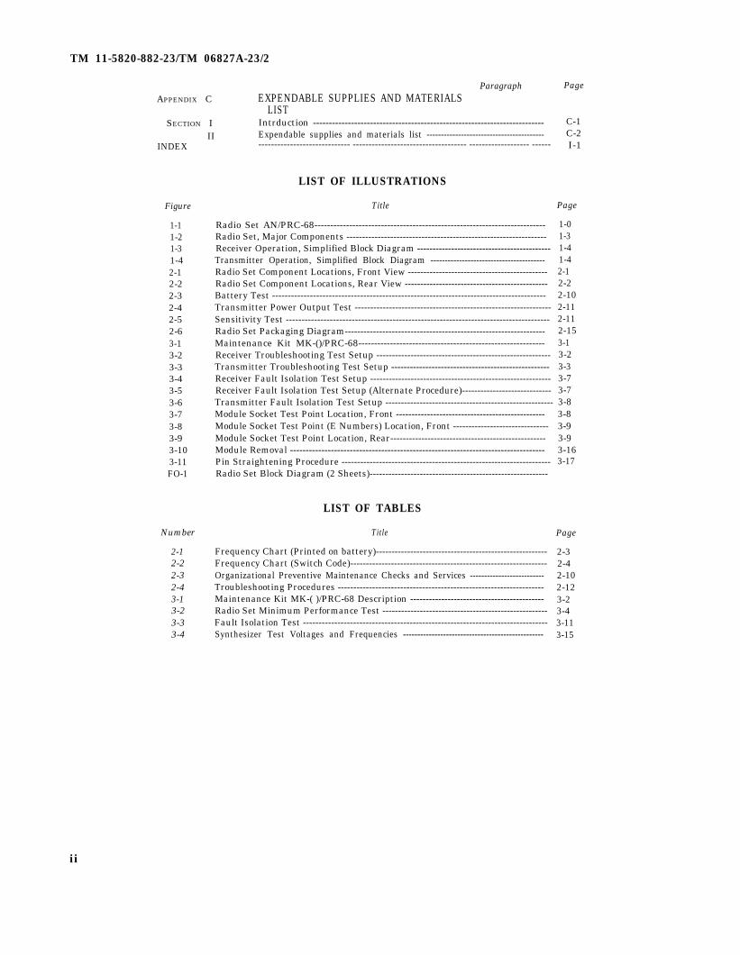
ParagraphEXPENDABLE SUPPLIES AND MATERIALS
LISTIntrduction -------------------------------------------------------------------------Expendable supplies and materials list -----------------------------------------II----------------------------- ------------------------------------ ------------------- ------
LIST OF ILLUSTRATIONS
Title
Radio Set AN/PRC-68-------------------------------------------------------------------------Radio Set, Major Components ----------------------------------------------------------------Receiver Operation, Simplified Block Diagram -------------------------------------------Transmitter Operation, Simplified Block Diagram ----------------------------------------Radio Set Component Locations, Front View ---------------------------------------------Radio Set Component Locations, Rear View ----------------------------------------------Battery Test ---------------------------------------------------------------------------------------Transmitter Power Output Test ---------------------------------------------------------------Sensitivity Test ------------------------------------------------------------------------------------Radio Set Packaging Diagram----------------------------------------------------------------Maintenance Kit MK-()/PRC-68-----------------------------------------------------------Receiver Troubleshooting Test Setup --------------------------------------------------------Transmitter Troubleshooting Test Setup ---------------------------------------------------Receiver Fault Isolation Test Setup ----------------------------------------------------------Receiver Fault Isolation Test Setup (Alternate Procedure)-----------------------------Transmitter Fault Isolation Test Setup ------------------------------------------------------Module Socket Test Point Location, Front ------------------------------------------------Module Socket Test Point (E Numbers) Location, Front -------------------------------Module Socket Test Point Location, Rear--------------------------------------------------Module Removal ---------------------------------------------------------------------------------Pin Straightening Procedure -------------------------------------------------------------------Radio Set Block Diagram (2 Sheets)---------------------------------------------------------
LIST OF TABLES
Title
Frequency Chart (Printed on battery)-------------------------------------------------------Frequency Chart (Switch Code)---------------------------------------------------------------Organizational Preventive Maintenance Checks and Services --------------------------Troubleshooting Procedures ------------------------------------------------------------------Maintenance Kit MK-( )/PRC-68 Description -------------------------------------------Radio Set Minimum Performance Test -----------------------------------------------------Fault Isolation Test ------------------------------------------------------------------------------Synthesizer Test Voltages and Frequencies -------------------------------------------------
Page
C-1C-2I-1
Page
1-01-31-41-42-12-22-102-112-112-153-13-23-33-73-73-83-83-93-93-163-17
Page
2-32-42-102-123-23-43-113-15
ii
TM 11-5820-882-23/TM 06827A-23/2
HOW TO USE THIS MANUAL
● Army maintenance levels and related Marine Corps maintenance levels are asfollows:
Operator/Crew Echelon 1 MaintenanceOrganizational Echelon 2 MaintenanceDirect Support Echelon 3 MaintenanceGeneral Support Echelon 4 MaintenanceDepot Echelon 5 Maintenance
● This manual contains all the necessary information to service Radio Set AN/PRC-68 at the organizational (echelon 2) and direct (echelon 3) supportmaintenance levels.
● Use the MAC (located in Appx. B) to determine the proper maintenance levels.● To service Radio Set AN/PRC-68 at organizational (echelon 2) maintenance
level, consult chapters 1 and 2.● To service Radio Set AN/PRC-68 at direct support (echelon 3) maintenance
level, consult chapters 1 and 3.
0-1

TM 11-5820-882-23/TM 06827A-23/2
Figure 1-1. Radio Set AN/PRC-68.
1-0

TM11-5820-882-23/TM 06827A-23/2
CHAPTER 1INTRODUCTION
Section I. GENERAL INFORMATION
1-1. ScopeThis manual describes Radio Set AN/PRC-68 (fig. 1-1)and provides instructions for organizational and directsupport maintenance. Maintenance allocation chart(MAC) is included in appendix B.
1-2. Maintenance Forms, Records, andReportsDepartment of the Army forms and procedures used forequipment maintenance will be those prescribed by TM38-750. The Army Maintenance Management System.Marine Corps units should refer to the current editionof TM 4700-15/1.
1-3. Destruction of Army Materiel to Pre-vent Enemy UseDemolition and destruction of electronic equipment willbe under the direction of the commander and in accor-dance with TM 750-244-2.
Section II. EQUIPMENT
1-6. Equipment Characteristics, Capa-bilities, and FeaturesRadio Set AN/PRC-68 (radio set) is a hand-heldreceiver-transmitter that provides ground-to-groundvoice communications in the 30 megahertz (MHz) to 79.95 MHz band. The unit is capable of secure speechoperation when it is used with the secure voice module(svm). The radio set can be used with a short or longantenna, with a standard military handset such as H-138/U, H-189/U or H-250/U, or with its built-in speak-er-microphone.
1-8. Equipment Data
1-4. Preparation for Storage or ShipmentRefer to Chapter 2, section VI for administrativestorage instructions.
1-5. Reporting Equipment ImprovementRecommendations (EIR)EIR can and must be submitted by anyone who is awareof an unsatisfactory condition with the equipmentdesign or use. It is not necessary to show a new design orlist a better way to perform a procedure, just simply tellwhy the design is unfavorable or why a procedure is dif-ficult. EIR maybe submitted on standard Form (SF) 368(Quality Deficiency Report). Mail directly to Comman-er, US Army Communications - ElectronicsComnand, ATTN: DRSEL-ME- MQ, FortMonmouth, NJ 07703. Marine Corps units mail to Com-manding Gereral, Marine Corps Logistics Base (P840),Albany, GA 31704. A reply will be furnished to you.
DESCRIPTION AND DATA
1-7. Location and Description of MajorComponentsFigure 1-2 shows the major components of the radioset. The unit consists of: the rt unit, which contains theeight modules and all necessary operating controls andconnectors; the module cover, held by two captivescrews to the chassis frame, which also holds the fre-quency changing and alignment tool; the battery, whichsnaps onto mating connectors on chassis frame; the bat-tery case, held on by two latches; and the short antenna.
GENERAL
Frequency -------------------------------------------------30.00 MHz—79.95 Long antenna ------------------------------------------ 1 mile ( 1.6 Kilo-MHz meters)
Available channels--------------------------------------1000 Operating temperature range ------------------------- - 40°F to + 159°FChannel spacing -----------------------------------------50 kHz (-40°C to +Preset channels-------------------------------------------10 65°C)Preset channel spacing----------------------------------200 kHz Weight (including battery and antenna,Modulation ------------------------------------------ frequency modula- no headset)---------------------------------------------- 40oz. (1.30 kg)
tion (fro) Size . . . . . . . . . . . . . . . . . . . . . . . . . . . . . . . . .. . . . . . . . 8.35 in (212.0 mm)
Range x 3.80 in (96.0Short antenna -----------------------------------------330 yards (300 m m )
meters) x 1.52 in (38.6mm)
Change 1 1-1

TM 11-5820-882-23/TM 06827A-23/2
Frequency stability -------------------------------------- ± 0.005 percentSpurious and harmonics radiation--------. ----------50 dB below rf car-
rier levelModulation limiting ------------------------------------- ± 15 kHz deviation
(maximum)Squelch tone (2.5—3.5 kHz deviation) -------------- 148 to 152 Hz
RECEIVER
Adjacent channel rejection ---------------------------- – 60 dBImage rejection ------------------------------------------- – 40 dB
● SINAD = Signal + Noise + Distortion
Noise + Distortion
Sensitivity- . . . . . . . . . . . .. . . .0.5 uV for 10 dB
SINAD*Squelch sensitivity ---------------------------------------0.5 uVSelectivity: 6 dB down------------------------------bandwidth greater
than ± 15 kHz60 dB down------------------------------bandwidth less than
± 50 kHzResponse to spurious signals -------------------------- – 60 dBFrequency stability -------------------------------------- ± 0.005 percentAudio output ---------------------------------------------less than 10 percent
distortion at 20m W
Section III. PRINCIPLES OF OPERATION
1-9. General InformationThe radio set contains eight plug-in modules which pro-vide all the circuitry necessary for receive and transmitoperation. These operations can be broken down intotwo basic functions, described below.
1-10. Receiver Opration (fig. 1-3)When the radio set is turned on (PWR OFF/ON/SQUELCH DIS switch in the ON position), the unit isin the receive mode (squelch is on, no receiver noise pre-sent). Signals entering the antenna are routed throughthe antenna coupler to the converter stage. The frequen-cy synthesizer and voltage controlled oscillator (vco)provide a mixer frequency for the coverter stage. Thismixer signal is determined by the setting of the frequen-cy select switches (three located on the synthesizermodule and one located on the top panel of the radioset). After the incoming signal is converted to a 12.0MHz signal, it is routed to the filter/i-f module foramplification and a second conversion to 6.5 MHz andthen to the i-f/a-f module. The intermediate frequencyand audio frequency (i-f/a-f) module detects andamplifies the signal and connects it to the built-inspeaker/microphone or external handset.
1-11. Transmitter Operation (fig.1-4)
When the radio set is in the transmit mode (unit turnedon and PUSH TO TALK switch depressed), the speaker/microphone is used as a microphone to apply a voicesignal to the modulator/mixer. Here the signal is fre-quency modulated on a carrier singal determined by thesynthesizer and voltage controlled oscillator (controlledby the frequency select switches). The output of themodulator/mixer goes to the transmitter module whereit is amplified to 1 watt minimum. The antenna couplermatches the transmitter circuit impedance to the anten-na (long or short) for maximum power transfer.
1-12. Secure Voice OperationSecure voice operation may be utilized on the radio setby connecting the secure voice module (svm) to the bot-tom of the rt unit. The battery case and battery must beremoved first. The svm connector (located next to thebattery connector) has a small black shorting plug in-stalled. This plug must be removed to install the svm inits place. If the radio set is not being used with securevoice equipment, the shorting plug must be installed inthe svm connector for normal set operation. The re-tainer (attached to SVM plug) must be wrapped aroundthe connector before installation of plug to preventdamage to retainer line.
1-2

TM 11-5820-882-23/TM 06827A-23/2
Figure 1-2. Radio set, major components.1-3

TM 11-5820-882-23/TM 06827A-23/2
Figure 1-3. Receiver operation, simplified block diagram.
Figure 1-4. Transmitter operation simplified, block diagram.
1 - 4

TM 11-5820-882-23/TM 06827A-23/2
CHAPTER 2ORGANIZATIONAL MAINTENANCE
Section I REPAIR PARTS, SPECIAL TOOLS, TMDE, AND SUPPORT EQUIPMENT2-1. Common Tools and Equipment for tools and equipment to be used at the organizationalFor authorized common tools and equipment refer to maintenance level. Refer to applicable T/F (table ofthe Modified Table of Organization and Equipment equipment) for Marine Corps units.
(MTOE) applicable to your unit. 2-3. Repair Parts2-2. Special Tools, TMDE, and Support Repair parts are listed in the Repair Parts and Special
Equipment Tools List (TM 11-5820-882-23P) covering organiza-tional and direct support maintenance for this equip-
Refer to the maintenance allocation chart (Appx. B), ment.
Figure 2-1. Radio set component locations, front view.2-1

TM 11-5820-882-23/TM 06827A-23/2
Section II. SERVICE UPON RECEIPT2-4. Checking Unpacked Equipment
a. Inspect the equipment for damage incurred dur-ing shipment. If the equipment has been damaged,report the damage on DD Form 6, Packaging Improve-ment Report.
b. Check the equipment against the packing slip tosee if the shipment is complete. Report all discrepanciesin accordance with the instructions of TM 38-750.Marine Corps units should refer to current edition ofTM 4700-15/1.
c. Check DA PAM 310-7 to see whether there areany modification work orders pertaining to this equip-ment.
2-5. Disassembly InstructionsTo disassemble the radio set for battery replacement orchannel changing and alignment (fig, 1-2), perform thefollowing:
a. Unfasten latches on battery case and remove bat-tery case. (Handle case carefully as damaged case willnot seal properly).
b. Remove battery by disconnecting snap ter-
minals.c. Remove module cover by turning the two captive
screws counterclockwise (located on bottom of modulecover).
NOTEMake sure that the svm shorting plug (locatednext to the battery terminal connector in the rtunit, fig. 2–2), is installed and in good condi-tion. The radio set will not work unless theshorting plug or svm is installed.
2-6. Reassembly InstructionsTo reassemble the radio set, perform the following:
a. Apply a thin coat of silicone grease (NSN 6850-00-177-5094) to top edge of the module cover. Slidemodule cover over rt unit and secure with the two cap-tive screws located on the bottom of the cover (turnclockwise),
b. Attach battery to battery connector on rt unit,c. Apply a thin coat of silicone grease to the top edge
of the battery case and attach battery case and securewith the two latches,
Figure 2-2. Radio set component locations, rear view.
2-2

2-7. Frequency Changing and Align-ment Procedures.The ten position (0 through 9) CHAN switch on thefront panel provides ten preset sequential channels spac-ed 200 kHz apart over a 2 MHz bandwidth. Any portionof the 30.00 MHz to 79.95 MHz range can be selected bychanging the three switches (A, B, and D) on the syn-thesizer module and the CHAN switch on the top panelof the radio set. (Refer to table 2-1 or table 2-2 for fre-quencies and their respective switch settings). Wheneverthe frequency of a radio set is changed (excluding theten preset channels), the transmitter module and anten-na coupler module must be realigned to ensure propermatching and maximum power transfer of the radio setto the antenna.
a. Changing Frequency. To change the frequencyof the radio set, perform the following:
(1) Disassemble unit (para 2-5).(2) refer to figure 2-2. Set synthesizer switches,
with the enclosed alignment tool (or JFD 5284 align-ment tool), and the top panel CHAN switch, to the newfrequency using table 2-1 or table 2-2, as applicable.
NOTE
The frequency chart shown in table 2-1 isprinted on the battery. Table 2-2 is a completelisting of all frequencies including degraded(low sensitivity) channels.
(3) Set the transmitter switch and antenna couplerswitch (fig. 2–1) with the enclosed alignment tool to thesame position as switch A on the synthesizer module.
(4) Connect battery.b. Alignment. After the frequency of the radio set
has been changed, perform the following procedures forradio set alignment (fig. 2-1 ):
(1) Install antenna (either short or long).(2) Set CHAN switch to 5.(3) Preset Cl on the transmitter module fully
clockwise (use enclosed alignment tool of JFD 5284).(4) Set PWR OFF/ON/SQUELCH DIS switch to
ON.(5) Press push-to-tune switch (on side of radio
set) and adjust VOL control for comfortable level.(6) Using the alignment tool, adjust C1 on the
transmitter module counterclockwise for the lowesttone.
(7) Release push-to-tune switch.(8) The antenna coupler adjustment (L1) must be
made using Test Set TS–3354/PRC-68 (test set),(a) Remove cover from test set.(b) Install test set antenna.(c) Set FUNCTION switch to FSM position.
(9) Hold radio set so the antenna is approximately6 to 24 inches from FSM antenna on test set.
(10) Press PUST TO TALK switch on radio setand use alignment tool to adjust L1 (located on antenna
coupler) for maximum (peak) indication on the test Setmeter.
(11) Release PUSH TO TALK switch.(12) With alignment tool, adjust squelch (SQ
ADJ) control on i-f/a-f module counterclockwise untilnoise is heard.
(13) Slowly turn SQ ADJ control clockwise untilreceiver quiets, then advance control one full turnclockwise.
(14) Return CHAN switch to channel originallyselected.
(15) Set PWR OFF/ON/SQUELCH DIS switchto PWR OFF.
(16) Remove battery.(17) Reinstall alignment tool on module cover.(18) Reassemble unit (para 2-6).
c. Frequency Chart (Battery). To use the chart intable 2-1, select the frequency value for each synthesizerswitch in turn, that comes closest to (but not over) thedesired frequency. Then add the values of the switches(A, B, CHAN (C), and D) to determine the operatingfrequency. By using the proper combination, any fre-quency between 30.00 to 79.95 MHz (in 50 MHz steps)may be selected.
Table 2-1. Frequency Chart (Printed on Battery)
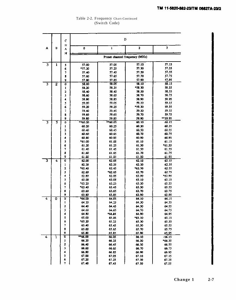
d. Frequency Chart (Switch Code). The fol lowingcharts in table 2 -2 may be used to determine anoperating frequency from the synthesizer switch codesor the synthesizer switch codes from a known frequen-cy. (Each chart covers a 2 MHz band). To find the
Change 1 2-3

TM 11-5820-882-23/TM 06827A-23/2
operating frequency (in MHz) from the switch codes,find the numbers that correspond to the A, B, CHAN
and D positions.
Example: Switch code is 3412, where:A = 3B = 4
CHAN = 1D = 2
(1) Find the chart which has A = 3 and B = 4 atthe top left hand corner.
(2) Next locate 1 in the CHAN column.
(3) Read across until you come to the frequencynumber under the 2 in the D column.
(4) Answer should be 62.30 MHz.
To find the synthesizer switch codes when thefrequency (in MHz) is known, find the frequency in the
chart and read off the A, B, CHAN, and D switch
codes.
Example: Frequency is 53.15 MHz
(1) Find the chart which contains the fre-quency.
(2) Read the upper left hand comer codes (A,B,) first (2, 6).
(3) Go to the CHAN column and locate thenumber that corresponds to frequency (5).
(4) Read the number in the D column that cor-responds to the frequency (3).
(5) The synthesizer switch code is 2653.
Table 2-2. Frequency Chart(Switch Code)
2-4 Change 1● See Notes at foot of table.

TM 11-5820-882-23/TM 06827A-23/2
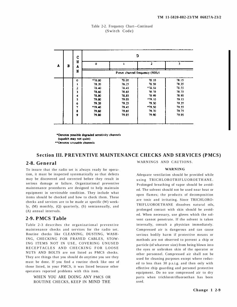
Table 2-2. Frequency Chart—Continued(Switch Code)
Change 1 2-5

TM 5820-882-23/TM 06827A-23/2
Table 2-2. Frequency Chart—Continued(Switch Code)
2-6 Change 1
TM 11-5820-882-23/TM 06827A-23/2
Table 2-2. Frequency Chart-Continued
(Switch Code)
Change 1 2-7

TM 11-5820-882-23/TM 06827A-23/2
Table 2-2. Frequency Chart—Continued(Switch Code)
2-8 Change 1
TM 11-5820-882-23/TM 06827A-23/2
Table 2-2. Frequency Chart—Continued(Switch Code)
Section III. PREVENTIVE MAINTENANCE CHECKS AND SERVICES (PMCS)
2-8. GeneralTo insure that the radio set is always ready for opera-tion, it must be inspected systematically so that defectsmay be discovered and corrected before they result inserious damage or failure. Organizational preventivemaintenance procedures are designed to help maintainequipment in serviceable condition. They include whatitems should be checked and how to check them. Thesechecks and services are to be made at specific (W) week-ly, (M) monthly, (Q) quarterly, (S) semiannually, and(A) annual intervals.
2-9. PMCS TableTable 2-3 describes the organizational preventivemaintenance checks and services for the radio set.Routine checks like CLEANING, DUSTING, WASH-ING, CHECKING FOR FRAYED CABLES, STOW-ING ITEMS NOT IN USE, COVERING UNUSEDRECEPTACLES AND CHECKING FOR LOOSENUTS AND BOLTS are not listed as PMCS checks.They are things that you should do anytime you see theymust be done. If you find a routine check like one ofthose listed, in your PMCS, it was listed because otheroperators reported problems with this item.
WHEN YOU ARE DOING ANY PMCS ORROUTINE CHECKS, KEEP IN MIND THE
WARNINGS AND CAUTIONS.
WARNING
Adequate ventilation should be provided whileusing TRICHLOROTRIFLUOROETHANE.Prolonged breathing of vapor should be avoid-ed. The solvent should not be used near heat oropen flames; the products of decompositionare toxic and irritating. Since TRICHLORO-TRIFLUOROETHANE dissolves natural oils,prolonged contact with skin should be avoid-ed. When necessary, use gloves which the sol-vent cannot penetrate. If the solvent is takeninternally, consult a physician immediately.Compressed air is dangerous and can causeserious bodily harm if protective means ormethods are not observed to prevent a chip orparticle (of whatever size) from being blown intothe eyes or unbroken skin of the operator orother personnel. Compressed air shall not beused for cleaning purposes except where reduc-ed to less than 30 p.s.i.g. and then only witheffective chip guarding and personel protectiveequipment. Do no use compressed air to dryparts when trichlorotrifluoroethan has beenused.
Change 1 2-9
TM 11-5820-882-23/TM 06827A-23/2
Table 2-3. Organizational Preventive Maintenance Checks and Services
Section IV. TROUBLESHOOTING2-10. Visual Inspection malfunction is still not located, higher level trouble-
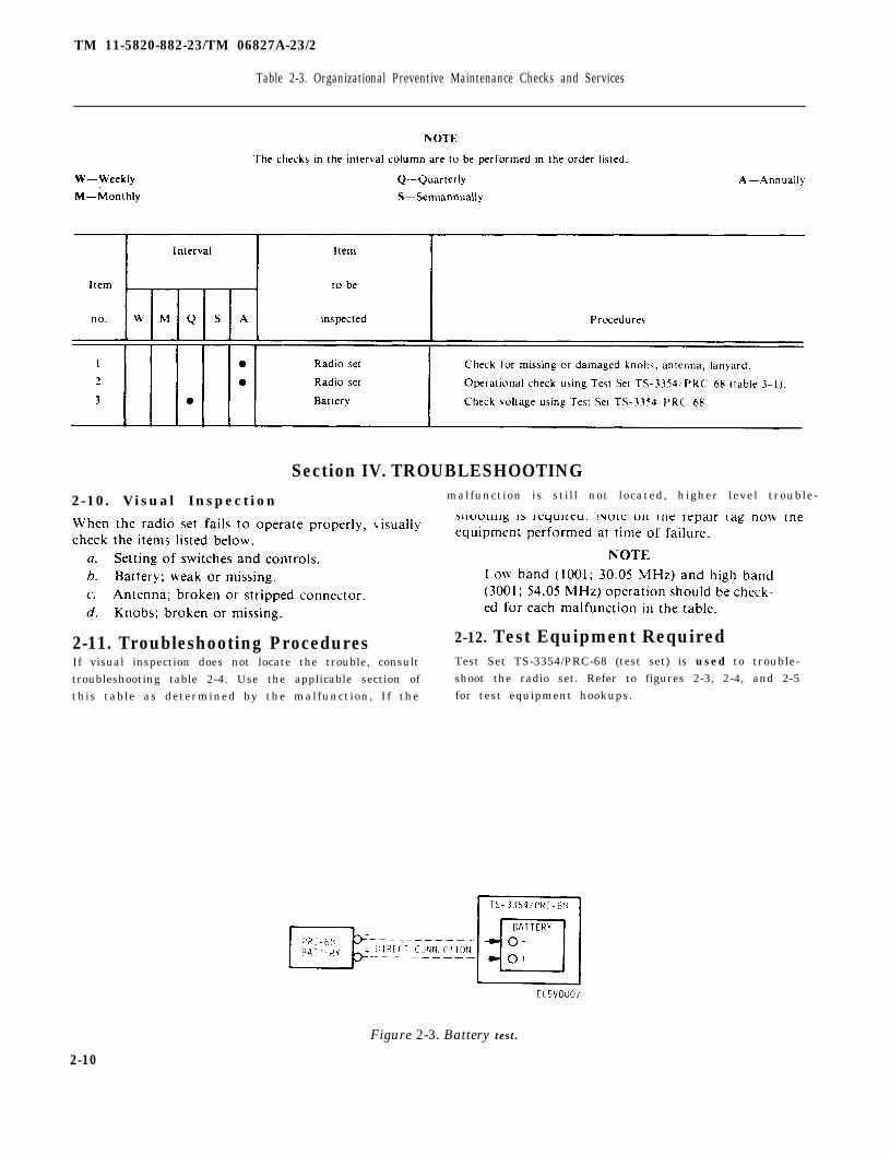
2-11. Troubleshooting Procedures 2-12. Test Equipment RequiredIf visual inspection does not locate the trouble, consult Test Set TS-3354/PRC-68 (test set) is used to trouble-
troubleshooting table 2-4. Use the applicable section of shoot the radio set. Refer to figures 2-3, 2-4, and 2-5
this table as determined by the malfunction, If the for test equipment hookups.
Figure 2-3. Battery test.
2-10

TM 11-5820-882-23/TM 06827A-23/2
Figure 2-4. Transmitter power output test.
Figure 2-5. Sensitivity test.
2-11

2-12
para 2-18
para 2-17
paragraph 2-7
para 2-7
para 2-5
figure 2-5
para 2-7
fig. 2-1
para 2-6
para 2-7
fig 2-1
para 2-7
figure 2-4
para 2-5
fig. 2-2
fig. 2-3
TM 11-5820-882-23/TM 06827A-23/2
Table 2-4. Troubleshooting Procedures
para 2-6para 2-7
TM 11-5820-882-23/TM 06827A-23/2
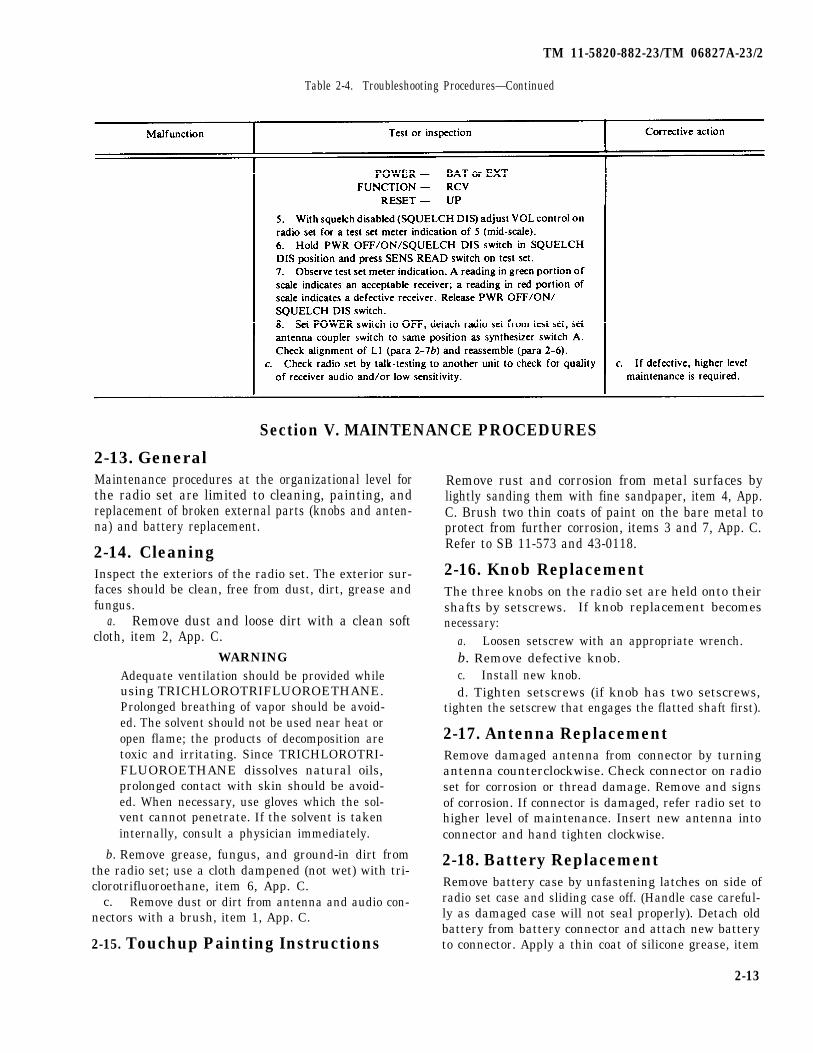
Table 2-4. Troubleshooting Procedures—Continued
Section V. MAINTENANCE PROCEDURES
2-13. GeneralMaintenance procedures at the organizational level for Remove rust and corrosion from metal surfaces bythe radio set are limited to cleaning, painting, andreplacement of broken external parts (knobs and anten-na) and battery replacement.
2-14. CleaningInspect the exteriors of the radio set. The exterior sur-faces should be clean, free from dust, dirt, grease andfungus.
a. Remove dust and loose dirt with a clean softcloth, item 2, App. C.
WARNINGAdequate ventilation should be provided whileusing TRICHLOROTRIFLUOROETHANE.Prolonged breathing of vapor should be avoid-ed. The solvent should not be used near heat oropen flame; the products of decomposition aretoxic and irritating. Since TRICHLOROTRI-FLUOROETHANE dissolves natural oils,prolonged contact with skin should be avoid-ed. When necessary, use gloves which the sol-vent cannot penetrate. If the solvent is takeninternally, consult a physician immediately.
b. Remove grease, fungus, and ground-in dirt fromthe radio set; use a cloth dampened (not wet) with tri-clorotrifluoroethane, item 6, App. C.
c. Remove dust or dirt from antenna and audio con-nectors with a brush, item 1, App. C.
2-15. Touchup Painting Instructions
lightly sanding them with fine sandpaper, item 4, App.C. Brush two thin coats of paint on the bare metal toprotect from further corrosion, items 3 and 7, App. C.Refer to SB 11-573 and 43-0118.
2-16. Knob ReplacementThe three knobs on the radio set are held onto theirshafts by setscrews. If knob replacement becomesnecessary:
a. Loosen setscrew with an appropriate wrench.b. Remove defective knob.c. Install new knob.d. Tighten setscrews (if knob has two setscrews,
tighten the setscrew that engages the flatted shaft first).
2-17. Antenna ReplacementRemove damaged antenna from connector by turningantenna counterclockwise. Check connector on radioset for corrosion or thread damage. Remove and signsof corrosion. If connector is damaged, refer radio set tohigher level of maintenance. Insert new antenna intoconnector and hand tighten clockwise.
2-18. Battery ReplacementRemove battery case by unfastening latches on side ofradio set case and sliding case off. (Handle case careful-ly as damaged case will not seal properly). Detach oldbattery from battery connector and attach new batteryto connector. Apply a thin coat of silicone grease, item
2-13

TM 11-5820-882-23/TM 06827A-23/2
5, App. C, to the top edge of the battery case (to In order to prevent water seepage make surefacilitate “O” ring sealing). Reinstall battery case and battery case and rubber gasket are not damag-fasten latches. ed. Make sure battery case and module cover
CAUTION are properly aligned before fastening latches.
Section VI. PREPARATION FOR STORAGE OR SHIPMENT2-19. Packaging, Marking and Shipping can be readied for mission performance within 24
Requirements hours. Before placing an item in administrative storage,the next scheduled preventive maintenance checks and
Refer to figure 2-6 for packaging diagram. services should be performed, all known deficiencies
2-20. Type of Storage corrected, and all current modification work orders ap-
Short term (administrative storage) = 1 to 45 days. Ad-plied. The administrative storage site should provide re-quired protection from the elements and allow access
ministrative storage covers storage of equipment which for visual inspection and exercising when applicable.
2-14

TM 11-5820-882-23/TM 06827A-23/2
Figure 2-6. Radio set packaging diagram.
2-15


TM 11-5820-882-23/TM 06827A-23/2
CHAPTER 3DIRECT SUPPORT MAINTENANCE INSTRUCTIONS
Section I. REPAIR PARTS, SPECIAL TOOLS, TMDE, AND SUPPORT EQUIPMENT
3-1. Common Tools and Equipment tools and equipment to be used at direct supportFor authorized common tools and equipment refer to maintenance level.the Modified table of Organization and Equipment 3-3. Maintenance Kit(MTOE) applicable to your unit.
Figure 3-1 shows Maintenance Kit MK-( ) /PRC-68 us-3-2. Special Tools, TMDE, and Support ed with the test equipment to troubleshoot the radio set.Equipment Table 3-1 provides a brief description of the contents of
Refer to the maintenance allocation chart (App. B), for the kit.
Figure 3-1. Maintenance Kit MK-( )/PRC-68.3-1
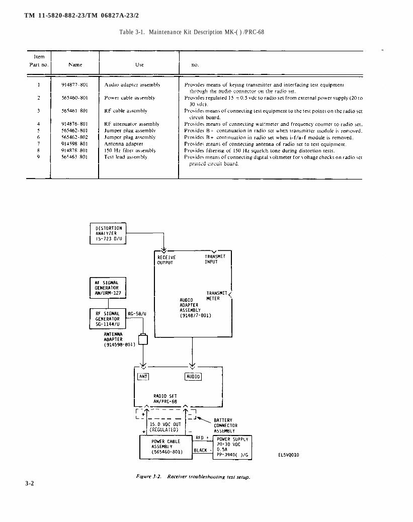
Figure 3-2. Receiver troubleshooting test setup.
TM 11-5820-882-23/TM 06827A-23/2
Table 3-1. Maintenance Kit Description MK-( ) /PRC-68
3-2
TM 11-5820-882-23/TM 06827A-23/2
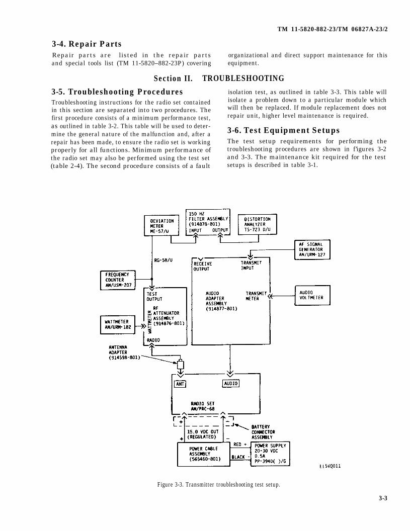
3-4. Repair PartsRepair parts are listed in the repair parts organizational and direct support maintenance for thisand special tools list (TM 11-5820–882-23P) covering equipment.
Section II. TROUBLESHOOTING
3-5. Troubleshooting Procedures isolation test, as outlined in table 3-3. This table will
Troubleshooting instructions for the radio set contained isolate a problem down to a particular module which
in this section are separated into two procedures. The will then be replaced. If module replacement does not
first procedure consists of a minimum performance test, repair unit, higher level maintenance is required.
as outlined in table 3-2. This table will be used to deter- 3-6. Test Equipment Setupsmine the general nature of the malfunction and, after arepair has been made, to ensure the radio set is working The test setup requirements for performing theproperly for all functions. Minimum performance of troubleshooting procedures are shown in f’igures 3-2the radio set may also be performed using the test set and 3-3. The maintenance kit required for the test(table 2-4). The second procedure consists of a fault setups is described in table 3-1.
Figure 3-3. Transmitter troubleshooting test setup.
3-3

figure 3-2
TM 11-5820-882-23/TM 06827A-23/2
Table 3-2. Radio Set Minimum Performance Test
Table 3-3, steps 1 through 11
Table 3-3, steps 1 through 11.
Table 3-3, steps 1 through 11.
Table 3-3, steps 1 through 11.
Table 3-3, steps 1 through 11.
3-4

figure 3-3
figure 3-3
TM 11-5820-882-23/TM 06827A-23/2
Table 3-2. Radio Set Minimum Performance Test—Continued
Table 3-3, steps 12 through 21.
Table 3-3, steps 12 through 21.
Table 3-3,steps 12 through 21.
Table 3-3, steps 12 through 21.
Table 3-3, steps 12 through 21.
Table 3-3, steps 12 through 21.
Table 3-3, steps 2 through 21.
3-5

TM 11-5820-882-23/TM 06827A-23/2
Table 3-3, steps 12 through 21.
Table 3-2. Radio Set Minimum Performance Test—Continued
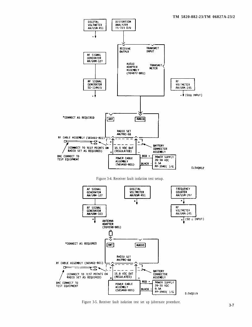
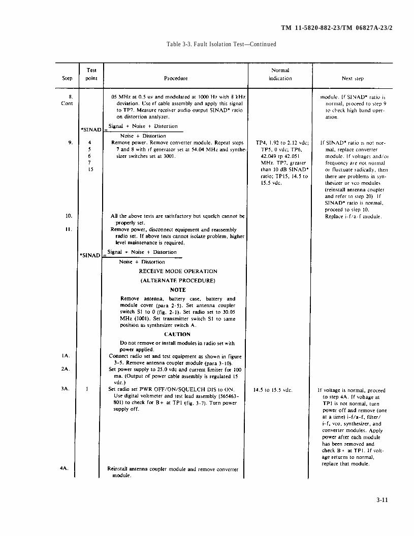
3-7. Fault Isotation TestTable 3-3 is a fault isotation test for the radio set. By us-ing these tests and the associated test equipment, theradio set may be fault isolated to a defective module. Ifthe problem cannot be located to a defective module orother DS level maintenance, then higher level mainte-nance is required. In all cases, after a defective modulehas been replaced or a repair made to the radio set, theminimum performance test (table 3–2), or minimum per-formance check using the test set (table 2-4), must beperformed to ensure the radio set is fully operational.
3-8. Fault Isolation Test Equipment Set-ups
Figure 3-4 and 3-6 show the equipment setups necessaryto perform the fault isolation tests.
3-9. Test Point LocationsFigures 3-7 and 3-8 show the test point locations used infault isolation testing. Test point connections are madeby a special rf cable assembly 565461-801 (part of Main-tenance Kit MK-( ) /PRC-68). In all cases where thiscable is used, the center conductor is connected to thetest point called for, and the shield is connected to thenearest ground point on the printed circuit board. TheBNC connector end mates with the applicable testequipment unit, when called for.
3-6
TM 5820-882-23/TM 06827A-23/2
Figure 3-4. Receiver fault isolation test setup.
Figure 3-5. Receiver fault isolation test set up (alternate procedure.3-7

TM 11-5820-882-23/TM 06827A-23/2
3-8
Figure 3-6. Transmitter fault isolation test setup.
Figure 3-7. Module socket test point location, front.

TM 11-5820-882-23/TM 06827A-23/2
Figure 3-8. Module socket test point (E numbers) location, front.
Figure 3-9. Module socket test point location, rear.
3-9

Table 3-3. Fault Isolation Test
3-10
table 3-3
figures 3-5 and 3-8
para 2-5
fig. 2-1
figure 3-4 para 3-10
fig. 3-7
TM 11-5820-882-23/TM 06827A-23/2
para 2-5
fig. 2-1
para 3-10
fig. 3-7
TM 11-5820-882-23/TM 06827A-23/2
Table 3-3. Fault Isolation Test—Continued
3-11

3-12
fig. 3-8
fig. 3-8
figure 3-8
fig. 3-8
para 2-5
fig. 2-1
TM 11-5820-882-23/TM 06827A-23/2
Table 3-3. Fault Isolation Test—Continued

figure 3-6
para 3-10
fig. 3-7
table 3-4
TM 11-5820-882-23/TM 06827A-23/2
Table 3-3. Fault Isolation Test—Continued
3-13

para 2-5
para 3-10
table 3-4
table 3-4
table 3-4
TM 11-5820-882-23/TM 06827A-23/2
Table 3-3. Fault Isolation Test—Continued
3-14

TM 11-5820-882-23/TM 06827A-23/2
Table 3-3. Fault Isolation Test—Continued
Table 3-4. Synthesizer Test Voltages and Frequencies
Section III. MAINTENANCE PROCEDURES
3-10. Removal and Replacement of (2) Inset corner of screwdriver tip into forwardModules
.
The following procedures are used for removal and in-sertion of the modules in the Radio Set. The Special in-structions in paragraph 3-11 should also be observed toprevent secondary damage and failures, Refer toparagraph 2-5 for disassembly instructions.
a. Converter Module.(1) Hold radio in left hand with control panel
toward palm, thumb over converter module and fingersover radio on opposite side.
(panel end) pry slot on converter module. Extend leftthumb over converter module to stop module travel andpry up this end of the module (see fig. 3-10). Movescrewdriver to other slot on the converter module andpry up. Remove module from radio with fingers.
(3) To insert converter module, align module pinswith frame sockets and gently press module into place,
b. I-f/A-f Module.(1) Hold radio in left hand with bottom side (bat-
tery connector side) in palm and left thumb over i- f/a-fmodule and fingers on back side of radio.
Change 1 3-15

TM 11-5820-882-23/TM 06827A-23/2
(2) Insert screwdriver into side slot nearest bot-tom side (battery side) of radio and pry up module usingthe left thumb to restrict travel. Move screwdriver to themiddle slot on i–f/a–f module and pry up. Removemodule with fingers by using slight side to side rockingmotion of module.
(3) To inset i-f/a-f module, align module pinswith frame sockets and gently push module into place.
c. Filter/ I-F Module.(1) First remove the i-f/a-f module.(2) Hold radio in left hand with bottom side (bat-
tery connector side) in palm and left thumb over anten-na coupler module (rear part of thumb should be overthe filter/i-f module). Carefully pry up the i-f/a-f endof the filter/i-f module with the screwdriver. Then pryup the opposite end of filter/i–f module and removemodule with your fingers.
(3) To insert filter/i-f module, align module pinswith frame sockets and gently push module into place.
d. Transmitter Module.(1) First remove the i-f/a-f and converter
modules.(2) Hold radio in left hand with transmitter
module facing up. Remove module with right thumband forefinger on ends. Use a top (panel) -to-bottomrocking motion to loosen the module in the framesockets.
(3) To insert the module, align module pins withframe sockets and gently push module into place.
e. Antenna Coupler Module.(1) First remove i-f/a-f and converter modules.(2) Hold the radio in left hand with antenna
coupler module facing up. Remove module with rightthumb and forefinger on the ends. Use a top (panel) -to-bottom rocking motion to loosen the module in thesockets.
(3) To insert antenna coupler module, alignmodule pins with frame sockets and gently push
module into place.f. Vco, Modulator MixerJ and Synthesizer
Modules.(1) Hold radio in left hand with modules facing
up. Insert screwdriver into slots in frame and gently pryup the removable circuit board with the three modulesattached.
modules from frame sockets and pull it away from theradio panel to expose the CHAN switch cable connec-tor. Pull removable circuit board far enough away frompanel (approximately 3/4 inch) to grip the cable connec-tor with the thumb and forefinger of the left hand; thenunplug the connector by gently pulling away with theremovable circuit board assembly.
(3) The three modules may be removed now bypulling them up from the removable circuit board withthe fingers.
(4) To insert the vco, modulator/mixer, or syn-thesizer module, align the module pins with the socketson the removable circuit board. Gently push the moduleinto place. When all three modules are installed on theremovable circuit board, connect the synthesizer cableassembly. Align the removable circuit board pins withthe frame sockets and gently push the removable circuitboard into place. Make sure the modules and removablecircuit board are properly seated.
3-11. Special Instructionsa. Always inspect a module for bent or broken pins
before inserting it into the frame sockets. To straightenbent pins, use needle-nose or long-nose pliers withsmooth jaws. Position the jaws so that the whole pin isstraightened simultaneously (see fig. 3-11 ).
b. When inspecting for bent pins, the pins shouldappear to be reasonably vertical in relation to themodule bottom surface. Bent pins usually result whenexcessive prying force is applied to only one end or sideof a module. The thumb of the opposite hand should
Figure 3-10. Module removal.
3-16

always be used to stop the module travel and oppose theprying force.
c. Always inspect frame sockets for damage beforeinserting a module. .4 normal socket should have fourspring leafs visible. If a spring leaf is pushed over to thewrong side of a socket, it can be pushed back into placewith a sharp pointed tool (pin, needle, scribe, etc.). Ifthe leaf breaks off or is smashed into the bottom of thesocket, the socket should be replaced if possible.However, the socket will still make good contack withthe module pin after the damaged leaf is removed fromthe socket. The radio setcan be made at a higher
3-12. Lubrication
3-14. General
is still operational until repairslevel.
TM 11-5820-882-23/TM 06827A-23/2
All sealing surfaces (module cover and battery case)should have a thin film of silicone grease (NSN 6850-00-177-5094) applied to hepl preserve watertightnessand keep the rubber seals pliable. If a handset is usedwith the radio set, a small amount of silicone greaseshould also be applied to the “O” ring in the connectorto facilitate insertion.
3-13. Placing in ServiceAfter the radio set has been repaired, the unit must bechecked out completely with the minimum performancetest (table 3-2). Upon the completion of the test, theradio set should be set to some predetermined frequencyand properly aligned before being returned to service.
Section IV. PRINCIPLES OF OPERATION3-16. Receive Operation
Radio Set AN/PRC-68 consists of eight plug-inmodules, a frame assembly, and battery assembly. Prin-ciples of operation of the radio set is limited to descrip-tion of the modules and their interfacing with eachother. Refer to figures 2-1 and 2-2 for module loca-tions.
3-15. Circuit FunctioningCircuit functioning of the radio set (fig. FO-1) can bebroken down into modules that comprise separate func-tions (receive and transmit) and modules that are usedfor both functions (synthesizer and voltage controlledoscillator). The battery saver circuitry, tone tuning, and150 Hz squelch tone signal are also discussed.
The receiver is packaged in three modules. Thesemodules are:
a. Converter Module (1A6). The convertermodule consists of two bandswitched, varactor-tuned rfamplifiers and the receiver 1st mixer which converts theoperating frequency to the first i-f of 12 MHz. The low-band rf amplifier tunes the frequency range from 30 to54 MHz while the high-band tunes 54 to 80 MHz. Thesettings of the frequency select switches (A, B, and D,on synthesizer module, and preset CHAN switch) deter-mine the operating frequency of the rf amplifier and thelocal oscillator injection frequency to the first mixer.This injection signal is provided by the voltage controll-ed oscillator (VCO) module. For the low-band (30 to 54
Figure 3-11. Pin Straightening procedure.
3-17

TM 11-5820-882-23/TM 06827A-23/2
MHz), it is 12.000 MHz above the rf input frequencies;for the high-band (54 to 80 MHz), it is 12.000 MHzbelow the rf input frequencies.
b. Filter/I-f Module (1A3). The filter/i-f modulecontains a 12 MHz crystal filter, 12 MHz i–f amplifier,18.5 MHz crystal oscillator, and a 6.5 mixer/amplifier(2nd mixer), The output of the second mixer (6.5 MHz)is the difference of the 12.0 MHz input and 18.5 MHzinput from the crystal oscillator.
c. I-f/A-f Module (1A2). The i-f/a-f modulecontains a 6.5 MHz i-f amplifier/discriminator, squelchcircuits, audio amplifier, and a low-pass filter. Otherfunctions contained within the module are a tone tunercircuit and battery saver switch. The input signal to thei–f/a-f module is the 6.5 MHz frequency modulated sig-nal from the filter/i-f module. The signal is detectedand routed through the low-pass filter to the audioamplifier. When a handset of other audio accessory isconnected to the AUDIO connector of the radio set, thespeaker mute circuit electronically switches off theaudio signal to the speaker and routes it to the handset.The squelch threshold is adjusted by a potentiometerlocated in the module. The squelch circuit is normallyon when the radio set is turned on. However, squelchcan be disabled by turning the function switch to theSQUELCH DIS position.
3-17. Transmit OperationThe transmitter is packaged in three modules. Thesemodules are:
a. Modulator/Mixer Module (1A8). The modulator/mixer module contains a speech amplifier and filter, 150Hz (squelch tone) buffer, 12 MHz deviation oscillator rfmixer, and two bandswitched, varactor-tuned rf pream-plifiers. The speech amplifier increases the level of themicrophone signal sufficiently for clipping action. Theoutput of the amplifier passes through a low-pass filterbefore it is superimposed upon a 12 MHz deviation os-cillator. The 150 Hz squelch tone from the synthesizeris also routed to the deviation oscillator after passingthrough a buffer and the speech filter network. The fre-quency modulated output of the oscillator is combinedin a varactor-tuned mixer stage with the frequency syn-thesizer output signals to create the desired rf outputfrequency. The rf output is amplified by two bandswit-ched, varactor-tuned rf preamplifiers. For frequenciesin the low-band (30 to 54 MHz), the output frequency is12.000 MHz below the synthesizer frequency; and forthe high-band (54 to 80 MHz), the output frequency is12.000 MHz above the synthesizer frequency.
b. Transmitter Module (1A4).. The transmittermodule contains an rf preamplifier, driver, final poweramplifier and low-pass band filters. The output fromthe modulator is applied to the preamplifier for ampli-
fication to approximately 1 vrms. The output of thedriver stage is approximately 100 mw. This stage has atuned circuit which tunes the output of the transmiter. Tuning is accomplished by using the built-in tone tunerand adjusting C1 on the module. The tone tuner cir-cuitry is located in the i-f/a-f module and converts thevariation in the collector currents of the transmitterstages to a tone frequency when the tone tuner button(located on the side of the frame assembly) is depressed.The final output (approximately 1.5 watts) is routedthrough one of four band-selected low-pass harmonicfilters to the antenna coupler (1A5).
c.Antenna Coupler Module (1A5). The antennacoupler module contains the rf transmit/receive diodeswitching circuits and the antenna matching circuit. Pindiodes in the module provide transmit/receive switchingfunctions to the antenna matching network. These di-odes also isolate the transmit/receive circuitry to pre-vent the transmitted signal from entering the receiver in-put. The antenna matching network provides an imped-ance match between the antenna and transmitter circuits(between 50 ohms and 100 ohms). The matching range isdetermined by the position (1 through 4) of the rotaryswitch located on the module (set the same as the Aswitch on the synthesizer). Optimum tuning is ac-complished by using the field strength meter on the testset and adjusting L1 on the coupler module (tune formaximum indication).
3-8. Frequency Synthesizer (1A7 and1A8)The radio set frequency synthesizer consists of the vcomodule (1A7) and the synthesizer module ( 1A9). Thefuncton of the frequency synthesizer is to generate therequired mixer injection frequency and tuning voltagefor the converter and modulator modules when a givenoperating frequency is selected. The frequency syn-thesizer also determines which band (low or high) is ac-tive depending upon selection of the operating frequen-cy.
a. The frequency range of the synthesizer is from42.000 MHz to 67.950 MHz which corresponds with agenerated tuning voltage range from 2.0 vdc to 11.0 vdcrespectively. The frequency synthesizer is programmablein 50 kHz steps with the frequency select (A, B. and D)switches on the synthesizer module and the CHAN (C)switch on the panel of the radio set.
b. The frequency range of the synthesizer isgenerated twice to provide low-band radio set operationfrom 30,000 MHz to 53.950 MHz (positions 1 and 2 ofthe A switch), and high-band radio set operation from54.000 MHz to 79.950 MHz (positions 3 and 4 of the A
3-18

TM 11-5820-882-23/TM 06827A-23/2
switch). The two bands are required to cover the 30 to80 MHz range of the radio set with varactor tuning.
c. The basic purpose of the frequency synthesizer isto generate the discrete channel frequencies with an ac-curacy of ±25 ppm. This is accomplished by phase lock-ing a voltage controlled oscillator (VCO) to a standardcrystal controlled reference frequency. The referencefrequency of the synthesizer is 12.5 kHz crystal oscilla-tor by a factor of 800, or dividing the output of the 12.5MHz crystal oscillator by a factor of 1000. The divisionfactor is determined by the position of the A switch. Thereference divider ( ÷ K) consists of an injection lockedoscillator which divides by 4 (10 MHz) or 5 (12.5 MHz),and a fixed divide ratio (200) digital counter. The 12.5kHz output of the reference divider is routed to thephase comparator (detector).
d. To achieve phase locking, the output of the vco(42 to 68 MHz) must be frequency translated and divid-ed douwn to 12.5 kHz for phase comparison with the 12.5 kHz reference frequency. Because the vco must pro-vide 520 discrete frequencies spaced 50 kHz apart, avariable frequency divider is required to divide each oneof these discrete frequencies down to 12.5 kHz. Thevariable divider ( ÷ N) ratio is determined (programmed)by setting the synthesizer switches to the code cor-responding with the desired operating frequency. Oncethe ÷ N ratio is programmed, the vco can phase lock on-ly at that frequency which translates down to 12.5 kHz.
e. Because the maximum counting speed of thecmos programmable divider is 5 MHz, the 42 to 68 MHzrange of the vco must be frequency translated down toless than 5 MHz. This is accomplished by first dividing
the output frequency of the vco with the ± 4 prescaler inthe vco module. The prescaler output is routed to themixer in the synthesizer module. The output of the mix-er is the difference frequency of the prescaler input andthe 10 MHz or 12.5 MHz reference oscillator.
f. Because the capture range of the phase detector isnarrow (approximately ± 500 kHz at the vco frequency),the vco must be swept over its frequency range to a fre-quency within this capture range. When this occurs, thephase detector output control voltage (superimposed onthe sweep voltage) pulls the vco into phase-lock with thereference frequency of the synthesizer.
g. The sweep voltage is a sawtooth staircasewaveform consisting of additive coarse tune voltagesteps over a voltage range from 1.5 vdc to 13.0 vdc. Theramp sweeps the vco over its frequency range by stepp-ing up from 1.5 vdc to the coarse tune voltage requiredto put the vco frequency within the capture range of thephase detector. Once phase lock is achieved, the rampstops and holds at that coarse tune voltage. The tunevoltage output from the synthesizer is the phase detectorcontrol voltage superimposed on the ramp coarse tunevoltage. The level of the phase-locked tuning voltage isproportional to the selected operating frequency, andvaries from 2.0 vdc to 11.0 vdc.
h. The loop filter attenuates the 12.5 kHz referencefrequency to minimize frequency modulation of theVco.
i. The synthesizer also generates the battery savertiming waveform and the 150 Hz squelch tone wave-form, Both of these signals are derived from the crystalreference frequency with digital frequency dividers.
3-19

TM 11 -5820-882-23/TM 06827A-23/2
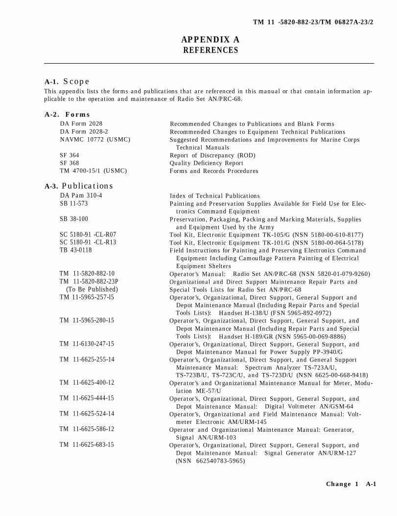
APPENDIX AREFERENCES
A-1. ScopeThis appendix lists the forms and publications that are referenced in this manual or that contain information ap-plicable to the operation and maintenance of Radio Set AN/PRC-68.
A-2. FormsDA Form 2028DA Form 2028-2NAVMC 10772 (USMC)
SF 364SF 368TM 4700-15/1 (USMC)
A-3. PublicationsDA Pam 310-4SB 11-573
SB 38-100
SC 5180-91 -CL-R07SC 5180-91 -CL-R13TB 43-0118
TM 11-5820-882-10TM 11-5820-882-23P
(To Be Published)TM 11-5965-257-l5
TM 11-5965-280-15
TM 11-6130-247-15
TM 11-6625-255-14
TM 11-6625-400-12
TM 11-6625-444-15
TM 11-6625-524-14
TM 11-6625-586-12
TM 11-6625-683-15
Recommended Changes to Publications and Blank FormsRecommended Changes to Equipment Technical PublicationsSuggested Recommendations and Improvements for Marine Corps
Technical ManualsReport of Discrepancy (ROD)Quality Deficiency ReportForms and Records Procedures
Index of Technical PublicationsPainting and Preservation Supplies Available for Field Use for Elec-
tronics Command EquipmentPreservation, Packaging, Packing and Marking Materials, Supplies
and Equipment Used by the ArmyTool Kit, Electronic Equipment TK-105/G (NSN 5180-00-610-8177)Tool Kit, Electronic Equipment TK-101/G (NSN 5180-00-064-5178)Field Instructions for Painting and Preserving Electronics Command
Equipment Including Camouflage Pattern Painting of ElectricalEquipment Shelters
Operator’s Manual: Radio Set AN/PRC-68 (NSN 5820-01-079-9260)Organizational and Direct Support Maintenance Repair Parts andSpecial Tools Lists for Radio Set AN/PRC-68Operator’s, Organizational, Direct Support, General Support and
Depot Maintenance Manual (Including Repair Parts and SpecialTools Lists): Handset H-138/U (FSN 5965-892-0972)
Operator’s, Organizational, Direct Support, General Support, andDepot Maintenance Manual (Including Repair Parts and SpecialTools Lists): Handset H-189/GR (NSN 5965-00-069-8886)
Operator’s, Organizational, Direct Support, General Support, andDepot Maintenance Manual for Power Supply PP-3940/G
Operator’s, Organizational, Direct Support, and General SupportMaintenance Manual: Spectrum Analyzer TS-723A/U,TS-723B/U, TS-723C/U, and TS-723D/U (NSN 6625-00-668-9418)
Operator’s and Organizational Maintenance Manual for Meter, Modu-lation ME-57/U
Operator’s, Organizational, Direct Support, General Support, andDepot Maintenance Manual: Digital Voltmeter AN/GSM-64
Operator’s, Organizational and Field Maintenance Manual: Volt-meter Electronic AM/URM-145
Operator and Organizational Maintenance Manual: Generator,Signal AN/URM-103
Operator’s, Organizational, Direct Support, General Support, andDepot Maintenance Manual: Signal Generator AN/URM-127(NSN 662540783-5965)
Change 1 A-1

TM 11-5820-882-23/TM 06827A-23/2
TM 11-6625-700-10
TM 11-6625-1576-15
TM 11-6625-2658-14
TM 11-6625 -2718-14-1
TM 11-6625-2941-14&P
TM 11-6625-2946-14
TM 11-6625-2953-14
TM 11-6625-2954-14&P
TM 38-750TM 750-244-2
Operator’s, Manual: Digital Readout, Electronic Counter,AN/USM-207 (NSN 6625-00-911-6368)
Organizational, Direct Support, General Support, and Depot Mainte- nance Manual for Distortion Analyzer, Hewlett-Packard Model333A and 334A, (AN/URM-184A)
Operator’s, Organizational, Direct Support, and General SupportMaintenance Manual for Oscilloscope AN/USM-281C (NSN 6625- 00-106-9622)
Operator’s, Organizational, Direct Support, and General SupportMaintenance Manual: Test Set, Radio Frequency, PowerAN/URM-182A
Operator’s, Organizational, Direct Support, and General SupportMaintenance Manual for Counter, Electronic Digital ReadoutAN/USM-459 (NSN 6625-01-061-8928)
Operator’s, Organizational, Direct Support, and General SupportMaintenance Manual for Test Set TS-3354/PRC-68 (NSN6625-01-091-3157)
Operator’s, Organizational, Direct Support, and General SupportMaintenance Manual: Multimeter, AN/USM-451 (NSN 6625-01-060-6804)
Operator’s, Organizational, Direct Support, and General SupportMaintenance Manual (Including Repair Parts and Special ToolsLists) for Signal Generator SG- 1144/U (NSN 6625-01-075-8478)
The Army Maintenance Management System (TAMMS)Procedures for Destruction of Electronics Materiel to Prevent Enemy
Use (Electronics Command)
A-2 Change 1

TM 11-5820-882-23/TM 06827A-23/2
APPENDIX BMAINTENANCE ALLOCATION
Section I INTRODUCTION
B-l. GeneralThis appendix provides a summary of the maintenanceoperations for AN/PRC–68. It authorizes categories ofmaintenance for specific maintenance functions onrepairable items and components and the tools andequipment required to perform each function. This ap-pendix may be used as an aid in planning maintenanceoperations.
B-2. Maintenance FunctionMaintenance functions will be limited to anddefined as follows:
a. Inspect. To determine the serviceability of anitem by comparing its physical, mechanical, and/orelectrical characteristics with established standardsthrough examination.
b. Test. To verify serviceability and to detect inci-pient failure by measuring the mechanical or electricalcharacteristics of an item and comparing those charac-teristics with prescribed standards.
c. Service. Operations required periodically tokeep an item in proper operating condition, i.e., toclean (decontaminate), to preserve, to drain, to paint, orto replenish fuel, lubricants, hydraulic fluids, or com-pressed air supplies,
d. Adjust. To maintain, within prescribed limits,by bringing into proper or exact position, or by settingthe operating characteristics to the specified parameters.
e. Align. To adjust specified variable elements ofan item to bring about optimum or desired perfor-mance.
f. Calibrate. To determine and cause correctionsto be made or to be adjusted on instruments or testmeasuring and diagnostic equipments used in precisionmeasurement. Consists of comparisons of two instru-ments, one of which is a certified standard of known ac-curacy, to detect and adjust any discrepancy in the ac-curacy of the instrument being compared.
g. Install. The act of emplacing, seating, or fixinginto position an item, part, module (component orassembly) in a manner to allow the proper functioningof the equipment or system.
h. Replace. The act of substituting a serviceablelike type part, subassembly, or module (component orassembly) for an unserviceable counterpart.
Repair. The application of maintenance services(inspect, test, service, adjust, align, calibrate, replace)or other maintenance actions (welding, grinding, rivet-ing, straightening, facing, remachining, or resurfacing)
to restore serviceability to an item by correctingspecific damage, fault, malfunction, or failure in apart, subassembly, module (component or assembly),end item, or system.
j Overhaul. That maintenance effort (service/act-ion) necessary to restore an item to a completely ser-viceable/operational condition as prescribed by mainte-nance standards (i.e., DMWR) in appropriate technicalpublications. Overhaul is normally the highest degree ofmaintenance performed by the Army. Overhaul does notnormally return an item to like new condition.
k. Rebuild. Consists of those services/actionsnecessary for the restoration of unserviceable equip-ment to a like new condition in accordance withoriginal manufacturing standards. Rebuild is the highestdegree of materiel maintenance applied to Army equip-ment. The rebuild operation includes the act of return-ing to zero those age measurements (hours, miles, etc.)considered in classifying Army equipments/com-ponents.
B-3. Column Entriesa. Column 1, Group Number. Column 1 lists
group numbers, the purpose of which is to identify com-ponents, assemblies, subassemblies and modules withthe next higher assembly,
b. Column 2, Component/Assembly. Column 2contains the noun names of components, asemblies,subassemblies, and modules for which maintenance isauthorized.
c. Column 3, Maintenance Functions. Column 3lists the functions to be performed on the item listed incolumn 2. When items are listed without maintenancefunctions, it is solely for purpose of having the groupnumbers in the MAC and RPSTL coincide.
d. Column 4, Maintenance Category. column 4specifies, by the listing of a “work time” figure in theappropriate subcolumn (s), the lowest level of mainte-nance authorized to perform the function listed incolumn 3. This figure represents the active time requiredto perform that maintenance function at the indicatedcategory of maintenance. If the number or complexityof the tasks within the listed maintenance function varyat different maintenance categories, appropriate “worktime” figures will be shown for each category. Thenumber of task-hours specified by the “work time”figure represents the average time required to restore anitem (assembly, subassembly, component, module, enditem or system) to a serviceable condition under typical
B-1
TM 11-5820-882-23/TM 06827A-23/2
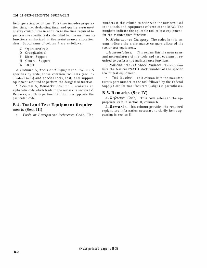
field operating conditions. This time includes prepara-tion time, troubleshooting time, and quality assurance/quality control time in addition to the time required toperform the specific tasks identified for the maintenancefunctions authorized in the maintenance allocationchart. Subcolumns of column 4 are as follows:
C—Operator/CrewO—OrangizationalF—Direct SupportH—General SupportD—Depot
e. Column 5, Tools and Equipment. Column 5specifies by code, those common tool sets (not in-dividual tools) and special tools, test, and supportequipment required to perform the designated function.
f. Column 6, Remarks. Column 6 contains analphabetic code which leads to the remark in section IV,Remarks, which is pertinent to the item opposite theparticular code.
B-4. Tool and Test Equipment Require-ments (Sect III)
a. Tools or Equipment Reference Code. The
numbers in this column coincide with the numbers usedin the tools and equipment column of the MAC. Thenumbers indicate the aplicable tool or test equipment for the maintenance functions.
b. Maintenance Category. The codes in this COl-
umn indicate the maintenance category allocated thetool or test equipment.
c. Nomenclature, This column lists the noun name and nomenclature of the tools and test equipment re-quired to perform the maintenance functions.
d. National/NATO Stock Number. This columnlists the National/NATO stock number of the specifictool or test equipment.
e. Tool Number. This column lists the manufac-turer’s part number of the tool followed by the FederalSupply Code for manufacturers (5-digit) in parentheses.
B-5. Remarks (See IV)a. Reference Code, This code refers to the ap-
propriate item in section II, column 6.b. Remarks. This column provides the required
explanatory information necessary to clarify items ap-pearing in section II.
B-2(Next printed page is B-3)

SECTION II MAINTENANCE ALLOCATIN CHART
Change 1 B-3
(1)GROUP
NUMBER
00
01
0101
TM 11-5820-882-23/TM 06827A-23/2

SECTION III. TOOL AND TEST EQUIPMENT REQUIREMENTS
TM 11-5820-882-23/TM 06827A-23/2
B-4 Change 1
SB 11-30
TM 11-5820-882-23/TM 06827A-23/2
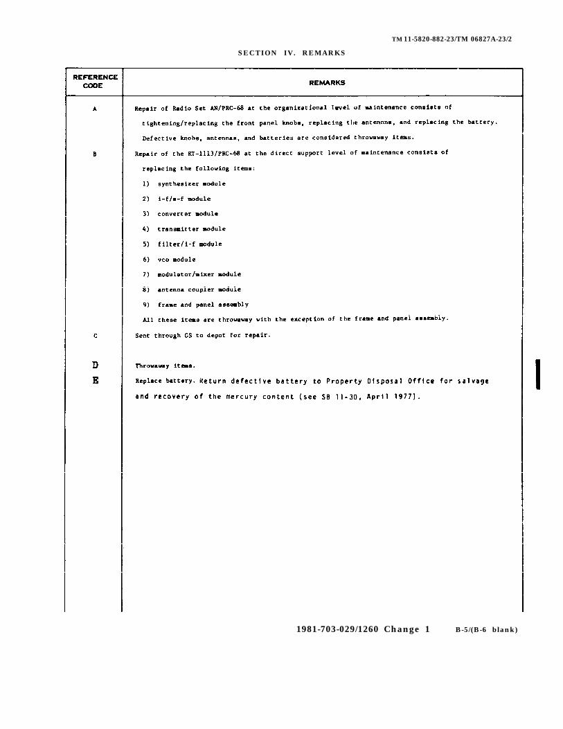
SECTION IV. REMARKS
1981-703-029/1260 Change 1 B-5/(B-6 blank)


TM 11-5820-882-23/TM 06827A-23/2
APPENDIX CEXPANDABLE SUPPLIES AND MATERIALS LIST
Section I INTRODUCTION
1. S c o p eThis appendix lists expendable supplies and materialsyou will need to operate and maintain Radio Set AN/PRC-68. These items are authorized to you by CTA 50-970, Expandable Items (Except Medical, Class V, Re-pair Parts, and Heraldic Items).
2. Explanation of Columnsa. Column 1—Item Number. This number is
assigned to the entry in the listing and is referenced inthe narrative instructions to identify the material (e.g.,“Use cleaning compound, item 5, App. C“).
b. Column 2—Level. This column identifies thelowest level of maintenance that requires the listed item.
(enter as applicable)
C—Opoerator/Crew
O—Organizational MaintenanceF—Direct Support MaintenanceH—General Support Maintenance
c. Column 3—National Stock Number. This is theNational stock number assigned to the item; use it to re-quest or requisition the item.
d. Column 4—Description. Indicates the Federalitem name and, if required, a description to identify theitem. The last line for each item indicates the partnumber followed by the Federal Supply Code for Manu-facturer (FSCM) in parentheses, if applicable.
e. Column 5— Unit of Measure (UM), Indicatesthe measure used in performing the actual maintenancefunction. This measure is expressed by a two-characteralphabetical abbreviation (e. g., ea, in, pr). If the unit ofmeasure differs from the unit of issue, requisition thelowest unit of issue that will staisfy your requirements.
(Next printed page is C-2)
C-1

TM 11-5820-882-23/TM 06827A-23/2
C-2
SECTION II EXPENDABLE SUPPLIES AND MATERIALS LIST

TM 5820-882-23/TM 06827A-23/2
INDEX
SUBJECT Para
Alignment procedures . . . . . . . .. . . .. . . . . . . ... . . . 2-7Ancillary equipment . . . . . . . . . . . . . . . . . . . . . . . 1-6 Antenna replacement . . . . . . . . . .. . . . . . . . . . . . . . 2-7
BatteryFreguency chart . . . . . .. . . . . . . . . . . .. ... . . 2-7cReplacement . . . . . . . . . . . . . . . . . . . . . . .. . . . . . . . . . . . . . 2-18
Cleaning . . . . . . . . . . . . . . . . . . . . . . . . . . . . . .. . . . . . . . . . . .2-14Common tools and equipment . . . . . . . . . . . . . . . . . . . . . . .. . . . .. .. . 2-1Component location . . . . . . . . . . . . . . . . . . . . . . . . .. . . . .. . . .. . 1-7
Data, tabulated . . . . . . .. . . . . . . . . . . . . . . . . . . . . . . . .. . . . . 1-8Destruction to prevent enemy use . . . . . . . . . . . . . . . . . . . . . . . . . . . .. . . . .1-3Disassembly instructions . . . . . . . . . . . . . . . . . . . . . .. . . .2-5
Equipment capabilities . . . . . . . . . . . . . . . . . . . . . . . . . . . . . . . . . . . . .. . 1-6Equipment improvement recommendations .. .. . . . . . . . .. . . . . 3-7
Fault isolation . . . . . . . . . . . .. . . . . . . . . . . . . . . . . . .. . . . . .. . . . . . .. . . .. 3-7
Knob replacement . . . . . . . . . . . . . . . . . . . . . . . . . . . . . . . . . . . . . . . 2-16
LubricationGasket seal-----------------------------------------------------------6-6
MaintenanceDirect support . . . . . . . . . . . . . . . ... . . . . ... . . . . . . . . . . . . . . . 3-1Kit----------------------------------------------------------3-3
Organzational------------------------------------------------------2-13Preventive . . . . . . . . . . . . . .. . . . . . . . . . . . . . . . . . . . . . . . . . . . ..2-8
ModulesPin straightening . . . . . . . . . . . . . . .. . . . . . . . . . . . . . . . . . . . . . . .3-11Removal and replacement . . . . . . . . . . . . . . . . . . . . . . . . . . . . . . 3-10
Painting-----------------------------------------------------------------2-15
Reassembly instructions .. . . . . .. . . . . . . . . . . .. . . . . . . . . . 2-6Receiver operation
Orgntiational . . . . . . . . . . . . . . . . . . . . . . . . . . . . . . . 1-10Direct support . . . . . . . .. . . . . . . . . . . . . . . . . . . . . . . . .. . . . . .3-16
Repair parts . . . . . . . . . . . . . . . . . . . . . . . . . . . . . . . . . .2-3
Storge --------------------------------------------------------------2-19SVM operation . . . . . . . . . . . . . . . . . . . . . . . . . . . . . . . . . . . . . . . .1-12Switch code . . . . . . . . . . . . . . .. . . . . . . . . . . . . . . . . . . . . . . . . . . . . 2-7dSynthesizer operation . . . . . . . . . . . . . . . . . . . . . . . . . . . . . . . . . . . . . 3-18
Test point locations . . . . . . . . . . . . . . . . . . . . . .. . . . . . .3-9Test set . . . . . . . . . . . . . . .. . . . . . . . . . . . . . . . . . . . . . . . . . . . . . .. 2-12Tools
Common . . . . . . . . . . . . . . . . . . . . . . .. . . . . . . . . . . . . . . . . . . . . .. .. 3-1Special . . . . . . . . . . . . . . . . . . . . . . . . . . . . .. . . . . . . . . . . .. 3-2
Transmitter operationOrgnizational . . . . . . . . . . . . . . . . . . . . . . . . . . . .. . . . . . . . . .. . 1-11Direct Support . . . . . . . . . . . . . . . . . . . . . . . . . . .. . . . . .. . . . . . . . .. 3-17
Troubleshooting proceduresOrganizational -----------------------------------------------------2-11Direct support . . . . . . . . . . . . . . . . . . . . . . . . . . . . . . . . .. . . . . 3-5
● U.S. GOVERNMENT PRINTING OFFICE : 1995 0 - 388-421 (01391) Index-1


TM 11-5820-882-23/TM 08827A-23/2
Figure FO-1. Radio Set Block Diagram (Sheet 1 of 2).
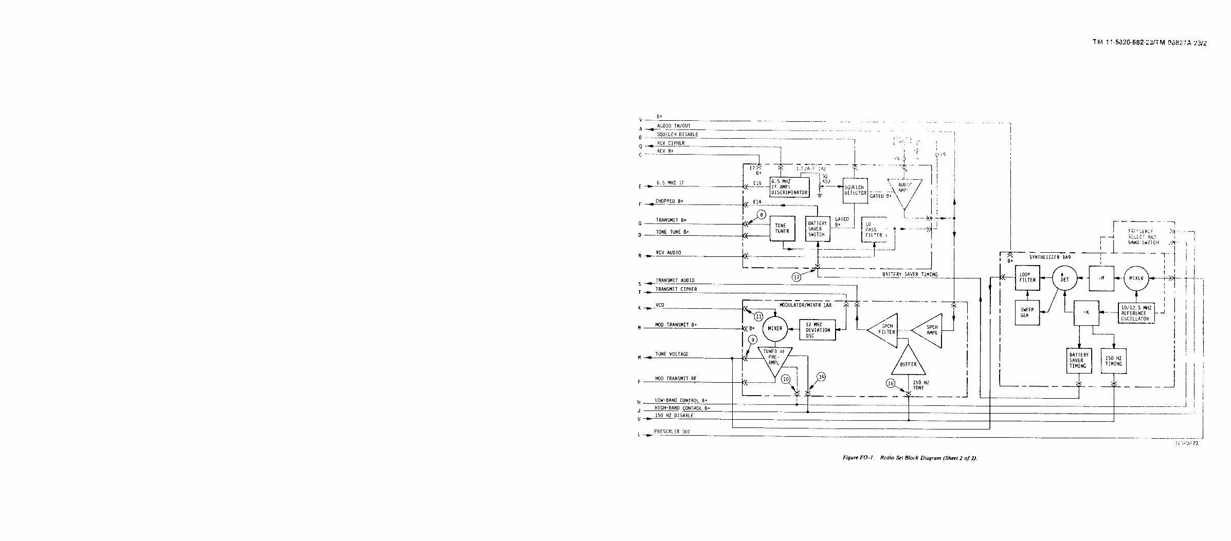
Figure FO-1. Radio Set Block Diagram (Sheet 2 of 2).
TM 11-5820-882-23/TM 08827A-23/2

By Order of the Secretary of the Army and the Navy:
Official:
J. C. PENNINGTONMajor General, United States Army
The Adjutant General
E. C. MEYERGeneral, United States Army
Chief of Staff
H. A. HATCHMajor General, US Marine Corps
Deputy Chief of Staff for Installationsand Logistics
Distribution:

PIN ;047728-000