technical manual - promega
TRANSCRIPT

TD-20/20 Luminometer Operating Manual
Page 1
TD-20/20Luminometer
OperatingManual
Dated: 02/20/2003Version 2.5
Part Number 2020-998

TD-20/20 Luminometer Operating Manual
Page 1
TD-20/20Luminometer
OperatingManual
Dated: 02/20/2003Version 2.5
Part Number 2020-998

TD-20/20 Luminometer Operating Manual
Page 2
TD-20/20 LuminometerOperating Manual
Table of Contents
I. Introduction 5A. DescriptionB. Inspection and SetupC. Sample Holder and AdaptorsD. Definition of SymbolsE. General Precautions
II. Hardware Overview 8A. TD-20/20 Quick View DiagramB. TD-20/20 Controls
III. Instrument Parameters (Software) 10A. Firmware FlowchartB. Power-up ScreenC. HOME ScreenD. Setup/Mode ScreenE. Setup ScreensF. Mode Screen
IV. Subtracting the Reagent Background 14
V. Data Stream Capability 16
VI. Auto Injector 18A. Automatic Injector System- MechanicalB. Installation (Configuring for Operation)C. Auto Injector ScreensD. Normal OperationE. Daily CleaningF. Trouble-ShootingG. Important Notice to Users of Promega's Dual-LuciferaseTM Reporter AssayH. Specifications
VII. Reading Samples 25
VIII. Reset Sample Number Index 26
IX. Sensitivity Adjust 27A. Why Adjust Sensitivity?B. ProcedureC. To View or Print the Last Sensitivity AdjustD. To Abort the Sensitivity Adjust
X. Range Extender 29A. PurposeB. How to UseC. To Determine the Correction Factor for the Range Extender

TD-20/20 Luminometer Operating Manual
Page 3
APPENDICES
APPENDIX 1 - The Printout 30A. Printout Capability with a Printer or ComputerB. Sample Reading with a Printer or Computer
APPENDIX 2 - Data Collection 32
APPENDIX 3 - Spreadsheet Interface Instructions 33A. IntroductionB. Materials RequiredC. Software Installation InstructionsD. Connecting the TD-20/20 to your PrinterE. Starting the ProgramF. Selecting the COM PORTG. Aquiring DataH. TroubleshootingI. Pause, Stop, & CloseJ. High Level FunctionsK. Data Format
APPENDIX 4 - Glossary 37
APPENDIX 5 - Alarms and Diagnostics 39A. Alarm ScreenB. Diagnostic ScreensC. Troubleshooting
APPENDIX 6 - Error Messages and Notes 41A. Invalid InputB. Home Screen Displays >9999
APPENDIX 7 - Maintenance, Warranty, and Service 42A. MaintenanceB. WarrantyC. Obtaining Service
APPENDIX 8 - Specifications and Features 44
APPENDIX 9 - Specifications and Features: German Translation 45

TD-20/20 Luminometer Operating Manual
Page 4
Model TD-20/20 LuminometerCalibration Record Sheet
(This information is specific to your TD-20/20 Luminometer)
TD-20/20 Luminometer Serial Number: Date:
Factory 14C Sealed LSC Standard Unit #: Factory Standard Reading (RLU):
Initials: Date:
Customer 14C Sealed LSC Standard Unit #*: ________________________________
Customer Standard Reading*(RLU)
1. ___________________________________________________________________
2. ___________________________________________________________________
3. ___________________________________________________________________
Average Standard Reading:
Standard Deviation:
% CV**:
* Applies only if customer has purchased P/N 112-0220 Light Standard
** %CV= (Standard Deviation X 100)/Average

TD-20/20 Luminometer Operating Manual
Page 5
I. Introduction
A. Description
The TD-20/20 Luminometer is a sensitive, compact Luminometer designedfor use in molecular and cellular biology using firefly luciferase as a geneticreporter; for measuring live biomass using the ATP assay; for use inimmunological studies with chemiluminescence technologies; and for use invarious biochemical applications. The sample chamber and adaptor aredesigned to accommodate a variety of sample holders. Sensitivity may beincreased or decreased with ease using the keypad.
B. Inspection and Setup
Upon receiving your Luminometer, please inspect it carefully and make sureall accessories are present (refer to the packing list shipped with theinstrument).
To get started (refer to the Quick View Diagram, Section IIA):
1. Consider the following factors for location:
a. Locate the instrument on a flat surface;b. Since temperature can affect results, the work area should be free
from hot or cold drafts and away from windows or heaters;c. Many luminescent reagents are sensitive to light, particularly
ultraviolet light. Therefore, when locating the instrument:1. Avoid sunlight;2. Avoid fluorescent lighting;3. Incandescent lighting is usually acceptable; reflected light ispreferred to direct light.
2. Open the sample chamber lid located on the top of the unit. The lid willhave a little resistance. Avoid leaving the lid open for extended periods oftime.
3. Remove the sample adaptor by grasping and pulling up.
4. If using the range extender, See Section X for details.
5. Position the sample adaptor in the correct position for your needs. Referto Section C for a detailed explanation of the TD-20/20 Sample Adaptor.
6. Reinsert the positioned sample adaptor by sliding it into the chamber.Insert the correct sample holder for your needs. Close the samplechamber lid. The lid has been designed to prevent sudden closure, sothere will be a little resistance.
7. If the auto-injector system will be used, set it up at this time. SeeSection VI.
8. Plug in the unit. Be sure to use only the Turner Designs powersupply provided with your instrument. It is critical to use the powersupply provided by Turner Designs to meet EMI requirements.
1.5 ml Microfuge TubeHolder, 8 mm Test Tube
Holder, and 12 mm Test TubeHolder
Sample Adaptor and Holder
Sample Adaptorand 35 mm culture dish
TD-20/20 Side View
Sample Adaptor →

TD-20/20 Luminometer Operating Manual
Page 6
9. Turn on the power switch (rear of unit) and allow the unit to warm up forthe countdown period (300 seconds; 5 minutes).
C. Sample Adaptor and Holders
The TD-20/20 has been designed to hold a variety of sample containers. It willaccommodate: 8 x 50 mm tubes; 12 x 50 mm tubes; 28 mm scintillation vials;35 mm culture dishes; and 1.5 ml microfuge tubes.
Installing and Removing Sample Adaptor and Holders
The TD-20/20 Luminometer comes equipped with a sample adaptor thataccommodates 35 mm culture dishes; when "flipped over", it will hold the 28mm scintillation vials, or sample holders. Sample holders are available for 8 x50 mm test tubes, 12 x 50 mm test tubes, and 1.5 ml microfuge tubes.These holders slide into the 28 mm opening of the sample adaptor.
To switch from 35 mm culture dishes to 28 mm vials:
1. Open the lid to the sample chamber.
2. Grasp the sample adaptor by the rim and pull straight up.
3. Remove any samples present.
4. "Flip" it over and slide it back into the chamber until it is fully seated.
To install the 8 x 50 mm, 12 x 50 mm, or 1.5 ml microfuge tubeadaptors:
1. Open the lid to the sample chamber.
2. Make sure the sample adaptor is facing properly (see the drawing to theleft).
3. Slide the appropriate holder inside the sample adaptor and push downuntil it is fully seated.
D. Definition of Symbols
Direct Current. 12 volts D.C.Gleichstrom
Caution. Read instruction manual and refer to warning text.Vorsicht. Lesen Sie die Anweisungen und die Warnung.
E. General Precautions
1. If the equipment is used in a manner not specified by the manufacturer, theprotection provided by the equipment may be impaired.Sollte das Gerät in einer Weise benützt werden die nicht vom Herstellerspecifiziert ist, kann es möglich sein das die Wirkungskraft desInstruments auf diese Weise beschädigt wird.
1.5 ml Centrifuge VialHolder, 8 mm Test TubeHolder, and 12 mm Test
Tube Holder
Sample Adaptor and Holder
Sample Adaptorand 35 mm culture dish

TD-20/20 Luminometer Operating Manual
Page 7
Before Sensitivity Adjust or Reading Samples
2. Materials Needed
l Sufficient sample containers. Sizes: 8 x 50 mm tubes; 12 x 50 mmtubes, 28 mm scintillation vials; 35 mm culture dishes; 1.5 ml microfugetubes.
l Assemble and prepare any reagents necessary for the assay to be run.Refer to any applications notes or procedures available.
l Samples to be read.
3. When Handling Samples
l Take care not to spill samples into the sample chamber. Wipe up anyspills promptly. See Appendix 7, Section A, for details on maintenance.
l The cuvette MUST BE DRY on the outside when taking readings.Moisture on the outside will result in error.
4. Temperature Considerations
Most luminescent reactions will be measured at ambient temperature. Aslong as large temperature variations do not occur during a run, measuring thestandard(s) and samples at the same temperature will be sufficient to ensureaccuracy. ATP determination is an extreme example of this. Despite the factthat the reagent is an enzyme, temperature variation of several degrees willnot result in significant error.
Additional temperature control will be desirable when:
l Laboratory temperature varies widely;l Operation will occur at a temperature other than ambient.
To provide additional temperature control, obtain a waterbath that meetsnecessary temperature requirements and sample and reagent capacity.

TD-20/20 Luminometer Operating Manual
Page 8
Sample Adaptorand 35 mm culture dish
TD-20/20 Luminometer
Display
Keypad
Sample Chamber
Sample Adaptorand Holder
1.5 ml Microfuge Tube Holder,8 mm Test Tube Holder, and
12 mm Test Tube Holder
II. Hardware Overview
A. TD-20/20 Quick View Diagram

TD-20/20 Luminometer Operating Manual
Page 9
TD-20/20 Rear View
B. TD-20/20 Features
1. Display - Shows the screens and readout for samples. It is litcontinuously when the unit is operating. Except during SensitivityAdjust, the contrast of the display can be adjusted on any screen bypressing the up or down arrow keys.
2. Keypad - The keypad is used to enter new values and to movethrough the software screens.
3. Lid - The lid has been designed to ensure proper closure and tomaintain a light seal. To prevent sudden closure, the lid is hinged andsome resistance will be felt when closing it. The lid is designed to holdan auto-injector delivery system, which screws into the opening in thelid. If the TD-20/20 is not set up for auto-injection, the opening will besealed with a black plug.
4. Sample Chamber - Samples are placed inside the chamber forreading. The chamber houses the sample adaptor, sample holder,range extender & LightSwitchTM module.
5. Sample Adaptor and Holders - The sample adaptor accommodates35 mm culture dishes; when "flipped over" it holds 28 mm scintillationvials, and the sample holders. Sample holders, which slide inside thesample adaptor, are available for 8 x 50 mm round test tubes, 12 x 50mm round test tubes, and 1.5 ml microfuge tubes.
6. Power Switch - ON/OFF switch.
7. RS-232 Serial Port Connection - RS-232 (DB9 female from the TD-20/20) serial port for connecting to a computer or printer.
8. Power Plug Socket - The power supply connects into the rear panelof the instrument.
9. Auto-Injector - The auto-injector is mounted inside the rear panel ofthe instrument and is activated from the TD-20/20 keypad.
7
6
8
9
Sample Adaptor and Holder
1.5 ml Microfuge TubeHolder, 8 mm Test Tube
Holder, and 12 mm Test TubeHolder
5
5
Sample Adaptorand 35 mm culture dish
5
3
1
4
2

Turner Designs2020 -1F 0302 300
bR## XXXX.XRdy
Data Stream?Yes <No>
Oper:XXX HrsPwr Level: 100%
Sen %: XX.X
Turner Designs2020 -1F 0302
Blk: X.XXX1. OK 2.Clr 3.New7
8
9
INJ
1
2
3
Reset to 0?1. OK 9. No
Average how many? (1-5): X <ENT>
Insert blank #1then press <GO>
Delay: X.XXX XXReading Blank #1
Blk1 X.XXXInsert #X <GO>
BlkX X.XXXFinish <ENT>
1. Setup Inj #12. Setup Inj #2
Inj #X: XXX ul1. Prime 9.Vol
Old (50-250) = XXXNew: 0=OFF
Delay: 0.000 XX<ESC> - Abort
Int: XXXX XX<ESC> - Abort
bR## XXXX.XRdy
Delay: 0.000 XX<ESC> - Abort #1
Int: XXXX XX<ESC> - Abort #1
Int: XXXX XX<ESC> - Abort #2
Delay: 0.000 XX<ESC> - Abort #2
Press <GO>when ready
bR## XXXX XXXXRatio: X.XXX Rdy
STD mode
DLR mode
Press 1 or 2 to see
Press 9 to see
Firmware version
Press <ENT> to see
Press theçè key totoggle
If inj #2 is not used,you will see
Printing
Blk: X.XXX1. OK 2.Clr 3.New
Blk: X.XXX1. OK 2.Clr 3.New
bR## XXXX.XRdy
Press 1 or 9 to see
Press <ENT> to see
Press <GO> to see
Int: X.XXX XXReading Blank #1
Home Screen:b indicates blank subtraction activatedR# represents current replicate, if replicate is >1XXXX is the reading of the last sample
Warm up screen:Countdown from 300
1 Reset sampleindex? 1. Confirm
Sample indexhas been reset
Press 1 to see
GO 0
III. Instrument Parameter (Firmware)A. Firmware FlowchartPage 10

1. Delay 3. Reps2. Integrate Time
Int= XXX sec1. OK 9. Change
Old (0-6000) = XXXXNew:
Delay = XX sec1. OK 9. Change
Old (0-100) = XXNew:
Replicates = XX1. OK 9. Change
Old (0-20) = XXNew:
Mode:<STD> DLR
Up/Down arrowsset sensitivity
Sen%: XX.XRLU: XXXX <ENT>
Insert Standardor Sample <ENT>
1. Change Sens9. Set to Default
Setup
1. Setup2. Mode: XXX
Printing
Invalid Input<ENT> to reenter
Std/Sample setto: XXX.XXX
1
2
1
3
Press 9 to see
Press 1 to accept
Press <ENT> to accept
Press 1 to accept
Press 9 to see
Press <ENT> to accept
Press 1 to accept
Press 9 to see
2
Press theçè key totoggle
9 8 88
Printing
1
bR## XXXX.XRdy
9
Press <ENT> to see
Press arrows to see
Press <ENT> to see
If a value is entered > stated
range, you will see:
Page 11

TD-20/20 Luminometer Operating Manual
Page 12
III. Instrument Parameters (Software)
Instrument parameters are set through the TD-20/20 Firmware interface.Screens are called up using the keypad. Use Sections III-X for explanationsof the various parameters. For details about alarms and instrumentdiagnostics, see Appendix 5.
B. Power-up Screen
When the unit is first turned on, a screen appears showing the title, softwareversion, and a 300-second (5-minute) countdown. Once the 300-secondcountdown expires, the HOME screen will appear. The countdown allows theinstrument to warm up adequately before measurements begin. For optimalstability and accuracy, it is recommended that you allow the instrument tocomplete the countdown period.
If you wish to bypass the countdown period, press <HOME>, <ESC>, or<ENT>. From the HOME screen, press <9> to return to the Power-upscreen.
C. HOME Screen
After the countdown period, the HOME screen is displayed. The HOMEscreen is where samples are read and data is sent to the printer orcomputer. The reading on the HOME screen will be static until <GO> ispressed to activate the integration sequence. The HOME screen displayssample readings to 4 significant figures (0.001 to 9999). To the left of thesample reading is the replicate number. A 'b' to the left of the replicatenumber indicates that a blank is stored in the instrument's memory and isbeing subtracted.
Press <HOME> to return to this screen from any screen (except during theSensitivity Adjust sequence).
From the HOME screen, several functions can be accessed.
- Press <GO> to begin the “Integration” sequence (See Section III E fordetails). If an auto-injector is being used, this will trigger the auto-injector.
- Press <8> for Diagnostic Screens.- Press <ESC> when an alarm is active (ALM) to view the alarm.- Press <SETUP> to access the Setup/Mode Screen.- Press <7> to turn on the data stream option.- Press <0> to subtract blank.- Press <1> to reset sample #.
D. Setup/Mode Screen
From the Setup screen, accessed from the HOME screen by pressing<SETUP>, the user can review or change the setup parameters. Pressing<SETUP> again from this screen sends the current Sensitivity Adjustinformation to a printer or computer.
bR# XXX.XXXRdy (or) ALM
HOME Screen
Turner Designs2020-1F 0302 300
Power-up Screen
1. Setup2. Mode
Setup/Mode Screen

TD-20/20 Luminometer Operating Manual
Page 13
E. Setup Screens
To access the SETUP screens, from the HOME screen press <SETUP>,then press <1> to access the Setup parameters. From the SETUP screen,press the appropriate number to access the parameter: <1> Delay; <2>Integrate Time; <3> Replicates. To change a value, press <9>, then enterthe new value on the keypad and press <ENT>.
Integration Sequence. When a sample is read, the reading is integrated,or “summed” for a user-set Integrate period after a user-set Delay period.
1. Delay Period. The delay period is part of the Integration sequence. TheIntegration sequence is started from the HOME screen by pressing<GO>. The Delay period is the time the instrument waits before theonset of the Integrate period after <GO> is pressed. The delay allowstime for the sample to stabilize, and for such factors as fading away oflight-induced luminescence. The default Delay period is 3 seconds; therange is 0-100 seconds.
2. Integrate (Int) Period. The Integrate period is the time over which theinstrument averages the reading of a sample. The Integration sequenceis started from the HOME screen by pressing <GO>. After <GO> ispressed, the Delay period will run, followed by the Integrate period. If theTD-20/20 is connected to a printer or computer, the sample reading willprintout automatically at the end of the Integration sequence. The defaultIntegrate period is 15 seconds; the range is 4-6000 seconds.
3. Replicates. This screen allows the user to select the number ofreplicates (measurements of similar samples). If 1 is selected, theinstrument will read and display the one sample only. If 2 or morereplicates are selected, the instrument will read the first sample anddisplay the measurement at the end of the integration sequence. Thenext replicate is then inserted and <GO> is pressed to start the reading.After all replicates are analyzed, the instrument will print or send to acomputer the average of the replicates, the % variation of themeasurements, and the standard deviation of the measurements. Areplicate reading can be deleted and rerun by pressing the delete keyafter the sample is read. The default number of replicates is 1; the rangeis 1-20.
NOTE: The statistics cannot be viewed unless the TD-20/20 isconnected to a printer or computer. See Appendix 1 and 2 for furtherdetails.
F. Mode Screen
To access the MODE screen, from the HOME screen press <SETUP>, thenpress <2> to access the MODE screen. Toggle between DLR and STDmodes by pressing the left/right arrow key. If you are using Promega's dualluciferase reporter (DLR) assay or using the LightSwitchTM module for dualcolor assays, you may operate in the DLR mode. Otherwise, you shouldoperate in the standard (STD) mode. For more information on Promega'sDLR assay, contact Promega at 800/356-9526.
1. Delay 3. Reps2. Integrate Time
Setup Screens
Mode:<STD> <DLR>
Mode Screen

TD-20/20 Luminometer Operating Manual
Page 14
IV. Subtracting the Reagent Background
In some cases, reagents have an intrinsic background luminescence thatcontributes to the luminescence readings of samples and standards.Subtracting the background from these readings results in greater accuracyin measurements. This procedure is called blank subtraction. The blanksubtraction technique used here involves running one or more blanks,averaging the results to get a composite blank value, and subtracting thisvalue from any subsequent sample measurements.
1. Press <0> from the HOME screen to start the procedure. The screenshown will display the current blank value(s) and show three choices
a) 1. OK – Choosing this option will send the current blank data to theprinter and return the user to the HOME screen.
b) 2. CLR – Choosing this option will clear the current blank data fromthe luminometer’s memory and reset it to 0.000.
c) 3. New – Choosing this option will allow the user to run up to 5 blanksamples and average the data to form a new blank value.
2. If you elected to run a new blank, “Average how many? (1-5)” will bedisplayed on the screen. Enter the number of blanks you wish tomeasure. The average of the blank measurements will be used as thefinal blank number to be subtracted from the sample reading.
3. “Insert blank #1 then press <GO>“ will be displayed. Press <GO> to runthe first blank.
4. After the blank is complete, the blank value is displayed. The user isprompted to press <GO> to run the next blank. Remove the first blanksample and insert the second blank sample before pressing <GO>.
5. Repeat step 4 until all the blanks are run.
6. Normally, the user would skip this step and move on to step 7, but if youmake an error running one of the blanks in step 5, press the <ESC> keyto delete the most recent blank run, or to quit the blanking procedurewithout completing it. When pressing <ESC>, the user sees “DeleteLast?” with three choices: 1.No, 2.Yes, 3.Quit
a) 1. No – The user selects this option if he does not want to deleteany blanks that have been run. Choosing “No” returns the user tothe previous screen.
b) 2. Yes – Selecting this option deletes the last blank run and returnsthe user to the screen where another blank can be run in its place.
c) 3. Quit – Selecting this option allows the user to quit and keep theblanks already run, or quit and ignore any blanks run.

TD-20/20 Luminometer Operating Manual
Page 15
7. Following the last blank, the message “Finish <ENT>” will be displayedon the bottom line of the screen. Press <ENT> to see the new averageblank value.
8. The screen that appears is the same as in Step 1. Choose “1. OK” toprint the blank value. The user is now returned to the HOME screen.
9. To alert the user that there is a blank value stored and being subtractedfrom the measurements, a “b” appears in the upper left corner of theHOME screen display.
Since there are two modes of analysis in the TD-20/20, DLR andStandard, there are two different blanks. The blank values saved in theDLR mode are not transferred to the Standard mode (or visa versa).NOTE: Toggling between modes does NOT erase the stored blankvalues of either mode.

TD-20/20 Luminometer Operating Manual
Page 16
Section V.Data Stream Capabilities
Several luminometric applications require the ability to monitor luminescenceover time. The data stream feature allows this capability. When the datasteam feature is on, the TD-20/20 outputs the real-time data continuouslythrough the RS-232 port until actively stopped. This data may either bereceived by a printer or a computer.
General Information:
l Parameters in the Setup Screen (Delay, Integrate, and Replicates)are not active during Data Stream analysis
l Both or Either Injector can be used. The 1st injector will activatewith pressing the [GO] button. The 2nd injection will startimmediately after the 1st injection finishes.
l The Data output rate is fixed at 5 readings/second
Procedure:
1. From the "Mode" Screen, set the TD-20/20 to STD mode. Press the[HOME] key to return to the Home Screen.
2. Press [7] to access the Data Stream Screen.
3. Use the <-> key to toggle the parenthesis to select "yes".
4. Press the [HOME] key.
5. Set up the Auto Injectors, if they are to be used.
6. Press [GO]. Real Time Data will be viewable on the LCD Screen,refreshed 1/second. Data sent out to a printer or computer will be atthe rate of 5 readings/ second.
7. Press [ESC] to stop the readings.
Data Output:
With Printer or Terminal Program
0.000 - Current Value of Subtracted blank- Empty
200.0184.8188.9185.3189.8186.4196.7aborted
Data Stream<Yes> No
Data Stream Screen
Data Stream Dataevery 0.2 seconds

TD-20/20 Luminometer Operating Manual
Page 17
With Spreadsheet Interface Software
9.5069 - Time stamp in decimal format (9.5069 = 9:30:25AM)0.000 - Current Subtracted Blank Value
200.0184.8188.9185.3 Data Stream Data189.8 at 0.2s intervals186.4196.7aborted
See Appendices 1-3 for further details on using printers or computer to capture/report data.

TD-20/20 Luminometer Operating Manual
Page 18
VI. Auto-Injector
A. Automatic Injector System - Mechanical
The TD-20/20 has been designed to operate with an automatic injectorsystem. This factory-installed option is simple to operate and easy tomaintain. Single or dual pump configurations are available.
It is important to understand the internal design of the injector pumpbecause it allows the user to achieve optimum injector performance. Thedual injector system consists of two sequential single injectors.
This system has been designed to use water-based reagents andsolutions. It is critical that factory-supplied tubing be used. Please refer tothe SPECIFICATIONS SECTION for fluid compatibility.
The injector pump operates by using a fluid displacing plunger to draw inand expel fluid. Flow is controlled by inlet and outlet check valves.
B. Installation (Configuring for Operation)
1. Using a coin, remove the black plug on the sample compartment lid.
2. Install the single or dual needle adapter into the sample compartmentlid. The adapter should screw snugly into the lid to prevent any lightleakage. Remove dust plugs from the injector pump head. Connect theinjector tubing to the upper pump fitting(s).
3. Install the reagent bottle holder clip adjacent to the injector. Insert thereagent bottle into the holder clip.
4. Connect the supply line(s) to the inlet (lower pump fitting). Place thesupply line into the reagent bottle and make certain it is at the bottlebottom.
NOTE: Exercise care in keeping contaminants such as lint, dirt, anddust from collecting on the supply line inlet. This can plug the injectorvalves and nozzle resulting in less than optimal performance.
5. At this point the supply and injector tubing is connected to the pumps,and supply tubing is inserted into the reagent fluid. The system isconfigured for normal operation. Proceed to the next section (NormalOperation).
FERRULE
M-6 FLANGELESS FITTING
TUBING
INJECTORADAPTER
INJECT
ASPIRATE
SINGLE
INJECTORADAPTER
INJECT
ASPIRATE
DUAL
OUTLET VALVE
INLET VALVE
SUPPLY LINE
REAGENT
TO SINGLE INJECTOR
SEAL
PISTON
REAGENT
SUPPLY LINE
INLET VALVE
OUTLET VALVE
SEAL
PISTON
Single Injector
Dual Injector
Fitting Connector
Injector Sample Holder
TD-20/20 Luminometer Operating Manual
Page 19
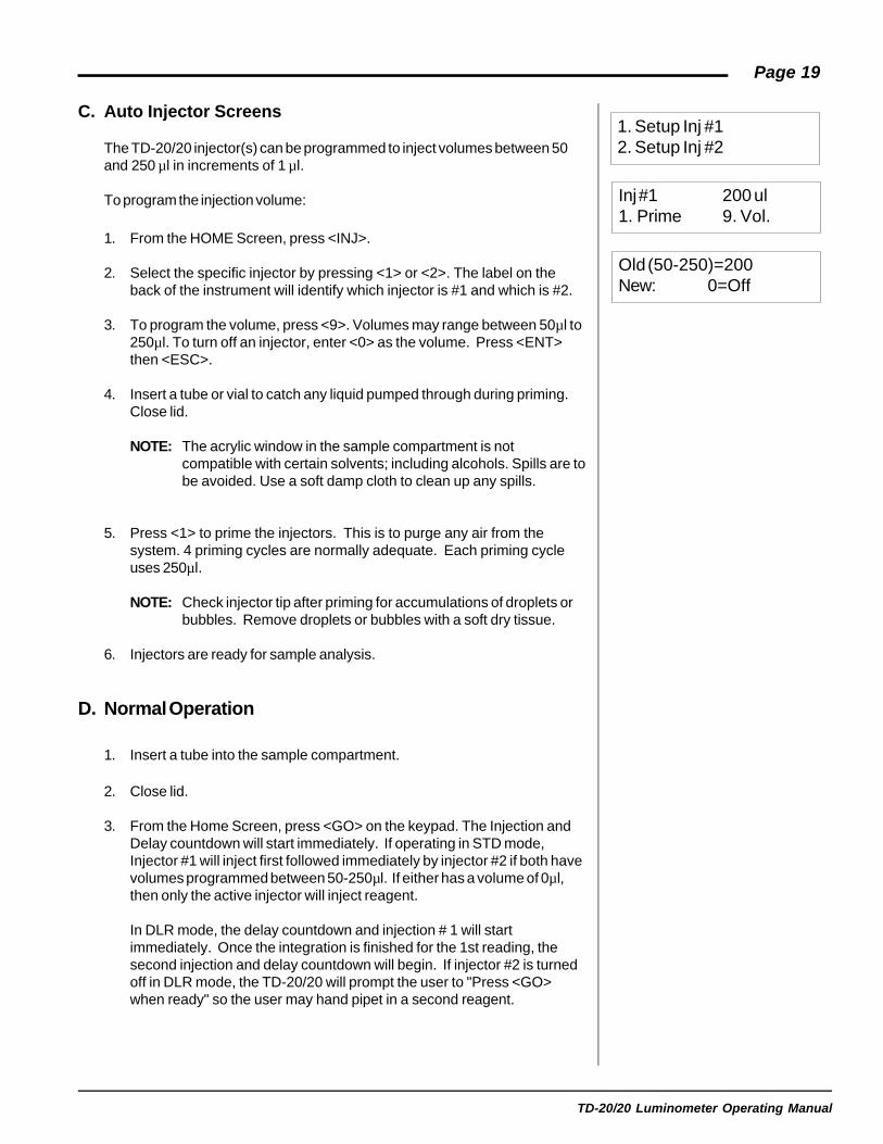
1. Setup Inj #12. Setup Inj #2
Inj #1 200 ul1. Prime 9. Vol.
Old (50-250)=200New: 0=Off
C. Auto Injector Screens
The TD-20/20 injector(s) can be programmed to inject volumes between 50and 250 µl in increments of 1 µl.
To program the injection volume:
1. From the HOME Screen, press <INJ>.
2. Select the specific injector by pressing <1> or <2>. The label on theback of the instrument will identify which injector is #1 and which is #2.
3. To program the volume, press <9>. Volumes may range between 50µl to250µl. To turn off an injector, enter <0> as the volume. Press <ENT>then <ESC>.
4. Insert a tube or vial to catch any liquid pumped through during priming.Close lid.
NOTE: The acrylic window in the sample compartment is notcompatible with certain solvents; including alcohols. Spills are tobe avoided. Use a soft damp cloth to clean up any spills.
5. Press <1> to prime the injectors. This is to purge any air from thesystem. 4 priming cycles are normally adequate. Each priming cycleuses 250µl.
NOTE: Check injector tip after priming for accumulations of droplets orbubbles. Remove droplets or bubbles with a soft dry tissue.
6. Injectors are ready for sample analysis.
D. Normal Operation
1. Insert a tube into the sample compartment.
2. Close lid.
3. From the Home Screen, press <GO> on the keypad. The Injection andDelay countdown will start immediately. If operating in STD mode,Injector #1 will inject first followed immediately by injector #2 if both havevolumes programmed between 50-250µl. If either has a volume of 0µl,then only the active injector will inject reagent.
In DLR mode, the delay countdown and injection # 1 will startimmediately. Once the integration is finished for the 1st reading, thesecond injection and delay countdown will begin. If injector #2 is turnedoff in DLR mode, the TD-20/20 will prompt the user to "Press <GO>when ready" so the user may hand pipet in a second reagent.

TD-20/20 Luminometer Operating Manual
Page 20
E. Daily Cleaning
Turner Designs recommends cleaning the injection system at the end ofevery day of use and when changing applications/reagents.
To clean:1. Insert a tube or vial large enough to catch the liquid pumped through the
injectors.
2. Remove supply tubing from the reagent bottles.
3. Using the priming cycle, purge all reagent from the injectors.
4. Insert supply tubing into DI water and prime the injectors 10 times torinse the system.
5. Insert supply tubing into 70% ethanol solution and prime 6-10 times.Allow this solution to sit in the system for 1-16 hours for a thoroughcleaning.
6. Purge the 70% ethanol solution and rinse systems 10 times with DIwater.
7. Purge water.
F. Trouble-Shooting
This injector has been designed with materials and components offeringsuperior reliability. Testing has shown that dirt and fluid contamination in thesupply fluid has the greatest effect on pump performance. Contaminants cancause the injector tip to become obstructed or plugged. They also result inaltering the performance of the check valves resulting in erroneous fluidmetering. This requires a degree of care be used with regard to cleanliness.See Expanded Maintenance section below for detailed explanations of usermaintenance.
Symptom Possible Cause Corrective ActionAir bubbles Loose tubing connections. Check tubing fittings at inlet andafter priming outlet for tightness.
Injection weak Obstruction in the Remove affected injector supplyand dripping tubing. and output tubing. Flush with clean
water in opposite direction of flow orreplace.
Injection weak Obstruction in the Remove valves flush injector andand dripping after pump check valves. replace valves with new units.tubing replacement.
Drip on injector The reagent fluid is Add reagent. Place supply tubingneedle tip, air in line. depleted or the supply inlet into the reagent.
inlet tubing is abovethe reagent fluid level.

TD-20/20 Luminometer Operating Manual
Page 21G. Maintenance
As a general precaution, we recommend replacing the valves every 6 monthsand the tubing,nuts and ferrules every 12 months to ensure properfunctioning of the injection systems. A replacement tubing and valve kit(P/N 2020-964) is available for this periodic maintenance.
See Section VI E for directions for Daily Cleaning.
Valve Replacement:
If the inlet and outlet flow valves become contaminated or obstructed, theymay either leak or not pass fluid during the pump cycle. If the volumeinjected is inconsistent, it is likely that the valves need to be changed. Youcan avoid this condition by cleaning the injectors at the end of each day ofuse (See Section VI E). To replace the valves do the following:
1. Disconnect the sample input and sample output lines at the injector byunscrewing the end fittings.
2. Unscrew and remove the bolt that is at the center of the injector head.NOTE: Be careful to not scratch the injector head.
3. Remove the circular injector head and place on a clean, dry, lint-freesurface. Use a lint-free laboratory wipe.
4. There are two valves to replace, one on the injector head and one on theinjector body mounted in the instrument.
NOTE: Remove valves and place in a separate area. Old valves areeasily confused with new valves.
Use a pair of blunt-tipped tweezers to gently remove the small duck-billvalve from the injector head and replace it with a new valve. Gentlyremove the valve on the main body and replace with a new valve. Becareful not to damage the valves during installation or removal.Squeezing new valves open before installation can be helpful.
5. Replace the circular injector head by positioning the metal alignment pinon the injector head in the 9:00 o’clock position to match the pocket inthe main body. Make sure the alignment pin on the injector headmatches with the recession in the injector body. The injector head willlock in and not rotate when properly seated. If it rotates, gently pushinward and turn injector head slowly until it is seated andcan no longer rotate.
6. Screw in bolt at center of the injector head.
7. Reconnect the supply and injector lines by tightening theend fittings.
8. Prime the injector and check the output flow leaving theneedle.
INJECTOR HEAD
VALVE
VALVE
INLET(SUPPLY)
OUTLET(INJECTOR)
Valve Replacement
Note:Before replacing the valves,observe if the existing valves arestuck closed. Remove thevalves, pinch them open withyour fingers, then reinstall. If thepump still performs poorly,replace the valves.

TD-20/20 Luminometer Operating Manual
Page 22
Tubing Replacement:
If the tubing becomes plugged or damaged, reagent either will not bedispensed or it will be dispensed at a fraction of the proper volume. It is bestto replace both the inlet and outlet tubing at the same time unless it iscertain which tubing is plugged. Supply tubing is a short section of PTFEtube. The output line is also PTFE but with the tip portion necked down foroptimum fluid transition and low susceptibility to plugging. This pump isdesigned and calibrated for the factory-supplied tubing only. Using othertypes of needles and tubing will most likely result in unsatisfactoryperformance.
1. Disconnect the supply input and injector output tubing by unscrewing theBlack M6 Nuts at the pump.
2. Remove the M6 nuts and ferrules on the lid adapter and carefully pull outthe injector tube.
3. Unscrew and remove the lid adaptor.
4. With new injection tubing, slide 1 black nut and blue ferrule onto thenarrow side end of the tubing. Position the nut and ferrule ~1.5 inchesfrom the tip, to allow for ample tubing to protrude through the lid adapterby 1-2 mm. Take care not to crimp the tubing. Install tubing into lidadapter. See the fitting connector drawing by Section VI B for properorientation of nut and ferrule. Install lid adapter back into the samplecompartment lid.
5. Slide outer plastic jacket to be flush against the nut at the lid adapter.This prevents light from being conducted through the tubing into thesample adaptor.
6. Slide a nut and ferrule onto the other end of the injector tubing. Thistime have the ferrule flush with the edge of the tubing. Screw into the topopening of the injector head.
7. Slide a nut and ferrule onto the end of the supply tubing. Align theferrule to be flush with the edge of the tubing. Screw into lower openingof the injector head.
8. If injectors were clogged before changing tubing, a thorough DI andethanol cleaning may be necessary.
To Flush Air from the Injector:
An unprimed injector will dispense volumes less than desired due to airpockets in the reagent path. To flush this air, the injector should be primed.Follow the steps outlined in Section VI C Automatic Injector Screens - toprime the injector.
General Precautions:
1. Keep workspace environment clean. Avoid placing the tubing ends ontable tops and dirty surfaces.
2. Flush the system with distilled water between reagents and after use.

TD-20/20 Luminometer Operating Manual
Page 23
3. Avoid storing system filled with reagents or salt solutions.
4. Prime injector 3-4 times before use.
H. Importance Notice to users of Promega's DualLuciferaseTM Reporter Assay
Proper Cleaning of Automated Injection Systems Used to DispenseStop & Glo™ Reagent
Promega has recently determined that one of the luciferase quenchingcomponents in Stop & Glo™ Reagent has moderate affinity for plastic materials.This compound exhibits a reversible association with the interior surfaces ofplastic tubing and pump bodies commonly used in the construction of auto-injector systems. Injector plumbing that has not been properly cleaned followingcontact with Stop & Glo™ Reagent will leach trace quantities of quench reagentinto solutions subsequently passed through the injector system. In such cases,we find that even very small quantities of contaminating quench reagent causesignificant inhibition of firefly luciferase reporter activity. Hence, proper cleaning ofan injector system exposed to Stop & Glo™ Reagent is essential if the device isto be later used to perform firefly luciferase assays by auto-injecting eitherLuciferase Assay Reagent or Luciferase Assay Reagent II.
Washing the injectors with methanol as recommended in the Dual-Luciferase™Reporter Assay System Technical Manual (#TM040, Section VII.C.5) has beenfound to be inadequate to completely remove residual Stop & Glo™ Reagentfrom injector assemblies. We recommend the following procedure for thecleaning of injector systems which have been used to dispense Stop & Glo™Reagent.
Wash Protocol for the Injectors in the Turner Designs TD-20/20Luminometer
The TD-20/20 Luminometer requires at least 5 priming cycles to achieve 100%displacement of the solution contained within the injector plumbing. Tracecontamination of Stop & Glo™ Reagent may be removed from the TD-20/20Luminometer injector system as follows:
1. Purge Stop & Glo™ Reagent from the injector by performing 10 primingcycles with deionized water (dH2O).
2. Perform at least 6 priming cycles with a 70% ethanol cleaning solution(70% ethanol: 30% DI H2O). Soak the injector plumbing in wash reagentfor at least 1 hour (or up to 16 hours).
3. Perform at least 10 priming cycles with dH2O to remove all traces of the70% ethanol cleaning solution.

TD-20/20 Luminometer Operating Manual
Page 24
I. Specifications
Minimum injected volume 50 µl
Maximum injected volume 250 µl
Volume resolution 1 µl
Precision ± 3%
Accuracy ± 5% for volumes > 100µl+ 10% for volumes < 100µl
Inlet and outlet connection M-6 x 1
Pump head retaining screw #8-32 x .75
Tubing, Supply .062 O.D. x .038 I.D. PTFE 12" Long
Tubing, Injection .062 O.D. x .038 I.D. PTFE 12" Long.010 necked orifice.
Fluid compatibility Water, Water-based reagents.
Fluid compatibility, occasional Alcohols such as Methanol, Ethanol.(50% solution max.). Must performimmediate distilled water flushing.
Fluid compatibility, limited Alkali’s, dilute ammonia, sodium(2% solution max.). Must perform hydroxide.immediate distilled water flushing.

TD-20/20 Luminometer Operating Manual
Page 25
VII. Reading Samples
Standard (STD) Mode:
1. Fill a clean test tube, dish, or cuvette with sample and insert it into thesample adaptor in the sample chamber. Close the lid.
2. Press <GO> to initiate the Integrate sequence; if an auto-injector isbeing used, a sample will be injected into the sample holder. SeeSection VI for injector setup.
During the user-set Delay period, “Delay” will appear in the left corner ofthe HOME screen, the countdown in the right corner. Once the delayperiod is over, the background is sampled and the integration periodstarts.
During the user-set Integrate period, “INT” will appear in the left corner,the countdown in the right corner. Upon completion, the reading willautomatically be sent to a computer or printer.
NOTE: The range for sample readings on the HOME screen is 0.001 to9999.
3. Remove the sample.
4. Repeat steps 1 - 3 until all samples are read.
Dual Luciferase Reporter (DLR) Mode:
Reading samples in the DLR mode is similar to reading in standard modewith the following exceptions:
1. The sample is read twice (once after each reagent addition) and a ratiobetween the two measurements is calculated.
2. If an injector is present in the #2 position, the two measurements areperformed automatically. If no injector is present, the software will pausefor the injection of a second reagent. Press <GO> when ready to startthe second measurement.
3. In DLR mode, the same Delay and Integration times are used for bothreadings.
NOTE: Readings >9999If a sample gives a reading of >9999, it means the light from thesample was too bright for the instrument to accurately measure.No data will transfer to the computer or printer. The instrumentexpects the sample to be diluted and reanalyzed. This isparticularly useful when analyzing replicate samples or DLRsamples.
bR# XXXX XXXXRatio: XXXX Rdy
HOME Screen in the DLR Mode
Press <GO>when ready
Pause Screen

TD-20/20 Luminometer Operating Manual
Page 26
VIII. Reset the Sample Number Index
When using a printer or computer to collect data, a sample number is printed outwith each sample reading. If the instrument is used for multiple experiments orused by multiple users, then resetting this sample number back to 1 isconvenient for analysis.
To reset the sample number index:
1. From the Home screen, press [1] from the keypad.
2. The next screen will prompt the user to confirm this action by pressing [1] again.
Press the [ESC] key if you want to cancel the action.
Sample number index is now reset to 1.
TD-20/20 Luminometer Operating Manual
Page 27
IX.Sensitivity Adjust
A. Why Adjust Sensitivity?
The TD-20/20 is adjusted by the manufacturer to an optimal level ofsensitivity using a light standard or a typical sample. In most cases, it isnot necessary to adjust sensitivity. If, however, more or less sensitivity isrequired for a study, sensitivity may be adjusted electronically using thekeypad.
B. Procedure
The Sensitivity Adjust procedure is a single point adjust in which astandard or typical sample is run in order to set the optimal range andsensitivity of the instrument. The Up (↑) and Down (↓) arrows are usedto increase or decrease sensitivity. If the TD-20/20 is connected to acomputer or printer, the Sensitivity Adjust information will printoutautomatically at the end of the procedure.
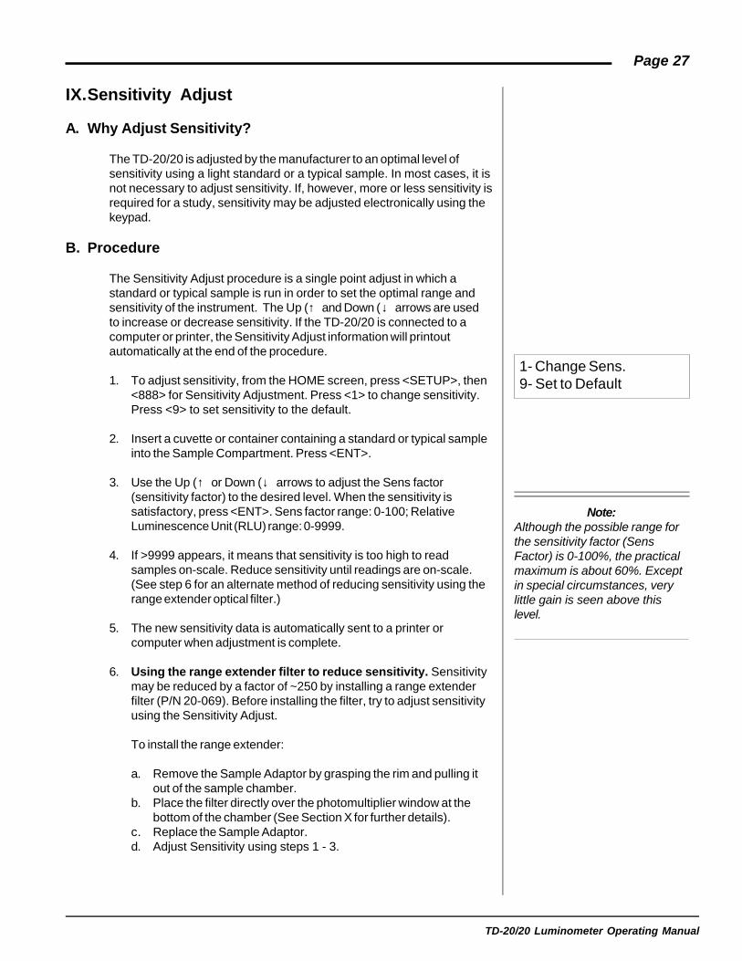
1. To adjust sensitivity, from the HOME screen, press <SETUP>, then<888> for Sensitivity Adjustment. Press <1> to change sensitivity.Press <9> to set sensitivity to the default.
2. Insert a cuvette or container containing a standard or typical sampleinto the Sample Compartment. Press <ENT>.
3. Use the Up (↑) or Down (↓) arrows to adjust the Sens factor(sensitivity factor) to the desired level. When the sensitivity issatisfactory, press <ENT>. Sens factor range: 0-100; RelativeLuminescence Unit (RLU) range: 0-9999.
4. If >9999 appears, it means that sensitivity is too high to readsamples on-scale. Reduce sensitivity until readings are on-scale.(See step 6 for an alternate method of reducing sensitivity using therange extender optical filter.)
5. The new sensitivity data is automatically sent to a printer orcomputer when adjustment is complete.
6. Using the range extender filter to reduce sensitivity. Sensitivitymay be reduced by a factor of ~250 by installing a range extenderfilter (P/N 20-069). Before installing the filter, try to adjust sensitivityusing the Sensitivity Adjust.
To install the range extender:
a. Remove the Sample Adaptor by grasping the rim and pulling itout of the sample chamber.
b. Place the filter directly over the photomultiplier window at thebottom of the chamber (See Section X for further details).
c. Replace the Sample Adaptor.d. Adjust Sensitivity using steps 1 - 3.
1- Change Sens.9- Set to Default
Note:Although the possible range forthe sensitivity factor (SensFactor) is 0-100%, the practicalmaximum is about 60%. Exceptin special circumstances, verylittle gain is seen above thislevel.

TD-20/20 Luminometer Operating Manual
Page 28
C. To View or Print the Last Sensitivity Adjust
1. To view the most recent Sensitivity Adjust data set, press <SETUP>from the HOME screen, then <9>. The Sensitivity Adjust sample/standard value, the RLU value as set on the “Sens factor” screen, will bedisplayed. Press <HOME> to return to the HOME screen. TheSensitivity Adjust stored consists of the sample value only, expressed inraw luminescence units (RLU), as run during the most recent sensitivityadjust.
2. To print the most recent Sensitivity Adjust data set, from the HOMEScreen, press <SETUP> to reach the Setup/Mode screen. Then press<SETUP> to send the current Sensitivity Adjust information to a printeror computer.
D. To Abort the Sensitivity Adjust
To abort the Sensitivity Adjust, press <ESC> at any time during theSensitivity Adjust sequence. Press <1> to abort or <ESC> to resume. Theprevious Sensitivity Adjust will be maintained if the sequence is aborted.
TD-20/20 Luminometer Operating Manual
Page 29
X. Range Extender (Optional)
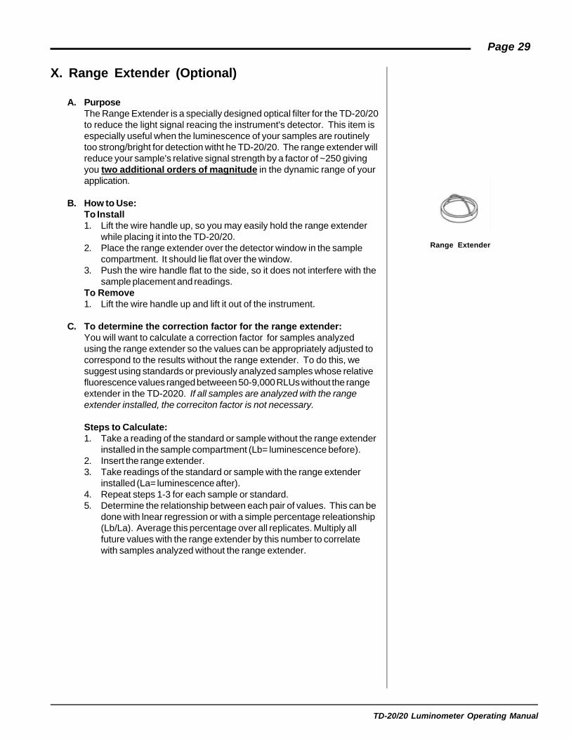
A. PurposeThe Range Extender is a specially designed optical filter for the TD-20/20to reduce the light signal reacing the instrument's detector. This item isespecially useful when the luminescence of your samples are routinelytoo strong/bright for detection witht he TD-20/20. The range extender willreduce your sample's relative signal strength by a factor of ~250 givingyou two additional orders of magnitude in the dynamic range of yourapplication.
B. How to Use:To Install1. Lift the wire handle up, so you may easily hold the range extender
while placing it into the TD-20/20.2. Place the range extender over the detector window in the sample
compartment. It should lie flat over the window.3. Push the wire handle flat to the side, so it does not interfere with the
sample placement and readings.To Remove1. Lift the wire handle up and lift it out of the instrument.
C. To determine the correction factor for the range extender:You will want to calculate a correction factor for samples analyzedusing the range extender so the values can be appropriately adjusted tocorrespond to the results without the range extender. To do this, wesuggest using standards or previously analyzed samples whose relativefluorescence values ranged betweeen 50-9,000 RLUs without the rangeextender in the TD-2020. If all samples are analyzed with the rangeextender installed, the correciton factor is not necessary.
Steps to Calculate:1. Take a reading of the standard or sample without the range extender
installed in the sample compartment (Lb= luminescence before).2. Insert the range extender.3. Take readings of the standard or sample with the range extender
installed (La= luminescence after).4. Repeat steps 1-3 for each sample or standard.5. Determine the relationship between each pair of values. This can be
done with lnear regression or with a simple percentage releationship(Lb/La). Average this percentage over all replicates. Multiply allfuture values with the range extender by this number to correlatewith samples analyzed without the range extender.
Range Extender

TD-20/20 Luminometer Operating Manual
Page 30
APPENDIX 1The Printout
A. Printout Capability with a Printer or Computer
To use this function with a printer
1. Connect the TD-20/20 to a serial printer via the RS-232 port on the backof the instrument. If you ordered a printer from Turner Designs, theappropriate serial cable is included with the printer.
2. Press <GO> from the HOME screen to initiate the Integration sequence.When the sequence is finished, the readout will be sent to the printer.
To use this function with a computer
1. Connect the TD-20/20 to your computer via the RS-232 port on the backof the instrument. Use the DB9 serial cable included with yourinstrument.
2. The TD-20/20 signal is in ASCII format so you can use variouscommunications programs to import data to your computer. On yourcomputer, run the communications program you have chosen. For astep-by-step procedure using Windows™ 95 HyperTerminal, seeAppendix 2. For instructions on using the Spreadsheet InterfaceSoftware, see Appendix 3.
3. Press <GO> from the HOME screen to initiate the Integration sequence.When the sequence is finished, the readout will be sent to the computerwith an index number.
B. Sample Reading with a Printer or Computer
At the end of a sample measurement, the TD-20/20 sends out a samplenumber index (1 - 999) and the reading of the sample in “RLU” (RelativeLuminescence Units) in ASCII format.The sample number index can be reset to 1 via
1. Using the Reset Sample index command in the firmware.See Section VIII for details.
2. Rebooting the instrument3. Changing the sensitivity4. Changing the Blank Subract Value5. Changing the Mode (STD and/or DLR)
An example of the indexing feature is illustrated by the left column in thesample printout below where only 1 replicate is selected (for example only):
Turner Designs: TD-20/20 LuminometerVer. 2020-1F 0302
Delay Time: (sec) 1Integrate Time: (sec) 4Number of Replicates: 10Sensitivity Level %: 45.2Standard Reading: 101.391

TD-20/20 Luminometer Operating Manual
Page 31
Injection Volume #1: (ul) 0Injection Volume #2: (ul) 0Blank: 0.027Mode: STDSamples:
1. 1.3462. 2.3453. 3.4564. 4.758
When the user sets the instrument to run replicates, the printout will indicatethe replicate with an “r” following the sample index number. When allreplicates have been run, the TD-20/20 will calculate and printout the averageof the replicate sample readings, the standard deviation (STD. DEV.), andthe “%CV” for the samples (see the formula below). Sample printout withreplicates (for example only):
Samples:1. r 1 1.346
r 2 1.446r 3 1.456
Avg = 1.416%CV = 4.296Std. Dev = 0.061
2. r 1 4.758r 2 4.658r 3 4.858
Avg = 4.758%CV = 2.102Std. Dev = 0.100
%CV (percent coefficient of variance) formula:
%CV = STD DEV (replicates) x 100Average (replicates)
The %CV depends on what is being measured; a lower number is preferred.
Refer to Section III for definitions of Delay Time, Integrate Time, andReplicates. Refer to Section IX for an explanation of Sens factor and Std/Sample setting.
See Section V for examples of the Data Stream print out.

TD-20/20 Luminometer Operating Manual
Page 32
APPENDIX 2Data Collection
You can use various communications software programs to import data to yourcomputer. The signal is sent from the TD-20/20 in ASCII format. You may usethe Spreadsheet Interface Software for data collection directly to Excel (SeeAppendix 3). Complete instructions are included with the software. To useWindow's '95 (or later) HyperTerminal program to import data from the TD-20/20:
1. Connect the 9-pin connector that extends from the TD-20/20 to the serialcommunications port of your computer (COM1 or COM2) using a 9-pin serialcable. You may need a 9-to-25 pin serial adaptor. Obtain this at your localcomputer store.
2. In Window's OS, locate the HyperTerminal program in the Accessoriesdirectory and double-click on the icon to open it.
3. Give the New Connection a name such as TD2020.
4. In the Phone Number window, choose Direct to COM 1 or Direct to COM 2depending on which COM Port that the instrument is connected to. (Thiscan be the hardest part of the procedure. Different computer manufacturersuse different conventions.)
5. Set the Port Settings to the following parameters : Bits per second: 9600,Data Bits: 8, Parity: none, Stop Bits: 1, Flow Control: Xon/Xoff.
6. Save the Connection by choosing the File menu and selecting Save.
7. To store the data to a file, choose the Transfer menu and select Capture.Give the captured file a name.
8. Acquire your data.
9. Stop the Capture when you are done by selecting the Transfer menu, andthen by selecting Capture/Stop.
10. Access your data using Excel, Word, or other programs by opening the fileyou saved in step 7.

TD-20/20 Luminometer Operating Manual
Page 33
APPENDIX 3Spreadsheet Interface Instructions
A. Introduction
These instructions are designed to introduce you to the TD-20/20Spreadsheet Interface Software. The software allows you to capture datadirectly into an MS Excel spreadsheet on your PC.
B. Materials Required
l TD-20/20 Luminometerl Spreadsheet Interface Software CDl RS-232 Cable & Serial Adaptorl Operating Manuall PC loaded with Windows '95 or higher (The computer should have at least one serial port available to connect to the luminometer)l MS Excel 5.0 or higher
C. Software Installation Instructions
Insert the CD into the CDROM drive of your PC. Use the "WindowsExplorer" program or "Run" command on your computer to run SETUP.EXEon the CD. This will initiate the installation program. When the installation iscomplete, an icon named "Spreadsheet Interface Software" will appear onyour PC desktop and in the Programs menu.
D. Connecting the TD-20/20 to your Computer
Plug the 9-pin RS-232 cable included in the TD-20/20 accessory kit into the9-pin connector on the back of the TD-20/20. Plug the other end of the cableinto the 9-pin connector on your computer (lower right in picture). Somecomputers have the 9-pin connector occupied by a mouse. In this case, usea serial adaptor 25F/9M provided with the software. Plug the 9-pin RS-232cable into the 9-pin side of the serial adaptor and plug the 25-pin side of theserial adaptor into the computer. The location of the 25-pin male plug on thecomputer is located next to the mouse connection and on the same PCboard (lower left in picture). Do not plug into the 25-pin female connection onyour PC, since this is usually the parallel port. (upper connector in picture).
E. Starting the Program
Click on the Spreadsheet Interface Software icon. The program will start andyou should be able to see the software start-up screen displayed in Figure 1.
E. Selecting the COM port
The default port for instrument-computer connection is COM 1. If youconnected the RS-232 cable to a different port, click on a button to the rightof COM 1 (Figure 1). The COM port selection screen will appear (Figure 2).
On COM port selection screen, select the port corresponding to the RS-232connection.
Parallel Connector (25-pinFemale). DO NOT USE.
25-pin MaleConnector. Useif 9-pin maleconnector(right) isoccupied by themouse.
9-pin Maleconnector.
Backside of the Computer

TD-20/20 Luminometer Operating Manual
Page 34
Click this buttonto change theCOM Port
Click this buttonto choose MSEXCEL Macro.
Click the "Start"button to startMS EXCEL
Figure 2
If the indicator light next to "COM 1" symbol is red (Figure 1), then thecurrent COM port is not correct. Select another COM port and click on the"Start" button until the indicator light is green.
G. AQUIRING DATA
If the correct COM port is selected, clicking on the "Start" button willsuccessfully initiate the program and launch MS EXCEL. The indicator lightnext to MS Excel on the Start-up screen (see Figure 1) will be green. Youare now ready to acquire data. Check the data output mode on the TD-20/20by pressing <7> from the HOME screen on the instrument. If <NO> isselected, data will be exported after the sample run. If <YES> is selected,data will be exported at a rate of 5 times per second during the sample run.Press <GO> on the TD-20/20, and the data will appear in MS Excelaccording to the data output mode selected on the instrument.
If the indicator light next to MS is red, it means that the sofware cannot findthe MS Excel directory. Click on the "Stop" button on the start-up screen.Launch MS Excel on your PC, then click on the "Start" button on the start-up screen.
H. Troubleshooting
Windows has a communications program called HyperTerminal included inevery installation that can help you troubleshoot problems. When bothindicator lights (next to COM1 and MS Excel) are green yet no data appearin MS Excel, follow steps A through G. This program is located in the“Accessories” directory in Windows ’95.
1. Close Spreadsheet Interface Software2. Open HyperTerminal.3. Make a New Connection.4. Give the New Connection a name.5. Choose the COM Port that the instrument is connected to. (Choose the
same COM port as selected in the Spreadsheet Interface software.)
6. Set the following parameters :Baud Rate: 9600Data Bits: 8Parity: noneStop Bits: 1Flow Control: Xon/Xoff
7. Press <GO> on the TD-20/20 keypad.
If data appears here but did not appear when running the SpreadsheetInterface Software, please contact our technical support team at408/ 749-0994 or Toll-Free 877/ 316-8049 (US & Canada).
If no data appears, then you most likely have a problem withLoose or damaged cableWrong COM port selectedCOM port occupied with other software program
Figure 1: "SpreadsheetInterface Software"Start-up Screen.
IndicatorLights

TD-20/20 Luminometer Operating Manual
Page 35
I. Pause, Stop, & Close
To pause the data collection without ending the program, click on the“Pause” button. Click on the same button, which will now say “Resume”, torestart data collection.
To stop the data collection without shutting down the program, click on the“Stop” button. The program will now be inactive until you close the MS Excelspreadsheet and click on the “Start” button. Clicking on “Start” buttonwithout closing the MS Excel spreadsheet will result in a red light next toMS EXCEL.
To shut down the program, click on the “Close” button.
J. High Level Functions
Spreadsheet Interface software has the ability to call MS Excel macros.
The Spreadsheet Interface Software calls the MS Excel spreadsheet everytime the software is launched. You can store customized MS EXCELmacros in this spreadsheet and have the program call these macros afterdata acquisition is complete. Examples of such macros include plottingdata, performing statistical analysis of the data and others to successfullystore a macro and have the Spreadsheet Interface Software run the macro.The following procedure should be followed:
1. Record the macro in Excel.2. Save the macro in C:\Program Files\Spreadsheet Interface Software3. Click on the button to the right of the MS Excel in the Spreadsheet
Interface Software start-up screen. The “EXCEL configuration” screenwill appear (Figure 3). Check the "Run Excel Macro" box, and enter thename of the macro.
4. Click on “Start” button and acquire data from the TD-20/20.5. Click on “Stop” button.
The “Stop” command executes the MS EXCEL macro you recorded.
K. Data Format
The data aquired from the TD-20/20 Luminometer can be presented in twodifferent formats in MS Excel.
Real Time Data:
The measurements for each sample appear in separate columns.
Row 1: Time of day in decimal hours (e.g. 17.1572 is 5:09:25 pm)Row 2: Blank value subtracted from the measurement.Row 3: Empty.Row 4+: Real time data. Measurements are made every 0.2 seconds.
The data shows both the delay and integration data. The totalnumber of data points displayed is equal to the sum of the delayand integration times, in seconds, multiplied by 5.
Last Row: "aborted"
Figure 3. Excel Configuration Screen

TD-20/20 Luminometer Operating Manual
Page 36
The setup parameters can be transferred to the spreadheet at any time bypressing the <SETUP> key twice from the luminometer's HOME screen.These parameters are displayed in columns G and J.
Integrated Data
Integrated data are displayed in rows. Each new measurement will bedisplayed below the previous one. This format is identical to that presentedin Appendix 1, section B.
Setup Parameters can be transferred to the spreadsheet by pressing the<SETUP> button twice on the luminometer's HOME screen.
The sample number or "index" appears in column A. Integratedmeasurement appears in column B.

TD-20/20 Luminometer Operating Manual
Page 37
APPENDIX 4Glossary
Accuracy The degree to which a measured result approximatesthe true value of the quantity being measured. This valueis usually expressed as a percent.
Analyte The substance you wish to measure.
Sensitivity Adjust Adjusting the sensitivity of the instrument to the stan-dard and samples to be read.
Dark Current A small amount of current flows in a photomultiplier tubeeven when the tube is operated in a completely darkstate. This output is called dark current and the magni-tude is greatly dependent upon the amount of voltageapplied to the photomultiplier tube (i.e. the greater theSensitivity Factor, the larger the dark current).
Detection Limit May be used to refer to either the minimum or maxi-mum concentration that can be read. Limits are specificto the luminescent material, the Sensitivity Adjustsetting of the TD-20/20, sample volume, and distance ofsample from light detector.
Drift The change in measurement of the same sample overtime.
Luminescence The TD-20/20 Luminometer measures the concentrationof various analytes in samples of interest via lumines-cence. A luminescent substance emits light undercertain conditions, which can be detected by a photo-multiplier tube.
Integration A feature of the TD-20/20 which averages the samplereading over a user-set period of time after a user-setdelay period. When <GO> is pressed from the HOMEscreen, after the user-set delay period, the signal will besummed for a user-set integrate time, and the readingdisplayed.
Noise The amount of fluctuation in the instrument’s measure-ment due to the instrument or detector itself.
RLU Luminescence Refers to the “relative” luminescence of a substancebeing read, rather than the actual concentration. Therange of “RLU Luminescence” units of the TD-20/20is 0.001 - 9999.

TD-20/20 Luminometer Operating Manual
Page 38
Resolution Resolution is related to sensitivity, but refers to the“detail” which can be read. When the instrumentsensitivity level is high, lower concentrations can beread with ease (high resolution) but higher concentra-tions can not be read on-scale. When the sensitivity islow, higher concentrations can be read, but the detail isnot as good at low concentrations (low resolution).Reading on the HOME screen: 0.001 to 9999 (4 digitlimit).
Sens factor These terms are synonymous and are used to indicateSen % the TD-20/20 Luminometer’s sensitivity on a scale of 1
to 100.
Sens % can be found on the diagnostic screen; itreflects the instrument’s current sensitivity setting as apercentage of the maximum possible sensitivity.
Sens factor is the term used in the software duringSensitivity Adjust. The Sensitivity Factor is directlyproportional to the voltage on the photomultiplier tube.The higher the Sensitivity Factor, the greater thesensitivity (and typically, the greater the “noise”) of thereadings.
Sensitivity The basic operating level of the instrument. It is relatedto the detection limits and the resolution. The electronicsensitivity is set during Sensitivity Adjust using thekeypad. Sensitivity can be adjusted mechanically usinga neutral density optical filter. Sensitivity is also relatedto sample volume and distance from the light detector.

TD-20/20 Luminometer Operating Manual
Page 39
APPENDIX 5Alarms, Diagnostics, and Troubleshooting
A. Alarm Screen
There are alarms built into the TD-20/20 to warn of an internal instrumentmalfunction or low power.
Table 1. Alarms
Alarm Delay
High Voltage (HV Bad) 3 min.
Low Power (Low PWR) 1 min.
An alarm will be activated if the abnormal condition is in effect for a specifieddelay period. If an alarm is activated, “ALM” will blink on the HOME screen.
To see what alarm is active, from the home screen press <ESC>. Forexample, if the high voltage (HV) is outside the specified range you will see“HV Bad”. If the HV alarm is triggered (HV Bad is seen when <ESC> ispressed from the HOME screen), contact Turner Designs.
If the low power alarm is triggered, check the power at the source and thepower supply.
Refer to the Diagnostic Screens (next section) for definitions.
B. Diagnostic Screens
There are diagnostic screens which show the status of internal Luminometerfunctions. To access these screens, from the HOME screen, press <8>,then <ENT> to see the next screen in the sequence.
Definitions:
Sen %. Sen % is similar to Sens factor in the software. These terms indicatethe Luminometer’s sensitivity on a scale of 1 to 100. The Sen % is directlyproportional to the voltage on the photomultiplier tube. The higher thenumber, the greater the photomultiplier tube voltage, the greater thesensitivity (and typically, the greater the “noise”) of the readings. Sen % willdisplay the current sample reading as a percentage of the RLU reading.
RLU. The “RLU” luminescence signal output from the instrument’s lightdetector (the photomultiplier tube). This is the readout on the HOME screen.Range: 0 to 9999.
NOTE: To see the RLU luminescence for the standard/sample as set duringthe last Sensitivity Adjust, from the Setup/Mode menu, press <SETUP> toprint or send to a computer. Or, from the Sensitivity Adjust & Setup menu,press <9> and it will appear on the display.

TD-20/20 Luminometer Operating Manual
Page 40
Operation Hour (Oper). Shows how many hours the instrument hasbeen operating.
Power level. When at 100%, indicates power supply is functioningcorrectly.
B. Troubleshooting
Symptom Solution Section To See
Power switch Make sure unit is plugged in securely; Section IION, but no check power from the wall socket; Makepower sure unit's power supply is functioning.
Make sure the green LED on the powersupply is on.
Display reads Sample reading is too high for the Section IX + X>9999 instrument to read at the current
sensitivity level. Use Sensitivity Adjustto reduce sensitivity. Or, install rangeextender filter.
Low readings; Sensitivity was not adjusted adequately Section IVnot enough during Sensitivity Adjust; readjust.resolution
Large Variation If using injectors, changing the tubing and Section VIbetween and a thorough cleaning maybe requiredreplicates
Air bubbles Check tubing fittings at inlet and outlet for Section VIafter priming tightness.
Injection weak Remove affected injector suppy and output Section VIand dripping tubing. Flush with clean water in opposite
direction of flow or replace.
Injection weak Remove valves flush injector and replace Section VIand dripping valves with new units.after tubingreplacement.
Drip on injector Add reagent. Place supply tubing inlet Section VIneedle tip, into the reagent.air in line.

TD-20/20 Luminometer Operating Manual
Page 41
APPENDIX 6Error Messages and Notes
During Sensitivity Adjust, the TD-20/20 will display an error message if incorrectvalues are entered or if the readings may result in an inadequate SensitivityAdjust.
A. Invalid Input
This screen will appear when you enter a value that is outside the range forthe parameter. For example, if you enter a number greater than 100 for theDelay, you will see “Invalid Input.”
B. HOME Screen Displays >9999
If the HOME screen displays “>9999” (and the lid is closed), this means thatthe sample reading is too high for the instrument’s light detector to read atthe current level of sensitivity, i.e., sensitivity is set too high (RLU reading>9999). Reduce sensitivity using the Sensitivity Adjust procedure or dilutethe sample.
When the screen display>9999 as a sample reading, no data will betransfered to the printer or computer. The instruments expect that sample tobe adjusted and reanalyzed.
During Sensitivity Adjust, if >9999 is displayed, reduce sensitivity to obtainan on-scale reading. If sensitivity cannot be adequately reduced, install arange extender filter(P/N 20-069). See Section IX and X for further details.

TD-20/20 Luminometer Operating Manual
Page 42
APPENDIX 7Maintenance, Warranty, and Service
A. Maintenance
Try to avoid spills into the sample chamber. If there is a spill:
1. Unplug the instrument.
2. Remove the test tube or dish and the sample adaptor from theinstrument. Completely dry the sample adaptor.
3. Wipe up any moisture inside the sample chamber using a soft cloth. Donot use abrasives, solvents, or acids. Take care not to scratch, obscure,or damage the photomultiplier window at the bottom of the samplechamber.
Periodically wipe off the outside of the instrument with a damp cloth. Donot use solvents, acids, or abrasive cleaners to clean the TD-20/20.
B. Warranty
Turner Designs warrants the TD-20/20 Luminometer and accessories to befree from defects in materials and workmanship under normal use andservice for a period of one year from the time of initial purchase, with thefollowing restrictions:
1. The instrument and accessories must be installed, powered, andoperated in compliance with the directions in this TD-20/20 LuminometerOperating Manual and directions accompanying the accessories.
2. Damage incurred in shipping is not covered.
3. Damage resulting from measurement of samples found to beincompatible with the materials used in the sample system is notcovered.
4. Damage resulting from contact with corrosive materials or atmosphere isnot covered.
5. Damage from sea water and other moderately corrosive materials thatare not promptly removed from the instrument is not covered.
6. Damage caused by modification of the instrument by the customer is notcovered.
7. Failure of limited life parts, such as injector valves & tubing, is notcovered.

TD-20/20 Luminometer Operating Manual
Page 43
C. Obtaining Service
Warranty Service
To obtain service during the warranty period, the owner shall take thefollowing steps:
1. Write or call the Turner Designs service department and describe asprecisely as possible the nature of the problem.
2. Carry out minor adjustments or tests as suggested by the ServiceDepartment.
3. If proper performance is not obtained, ship the instrument, prepaid, toTurner Designs, with a statement of shipping charges. The instrumentwill be repaired and returned free of charge, along with a check to covershipping charges, for all customers in the contiguous continental UnitedStates.
For customers outside of the contiguous continental United States, andwho purchased our equipment from one of our authorized distributors,contact the distributor. If you purchased direct, contact us. We will repairthe instrument at no charge, but we will not pay for shipment,documentation, etc. These charges will be billed at cost.
NOTE! Under no conditions should the instrument or accessoriesbe returned without notice. Prior correspondence is needed:
a. To ensure that the problem is not a trivial one, easily handled in yourlaboratory, with consequent savings to everyone.
b. To specifically determine the nature of the problem, so that repaircan be rapid, with particular attention paid to the defect you noted.
Out-of-Warranty Service
Proceed exactly as for Warranty Service, above. If our service departmentcan assist you by phone or correspondence, we will be glad to, at no charge.
Repair service will be billed on a basis of time and materials. A completestatement of time spent and materials used will be supplied. Shipment toTurner Designs should be prepaid. Your bill will include return shipmentfreight charges.
Address for Shipment:Turner Designs
845 W. Maude Ave.Sunnyvale, CA 94085
TD-20/20 Luminometer Operating Manual
Page 44
APPENDIX 8Specifications and Features
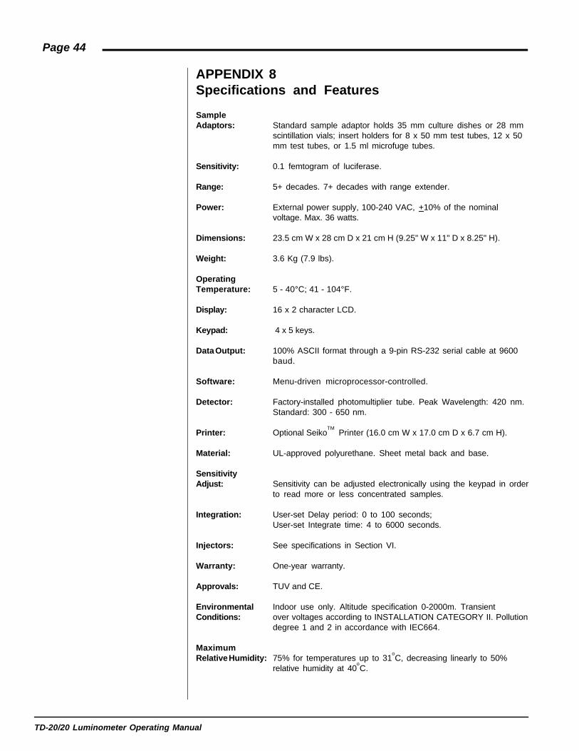
SampleAdaptors: Standard sample adaptor holds 35 mm culture dishes or 28 mm
scintillation vials; insert holders for 8 x 50 mm test tubes, 12 x 50mm test tubes, or 1.5 ml microfuge tubes.
Sensitivity: 0.1 femtogram of luciferase.
Range: 5+ decades. 7+ decades with range extender.
Power: External power supply, 100-240 VAC, +10% of the nominalvoltage. Max. 36 watts.
Dimensions: 23.5 cm W x 28 cm D x 21 cm H (9.25" W x 11" D x 8.25" H).
Weight: 3.6 Kg (7.9 lbs).
OperatingTemperature: 5 - 40°C; 41 - 104°F.
Display: 16 x 2 character LCD.
Keypad: 4 x 5 keys.
Data Output: 100% ASCII format through a 9-pin RS-232 serial cable at 9600baud.
Software: Menu-driven microprocessor-controlled.
Detector: Factory-installed photomultiplier tube. Peak Wavelength: 420 nm.Standard: 300 - 650 nm.
Printer: Optional SeikoTM
Printer (16.0 cm W x 17.0 cm D x 6.7 cm H).
Material: UL-approved polyurethane. Sheet metal back and base.
SensitivityAdjust: Sensitivity can be adjusted electronically using the keypad in order
to read more or less concentrated samples.
Integration: User-set Delay period: 0 to 100 seconds;User-set Integrate time: 4 to 6000 seconds.
Injectors: See specifications in Section VI.
Warranty: One-year warranty.
Approvals: TUV and CE.
Environmental Indoor use only. Altitude specification 0-2000m. TransientConditions: over voltages according to INSTALLATION CATEGORY II. Pollution
degree 1 and 2 in accordance with IEC664.
MaximumRelative Humidity: 75% for temperatures up to 31
oC, decreasing linearly to 50%
relative humidity at 40oC.

TD-20/20 Luminometer Operating Manual
Page 45
ANHANG 9Spezifikationen und Features
Probenhalter: Der standard Probenhalter hält 35 mm Näpfchen order 28 mmKüvetten; Halter für 8 x 50 mm Reagenzglaser, 12 x 50 mmReagenzglaser, oder 1,5 ml microfuge Gläser.
Empfindlichkeit: 0,1 femtogram Luciferase.
Massbereich: 5+ Dekaden. 7+ Dekaden mit erweitertem Messbereich.
Strom: Netzanschluß 100-240 VAC, max. 36 Watt (±10% of the nominalvoltage) ±10% der nominalen Stromspannung.
Abmessungen: 23,5 cm B x 28 cm T x 21 cm H.
Gewicht: 3,6 kg.
Arbeits-Temperatur: 5 - 40°C.
Display: 16 x 2 Stellen LCD.
Tastatur: 4 x 5 Tasten.
Datenausgabe: 100% ASCII-Format durch ein serielles 9-poliges RS232 Kabelbei 9600 Baud.
Software: Menügesteuert, Microprozessor-kontrolliert.
Detecktor: Eingebaute Photomultiplier Röhre. Spitzen Wellenlänge 420 nm.Standard 300-650 nm.
Drucker: Optional Star™ Drucker (16,0 cm B x 17,0 cm T x 6,7 cm H).
Materiel: UL-getestetes Polyurethan. Grundplatte und Rückseite ausMetall.
Empfindlichkeit-seininstellung: Die Empfindlichkeit kann auf elektonische Weise eingestellt
werden unter Benützung der Tastatur um mehr oder wenigerkonzentrierte proben zu erfassen.
Integration: Vom Benutzer eingestellte Perioden 0 bis 100 Sekunden. VomBenutzer eingestellte Integrationsperioden 4 bis 6000Sekunden.
Injectors: Benutzen Sie die Spezifikationen im Section VI.
Garantiezeit: 1 Jahr.
Geprüft: von CE, TÜV und UL.
Umbweltsbed-ingungen: Kann nicht im Freien benutzt werden. Höhenspezifikation: 0-
2000 Meter. Überspannungsspitzen laut Installationskategorie II.Verschmutzungsbereich 1 und 2 laut IEC664.

TD-20/20 Luminometer Operating Manual
Page 46
MaximalerelativeLuftfeuchtigkeit: 75% bis 30
oC, linear abnehmend bis 50% bei 40
oC.