technical manual - rice lake weighing systems · pdf filetechnical manual pn 152160 rev d. an...
TRANSCRIPT

MSI-7300Dyna-Link 2 Tension Dynamometer
Technical Manual
PN 152160 Rev D

An ISO 9001 registered company© Rice Lake Weighing Systems. All rights reserved.
Rice Lake Weighing Systems® is a registered trademark of Rice Lake Weighing Systems.
All other brand or product names within this publication are trademarks or registered trademarks of their respective companies.
All information contained within this publication is, to the best of our knowledge, complete and accurate at the time of publication. Rice Lake Weighing Systems reserves the right to
make changes to the technology, features, specifications and design of the equipment without notice.
The most current version of this publication, software, firmware and all other product updates can be found on our website:
www.ricelake.com

Contents
1.0 Introduction......................................................................................................................................11.1 Features . . . . . . . . . . . . . . . . . . . . . . . . . . . . . . . . . . . . . . . . . . . . . . . . . . . . . . . . . . . . . . . . . . . . . . . . 11.2 Safety . . . . . . . . . . . . . . . . . . . . . . . . . . . . . . . . . . . . . . . . . . . . . . . . . . . . . . . . . . . . . . . . . . . . . . . . . . 21.3 Display. . . . . . . . . . . . . . . . . . . . . . . . . . . . . . . . . . . . . . . . . . . . . . . . . . . . . . . . . . . . . . . . . . . . . . . . . . 31.4 Available Configurations. . . . . . . . . . . . . . . . . . . . . . . . . . . . . . . . . . . . . . . . . . . . . . . . . . . . . . . . . . . . . 41.5 Options . . . . . . . . . . . . . . . . . . . . . . . . . . . . . . . . . . . . . . . . . . . . . . . . . . . . . . . . . . . . . . . . . . . . . . . . . 5
2.0 Operation..........................................................................................................................................62.1 Power . . . . . . . . . . . . . . . . . . . . . . . . . . . . . . . . . . . . . . . . . . . . . . . . . . . . . . . . . . . . . . . . . . . . . . . . . . 62.2 Zero. . . . . . . . . . . . . . . . . . . . . . . . . . . . . . . . . . . . . . . . . . . . . . . . . . . . . . . . . . . . . . . . . . . . . . . . . . . . 62.3 Tare. . . . . . . . . . . . . . . . . . . . . . . . . . . . . . . . . . . . . . . . . . . . . . . . . . . . . . . . . . . . . . . . . . . . . . . . . . . . 6
2.3.1 Tare and Display the Net Tension . . . . . . . . . . . . . . . . . . . . . . . . . . . . . . . . . . . . . . . . . . . . . . . . . . . . . . . .62.3.2 Clear the Tare and Revert to Gross Tension . . . . . . . . . . . . . . . . . . . . . . . . . . . . . . . . . . . . . . . . . . . . . . . .6
3.0 Installation .......................................................................................................................................73.1 Unpacking . . . . . . . . . . . . . . . . . . . . . . . . . . . . . . . . . . . . . . . . . . . . . . . . . . . . . . . . . . . . . . . . . . . . . . . 73.2 Assembly. . . . . . . . . . . . . . . . . . . . . . . . . . . . . . . . . . . . . . . . . . . . . . . . . . . . . . . . . . . . . . . . . . . . . . . . 73.3 Battery Replacement . . . . . . . . . . . . . . . . . . . . . . . . . . . . . . . . . . . . . . . . . . . . . . . . . . . . . . . . . . . . . . . 7
4.0 Setup ................................................................................................................................................84.1 Setup Menu. . . . . . . . . . . . . . . . . . . . . . . . . . . . . . . . . . . . . . . . . . . . . . . . . . . . . . . . . . . . . . . . . . . . . . 84.2 Function Keys . . . . . . . . . . . . . . . . . . . . . . . . . . . . . . . . . . . . . . . . . . . . . . . . . . . . . . . . . . . . . . . . . . . . 9
4.2.1 Off . . . . . . . . . . . . . . . . . . . . . . . . . . . . . . . . . . . . . . . . . . . . . . . . . . . . . . . . . . . . . . . . . . . . . . . . . . . . . . .94.2.2 Test . . . . . . . . . . . . . . . . . . . . . . . . . . . . . . . . . . . . . . . . . . . . . . . . . . . . . . . . . . . . . . . . . . . . . . . . . . . . . .94.2.3 Total . . . . . . . . . . . . . . . . . . . . . . . . . . . . . . . . . . . . . . . . . . . . . . . . . . . . . . . . . . . . . . . . . . . . . . . . . . . . .104.2.4 Net / Gross . . . . . . . . . . . . . . . . . . . . . . . . . . . . . . . . . . . . . . . . . . . . . . . . . . . . . . . . . . . . . . . . . . . . . . . .104.2.5 Tare . . . . . . . . . . . . . . . . . . . . . . . . . . . . . . . . . . . . . . . . . . . . . . . . . . . . . . . . . . . . . . . . . . . . . . . . . . . . .104.2.6 Peak Hold. . . . . . . . . . . . . . . . . . . . . . . . . . . . . . . . . . . . . . . . . . . . . . . . . . . . . . . . . . . . . . . . . . . . . . . . .104.2.7 2-Units/ 5-Units . . . . . . . . . . . . . . . . . . . . . . . . . . . . . . . . . . . . . . . . . . . . . . . . . . . . . . . . . . . . . . . . . . . .114.2.8 Hi-Res . . . . . . . . . . . . . . . . . . . . . . . . . . . . . . . . . . . . . . . . . . . . . . . . . . . . . . . . . . . . . . . . . . . . . . . . . . .114.2.9 Print . . . . . . . . . . . . . . . . . . . . . . . . . . . . . . . . . . . . . . . . . . . . . . . . . . . . . . . . . . . . . . . . . . . . . . . . . . . . .11
4.3 Auto Off . . . . . . . . . . . . . . . . . . . . . . . . . . . . . . . . . . . . . . . . . . . . . . . . . . . . . . . . . . . . . . . . . . . . . . . . 114.4 Setpoints . . . . . . . . . . . . . . . . . . . . . . . . . . . . . . . . . . . . . . . . . . . . . . . . . . . . . . . . . . . . . . . . . . . . . . . 124.5 Total . . . . . . . . . . . . . . . . . . . . . . . . . . . . . . . . . . . . . . . . . . . . . . . . . . . . . . . . . . . . . . . . . . . . . . . . . . 134.6 Filter . . . . . . . . . . . . . . . . . . . . . . . . . . . . . . . . . . . . . . . . . . . . . . . . . . . . . . . . . . . . . . . . . . . . . . . . . . 144.7 Units . . . . . . . . . . . . . . . . . . . . . . . . . . . . . . . . . . . . . . . . . . . . . . . . . . . . . . . . . . . . . . . . . . . . . . . . . . 144.8 Battery Life . . . . . . . . . . . . . . . . . . . . . . . . . . . . . . . . . . . . . . . . . . . . . . . . . . . . . . . . . . . . . . . . . . . . . 15
5.0 Calibration .....................................................................................................................................165.1 Standard Calibration . . . . . . . . . . . . . . . . . . . . . . . . . . . . . . . . . . . . . . . . . . . . . . . . . . . . . . . . . . . . . . 165.2 Initial Calibration. . . . . . . . . . . . . . . . . . . . . . . . . . . . . . . . . . . . . . . . . . . . . . . . . . . . . . . . . . . . . . . . . . 17
5.2.1 Guidelines for Capacity and Resolution . . . . . . . . . . . . . . . . . . . . . . . . . . . . . . . . . . . . . . . . . . . . . . . . . . .185.3 C-Cal Calibration . . . . . . . . . . . . . . . . . . . . . . . . . . . . . . . . . . . . . . . . . . . . . . . . . . . . . . . . . . . . . . . . . 195.4 Calibration Setup Menu . . . . . . . . . . . . . . . . . . . . . . . . . . . . . . . . . . . . . . . . . . . . . . . . . . . . . . . . . . . . 20
5.4.1 Standard Menu. . . . . . . . . . . . . . . . . . . . . . . . . . . . . . . . . . . . . . . . . . . . . . . . . . . . . . . . . . . . . . . . . . . . .205.4.2 Auto Zero Maintenance (AZM). . . . . . . . . . . . . . . . . . . . . . . . . . . . . . . . . . . . . . . . . . . . . . . . . . . . . . . . . .205.4.3 Zero on Power-up (0.P-UP). . . . . . . . . . . . . . . . . . . . . . . . . . . . . . . . . . . . . . . . . . . . . . . . . . . . . . . . . . . .21
6.0 Communication..............................................................................................................................226.1 Printer . . . . . . . . . . . . . . . . . . . . . . . . . . . . . . . . . . . . . . . . . . . . . . . . . . . . . . . . . . . . . . . . . . . . . . . . . 23
6.1.1 Standard Print Strings. . . . . . . . . . . . . . . . . . . . . . . . . . . . . . . . . . . . . . . . . . . . . . . . . . . . . . . . . . . . . . . .23
Technical training seminars are available through Rice Lake Weighing Systems.
Course descriptions and dates can be viewed at www.ricelake.com/trainingor obtained by calling 715-234-9171 and asking for the training department.
© Rice Lake Weighing Systems. All rights reserved. Printed in the United States of America. Specifications subject to change without notice.
Rice Lake Weighing Systems is an ISO 9001 registered company.September 09, 2016
Contents i

6.1.2 Printer Output Setup. . . . . . . . . . . . . . . . . . . . . . . . . . . . . . . . . . . . . . . . . . . . . . . . . . . . . . . . . . . . . . . . .236.2 RF Option . . . . . . . . . . . . . . . . . . . . . . . . . . . . . . . . . . . . . . . . . . . . . . . . . . . . . . . . . . . . . . . . . . . . . . 246.3 Comm Port Hardware . . . . . . . . . . . . . . . . . . . . . . . . . . . . . . . . . . . . . . . . . . . . . . . . . . . . . . . . . . . . . 246.4 802.15.4 RF Network . . . . . . . . . . . . . . . . . . . . . . . . . . . . . . . . . . . . . . . . . . . . . . . . . . . . . . . . . . . . . 25
6.4.1 RF Network Setup . . . . . . . . . . . . . . . . . . . . . . . . . . . . . . . . . . . . . . . . . . . . . . . . . . . . . . . . . . . . . . . . . .256.5 Setup Multiple Sensor Network . . . . . . . . . . . . . . . . . . . . . . . . . . . . . . . . . . . . . . . . . . . . . . . . . . . . . . 276.6 FCC Statement (For 802.15.4 Option) . . . . . . . . . . . . . . . . . . . . . . . . . . . . . . . . . . . . . . . . . . . . . . . . . 276.7 International RF CERTS (For 802.15.4 Option) . . . . . . . . . . . . . . . . . . . . . . . . . . . . . . . . . . . . . . . . . . . 27
7.0 Maintenance and Troubleshooting ................................................................................................287.1 Troubleshooting. . . . . . . . . . . . . . . . . . . . . . . . . . . . . . . . . . . . . . . . . . . . . . . . . . . . . . . . . . . . . . . . . . 28
7.1.1 Error Codes . . . . . . . . . . . . . . . . . . . . . . . . . . . . . . . . . . . . . . . . . . . . . . . . . . . . . . . . . . . . . . . . . . . . . . .297.2 Service Counters . . . . . . . . . . . . . . . . . . . . . . . . . . . . . . . . . . . . . . . . . . . . . . . . . . . . . . . . . . . . . . . . . 297.3 Mechanical Dimensions . . . . . . . . . . . . . . . . . . . . . . . . . . . . . . . . . . . . . . . . . . . . . . . . . . . . . . . . . . . . 307.4 Standard Capacities and Resolution . . . . . . . . . . . . . . . . . . . . . . . . . . . . . . . . . . . . . . . . . . . . . . . . . . 317.5 Firmware Update Procedure . . . . . . . . . . . . . . . . . . . . . . . . . . . . . . . . . . . . . . . . . . . . . . . . . . . . . . . . 32
8.0 Specifications ................................................................................................................................33
Rice Lake continually offers web-based video training on a growing selection
of product-related topics at no cost. Visit www.ricelake.com/webinars
ii MSI-7300 Dyna-Link 2 Technical Manual

1.0 IntroductionThe Dyna-Link 2 is a reliable, accurate, easy to operate, multipurpose tension dynamometer. Designed with safety factors exceeding the industry standard, the unit is ideal for situations in which headroom is at a minimum. The unit is fully sealed for outdoor use in any weather.
A remote display option is available to further enhance the safety and usability of the Dyna-Link 2. The optional RF remote display allows tension monitoring from a distance and adds the ability to print and store data.
Manuals can viewed or downloaded from the Rice Lake Weighing Systems website at www.ricelake.comWarranty information can be found on the website at www.ricelake.com/warranties
1.1 Features• Designed to meet or exceed all U.S. and International safety and environmental standards.• Greater than 150 hours operation with two standard Alkaline C cells. Greater than 300 hours with two standard Alkaline D Cells (25000 lb/12500 kg capacities and above). Also works with off the shelf NiMH rechargeable cell batteries.
• Automatic power off conserves battery life by turning the unit off when sensing no activity for a set time.• Rugged construction throughout. IP65/NEMA Type 4 for outdoor use.• Designed for use with U.S. made Crosby shackles (optional). • Shackle holes reinforced with steel sleeves (25000 lb/12500 kg capacities and above) to reduce wear.• Shackle stops ensure ease of mounting. The stops prevent the shackles from falling to the side of the unit and are held in position for easy rigging.
• ScaleCore technology provides precision, high resolution (2500 division standard, up to 10,000 possible) 24 bit A/D conversion coupled with an advanced RISC micro-controller. ScaleCore technology provides quick and easy firmware updates, setup, calibration and backup.
• Five, 1.22'' (31 mm) LCD digits for clear tension readings from a distance. Six digits, 1'' (26 mm) on units 100,000 lb and over.
• Easy to maintain. Full digital calibration ensures reliable, repeatable measurements. Can be calibrated without test weights using C-Cal technology.
• Selectable kg/lb/tons (U.S. Short)/metric tons/kilonewtons.• Automatic or manual weight totalization for loading operations.• Easily customized for special applications. • Hi speed peak mode for stress and drop test analysis.• Two setpoints can be set for any in-range tension/weight value for operator alerts or process control. Optional audible alarm output.
• Two service counters ensure load train safety by warning the user to perform safety checks when the lift count gets high or the Dyna-Link 2 has been overloaded repeatedly. Counter 1 (Lift Count) records the number of lifts above 25% of capacity. Counter 2 (Overload Count) records the number of times the unit was overloaded.
Introduction 1

1.2 Safety
Important
CAUTION
WARNING
DANGER
Safety Signal Definitions:Indicates an imminently hazardous situation that, if not avoided, will result in death or serious injury. Includes hazards that are exposed when guards are removed.
Indicates a potentially hazardous situation that, if not avoided could result in serious injury or death. Includes hazards that are exposed when guards are removed.
Indicates a potentially hazardous situation that, if not avoided, could result in minor or moderate injury.
Indicates information about procedures that, if not observed, could result in damage to equipment or corruption to and loss of data.
General Safety
WARNING
Do not operate or work on this equipment unless this manual has been read and all instructions are understood. Failure to follow the instructions or heed the warnings could result in injury or death. Contact any Rice Lake Weighing Systems dealer for replacement manuals.
Failure to heed may result in serious injury or death.
Do not allow minors (children) or inexperienced persons to operate this unit.
Do not stand on, under or near the load being lifted as it is a potential falling hazard. Keep a safe distance.
Do not use for purposes other then weight taking or dynamic load monitoring.
Do not use any load bearing component that is worn beyond 5% of the original dimension.
Do not use the dynamometer if any of the components of the load train are cracked, deformed, or show signs of fatigue.
Do not exceed the rated load limit of the dynamometer, rigging elements or the lifting structure.
Do not allow multi-point contact with the shackles of the dynamometer unit.
Do not allow high torque on the dynamometer unless it is specifically designed for high torque.
Do not make alterations or modifications to the dynamometer or the shackles.
Do not use improperly rated or sized shackles. Use only Rice Lake recommended shackles.
Do not remove or obscure warning labels. Replace labels when worn. Contact MSI for replacement labels.
For guidelines on the safe rigging and loading of overhead scales and dynamometers, read the Crane Scale Safety and Periodic Maintenance Manual (available at www.ricelake.com).
Keep hands, feet and loose clothing away from moving parts.
There are no user serviceable parts within the Dyna-Link 2. Repairs must be performed by qualified service personnel only.
2 MSI-7300 Dyna-Link 2 Technical Manual

1.3 Display
BT
1
3 4 5 6 7 8
2
9 10
1
11 12 13
14
15 16 17 18
Figure 1-1. Dyna-Link 2 Front Panel
Table 1-1. Key Descriptions
1 F1 and F2 LEDs – indicate the function of the associated F-key is active. Example: In peak hold mode the associated LED will blink whenever a new peak reading is captured.
2 Setpoints – user programmable setpoints for early overload warnings. 3 Center-of-Zero – indicates the tension is within 1/4 d of zero.4 Standstill – indicates the tension force has settled within the motion window (usually ±1d). 5 Low Battery – displays when approximately 10% of battery life remains and blinks when automatic shutdown is imminent. 6 Peak – indicates peak hold mode. 7 Total – displays the total accumulated weight for less than five seconds.8 Net – indicates the unit is in the net tension mode. (Gross - Tare = Net).9 Metric Ton – in conjunction with the ton annunciator, indicates the unit is displaying metric tons.
When used with the total display, it is used for X1000 to allow accumulation of weight beyond the five digit display capacity. It is also used with the service counters when the number of lifts exceeds five digits.
10 Ton – illuminated alone, indicates the unit is displaying in U.S. short tons (1 ton = 2000 lb). When illuminated along with the metric ton, the unit is displaying in metric tons (1 metric ton = 1000 kg)
11 Kilogram– indicates the tension display is in kilograms.12 Kilonewton – indicates the tension display is in kilonewtons.13 Pound Key – indicates the tension display is in pounds.14 Five digit 1.22'' (31mm), sunlight visible, LCD Tension Display
Units with maximum capacity of 100,000 lb and up come with a six digit 1'' (26 mm) display.15 Power Key – turns the Dyna-Link 2 on and off. In setup mode, it returns the unit to tension display without saving settings.16 Zero – used to zero out residual tension on the link. In setup mode, it saves settings and drops back one menu level. 17 F1 Key – programmable to user functions, see Section 4.2 on page 9. 18 F2 Key – Programmable to user functions, see Section 4.2 on page 9.
Item No. Description
Introduction 3

1.4 Available Configurations
Table 1-2. Available Configurations
139162 MSI-7300 1000 Lb Final Assembly139163 MSI-7300 2500 Lb Final Assembly139164 MSI-7300 5000 Lb Final Assembly139165 MSI-7300 10000 Lb Final Assembly139166 MSI-7300 25000 Lb Final Assembly139167 MSI-7300 50000 Lb Final Assembly139168 MSI-7300 100,000 Lb Final Assembly
139441 MSI-7300RF 1000 Lb Final Assembly139442 MSI-7300RF 2500 Lb Final Assembly139443 MSI-7300RF 5000 Lb Final Assembly139444 MSI-7300RF 10000 Lb Final Assembly139445 MSI-7300RF 25000 Lb Final Assembly139446 MSI-7300RF 50000 Lb Final Assembly139447 MSI-7300RF 100000 Lb Final Assembly152794 MSI-7300RF 120,000 Lb Final Assembly152795 MSI-7300RF 180,000 Lb Final Assembly152796 MSI-7300RF 260,000 Lb Final Assembly152797 MSI-7300RF 380,000 Lb Final Assembly152798 MSI-7300RF 550,000 Lb Final Assembly
176806 MSI-7300 1,000lb F/A with Bluetooth RF176807 MSI-7300 2,500lb F/A with Bluetooth RF176808 MSI-7300 5,000lb F/A with Bluetooth RF176809 MSI-7300 10,000lb F/A with Bluetooth RF176810 MSI-7300 25,000lb F/A with Bluetooth RF176811 MSI-7300 50,000lb F/A with Bluetooth RF176812 MSI-7300 100,000lb F/A with Bluetooth RF176822 MSI-7300 120,000lb F/A with Bluetooth RF176823 MSI-7300 180,000lb F/A with Bluetooth RF176824 MSI-7300 260,000lb F/A with Bluetooth RF176825 MSI-7300 380,000lb F/A with Bluetooth RF176826 MSI-7300 550,000lb F/A with Bluetooth RF
176813 MSI-7300 1,000lb F/A with Wi-Fi RF176814 MSI-7300 2,500lb F/A with Wi-Fi RF176815 MSI-7300 5,000lb F/A with Wi-Fi RF176816 MSI-7300 10,000lb F/A with Wi-Fi RF176817 MSI-7300 25,000lb F/A with Wi-Fi RF176818 MSI-7300 50,000lb F/A with Wi-Fi RF176819 MSI-7300 100,000lb F/A with Wi-Fi RF176827 MSI-7300 120,000lb F/A with Wi-Fi RF176828 MSI-7300 180,000lb F/A with Wi-Fi RF176829 MSI-7300 260,000lb F/A with Wi-Fi RF176830 MSI-7300 380,000lb F/A with Wi-Fi RF176831 MSI-7300 550,000lb F/A with Wi-Fi RF
Part No. Description
Dyna-Link 2 Digital Tension Dynamometer
Dyna-Link 2 Digital Tension Dynamometer With Integrated RF Module For Connectivity To MSI-8000 RF Remote Display
Dyna-Link 2 Digital Tension Dynamometer With Integrated Bluetooth RF
Dyna-Link 2 Digital Tension Dynamometer With Integrated Wi-Fi RF
4 MSI-7300 Dyna-Link 2 Technical Manual

1.5 Options
Table 1-3. Available Options
151361 Shackle 175 Ton G2140Shackle Anchor 3.25 Ton Bolt TypeShackle Anchor 6.5 Ton Bolt TypeShackle Anchor 17 Ton Bolt TypeShackle Anchor 25 Ton Bolt TypeShackle Anchor 55 Ton Bolt TypeShackle, Bolt Type 160000lb (85 Ton) Pair G-2140Shackle, Bolt Type 220000lb (120 Ton) Pair G-2140Shackle, Bolt Type 350000lb (175 Ton) Pair G-2140Shackle, Bolt Type 500000lb (250 Ton) Pair G-2140MSI-8000 Remote Display RF (Requires an MSI Crane Scale or MSI-7300 equipped with a RF Modem)Final Assy Remote Display AC Power 8000HDMSI-7300 Carry Case With Foam. For Use With 1k-10k DynaLink 2 Digital Tension DynamometersMSI-7300 Carry Case with Foam for use with 1K-10K MSI-7300 and MSI-8000MSI-7300 Transport Case For Use With 25k And 50k DynaLink 2 Digital Tension DynamometersMSI-7300 Shipping Crate For Use With 100k Dyna Link 2 Digital Tension DynamometersCable Assy Heavy Duty Serial Dyna-Link 2 MSI-7300MSI-Scoreboard 4in Red 7001 RF AC PowerMSI-Scoreboard 6in Red 7001 RF AC PowerCable Assy, Serial I/O DCE D9 Sockets 8000
Part No. Description
15135715135514199215135614633683454834558345683458
139381153591139483165313145076145073139470162899162897150964
Introduction 5

6 MSI-7300 Dyna-Link 2 Technical Manual
2.0 OperationThis section includes the basic operation of the Dyna-Link 2.
2.1 Power
Turn on the Dyna-Link 2 by pressing POWER
. The LCD displays all segments for a display test and the software version number will briefly display. When is displayed, the unit is ready for use.
2.2 Zero
Press ZERO
to remove small deviations in zero when the Dyna-Link 2 is unloaded. See Section 2.3 on page 6 for zeroing (taring) package or pallet weights.
Note
• Zero works in GROSS or NET modes. • Zeroing while in NET mode will zero the gross tension causing the display to show the negative tare value. • The Dyna-Link 2 must be stable within the motion window. The unit will not zero until is displayed. The unit holds a zero request for two seconds. If the motion clears in that time, the unit will zero.
• The unit will accept a zero setting over the full range of the Dyna-Link 2. Zero settings above 4% of full capacity will be subtracted from the overall capacity. Example: If 100 lb is zeroed on a 1000 lb Dyna-Link 2, the overall capacity will reduce to 900 lb plus the allowedover-range amount.
The tension reading must be stable within the motion window for the zero function to work.
The backup memory stores the zero reading in the event of power failure.
2.3 Tare
2.3.1 Tare and Display the Net Tension1. Program an F-key to TARE. See Section 4.2.5 on page 10.
2. Press the Tare F-key. is displayed and the tension mode changes to NET. The tension reading must be stable within the motion window for the tare function to work. The backup memory stores the tare reading in the event of a power failure.
2.3.2 Clear the Tare and Revert to Gross TensionPress the Tare F-key. The NET annunciator turns off. The absence of the NET annunciator is the only indication the Dyna-Link 2 is in the GROSS tension mode.
NoteTo view the GROSS tension without clearing the tare value, program the remaining F-Key to the function NET/GROSS.
• Only positive gross tension readings can be tared.• The tension/force reading must be stable and must be on.• Setting or changing the tare has no effect on the gross zero setting.• The Dyna-Link 2 stores the tare value in non-volatile memory and is restored when power is cycled.• Taring will reduce the apparent over range of the Dyna-Link 2.
Example:
When taring 100 pounds of rigging on a 1000 lb Dyna-Link 2, the unit will overload at a net tension of 900 lb (1000-100) plus any additional allowed overload (usually about 4% or 9d).

Installation 7
3.0 Installation3.1 Unpacking When unpacking the Dyna-Link 2 from the shipping container, ensure that all assembly parts are accounted for. Check for any visible damage and immediately report any damage to Rice Lake Weighing Systems and the shipper. Retain the original shipping container for future shipping or transporting of the unit.
3.2 AssemblyTwo cotter pins and two batteries are included with the Dyna-Link 2, also required for installation are shackles and pins, they can be supplied by the customer or they can be ordered from Rice Lake Weighing Systems. See Table 1-3 on page 5.
Note
1. Slide top shackle over load cell and insert the pin. 2. Screw the shackle nut onto the pin.
It is not necessary to tighten the nut too tight. Ensure the nut is down far enough to expose the cotter pin hole.
3. Lock the shackle pin in place with the supplied cotter pin and bend the cotter pin. 4. Repeat steps 2-3 for the bottom shackle.5. Remove the battery access port cover.6. Insert the two batteries, positive end first, into the battery shaft.7. Reinstall the battery access port cover.
The Dyna-Link 2 is now ready for use.
WARNING
Note The unit will automatically start when the batteries are installed.
The Dyna-Link 2 load train is unsafe for use if the shackle pins are not properly secured with cotter pins.
3.3 Battery ReplacementDisposable BatteriesThe BT annunciator will display when the battery is getting low. When the BT annunciator starts to blink, the batteries are close to being completely drained. For maximum life, use the batteries until the system shuts off.
Rechargeable BatteriesWhen using Nickel-Metal-Hydride (NiMH) cells, it is recommended that the cells are recharged immediately after the BT annunciator starts to blink. Do not allow the batteries to discharge completely as this may compromise the recharge life of the battery.
NiMH Cells in C and D sizes have a lower capacity then the Alkaline C and D sizes. Rice Lake Weighing Systems recommends having two sets of NiMH batteries, so one set can be charging while the other is in use.
ImportantNiMH D cells are often repackaged C cells. Therefore there is no increase in battery life for Dyna-Links large enough for D cells.
The use of NiCad batteries is not recommended.
If the Dyna-Link 2 will not be used for an extended period, the batteries should be removed. A small current is used when powered off which will discharge the batteries in about six months.

4.0 SetupThis section describes parameter settings on the Dyna-Link 2.
Use the following keys for navigating through the menus when setting up the Dyna-Link 2.
1. Press and simultaneously to enter setup menu.
2. Press to scroll through the parameters or settings.
3. Press to enter a selected parameter or to save a selection and return to previous menu.
4. Press to save a selection and return to previous menu or to the weigh mode.
Press to cancel and return to weigh mode.
4.1 Setup Menu
To enter the set up menu, press and F2 at the same time.
Parameter Settings Description
Func1Func2
F1 key – configurable to listed parameters. Default is peak hold. In menu mode, functions as the enter/select key.F2 key – Configurable to listed parameters. Default is display and function test. In menu mode, functions as the scroll key.
The F-Key is disabled. Test – runs an LCD test. See Section 4.2.2 on page 9. Total – accumulation of multiple weighments. See Section 4.2.3 on page 10.
View Total – activates the total weight display followed by the number of samples. With the total displayed, press ZERO to clear.
Net/Gross – switches the display between Net and Gross modes. See Section 4.2.4 on page 10. Tare - zeros out a known weight (rigging, a packing container or pallet). See Section 4.2.5 on page 10.
Peak Hold – automatically updates the display when a higher peak weight reading is established. See Section 4.2.6 on page 10.
2 Units – toggles the force units between pounds and kilograms. See Section 4.2.7 on page 11.
5 Units – scrolls through all available units: lb, kg, Tons (US Short), Metric Tons and kiloNewtons. See Section 4.2.7 on page 11.
Hi Res – makes the MSI-7300 more sensitive to motion and movement resulting in a less stable display. Print – outputs a configured text string to the RS-232 port. See Section 4.2.9 on page 11.
A-OFF
Auto Off – sets the amount of standstill time before the Dyna-Link 2 automatically turns off. See Section 4.3 on page 11
StPt1-8 Greater Than – triggers when the tension exceeds the set value. See Section 4.4 on page 12 Less Than – triggers when the tension is less than the set value. Off – disables the setpoint parameter.
Total Total Accumulation - sets the choice for weight accumulation for a single scale.Disabled when set to off. See Section 4.5 on page 13.
Total On – a manual choice for accummulation. See Section 4.5 on page 13.
Auto Total – settings for automatic accumulations. See Section 4.5 on page 13.
Filter
Weight Filter – allows the scale to adjust to situations where there may be movement. See Section 4.6 on page 14.
Table 4-1. Setup Menu Parameters
F2
F2
F1
8 MSI-7300 Dyna-Link 2 Technical Manual

4.2 Function KeysThere are two function keys, F1 and F2 on the front panel of the Dyna-Link 2. These keys can be programmed to several different functions. See Table 4-1 on page 8 for available functions.
To assign the F-keys:
Note
1. Press and simultaneously to enter parameter setup menu. displays.
To set press again.
2. Press to enter F-key set up.
3. Press to scroll through the settings.
4. Press to select the desired choice and return to the parameter menu.
5. Press to save. displays briefly and the Dyna-Link 2 returns to the weigh mode.
This procedure also assigns the F1 & F2 keys on the optional RF remote display.
4.2.1 OffWhen the F-Key parameter is set to , there is no user key function assigned and the F-Key is disabled.
4.2.2 TestSet an F-Key as test (Section 4.2 on page 9). To run a test, press the Test F-Key and the display will automatically scroll through the following:
• Light all LCD segments and the LEDs• followed by the version number• followed by the battery level in volts• followed by counting from 00000 to 99999• followed by the c-cal value
The test can be single stepped by:
1. Press the Test F-key and then immediately press the key to stop the auto scroll.
2. Press to scroll through each step and press to view the step value.
Internal tests are also performed and if any test fails, an error code will display. See Section 7.1.1 on page 29 for a
description of all error codes. Press to stop the test at any time.
Unit lbkgTonMTonkN
Weight Units – sets the weight units displayed. See Section 4.7 on page 14.
b.LiFE
Battery Life – sets the options for standard or extended battery life. See Section 4.8 on page 15.
Parameter Settings Description
Table 4-1. Setup Menu Parameters (Continued)
F2
F2
F1
F2
F1
F2
F2 F1
Setup 9

4.2.3 Total
Note
1. Ensure the total mode has been programmed in the setup menu. If this has not been setup the F-Key assigned to TOTAL will not work.
2. Program an F-key to Total. See Section 4.2 on page 9.3. Press Total F-key to perform the total function that was set in Section 4.5 on page 13.
This feature should not be confused with the ttl.rd (Total Remote Devices) function, which will add weight from two or more load sensors.
4.2.4 Net / GrossPress the NET/GROSS F-key to switch between gross and net mode. The NET/GROSS F-key only functions if a tare value has been established. The operator can switch back to gross from net without clearing the tare value. Only clearing the tare, or setting a new tare, will change the tare value held in memory.
4.2.5 TarePress the Tare F-key to tare out a known force, only positive and negative deviations from the tared force display.
In force measurement applications, tare is useful as a way to display differential force. It also increases accuracy as any initial error is removed leaving only slope error.
In scale applications, tare is typically used to zero out a known weight such as rigging, a packing container or pallet. Once zeroed, the load displays in NET tension/weight. To use tare, set an F-key to the TARE function.
• A tare value is entered by pressing the TARE F-key. • The TARE function in the Dyna-Link 2 is defined as a tare-in/tare-out operation. • The first press of the TARE F-key stores the current tension/weight as a tare value. The Dyna-Link 2
subtracts the tare value from the gross tension and changes the display to NET mode.• The next press of the TARE F-key will clear the tare value and revert the display to GROSS mode. • The optional RF remote display has a TARE key permanently available.
4.2.6 Peak HoldThe Peak Hold function uses a high speed mode of the A/D converter allowing it to capture transient tensions at a far higher rate than typical dynamometers.
Note
• Peak hold is cleared and enabled with the PeakHold F-key.• When a new peak is detected, the F-key LED will flash three times. • The accuracy of the system in peak hold mode is slightly reduced to 0.2% of capacity ± 5d.• The filter setting is turned off while in peak hold mode to ensure the fastest acquisition rate.
Example:
The Peak Hold function is useful in materials and fall tests. Common tests include Overall Breaking Strain (OB€), Breaking Force, and Cycled Breaking Strain.
Capture Peak Force1. Program an F-key to PeakHold. See Section 4.2 on page 9.
2. Prepare the test stand and test a sample.
3. Press to zero out any residual strain on the link.
4. Press the PeakHold F-key. The Pk annunciator displays.
A small jump in the reading may occur depending on the stability of the test stand.
5. Apply the test force. The PeakHold F-key LED will blink tree times for each peak it detects.6. Remove the test force and record the peak value.7. Press the PeakHold F-key to clear the peak value.8. To run a new test, confirm Pk is not displayed. Repeat steps 1 through 6.
10 MSI-7300 Dyna-Link 2 Technical Manual
4.2.7 2-Units/ 5-UnitsProgram an F-key to either 2-UNIT or 5-UNIT. See Section 4.2 on page 9.
Press the 2-UNIT F-key to switch the force units between lb and kg.
Press the 5-UNIT F-key to scroll through all available units: lb, kg, tons (U.S. short), metric tons, and kilonewtons.
4.2.8 Hi-ResProgram an F-key to Hi-Res. See Section 4.2 on page 9.
Press the HiRes F-key to display the high resolution mode. The display will stay in high resolution mode until the HiRes F-key is pressed again, or the power is cycled. While in the hi-res mode, the appropriate HiRes F-key LED will blink continuously at a slow rate.
Hi-res mode does not increase the accuracy, but allows for smaller weight increments to be displayed.
Use Tare or to zero out any initial error. Hi-Res mode will make the Dyna-Link 2 more sensitive to motion and movement resulting in a less stable display. When Hi-Res is on, the filter is automatically set to the Hi-1 setting (if Hi-2 is already set, then the filter is not changed). This will have a small effect on settling time. When Hi-Res is turned off, the filter setting resets to the previous filter setting.
4.2.9 PrintProgram an F-key to Print. See Section 4.2 on page 9.
Press the Print F-key to output a configured text string to the RS-232 port on the base of the unit.
If a Print F-key is programmed and the print setup is configured as continuous, then the Print F-key is used for Start Print/Stop Print. See Section 6.3 on page 24 for more details on data output.
The print function is always available on the optional RF remote display, so it is not necessary to program a Print F-key if print outputs will be triggered from the remote.
If the RF remote display option is installed, the Dyna-Link 2 built in comm port is used only for hard-wire connections to the RF remote display or firmware updates.
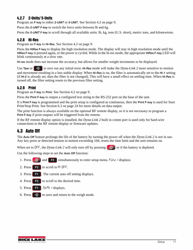
4.3 Auto Off The Auto Off feature prolongs the life of the battery by turning the power off when the Dyna-Link 2 is not in use. Any key press or detected tension in motion exceeding 10d, resets the time limit and the unit remains on.
When set to , the Dyna-Link 2 will only turn off by pressing or if the battery is depleted.
Use the following steps to set the Auto Off function:
1. Press and simultaneously to enter setup menu. displays.
2. Press to scroll to .
3. Press . The current auto off setting displays.
4. Press to scroll to the desired time.
5. Press . displays.
6. Press to save and return to the weigh mode.
F2
F2
F1
F2
F1
Setup 11

4.4 SetpointsThe Dyna-Link 2 supports two setpoints. Common uses of set points are for warnings or process control. The unit comes standard with two red LED outputs for a triggered set point. There is an audible output option that is triggered by setpoint 1.
Table 4-2. Setpoint Parameters
Setpoint is not set.
Greater Than – will trigger the setpoint when the tension exceeds the value
Less Than – will trigger the setpoint when the tension is less then the value
Net/Gross – responds to the tension on the display, net or gross weight.
Gross – responds to gross tension regardless of the display mode.
Total – responds to the totaled weight.
Total Count – responds to the total count (number of samples).
Lift Counter – counts the total number of lifts where the weight exceeded capacity by more than 25%.
To setup a setpoint:
1. Press and simultaneously to enter setup menu. displays.
2. Press to scroll to .
3. Press . The current setting displays.
4. Press to scroll to the desired setpoint mode. See Table 4-2.
5. Press to enter the setpoint mode.
6. Press to scroll to the type of tension or weight value the setpoint should be assigned.
7. Press to enter the tension or weight value.
8. Enter the number by:
• Pressing to move the cursor position and change the number.
• With the desired number displayed, press to save the number.
• Press to move the cursor to the next position.
• To enter a decimal point, press , the decimal point will be entered after last number displayed.
• To correct a number, press to go back to numbered that needs to be corrected.
9. When the weight is displayed, press to save and return to previous menu.
10.Press to save and return to the weigh mode.
Parameter Description
Selections for Greater Than and Less Than
F2
F2
F1
F2
F1
F2
F1
F2
F1
F2
F1
12 MSI-7300 Dyna-Link 2 Technical Manual

4.5 Total For the accumulation of multiple weighments, the Total function uses the displayed load, so gross and net readings can be added into the same total.
There are four modes of totalizing, a manual and three auto modes.
All modes require that the weight on the scale return below 0.5% (relative to full scale) of Gross Zero or Net Zero before the next weighment can be added. Applied weight must be ≥1% of full scale above Gross Zero or Net Zero before it can be totaled.
Manual TotalManual Total () adds a current weight to a previously accumulated value manually. To add weight to the total it must be greater than 1% of capacity and not yet totaled. This assures that a weight on the scale is only added to the total once.
Note
1. Program a F-key to . See Section 4.2 on page 9.
2. With the weight to be added on the scale, press F-Total. The acknowledge LED blinks to indicate the weight was accepted and the TOTAL annunciator lights. Then the total weight is displayed for five seconds and the number of samples is displayed for two seconds.
3. Repeat steps 1 & 2 until all weight samples have been added.
Total Mode will not function while the scale is in motion, ensure is on. If the system fails to achieve stable readings, increase the filter setting or increase the size of the scale division (d) in the Init Cal procedure.
The F-Total functions as View Total only until the 1% threshold is exceeded to allow the addition to the total value.
Auto TotalThis mode has three variations which are programmed in the Setup menu.
Program an F-key to AUTO TOTAL, it functions as Auto Total On / Auto Total Off. See Section 4.2 on page 9.
Table 4-3. Auto Load Selections
Auto Load – ensures any settled load above the Rise Above threshold will be automatically totaled. The scale must fall below the Drop Below threshold before the next total is allowed.
Auto Last – takes the last settled weight to auto total with. The total occurs only once the scale goes below the threshold. This allows the load to be adjusted without a total occurring. Once the load is removed, the scale uses the last settled reading for total.
Auto High – uses the highest settled reading. This is useful for loads that can’t be removed all at once.
To set total Mode:
1. Press and simultaneously to enter setup menu. displays.
2. Press to scroll to Total.
3. Press to enter the total mode. The current total mode will display.
4. Press to scroll through the available parameters.
5. When the desired setting is displayed, press . is displayed
6. Press to save and return to the weigh mode.
Reset Total Load
To reset the total load to zero, press Fx-Total again and while the total load is being displayed, quickly press .
Setpoint Description
F2
F2
F1
F2
F1
Setup 13

4.6 FilterChanging the filter settings allows the Dyna-Link 2 to adjust to situations where there is a lot of movement in the lift or the crane structure. If the reading is not stable, it can often be improved by increasing the filter setting. Settling time will be longer as the filter setting is increased. The Dyna-Link 2 employs algorithms that speed up large tension changes while still controlling vibration even with higher filter settings.
Table 4-4. Filter Parameters
Disables filtering function
Low Filter
High Filter
Very High Filter
To set the filter mode:
1. Press and simultaneously to enter setup menu. displays.
2. Press to scroll to .
3. Press . The current filter mode displays.
4. Press to scroll through the available filters.
5. When the desired filter is displayed, press . displays.
6. Press to save and return to the weigh mode.
4.7 UnitsUnits can be changed in two ways:
• Program an F-key to or • Change the units with the setup menu using the following procedure
Table 4-5. Units
Change the units with the setup menu:
1. Press and simultaneously to enter setup menu. displays.
2. Press to scroll to .
3. Press . The current unit will display above the word .
4. Press to scroll through the units.
5. When the desired unit is displayed, press . displays.
6. Press to save and return to the weigh mode.
To set the accessible units available by an F-key, set as 2Unit (lb/kg) or 5Unit (lb/kg/short tons/metric tons/kilonewton). See Section 4.2 on page 9.
Parameter Description
Units
Pounds
Kilograms
Short Tons
Metric Tons
KiloNewtons
F2
F2
F1
F2
F1
F2
F2
F1
F2
F1
14 MSI-7300 Dyna-Link 2 Technical Manual

NoteIf the Dyna-Link 2 Calibration was originally in tons or metric tons, the 2Unit setting will switch from tons to metric tons instead of lb/kg.
4.8 Battery LifeIn Long battery life mode, the system is placed into a sleep state for several seconds at a time if there is no change in tension. This disables the display in order to reduce power consumption and increase battery life. After several seconds, the MSI-7300 will wake up to check for any changes in tension. If there is a change in tension, the unit will stay awake. The unit will also stay awake if it is in configuration mode.
To set total Mode:
1. Press and simultaneously to enter setup menu. displays.
2. Press to scroll to .
3. Press . The current total mode will display.
4. Press to scroll through the available parameters.
5. When the desired setting is displayed, press . displays.
6. Press to save and return to the weigh mode.
F2
F2
F1
F2
F1
Setup 15

5.0 CalibrationThe Dyna-Link 2 is calibrated using standard precision test weights. It is required that the weight used is at least 10% of full capacity in order to achieve rated accuracy.
Example: Use at least a 500kg test weight to calibrate a 5000kg capacity unit.
The Dyna-Link 2 supports load cell linearization with up to four span points that can be calibrated in any order. Usually only one cal span point is necessary and is sufficient to reach rated accuracy.
When adequate test weights are not available, the Dyna-Link 2 can be calibrated using a Constant Calibration (C-Cal). To use C-Cal, the factory generated C-Cal number must be known. MSI supplies original and replacement load cells for the Dyna-Link 2 with the C-Cal value stamped on the serial number label.
There are three types of calibration:
• Standard calibration is used for maintenance and routine calibration. See Section 5.1 on page 16.• Initial calibration is used to setup both the capacity and resolution (d) of the Dyna-Link 2. It differs from
standard calibration only in the initial steps. Initial calibration is performed after a calibration reset which completely erases the calibration and parameter settings.
• C-Cal can be used if C-Cal values are known, the Dyna-Link 2 can be calibrated without weights.The calibration menu contains three items: Cal, C-Cal, and Setup. The following procedures start with entering into the Cal menu, or for an initial calibration, resetting the Dyna-Link 2 and then going to the Cal menu.
Table 5-1. Calibration Menu
Standard and initial calibration parameter. See Section 5.1 on page 16 and Section 5.2 on page 17.
C-Cal parameter. See Section 5.3 on page 19.
See Section 5.4.1 on page 20 and Section 5.4.2 on page 20.
Industrial Standard Settings
The common setting for the MSI-7300. With the Industrial standard, the unit has full range zero, access to units switching, filters, and peak hold.
Sets the scale to enable only approved features per the NTEP HB-44 rules and regulations. Access is denied to Peak Hold, and the zero range may be limited. The Filter menu is moved to the Cal Setup Menu, so filters are only accessible through the Cal Seal.
Sets the scale to enable only approved features per OIML R-76. Only kg weight units are available. The zero range is limited to 5% (-2 +3% relative to Calibrate zero). Net/Gross function is temporary. Once Net weight is established, pushing an F-key set for Net/Gross will cause a maximum 5 second display of the Gross weight. The Tare must be cleared to display Gross weight constantly. Other meteorological aspects are changed to meet R-76 requirements.
The one unit standard is exactly the same as Industrial, except unit switching is inhibited. This is useful for Metric only countries. Another use of the One Unit standard is to allow the scale to be calibrated in units other than lb or kg, since conversions are eliminated.
Auto Zero Maintenance
Set to On will cause the Dyna-Link 2 to 0 when it is powered on. Default is OFF
5.1 Standard Calibration
Note
1. Press and simultaneously to enter the calibration menu. displays.
2. Press to start calibration. displays.
3. Remove all weight from the scale.
Bottom fittings can be left on the link as long as they are always part of the load train.
Parameter Selections Description
SETUP Sub-menu
Industrial
Handbook 44
R-76
One Unit
F2
F1
16 MSI-7300 Dyna-Link 2 Technical Manual

Note
Note
Note
4. Press to set the zero calibration point. If the zero is in range, will display momentarily, then
is displayed.
If the calibration point is not within the limits, the display will read FAIL and the procedure will need to be repeated.
5. Load the link with a test weight. For highest accuracy, a test weight of 10% or more of capacity is recommended.
6. Press , the capacity flashes on the display.
7. To use a weight different of capacity, enter the number by:
• Pressing to move the cursor position and change the number.
• With the desired number displayed, press to save the number.
• Press to move the cursor to the next position.
• To enter a decimal point, press , the decimal point will be entered after last number displayed.
• To correct a number, press to go back to numbered that needs to be corrected.
8. When the weight is displayed, press to save. will display momentarily and then displays.
If the Cal Value is not within the limits, the display will read FAIL and the procedure will need to be repeated.
9. If more calibration points are desired (up to three) press and repeat steps 6-8.
10. Press to store calibration constants. will be displayed.
11. Press , the number displays, note for future reference.
12. Press to exit calibration. is displayed.
13. Press to return to weigh mode.
To cancel and return to weigh mode during calibration, press . The previous calibration will be reset.
5.2 Initial Calibration
Note
ImportantUse this procedure only if the capacity and count-by (d) needs to be modified. The initial steps of this procedure will totally erase user setups as well as any previous calibration.
1. Press and simultaneously. flashes on the display.
2. Press . displays.
3. Press to reset all calibration settings. displays.
To cancel the reset and return to the CAL menu, press .
4. Press to start initial calibration. displays.
5. Press . Use to scroll to the desired unit.
6. Press . displays.
F1
F1
F2
F1
F2
F1
F2
F1
F1
F1
F1
F1
F1 F2
F1
Calibration 17

Note
Note
7. Press . The current capacity is displayed.
8. Enter a different capacity by:
• Pressing to move the cursor position and change the number.
• With the desired number displayed, press to save the number.
• Press to move the cursor to the next position.
• To enter a decimal point, press , the decimal point will be entered after last number displayed.
• To correct a number, press to go back to the number that needs to be corrected.
9. Press . displays. The current scale division size is displayed.
10. Press to scroll through options until the desired division size is displayed.
The first selection is the standard division for the current capacity. Setting the division to a size that results in a total resolution higher than 1:5000 is not recommended for stability reasons.
11. Press . displays.
12. Follow the Standard Calibration procedure to complete calibration. See Section 5.1 on page 16 starting at step 2.
For large capacity Dyna-Link 2’s, enter the capacity in weight X1000 and push the POWER key twice. X1000 mode is indicated by the M annunciator during data entry.
For the 100,000 lb unit, enter 100 and press the POWER key twice so the M annunciator is on.
5.2.1 Guidelines for Capacity and ResolutionThe Dyna-Link 2 is subject to forces that static scales do not experience. Many bridge cranes, hoist cranes, and mobile cranes lack rigidity and tend to bounce or swing when loads are lifted. For this reason, MSI recommends that resolution is kept in the 1:2000 to 1:3000 range. Some improvement in stability can be achieved by increasing the filtering. Never program resolution that is far greater than needed. The resolution should never be set higher than 1:5000 due to temperature and noise considerations common to all strain gage based load cells.
If the Dyna-Link 2 display doesn’t stabilize, reduce the resolution and increase the filtering.
The tension must be stable for certain features to work:
• ZERO tension must be stable to be zeroed. • TARE tension must be stable to be tared. • TOTAL tension must be stable to be added to the total registers.
One way to improve the stability is to increase the filtering, at the risk of increasing settling time.
The other is to increase the ‘d’ (reduce resolution).
The third way is to increase the motion window. The Dyna-Link 2 defaults to ±1d as a motion window. It can be changed at MSI to a higher value if desired. Often ±3 d is chosen for bridge cranes as these tend to have a lot of bounce to them. This of course carries an accuracy penalty adding ±3 d to the total accuracy of the Dyna-Link 2 if the zero or tare operation happens to capture the tension in a valley or peak.
Setting capacity is dictated primarily by the capability of the load cell. The Dyna-Link 2 is available in a variety of capacities. Never set the capacity of the Dyna-Link 2 higher than the rating of the load cell. Due to the excellent linearity of the Link load cell, it is acceptable to set lower capacities to better match the crane the Dyna-Link 2 is used on. For example, if the hoist is rated for 9000 lb, a 10000 lb capacity Dyna-Link 2 can be used and the capacity reset to 9000 lb so that the Dyna-Link 2 will indicate overload at 9000 lb instead of 100000 lb. Derating as much as 50% of the capacity is usually acceptable, but the Dyna-Link 2 may be less stable if the ‘d’ is decreased (resolution increased).
NoteThe capacity of all the Dyna-Link 2 systems is rated approximately 20% higher than the rated capacity in pounds. This is to allow the kg capacity to be exactly 1/2 the number of the pounds capacity.
F1
F2
F1
F2
F1
F2
F1
18 MSI-7300 Dyna-Link 2 Technical Manual

5.3 C-Cal CalibrationWhen adequate test weights are not available, the Dyna-Link 2 can be calibrated using a cal number calibration which is referred to as C-Cal. To use C-Cal, a factory generated C-Cal number must be known. Replacement load cells for the Dyna-Link 2 have the C-Cal value stamped on the serial number label. When a calibration is performed with test weights, a new C-Cal is generated.
Note
Note
ImportantThe C-Cal number must be known prior to starting this procedure. For a Dyna-Link 2, with its original load cell, this number is printed on the Calibration Record, the serial number tag. C-Calibration reduces slightly the absolute accuracy of the system and is intended for non-critical use only. For highest accuracy, calibrate the Dyna-Link 2 with precision test weights.
1. Press and simultaneously to enter the calibration menu. is displayed.
2. Press to .
3. Press to start the calibration procedure. displays.
Bottom fittings on the link can be left on as long as they are always part of the load train.
4. Remove all weight from the scale.
5. Press to set the zero calibration point. If the zero is in range, is displayed, followed by .
6. Press , the last known value is displayed.
7. Press if the display value is correct go to step 8.If value is not correct, enter the value as follows:
• Press to move the cursor position and change the number.
• With the desired number displayed, press to save the number.
• Press to move the cursor to the next position.
• To enter a decimal point, press , the decimal point will be entered after last number displayed.
• To correct a number, press to go back to numbered that needs to be corrected.
8. Press when the value is correct. If the value is within acceptable range, is displayed
briefly, followed by .
Multiple C-CAL span points are possible when using the ScaleCore Connect program.
9. Press twice to exit and save the new calibration. displays briefly and the Dyna-Link 2
returns to the weigh mode.
F2
F2
F1
F1
F1
F1
F2
F1
F2
F1
Calibration 19

5.4 Calibration Setup MenuThe calibration setup menu contains the Standard Menu and the Auto Zero Maintenance Menu. Additional menus will display depending on the main setup menu when Legal-for-Trade settings are used.
Industrial Standard Settings
The common setting for the MSI-7300. With the Industrial standard, the unit has full range zero, access to units switching, filters, and peak hold.
Sets the scale to enable only approved features per the NTEP HB-44 rules and regulations. Access is denied to Peak Hold, and the zero range may be limited. The Filter menu is moved to the Cal Setup Menu, so filters are only accessible through the Cal Seal.
Sets the scale to enable only approved features per OIML R-76. Only kg weight units are available. The zero range is limited to 5% (-2 +3% relative to Calibrate zero). Net/Gross function is temporary. Once Net weight is established, pushing an F-key set for Net/Gross will cause a maximum 5 second display of the Gross weight. The Tare must be cleared to display Gross weight constantly. Other meteorological aspects are changed to meet R-76 requirements.
The one unit standard is exactly the same as Industrial, except unit switching is inhibited. This is useful for Metric only countries. Another use of the One Unit standard is to allow the scale to be calibrated in units other than lb or kg, since conversions are eliminated.
Auto Zero Maintenance
Set to On will cause the Dyna-Link 2 to 0 when it is powered on. Default is OFF
5.4.1 Standard MenuUse the following information and steps to set up a Legal-for-Trade standard setting.
1. Press and simultaneously to enter the calibration menu. is displayed.
2. Press to scroll to Setup.
3. Press . is displayed.
4. Press . The current standard setting is displayed.
5. Press to scroll to the desired standard.
6. Press to select the desired standard.
7. Press twice to store all changes and exit setup. displays briefly and returns to the weigh mode.
5.4.2 Auto Zero Maintenance (AZM)The Dyna-Link 2 employs an auto zeroing maintenance mechanism to adjust the zero reading to the center-of-zero, which is defined as the tension reading is within ¼ d of zero. AZM continuously adjusts zero to maintain center-of-zero. It is recommended that AZM is set to on to maintain the highest accuracy. There are circumstances when the AZM should be turned off; for example, when minor variations of tension occur while picking up Dyna-Link 2 attachments and the variations fall within the AZM capture window. The AZM capture window (usually 1 d) and capture time (usually eight seconds) can be adjusted by MSI to meet custom requirements.
1. Press and simultaneously to enter the calibration menu. is displayed.
2. Press to scroll to .
3. Press . displays.
4. Press to scroll to .
Parameter Selections Description
Industrial
Handbook 44
R-76
One Unit
F2
F2
F1
F1
F2
F1
F2
F2
F1
F2
20 MSI-7300 Dyna-Link 2 Technical Manual

5. Press . The current setting displays.
6. Press to scroll to or .
7. Press to select desired setting. displays.
8. Press twice to store settings. displays briefly and the Dyna-Link 2 returns to the weigh mode.
5.4.3 Zero on Power-up (0.P-UP)Set to on to perform a zero each time the Dyna-Link 2 is time the powered on.
1. Press and simultaneously to enter the calibration menu. is displayed.
2. Press to scroll to .
3. Press . displays.
4. Press to scroll to .
5. Press . The current setting displays.
6. Press to scroll to or .
7. Press to select desired setting. displays.
8. Press twice to store settings. displays briefly and the Dyna-Link 2 returns to the weigh mode.
F1
F2
F1
F2
F2
F1
F2
F1
F2
F1
Calibration 21

6.0 Communication The Dyna-Link 2 can communicate with peripheral devices using RS-232 or 802.15.4 wireless. Only one communications type can exist at a time. The RS-232 port located on the bottom side of the Dyna-Link 2 can be used for setup and calibration using a computer and the ScaleCore Connect Software (available Online).
Table 6-1. Communication Menu
Setup Strings – enter a print string number
Print Control – select from paramters: – disables printing – press the assigned F-Key and one transmission of the selected string type is output – when the tension on the link is stable, one transmission will output. The tension
must return to zero to enable another print to output. – program the interval in seconds up to 65535 seconds
Output Rate Network ID – print string output rate, enter a number between 0-65635 seconds. Setting the interval to 0 will set an interval as fast as the system can go.
Enable RF – affects continuous mode only, select On or Off
Scalecore ID – range 1-254 (20-30)
RF Channel – range 12-23
Network ID – range 0 to 99999
RF Network – number of entry screens
1. To enter the communication menu on the Dyna-Link 2 press and simultaneously
2. Press to scroll through the parameters or settings.
3. Press to enter a parameter or save a selection and return to previous menu.
4. Press to save a selection and return to previous menu.
5. Press to cancel and return to weigh mode.
6. Press to save. displays briefly and the Dyna-Link 2 returns to the weigh mode.
Parameter Parameter Description
Print Print setup. See Section 6.3 on page 24.
1 = Current Wt (Wt-Unit-Mode )2 = Net Wt (Wt-Unit-Net )3 = Gross Wt (Wt-Unit-Grs )4 = Tare Wt (Wt-Unit-Tare )5 = Total Wt (Wt-Unit-Total )6 = Total Count (#Samples-TCNT )7 = Current Wt (no units or mode )8 = Reserved9 = CR-LF ()
rF Radio frequency setup. See Section 6.4 on page 25
F1 F2
F2
F1
22 MSI-7300 Dyna-Link 2 Technical Manual

6.1 PrinterThe RS-232 comm port is capable of outputting tension data. All the weight modes the Dyna-Link 2 can measure are available in user formatted form. The control mode program is what causes the Dyna-Link 2 to print.
6.1.1 Standard Print StringsThe following commands can be used to format gross, net and other print formats.
<T> Tension Data with sign if necessary<U> Units<M> Tension mode (lb/kg), which for 1 is either net or gross
<CRLF> Carriage return line feed<SP> Space
Table 6-2. Print commands
Fixed output length: 16. Leading zeros suppressed except for the least significant digit (LSD).<TTTTTTT><SP><UU><SP><MMMMM><CRLF>
2 Net TensionFixed output length:16. Leading zeros suppressed except for the LSD. <TTTTTTT><SP><UU><SP><NET><SP><SP><CRLF>
3 Gross TensionFixed output length: 16. Leading zeros suppressed except for the LSD.<TTTTTTT><SP><UU><SP><GROSS><CRLF>
4 Tare WeightFixed output length:16. Leading zeros suppressed except for the LSD.<TTTTTTT><SP><UU><SP><TARE><CRLF>
5 Total WeightFixed output length: 16. Leading zeros suppressed except for the LSD.<TTTTTTT><SP><UU><SP><TTL><CRLF>
6 Number of Samples Totaled
Fixed output length: 16. Leading zeros suppressed except for the LSD.<SP><SP><SP><SP><SP><SP><SSSSSSS><SP><T-CNT><SP><CRLF>
7 Current Weight Mode Net, Gross, Peak, etc<SP><MMMMM><CRLF>
8/9 Carriage Return/Line Feed
Used to add a space between print records. <CRLF>
Table 6-3. Print Strings
In the string number entry screen, combinations of the standard print strings may be entered. For example, to get a NET, GROSS and TARE, printout with a space between records, enter 2349.
Using the ScaleCore Connect, custom output strings are possible.
NoteScaleCore Connect programming can be found on the CD included with the product or can be downloaded from www.ricelake.com.
The serial output is configured as 9600 baud, Xon/Xoff handshaking, no hardware handshaking, 1 stop bit, no parity. Other baud rates are available by special order.
6.1.2 Printer Output Setup1. Press and simultaneously. is displayed.
2. Press . displays.
3. Press . The current print mode format number is displayed.
4. Set up a print format with one or more of the numbers of the data type required. See Table 6-3.
• Pressing to scroll to the desired number.
Command Description
String No. Print String Description
1 Current Tension
F1 F2
F1
F1
F2
Communication 23

• Press to save the number.
• Repeat until all desired numbers have been entered.
5. Press . displays.
6. Press to enter print control. The last saved control mode will display.
7. Press until the desired print control mode is displayed.
8. Press . displays. If print control mode is set to , continue with step 9. If set to , or , go to step 12.
9. Press . The current print weight is displayed.
10. Enter the desired print rate.
• Press to move the cursor position and change the number.
• With the desired number displayed, press to save the number.
• Press to move the cursor to the next position.
• To correct a number, press to go back to numbered that needs to be corrected.
11. When the desired number is displayed, press . displays.
12. Press twice to return to weigh mode.
6.2 RF OptionThe RF options are easily connected and commonly used for gathering weight data after the initial setup of the unit. For RF operation, the Dyna-Link 2 uses an 802.15.4 transceiver to communicate with the MSI-8000/8000HD RF Remote Display.
802.15.4 wireless:
• operates in the 2.4GHz ISM band and does not require the end user to obtain a license. • can coexist with other 2.4GHz systems, if caution is taken to isolate antennas at least 10' (3 m) from the
Crane Scales and MSI-8000/8000HD equipment. • Bluetooth• Wi-Fi
MSI-8000/8000HD based RF systems are peer to peer. For multiple scale connections, the MSI-8000/8000HD acts as the network coordinator.
6.3 Comm Port HardwareThe Dyna-Link 2 RS-232 comm port is used for software updates, connecting to a remote display, and for connecting to any RS-232 device.
Table 6-4. Comm Port Hardware
ConnectorM12 industrial IP67 rated. An adapter cable (P/N 503363) is required to connect the Dyna-Link 2 to a computer. This adapter cable converts the Dyna-Link 2 connector to a standard D9 serial connector.
Data Configuration The data output is fixed at 8-1-N.
Baud Rate Programmable for 300 to 230.4k baud in eight steps. The bootloader for updating software is always 38.4k baud.
Handshaking No hardware handshaking is supported XON/XOFF software handshaking is always on.
F1
F1
F1
F2
F1
F1
F2
F1
F2
F1
24 MSI-7300 Dyna-Link 2 Technical Manual

It may be necessary to disconnect the shield drain wire at the D-9 connector frame to prevent ground loops. Ground loops can cause unstable readings. In extreme cases it may be necessary to use an opto-isolated RS-232 interface.
Note
Figure 6-1. Serial Cable Schematic, DCE Configuration for Connecting to a Computer
Figure 6-2. Serial Cable Schematic, DTE Configuration for Connecting Directly to a DCE Printer
6.4 802.15.4 RF NetworkWhen equipped with the 802.15.4 option, the Dyna-Link 2 can connect with an MSI-8000/8000HD Remote Display or an 802.15.4 modem. The unit uses three numbers to connect to an 802.15.4 piconet:
Note
• ScaleCore ID – uniquely identifies each ScaleCore device in a piconet. It has a range of 0-254 and must not be duplicated within the same RF channel. For the MSI-8000/8000HD as network coordinator, Rice Lake Weighing Systems recommends a number for the Dyna-Link 2 from 0-3 if multiple units will be connected to the MSI-8000/8000HD. If a single Dyna-Link 2 is all that’s needed than any number up to 254 is acceptable.
• RF Channel – establishes the base network, all interconnected devices must match. This number must be in the range of 12-23.
• Network ID – this is a 64-bit number that all interconnected devices must match. The Dyna-Link 2 limits this number to a max of 5 digits for a range of 0 - 99999. Do not use a small number here to help avoid other 802.15.4 networks that default to a network ID of 0.
• RF Strength – transmission strength can be set from 0 to 4, default is 1. The settings effect the transmission range with zero is lowest power level and four is the highest. Power 4 will use the battery life quicker, so use the lowest number possible for reliable transmission. If maximum range is needed set the strength to four.
For all devices that interconnect, the RF channel and network ID must match. The ScaleCore ID must be unique. The Dyna-Link 2 or other MSI RF equipment that is a weight data source should be set to a ScaleCore ID of 0, then if other slave devices are added, they can be added in sequence.
6.4.1 RF Network Setup1. Press and simultaneously. is displayed.
2. Press . displays.
3. Press . is displayed.
4. Press to enter the ON/OFF setting.
F1 F2
F2
F1
F1
Communication 25

5. Press to scroll to the desired setting.
6. Press . is displayed.
7. Press . The current SCID number displays.
8. Press to scroll through the numbers and press to select the desired number.
Any value of SCID from 1 - 254 is acceptable, however, Rice Lake Weighing Systems recommends a value from 20-30.
If a wrong value is input, press to step back one digit and reenter the number.
9. When the desired number is displayed, press . displays.
10. Press . The current channel displays.
11. Press to scroll through the numbers and press to select the desired number.
Recommended RF Channel number range from 12-23.
If a wrong value is input, press to step back one digit and reenter the number.
12. When the desired number is displayed, press to save. is displayed.
13. Press . The current network ID.
14. Press to scroll through the numbers and press to select the desired number.
Any network ID numbers from 0-99999 is acceptable. Rice Lake Weighing Systems recommends a value of at least four digits to ensure that the system will not conflict with other 802.11.4 networks.
If a wrong value is input, press to step back one digit and reenter the number.
15. When the desired number is displayed, press to save. displays.
16. Press . The transmission strength is displayed.
17. Press to scroll through the numbers and press to select the desired number.
The transmission strength range is 0-4. When setting the transmission strength, use the lowest setting possi-ble to achieve the transmission required. Both the Dyna-Link 2 and the 8000 should be set at the same trans-mission strength.
18. When the desired number is displayed, press . is displayed.
19. Press twice to store settings and return to weigh mode.
F2
F1
F1
F2 F1
Note
F1
F1
F2 F1
Note
F1
F1
F2 F1
Note
F1
F1
F2 F1
Note
F1
26 MSI-7300 Dyna-Link 2 Technical Manual

6.5 Setup Multiple Sensor NetworkThe MSI-8000/8000HD Remote Display can monitor up to four load sensors. The sensors can be read individually, in pairs or summed.
5000 lbs / 2500 KGMAXIMUM CAPACITY
7300lb
5000 lbs / 2500 KGMAXIMUM CAPACITY
7300lb
SC 0 SC 1
Pair1(Sum) All
5000 lbs / 2500 KGMAXIMUM CAPACITY
7300lb
5000 lbs / 2500 KGMAXIMUM CAPACITY
7300lb
SC 0 SC 1
Pair1
5000 lbs / 2500 KGMAXIMUM CAPACITY
7300lb
SC 2
(Sum) All
5000 lbs / 2500 KGMAXIMUM CAPACITY
7300lb
5000 lbs / 2500 KGMAXIMUM CAPACITY
7300lb
SC 0 SC 1
Pair1
5000 lbs / 2500 KGMAXIMUM CAPACITY
7300lb
5000 lbs / 2500 KGMAXIMUM CAPACITY
7300lb
SC 2 SC 3
Pair2
(Sum) All
Figure 6-3. Multiple Sensor Network
Each sensor has a unique ScaleCore ID (SCID). The IDs must be consecutive, starting with 0. This is set in the sensor setup, not in the MSI-8000/8000HD. See the MSI-8000/8000HD operation manual for more information.
6.6 FCC Statement (For 802.15.4 Option)Contains FCC ID: OUR-XBEEPRO
The enclosed device complies with part 15 of the FCC rules. Operation is subject to the following two conditions: (i.) this device may not cause harmful interference and (ii.) this device must accept any interference received, including interference that may cause undesired operation.
6.7 International RF CERTS (For 802.15.4 Option)Canada Radio Cert. No.: IC: 4214A-XBEEPROAustralia & New Zealand: AS4268:3000Japan: Certificate of Radio Equipment in Japan No.: 08215111/AA/02Europe and much of Asia:
This product is compliant with the following standards and/or other normative documents:
Safety (article 3.1A) EN60950-1:2001
EMC (article 3.1b) ETSI EN 301 489-1 v1.7.1 (2007-04) In accordance with the specific requirements of ETSI EN 301 489-17 v1.2.1 (2002-08)
Spectrum (article 3.2) ETSI EN 300 328 v1.7.1 (2006-10)
Communication 27

7.0 Maintenance and Troubleshooting
7.1 TroubleshootingProblem Possible Cause Solution
Display is blank when POWER key is pressed
Discharged battery Replace cells, or if using NiMH, rechargeDefective battery ReplaceCorroded battery or battery contacts Clean contactsDefective switch or circuit board Requires authorized service
Display does not function properly or front panel keys do not function normally or Dyna-Link 2 will not turn off
Improperly loaded software Reinstall softwareFaulty circuit board Requires authorized serviceLoose connectors Requires authorized service
Dyna-Link 2 does not respond to tension changes
Out of calibration CalibrateFaulty load cell ReplaceLoad cell connector Check connector and wires
Display over ranges below 100% of capacity
Tared tension is added to load to determine overload point
Return to gross tension mode
Zero requires adjustment Rezero the Dyna-Link 2Too much tension/load has been zeroed
Rezero the Dyna-Link 2
Display drifts AZM (Auto0) is turned off Turn AZM onRapid temperature changes such as moving the Dyna-Link 2 from indoors to outdoors
Wait until the Dyna-Link 2 temperature has stabalized
Displayed tension shows larger error
Dyna-Link 2 not zeroed before load is lifted
Zero the Dyna-Link 2 with no load attached
lb/kg units causing confusion Select proper unitsRequires recalibration Recalibrate
Display reading not stable Excessive vibration in crane system Increase filtering or increase d in CalExcessive side loading Improve load train symmetryLoad cell faulty Check LC connections
Display toggles between Error and Load
Tension exceeds capacity Immediately reduce tension Faulty load cell or wiring Check LC and LC wiring
Display toggles between Error and buttn
A key is stuck or is being held down Check switches for damageEnsure that a remote is not continuously transmitting
Optional RF Remote display does not work
Units not mated See RF Remote Manual
Lo Batt is blinking Battery is low Replace (alkaline) or recharge batteriesUnit turns on, then immediately off
Battery is low Replace (alkaline) or recharge batteries
Tension will not zero System not stable Wait for standstill annunciator to turn onIncrease filtering for more stability
Zero out of range Zero range might be limited. Reduce the tension or use tare instead
Tension will not tare or total
System is not stable Wait for standstill annunciator to turn on, or if in a mechanically noisy crane, increase the filtering or reduce the size of the Dyna-Link 2 increment d. It is also possible to increase the motion window. Contact Rice Lake Weighing Systems if there is a problem getting the Dyna-Link 2 to zero, tare, or total due to stability issues.
Setpoint lights blink Setpoint is enabled and the trigger point has been reached
Disable setpoints if they are not needed
Table 7-1. Troubleshooting
28 MSI-7300 Dyna-Link 2 Technical Manual
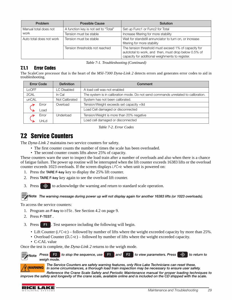
7.1.1 Error CodesThe ScaleCore processor that is the heart of the MSI-7300 Dyna-Link 2 detects errors and generates error codes to aid in troubleshooting.
Table 7-2. Error Codes
LcOFF LC Disabled A load cell was not enabled2CAL In Cal The system is in calibration mode. Do not send commands unrelated to calibration.unCAL Not Calibrated System has not been calibrated.
Error
Load
Overload Tension/Weight exceeds set capacity +9dLoad Cell damaged or disconnected
Error
UnLd
Underload Tension/Weight is more than 20% negativeLoad cell damaged or disconnected
7.2 Service CountersThe Dyna-Link 2 maintains two service counters for safety.
• The first counter counts the number of times the scale has been overloaded. • The second counter counts lifts above 25% of capacity.
These counters warn the user to inspect the load train after a number of overloads and also when there is a chance of fatigue failure. The power up routine will be interrupted when the lift counter exceeds 16383 lifts or the overload counter exceeds 1023 overloads. If the screen displays when unit is powered on:
Note
1. Press the TARE F-key key to display the 25% lift counter. 2. Press TARE F-key key again to see the overload lift counter.
3. Press to acknowledge the warning and return to standard scale operation.
The warning message during power up will not display again for another 16383 lifts (or 1023 overloads).
To access the service counters:
1. Program an F-key to . See Section 4.2 on page 9.2. Press F-TEST .
3. Press . Test sequence including the following will begin.
• Lift Counter () – followed by number of lifts where the weight exceeded capacity by more than 25%.• Overload Counter () – followed by number of lifts where the weight exceeded capacity.• C-CAL value
Once the test is complete, the Dyna-Link 2 returns to the weigh mode.
Note Press F2 to stop the sequence, use F1 and F2 to view parameters. Press to return to weigh mode.
The Service Counters are safety warning features, only Rice Lake Technicians can reset these.WARNING In some circumstances, a thorough load train inspection may be necessary to ensure user safety.
Reference the Crane Scale Safety and Periodic Maintenance manual for proper loading techniques to improve the safety and longevity of the crane scale, available online and is included on the CD shipped with the scale.
Manual total does not work
A function key is not set to “Total” Set up Func1 or Func2 for TotalTension must be stable Increase filtering for more stability
Auto total does not work Tension must be stable Wait for standstill annunciator to turn on, or increase filtering for more stability
Tension thresholds not reached The tension threshold must exceed 1% of capacity for autototal to work, and then, must drop below 0.5% of capacity for additional weighments to register.
Error Code Definition Comment
Problem Possible Cause Solution
Table 7-1. Troubleshooting (Continued)
F1
Maintenance and Troubleshooting 29

7.3
5000 lbs / 2500 KGMAXIMUM CAPACITY
7300lb
B
C = DIA.
E = LOAD CELL BODY WIDTH AT SHACKLE INTERFACE.
A
D
GF
Mechanical Dimensions
Figure 7-1. Mechanical Dimensions
Table 7-3. Mechanical Dimensions
1000 lb 8.0 in 13.53 in .75 in 5 in .99 in 1.69 in 1.75 in 4.4 lb G-2130 3.25T
500 kg 203 mm 344 mm 19 mm 127 mm 25 mm 43 mm 44.4 mm 2.0 kg
2500 lb 8.5 in 14.03 in .75 in 5 in .99 in 1.69 in 1.75 in 4.9 lb G-2130 3.25T
1250 kg 216 mm 356 mm 19 mm 127 mm 25 mm 43 mm 44.4 mm 2.2 kg
5000 lb 8.5 in 14.03 in .75 in 5 in .99 in 1.69 in 1.75 in 4.9 lb G-2130 3.25T
2500 kg 216 mm 356 mm 19 mm 127 mm 25 mm 43 mm 44.4 mm 2.2 kg
10,000 lb 8.5 in 16.14 in 1 in 5.50 in 1.35 in 2.28 in 2.34 in 7.3 lb G-2130 6.5T
5000 kg 216 mm 410 mm 25 mm 140 mm 34 mm 58 mm 59.4 mm 3.3 kg
25,000 lb 9.5 in 22.66 in 1.63 in 6.38 in 2.24 in 3.88 in 4.69 in 13 lb G-2130 17T
12,500 kg 241 mm 576 mm 41 mm 162 mm 57 mm 99 mm 119 mm 5.9 kg
50,000 lb 9.63 in 25.67 in 2 in 7.50 in 2.74 in 5.00 in 5.75 in 23 lb G-2130 25T
25,000 kg 245 mm 652 mm 51 mm 191 mm 70 mm 127 mm 146 mm 10 kg
100,000 lb 12 in 29.75 in 2.25 in 8.13 in 3.11 in 5.75 in 4.81 in 53 lb G-2140 55T
50,000 kg 305 mm 756 mm 57 mm 207 mm 79 mm 146 mm 122 mm 24 kg
Capacity A B C D E F GApprox
Shipping Wt
Shackle
30 MSI-7300 Dyna-Link 2 Technical Manual

7.4 Standard Capacities and Resolution
WARNINGThe Dyna-Link 2 has a safe mechanical overload of 200% of capacity. Overloads greater than 200% may result in physical damage to the link. The ultimate overload is rated to 500%-700% of capacity. At ultimate overload, structural failure and dropped loads may occur. Dropped loads may cause serious personal injury or death.
Note Short ton and metric ton resolutions are the same.
Table 7-4. Standard Capacities and Resolutions
1000 lb500 kg0.5 Ton4.9 kN
0.5 lb0.2 kg0.0002 T0.002 kN
2000250025002450
0.2 lb0.1 kg0.0001 T0.001 kN
5000500050004900
>>700% Alum2 C-Cells
2500 lb1250 kg1.25 ton12.25 kN
1 lb0.5 kg0.0005 T0.005 kN
2500250025002450
0.5 lb0.2 kg0.0002 T0.002 kN
5000625050004900
700% Alum2 C-Cells
5000 lb2500 kg2.5 Ton24.5 kN
2 lb1 kg0.001 T0.01 kN
2500250025002450
1 lb0.5 kg0.0005 T0.005 kN
5000500050004900
700% Alum2 C-Cells
10000 lb5000 kg5.0 Ton4.9 kN
5 lb2 kg0.002 T0.02 kN
2000250025002450
2 lb1 kg0.001 T0.01 kN
5000500050004900
700% Alum2 C-Cells
25000 lb12500 kg12.5 Ton122.5 kN
10 lb5 kg0.005 T0.05 kN
2500250025002450
5 lb2 kg0.002 T0.02 kN
5000625062506125
700% Alum2 D-Cells
50000 lb25000 kg25 Ton245 kN
20 lb10 kg0.01 T0.1 kN
2500250025002450
10 lb5 kg.005 T0.05 kN
5000500050004900
600% Alum2 D-Cells
100000 lb50000 kg50 Ton490 kN
50 lb20 kg0.02 T0.2 kN
2000250025002450
20 lb10 kg0.01 T0.1 kN
5000500050004900
550% Alum2 D-Cells
120000 lb60000 kg60 Ton588 kN
50 lb20 kg0.02 T0.2 kN
2400300030002940
20 lb10 kg0.01 T0.1 kN
6000600060005880
500% Steel2 D-Cells
180000 lb90000 kg90 Ton882 kN
100 lb50 kg0.05 T0.5 kN
1800180018001764
50 lb20 kg0.02 T0.2 kN
3600360045004410
500% Steel2 D-Cells
260000 lb130000 kg130 Ton1275 kN
100 lb50 kg0.05 T0.5 kN
2600260026002550
50 lb20 kg0.02 T0.2 kN
5200650065006375
500% Steel2 D-Cells
380000 lb190000 kg190 Ton1863 kN
200 lb100 kg0.1 T1 kN
1900190019001863
100 lb50 kg0.05 T0.5 kN
3800380038003726
500% Steel2 D-Cells
550000 lb225000 kg225 Ton2206 kN
200 lb100 kg0. 1 T1 kN
2750225025002206
100 lb50 kg0.05 T0.5 kN
5500450050004412
440% Steel3 D-Cells
CapacityStd‘d’
StdCounts HiRes ‘d’
HiRes Counts
Ultimate Overload Config
Maintenance and Troubleshooting 31

7.5 Firmware Update ProcedureUpdating firmware in the Dyna-Link 2 requires the following: a DCE serial cable (PN 139470), a computer with a terminal program, such as Tera Term Pro (recommended), and if the computer does not have standard RS-232 serial ports, then a USB to serial converter. Make sure the driver for the USB converter is properly installed, and that the terminal program is set up for the proper comm port.The latest firmware code is available from the Rice Lake service department and can be emailed on request. The firmware version is displayed when the Dyna-Link 2 is turned on in the form of 01-04 (individual unit version will vary). Most firmware updates do not require a recalibration. Consult the version release notes for confirmation.
4. Setup the terminal serial port to 8 data bits, no parity, 1 stop bit, 9600 BAUD, XON/XOFF (flow control). 5. Connect to the Dyna-Link 2 serial port using the DCE cable. Connect the D9 connector to a computer or USB adapter.6. (Optional) Test that there is a connection by typing 00FF01?. If the connection is good the Dyna-Link 2 will respond
with 000001r2;0;01E02;2011-07-08;11:05 or something similar.7. On the terminal keyboard, type ff0009=01998. Change the terminal serial port to 38400 BAUD. Hit the q key to refresh the display. Cycle Power on Dyna-Link 2 by
removing and reinstalling batteries. The following menu displays:MSI-7300 SCALECORE 1 BOOT LOADER Ver. xx-xx(c) Date/Time
(u) Download and program application code (q) query app code info(g) execute app code(r) refresh
Individual unit boot loader version may vary.
9. Type uTerminal displays:
Send File NOW, or press ^ to abort:
10.Send the .prg file using the file send feature of the terminal program. The character # will tick away as the ScaleCore programs.
Send File NOW, or press ^to abort:##################################### #################################################################################################################################################################################################################################################################Completed
11.After the file is received, terminal displays Completed. Then the boot menu displays again.MSI8000 SCALECORE2 BOOT LOADER Ver. Ver. xx-xx(c) Date/Time
(u) Download and program application code(q) query app code info(g) execute app code(r) refresh
12.Optional step: send q to check the program. The ScaleCore will respond with a message that details the 32b checksum, the product ID and version, and the application code version number in the following form:
Computed Signature BOB742D 32b CRC must matchReceived Signature BOB742D 32b CRC must matchProduct ID 07 Dyna-Link product familyProduct Version ID 00 Optional features codeApp Code Version 01-04 Firmware version number
If the CRC Signature does not match, go back to step 4 and try again.
13.Send an r to restore the boot menu.MSI8000 SCALECORE2 BOOT LOADER Ver. xx-xx(c) Date/Time
(u) Download and program application code (individual unit boot loader version may vary)
(q) query app code info(g) execute app code(r) refresh
14.Send a g. The Dyna-Link 2 will start.
Note
32 MSI-7300 Dyna-Link 2 Technical Manual
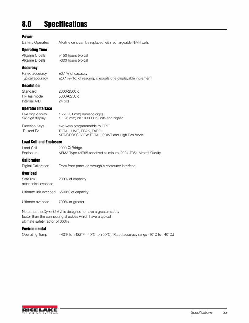
8.0 SpecificationsPower Battery Operated Alkaline cells can be replaced with rechargeable NiMH cells
Operating TimeAlkaline C cells >150 hours typical Alkaline D cells >300 hours typical
AccuracyRated accuracy ±0.1% of capacity Typical accuracy ±(0.1%+1d) of reading. d equals one displayable increment
ResolutionStandard 2000-2500 dHi-Res mode 5000-6250 dInternal A/D 24 bits
Operator InterfaceFive digit display 1.22'' (31 mm) numeric digitsSix digit display 1'' (26 mm) on 100000 lb units and higher
Function Keys two keys programmable to TEST F1 and F2 TOTAL, UNIT, PEAK, TARE,
NET/GROSS, VIEW TOTAL, PRINT and High Res mode
Load Cell and EnclosureLoad Cell 2000 Ω BridgeEnclosure NEMA Type 4/IP65 anodized aluminum, 2024-T351 Aircraft Quality
CalibrationDigital Calibration From front panel or through a computer interface
OverloadSafe link 200% of capacitymechanical overload
Ultimate link overload >500% of capacity
Ultimate overload 700% or greater
Note that the Dyna-Link 2 is designed to have a greater safetyfactor than the connecting shackles which have a typicalultimate safety factor of 600%
EnvironmentalOperating Temp - 40°F to +122°F (-40°C to +50°C), Rated accuracy range -10°C to +40°C.)
Specifications 33

34 MSI-7300 Dyna-Link 2 Technical Manual


September 09, 2016 PN 152160 Rev D
230 W. Coleman St. • Rice Lake, WI 54868 • USAU.S. 800-472-6703 • Canada/Mexico 800-321-6703 • International 715-234-9171 • Europe +31 (0)26 472 1319
Rice Lake Weighing Systems is an ISO 9001 registered company. © Rice Lake Weighing Systems Specifications subject to change without notice.
www.ricelake.com