technical manual - qntra · technical manual bl45-mt-fr ... troubleshooting ... technician shall...
TRANSCRIPT

Technical manual BL45-MT-FR The information contained in this document is the property of Automatic Systems and is confidential. The recipient is forbidden from using the information for purposes other than the use of the products or implementing a project in which they consult and communicate the information to a third party without the prior written agreement of Automatic Systems. The document may be modified without prior notice.
BL 45
TECHNICAL MANUAL (Translated from the French original notice)
Rev 0

p. 2/46
Technical manual BL45-MT-FR The information contained in this document is the property of Automatic Systems and is confidential. The recipient is forbidden from using the information for purposes other than the use of the products or implementing a project in which they consult and communicate the information to a third party without the prior written agreement of Automatic Systems. The document may be modified without prior notice.
Document revisions
Rev Date Written Checked Subject
00 2012-04-27 MFy First edition
p. 3/46
Technical manual BL45-MT-FR The information contained in this document is the property of Automatic Systems and is confidential. The recipient is forbidden from using the information for purposes other than the use of the products or implementing a project in which they consult and communicate the information to a third party without the prior written agreement of Automatic Systems. The document may be modified without prior notice.
TABLE OF CONTENTS
1. SAFETY WARNINGS ......................................................................................................... 4
2. INSTALLATION .................................................................................................................. 5
2.1. Storing the equipment before installation ........................................................................................ 5 2.2. Positioning the equipment – Installation drawing ........................................................................... 5 2.3. Assembly of the arm ........................................................................................................................... 7
2.3.1. Round aluminium arm .............................................................................................................. 8 2.3.2. Fibreglass rectangular arm (< 9 metres) .................................................................................. 9 2.3.3. Fibreglass rectangular arm (≥ 9 metres) ................................................................................ 10
2.4. Electrical connections ...................................................................................................................... 11
3. OPERATION ..................................................................................................................... 12
3.1. Location of the components ............................................................................................................ 12 3.2. Operating principle ............................................................................................................................ 13 3.3. Rotating base ..................................................................................................................................... 14
3.3.1. Assembly of barrier on rotating base ..................................................................................... 15 3.3.2. Installing the base/barrier assembly on-site .......................................................................... 15 3.3.3. Rotation of the housing .......................................................................................................... 15 3.3.4. Adjusting the rotation resistance of the housing .................................................................... 15 3.3.5. Position switch wiring (optional) ............................................................................................. 16
3.4. Locking of the arm (optional) ........................................................................................................... 17 3.5. Control boards ................................................................................................................................... 18
3.5.1. Circuit board 4E5133 ............................................................................................................. 19 3.5.2. Programmable logic controller 4E5331 .................................................................................. 20
4. MAINTENANCE ................................................................................................................ 24
4.1. Turning the power off ........................................................................................................................ 24 4.2. Manual raising of the arm ................................................................................................................. 24 4.3. Preventive maintenance ................................................................................................................... 25 4.4. Troubleshooting ................................................................................................................................ 26 4.5. Prolonged stop/destruction .............................................................................................................. 28 4.6. Adjusting the balancing springs ...................................................................................................... 29 4.7. Adjusting the deceleration sensors................................................................................................. 34 4.8. Adjusting the variable speed controller .......................................................................................... 36 4.9. Adjustment of loop sensors (optional) ........................................................................................... 37
5. TECHNICAL SPECIFICATIONS ....................................................................................... 38
6. DIMENSIONS .................................................................................................................... 39
7. WIRING DIAGRAMS ......................................................................................................... 40
8. CONFORMITY CERTIFICATE .......................................................................................... 45

p. 4/46
Technical manual BL45-MT-FR The information contained in this document is the property of Automatic Systems and is confidential. The recipient is forbidden from using the information for purposes other than the use of the products or implementing a project in which they consult and communicate the information to a third party without the prior written agreement of Automatic Systems. The document may be modified without prior notice.
1. SAFETY WARNINGS
Installing a barrier exposes the user to responsibilities with regards to the safety of people:
Circulation of pedestrians in the area where the barrier is moving must be banned (risk of being hit and pinching). Two pictograms for the prohibition of pedestrian access are provided with the equipment; the EC Machine Directive requires that they be affixed to either side of the barrier, in a location visible to pedestrians.
All operations performed on the equipment must be undertaken by qualified personnel. All operations that are not authorised or that are undertaken on this product by an unqualified technician shall automatically lead and ipso jure to the denial of the manufacturer’s warranty.
The access keys to the mechanism must only be used by personnel informed about the electrical and mechanical risks incurred by negligent handling. This person is required to lock the mechanism’s access door after completing the work.
As soon as the access door to the mechanism is opened, cut the power supply on the circuit breaker or the fuse housing (as appropriate).
Raise the arm before doing any work in the housing, in order to release the tension in the balancing springs and avoid untimely movement of the driving mechanism.
All internal elements that can be turned on or that move must be handled with care.
The equipment is configured at a “minimal risk” mode for its users. All modifications to the parameters must be undertaken by experienced and qualified personnel and in no way entails the responsibility of Automatic Systems.
The end of the arm must always be kept at a distance of at least 0.5 m from any object.
The barrier must be fully visible by the user before being actuated.
After a collision, even without apparent damages, the equipment must be carefully checked by an approved technician.
Install the arm and any accessories before any electrical tests (Ch. 2.3. ).
Never operate the barrier without bumpers (10, Ch. Erreur ! Source du renvoi introuvable.).
The installation of detection loops must be validated by qualified personnel who will determine their optimal configuration to adapt to vehicle type and passageway. WARNING: The risk of injury for people exists when using standard detection loops: they can incorrectly detect trucks and (motor) bikes and close the barrier on them!

p. 5/46
Technical manual BL45-MT-FR The information contained in this document is the property of Automatic Systems and is confidential. The recipient is forbidden from using the information for purposes other than the use of the products or implementing a project in which they consult and communicate the information to a third party without the prior written agreement of Automatic Systems. The document may be modified without prior notice.
2. INSTALLATION
Installation must be undertaken in compliance with the safety warnings (Ch. 1. ).
2.1. Storing the equipment before installation
Before installation, ensure that the equipment does not get damaged, leave it in its original packaging and place it in a dry area protected from dust, heat and weather. Store between -30 and +80°C.
2.2. Positioning the equipment – Installation drawing
Since the barrier cannot be laid flush with the road surface, a perfectly horizontal raised concrete base must be prepared, according to the installation drawing on the next page.
1. Assemble the fixing frame: Pass the four anchoring bolts (3) into the holes of the fixing frame (2) using a nut (7a) and a flat washer (6a) for each one. The threaded end of the anchoring bolts must be oriented upwards as illustrated in Fig. a. Secure the anchoring bolts on the fixing frame by putting a flat washer (6b) and a nut (7b) on each threaded rod with a 40 mm tail (Fig. b). Tighten the nuts. It is advisable to protect the threads sticking out of the fixing frame from concrete projections by means of adhesive tape.
2. Position a PVC tube (4) with a minimum diameter of 60 mm for the power supply and remote control wires to pass through (Fig. b). Where appropriate, position a PVC tube (5) with a diameter of 25 mm for the detection loop wires to pass through (optional). The cables should be at least 1 metre out of the concrete base.
3. Construct a concrete base (8) in which the fixing frame is to be centred. The fixing frame must be flush with the finished level of the concrete base and perfectly horizontal (Fig. b).
4. When the concrete is dry, remove the adhesive tape from the threads, remove the nuts (7b) and the flat washers (6b), put the barrier housing onto the concrete base and keep it in place by means of the washers (6b) and the nuts (7b) (Fig. c). The concrete base is designed to be smaller than the barrier housing in order to prevent water standing at the bottom of the housing (Fig. d).
3
7a
6a
6b
7b 2
40 mm
4 5
8
Fig. a
Fig. b
Fig. c
Fig. d

p. 6/46
Technical manual BL45-MT-FR The information contained in this document is the property of Automatic Systems and is confidential. The recipient is forbidden from using the information for purposes other than the use of the products or implementing a project in which they consult and communicate the information to a third party without the prior written agreement of Automatic Systems. The document may be modified without prior notice.
p. 7/46
Technical manual BL45-MT-FR The information contained in this document is the property of Automatic Systems and is confidential. The recipient is forbidden from using the information for purposes other than the use of the products or implementing a project in which they consult and communicate the information to a third party without the prior written agreement of Automatic Systems. The document may be modified without prior notice.
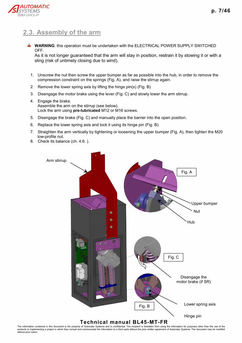
2.3. Assembly of the arm
WARNING: this operation must be undertaken with the ELECTRICAL POWER SUPPLY SWITCHED OFF.
As it is not longer guaranteed that the arm will stay in position, restrain it by stowing it or with a sling (risk of untimely closing due to wind).
1. Unscrew the nut then screw the upper bumper as far as possible into the hub, in order to remove the compression constraint on the springs (Fig. A), and raise the stirrup again.
2. Remove the lower spring axis by lifting the hinge pin(s) (Fig. B)
3. Disengage the motor brake using the lever (Fig. C) and slowly lower the arm stirrup.
4. Engage the brake. Assemble the arm on the stirrup (see below). Lock the arm using pre-lubricated M12 or M16 screws.
5. Disengage the brake (Fig. C) and manually place the barrier into the open position.
6. Replace the lower spring axis and lock it using its hinge pin (Fig. B).
7. Straighten the arm vertically by tightening or loosening the upper bumper (Fig. A), then tighten the M20 low-profile nut.
8. Check its balance (ch. 4.6. ).
Arm stirrup
Fig. A
Upper bumper
Hub
Fig. C
Fig. B
Disengage the motor brake (if SR)
Hinge pin
Nut
Lower spring axis

p. 8/46
Technical manual BL45-MT-FR The information contained in this document is the property of Automatic Systems and is confidential. The recipient is forbidden from using the information for purposes other than the use of the products or implementing a project in which they consult and communicate the information to a third party without the prior written agreement of Automatic Systems. The document may be modified without prior notice.
2.3.1. Round aluminium arm
No. Qty Name Ref.
1 1 Round aluminium arm, Ø100
2 1 Round aluminium arm, Ø89.5
3 1 Round aluminium arm, Ø83.5
4 1 Central stirrup for round arm (in 2 parts) LIS0037
5 2 Fixing bracket for central arm LIS0038
6 4 Assembly fixing bracket for round arm LIS0039
7 6 H M12 x 40 screw (stainless steel, class 80)
8 8 CBLH M8 x 25 screw (stainless steel, class 80)
9 6 M 12 flat washer (stainless steel, class 80)
10 2 Tensioner bracing plate (according to length and/or options) LIS0092
11 1 Bracing collar, Ø83.5(according to length and/or options) LIS0089
12 1 Tensioner cable (according to length and/or options) LIS0256 LIS0534 LIS0816
6 H M16 x 40 screw with series M washer, stainless steel (for stirrup without tensioner)
13 4 H M16 x 50 screw for tensioner (according to length and/or options) 2 H M16 x 40 screw, stainless steel
Note:
Lubricate the M8, M12 and M16 stainless-steel screws before assembly
Adhere to a tightening torque of 73 Nm when tightening H M12 x 40 screws (no. 7)
Adhere to a tightening torque of 21 Nm when tightening CBLH M8 x 25 screws (no. 8) Adhere to a tightening torque of 180 Nm when tightening H M16 x 40 screws (no. 13)
7
1
8
6
2
8
3 6
11
12
4
5 9
10
13

p. 9/46
Technical manual BL45-MT-FR The information contained in this document is the property of Automatic Systems and is confidential. The recipient is forbidden from using the information for purposes other than the use of the products or implementing a project in which they consult and communicate the information to a third party without the prior written agreement of Automatic Systems. The document may be modified without prior notice.
2.3.2. Fibreglass rectangular arm (< 9 metres)
No. Qty Name Ref.
1 1 Fibreglass arm support extension LIS0939
2 2 Central stirrup LIS0578
3 6 H M16 x 40 screw (stainless steel, class 80)
4 6 Washer Ø16 series M (stainless steel, class 80)
5 6 H M10 x 150 screw (stainless steel, class 80)
6 12 Washer Ø16 series M (stainless steel, class 80)
7 6 NYLSTOP M10 nut (stainless steel, class 80)
Note:
Lubricate the M16 stainless-steel screws before assembly
Adhere to a tightening torque of 180 Nm when tightening H M16 x 40 screws (no. 3)
Adhere to a tightening torque of 42 Nm when tightening H M12 x 40 screws (no. 5)
6
1
4
7
3
2
4 3 5 6 2

p. 10/46
Technical manual BL45-MT-FR The information contained in this document is the property of Automatic Systems and is confidential. The recipient is forbidden from using the information for purposes other than the use of the products or implementing a project in which they consult and communicate the information to a third party without the prior written agreement of Automatic Systems. The document may be modified without prior notice.
2.3.3. Fibreglass rectangular arm (≥ 9 metres)
Number Qty Name BCA Ref.
1 1 Fibreglass arm support extension LIS0939
2 1 Central stirrup body LIS0718-2
3 1 Central stirrup flange LIS0718-1
4 6 H M16 x 40 screw (stainless steel, class 80)
5 6 Washer Ø16 series M (stainless steel, class 80)
6 6 H M10 x 150 screw (stainless steel, class 80)
7 12 Washer Ø10 series M (stainless steel, class 80)
8 6 NYLSTOP M10 nut (stainless steel, class 80)
9 4 CHC M12 x 70 screw (stainless steel, class 80)
10 8 Washer Ø12 series M (stainless steel, class 80)
11 4 NYLSTOP M12 nut (stainless steel, class 80)
Note:
Lubricate the M16 stainless-steel screws before assembly
Adhere to a tightening torque of 180 Nm when tightening H M16 x 40 screws (no. 4)
Adhere to a tightening torque of 42 Nm when tightening H M10 x 40 screws (no. 6)
Adhere to a tightening torque of 73 Nm when tightening CHC M12 x 70 screws (no. 9)
7
8
10
9
1
4
3
2 5 6 7
11
4 5
10

p. 11/46
Technical manual BL45-MT-FR The information contained in this document is the property of Automatic Systems and is confidential. The recipient is forbidden from using the information for purposes other than the use of the products or implementing a project in which they consult and communicate the information to a third party without the prior written agreement of Automatic Systems. The document may be modified without prior notice.
2.4. Electrical connections
The operations must be undertaken in accordance with the safety warnings, Ch. 1.
Connections must be executed in accordance with the wiring diagrams provided inside the equipment, which remain the reference.
In order to avoid interference, power and control cables must pass through two different conduits separated by at least 10 cm.
WARNING: The arm must be mounted before proceeding to electrical connections!
Open the fuse holder or put the switch, located on the barrier terminal block, to OFF (as appropriate)
Connect the single-phase 220 volt electrical power supply to the “N” and “PH” connectors.
It is absolutely essential that the ground wire is connected.
Upstream of the power supply provide: - Either a 10 A/300 mA leakage breaker (max. 5 barriers). - Or a 10 A/30 mA leakage breaker of the selective Super Immunised type (max. 1
barrier).
Connect the various control units and possible options in compliance with the diagram supplied, avoiding the power cable.
Connect the ground wires to their terminals: - Cable between the housing and the cover
(check this connection each time the cover is closed) - Cable between the housing and the doors
(check this connection each time the door is closed) - Cable between the terminal block and the control board.
Test that the equipment is operating correctly.

p. 12/46
Technical manual BL45-MT-FR The information contained in this document is the property of Automatic Systems and is confidential. The recipient is forbidden from using the information for purposes other than the use of the products or implementing a project in which they consult and communicate the information to a third party without the prior written agreement of Automatic Systems. The document may be modified without prior notice.
3. OPERATION
3.1. Location of the components
No. Name Ref.
1 Cover, locked with two locks and keys CHA0032
2 Housing CHA0010
3 Front door, locked by lock and key CHA0013
4 Bearing for main shaft (x2 per barrier) ACM0044
5 Detection cam (x2 per barrier) DET0025
6 Bracket for inductive sensors DET0024
7 Inductive position sensor (x2 per barrier)
8 Protective cover CHA0026
9 Gear motor A102 SR 4E4580
10 Bumper (x2 per barrier)
11 Sector gear
12 “x” spring assembly (x1 or x2 per barrier) (see Ch. 4.6. ). LRESD"x"
13 Hub ARB0016
14 Plummer block ACM0043
15 Pinion ARB0019
16 Control board
17 Variable speed controller
18 Arm
19 Lever for disengaging brake
20 Circuit breaker
21 Reinforcing V-block, optional arm locking support
18
19
17
16
20
21

p. 13/46
Technical manual BL45-MT-FR The information contained in this document is the property of Automatic Systems and is confidential. The recipient is forbidden from using the information for purposes other than the use of the products or implementing a project in which they consult and communicate the information to a third party without the prior written agreement of Automatic Systems. The document may be modified without prior notice.
3.2. Operating principle
The numbers in this chapter refer to the illustrations in Ch. 3.1. .
The opening of the arm (18) is controlled by the user (via a lockable switch, a push-button and a radio transmitter), by the presence detector loops buried under the road, or by an outside unit. Closing is controlled in the same way, or automatically after a time delay.
The motion generated by the gear motor (9) is transmitted to the arm by means of pinion and sector gears (15 + 11).
The speed of the arm movement is controlled by the variable speed controller (17). The movement parameters are adjusted in the factory in order to offer brisk acceleration and gentle deceleration at the end of the movement. The 2 inductive deceleration sensors (7) indicate the extreme arm positions (open and closed) to the control board (16). The latter coordinates the activity of the barrier: movement management, options, processing of incoming and outgoing information, etc. This information can, however, be transferred and processed by an external terminal (not supplied by Automatic Systems).
There are one to six preloaded balancing springs (12) to act like counterweights, in order to help the motor open and close the barrier. An electromagnetic brake holds the arm in its two extreme positions (open and closed) and during a Stop command.
In order to increase protection against vandalism (forcing the arm), the latter can furthermore be fitted with an optional mechanical locking system, which locks the arm in the open and/or closed position (see Ch. Erreur ! Source du renvoi introuvable.).
The rotating base (Ch. 3.3) allows the barrier to be positioned parallel to the roads in order that maintenance and regular tests can be undertaken without restricting traffic.

p. 14/46
Technical manual BL45-MT-FR The information contained in this document is the property of Automatic Systems and is confidential. The recipient is forbidden from using the information for purposes other than the use of the products or implementing a project in which they consult and communicate the information to a third party without the prior written agreement of Automatic Systems. The document may be modified without prior notice.
3.3. Rotating base
The rotating base allows the barrier to be positioned parallel to the roads in order that maintenance and regular tests can be undertaken without restricting traffic.
The two maintenance positions can be achieved by rotating the barrier 90° in either direction.
The indexing device allows the maintenance operator to lock the rotation of the barrier at the desired position.
This device also allows the physical consequences of bumps to be limited by allowing the barrier to rotate via the breaking of an adapted part.
Two adjustable resistances allow the effort needed to rotate the barrier housing to be adjusted. Two sensors indicate the position of the housing: the first when the barrier is perpendicular to the road, the second when it is parallel (maintenance position).
Bottom of joint
aligned with flange
V ring
Fastening screws and washers
Rectangular caps
Indexation and breaking device
Barrier base plate
Pin Ø8 and slot
V ring joint
Outside ring
V markers
Normal/rotated position sensor (no. 1)
Inside ring
Maintenance position switch (no. 2)
Position switch cables
Unlocking Locking Ref. EMB0994

p. 15/46
Technical manual BL45-MT-FR The information contained in this document is the property of Automatic Systems and is confidential. The recipient is forbidden from using the information for purposes other than the use of the products or implementing a project in which they consult and communicate the information to a third party without the prior written agreement of Automatic Systems. The document may be modified without prior notice.
3.3.1. Assembly of barrier on rotating base
When placing the barrier on the rotating base, take care to not damage the position switch cables. In order to do this, coil and place the extra length of the cables in the inside ring.
Place the barrier on the rotating base, respecting the position of the inside ring (pin Ø8 aligned with the slot of the outside ring) and aligning the V markers with the barrier holders.
Attach the barrier using 4 screws and washers.
Position the 4 rectangular caps.
Replace the V ring joint (edge in contact with the barrier base plate).
After positioning the barrier, ensure that it can rotate 90° in each direction.
Tighten the indexation and breaking device all the way.
3.3.2. Installing the base/barrier assembly on-site
In order to allow the barrier to rotate 90° in each direction when the base/barrier assembly is to be installed on-site, it is essential that when installing the assembly on-site that the rotating base is locked in the normal operating position (pin removed) and that the V markets are aligned with the barrier holders.
3.3.3. Rotation of the housing
To put the barrier housing in the maintenance position, unlock the indexation pin.
Rotate the barrier 90° in one direction and lock the indexation pin in order to lock the rotation.
To return the barrier housing to the normal operating position, carry out the inverse of the above operations.
To lock or unlock the indexation pin, pull and turn the split ring.
3.3.4. Adjusting the rotation resistance of the housing
In order to adjust the effort needed to rotate the barrier housing, use a male 6 mm Allen key on the two screws visible in the inside ring.
Tightening these screws increases the rotation resistance, loosening them decreases the rotation resistance.
Adjusting the resistance

p. 16/46
Technical manual BL45-MT-FR The information contained in this document is the property of Automatic Systems and is confidential. The recipient is forbidden from using the information for purposes other than the use of the products or implementing a project in which they consult and communicate the information to a third party without the prior written agreement of Automatic Systems. The document may be modified without prior notice.
3.3.5. Position switch wiring (optional)
Two position switches indicate the position of the housing in relation to the road.
Switch no. 1 changes state when the barrier leaves its normal operating position (rotated state).
Switch no. 2 changes state when the barrier achieves the maintenance position.
The wiring of these switches is as follows:
Bla
ck
Bla
ck
Wh
ite
Red
Wh
ite
Red
Switch 1
“Normal/Rotated”
Switch 2
“Maintenance”
NC NO
COM
NC NO
COM

p. 17/46
Technical manual BL45-MT-FR The information contained in this document is the property of Automatic Systems and is confidential. The recipient is forbidden from using the information for purposes other than the use of the products or implementing a project in which they consult and communicate the information to a third party without the prior written agreement of Automatic Systems. The document may be modified without prior notice.
3.4. Locking of the arm (optional)
When the arm is in the lowered position, the lock is powered, the spring (1) is compressed, the jaws (2 and 3) are closed around the locking pin (4), the locking pin is fastened to the hub, which in turn is attached to the arm’s driving shaft, which is therefore locked.
During an Open command or when the electrical power supply for the barrier is cut, the electromagnet (5) is turned off. Thus, the return spring (1) causes the movement of the connecting bar (6) towards the electromagnet, causing the jaws (2 and 3) to open. With the locking pin (4) free, the arm is unlocked.
During a command, if the jaws become jammed by the locking pin, (for example following an act of vandalism), the inductive sensor will not detect that they are open and thus the arm is unlocked.
In this situation, a brief movement in the opposite direction will be given in order to unjam the mechanism, allowing the barrier to resume the ongoing command.
2 3
4
5
6
1
Lock receiving power in the closed position
Lock not receiving power in the open position

p. 18/46
Technical manual BL45-MT-FR The information contained in this document is the property of Automatic Systems and is confidential. The recipient is forbidden from using the information for purposes other than the use of the products or implementing a project in which they consult and communicate the information to a third party without the prior written agreement of Automatic Systems. The document may be modified without prior notice.
3.5. Control boards
The barrier is equipped with one of the following boards:
No. Name Ref.
70 Metal plate 4E5468
71 Circuit board 4E5331
72 Circuit board 4E5133
73 Variable speed controller (+ filter) VAR0747
74 Terminal block bracket 4E5848
75 DIN rail 4E5331
76 Terminal block -
77 Power supply (optional)
78 Radio receiver (optional)

p. 19/46
Technical manual BL45-MT-FR The information contained in this document is the property of Automatic Systems and is confidential. The recipient is forbidden from using the information for purposes other than the use of the products or implementing a project in which they consult and communicate the information to a third party without the prior written agreement of Automatic Systems. The document may be modified without prior notice.
3.5.1. Circuit board 4E5133
Adjusting time delays:
T1: (30 seconds by default)
Closing time delay if no vehicle passes through.
Can be adjusted from 0 to 60 seconds by turning the left potentiometer anticlockwise to increase the value.
T2: (2 seconds by default)
Closing time delay after vehicle passes through.
Can be adjusted from 0 to 20 seconds by turning the middle potentiometer anticlockwise to increase the value.
T3: (2 seconds by default)
Time delay before changing to slow speed at end of opening and closing movement.
Can be adjusted from 0 to 6 seconds by turning the right potentiometer anticlockwise to increase the value.
T1 T2 T3

p. 20/46
Technical manual BL45-MT-FR The information contained in this document is the property of Automatic Systems and is confidential. The recipient is forbidden from using the information for purposes other than the use of the products or implementing a project in which they consult and communicate the information to a third party without the prior written agreement of Automatic Systems. The document may be modified without prior notice.
3.5.2. Programmable logic controller 4E5331
1. Display operation
When idle, the display lighting is turned off. Press one of the 3 push buttons to turn it on. The display turns off if it is not used for more than 5 minutes. The potentiometer located on the left of the display allows the contrast to be adjusted.
In its initial state, the display indicates the operation mode (AUTOMATIQUE), the saved program number (AUTO: PG07) and the following 3 options:
MANU
This mode gives the option of opening and closing the barrier “locally” from the circuit board. The AUTOMATIQUE function is blocked. When closing, the safety features are ACTIVE and the push button must remain pressed.
Press twice on AUTO to return to the initial state.
VISU
This mode allows the option of displaying all the program parameters. When displaying the parameters, the barrier operates normally. At the end of the drop-down menu, the time delays, inputs, outputs and internal bits are displayed dynamically.
PROG
Gives the option of programming the pre-saved modifiable parameters. During programming, the barrier no longer operates.
2. Glossary of display terms
AUTO Return to automatic operating mode
PROG Move into the programming mode
VISU Move into the parameter display mode
MANU Move to manual mode where the barrier operates via push buttons
OUV Open barrier in MANU mode
FERM Close barrier in MANU mode
SUITE Move from one step to another in drop-down menus
> Move cursor
+ Increase value selected with cursor
- Decrease value selected with cursor
OK Confirm a choice or modification
ANNUL Exit without saving
SAUV Save a modification Note: all modifications must be saved individually.
QUIT Exit current display
E : XXX Error mode
V : XXX Display mode
P : XXX Programming mode

p. 21/46
Technical manual BL45-MT-FR The information contained in this document is the property of Automatic Systems and is confidential. The recipient is forbidden from using the information for purposes other than the use of the products or implementing a project in which they consult and communicate the information to a third party without the prior written agreement of Automatic Systems. The document may be modified without prior notice.
3. Display error codes
E : Defaut mode Unknown operating mode
E : Prog Invalide The requested program does not exist
E : Lecture eeprom Error reading from EEPROM
E : Ecriture eeprom Error writing on EEPROM
E : Eeprom vide EEPROM is empty
4. Time delays (can be adjusted from 0 to 999 seconds)
T01 - Closing time delay after vehicle passes under security barrier (2 s by default).
T02 - Closing time delay if no vehicle passes through (30 s by default).
T03 - Time delay before changing to slow speed at end of opening and closing movement (2 s by default).
T04 - Opening delay.
T05 - Closing delay.
T06 - Time delay after movement.
T07 - Light turned on for 0.5 s (T07 + T08 = adjust frequency of flashing light).
T08 - Light turned off for 0.5 s (T07 + T08 = adjust frequency of flashing light).
T09 - Maintaining order of automatic opening loop (for barrier loopback).
T10 - Delay in releasing opening (internal locking).
T11 - Delay in releasing closing (internal locking).
T12 - Time delay before fault detection at S9 output (longer than moving time).
Note: all modifications must be saved individually.
5. Predefined functions (FP - Fonctions Prédéfinies)
FP1 - 0 Manual closing in E7, step-by-step (without automatic continuation). 1 Manual closing in E7 with automatic continuation.
FP2 - Not used.
FP3 - Not used.
FP4 - 0 If vehicle is detected when closing, the arm opens. 1 If vehicle is detected when closing, the arm remains in its current position.
FP5 - Not used.
FP6 - Not used.
FP7 - Not used.
FP8 - Not used.
FP9 - Not used.
FP10 - Not used.
FP11 - 0 R2 light on the arm flashes when moving. 1 R2 light on the arm flashes when moving and when lowered.
FP12 - 0 R2 light on the arm flashes when moving. 1 R2 light on the arm flashes when moving and when raised.

p. 22/46
Technical manual BL45-MT-FR The information contained in this document is the property of Automatic Systems and is confidential. The recipient is forbidden from using the information for purposes other than the use of the products or implementing a project in which they consult and communicate the information to a third party without the prior written agreement of Automatic Systems. The document may be modified without prior notice.
FP13 - Not used.
FP14 - 0 No internal locking of the barrier. 1 Activate Standard internal locking (electric locking when raised and lowered and unlocked when power is cut).
FP15 - 0 Operation of internal locking if FP14 set to 1. 1 Electric locking when raised and lowered and unlocked when power is cut.
FP16 - 0 Operation of internal locking if FP14 set to 1. 1 Electric locking when raised and lowered, and unlocked when lowered and raised when
power is cut.
6. Magnetic loops
- [B PRES] Safety: This variable is used to detect a vehicle under the arm.
- [B V1] Validation1: not used in this program.
- [B V2] Validation2: not used in this program.
- [B OUV] Open-request: Allows automatic opening via a loop (for an exit, for example.)
Connect the loops to terminal block XB1
Each of the 4 magnetic loops can be programmed independently.
As standard, loop B1 is the safety and loop B3 orders automatic opening.
Loops B2 and B4 can be configured and used provided that dual detectors are used.
7. Safeties
The safeties of the barrier may be effected using magnetic loops, using retroreflective or emitter/receptor sensors, using ultrasound or other safety devices with dry contacts.
Connection of the safety contacts to terminal block XG4 +24v/E8 for signal in NC and +24v/E11 for signal in NO.
If the safeties are present during closing:
- the barrier opens again if FP4 is set to 0.
- the barrier remains in its position if FP4 is set to 1.
8. Connection of main inputs (see electrical diagrams)
All signals connected to the inputs must be volt-free dry contacts (except magnetic loops).
If necessary, for certain accessories (radio, reader, etc.), power supplies are available from terminal block XG1 (+24V d.c. and +12V d.c.) or from terminal block XD1 (24V a.c.). These power supplies are limited to a maximum of 1 ampere.
Manual control box
Stop button or emergency stop (connection to XG3 +24v/E4 and remove the existing shunt). A constant action on this input causes the barrier to stop immediately.
Distance/Local contact (connection to XG3 +24v/E5) Input inactive for distance operation and active for local operation with the open push button 24v/E6 and the close push button 24v/E7 or the 3-way switch.
Open button (connection to XG3 +24v/E6) This input is automatically maintained and operational only in Local mode.

p. 23/46
Technical manual BL45-MT-FR The information contained in this document is the property of Automatic Systems and is confidential. The recipient is forbidden from using the information for purposes other than the use of the products or implementing a project in which they consult and communicate the information to a third party without the prior written agreement of Automatic Systems. The document may be modified without prior notice.
Close button (connection to XG3 +24v/E7) Step by step closing. Operational only in Local mode. If FP1 is set to 1, the signal in E7 is automatically maintained.
Client open (connection to XG5 +24v/E14) The barrier is opened when the input is activated. The command operates only in Distance mode.
Client close (connection to XG5 +24v/E15) The command operates only in Distance mode.
9. Connection of main outputs (see electrical diagrams)
Barrier fault (connection to XD6 at +S/S9/-S) This output is active when there is no fault with the barrier. Summary of faults: lack of power, fault in sheet, fault in controller and arm blocked at 45°.
Audible alarm (connection to XD4 at S2 C2/NO2 + 24V d.c. power supply). Sounds while arm is closing.
Flashing lights (connection to XD4 at S1 C1/NO1 + suitable power supply). Option of connecting incandescent, LED or xenon lights. In standard mode, these operate when the barrier is moving (rising and falling). If FP11 is set to 1, the light also operates when arm is lowered. If FP12 is set to 1, the light also operates when arm is raised. The flashing frequency can be modified by changing the value of the T7 and T8 time delays. The T4 time delay can make the flashing start before opening. The T5 time delay can make the flashing start before closing. The T6 time delay can make the flashing stop after moving.
Presence signal on safety loop (connection to XD5 C3/NO3) Signal on S3 the whole time the vehicle is detected by the safety.
Moving to Local mode signal (connection to XD5 C4/NO4) Signal on S4 the whole time that local signal is activated or when moving to MANU mode on the card.
Barrier open signal (connection to XD5 C5/NO5)
Barrier closed signal (connection to XD5 C6/NO6)

p. 24/46
Technical manual BL45-MT-FR The information contained in this document is the property of Automatic Systems and is confidential. The recipient is forbidden from using the information for purposes other than the use of the products or implementing a project in which they consult and communicate the information to a third party without the prior written agreement of Automatic Systems. The document may be modified without prior notice.
4. MAINTENANCE
4.1. Turning the power off
Trip the circuit breaker (20, Ch.3.1. ).
4.2. Manual raising of the arm
1. Cut electrical power supply.
2. Operate the brake unlocking lever (19, Ch.3.1. ) and raise the arm manually.
3. Release the brake unlocking lever.

p. 25/46
Technical manual BL45-MT-FR The information contained in this document is the property of Automatic Systems and is confidential. The recipient is forbidden from using the information for purposes other than the use of the products or implementing a project in which they consult and communicate the information to a third party without the prior written agreement of Automatic Systems. The document may be modified without prior notice.
4.3. Preventive maintenance The numbers in this chapter refer to the illustrations in Ch. Erreur ! Source du renvoi introuvable.
WARNING: Never operate the barrier without bumpers (10, Ch. Erreur ! Source du renvoi introuvable.), even manually! Maintenance activities must be carried out in compliance with the safety warnings listed in Chapter 1. Unlock and remove the side and front doors (3) without damaging the ground wire that connects them to the housing. Cut the circuit breaker (20). Remove the cover (1) without damaging the ground wire that links it to the housing.
After the first 1,000 operations
∙ verify that the deceleration sensors are adjusted properly (Ch. 4.7. ).
Every 6 months
∙ Visual check of the position of the arm: verify whether the arm is properly vertical and horizontal
and that it does not bounce. If not, check whether the deceleration sensors (7) are properly adjusted (Ch.4.7. ) and whether the rubber bumpers (10) are damaged.
∙ Clean the outside of the housing and the arm using a soft rag soaked with a mild detergent. For countries with a lot of sun, we recommend treating the outside of the housing with polish.
∙ Perform an audio check of the rotation of the bearings. ∙ Test that the brake disengages: operate the lever (19) and lift the arm manually. ∙ Verify that the rotating base is operating correctly both mechanically and electronically (test
sensors).
Every year ∙ Check that the fastenings are tightened properly (torque): bearings, gear motor, hub, sensors,
spring assembl(y/ies), fastening of the arm, fastening to the ground, etc. ∙ Inspection of the condition of the electrical connections. ∙ Lubrication, using an anti-corrosive multi-purpose grease:
∙ gears (11 + 15), ∙ upper bearing(s) of the spring assembly (42), ∙ spring guide rods (25 + 33), ∙ lower part (in contact with the plate) of the clips (83) of the arm’s locking system (Ch.
Erreur ! Source du renvoi introuvable.). Note: The bearings (4) and gear motor (9) are lubricated for their entire service life. Simply check their tightness (absence of leaks).
∙ Remove dust from the control board + variable speed controller such that any particulate build-ups are removed.
∙ Check that the inside of the barrier is clean.

p. 26/46
Technical manual BL45-MT-FR The information contained in this document is the property of Automatic Systems and is confidential. The recipient is forbidden from using the information for purposes other than the use of the products or implementing a project in which they consult and communicate the information to a third party without the prior written agreement of Automatic Systems. The document may be modified without prior notice.
4.4. Troubleshooting
SYMPTOM POSSIBLE CAUSES APPROPRIATE SOLUTIONS
The barrier stays open
Open command is given continually
Check that the open command is a pulse and not a constant command.
The FORCED OPENING input has been activated
Verify whether a locking order has been given at the control panel, barrier switch or manual control box (optional).
The loop sensor (optional) remains engaged
Review the sensor’s sensitivity adjustment and reset the loop sensor. Adjusting the sensitivity adjustment to a setting that is too high may cause locking in the open position.
Check the condition of the LEDs on the detector, which indicate whether it and/or the loop are in good condition.
Ultrasound detection engaged
Check the adjustment settings (different frequency for each ultrasound device/contact type)
The barrier stays locked
The variable speed controller is defective
See the list of defects regarding the variable speed controller (Ch.4.8. ).
Control board 4E5331 is faulty (LOK LED turned off)
Verify whether the 5 V and 24 V LEDs are lit and whether the fuse is out of order. If the fuse is operational, cut the power supply, disconnect all terminal blocks on the card (except power supply), reconnect the power and connect the terminal blocks one by one to determine which terminal block is short-circuiting.
Verify the error codes on the display. If the display is turned off, verify the contrast adjustment settings using the potentiometer to the left of the display.
Defaut mode: Unknown operating mode Prog Invalid: The requested program does
not exist Lecture eeprom: Error reading from EEPROM Ecriture eeprom: Error writing on EEPROM Eeprom vide: EEPROM is empty
Control board 4E5133 is faulty (OK LED turned off)
Verify whether the fuse is out of order. If the fuse is operational, cut the power supply, disconnect all terminal blocks on the card (except power supply), reconnect the power supply and connect the terminal blocks one by one to determine which terminal block is short-circuiting.
The deceleration sensor provides incorrect information
In the lowered position: ensure that only the corresponding inductive sensor is in the cut-out of the lowered position cam.
In the raised position: ensure that only the corresponding inductive sensor is in the hollow of the raised position cam.

p. 27/46
Technical manual BL45-MT-FR The information contained in this document is the property of Automatic Systems and is confidential. The recipient is forbidden from using the information for purposes other than the use of the products or implementing a project in which they consult and communicate the information to a third party without the prior written agreement of Automatic Systems. The document may be modified without prior notice.
SYMPTOM POSSIBLE CAUSES APPROPRIATE SOLUTIONS
The barrier closes a long time after the vehicle has passed
The closing time delay after a vehicle has passed through is too long
See procedure for adjusting time delays (Ch.Erreur ! Source du renvoi introuvable.).
The open order is still given when a vehicle is passing through
Adjust the open order for the barrier to a pulse time below 1 second.
The barrier opens by itself
The opening loop (optional) is too sensitive
Adjust the sensitivity and/or frequency of the opening sensor. Adjusting the sensitivity adjustment to a setting that is too high or to an incorrect frequency can lead to untimely openings.
The access control system gives untimely orders
Inspect it. Replace it with a push button to carry out tests.
The barrier opens and closes immediately afterwards
The open pulse is given on the FORCED OPEN or AUTOMATIC OPEN input
Connect the open order to the READER input.
The barrier is not stable and during opening the signal from the cell is no longer aligned
Properly secure the barrier to the ground.
The barrier bounces in the raised and lowered position
Too much stress on the rubber bumpers inside the barrier
Adjust the cams in order to anticipate the change to slow speed and/or adjust the end of movement time delay.
The motor makes noise but the barrier does not move
The brake’s supply circuit
is out of service
Open the motor’s terminal board and check whether the diode bridge step-down transformer is in good condition. Input voltage: 240 V a.c. – Output voltage: 110 V rectified.
At the input of the diode bridge, measure whether it is powered during movement.
Check if the brake (NC contact) is connected to the variable speed controller.
The mains power turns off when the barrier voltage is switched on
The leakage breaker is not adapted
Use a 300 mA leakage breaker for up to three barriers and for cases requiring a 30 mA system, use a SI type circuit breaker (super-immunised) for each barrier.

p. 28/46
Technical manual BL45-MT-FR The information contained in this document is the property of Automatic Systems and is confidential. The recipient is forbidden from using the information for purposes other than the use of the products or implementing a project in which they consult and communicate the information to a third party without the prior written agreement of Automatic Systems. The document may be modified without prior notice.
4.5. Prolonged stop/destruction
If the equipment is not going to be used for a long period of time:
Store it under the same conditions as before installation (Ch.2.1. ).
Leave it connected to the mains supply. With motor constantly receiving power, a certain temperature in the housing is sustained. This reduces condensation issues and prevents the oil of the speed-reduction gear from freezing - that would prevent the same level of performance being achieved during the first operations executed after a long idle period. Note: If the equipment has been stored without power supplied and the ambient temperature is below -15°C (5°F), it is important to warm it before turning it on. The heating system must be activated for between 30 minutes and 1 hour before the equipment is turned on.
Before the start-up, carry out a new running-in period of 3,000 opening and closing operations.
When the equipment is withdrawn from service, scrap the various components through the appropriate channels (metal parts, electronic components, etc.) according to the legislation in force.

p. 29/46
Technical manual BL45-MT-FR The information contained in this document is the property of Automatic Systems and is confidential. The recipient is forbidden from using the information for purposes other than the use of the products or implementing a project in which they consult and communicate the information to a third party without the prior written agreement of Automatic Systems. The document may be modified without prior notice.
4.6. Adjusting the balancing springs
No. Name Ref.
25 Central rod RES0005
26 Guide socket RES0007
27 Nylstop M16 nut (steel)
28 M16 flat washer (steel)
29 Upper flange plate RES0001
30 Compression spring RES0003
31 Guide tube RES0053
32 Lower flange plate RES0002
33 Double rod RES0006
34 Nylstop M16 nut (steel)
40-A H M20 x 140 NF EN 24014 screw (steel, class 8.8) (376 Nm)
40-B H M20 x 180 NF EN 24014 screw (steel, class 8.8) (376 Nm)
41 Bumper bearing ACM0047
42 3304B double-row bearing ACM0048
43 Steel spacer ACM0045
44 H M16 x 100 screw (steel, class 8.8) (193 Nm)
45 Nylon washer ACM0046
46 M16 flat washer (steel)
47 Eccentric for adjusting balance (x2 per barrier) RES0200
48 M20 flat washer (steel)
49 H M20 x 80 NF EN 24014 screw (steel, class 8.8) (376 Nm)
50 Nylstop M20 nut (steel)
51 Rubber bumper (x2 per barrier) ACM0028
52 M20 bumper (x2 per barrier if no internal locking option) ACM0030
53 Nylstop M16 nut (steel)
54 Hm M20 nut (steel) (x2 per barrier)
55 Hub ARB0016
56 Sector gear ARB0015
57 Hinge pin Ø4.5
58 Spring pin axis RES0009
RA
TIN
G “
A”
Close-up A

p. 30/46
Technical manual BL45-MT-FR The information contained in this document is the property of Automatic Systems and is confidential. The recipient is forbidden from using the information for purposes other than the use of the products or implementing a project in which they consult and communicate the information to a third party without the prior written agreement of Automatic Systems. The document may be modified without prior notice.
AS
SEM
BLY
OF A
SP
RIN
G A
SS
EM
BLY
(1
to
3 s
prin
gs)
AS
SEM
BLY
FO
R T
WO
SP
RIN
G A
SS
EM
BLIES
(4
to 6
sp
rin
gs)

p. 31/46
Technical manual BL45-MT-FR The information contained in this document is the property of Automatic Systems and is confidential. The recipient is forbidden from using the information for purposes other than the use of the products or implementing a project in which they consult and communicate the information to a third party without the prior written agreement of Automatic Systems. The document may be modified without prior notice.
Note: the barrier was adjusted and tested in the factory according to the instructions listed on the order form. Any modification, such as the addition of equipment (panels, lights, etc.), or the modification of the useful length of the arm may require the readjustments of the balance compensation for the moving assembly.
The tension in the spring must be adjusted so as to ensure minimum stress on the motor when opening and closing the barrier:
Release the brake by activating the lever (19), slightly lift the arm then release it: it must stay balanced. Repeat the operation for the arm’s various angular positions.
If the arm falls down, the spring compression must be increased.
If the arm rises, the spring compression must be decreased.
Adjusting the spring compression:
1. Tighten and loosen the nuts (27) to increase and decrease respectively the spring compression (use a deep size 24 socket). WARNING: plates (29) and (32) must remain parallel and the distance between them (rating A)
may not be smaller than 445 mm when the springs are compressed, with the barrier lowered (arm in the lowered position), in order for the springs not to deteriorate. Also keep a space of 5 mm between plate 32 and rod 33 when the arm is in the vertical position and the spring is released (see close-up “A”). Adjust using nut 34.
2. If this adjustment proves to be insufficient, change the assembly of the eccentrics (47):
a. Move the arm into the vertical position. WARNING: keep the arm in place by stowing it.
b. Switch the equipment off by turning off the circuit breaker (20).
c. Tighten the upper bumper in order to tilt the arm backwards slightly in order to release the force on the lower spring axis 58.
d. Release the central spring rods (40) by loosening the screw a few turns (50).
e. Completely remove the screw (44) making sure not to drop the washers (46) or the nut (53).
f. Place the eccentrics (47) in the hub (55) according to the desired configuration:
g. Put the screw (44), washers (46) and the nut (53) back. Tighten with a torque of 193 Nm.
h. Tighten the nut again with a torque of 376 Nm.
i. Release the arm.
j. Readjust the horizontal and vertical position of the arm using the bumpers (10, Ch.Erreur ! Source du renvoi introuvable.).
k. Adjust the compensation adjustment as explained in 1.
3. If the adjustment is still insufficient, increase or decrease the number of springs.
A arm lever min. => compression min.
B C arm lever max. => compression max.

p. 32/46
Technical manual BL45-MT-FR The information contained in this document is the property of Automatic Systems and is confidential. The recipient is forbidden from using the information for purposes other than the use of the products or implementing a project in which they consult and communicate the information to a third party without the prior written agreement of Automatic Systems. The document may be modified without prior notice.
MAIN SPRING ADJUSTMENTS TABLE
Reading the table refer to following page
Rectangular arm made from fibreglass
Round arm made from aluminium
Length Options Assembly Length without
load Assembly
Length without
load
6 m
Arm only 3A 610 2B 592
Arm + aluminium panel Ø450 3A 598 2B 586
Arm + R2 lights 3A 598 2B 586
Arm + aluminium panel Ø450 + R2 lights 3A 584 2C 610
6.5 m
Arm only 3A 602 3A 598
Arm + aluminium panel Ø450 3A 588 3A 584
Arm + R2 lights 3A 588 3A 584
Arm + aluminium panel Ø450 + R2 lights 3A 574 3A 572
7 m
Arm only 3A 592 3A 570
Arm + aluminium panel Ø450 3A 578 3B 604
Arm + R2 lights 3A 578 3B 302
Arm + aluminium panel Ø450 + R2 lights 3A 566 3B 592
7.5 m
Arm only 3A 582 3B 608
Arm + aluminium panel Ø450 3A 568 3B 596
Arm + R2 lights 3A 568 3B 594
Arm + aluminium panel Ø450 + R2 lights 3B 600 3B 586
8 m
Arm only 3A 572 3B 600
Arm + aluminium panel Ø450 3B 602 3B 586
Arm + R2 lights 3B 602 3B 586
Arm + aluminium panel Ø450 + R2 lights 3B 588 3C 610
8.5 m
Arm only 4A 602 3B 690
Arm + aluminium panel Ø450 4A 590 3B 586
Arm + R2 lights 4A 590 3B 586
Arm + aluminium panel Ø450 + R2 lights 4A 578 3C 608
9 m
Arm only 4A 584 4A 580
Arm + aluminium panel Ø450 4A 580 4B 610
Arm + R2 lights 4A 580 4B 610
Arm + aluminium panel Ø450 + R2 lights 4A 568 4B 600
9.5 m
Arm only 4A 584 4A 570
Arm + aluminium panel Ø450 4A 572 4B 604
Arm + R2 lights 4A 572 4B 602
Arm + aluminium panel Ø450 + R2 lights 4B 606 4B 590
10 m
Arm only 4A 574 4B 608
Arm + aluminium panel Ø450 4B 606 4B 594
Arm + R2 lights 4B 606 4B 594
Arm + aluminium panel Ø450 + R2 lights 4B 594 4B 588
10.5 m
Arm only
4B 598
Arm + aluminium panel Ø450
4B 574
Arm + R2 lights
4B 574
Arm + aluminium panel Ø450 + R2 lights
4C 610
11 m
Arm only
5A 572
Arm + aluminium panel Ø450
5B 606
Arm + R2 lights
5B 606
Arm + aluminium panel Ø450 + R2 lights
5B 596
11.5 m
Arm only
5B 610
Arm + aluminium panel Ø450
5B 598
Arm + R2 lights
5B 598
Arm + aluminium panel Ø450 + R2 lights
5B 586
12 m
Arm only
5B 602
Arm + aluminium panel Ø450
5B 590
Arm + R2 lights
5B 590
Arm + aluminium panel Ø450 + R2 lights
5B 586

p. 33/46
Technical manual BL45-MT-FR The information contained in this document is the property of Automatic Systems and is confidential. The recipient is forbidden from using the information for purposes other than the use of the products or implementing a project in which they consult and communicate the information to a third party without the prior written agreement of Automatic Systems. The document may be modified without prior notice.
Reading the table
Length: useful length of the arm (distance from the tip of the arm to the housing, see Ch. 1. ). Options: accessory mounted on the arm Assembly: position of the eccentric (no. 47, see step 2.f previous page) Length without load: length of spring in mm, barrier open
= distance between plates (29) and (32) = rating A. WARNING: when the barrier is closed (arm lowered), the compressed spring length must not be less than 444 mm!

p. 34/46
Technical manual BL45-MT-FR The information contained in this document is the property of Automatic Systems and is confidential. The recipient is forbidden from using the information for purposes other than the use of the products or implementing a project in which they consult and communicate the information to a third party without the prior written agreement of Automatic Systems. The document may be modified without prior notice.
4.7. Adjusting the deceleration sensors
These sensors do not indicate the end positions of the arm, they give the order to the variable speed controller to move to slow speed, and at the same time start a time delay before cutting power to the electric motor.
Open or close order: motor starts at height speed after an acceleration ramp.
Movement of cam cut-out in front of sensor: triggering of slow speed.
Movement stopped by physical contact of the rubber bumper (10, Ch.Erreur ! Source du renvoi introuvable.) on the reinforcing V-block of the housing.
Power supply to electric motor cut after time delay present on control board.
SENSOR SET-UP
Stop on
mechanical bumper
Stop on
mechanical bumper
Slow speed area
High speed area
Low speed area
High speed area
Lifting cycle Lowering cycle
Lowering intermediate
position
Lifting intermediate position
Stop on mechanical bumper
Upper position cam
Inductive position sensor
Sensor bracket
Lower
position cam
Upper
position cam
Deceleration inductive sensors

p. 35/46
Technical manual BL45-MT-FR The information contained in this document is the property of Automatic Systems and is confidential. The recipient is forbidden from using the information for purposes other than the use of the products or implementing a project in which they consult and communicate the information to a third party without the prior written agreement of Automatic Systems. The document may be modified without prior notice.
If the barrier is out of order following an issue or change in the useful length of the arm, if bouncing is noted or if a modification to the speed has been carried out, do the following: Loosen the screw locking the relevant cam and slightly pivot the cam. The slow speed must be triggered as late as possible and must be almost imperceptible, in order to keep the movement time as short as possible. The slow speed is triggered by the cam cut-outs. Note: Fine adjustment of the horizontal and vertical positions of the arm requires only that the rubber bumpers are adjusted (10, Ch.Erreur ! Source du renvoi introuvable.).
Lower position cam
Trigger lower (or later)
Trigger higher (or sooner)
Upper position cam
Trigger higher (or
later)
Trigger lower (or sooner)

p. 36/46
Technical manual BL45-MT-FR The information contained in this document is the property of Automatic Systems and is confidential. The recipient is forbidden from using the information for purposes other than the use of the products or implementing a project in which they consult and communicate the information to a third party without the prior written agreement of Automatic Systems. The document may be modified without prior notice.
4.8. Adjusting the variable speed controller
WARNING: The equipment is configured in a “minimal risk” mode for its users. All modifications to the parameters must be undertaken by experienced and qualified personnel and in no way entails the responsibility of Automatic Systems.
In normal operation, the “DRV” LED is lit. The variable speed controller then displays the operating speed of the motor.
In the event of a fault, in addition to the “ALM” LED flashing, the variable speed controller can indicate the source of the fault via codes. The most common are listed below. Note: after the power supply is cut, this code will disappear and no longer be visible when the power supply is restored. As such, it is essential to note it down before restarting the barrier.
CODES DESCRIPTION
Uu 1 Insufficient voltage for variable speed controller, or fault in a motor phase.
Uu 2
Ou The CC bus voltage has exceeded its maximum limit.
oH (flashing) Variable speed controller overheated.
oL1
Motor overloaded. Verify the balance of the arm and undertake operating tests to verify whether the gear is making noise. The barrier may have been vandalised when closing or opening.
oL2 Variable speed controller overloaded.
bb (flashing) Verify the connections of the variable speed controller to the inputs.
oC Short circuit or insulation fault at variable speed controller output (check wires and motor insulation).
GF Grounding fault.

p. 37/46
Technical manual BL45-MT-FR The information contained in this document is the property of Automatic Systems and is confidential. The recipient is forbidden from using the information for purposes other than the use of the products or implementing a project in which they consult and communicate the information to a third party without the prior written agreement of Automatic Systems. The document may be modified without prior notice.
4.9. Adjustment of loop sensors (optional)
The circuit boards provided with the barriers, due to their special wiring, do not allow standard sensors on the market to be connected.
PRES: must always be set to ON.
PULSE: must always be set to OFF.
FILT: must always be set to OFF.
ASB: sensitivity amplifier to be used for tall vehicles. It is recommended that this function is set to OFF.
SENS/SENS 1: adjustment of sensitivity of detection of loop 1.
When adjusting the sensitivity and frequency, there are four possible combinations:
SENS 2: adjustment of sensitivity of detection of loop 2.
FREQ: adjusting the frequency used.
Note: press “RAZ” after any modification. When activating it, ensure that there is nothing metal on or close to the loop.
Note: on the 4E5133 boards, it is essential that two channels are used when connecting a DP234 double sensor.
High ON
Medium high
ON
Medium low
ON
Low
ON
Sensor for 1 loop (model DP134 ref. 4E4623)
Sensor for 2 loops (model DP234 ref. 4E4624)

p. 38/46
Technical manual BL45-MT-FR The information contained in this document is the property of Automatic Systems and is confidential. The recipient is forbidden from using the information for purposes other than the use of the products or implementing a project in which they consult and communicate the information to a third party without the prior written agreement of Automatic Systems. The document may be modified without prior notice.
5. TECHNICAL SPECIFICATIONS
Electrical power supply: 220V~ (± 10%) / 50Hz
Nominal power consumed: 450 W
Ambient operating temperature: -25°C to +60°C
Average relative humidity: 95% without condensation
Maximum wind speed (without disrupting operation): 120km/h
Net weight (without arm): 250 kg
Sound level: < 70 dB
Protection index: IP44

p. 39/46
Technical manual BL45-MT-FR The information contained in this document is the property of Automatic Systems and is confidential. The recipient is forbidden from using the information for purposes other than the use of the products or implementing a project in which they consult and communicate the information to a third party without the prior written agreement of Automatic Systems. The document may be modified without prior notice.
6. DIMENSIONS
Aluminum round boom
Fiberglass rectangular boom

p. 40/46
Technical manual BL45-MT-FR The information contained in this document is the property of Automatic Systems and is confidential. The recipient is forbidden from using the information for purposes other than the use of the products or implementing a project in which they consult and communicate the information to a third party without the prior written agreement of Automatic Systems. The document may be modified without prior notice.
7. WIRING DIAGRAMS Note: Diagram for information only. The reference diagram is inside the equipment.

p. 41/46
Technical manual BL45-MT-FR The information contained in this document is the property of Automatic Systems and is confidential. The recipient is forbidden from using the information for purposes other than the use of the products or implementing a project in which they consult and communicate the information to a third party without the prior written agreement of Automatic Systems. The document may be modified without prior notice.

p. 42/46
Technical manual BL45-MT-FR The information contained in this document is the property of Automatic Systems and is confidential. The recipient is forbidden from using the information for purposes other than the use of the products or implementing a project in which they consult and communicate the information to a third party without the prior written agreement of Automatic Systems. The document may be modified without prior notice.

p. 43/46
Technical manual BL45-MT-FR The information contained in this document is the property of Automatic Systems and is confidential. The recipient is forbidden from using the information for purposes other than the use of the products or implementing a project in which they consult and communicate the information to a third party without the prior written agreement of Automatic Systems. The document may be modified without prior notice.

p. 44/46
Technical manual BL45-MT-FR The information contained in this document is the property of Automatic Systems and is confidential. The recipient is forbidden from using the information for purposes other than the use of the products or implementing a project in which they consult and communicate the information to a third party without the prior written agreement of Automatic Systems. The document may be modified without prior notice.

p. 45/46
Technical manual BL45-MT-FR The information contained in this document is the property of Automatic Systems and is confidential. The recipient is forbidden from using the information for purposes other than the use of the products or implementing a project in which they consult and communicate the information to a third party without the prior written agreement of Automatic Systems. The document may be modified without prior notice.
8. CONFORMITY CERTIFICATE

p. 46/46
Technical manual BL45-MT-FR The information contained in this document is the property of Automatic Systems and is confidential. The recipient is forbidden from using the information for purposes other than the use of the products or implementing a project in which they consult and communicate the information to a third party without the prior written agreement of Automatic Systems. The document may be modified without prior notice.
AUTOMATIC SYSTEMS BELGIUM - HQ
www.automatic-systems.com
Email: [email protected]
Tel.: +32 10 23 02 11
Fax: +32 10 23 02 02