technical manual -...
TRANSCRIPT
TM
TechnicalManualAugust 2016
VSuperTite™


Contents1.0 Introduction 4
1.1 About VSuperTite Suspended Drainage 4
1.2 About VantagePipes 4
2.0 Safe Working Practices 5
2.1 Health & Safety Information 5
2.2 Cutting VSuperTite Concrete Pipes 5
3.0 Product Information 6
3.1 VSuperTite Jointing System 6
3.2 VSuperTite Concrete Pipes 7
3.3 VSuperTite Couplings 7
3.4 VSuperTite Cutter Pipes 7
3.5 VSuperTite Fittings 8
3.6 VSuperTite Bends 8
3.7 VSuperTite Junctions 8
3.8 VSuperTite Saddle Junctions 9
3.9 VSuperTite Saddle Tees 9
3.10 VSuperTite Adaptors and Reducers 9
3.11 VSuperTite Expansion Joints 10
3.12 VSuperTite Cleanout Point 10
3.13 Custom Applications 10
4.0 Design Information 12
4.1 Working Pressure 12
4.2 Connection of non-VSuperTite Pipes 12
4.3 Suspending Pipes 12
4.4 Horizontal Pipes 13
4.5 Vertical Pipes 13
4.6 Resisting Thrust (Bracing) 14
4.7 Expansion Joints 15
4.8 Joint Deflection 16
4.9 Hydraulic Performance 16
5.0 Material Properties 18
5.1 Durability 18
5.2 Thermal Expansion 18
5.3 Fire Resistance 18
5.4 Acoustic Properties 18
6.0 Installation 20
6.1 Unloading & Handling 20
6.2 Storing On-Site 21
6.3 Preparation 22
6.4 Pipeline Assembly 22
6.5 Cutting Pipes 23
6.6 Installing Fittings 24
6.7 VSuperTite Adaptors and Reducers 24
6.8 VSuperTite Expansion Joints 25
7.0 Testing 26
7.1 Purpose of Testing 26
7.2 Test Plugs 26
7.3 Volume of water required to fill line 26
7.4 Test Procedure 26
Notes 27

1.1 About VSuperTite™High performance, extremely durable VSuperTite™ Suspended Drainage System offers significant installation and performance benefits for above ground stormwater drainage applications for many civil, commercial and residential projects.
VSuperTite pipes and fittings deliver superior fire resistance with up to a 4 hour fire rating. This makes the VSuperTite Suspended Drainage System the ideal choice for under-slab applications such as basements and car-parks where fire resistance is a critical consideration.
The unique joint design capabilities of the VSuperTite Suspended Drainage System provides a high integrity pipeline system which resists leakage, while still achieving up to 4 degrees of joint rotation. The unique VSuperTite rubber ‘V’ rings are manufactured and tested in accordance with AS1646 ‘Elastomeric seals for waterworks purposes’. Made from nitrile rubber, the VSuperTite ‘V’ rings are resistant to most chemicals and hydrocarbons and can withstand service temperatures up to 100°C.
An extensive range of fittings is available to maximise the versatility of stormwater drainage design, by allowing easy transitions between different pipe diameters, pipe materials, and changes in pipeline direction. Standard fittings available include bends, junctions, saddles, reducers and adaptors to other pipe materials such as PVC.
The VSuperTite Suspended Drainage Systems offers you a truly Smart solution for your suspended drainage needs.
1.2 About VantagePipes™VantagePipes was formed in 2015 when RCPA Holdings acquired the Fibre Reinforced Concrete Pipes business from James Hardie Australia. As a part of the RCPA Group of companies, VantagePipes is a leader in the manufacture of fibre reinforced concrete pipes.
Formed in 2009, Reinforced Concrete Pipes Australia Pty Ltd was a merger between Reinforced Concrete Pipes (RCP) and Australasian Pipeline & Pre-cast (APP). This merger resulted in the only Australian owned and operated national supplier of reinforced concrete pipe.
With concrete pipe production plants and/or distribution centres located in Sydney, Brisbane, Perth and Melbourne, the RCPA Group of companies is well established as an industry leader in the Australian concrete pipe market.
4 Technical Manual - VSuperTite™ Suspended Drainage
1.0 Introduction

2.1 Health & Safety Information WARNING - DO NOT BREATHE DUST AND CUT ONLY IN WELL VENTILATED AREA.
VantagePipes™ products contain sand, a source of respirable crystalline silica which is considered by some international authorities to be a cause of cancer from some occupational sources. Breathing excessive amounts of respirable silica dust can also cause a disabling and potentially fatal lung disease called silicosis, and has been linked with other diseases. Some studies suggest smoking may increase these risks.
During installation or handling:
1. Work in outdoor areas with ample ventilation;2. Minimise dust when cutting by only using suitable cutting
equipment capable of adequately suppressing dust;3. Warn others in the immediate area to avoid breathing dust;4. Wear a properly fitted, approved dust mask or respirator
(e.g. P1 or P2) in accordance with applicable government regulations and manufacturer instructions to further limit respirable silica exposures. During clean-up, use HEPA vacuums or wet clean-up methods - never dry sweep. For further information such as Material Safety Data Sheets, please Ask VantagePipes on 1800 659 850.
For further information such as Safety Data Sheets please contact VantagePipes on 1800 659 850.
2.2 Cutting VSuperTite™ Concrete PipesFrom time to time it will be necessary to cut pipes and install fittings. Only use suitable cutting equipment capable of adequately suppressing dust. All power cutting operations should be carried out in an open-air situation or in well ventilated spaces.
As there is no steel reinforcement to corrode, no corrosion protection is required to be applied to the cut end.
Use appropriate safety precautions when operating cutting equipment in accordance with manufacturers recommended practices.
Cutting guide:
1. Mark a cut line on the outside of the pipe.2. Make sure pipe is stable before cutting.3. Cut length of pipe to the cut line marked.4. When cutting a length of pipe, it will be necessary to roll
the pipe to get access to the entire circumference. After rolling make sure pipe is stable before resuming cutting. It is recommended pipe be chocked to prevent the pipe rolling during cutting.
5. Proper safety gear must be worn to protect operator in accordance with applicable safety standards and manufacturers recommendations.
Note: Refer to section 6 for further cutting recommendations.
Technical Manual - VSuperTite™ Suspended Drainage 5
2.0 Safe Working Practices

3.1 VSuperTite™ Jointing SystemThe unique design capabilities of the VSuperTite™ joint provides a high integrity pipeline system which resists leakage, while still achieving up to 4 degrees of joint rotation.
All VSuperTite joint surfaces for pipes and fittings are precision machined on lathes, achieving joint tolerances of ±0.8mm. This allows for straightforward installation on site.
All VSuperTite pipes are supplied as a standard 4m length. For shorter lengths, VSuperTite Cutter Pipes can be used to create a customised solution, see Section 3.4 for more detail. Each pipe is installed with a coupling, two rubber ‘V’ rings and VJoin lubricant.
The unique VSuperTite rubber ‘V’ rings are manufactured and tested in accordance with AS1646-1984, ‘Rubber Joint Rings for Water Supply, Sewerage and Drainage Purposes’. The rings are supplied in nitrile rubber, which is suitable for use in applications where high concentration of hydrocarbons/oils may be present.
6 Technical Manual - VSuperTite™ Suspended Drainage
Figure 1 - VSuperTite™ Jointing System
VSuperTite Pipe or Fitting
VSuperTite Pipe or Fitting
VSuperTite V-ringVSuperTite V-ring VSuperTiteCoupling
3.0 Product Information
Technical Manual - VSuperTite™ Suspended Drainage 7
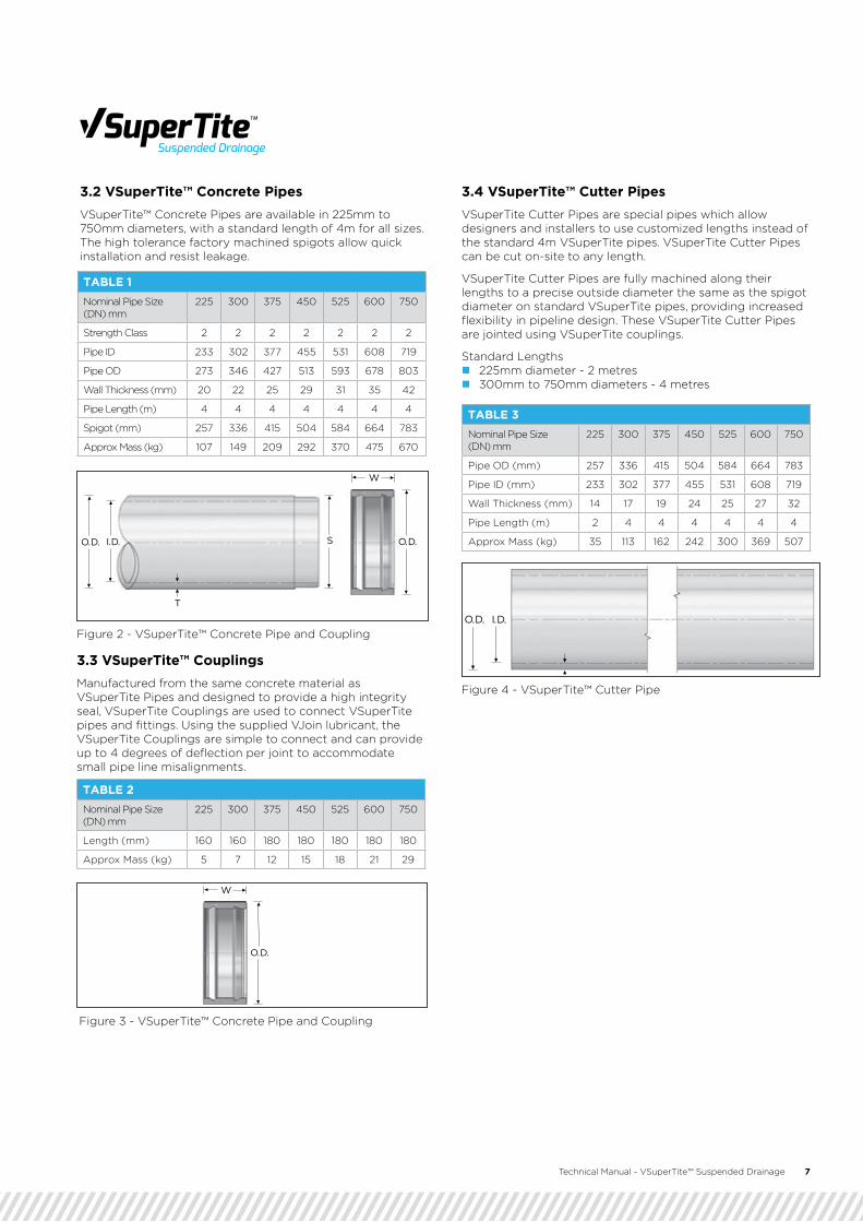
3.2 VSuperTite™ Concrete Pipes VSuperTite™ Concrete Pipes are available in 225mm to 750mm diameters, with a standard length of 4m for all sizes. The high tolerance factory machined spigots allow quick installation and resist leakage.
3.3 VSuperTite™ CouplingsManufactured from the same concrete material as VSuperTite Pipes and designed to provide a high integrity seal, VSuperTite Couplings are used to connect VSuperTite pipes and fittings. Using the supplied VJoin lubricant, the VSuperTite Couplings are simple to connect and can provide up to 4 degrees of deflection per joint to accommodate small pipe line misalignments.
3.4 VSuperTite™ Cutter PipesVSuperTite Cutter Pipes are special pipes which allow designers and installers to use customized lengths instead of the standard 4m VSuperTite pipes. VSuperTite Cutter Pipes can be cut on-site to any length.
VSuperTite Cutter Pipes are fully machined along their lengths to a precise outside diameter the same as the spigot diameter on standard VSuperTite pipes, providing increased flexibility in pipeline design. These VSuperTite Cutter Pipes are jointed using VSuperTite couplings.
Standard Lengths � 225mm diameter - 2 metres � 300mm to 750mm diameters - 4 metres
TABLE 1Nominal Pipe Size (DN) mm
225 300 375 450 525 600 750
Strength Class 2 2 2 2 2 2 2
Pipe ID 233 302 377 455 531 608 719
Pipe OD 273 346 427 513 593 678 803
Wall Thickness (mm) 20 22 25 29 31 35 42
Pipe Length (m) 4 4 4 4 4 4 4
Spigot (mm) 257 336 415 504 584 664 783
Approx Mass (kg) 107 149 209 292 370 475 670
TABLE 3Nominal Pipe Size (DN) mm
225 300 375 450 525 600 750
Pipe OD (mm) 257 336 415 504 584 664 783
Pipe ID (mm) 233 302 377 455 531 608 719
Wall Thickness (mm) 14 17 19 24 25 27 32
Pipe Length (m) 2 4 4 4 4 4 4
Approx Mass (kg) 35 113 162 242 300 369 507
TABLE 2Nominal Pipe Size (DN) mm
225 300 375 450 525 600 750
Length (mm) 160 160 180 180 180 180 180
Approx Mass (kg) 5 7 12 15 18 21 29
W
O.D.
O.D. I.D.
T
W
O.D.SO.D. I.D.
Figure 2 - VSuperTite™ Concrete Pipe and Coupling
Figure 3 - VSuperTite™ Concrete Pipe and Coupling
Figure 4 - VSuperTite™ Cutter Pipe
8 Technical Manual - VSuperTite™ Suspended Drainage
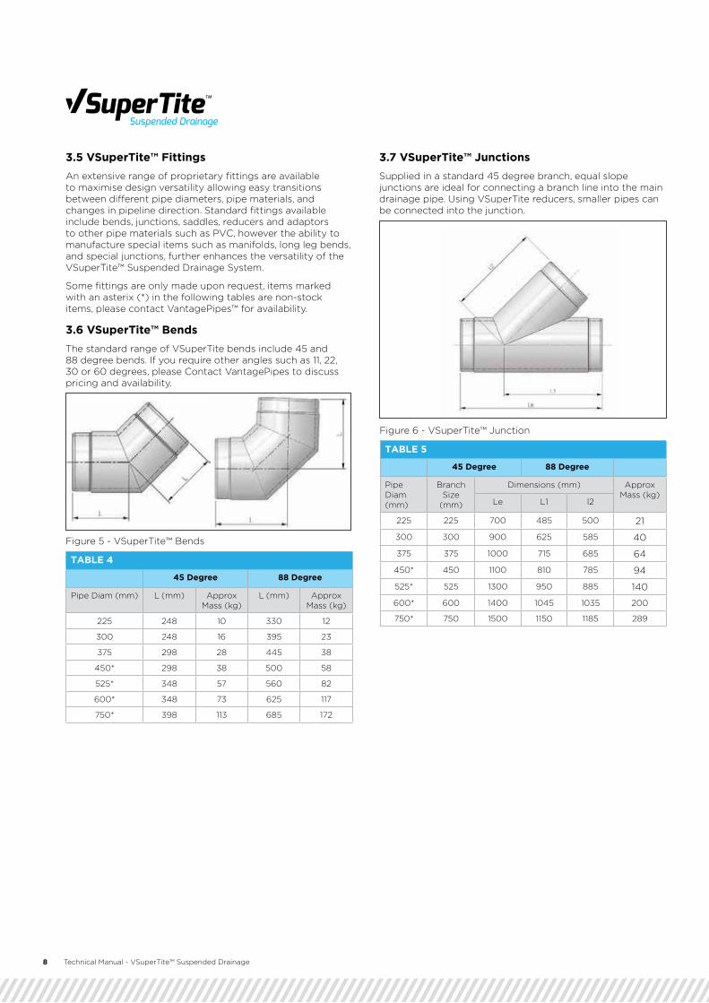
3.5 VSuperTite™ FittingsAn extensive range of proprietary fittings are available to maximise design versatility allowing easy transitions between different pipe diameters, pipe materials, and changes in pipeline direction. Standard fittings available include bends, junctions, saddles, reducers and adaptors to other pipe materials such as PVC, however the ability to manufacture special items such as manifolds, long leg bends, and special junctions, further enhances the versatility of the VSuperTite™ Suspended Drainage System.
Some fittings are only made upon request, items marked with an asterix (*) in the following tables are non-stock items, please contact VantagePipes™ for availability.
3.6 VSuperTite™ BendsThe standard range of VSuperTite bends include 45 and 88 degree bends. If you require other angles such as 11, 22, 30 or 60 degrees, please Contact VantagePipes to discuss pricing and availability.
3.7 VSuperTite™ Junctions Supplied in a standard 45 degree branch, equal slope junctions are ideal for connecting a branch line into the main drainage pipe. Using VSuperTite reducers, smaller pipes can be connected into the junction.
TABLE 4
45 Degree 88 Degree
Pipe Diam (mm) L (mm) Approx Mass (kg)
L (mm) Approx Mass (kg)
225 248 10 330 12
300 248 16 395 23
375 298 28 445 38
450* 298 38 500 58
525* 348 57 560 82
600* 348 73 625 117
750* 398 113 685 172
TABLE 5
45 Degree 88 Degree
Pipe Diam (mm)
Branch Size
(mm)
Dimensions (mm) Approx Mass (kg)
Le L1 l2
225 225 700 485 500 21
300 300 900 625 585 40
375 375 1000 715 685 64
450* 450 1100 810 785 94
525* 525 1300 950 885 140
600* 600 1400 1045 1035 200
750* 750 1500 1150 1185 289
Figure 5 - VSuperTite™ Bends
Figure 6 - VSuperTite™ Junction
3.0 Product Information

Technical Manual - VSuperTite™ Suspended Drainage 9
3.8 VSuperTite™ Saddle Junctions These can be used as an alternative to a VSuperTite Slope Junction where smaller diameter branch lines are used. VSuperTite Saddle Junctions also give the flexibility of installation after the main drainage line has been completed.
3.9 VSuperTite™ Saddle TeesCommonly used for bridge drainage scuppers, VSuperTite™ Saddle Tees allow a vertical inlet pipe directly into the main drainage line. Available to suit a range of inlet pipe materials, the 150mm diameter socket inlet has a rubber V-ring for a high integrity seal.
3.10 VSuperTite™ Adaptors and ReducersTo allow connection between different sizes of VSuperTite™ pipes, or to allow a different material line to be incorporated, there are a range of VSuperTite™ Adaptors and Reducers available as standard. All of the adaptors and reducers feature a rubber ring seal to prevent leakage.
TABLE 6
Saddle Slope Pipe X Branch
Dimensions (mm) Approx Mass (kg)
Le L1 L2
300/225 600 490 585 22
375/225 600 530 640 18
375/300 700 580 700 34
450/225 600 575 695 21
450/300 700 625 755 29
Figure 7 - VSuperTite™ Saddle Junction
Figure 9 - VSuperTite™ Reducer
Figure 8 - VSuperTite™ Saddle Tee
TABLE 7
Adaptor Size Pipe X Branch
Dimensions (mm) Approx Mass (kg)
Le H L2
225/150 350 75 225 6
300/150 350 75 280 8
375/150 350 75 320 9
TABLE 8
Reducer Size Pipe X Branch (mm)
Dimensions (mm)
Le H L2 L3
225/150 PVC 265 162 120 257
300/225 PVC 346 252 120 336
300/225 350 260 120 336
375/300 431 340 120 415
450/375 519 418 120 504
525/450 603 507 120 584
600/525 689 587 120 664
3.0 Product Information

10 Technical Manual - VSuperTite™ Suspended Drainage
3.11 VSuperTite™ Expansion JointsVSuperTite expansion joints are manufactured by VantagePipes™ for use where a cyclic expansion may occur, such as bridge decks or connections between adjacent building structures.
For more information see Section 4.7
3.13 Custom ApplicationsVantagePipes™ can custom design a drainage solution for unique applications that present particular challenges to designers. Some examples of these custom solutions can be found in bridge and tunnel drainage where the stormwater system must be adapted to work with structural components that cannot be altered.
Contact VantagePipes to discuss how the VSuperTite Drainage System can be adapted or customised to suit your specific project.
3.12 VSuperTite Cleanout PointTo allow maintenance access for inspection or rodding of drainage lines, VSuperTite cleanout points can be installed along a suspended pipe where required. Featuring a bitumen coated cast iron access point with a rubber ring seal and secured with 316 stainless steel straps, the VSuperTite cleanout point provides a 100mm access opening that can be oriented at any location around the pipe circumference. VSuperTite cleanout points can be retro-fitted to any drainage pipe line.
Using a 100mm BSP 316 stainless steel threaded plug to seal the opening, the VSuperTite cleanout point provides a simple solution for maintenance access.
Figure 10 - VSuperTite™ Expansion Unit
Figure 11 - Cleanout saddle to 100 BSP
3.0 Product Information

Technical Manual - VSuperTite™ Suspended Drainage 11
3.0 Product Information

4.1 Working PressureThe maximum instantaneous pressure for the VSuperTite™ Drainage System is 250KPa (25m head). Sustained working pressures should be limited to below 90kPa, if a requirement exists for a higher working pressure please Contact VantagePipes™ to discuss your application.
4.2 Connection of non-VSuperTite™ PipesOther pipe materials can be connected to VSuperTite pipes using VSuperTite Slope Junctions, VSuperTite Saddle Tee’s or in-line VSuperTite Adaptors. Commonly connected pipes are PVC, stainless steel or cast iron in nominal diameters of 150 or 225mm. Contact VantagePipes for more information on available adaptors.
4.3 Suspending PipesVSuperTite Suspended Drainage System may be hung from the structure or coupled directly to it. A range of different bracket types can be used to support pipes and fittings however these should be certified by their manufacturer for suitability (see Figure 12). The following table indicates the approximate weight of one 4 metre length of VSuperTite pipe with couplings full of water.
12 Technical Manual - VSuperTite™ Suspended Drainage
Suspended Brackets Close-coupled Bracket
Figure 12 - Typical Pipe Brackets
TABLE 9 Weight of pipe full of water
Nom. PipeDiameter (mm)
Weight of pipeand coupling (kg)
Weight ofwater (kg)SG=1
Total SuspendedWeight per 4m length (kg)
225 93 166 259
300 147 288 435
375 215 447 662
450 281 656 937
525 362 896 1258
600 467 1169 1636
750 657 1629 2286
4.0 Design Information

Technical Manual - VSuperTite™ Suspended Drainage 13
4.4 Horizontal PipesTwo support brackets per length of VSuperTite™ pipe are required. It is usual to support the pipe adjacent to the couplings at either end. Bracketing should directly support all fittings. Bends should have at least one bracket, and junctions at least two.
Where a saddle junction or tee is used, an extra bracket should be installed on the side of the saddle closest to the pipe midpoint if the saddle is located more than one metre from a normal support bracket.
Do not clamp around the coupling or allow the coupling to carry the weight of the pipe, this may affect the seal integrity of the joint.
4.5 Vertical PipesFor nominal diameters 225mm to 750mm, two support brackets per length are required. All fittings should be supported. No special support requirements are needed for saddle junctions in the vertical plane. Where VSuperTite Cutter Pipes are used vertically, a bracket should be placed directly below each coupling.
Notes: For vertical pipes install VSuperTite Concrete Pipes close-coupled directly to the structure whenever possible. If VSuperTite Concrete Pipes are to be suspended from light weight roof structures consisting of “Z” purlins or similar, the structure should be checked for load bearing capacity and deflections by a structural engineer.
VSuperTite Pipe
Support Bracket
VSuperTite Coupling
Support bracket (if required)
Dimensions:A - 250mm +/- 50mmB - Maximum 1000mm, additional bracket on the side indicated required if this is exceeded.
Saddle Tee
4030 Typical
AA
A B
Figure 13 - Horizontal Pipe Support
Figure 14 - Vertical Pipe Support
3.0 Product Information

14 Technical Manual - VSuperTite™ Suspended Drainage
4.6 Resisting Thrust (Bracing)Normal engineering requirements apply to the VSuperTite™ Suspended Drainage System for the restraint of out-of-balance forces generated by internal pressure at changes in pipeline direction.
Unless the pipeline system is close-coupled to the structure, it is good practice to have a lateral brace at approximately 8m intervals (every second joint). If the hanging distance is large, lateral bracing may be required at 4m intervals.
At changes in direction, the forces tabulated in Table 10 must to be transferred to the structure. The methods of bracing vary widely depending on pipeline location, working or test pressure of the pipeline and the type of structure. Solid bracing, or tubular bracing should be used if compression loads need to be transferred to the structure. Threaded rod may be used where tensile loads need to be transferred to the structure. However, it should not be used to transfer compression loads due to the possibility of deflection.
Where several fittings are located near each other (particularly bends), extreme care should be exercised that all forces are transferred to the structure. If doubt exists as to the adequacy of a particular bracing requirement or if more detailed information is required, refer to a reputable bracing manufacturer.
Note: Thrusts are for 5m head at the fitting, loads for other head values can be proportioned linearly. The above thrusts have been calculated ignoring any velocity head and have generally been rounded to the nearest whole number. All dimensions are nominal and may change without notice.
TABLE 10 Thrust force at bends
APPROX.THRUST ONBENDS(Thrust kNper 5m ofhead)
Nominal Pipe Dia
(mm)
45 degree bend
88 degree bend
Tee or closed end
225 3 4 3
300 4 7 5
375 6 10.5 7
450 8 15 10
525 11 21 14
600 14 26 18
675 17 32 23
750 21 37 26
Figure 15 - Typical Bracing Details Figure 16 - Lateral Bracing
3.0 Product Information

Technical Manual - VSuperTite™ Suspended Drainage 15
4.7 Expansion JointsVSuperTite™ Expansion Joints are manufactured by VantagePipes™ for use where a cyclic expansion may occur, such as bridge decks or connections between adjacent building structures. The standard VSuperTite Expansion Joint is manufactured to allow a movement range of 90mm, although this can be varied to suit specific applications. The VSuperTite Expansion Joint functions by using an internal rolling O-ring held between an inner and outer sleeve.
When considering a VSuperTite Expansion Joint, the design of brackets for thrust bracing must be done with careful consideration of the forces required to expand/contract the VSuperTite Expansion Joint. The VSuperTite Expansion Joint must be robustly secured to the adjacent sides of the structure to ensure that the VSuperTite drainage line expands and contracts at the required point (i.e. at the VSuperTite Expansion Joint).If this is not done correctly, there is the potential for the pipeline to become disconnected at another location, causing water leakage and potentially hazardous conditions. Brackets to securely connect VSuperTite Couplings located in close proximity to the VSuperTite Expansion Joint may also be required.
More detail on the installation of the VSuperTite Expansion Joint can be found in Section 6 - Installation.
Figure 17 - Expansion Joint Dimensions
TABLE 11 Expansion Joint Dimensions
Nom. Pipe Diameter (mm)
Dimensions (mm) Approx Mass (kg)
Le min (mm) Le max (mm)
225 860 950 44
300 945 1035 72
375 1040 1130 112
Figure 18 - VSuperTite™ Expansion Joint
3.0 Product Information

16 Technical Manual - VSuperTite™ Suspended Drainage
4.8 Joint DeflectionThe table below shows the maximum recommended rotation at a VSuperTite™ coupling joint for each pipe size, together with the resulting minimum achievable radius curvature and corresponding deflection for each 4 metre length of VSuperTite pipe.
4.9 Hydraulic PerformanceThe consistent, smooth bore of VSuperTite Concrete Pipes provides excellent hydraulic characteristics. To determine hydraulic characteristics the two most common formulae are Mannings and Colebrook-White.
ManningsThe use of the Mannings equation may give reasonable flow estimates for less than full pipe flow, if an allowance is made for the variation of the roughness coefficient with pipe size and flow velocity.
Colebrook-WhiteColebrook-White is a more accurate method for calculations involving VSuperTite pipes that are flowing full. The following Colebrook-White formula and design chart for VSuperTite pipes should allow quick and easy estimates without involved calculations. The formula is derived from the Colebrook equation, Darcy friction factor equations and Reynolds number definition for flow in a pipe to allow solution for V.
Where:
V = cross-sectional average velocity (m/s)n = Manning roughness coefficientS = hydraulic gradient (m/m)Rh = hydraulic radius = A/P (m)A = cross sectional area of flow (m2)P = wetted perimeter (m)D = pipe internal diameter (m)k = hydraulic roughness (m)g = gravitational acceleration (m/s2)= kinematic viscosity of water (m2/s)
Note: This flow chart has been prepared using the Colebrook-White equation where the friction coefficient (f) is determined from the formulae:
Where:Re = Reynolds number
Manning’s ‘n’ may be taken as 0.011 and the ‘Australian Rainfall and Runoff’ publication recommends that the Colebrook-White roughness co-efficient ‘k’ lies in the range 0.015 to 0.060mm.
The chart has been prepared using a (k) value of 0.060mm.Once the average velocity has been established, the discharge formula Q = A.V can be used to estimate the volumetric flow rate (discharge). For the purposes of the following chart, the nominal internal diameters of VSuperTite concrete pipes have been used.
Figure 19 - VSuperTite™ Joint Deflection
TABLE 12 VSuperTite™ Joint Deflection
Nom. Pipe Diameter (mm)
Max. Rotation (degrees)
Min. radius of curvature (m)
Pipe end deflection at 4m (4mm)
225 4.0 57 280
300 4.0 57 280
375 2.5 92 175
450 2.0 115 140
525 1.5 153 105
600 1.0 230 70
750 1.0 230 70
3.0 Product Information

Technical Manual - VSuperTite™ Suspended Drainage 17
3.0 Product Information

5.1 Durability With a history of pipe manufacturing going back to 1926, VantagePipes™ is at the forefront of fibre reinforced concrete composite technology. The Portland cement based concrete constituents of the pipe matrix have a demonstrated performance record of over 80 years.
VSuperTite™ concrete pipes are manufactured with a matrix of high pressure, steam cured (autoclaved) cement and silica. The high pressure steam curing converts the raw materials of the matrix to a calcium silicate hydrate material which has been proven to be highly durable in service. Further to this attribute, as VSuperTite pipes and fittings do not contain any steel, the risk of steel corrosion is not present. VSuperTite pipes and fittings are intended to achieve a 100 year design life when correctly installed.
5.2 Thermal ExpansionVSuperTite concrete pipes have a low linear thermal expansion similar to concrete. This reduces the need for any allowance for differential expansion rates between the VSuperTite concrete pipe and the structure to which it is attached.
Note: Values are indicative only and should not be relied upon for calculation purposes. Please contact VantagePipes Pipes for more information. VSuperTite expansion joints are available where needed, for example when a VSuperTite pipeline passes underneath a bridge deck expansion joint. Consideration must be made for the associated VSuperTite pipe movement.
5.4 Acoustic PropertiesBecause of the excellent acoustic properties of VSuperTite Concrete Pipes, the use of this product in suspended applications significantly reduces hydraulic noise caused by pipeline flow when compared to some other pipe materials. Testing carried out at the Queensland University of Technology showed that the pseudo STC rating for VSuperTite™ Concrete Pipes is 12dB (A) quieter than for PVC pipes. The pseudo STC rating was calculated using measured differences in A-weighted 1/3 - Octave Band Levels at frequencies of 180 Hz and above for radial transmission of sound through each pipe.
A difference of 10dB (A) is equivalent to sound appearing half as loud. Therefore, assuming a constant internal noise source, VSuperTite™ Concrete Pipes are half as loud as PVC pipes.
5.3 Fire ResistanceFire Resistance Levels VSuperTite Concrete Pipes are resistant to damage caused by fire. Pipes that penetrate fire separating elements such as masonry and concrete walls are require to demonstrate fire ratings in accordance with AS1530.4-2005 and AS4072.1-2005.
VSuperTite Concrete Pipes have been assessed as possessing adequate resistance to fire and are suitable for use as service penetrations through fire separating elements, provided certain installation requirements are met. For more information regarding fire resistance of VSuperTite Concrete Pipes, please contact VantagePipes on 1800 659 850.
18 Technical Manual - VSuperTite™ Suspended Drainage
TABLE 12 Indicative Thermal Expansion Values
Indicative linear thermal expansion (10-6 m/m/C°)
Concrete 12
VSuperTite™ pipes 10
Plastic (PVC, HDPE, PE) 50-150
5.0 Material Properties

Technical Manual - VSuperTite™ Suspended Drainage 19
5.0 Material Properties
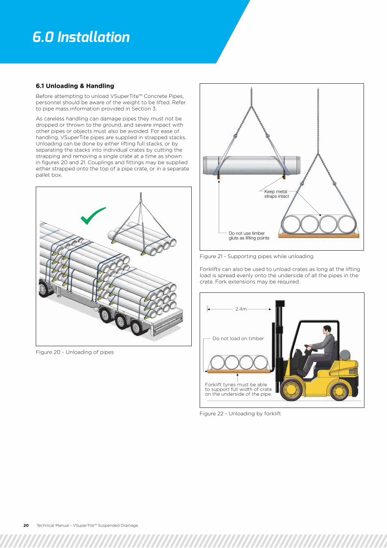
6.1 Unloading & HandlingBefore attempting to unload VSuperTite™ Concrete Pipes, personnel should be aware of the weight to be lifted. Refer to pipe mass information provided in Section 3.
As careless handling can damage pipes they must not be dropped or thrown to the ground, and severe impact with other pipes or objects must also be avoided. For ease of handling, VSuperTite pipes are supplied in strapped stacks. Unloading can be done by either lifting full stacks, or by separating the stacks into individual crates by cutting the strapping and removing a single crate at a time as shown in figures 20 and 21. Couplings and fittings may be supplied either strapped onto the top of a pipe crate, or in a separate pallet box.
Forklifts can also be used to unload crates as long at the lifting load is spread evenly onto the underside of all the pipes in the crate. Fork extensions may be required.
2.4m
Forklift tynes must be ableto support full width of crateon the underside of the pipe.
Do not load on timber
20 Technical Manual - VSuperTite™ Suspended Drainage
Figure 22 - Unloading by forklift
Figure 21 - Supporting pipes while unloading
Figure 20 - Unloading of pipes
6.0 Installation

Technical Manual - VSuperTite™ Suspended Drainage 21
Lifting of VSuperTite™ pipes should be done by appropriately qualified operators using suitably rated lifting equipment. Refer to Section 3 for pipe masses to be lifted. Care should be taken to ensure that the pipe ends are not damaged and worker safety is maintained while moving VSuperTite pipes and fittings around site.
Good handling practice is based on sound judgement and common sense, keeping in mind regard for safety, health and the environment.
Notes
1. VSuperTite concrete pipes are heavy and need to be handled with extreme caution to prevent injury or property damage.
2. When the contractor is unloading it is their responsibility to do so in a safe manner. All necessary risk assessments, hazard identifications, and safe work methods must be implemented.
3. It is not recommended to cut the steel bands bundling the pipe together until safely stored on site. However, if it is necessary to cut the bands while on the truck, please take safety precautions to stabilise the pipe on the pallet and the remaining pipe on the truck.
4. Do not use the timber gluts or beams as lifting points at any time.
5. Contact your local sales representative or ask VantagePipes™ on 1800 659 850 if you are not sure about offloading procedures.
6.2 Storing On-Site VSuperTite pipes, couplings and fittings should be stored properly on site to prevent unnecessary damage. Be sure to keep stored rubber rings out of direct contact with sunlight to prevent the rubber from experiencing UV damage. The storage area must be a level area with a stable base. VSuperTite pipes and fittings should not be stored on sloping ground as shown in Figure 24.
� Pipe stacks can be up to 2.4m high provided: � Pipes must be aligned in the same direction � Stacks must be aligned in the same direction � Stacks must be aligned vertically ensuring the timber
gluts are in line � No cantilevered pipes or crates are allowed
Figure 23 - Proper liftingFigure 24 - Storage on level ground
Figure 25 - Storage on level ground
Note: The above recommendations must be considered in addition to normal industry practice and any specific site OH&S requirements applicable to the safe handling and storage of VSuperTite pipes and fittings.
3.0 Product Information

22 Technical Manual - VSuperTite™ Suspended Drainage
6.3 Preparation As it is essential to be completely familiar with design drawings and specifications, work through the following list before commencing pipe installation:
1. Check that the correct pipes and fittings are stored at the correct locations.
2. Combine and match couplings and rubber rings by diameter and match with the location of the stored pipes.
3. Ensure that VSuperTite™ Cutter Pipes are available for pipe lengths less than full 4 metre lengths.
4. Do not cut VSuperTite Concrete Pipes, use VSuperTite Cutter Pipe for all lengths less than 4m. Refer to Secton 6.5
5. Confirm the locations and types of all thrust resisting bracing.
6. Confirm all testing requirements and whether testing will be done in sections or for the completed system.
7. Draw up a realistic but firm construction schedule.
6.4 Pipeline AssemblyThe VSuperTite Suspended Drainage System is simple to install, requiring no welding, brazing or other specialised techniques. It is good practice to draft the location of the pipeline route so that the pipe support brackets are accurately located and installed before the pipe and fittings are lifted into place.
This allows the weight of the pipe or fitting to be supported by the bracket during the jointing operation.
VJoin LubricantVJoin lubricant is a special compound of soft soap solution that is supplied to facilitate jointing VSuperTite Concrete Pipes with fittings. It is essential that the VJoin lubricant is used and not oil or grease, as these will cause deterioration of the rubber rings. In an emergency, a solution of soap powder and water can be used as a jointing compound. The following table gives the metres of pipe that can be jointed per litre of VJoin lubricant.
VSuperTite™ Coupling InstallationFor ease of installation, VSuperTite couplings may be fitted to one end of the VSuperTite pipe prior to lifting into position, as this leaves only one operation per joint for the installation crew to complete. VSuperTite pipes should be left plain ended where Fittings are to be located.
Figure 26 - Lifting VSuperTite™ Pipes
Figure 27 - VSuperTite™ Coupling Installation
TABLE 12 Pipes jointed per litre of VJoin Lubricant
Pipe Size (mm) Joints Per Litre Metres Per Litre
225 19 80
300 14 60
375 11 48
450 9 40
525 8 36
600 7 32
675 5 24
750 4 20

Technical Manual - VSuperTite™ Suspended Drainage 23
The following procedures should be followed to fit VSuperTite™ couplings to VSuperTite pipes:
1. Check that the VSuperTite coupling is free from dirt and place the rubber ring into the VSuperTite Coupling, ensuring that the V-ring is correctly fitted to the groove in the VSuperTite Coupling.
2. Apply VJoin lubricant to the pipe spigot back to the witness groove.
3. Push on the VSuperTite Coupling back to the witness groove.
4. Use of a pipe jointing tool such as an over-centre puller or winch block may be required to provide the required insertion force. For larger diameter pipes, two jointing tools may be required to keep the pipes centerline in position.
6.5 Cutting PipesIt may be necessary to cut pipes and install fittings at intervals along a pipe length depending on the drainage design. As the ends of VSuperTite Concrete Pipes are machined to the VSuperTite spigot, a standard pipe cannot be cut and jointed with a VSuperTite Coupling. To overcome this VSuperTite Cutter Pipes are available which is machined to the VSuperTite spigot dimension along the full length. This allows the pipe to be cut anywhere along its length and then be jointed with a standard VSuperTite Coupling.
To avoid displacing the VSuperTite V-ring during jointing, after trimming the VSuperTite Cutter pipe to the required length it is necessary to form a chamfer on the end, similar to that of a standard pipe. This chamfer can either be hand filed with a rasp or made with a power-cutting tool. The special length of VSuperTite Cutter pipe may now be jointed as described above.
Figure 28 - VSuperTite™ Pipe Jointing Method
24 Technical Manual - VSuperTite™ Suspended Drainage
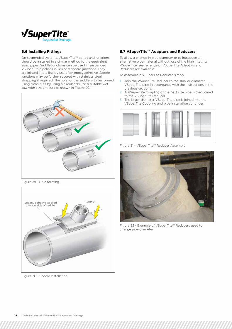
6.6 Installing Fittings On suspended systems, VSuperTite™ bends and junctions should be installed in a similar method to the equivalent sized pipes. Saddle junctions can be used in suspended VSuperTite pipelines in lieu of standard junctions. They are jointed into a line by use of an epoxy adhesive. Saddle junctions may be further secured with stainless steel strapping if required. The hole for the saddle is to be formed using clean cuts by using a circular drill, or a suitable wet saw with straight cuts as shown in Figure 29.
6.7 VSuperTite™ Adaptors and ReducersTo allow a change in pipe diameter or to introduce an alternative pipe material without loss of the high integrity VSuperTite seal, a range of VSuperTite Adaptors and Reducers are available.
To assemble a VSuperTite Reducer, simply
1. Join the VSuperTite Reducer to the smaller diameter VSuperTite pipe in accordance with the instructions in the previous sections.
2. A VSuperTite Coupling of the next size pipe is then joined to the VSuperTite Reducer.
3. The larger diameter VSuperTite pipe is joined into the VSuperTite Coupling and pipe installation continues.
Expoxy adhesive appliedto underside of saddle
Saddle
Figure 29 - Hole forming
Figure 30 - Saddle Installation
Figure 32 - Example of VSuperTite™ Reducers used to change pipe diameter
Figure 31 - VSuperTite™ Reducer Assembly

Technical Manual - VSuperTite™ Suspended Drainage 25
6.8 VSuperTite™ Expansion Joints To ensure correct operation of the VSuperTite expansion joint, the connection between the VSuperTite pipe and expansion joint is different from others along the pipe line.
Both sides of the VSuperTite expansion joint must be rigidly connected to the bridge structure on the correct side of the bridge expansion joint. A suggested design is shown in Figure 33, where the pipe brackets are connected on both sides of the VSuperTite couplings and a solid bracket is used to connect to the bridge structure. Use of a cementitious epoxy to fasten the brackets to the pipe is also recommended.
VSuperTite expansion joints are supplied in a fully closed position, and should be adjusted to the required start position prior to installation depending upon the project requirements.
VSuperTite CouplingTM
TM
Solid connection overthe VSuperTite™ Coupling
VSuperTite™ ExpansionJoint
VSuperTite™ Pipe
Suggested bracket design close coupledto the structure
Bridge expansionjoint
Figure 33 - VSuperTite™ Expansion Joint Installation
7.1 Purpose of TestingThe purpose of testing a VSuperTite™ pipe system is to ensure that the joints and fittings are watertight and that the bracing is capable of resisting the thrust for which it was designed. It is recommended that all testing should be done hydrostatically, as air testing will not give a true test result as there may be some degree of permeation through the pipe wall and joint material. If hydrostatic testing is conducted over a long period of time (in excess of 1 hour), allowance for water absorption into the VSuperTite pipe wall should be made.
Note the restrictions on working pressure in Section 4.1. The manner of testing should be carefully considered as a test requirement in excess of likely working pressures could significantly increase the cost of installation. In most cases, the limiting pressure will be that able to be withstood by the test plug.
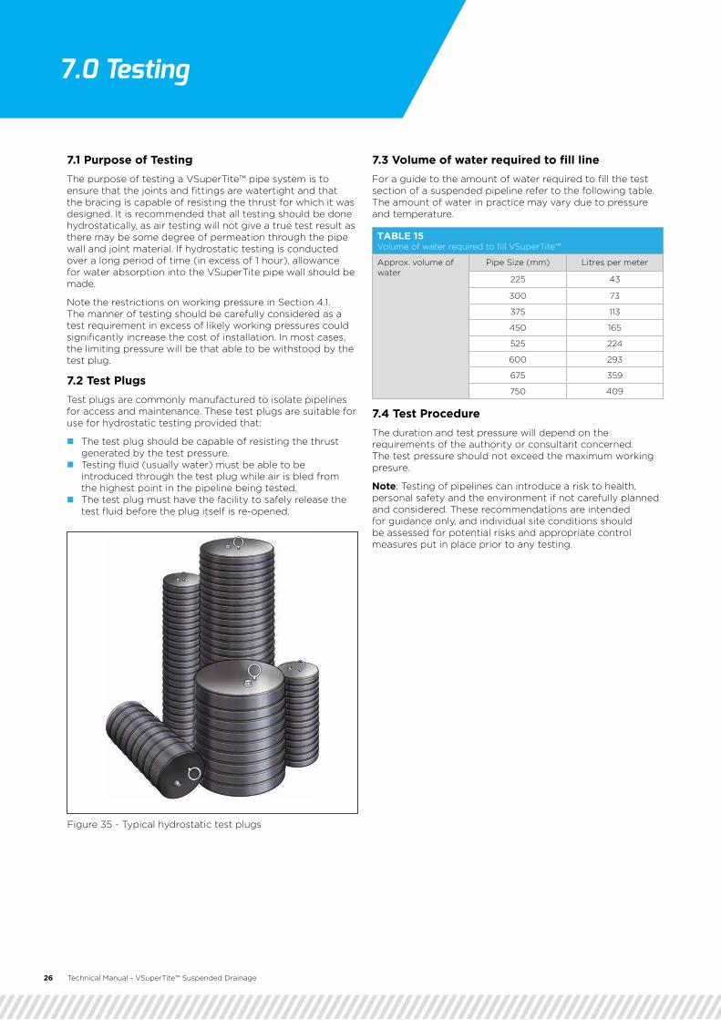
7.2 Test PlugsTest plugs are commonly manufactured to isolate pipelines for access and maintenance. These test plugs are suitable for use for hydrostatic testing provided that:
� The test plug should be capable of resisting the thrust generated by the test pressure.
� Testing fluid (usually water) must be able to be introduced through the test plug while air is bled from the highest point in the pipeline being tested.
� The test plug must have the facility to safely release the test fluid before the plug itself is re-opened.
7.3 Volume of water required to fill lineFor a guide to the amount of water required to fill the test section of a suspended pipeline refer to the following table. The amount of water in practice may vary due to pressure and temperature.
7.4 Test ProcedureThe duration and test pressure will depend on the requirements of the authority or consultant concerned. The test pressure should not exceed the maximum working presure.
Note: Testing of pipelines can introduce a risk to health, personal safety and the environment if not carefully planned and considered. These recommendations are intended for guidance only, and individual site conditions should be assessed for potential risks and appropriate control measures put in place prior to any testing.
26 Technical Manual - VSuperTite™ Suspended Drainage
Figure 35 - Typical hydrostatic test plugs
TABLE 15 Volume of water required to fill VSuperTite™
Approx. volume of water
Pipe Size (mm) Litres per meter
225 43
300 73
375 113
450 165
525 224
600 293
675 359
750 409
7.0 Testing

Technical Manual - VSuperTite™ Suspended Drainage 27
8.0 Warranty
Notes

Technical Manual - VSuperTite™ Suspended Drainage 28
COPYRIGHT AUGUST 2016 © FRCPA PTY LTD t/as VantagePipes ABN 64 605 089 941
08/16
Fast. Smart. Proven. Strong.1800 659 850 | VantagePipes.com.au