technical note t1 basics - mauimauigateway.com/~surfer/library/fundamentals-of-t1.pdf · t1 basics...
TRANSCRIPT

1
T1 Basicstechnical note

2
T1 Basics
hen a technology gains rapid acceptance, it often reaches buzzword status beforethe details are commonly understood. So it is with T1: although it is an importantpart of many communications networks, many of us are still trying to learnthe fundamentals.
WThe objective of this technical note, then, is to provide the reader with basic
information about T1. It starts with a definition and brief history, evolves to describe how thetechnology actually works, and concludes with a summary of the benefits and techniques oftesting T1 networks.
T1 is a digital communications link that enables the transmission of voice, data, andvideo signals at the rate of 1.544 million bits per second (Mbps). Introduced in the 1960s, itwas initially used by telephone companies who wished to reduce the number of telephonecables in large metropolitan areas.
In its early days, the expense of installing T1 made the technology cost-prohibitive formany end users. In fact, the primary user of T1 services outside of the telephone companieswas the federal government. But in the early 1980s, the service was retariffed so that substantialsavings could be realized with the purchase of large amounts of bandwidth. After retariffing, thedemand for T1 increased substantially.
Why is T1 in Demand?The current demand for T1 services can be linked to a number of tangible benefits.
A rudimentary knowledge of electronics as it applies totelephony is assumed.
3
Figure 2:
A communications network with T1
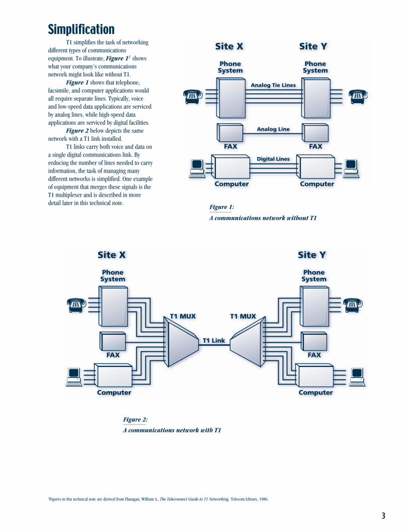
SimplificationT1 simplifies the task of networking
different types of communicationsequipment. To illustrate, Figure 11 showswhat your company’s communicationsnetwork might look like without T1.
Figure 1 shows that telephone,facsimile, and computer applications wouldall require separate lines. Typically, voiceand low-speed data applications are servicedby analog lines, while high-speed dataapplications are serviced by digital facilities.
Figure 2 below depicts the samenetwork with a T1 link installed.
T1 links carry both voice and data ona single digital communications link. Byreducing the number of lines needed to carryinformation, the task of managing manydifferent networks is simplified. One exampleof equipment that merges these signals is theT1 multiplexer and is described in moredetail later in this technical note.
Figure 1:
A communications network without T1
1Figures in this technical note are derived from Flanagan, William A., The Teleconnect Guide to T1 Networking, Telecom Library, 1986.
Analog Tie Lines
FAX
PhoneSystem
Computer
FAX
PhoneSystem
Computer
Analog Line
Digital Lines
Site X Site Y
T1 Link
T1 MUX
FAX
PhoneSystem
Computer
FAX
PhoneSystem
Computer
Site X Site Y
T1 MUX

4
The 64 kbps DS0 rate is obtainedby multiplying the number ofsamplings per second (8,000) bythe number of bits in eachsample (eight).
F
EconomyT1 is extremely economical for
organizations with high traffic volumes. Asan example, Figure 3 depicts a multilinecorporate network between Dallasand Denver.
In 1985, the monthly operating costsof the network shown in Figure 3 wereapproximately $27,000.
Using a T1 link to eliminate theexpense of separate lines as shown inFigure 4 on the next page, monthlyoperating costs decreased by approximately$7,000 per month, or $85,000 per year. Andsince 1985, the tariffs have moved even morefavorably toward T1 usage. The yearly savingson operating costs for this corporate networkhave since increased to over $150,000.2
In addition to cost savings, the T1model shown in Figure 4 provides plenty ofbandwidth for future expansion with noincreased transmission costs.
Signal QualityT1 also provides a signal which is
consistently superior in quality to thatprovided by analog facilities. Analog circuitsamplify noise and distortion to levels that can
FAX
FEP
CPU
Dallas
CPU
PBX
56k DDS56k DDS
56k DDS56k DDS
Denver
Term Cont
Term Cont56k DDS
9600
9600
9600
9600
FAX
PBX
9600
10 Voice Tie Lines
CADApplication
InteractiveBSC Application
AsyncContentionApplication
FAXApplication
VoiceApplication
Figure 3:
A multilinecorporate network
2Flanagan, William A., The Teleconnect Guide to T1 Networking, Telecom Library, 1986.
impair voice and severely degrade dataservice. But T1 regenerates the original signalwithout the noise and distortion at variouspoints along the links.
How T1 Works –Making Voiceand DataCompatible
Many benefits of T1 are attributable tothe fact that voice and data transmitted over asingle digital communications link. Sincecomputer data consists of ones and zeros (thesymbols of the binary system), it is alreadycompatible with T1’s digital format. However,because voice signals are actually complexanalog waveforms, they must be digitized toachieve compatibility with T1.
Pulse CodeModulation (PCM)
The most common method ofdigitizing analog voice signals is a techniquecalled PCM. It is a sampling process thatcompresses a voice conversation into a64 kbps standard rate known as digitalsignal-level zero (DS0).
PCM is actually a two-step technique.In the first step, the incoming analog signal issampled 8,000 times per second, a ratesufficient to adequately represent voiceinformation. These sample values are thenconverted to pulses using a process known aspulse amplitude modulation (PAM), as shownin Figure 5.
In the second step, the height of eachpulse is assigned an equivalent eight-bitbinary value (see Figure 6). The resultingoutput is a digital representation of the pulseand, by extension, the sampledanalog waveform.

5
Figure 4:
A multiline corporate network with T1
*01110111010101010100010000110011001000100001000100000000100110011010101010111011110011001101110111111111
8,000 samples/second x 8 bits/sample = 64 kbps
*For example only, not actual bit values
Figure 5:
Pulse amplitude modulation
Figure 6:
Assigning binary values to pulses
FAX
FEP
CPU
Dallas
CPU
PBX
56k
Denver
Term Cont
Term Cont
9600
FAX
PBX
CADApplication
InteractiveBSC Application
AsyncContentionApplication
FAXApplication
VoiceApplication
T1
T1 MUX T1 MUX
96009600
9600
56k
56k56k
56k
9600
10 Voice Tie Lines 10 Voice Tie Lines
56k
56k
56k56k
56k
9600
9600
9600
9600
9600

6
Figure 7:
Time division multiplexing
Figure 8:
A T1 frame
Time DivisionMultiplexing (TDM)
Once digitized, voice and/or datasignals from many sources can be combined(i.e., multiplexed) and transmitted over asingle T1 link. This process is made possibleby a technique called TDM.
TDM divides the T1 link into 24discrete 64 kbps timeslots. An identicalnumber of DS0 signals (representing 24separate voice and/or data calls) is assignedto each timeslot for transmission within thelink as shown in Figure 7.
In addition to being criticaloperational techniques, PCM and TDM arealso key to understanding the basic T1 rateof 1.544 Mbps.
PCM
Data
1
T1 LinkPCM
TDM
24Data
1
24
TDM
1.544 Mbps ExplainedIn T1, the eight-bit digital samples
created in the PCM step (for voice trafficonly) are grouped into the 24 discrete DS0timeslots created by TDM. Each group of 24timeslots is called a T1 frame (see Figure 8).Since each timeslot contains eight bits, thenumber of information bits within each frametotals 192 (24 x 8). Additionally, a 193rd bitis added to mark the end of one frame andthe beginning of the next. Appropriatelyenough, this added bit is called theframing bit.
Since the DS0 signals are sampled8,000 times per second, it means that 8,000192-bit information frames are created duringthat period. Total: 1.536 Mbps. At 8,000samples per second, framing bits are createdat the rate of 8 kbps. Result: a single 1.544Mbps signal known as digital signal-level one(DS1). See Table 1 on how to calculate the1.544 Mbps rate.
One frame = 24 eight-bit words (192 kbps)plus one framing bit (8 kbps)
1 8 Word
1
Framing Bit
24
Signal RegenerationAny newly created DS1 signal begins
strongly, but degrades (i.e., attenuates) as itprogresses along the T1 link. Such attenuationis usually the result of line noise caused byinterference from other electrical sources. Tocompensate for these negative effects, devicescalled regenerative repeaters sample andrecreate the original signal at periodicintervals along the link as shown in Figure 9.
Since the digital signal consists ofonly two basic values (one and zero),recreating it is not a complicated matter. Insimple terms, a regenerative repeater samplesthe signal input, determines if the inputrepresents a one or a zero, and recreateseach value accordingly. Since line noisedeviates from the standard format of the DS1signal, it is discarded. In this way, aregenerative repeater produces a “clean”replica of the original signal.

7
1 The eight-bit digital samples created 24 samplesby PCM (for voice signals only) are x 8 bits per samplegrouped into the 24 discrete 192 information bits per frametimeslots created by TDM. Each groupof 24 timeslots is called a T1 frame.
2 A framing bit is added to mark the end 192 information bitsof one frame and the beginning of + 1 framing bitthe next. 193 total bits per frame
3 T1 frames are transmitted at the rate 8,000 samplesof 8,000 per second. x 193 total bits
1,544,000 bits per second (1.544 Mbps)
Pulse Code Modulation (PCM) 1. Samples the incoming analog signals 8,000 times per second andconverts the sampled values to pulses.
2. Assigns the height of each pulse an equivalent eight-bit digital value.3. Creates a 64 kbps DS0 signal (8,000 samples per second multiplied
by eight bits).
Time Division Multiplexing (TDM) Combines 24 DS0 signals to create a single 1.544 Mbps signal (DS1)
Signal Regeneration Recreates the 1.544 Mbps signal at prescribed intervals along thetransmission path.
Table 1:
Calculating the 1.544 Mbps T1 rate
Table 2:
How T1 works
Figure 9:
Signal regeneration
Step What Happens Calculation
Signal
TDM
Noise
RegenerativeRepeaters
The number of regenerative repeatersthat may be required along the path of the T1link varies with the type of transmission mediaused. For example, copper wire (a commonshort-haul metallic medium) is highly proneto signal attenuation: thus, repeaters arenormally required at 6,000-foot intervals. Bycontrast, fiber optic cable is a long-haulmedium with low potential for attenuation; assuch, repeaters are spaced at 30-mileintervals. Table 2 explains how T1 works.
Appendix A on page 18 describes thecharacteristics of a wide variety of T1transmission media in detail.
Process What Happens

8
The DS1Signal Format
The DS1 signal is transmitted on theT1 link in a binary format (ones and zeros).The ability to recognize the proper format ofthe DS1 signal is why regenerative repeaterscan distinguish valid input from line noise.As an example, Figure 10 depicts a formatwhich is very commonly used over metallictransmission media (e.g., twisted pair cable,copper wire, etc.): alternate markinversion (AMI).
In the AMI signaling format, the binaryvalue of one is represented by a square wave(i.e., pulse); the binary value of zero isrepresented by a straight line (i.e., theabsence of a pulse).
Each pulse alternates betweenpositive and negative polarity,making the signal bipolarin format.
The primary advantage of the bipolarformat is that it allows the DS1 signal to traveltwice as far on a pair of copper wires.Another advantage of the bipolar format is itsability to offer a built-in method of errordetection. When consecutive pulses of thesame polarity are detected, it constitutes abipolar violation (BPV). BPVs indicate thatsignal input has been disrupted due todefective equipment or poor environmentalconditions (e.g., storms).
B8ZS, Signal Timing,and Ones Density
To correctly identify DS1 input, theregenerative repeater must know when tosample the bipolar signal to determinewhether a one or a zero is being transmittedat any given time. To ensure proper sampling,the repeater relies on a timing method thatuses the binary pulses (i.e., ones) to maintainsynchronization with the network equipmentthat is transmitting the DS1 signal.
Figure 10:
Alternate mark inversion
0 0 1 1 0 1 0 0 0 1
-3 Volts
0 Volts
+3 Volts
Since pulses are critical tomaintaining proper signal timing, all DS1signals are required to meet specific onesdensity standards. These standards requirethat at least one pulse by transmitted withinany eight-bit sequence (i.e., 12.5% onesdensity). Further, since long strings ofconsecutive zeros between digital values canalso hinder signal timing, ones densitystandards prohibit the transmission of morethan 15 zeros in succession.
Success in meeting ones densityrequirements can vary based on application.For example, since the size and content of thebit patterns that represent human speech areconsistent, acceptable ones density in voiceapplications is a virtual certainty. But sincecomputer data is highly variable in size andcontent, conformance to ones densitystandards cannot always be guaranteed. Thistechnical problem is why a coding techniqueknown as bipolar with 8-zero substitution(B8ZS) has gained in popularity.
B8ZS uses intentional BPVs to breakup long strings of zeros, allowing theirtransmission through the T1 link withoutviolating the ones density standard.Figure 11 on the next page shows howB8ZS works.
With B8ZS, network equipmentreplaces any string of eight consecutive zeroswith two intentional BPVs before the DS1signal is transmitted over the T1 link: the firstBPV replaces the fourth zero; the secondreplaces the fifth and seventh zeros.Additionally, the eighth zero bit, whichnormally would be coded as a zero, isassigned a pulse value.
Using this format, the DS1 signal canpass through the repeaters on the T1 link withan acceptable level of pulse density. When thesignal arrives at the receiving networkequipment, the pattern shown in Figure 11is recognized as the B8ZS substitute foreight consecutive zeros; the equipment thenreplaces the intentional BPVs with theirzero values.
DS1 FramingThe bits in the 1.544 Mbps DS1 signal
are meaningless unless they are organized inan orderly, understandable way. Framingprovides this organization (see Table 3).
A frame contains one sample (byte)from each of the DS1’s 24 timeslots. Framingbits separate the frames and indicate theorder of information arriving at thereceiving equipment.
Although most standard T1 networksuse framing, the pattern of the frame can varydepending on the sophistication of theequipment that is sending and receiving theDS1 signal. The sections that follow describetypical DS1 framing patterns starting with themost simple: the D1 frame.

9
Table 3:
D1 framing organization
1
Substituted Byte
BPVBPV
Line Signal
Data Sent
Bit Positions 1 2 3 4 5 6 7 8
1 0 0 0 0 0 0 0 0 0 1
Figure 11:
Bipolar with 8-zero substitution
One to seven of each eight-bit word The customer’s digitized voice or computer data.
Eight of each eight-bit word Signaling information that controls call set up and routing.
193 of each frame The boundary between the end of one frame and the beginningof the next.
Bit(s) Contain(s)
The D1 FrameShown in Figure 12, D1 was the first
framing pattern to be used in T1 transmission.A D1 frame contains 24 timeslots,
each carrying an eight-bit word, with onebit serving as a framing boundary(24 x 8 + 1 = 193). In the D1 framing
Figure 12:
D1 framing pattern
24 eight-bit bytes (192 kbps)
1 8 Word
1
Framing Bit
24
Eight-bit ByteSignaling Information
pattern, bits one to seven of each eight-bitword are reserved for customer information(e.g., digitized voice), bit eight of each wordis reserved for signaling information (i.e., callset up and routing), and bit 193 serves as theboundary between the end of one frame andthe beginning of the next.
The D1 framing format can certainlysimplify framing and signaling managementfor T1 networks with older, unsophisticatedequipment. Unfortunately, D1 is also veryinefficient: reserving one bit in every eight-bitword for signaling can degrade a voice signalto levels below toll quality.
10
Control Bit
Frame 1 •••Frame 2 Frame 3 Frame 11 Frame 12
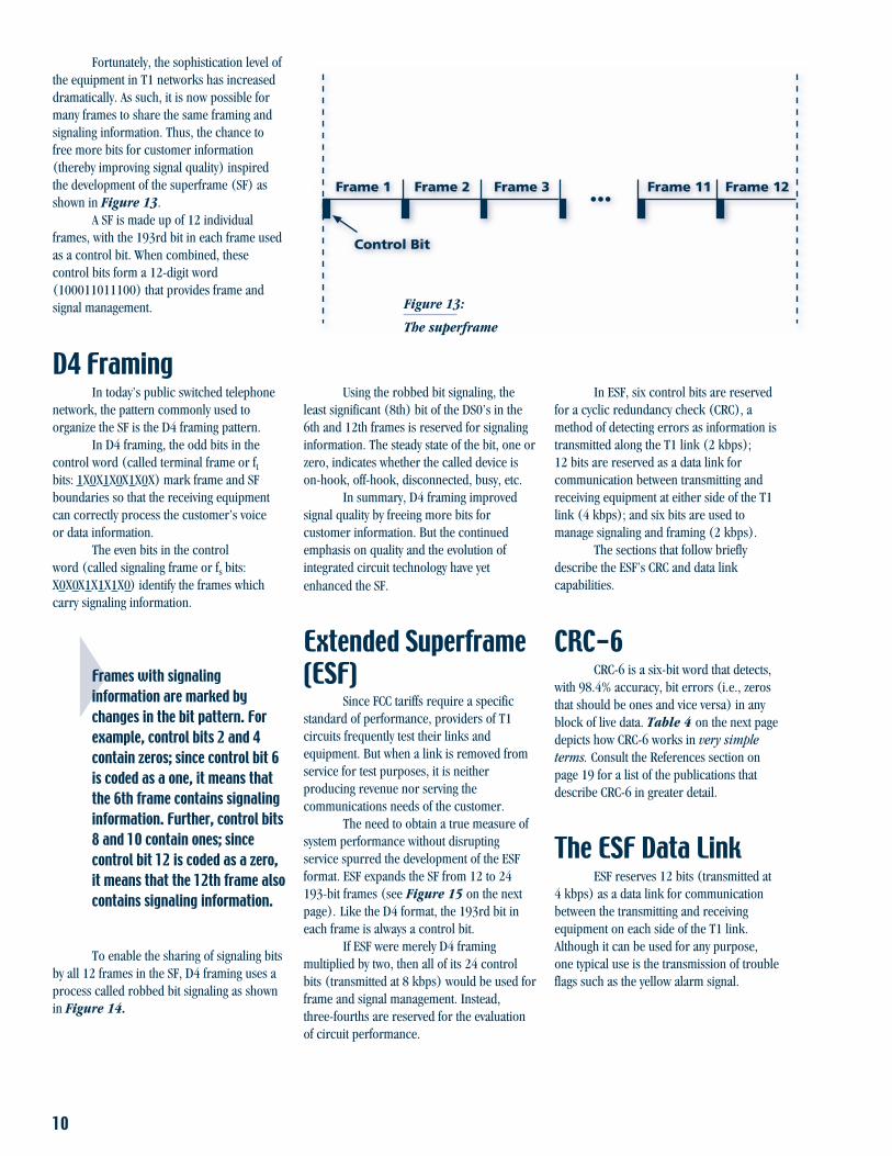
Fortunately, the sophistication level ofthe equipment in T1 networks has increaseddramatically. As such, it is now possible formany frames to share the same framing andsignaling information. Thus, the chance tofree more bits for customer information(thereby improving signal quality) inspiredthe development of the superframe (SF) asshown in Figure 13.
A SF is made up of 12 individualframes, with the 193rd bit in each frame usedas a control bit. When combined, thesecontrol bits form a 12-digit word(100011011100) that provides frame andsignal management.
D4 FramingIn today’s public switched telephone
network, the pattern commonly used toorganize the SF is the D4 framing pattern.
In D4 framing, the odd bits in thecontrol word (called terminal frame or ftbits: 1X0X1X0X1X0X) mark frame and SFboundaries so that the receiving equipmentcan correctly process the customer’s voiceor data information.
The even bits in the controlword (called signaling frame or fs bits:X0X0X1X1X1X0) identify the frames whichcarry signaling information.
Frames with signalinginformation are marked bychanges in the bit pattern. Forexample, control bits 2 and 4contain zeros; since control bit 6is coded as a one, it means thatthe 6th frame contains signalinginformation. Further, control bits8 and 10 contain ones; sincecontrol bit 12 is coded as a zero,it means that the 12th frame alsocontains signaling information.
To enable the sharing of signaling bitsby all 12 frames in the SF, D4 framing uses aprocess called robbed bit signaling as shownin Figure 14.
Figure 13:
The superframe
Using the robbed bit signaling, theleast significant (8th) bit of the DS0’s in the6th and 12th frames is reserved for signalinginformation. The steady state of the bit, one orzero, indicates whether the called device ison-hook, off-hook, disconnected, busy, etc.
In summary, D4 framing improvedsignal quality by freeing more bits forcustomer information. But the continuedemphasis on quality and the evolution ofintegrated circuit technology have yetenhanced the SF.
Extended Superframe(ESF)
Since FCC tariffs require a specificstandard of performance, providers of T1circuits frequently test their links andequipment. But when a link is removed fromservice for test purposes, it is neitherproducing revenue nor serving thecommunications needs of the customer.
The need to obtain a true measure ofsystem performance without disruptingservice spurred the development of the ESFformat. ESF expands the SF from 12 to 24193-bit frames (see Figure 15 on the nextpage). Like the D4 format, the 193rd bit ineach frame is always a control bit.
If ESF were merely D4 framingmultiplied by two, then all of its 24 controlbits (transmitted at 8 kbps) would be used forframe and signal management. Instead,three-fourths are reserved for the evaluationof circuit performance.
In ESF, six control bits are reservedfor a cyclic redundancy check (CRC), amethod of detecting errors as information istransmitted along the T1 link (2 kbps);12 bits are reserved as a data link forcommunication between transmitting andreceiving equipment at either side of the T1link (4 kbps); and six bits are used tomanage signaling and framing (2 kbps).
The sections that follow brieflydescribe the ESF’s CRC and data linkcapabilities.
CRC-6CRC-6 is a six-bit word that detects,
with 98.4% accuracy, bit errors (i.e., zerosthat should be ones and vice versa) in anyblock of live data. Table 4 on the next pagedepicts how CRC-6 works in very simpleterms. Consult the References section onpage 19 for a list of the publications thatdescribe CRC-6 in greater detail.
The ESF Data LinkESF reserves 12 bits (transmitted at
4 kbps) as a data link for communicationbetween the transmitting and receivingequipment on each side of the T1 link.Although it can be used for any purpose,one typical use is the transmission of troubleflags such as the yellow alarm signal.

11
Table 4:
How CRC-6 works
185 186 187 188 189 190 191 192
Signaling Frame B
Signaling Frame AA
B
Voice/DataA
B
Least Significant
100011011100
123456789
101112
1 Superframe= 12 Frames
F
Voice/Data
1 2 3 4 5 6 7 8
Timeslot 1
••••••
Timeslot 24
Control Bit
Frame 1 •••Frame 2 Frame 3 Frame 23 Frame 24
1 The network equipment building the ESF performs a mathematical calculation onthe signal to be transmitted across the T1 link. (Control bits are excluded fromthe calculation.)
2 The signal is transmitted across the T1 link to the receiving equipment. The resultof the mathematical calculation is a six-bit word which is sent to the receivingequipment in the six CRC bit positions of the next ESF.
3 The receiving network equipment performs the same mathematical calculation onthe customer information, and compares the results with the six-bit word whicharrives in the next ESF.
4 If the results match, it is likely that no bit errors have occurred; if the results do notmatch, it indicates that one or more logic errors have occurred, either in thecustomer information or in the CRC bits.
Step Activity
Figure 14:
Robbed bit signaling
Figure 15:
The extended superframe

12
The yellow alarm signal is sent by thereceiving equipment when synchronization toa transmitted DS1 signal cannot be achieved.The yellow alarm is a continuous 16-bitpattern of eight consecutive ones followed byeight consecutive zeros.
The yellow alarm signal is onlyone example of how a data linkcan be used. Consult theReferences section on page 19for a list of publications thatdescribe other uses for thedata link.
ESF’s EnhancedSignaling Capability
In addition to circuit management,ESF also provides enhanced signalingcapability. By robbing the eighth bit from the6th, 12th, 18th, and 24th frames (signalingbits A, B, C, and D, respectively) in the SF,more than 16 signaling states can berepresented. Enhanced signaling capability isessential for emerging services such as video,where signaling states beyond the few used invoice service may be required.
CSUCSU
FAX
FEP
CPU
Dallas
CPU
PBX
56k
Denver
Term Cont
Term Cont
9600
FAX
PBX
CADApplication
InteractiveBSC Application
AsyncContentionApplication
FAXApplication
VoiceApplication
T1 Link
T1 MUX T1 MUX
96009600
9600
56k
56k56k
56k
9600
10 Voice Tie Lines 10 Voice Tie Lines
56k
56k
56k56k
56k
9600
9600
9600
9600
9600
Figure 16:
A simple T1 circuit
T1 Equipment –A SimpleT1 Circuit
T1 networks are composed of manydifferent types of equipment, each with aunique role in making the technology work.The equipment that is required in any givenT1 network is often based on what thenetwork is designed to do. As an example,a simple private T1 circuit is shown inFigure 16.
The circuit is specificallydedicated to connecting thecorporate offices in Dallas andDenver (previously shown inFigures 3 and 4 on pages 4and 5, respectively).
T1 circuits like the ones shown inFigure 16 contain three general equipmenttypes: terminating equipment, user interfaceequipment, and transmission equipment.
Terminating equipment primarilyserves to build the DS1 signal from voice anddata signals of various subrates. (Terminatingequipment is where PCM and TDM are
performed.) This type of equipment also“unbuilds” (i.e., demultiplexes) the DS1 andreturns voice and data signals to their originalsubrates at the receiving end. Examples ofterminating equipment include channel banksand T1 multiplexers. A description of eachtype is provided in Table 5.
User interface equipment connectsterminating equipment with the T1 link, andensures that both ends of the link send andreceive a high-quality DS1 signal. As such,user interface equipment checks forconformance to ones density standards,corrects BPVs, detects yellow alarms,determines AMI or B8ZS signal formatting,and performs CRC-6 calculations (ESFframing only). One common type of userinterface equipment that performs all of thesefunctions is the channel service unit (CSU).
Transmission equipment is thephysical media used to carry DS1 information.Examples include twisted pair, coaxial, fiberoptic cables, and satellite and microwavelinks. Appendix A on page 18 describesseveral types of transmission media in detail,including repeater requirements.
A Public T1 NetworkAlternatively, the corporate offices in
Dallas and Denver can also communicatethrough a public T1 network as shown inFigure 17. Available from a variety ofproviders, a public T1 network differs fromthe dedicated T1 circuit in that it is sharedby many users.

13
Channel Bank A simple device typically used in T1 voice applications. Converts analog voice todigital code (i.e., PCM) and combines 24 such calls on a single DS1 signal (i.e.,TDM). “Unbuilds” (demultiplexes) the DS1 signal and returns the voice signal toits original analog state at the receiving end.
T1 Multiplexer Sophisticated termination equipment used in both voice and data applications. Inaddition to performing the functions associated with the channel bank, the T1multiplexer also offers opportunities for network and bandwidth management.
Network Management: A company allocates more individual lines to its phonesystem during peak calling hours and later reassigns the capacity to its computersystem for file transfers.
Bandwidth Management: A company customizes T1 bandwidth toallocate a single 768 kbps timeslot for video conferencing. The remaining 768kbps is divided into 12 64 kbps timeslots for standard voice and data transmission.Total: 1.544 Mbps (1.536 kbps plus 8 kbps for framing and signaling).
Table 5:
T1 circuit equipment
Equipment Description
CSU
CSU
FAX
FEP
CPU
Dallas
CPU
PBX
56k
Denver
Term Cont
Term Cont
9600
FAX
PBX
CADApplication
InteractiveBSC Application
AsyncContentionApplication
FAXApplication
VoiceApplication
T1 MUX
T1 MUX
96009600
9600
56k
56k56k
56k
9600
10 Voice Tie Lines
10 Voice Tie Lines
56k
56k
56k56k
56k
9600
9600
9600
9600
9600
NIU
OfficeRepeater DSX-1 DCS
T1 Network
OfficeRepeater DSX-1 DCS
NIU
CustomerPremises
Equipment
LocalLoop Central Office
Central Office
CustomerPremises
Equipment
LocalLoop
Figure 17:
A public T1 network

14
In the switched T1 network,equipment is divided into categories basedon location: the customer premise (CPE), thelocal loop, and the central office (CO)equipment. The local loop and CO equipmentare described in Table 6.
CPE is so named simply because theorganization connected to the public T1network (e.g., a hospital or corporation) isresponsible for it. As the responsible party,the organization must ensure that itsequipment provides a healthy DS1 signal tothe public T1 network. The equipment on thecustomer premise typically consists of a T1multiplexer and a CSU (i.e., terminatingand user interface equipment, respectively).Both operate exactly as they do in thededicated T1 circuit.
Local loop equipment essentiallyserves to connect the customer with the CO.The local loop is also where the telephonecompany assumes responsibility for theswitched T1 network.
CO equipment connects the DS1signals of many customers and routes trafficthrough the T1 network based on finaldestination. This type of equipment can alsoserve as a test access point for various DS1signal requirements. Examples of switchingequipment are digital cross-connect systems(DCS) and digital signal cross-connect patchpanels (DSX).
Table 6:
Public T1 network equipment
Local LoopNetwork Interface The point where customer equipment ends and network equipmentUnit (NIU) begins. Test access facility for network technicians. Also called smart jack.
CO
Office Repeater Provides simplex current for all the repeaters on the T1 link. Regeneratesthe DS1 signal before routing takes place.
DSX Manual patch panel that primarily serves as a test access point forDS1 signals.
DCS Electronic switch that “unbuilds” the DS1 and reframes each DS0 basedon routing. Also serves as a test access point for DS0 and DS1 signals.
Equipment Description
T1 TestingWhether public or private, T1 circuits
and network equipment must be properlytested and maintained to perform tomaximum efficiency. Accordingly, all T1testing falls under one of two prescribedcategories: out-of-service testing andin-service monitoring.
Out-of-ServiceTesting
Out-of-service testing is so namedbecause live traffic must be removed from theT1 link before testing can begin. In its place,a test instrument transmits a specific datapattern to a receiving test instrument that“knows” the sequence of the pattern beingsent. Any deviations from the transmittedpattern are then counted as errors by thereceiving instrument.
Out-of-service testing can beconducted on a point-to-point basis or bycreating a loopback. Point-to-point testing isa general practice, and requires two testinstruments (one at either end of the T1 link,as shown in Figure 18).
By simultaneously generating a testdata pattern and analyzing the received datafor errors, the test instruments can analyzethe performance of the link in bothdirections.
Loopback testing is often used as a“quick check” of circuit performance orwhen isolating faulty equipment. Figure 19shows how loopback testing works.
In loopback testing, a single testinstrument sends a loop-up code to thefar-end CSU before data is actuallytransmitted. The loop-up code causes alltransmitted data to be looped back towardthe test instrument. By analyzing the receiveddata for errors, the test instrument measuresthe performance of the link up to andincluding the far-end CSU.
Because loopback testing onlyrequires a single test instrument (and, thus,only one operator), it is very convenient.However, loopback testing is limited in thatit can only analyze the combined performanceof both directions of the link. As such, it isextremely difficult to determine whethererrors are originating on the transmit or thereceive side of the T1 link at any given time.
As out-of-service methods, bothpoint-to-point and loopback tests allowdetailed measurements of any T1 link.However, since all out-of-service testingrequires that live, revenue-generating trafficbe interrupted, it is impractical for long-termtesting. Thus, this type of testing is typicallyperformed when a circuit is initially installedor when errors are discovered whenmonitoring live data.

15
CSU
T1 Link
TDM TDM
XX
TestInstrument
CSU
XX
TestInstrument
MUX
CSU
T1 Link
MUX
XX
XX
Loop Code
CSU
TestInstrument
Loopback
Figure 18:
Point-to-point testing
Figure 19:
Loopback testing
DCS
CSU
Typical Access Points
ChannelBank
31 2 4 5
CSURegenerative
Repeaters
Figure 20:
In-service monitoring
In-ServiceMonitoring ofLive Data
The in-service method allows live datato be monitored at various access pointswithout disturbing revenue-generating trafficas shown in Figure 20.
Since in-service monitoring does notdisrupt the transmission of live traffic, it ismore suitable for routine maintenance thanout-of-service testing. Additionally, in-servicemonitoring indicates performance underactual operating conditions. But its primarydisadvantage is that its measurements maynot be as precise as those available inout-of-service testing. What’s more, somenetwork equipment may deter traditionalin-service error measuring.
16
What Can YouMeasure?
Choosing in-service monitoring orout-of-service testing at any given time oftendepends on knowing which measurementsare available in each method. Table 7 offersa summary of the basic T1 test measurementsand their associated limitations.
Typical Test ScenariosThe measurements described in
Table 7 can be performed in a variety of testscenarios. Here is a brief summary of the fourscenarios where T1 testing is typicallyrequired.
1. Installing a T1 link. When installing aT1 link, out-of-service testing is very usefulfor verifying equipment operation andpoint-to-point transmission quality. Startby testing the T1 link independent of otherequipment. Then, after establishing thecircuit point-to-point, loopback each CSUto ensure that they respond to bothloop-up and loop-down codes. Finallyadd terminating equipment to yourtest configuration.
2. Acceptance testing. When completinginstallation testing, stress tests andlong-term tests should be performed toensure that the T1 link is operating withinrelevant specifications. Stress testing isperformed by transmitting patterns thatsimulate minimum ones density andexcess zero requirements through T1equipment and monitoring the outputfor errors. Long-term testing detectstime-related or intermittent errors usingdata patterns which simulate live data.(One such pattern, the quasi-randomsignal source (QRSS) is designedspecifically for this purpose). It isrecommended that long-term testing beperformed over a 24- or 48-hour period.
3. Routine preventive maintenance.Once the T1 circuit is installed, routinemaintenance can indicate degradingservice before it disrupts normaloperation. Preventive maintenance isusually performed in-service, and involvesmonitoring live data for BPVs, frameerrors, and CRC errors. These tests shouldalso be performed over a 24- or 48-hourperiod to detect time-specific orintermittent errors.
4. Fault isolation. Fault isolation isrequired once excessive error rates havedisrupted service. In-service monitoringis recommended to localize problemsand minimize circuit downtime. Bymonitoring the circuit at various points,you can analyze the results and discoverwhere problems are originating. Byperforming standard out-of-service tests(i.e., loopback and point-to-point tests),technicians can identify the problem,isolate the faulty equipment, and verifyproper operation once the problemis solved.

17
Bit Errors
BPVs
Frame Errors
CRC Errors
Measurement Description Available Prime Advantage Prime Disadvantage
The basic performanceevaluator; counts thenumber of logic errorsin the bit stream (i.e.,zeros that should beones and vice versa).Provides specific errormeasurements.
A measure of thenumber of times pulsesof the same consecutivepolarity were transmit-ted across the T1circuit, in violationof the bipolar signalformat. Providesapproximate biterror rate.
Measures the number oftimes an incorrect valueappears in a bit positionreserved for framing(i.e., 193rd bit).Provides approximatebit error rate.
Detects one or morebit errors in a blockof data.
Out-of-serviceonly.
In-service orout-of-service.
In-service orout-of-service.
In-service orout-of-service.
Truest measure of point-to-point circuit performance.Permits stress testing to ensurethat T1 circuits and equipmentare operating within applicablestandards.
Good indicator of circuit orrepeater problem. Can bemeasured without disruptinglive traffic.
When monitored for a longperiod, can approximate actualbit error rate on an in-servicebasis.
Very accurate in-service erroranalysis. Detects bit errors at a98.4% rate of accuracy.
Live traffic must be removed toallow transmission of a knowndata pattern.
Some network equipmentcorrects BPVs, making themuseful only when testingmetallic sections of a T1circuit. Satellite, fiber optic,and microwave correct thebipolar format – onlymeaningful for metallic media.
Only evaluates overhead (notdata) bits. Thus, analysis onlytakes place on every 193rdbit. Frame errors are oftencorrected by DCS andmultiplexers; thus, frameerrors are not good indicatorsof end-to-end performance innetworks where this equipmentis installed.
Only available with ESFframing. DCS and othernetwork equipment mayrecalculate the CRC.
Table 7:
Basic test measurements

18
Twisted Pair Cable
Coaxial Cable
Microwave Radio
Fiber Optic Cable
Satellite
Media Type Description Often Used In Prime Advantage Prime Disadvantage
Wood-pulp or plasticinsulated wires twistedtogether into pairs.Repeaters: Normallyrequired at 6,000-ft.intervals.
One or more centerconductors surroundedby flexible braid orsemi-rigid copper oraluminum tube.Repeaters: Normallyrequired at 40-mileintervals.
Free-space transmissionbetween groundstations. A line-of-sighttransmission path isused, eliminating theneed for a physicaltransmission medium.Stations: Typicallyplaced at 20-30 mileintervals.
Ribbon cable consistingof one to 12 flatribbons, with eachribbon containing12 glass fibers.Repeaters: Althoughpractical at 30-mileintervals, some systemsspace repeaters at 100-mile intervals.
Free-space transmissionfrom ground station to acommunicationssatellite and back toearth. Repeaters: Oneper satellite system.
Short-haulnetworks byloop andexchangecarriers.
Intercity routesin long-haulnetworks, areasof heavy traffic.
Medium-haulterrestrialtransmissions.
Medium-andlarge-capacityinterofficetrunks, long-haul intercityroutes, videohookups,transoceaniccable systems.
Transmittingdata at verylong distances.
Low cost, easy installation.
Large bandwidth for high-speed data or video, goodnoise immunity.
Inexpensive, bridges areaswhere right-of-way is expensiveto obtain, very high capacity,low error rate.
Very high capacity, lowattenuation, very good noiseimmunity, small size, light-weight, easy equipmentconnection.
Transmission cost independentof distance, ability to send largeamounts of data anywhere.
Narrow bandwidth, prone tocrosstalk.
High installation costs, cable isexpensive and must be placedcarefully.
Signal weakens when weatherinterferes with line of sight,problems with fading due toreflecting signals.
Difficulty in obtaining right-of-way access, reliability affectedby inability to predict cablecuts, high installation costs.
Distance between earth andsatellite produces long delayswhich can impair voice andseriously damage datatransmission.
Table 8:
T1 transmission media
Appendix A:T1 Transmission Media
This section describes the character-istics of a wide variety of T1 transmissionmedia in detail.

19
ReferencesBellamy, John C., Digital Telephony, John Wiley and Sons, 1982.
Flanagan, William A., The Teleconnect Guide to T1 Networking, Telecom Library, 1986.
Gawdun, M., “The T1 Transmission Media,” Telecommunications, April 1987.
Green, James Harry, The Dow Jones-Irwin Handbook of Telecommunications, Dow Jones-Irwin, 1986.
Leben, Joe, and Martin, James, Data Communications Technology, Prentice-Hall, 1988.
Minoli, Dan, An Overview of T-Carrier Concepts, Datapro Research Corporation, 1988.
NOTE: Specifications, terms, and conditions are subject to change without notice.
© Copyright 2001 Acterna, LLC. All rights reserved. Acterna, The Keepers of Communications, and its logo are trademarks of Acterna, LLC. All other trademarks and registeredtrademarks are the property of their respective owners.

20
Global Headquarters20400 Observation Drive
Germantown, Maryland 20876-4023 USAToll Free 1-800-638-2049 • Tel +1-301-353-1550 • Fax +1-301-444-8468
www.acterna.com
Regional Sales HeadquartersNorth America Western Europe20400 Observation Drive Arbachtalstrasse 6Germantown, Maryland 20876-4023 72800 Eningen u.A.USA GermanyToll Free 1 800 638 2049 Tel +49 7121 86 2222Tel +1 301 353 1550 Fax +49 7121 86 1222Fax +1 301 444 8468
Eastern Europe, Middle East & AfricaLatin America Elisabethstrasse 36Av. Eng. Luis Carlos Berrini, PO Box 13936 8/9. Andar 2500 Baden04571-000 Sao Paulo, SP AustriaBrazil Tel +43 2252 85 521 0Tel +55 11 5503 3800 Fax +43 2252 80 727Fax +55 11 5505 1598
1st Neopalimovskiy Per. 15/7 (4th floor)Asia Pacific 119121 Moscow42 Clarendon Street RussiaPO Box 141 Tel +7 095 248 2508South Melbourne, Victoria 3205 Fax +7 095 248 4189AustraliaTel +61 3 9690 6700Fax +61 3 9690 6750
Acterna is present in more than 80 countries.To find your local sales office, go to www.acterna.com
T1BASIC/A/TN/LL/GER/06-01