technical procedure - cornhusker800.com
TRANSCRIPT

TECHNICALPROCEDURETIREMAAX® EC TIRE INFLATION SYSTEM
SUBJECT: Installation, Service andTroubleshooting Procedures
LIT NO: L818DATE: October 2007 REVISION: E
Quick Reference GuideFirst become familiar withthe information on pages4 through 10, then refer tothe following pages forinstallation instructions onsuspensions with:
• TIREMAAX® EC-prepped, DRESSED axles- pages 22 through 33
• TIREMAAX® EC-prepped, UNDRESSED axles- pages 16 through 33
• All other axles- pages 10 through 33
Refer to page 33 for the system integrity check procedure

TIREMAAX® EC INSTALLATION, SERVICE AND TROUBLESHOOTING PROCEDURES
2L818 E
TABLE OF CONTENTS
TABLE OF CONTENTS . . . . . . . . . . . . . . . . . . . . . . . . . . . . . . . . . . . . . . . . . . . . . . . . . . . . . . . . . . . . . .2IMPORTANT NOTICE . . . . . . . . . . . . . . . . . . . . . . . . . . . . . . . . . . . . . . . . . . . . . . . . . . . . . . . . . . . . .4
GENERAL INFORMATION . . . . . . . . . . . . . . . . . . . . . . . . . . . . . . . . . . . . . . . . . . . . . . . . . . . . . . . . . . . .5About This Manual . . . . . . . . . . . . . . . . . . . . . . . . . . . . . . . . . . . . . . . . . . . . . . . . . . . . . . . . . . . . .5System Overview . . . . . . . . . . . . . . . . . . . . . . . . . . . . . . . . . . . . . . . . . . . . . . . . . . . . . . . . . . . . . . .5Features . . . . . . . . . . . . . . . . . . . . . . . . . . . . . . . . . . . . . . . . . . . . . . . . . . . . . . . . . . . . . . . . . . . . .5System Specifications . . . . . . . . . . . . . . . . . . . . . . . . . . . . . . . . . . . . . . . . . . . . . . . . . . . . . . . . . . .5Component Weights . . . . . . . . . . . . . . . . . . . . . . . . . . . . . . . . . . . . . . . . . . . . . . . . . . . . . . . . . . . .5
OPERATION . . . . . . . . . . . . . . . . . . . . . . . . . . . . . . . . . . . . . . . . . . . . . . . . . . . . . . . . . . . . . . . . . . . . .6System Operation . . . . . . . . . . . . . . . . . . . . . . . . . . . . . . . . . . . . . . . . . . . . . . . . . . . . . . . . . . . . . .6Manually Checking Tire Pressure . . . . . . . . . . . . . . . . . . . . . . . . . . . . . . . . . . . . . . . . . . . . . . . . . . . .6indicator Description . . . . . . . . . . . . . . . . . . . . . . . . . . . . . . . . . . . . . . . . . . . . . . . . . . . . . . . . . . . .6
Two Blinks at Power-Up . . . . . . . . . . . . . . . . . . . . . . . . . . . . . . . . . . . . . . . . . . . . . . . . . . . . . . .6Indicator on Continuously . . . . . . . . . . . . . . . . . . . . . . . . . . . . . . . . . . . . . . . . . . . . . . . . . . . . . .7
How the System Operates . . . . . . . . . . . . . . . . . . . . . . . . . . . . . . . . . . . . . . . . . . . . . . . . . . . . . . . . .7
COMPONENTS . . . . . . . . . . . . . . . . . . . . . . . . . . . . . . . . . . . . . . . . . . . . . . . . . . . . . . . . . . . . . . . . . . .8Component Description . . . . . . . . . . . . . . . . . . . . . . . . . . . . . . . . . . . . . . . . . . . . . . . . . . . . . . . . . .8
Tire Hose (With Integral Check Valve) . . . . . . . . . . . . . . . . . . . . . . . . . . . . . . . . . . . . . . . . . . . . .8Rotary Joint . . . . . . . . . . . . . . . . . . . . . . . . . . . . . . . . . . . . . . . . . . . . . . . . . . . . . . . . . . . . . . .8Controller Assembly With Electronic Control Unit (ECU) . . . . . . . . . . . . . . . . . . . . . . . . . . . . . . . . .8Electronic Control Unit . . . . . . . . . . . . . . . . . . . . . . . . . . . . . . . . . . . . . . . . . . . . . . . . . . . . . . . .8
INSTALLATION . . . . . . . . . . . . . . . . . . . . . . . . . . . . . . . . . . . . . . . . . . . . . . . . . . . . . . . . . . . . . . . . . .10Installation Materials and Supplies . . . . . . . . . . . . . . . . . . . . . . . . . . . . . . . . . . . . . . . . . . . . . . . . .10Installation Introduction . . . . . . . . . . . . . . . . . . . . . . . . . . . . . . . . . . . . . . . . . . . . . . . . . . . . . . . . .10Axle Preparation . . . . . . . . . . . . . . . . . . . . . . . . . . . . . . . . . . . . . . . . . . . . . . . . . . . . . . . . . . . . . .10Component Installation . . . . . . . . . . . . . . . . . . . . . . . . . . . . . . . . . . . . . . . . . . . . . . . . . . . . . . . . .14Axle Hose Installation . . . . . . . . . . . . . . . . . . . . . . . . . . . . . . . . . . . . . . . . . . . . . . . . . . . . . . . . . .14Spindle Plug Installation . . . . . . . . . . . . . . . . . . . . . . . . . . . . . . . . . . . . . . . . . . . . . . . . . . . . . . . . .16HUB Installation Requirements . . . . . . . . . . . . . . . . . . . . . . . . . . . . . . . . . . . . . . . . . . . . . . . . . . . .16Hendrickson Hubcap Spacer Kit Installation . . . . . . . . . . . . . . . . . . . . . . . . . . . . . . . . . . . . . . . . . . .18Rotary Joint Installation . . . . . . . . . . . . . . . . . . . . . . . . . . . . . . . . . . . . . . . . . . . . . . . . . . . . . . . . .18Hubcap Assembly . . . . . . . . . . . . . . . . . . . . . . . . . . . . . . . . . . . . . . . . . . . . . . . . . . . . . . . . . . . . .20Controller Assembly Installation . . . . . . . . . . . . . . . . . . . . . . . . . . . . . . . . . . . . . . . . . . . . . . . . . . .22Wiring Harness Installation . . . . . . . . . . . . . . . . . . . . . . . . . . . . . . . . . . . . . . . . . . . . . . . . . . . . . . .22Axle Vent Installation . . . . . . . . . . . . . . . . . . . . . . . . . . . . . . . . . . . . . . . . . . . . . . . . . . . . . . . . . . .24Control Line Installation . . . . . . . . . . . . . . . . . . . . . . . . . . . . . . . . . . . . . . . . . . . . . . . . . . . . . . . . .24Additional Axles . . . . . . . . . . . . . . . . . . . . . . . . . . . . . . . . . . . . . . . . . . . . . . . . . . . . . . . . . . . . . .25Label Location . . . . . . . . . . . . . . . . . . . . . . . . . . . . . . . . . . . . . . . . . . . . . . . . . . . . . . . . . . . . . . .33
SYSTEM INTEGRITY CHECK . . . . . . . . . . . . . . . . . . . . . . . . . . . . . . . . . . . . . . . . . . . . . . . . . . . . . . . . .33
SYSTEM SETUP . . . . . . . . . . . . . . . . . . . . . . . . . . . . . . . . . . . . . . . . . . . . . . . . . . . . . . . . . . . . . . . . . .34
TROUBLESHOOTING . . . . . . . . . . . . . . . . . . . . . . . . . . . . . . . . . . . . . . . . . . . . . . . . . . . . . . . . . . . . . .35Troubleshooting Introduction . . . . . . . . . . . . . . . . . . . . . . . . . . . . . . . . . . . . . . . . . . . . . . . . . . . . . .35Blink-Code Descriptions . . . . . . . . . . . . . . . . . . . . . . . . . . . . . . . . . . . . . . . . . . . . . . . . . . . . . . . . .35

TIREMAAX® EC INSTALLATION, SERVICE AND TROUBLESHOOTING PROCEDURES
3L818 E
HAND-HELD PROGRAMMING DEVICE OPERATION . . . . . . . . . . . . . . . . . . . . . . . . . . . . . . . . . . . . . . . . .37introduction . . . . . . . . . . . . . . . . . . . . . . . . . . . . . . . . . . . . . . . . . . . . . . . . . . . . . . . . . . . . . . . . .37Hand-held Programming Device Connect Procedure . . . . . . . . . . . . . . . . . . . . . . . . . . . . . . . . . . . . .37Target Pressure Setting . . . . . . . . . . . . . . . . . . . . . . . . . . . . . . . . . . . . . . . . . . . . . . . . . . . . . . . . . .40Diagnostic Test Operation . . . . . . . . . . . . . . . . . . . . . . . . . . . . . . . . . . . . . . . . . . . . . . . . . . . . . . . .42Fault Code History Operation . . . . . . . . . . . . . . . . . . . . . . . . . . . . . . . . . . . . . . . . . . . . . . . . . . . . .44Hand-held Programming Device Disconnect Procedure . . . . . . . . . . . . . . . . . . . . . . . . . . . . . . . . . . .45
SERVICE PROCEDURES . . . . . . . . . . . . . . . . . . . . . . . . . . . . . . . . . . . . . . . . . . . . . . . . . . . . . . . . . . . .46Wiring Harness Replacement . . . . . . . . . . . . . . . . . . . . . . . . . . . . . . . . . . . . . . . . . . . . . . . . . . . . .46
Removal . . . . . . . . . . . . . . . . . . . . . . . . . . . . . . . . . . . . . . . . . . . . . . . . . . . . . . . . . . . . . . . . .46Installation . . . . . . . . . . . . . . . . . . . . . . . . . . . . . . . . . . . . . . . . . . . . . . . . . . . . . . . . . . . . . . .46
Controller Assembly Replacement . . . . . . . . . . . . . . . . . . . . . . . . . . . . . . . . . . . . . . . . . . . . . . . . . .47Removal . . . . . . . . . . . . . . . . . . . . . . . . . . . . . . . . . . . . . . . . . . . . . . . . . . . . . . . . . . . . . . . . .47Installation . . . . . . . . . . . . . . . . . . . . . . . . . . . . . . . . . . . . . . . . . . . . . . . . . . . . . . . . . . . . . . .47
Electronic Control Unit Replacement . . . . . . . . . . . . . . . . . . . . . . . . . . . . . . . . . . . . . . . . . . . . . . . . .49Removal . . . . . . . . . . . . . . . . . . . . . . . . . . . . . . . . . . . . . . . . . . . . . . . . . . . . . . . . . . . . . . . . .49Installation . . . . . . . . . . . . . . . . . . . . . . . . . . . . . . . . . . . . . . . . . . . . . . . . . . . . . . . . . . . . . . .49
Wheel Removal and Installation . . . . . . . . . . . . . . . . . . . . . . . . . . . . . . . . . . . . . . . . . . . . . . . . . . .50Wheel-End Service (Hub Removal) . . . . . . . . . . . . . . . . . . . . . . . . . . . . . . . . . . . . . . . . . . . . . . . . .51Rotary Joint Detachment (For Hub Removal on HN Spindles) . . . . . . . . . . . . . . . . . . . . . . . . . . . . . .52Rotary Joint Reattachment . . . . . . . . . . . . . . . . . . . . . . . . . . . . . . . . . . . . . . . . . . . . . . . . . . . . . . .52Hubcap Assembly . . . . . . . . . . . . . . . . . . . . . . . . . . . . . . . . . . . . . . . . . . . . . . . . . . . . . . . . . . . . .52
GLOSSARY . . . . . . . . . . . . . . . . . . . . . . . . . . . . . . . . . . . . . . . . . . . . . . . . . . . . . . . . . . . . . . . . . . . . .53
APPENDIX . . . . . . . . . . . . . . . . . . . . . . . . . . . . . . . . . . . . . . . . . . . . . . . . . . . . . . . . . . . . . . . . . . . . .55

TIREMAAX® EC INSTALLATION, SERVICE AND TROUBLESHOOTING PROCEDURES
4L818 E
The Hendrickson TIREMAAX® tire inflation system isavailable in two versions: TIREMAAX® EC (electroniccontroller) and TIREMAAX® CP (constant pressure).
This document describes installation, service andtroubleshooting procedures for the Hendrickson TIREMAAX EC tire inflation system. It is only applicable to TIREMAAX EC systems.
If you need installation, service and troubleshootinginformation for the Hendrickson TIREMAAX CP tireinflation system, please refer to Hendrickson publication L995, TIREMAAX CP Installation, Serviceand Troubleshooting Procedures, available as adownload from www.hendrickson-intl.com.
The descriptions and specifications contained in thispublication are current at the time of printing.
Hendrickson reserves the right to discontinue or modify its models and / or procedures and to changespecifications at any time without notice.
Any reference to brand name in this publication ismade as an example of the types of tools and materials recommended for use and should not beconsidered an endorsement. Equivalents may beused.
IMPORTANT NOTICEHazard signal words (such as Warning or Caution)appear in various locations throughout this publication. Information accented by one of these signal words must be observed at all times.Additional notes are utilized to emphasize areas ofprocedural importance and provide suggestions forease of repair. The following definitions indicate theuse of these signal words as they appear throughoutthe publication.
WARNING: Indicates hazards or unsafepractices which COULD result insevere personal injury or death.
CAUTION: Indicates hazards or unsafepractices which could result indamage to equipment or minorpersonal injury.
NOTE: Additional service information not covered inthe service procedures.
Departure from the instructions, choice of tools, materials and recommended parts mentioned in thispublication may jeopardize the personal safety of theservice technician or vehicle operator.
Always use genuine Hendrickson replacement parts.
Every effort has been made to ensure the accuracy ofall information in this publication. However,Hendrickson makes no expressed or implied warranty or representation based on the enclosedinformation.

TIREMAAX® EC INSTALLATION, SERVICE AND TROUBLESHOOTING PROCEDURES
5L818 E
GENERAL INFORMATIONABOUT THIS MANUALThis manual is provided to support the HendricksonTIREMAAX® EC tire inflation system. The manual provides the following information:
• General Information• Operation• Components• Installation• Service• Troubleshooting• Glossary
SYSTEM OVERVIEWThe TIREMAAX EC tire inflation system is designed toautomatically inflate tires that are below their targetpressure setting using compressed air from the trailerair tank.
NOTE: For TIREMAAX EC to function properly, thetrailer air tank pressure must be higher thanthe target tire pressure. TIREMAAX EC is onlycapable of allowing available air tankpressure to reach the tires. It is not capableof supplying pressure above the available airtank pressure.
Air seals and hoses remain non-pressurized when thesystem is not actively checking or inflating the tires. Atrailer mounted indicator will turn on when the pressure in one or more tires is low by 20 psi ormore, or when a system problem occurs. When thetrailer mounted indicator comes on, additional troubleshooting information can be obtained throughblink codes flashed by the LED on the TIREMAAX ECcontroller assembly. Refer to the BLINK CODEDESCRIPTIONS section on page 35 for more troubleshooting details. The trailer mounted indicatorwill not turn on for minimal inflation requirements ofless than 20 psi, helping avoid operator distractionwhen no action is required.
If a tire is low, the remaining tires are protected frompressure loss by integral check valves located ineach tire hose.
FEATURES• Indicator on when tire pressure is low by 20 psi (or
more)
• Checks tire pressure every 10 minutes
• Non-pressurized lines and seals when not inflating
• Indicator on only when service is required (notevery inflation)
• Does not pressurize axle tube (helps prevent contamination of air seals)
• Seal and line leaks will not pressurize wheel ends
• No venting at wheel end helps prevent contamination from entering hubcap
• Check-valves located in hoses at tee fitting
• Manual pressure check or fill available at hose end
• Leaky tire detection
• Serviceable filter at supply solenoid helps keeplines and seals clean
• Factory programmed to one of 13 possible targetpressures (70, 75, 80, 85, 90, 95, 100, 105,110, 115, 120, 125 or 130 psi) selected by thecustomer. An optional hand-held programmingdevice is available to program a target pressureother than the factory preset value
• In-axle filter prevents hub contamination andallows any wheel-end air leaks to evacuate throughthe axle vent
SYSTEM SPECIFICATIONS• Tire pressure setting range: 70 to 130 psi
• Pressure accuracy: ±1%
• Pressure resolution: 0.5 psi
• Pressure check interval: 10 minutes
• Power requirement (at 12VDC): <240 mW idle 15.6 W inflating
• Minimum operating voltage: 9 volts
• Indicator current range: 50mA to 1A
• Inflate capacity (one tire): 10 psi in approx.two minutes
COMPONENT WEIGHTS• Controller assembly: 3 lbs.
• Misc. fittings and air line: 1 lb. per axle
• Wire harness: 1 oz. (std)1.4 oz. (ABS)
• Hubcap spacers (if required) 1 lb. per axle
• Wheel-end hardwaredual wheels 1.7 lbs. per endsuper single wheels 1.4 lbs. per end
• Indicator light kit 1.8 lbs.

TIREMAAX® EC INSTALLATION, SERVICE AND TROUBLESHOOTING PROCEDURES
6L818 E
OPERATIONSYSTEM OPERATIONTo ensure that the system is functioning, the operatorshould verify that a two-blink indicator bulb checkoccurs (one second on, one second off, one secondon, then off) when the unit is powered. The system ispowered from the “blue circuit” on the seven-pin trailer connector. After the indicator bulb check is finished, the LED on the TIREMAAX® EC controller assembly (see figure 27 for LED location) flashes acode representing the present target pressure setting.The codes are as follows:
1 blink = 70 psi2 blinks = 75 psi3 blinks = 80 psi4 blinks = 85 psi5 blinks = 90 psi6 blinks = 95 psi7 blinks = 100 psi8 blinks = 105 psi9 blinks = 110 psi10 blinks = 115 psi11 blinks = 120 psi12 blinks = 125 psi13 blinks = 130 psi
After the target pressure setting code has flashed, theLED turns off for approximately six seconds to indicate the end of the code sequence, then comesback on and remains on constantly to indicate adequate electrical power to the controller assembly.
Once powered, the system will then pressurize thelines and measure tire pressure. If one or more tiresare low, the system automatically inflates the lowtire(s) to the target pressure setting. The remainingtires are protected from pressure loss by check-valveslocated in each tire hose. If one or more tires are lowby 20 psi or more, the indicator will turn on andremain on until the tire(s) reinflate to within 20 psi oftarget pressure. The system continues to inflate to theproper pressure.
Once the tires are at the proper pressure, the sealsand air lines will be depressurized preventing unnecessary wear on the seals. The system recheckstire pressure every 10 minutes by momentarily pressurizing the lines and measuring tire pressure asdescribed above.
If the indicator remains on, the system is attemptingto inflate the tires but may not be able to adequatelymaintain proper tire pressure. The operator shouldstop and check the tires to determine if it is safe tocontinue to operate the vehicle and should seek service at the next opportunity.
CAUTION: All hoses must be connected for thesystem to operate properly. If any ofthe hoses are removed or damaged,the system cannot inflate any lowtire(s).
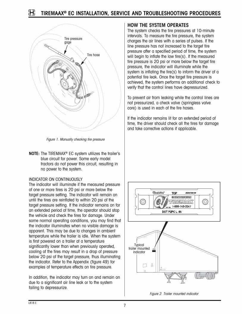
MANUALLY CHECKING TIRE PRESSURE
WARNING: TO PREVENT INJURY, ALWAYS WEAREYE PROTECTION WHEN MAINTAININGOR SERVICING THE VEHICLE.
NOTE: Check valves in the tire hoses help prevent tirepressure loss when a tire hose is removed.You may, however, experience air flow at theopen line and a low tire indication on theindicator, if the tire hose is disconnected andthe system is powered and attempts to checktire pressures.
To manually check tire pressure (figure 1):• Turn vehicle off
• Disconnect tire hose from tee at hubcap (or fromelbow at hubcap if super single configuration)
• Use a conventional gauge to measure tire pressureat hose end
• Reattach and firmly hand-tighten tire hose. Usingpliers, carefully and gently verify that the hose connection is tight
CAUTION: Do not overtighten tire hose or theinternal tire hose seal may bedamaged. Ensure tire hoses are notstretched or rubbing on the wheel.
INDICATOR DESCRIPTIONTWO BLINKS AT POWER-UPWhen +12 VDC power is applied, the indicator (figure 2) will blink two times (one second on, onesecond off, one second on, then off) as a systemverification and indicator bulb check. If the indicatordoes not blink two times at power-up, the indicatorbulb may be burned out or the system may not befunctioning. Verify proper power is applied to the system.
TIREMAAX® EC INSTALLATION, SERVICE AND TROUBLESHOOTING PROCEDURES
7L818 E
NOTE: The TIREMAAX® EC system utilizes the trailer’sblue circuit for power. Some early modeltractors do not power this circuit, resulting inno power to the system.
INDICATOR ON CONTINUOUSLYThe indicator will illuminate if the measured pressureof one or more tires is 20 psi or more below the target pressure setting. The indicator will remain onuntil the tires are reinflated to within 20 psi of the target pressure setting. If the indicator remains on foran extended period of time, the operator should stopthe vehicle and check the tires for damage. Undersome normal operating conditions, you may find thatthe indicator illuminates when no visible damage isapparent. This may be due to changes in ambienttemperature while the trailer is idle. When the systemis first powered on a trailer at a temperature significantly lower than when previously operated,cooling of the tires may result in a drop of pressurebelow 20 psi of the target pressure, thus illuminatingthe indicator. Refer to the Appendix (figure 49) forexamples of temperature effects on tire pressure.
In addition, the indicator may turn on and remain ondue to a significant air line leak or to the system failing to depressurize.
HOW THE SYSTEM OPERATESThe system checks the tire pressures at 10-minuteintervals. To measure the tire pressure, the systemcharges the air lines with a series of pulses. If theline pressure has not increased to the target tire pressure after a specified period of time, the systemwill begin to inflate the low tire(s). If the measuredtire pressure is 20 psi or more below the target tirepressure, the indicator will illuminate while the system is inflating the tire(s) to inform the driver of apotential tire leak. Once the target tire pressure isachieved, the system performs an additional check toverify that the control lines have depressurized.
To prevent air from leaking while the control lines arenot pressurized, a check valve (springless valvecore) is used in each of the tire hoses.
If the indicator remains lit for an extended period oftime, the driver should check all the tires for damageand take corrective actions if applicable.
Figure 1. Manually checking tire pressure
Tire hose
Tire pressuregage
Typicaltrailer mounted
indicator
Figure 2. Trailer mounted indicator

TIREMAAX® EC INSTALLATION, SERVICE AND TROUBLESHOOTING PROCEDURES
8L818 E
COMPONENTSCOMPONENT DESCRIPTIONRefer to figure 3 for major TIREMAAX® EC component illustrations. Refer to figures 18 through 22 for acomplete description of air fittings and hoses.
TIRE HOSE (WITH INTEGRAL CHECK VALVE)• Provides an air passage from the hubcap tee to the
tire
• Integral check valves in the tire hoses allow the airlines and seals to remain non-pressurized whenthe system is not checking or inflating the tires
• No modification to the standard valve stem or coreis required
• Allows for manual pressure check and fill at thehose end
ROTARY JOINT• Provides a means to allow the air to flow from a
non-rotating axle spindle to the rotating hubcap
• Composed of seals and bearings — the seal prevents air leakage from the rotating shaft
• Spindle plug provides a secure surface to mountthe rotary union and provides an air pressure ventin the hubcap during normal use and in the eventof rotary joint damage
• Under normal operation, the rotary joint will benon-pressurized for the majority of the time
CONTROLLER ASSEMBLY WITH ELECTRONICCONTROL UNIT (ECU)• Mounting bracket
• Solenoid valves- control the flow of air to the tires- separate supply side (air IN) and delivery side
(air OUT) ports, see figure 3- supply pressure solenoid valve has a serviceable
inlet filter to reduce contamination from the air source
• Pressure sensors- read tire pressure- read supply pressure (serves as a redundant
function check to verify sensor operation)
ELECTRONIC CONTROL UNIT• Uses input from pressure sensors to control the
solenoid valves, thus maintaining tire pressure
• Performs an indicator check to inform the driverthat the system is powered and operational
• Turns on the indicator when the measured tire pressure drops more than 20 psi below the targetpressure
• Detects faults and displays service codes via theLED on the controller assembly
• Provides diagnostic support via blink codes
• Allows the target tire pressure to be reprogrammedusing an optional, hand-held programming device

TIREMAAX® EC INSTALLATION, SERVICE AND TROUBLESHOOTING PROCEDURES
9L818 E
Figure 3. TIREMAAX® EC components
Indicator
Main power harness (J560 interface)
Controller assembly Hubcap and hose assembly
Hose assembly
Checkvalve
Tee fitting
Alternate style teeguard, used onHUS® hubs withbolt-on hubcaps
Rotary joint
Checkvalve
Hoseassembly
NOTE: Refer tofigures 18through 22 fordescriptions ofair fittings andhoses.
Tee fitting guard(not a step)
Mountingbracket
ECU
Pressuresensor
Pressuresensor
SolenoidsSupply side(air IN)
Delivery side(air OUT)
NOTE: Tire hoses mustbe connecteddirectly to the tirevalve stems andthe tee fitting. Donot use valvestem extenders.
Tire hoses, with wheel guards in place on hoseassemblies. Wheel guards help prevent the braidedsteel hoses from abrading the wheel.

INSTALLATIONINSTALLATION MATERIALS AND SUPPLIESIn addition to the hardware provided, the installershall provide the following:
• Hubcap* (unless pre-installed on dressed axle)
• Spindle plug driver and handle* (figure 9), unless the spindle plugs are already installed in theaxle from the factory
• Air lines and fittings (figures 18-22)
• Indicator and wire (figure 17)
• Optional hand-held programming device* to set target tire pressure (if a target tire pressure otherthan the preset value is desired) (figure 31)
• Controller assembly mounting bolts (figure 16)
• Pressure protection valve
• A regulated air supply at or below the target tirepressure (to pressurize the system for leak checks)
• An air chuck with a ¼-inch push-to-connect fitting(conveniently attaches to the exhaust tube on thecontroller, used to pressurize the system for leakchecks)
*Components unique to TIREMAAX® EC, available only from Hendrickson
INSTALLATION INTRODUCTIONIdentify the bullet item below that describes the condition of your trailer axles and proceed as directed.
• If the TIREMAAX EC system hardware is alreadyinstalled on a dressed axle, skip to the sectiontitled Controller Assembly Installation on page 22.
• If the TIREMAAX EC system axle hose and spindleplugs are already installed on the axle, skip to thesection titled Rotary Joint Installation on page 18.
• If the axles have been pre-drilled but no hardwarehas been installed, skip to the section titledComponent Installation on page 14.
• For retrofit installations, start with the proceduresdescribed below.
AXLE PREPARATIONThe following describes the procedure for preparing aHendrickson trailer axle (figure 4) for TIREMAAX EC system installation.
NOTE: The TIREMAAX EC system is not compatiblewith the castle (cotter pin-locked) spindle nutsystem. Use only the standard three-piece
TIREMAAX® EC INSTALLATION, SERVICE AND TROUBLESHOOTING PROCEDURES
10L818 E
spindle nut system (HN or HP spindles) or theHUS® spindle locking hardware (HUSspindles) with the TIREMAAX EC system.The PRO-TORQ spindle nut system may beused, but it may also require a Hendricksonhubcap spacer kit to provide the necessaryclearance between it and the rotary jointassembly.
WARNING: BLOCK ALL WHEELS BEFOREBEGINNING THIS INSTALLATIONPROCEDURE. NEVER WORK UNDERA VEHICLE SUPPORTED ONLY BY AJACK.
Figure 4. Axle spindle identification
HN spindle
HP spindle
HUS® spindle
Figure 5. Trailer preparation

TIREMAAX® EC INSTALLATION, SERVICE AND TROUBLESHOOTING PROCEDURES
11L818 E
1. Block the tires to keep the trailer from moving(figure 5).
2. Exhaust the trailer air system.
3. If the wheel end is oil lubricated, drain the oilfrom the hubcap and discard the oil.
4. Remove the hubcap bolts and hubcap.
5. Remove the spindle plug from the spindle.
6. Remove the in-axle filter.
7. Inspect the spindle plug bore and remove anyburrs or sealant.
8. Check the inside of the spindle to ensure thatthere is a passage through the axle to allowinstallation of the air line.
9. For all INTRAAX® and VANTRAAX® suspensions -locate the three ¼-inch pipe plugs in the axlewrap windows, remove the plugs and proceed tothe Component Installation section on page 14.If the axle does not have pre-drilled holes in theaxle wrap windows, proceed to step 10 for holedrilling details.
For Hendrickson Trailer Axles - locate the three¼-inch pipe plugs in the middle of the axle,remove the plugs, and proceed to theComponent Installation section on page 14. If
Figure 6. INTRAAX / VANTRAAX suspension axle drilling details
3 × 7/16-inch drill through oneside tap ¼-inch-18 NPTF-1thread per ANSI B1.20.3
IMPORTANT: The edge ofany hole mustbe a minimumof ½ inchaway from theedge of thefillet weld thatsurrounds thewrap window.
NOTE: One wrap windowwill have two holes(the second holeaccommodates anaxle ventassembly). Theseholes must bewithin the approveddrilling area butspaced far enoughapart to allow 90-degree elbowfittings to bethreaded into them.Approved
drilling area½ inch minimumDO NOT drill
Axle wrap

the axle does not have three pre-drilled holes inthe middle of the axle, proceed to step 10 forhole drilling details.
10. Using the information in figure 6 or 6a, drill andtap three ¼-inch - 18 NPT holes in the axlewrap windows (on INTRAAX and VANTRAAX suspensions) or at the midpoint of the axle (onHendrickson Trailer Axles) to prepare for component installation.
NOTE: In most cases, it will be necessary to removethe slack adjuster and camshaft to gainaccess to the approved drilling area. Refer toHendrickson publication L496, Wheel-EndMaintenance Procedures (available atwww.hendrickson-intl.com), for completeslack adjuster and camshaft removal instructions.
NOTE: Remove the debris generated by the drillingand tapping operations from inside the axlebefore proceeding with the next step.
11. Proceed to the COMPONENT INSTALLATIONsection on page 14.
TIREMAAX® EC INSTALLATION, SERVICE AND TROUBLESHOOTING PROCEDURES
12L818 E
Drill three 7/16-inchholes through oneaxle wall at axletop dead center.Tap ¼-inch-18NPTF-1 thread perANSI B1.20.3
Midpoint of axle (equidistantfrom each spindle end)
11.5"* 11.5"*
Figure 6a. Hendrickson Trailer Axle drilling details
Center hole is usedfor axle ventinstallation
*Before drilling, make sure holeswill not interfere with suspensionmounting method. If holes willinterfere, contact Hendricksontechnical service at 866-743-3247 in the United States or800-668-5360 in Canada.

TIREMAAX® EC INSTALLATION, SERVICE AND TROUBLESHOOTING PROCEDURES
13L818 E

TIREMAAX® EC INSTALLATION, SERVICE AND TROUBLESHOOTING PROCEDURES
14L818 E
COMPONENT INSTALLATIONRefer to the following assembly procedures to complete the installation of the TIREMAAX® EC tire inflation system. Component installation proceduresinclude:• Axle hose installation
• Spindle plug installation
• Hub installation requirements
• Hendrickson hubcap spacer kit installation
• Rotary joint installation
• Hubcap assembly
• Controller assembly installation
• Wiring harness installation
• Axle vent and control line installation
• Tire hose installation
AXLE HOSE INSTALLATION1. On the end of the axle tube with two ¼-inch
holes in the wrap window (on INTRAAX andVANTRAAX suspensions), route the small end ofthe metal braided hose into the hole closest tothe spindle end (figure 7). On HendricksonTrailer Axles, route the small end of the metalbraided hose into the hole closest to the spindle.
2. Making sure that the hose heads toward thespindle end, continue feeding the metal braidedhose into the axle tube until the small end of thehose exits the spindle end.
Figure 7. Routing hose in axle
Route braidedhose into axle
NOTE: Tapered (HN)spindle shown, butprocedure is thesame for HP andHUS® spindles.

TIREMAAX® EC INSTALLATION, SERVICE AND TROUBLESHOOTING PROCEDURES
15L818 E
3. Thread the large adapter end of the axle hoseassembly into the axle and tighten to 20 ft. lbs.(27.1 N•m) of torque (figure 8).
4. If not already present, cut an inch-wide slit in thecenter of the axle filter and feed the metal braidedhose through the slit in the filter. Push the axlefilter into the spindle cavity (figure 8).
5. Remove the protective coverings from the end ofthe axle hose assembly and blow air through thehose assembly to remove any debris.
6. Repeat steps one through five on the other end ofthe axle. Leave the axle vent hole (figure 8)vacant for now. This hole will be used toaccommodate the axle vent in a later installation.
Figure 8. Installed position of hose assembly
Thread adapterinto axle, tightento 20 ft. lbs.(27.1 N•m) oftorque
NOTE: Tapered (HN)spindle shown, butprocedure is thesame for HP andHUS® spindles.
Filter
Axle vent hole

TIREMAAX® EC INSTALLATION, SERVICE AND TROUBLESHOOTING PROCEDURES
16L818 E
SPINDLE PLUG INSTALLATION1. On one end of the axle, route the end of the
braided hose through the center of the spindleplug (figure 9).
2. With the spindle plug breather hole orientedtoward the pivot bushing (figure 9), place theplug assembly against the spindle end.
3. Route the braided hose into the center of the plugdriver and press the plug into the spindle enduntil the driver bottoms on the end of the spindle.
NOTE: The driver regulates the correct installationdepth. Refer to Hendrickson publication B113,TIREMAAX® EC Spindle Plug Installation Depth(available from www.hendrickson-intl.com) forcomplete installation details.
4. Repeat steps one through three on the other endof the axle.
HUB INSTALLATION REQUIREMENTSWARNING: A minimum hub bore depth is
required when installing theTIREMAAX EC system (figure 10).This hub requirement helps keep theproper clearance between the rotaryjoint assembly and the spindle nutsystem (figure 10), thus preventingcontact or interference betweenthese parts which could result inwheel-end failure and severepersonal injury or death.
Any hub may be used with the TIREMAAX EC system,provided a minimum hub bore depth requirement(dimension “A” in figure 11) is maintained.
If the hub bore dimension is greater than or equal tothe dimension shown in the chart in figure 11, youmay use the hub “as is” with the TIREMAAX EC system.
Plug driverhandle
Spindle plug with breather holeoriented toward pivot bushing
Plug driver
Braided hose
Figure 9. Spindle plug installation
NOTE: Tapered (HN) spindleshown, but procedureis the same for HPand HUS® spindles.
Filter
1 2
Item Name Part Number “A” Dimension Spindle Type
1 Plug driver S-28146-1 1.75 inches HN
1 Plug driver S-28146-2 2.50* inches HP*
1 Plug driver S-28146-3 2.75* inches HP* & HUS
2 Plug driver handle S-27399 — —
Plug Driver and Handle Assembly Ordering Information
“A”
* Before March 28, 2003, Hendrickson manufactured HP spindles with both 2.5" and 2.75" inner borediameters. After this date, the HP spindle bore was standardized at 2.75".
Orient spindle plugbreather hole towardpivot bushing

TIREMAAX® EC INSTALLATION, SERVICE AND TROUBLESHOOTING PROCEDURES
17L818 E
Figure 10. TIREMAAX® EC hub requirement
Hub
Rotary jointassembly
Spindle nutsystem (typical)
a. b.
Minimumhub boredepth
Figure 11. Minimum hub bore depth
HN spindle
HP spindle
Dimension “A” is the minimum hub bore depthrequired to install the TIREMAAX EC system and ismeasured from the bottom of the bearing cup tothe hubcap mounting surface.

TIREMAAX® EC INSTALLATION, SERVICE AND TROUBLESHOOTING PROCEDURES
18L818 E
ROTARY JOINT INSTALLATIONNOTE: The hubs and drums should be installed
before installing the rotary joint assemblies.
There are two styles of rotary joint assembly (figure12a): one with a threaded axle hose connector (current production) and one with a barbed axle hoseconnector (earlier style). Use the procedure belowthat matches your rotary joint and axle hose hardware.
Figure 12. Hubcap spacer kit installation
Hub cap
Gasket
Spacer
Gasket
If the hub bore dimension is less than the dimensionshown in the chart in figure 11, you may still use thehub with the TIREMAAX EC system, but aHendrickson hubcap spacer kit is required.
Hendrickson offers hubcap spacer kits for HN and HPspindles to accommodate most hubs without therequired bore dimension. Each kit consists of 3/8-inchspacers, gaskets, hubcap bolts and lock washers inquantities to adapt one axle. The hubcap spacer kitpart numbers are:
HENDRICKSON HUBCAP SPACER KITINSTALLATIONIf the hub you intend to use does not meet the minimum hub bore depth requirement, use the following procedure to install the hubcap spacer kit.
1. Sandwich the spacer between two gaskets asshown in figure 12.
2. Install the hubcap using the bolts and lockwashers provided in the kit. Tighten the hubcapbolts to 12-18 ft. lbs. (16-24 N•m) of torque.
HN
HP
S-28040
S-28093
SPINDLE TYPE HUBCAP SPACER KIT PART NUMBER
Threadedaxle hoseconnector
Barbedaxle hoseconnector
Threaded axle hose
Plain axle hose
Hose end adapter
Figure 12a. Rotary union / axle hose connections
Clamp
Current production Earlier style

4. Using the rotary union spanner wrench (figure13a), screw the threaded rotary union into thethreaded axle hose (or hose-end adapter) andtighten to 30 in. lbs. (3.4 N•m) of torque.
TIREMAAX® EC INSTALLATION, SERVICE AND TROUBLESHOOTING PROCEDURES
19L818 E
If your axle hose is threaded, you will not need toinstall the hose-end adapter (figure 12a). Continuewith step 4.
If your axle hose has a plain end, you will need toinstall the hose-end adapter as follows:
1. On one end of the axle, place the hose clamponto the braided axle hose sticking out of thespindle plug (figure 13).
2. Slide the barbed end of the hose-end adaptercompletely into the end of the braided hoseassembly until the hose bottoms on the adapter.There must not be any gap between the hoseand the hose-end adapter (figure 13).
3. Position the clamp over the barbed end of thehose-end adapter. Leave a 1/8- to 1/16-inch spacebetween the clamp and the hose-end adapter asshown in figure 13. Using a crimping tool(Oetiker® pliers), squeeze the clamp to tightenthe hose to the hose-end adapter. The clampinner surfaces must touch for a proper seal(figure 13). Continue with step 4.
Figure 13. Rotary joint installation
Crimping tool
Beforecrimping After
crimping
Rotary jointassembly
Leave 1/8- to 1/16-inch space betweenhose clamp and hose-end adapter
Spindle
hose clampT20 Torxfasteners
Hose-endadapter
No gap betweenhose and hose-endadapter
Hose clamp
Rotary union spanner wrench(available in kit S-29430)
Figure 13a. Rotary union spanner wrench use
Tighten threaded axlehose (or hose-endadapter) to 30 in. lbs.(3.4 N•m) of torque
Common 3/8" drivetorque wrench withcrows foot attachment
Axle hose
Prongs
Rotary unionmounting holes

TIREMAAX® EC INSTALLATION, SERVICE AND TROUBLESHOOTING PROCEDURES
20L818 E
NOTE: The rotary union spanner wrench serves twopurposes. It offers a convenient way to holdthe rotary union stationary while the threadedaxle hose connection is tightened. And sincethe rotary union is manufactured in twohalves, the prongs keep both halves of therotary union from rotating while the axle hoseconnection is being made, thereby ensuringthat the mounting holes in both halves of therotary union stay aligned.
5. Push the rotary union / axle hose assembly intothe spindle plug, aligning the holes in the rotaryunion with the threaded holes in the spindleplug.
IMPORTANT: To align the holes, rotate the rotaryunion / axle hose assembly CLOCKWISEONLY. This ensures that the torquedconnection will not loosen.
6. Insert the three T20 Torx fasteners into the rotaryjoint assembly and fasten to the spindle plug(figure 13). Tighten the fasteners to 45 ±5 in.lbs. (5 ±½ N•m) of torque.
7. Rotate the rotary joint assembly one full turn.Make sure that the steel air tube does not contactany part of the spindle or spindle nut system.
8. Repeat steps one through five on the other sideof the axle.
Figure 14. Completed installation of rotary joint assembly
Spindle
HUBCAP ASSEMBLY1. Place a hubcap gasket over the rotary joint exit
tube and bulkhead adapter.
2. Lubricate the O-ring on the rotary joint bulkheadadapter. Use the same lubricant as is used in thehub or a light film of #2 grease, white lithiumgrease or Vaseline®.
3. From the inside, insert the bulkhead adapterthrough the hole in the hubcap labeled “Air”.
4. Align the flat on the bulkhead adapter with the anti-rotation flat in the hubcap (figure 15).
Note the orientation indicator on the top of thebulkhead adapter threads (figure 15, view a).Use this indicator (some models have a dot,other models have a notch) to properly orient thebulkhead adapter in the hubcap hole. When theflat on the bulkhead adapter is properly alignedwith the anti-rotation flat in the hubcap, theorientation indicator will face outboard (figure 15,view b).
WARNING: Failure to properly align the flats asdescribed above will result in wheel-end contamination and could lead towheel-end failure.
Do not use pliers or any kind of wrench to pullthe bulkhead adapter up through the hole in thehubcap. This could cause the bulkhead adapterto rotate before it engages the flat in thehubcap, potentially damaging the rotary unionor hubcap.
Attach the jam nut and hand tighten. Whenproperly seated, the top of the bulkhead adapterwill be flush (or higher) with the top of the jamnut when hand tightened (figure 15, view c).
NOTE: If wheels are installed, refer to figure 23 todetermine the correct “clocking” of the hubcap.The wheel must be properly “clocked” to thehubcap to prevent the hoses from rubbing onthe wheel. Failure to properly “clock” thewheels may result in hose failure.
5. Install the hubcap. If the hubcap is a screw-onstyle used on the HUS hub, tighten it to 50-100ft. lbs. (68-137 N•m) of torque. If the hubcap is

TIREMAAX® EC INSTALLATION, SERVICE AND TROUBLESHOOTING PROCEDURES
21L818 E
Figure 15. Hubcap to bulkhead adapter connection details
Rotary joint bulkhead adapter
Nut
Hubcap
Rotary joint exit tubeSpindle
Anti-rotation flatFlat onbulkheadadapter
Hubcap
Orientation indicator(could be a dotor a notch)
Indicatorlines upwith flat,provides a visualreferencewhenbulkheadadapter isinserted intohubcap.
Flat When bulkhead adapter is properlyinserted in hubcap, indicator facesoutboard (away from hubcap).
When properly seated, bulkheadadapter is flush with top of jam nutwhen jam nut is hand tightened.
Bulkhead adapter Jam nut
a. b. c.
a bolt-on style used on the other hubs, tightenthe hubcap bolts to 12-18 ft. lbs. (16-24 N•m)of torque.
6. Tighten the rotary joint jam nut to 15 ft. lbs. (20 N•m) of torque.
7. For oil filled hubs, install lubricant in the wheelend to the correct level.

TIREMAAX® EC INSTALLATION, SERVICE AND TROUBLESHOOTING PROCEDURES
22L818 E
Figure 16. Controller assembly installation
Cross member
Install controller sosolenoid vent tubepoints downward
3/8-inchmounting bolts
Hendrickson K-2slider box
Side view
3/8-inchmounting bolts
Cross member
2¼inches
7/16-inchholes
Front of trailer
CONTROLLER ASSEMBLY INSTALLATIONOn Hendrickson K-2® slider box suspensions, mounting holes for the controller assembly are provided on the forward cross member (figure 16).On other suspensions without mounting holes, alocation must be selected and holes drilled to mountthe controller assembly.
1. Pick a mounting location for the controllerassembly so that it can be convenientlyconnected to the trailer air tank. Rigidly mount(no rubber insulator) the controller in a locationthat is accessible and free of hazards. Forexample, inboard of the trailer frame rails andaway from the tires.
2. Drill two holes on 2¼-inch centers toaccommodate the mounting bracket. Attach thecontroller assembly with two 3/8-inch fasteners(figure 16). Orient the controller so that it isprotected within the cross member and the ECUpoints rearward (figure 16).
CAUTION: The controller assembly must bemounted vertically with the solenoidvent tube pointing down (figure 16).This properly orients the exhaust portto prevent damage.
CAUTION: Do not weld on the controllerassembly mounting bracket withoutfirst removing the ECU and solenoidvalves from the bracket. Refer to theService Procedures sectionbeginning on page 46 for ECU andsolenoid valve removal instructions.
CAUTION: Cover controller assembly prior topainting or undercoating the trailer toprevent plugging of pressure sensorsand ECU ports.
WIRING HARNESS INSTALLATIONTIREMAAX® EC comes standard with a three-wire, 18-inch long harness (figure 17). The red wire of thisharness is the indicator power lead, it connects to thetrailer-mounted indicator. The white wire must beconnected to vehicle ground and the blue wire mustbe connected to 12 VDC vehicle power. The

TIREMAAX® EC INSTALLATION, SERVICE AND TROUBLESHOOTING PROCEDURES
23L818 E
Figure 17. Trailer wiring harness installation
J560 interface
Trailer-mountedIndicator
These componentsprovided by trailermanufacturer (notincluded withTIREMAAX® EC)
Five-pin Packard
To ECU
ToABS
Standardharness
Premium, ABS-ready harness
Red (indicatorpower)
White (ground)
Blue (12 VDCpower)
Indicator power lead
Use an internalground or run adedicatedground wire fromthe indicator tothe plug thatconnects thetrailer to the towvehicle.
termination of these wires is the responsibility of theinstaller. Terminals and connectors must be weather-proof, and corrosion prevention compound must beused on all connectors. Refer to TMC RP 113, 114,and 704 for recommended wiring practices.
A premium, 15-foot long ABS-ready harness is anavailable option. It plugs into the five-pin Packardconnector coming from the J560 interface and provides a pass-through ABS connection. To installthe TIREMAAX® EC wiring harness:
1. Standard harness - Connect the blue wire tovehicle power and the white wire to vehicleground.
ABS harness - Plug the five-pin male Packardconnector into the mating connector coming fromthe J560 interface.
2. Connect the other end of the harness to the ECU.
3. Mount the indicator on the front corner or side ofthe trailer within view of the operators side viewmirror. On tractor applications with large windfairings, locating the indicator near the left rearwheels (near the ABS warning lamp) may bepreferable. Connect one side of the indicator toground (an internal ground, or a dedicatedground wire from the indicator to the plug thatconnects the trailer to the tow vehicle isrecommended).
4. Route the indicator power wire (16 AWGminimum) and connect it to the red wire on theTIREMAAX EC harness.
5. Secure harness and wires as required.
Alternate stylepremium, ABS-readyharness

TIREMAAX® EC INSTALLATION, SERVICE AND TROUBLESHOOTING PROCEDURES
24L818 E
Figure 18. Typical axle vent installation
90 degree, ¼-inchNPT to 3/8-inch nylontubing adapter
3/8-inch outsidediameter coiledair brake tubing
Duck bill check valve(end must point down)
Duck bill check valve(end must point down)
Suspension beam
Axle wrap
Axle
AXLE VENT INSTALLATION1. Install a 90 degree, ¼-inch NPT male to 3/8-inch
nylon tubing adapter in the remaining ¼-inchthreaded hole in the axle tube (figure 18).
2. Loop the 3/8-inch outside diameter coiled tubingaround the axle. On INTRAAX / VANTRAAXsuspensions, loop the coiled tubing around theaxle inside the suspension beam as shown infigure 18. If not already installed, attach the duckbill check valve to the tubing making sure theend points down to prevent contamination (figure18). To attach the duck bill check valve, slidethe duck bill check valve onto the tubing andsecure with the provided clamp. Do not use glueor any other substance that could plug the duckbill valve.
CAUTION: To prevent contamination of theaxle, ensure the adapters and theduck bill check valve are securelyfastened and the duck bill checkvalve-end points down.
WARNING: Failure to properly install axle ventmay result in wheel-endpressurization and/or water ingestion,which could cause wheel-end failureand severe personal injury or death.
CONTROL LINE INSTALLATIONProper TIREMAAX® EC operation requires correct airline diameters and lengths. The following diagrams (figures 19-22) show air brake tubing lengths andsizes and associated fittings required to complete thesystem installation. Control line routing recommendations are also included.
CAUTION: To prevent twisting the air line insidethe axle when tightening fittings tothe axle hose fitting, use a wrenchto hold the axle hose fitting.
CAUTION: Proper TIREMAAX EC operationrequires correct air line diametersand lengths. Installation sizes andlengths must be within limits shown.
CAUTION: Proper TIREMAAX EC operationrequires correct air line connections.All junctions of two or more ¼-inchlines must increase to 3/8-inch linefor adequate air flow.
CAUTION: To prevent TIREMAAX ECcontamination, do not install fittingson the bottom of the trailer air tank.
NOTE: INTRAAX / VANTRAAX suspension shown, butaxle vent installation procedure is the samefor Hendrickson Trailer Axles. On these axles,the vent tube is installed in the center hole(refer to figure 6a).

TIREMAAX® EC INSTALLATION, SERVICE AND TROUBLESHOOTING PROCEDURES
25L818 E
Loop hose around suspensionbeam as shown**
Figure 19a. Suggested control line installation details for Top Mount, Narrow Bushing, Standard Duty Models (HKANT, AANT, AAZNT)
Without SURELOK®
With SURELOK Route control line through hole insuspension beam or beam extension**
Route control line throughhole in beam extension
Grommet
Grommet
Route control line througheither hole in suspensionbeam*
** It is the OEMs responsibility to route air lines and orient axleconnector fittings so as to eliminate interference between slackadjusters and air lines.
*On top mount, wide bushing, standard duty models withoutSURELOK, it is permissible to route the control line througheither hole in the suspension beam. Just orient the axleconnector fitting to obtain the best slack adjuster / air lineclearance.
Figure 19. Suggested control line installation details for Top Mount, Wide Bushing, Standard Duty Models (AAT, HKAT)
ADDITIONAL AXLESFor systems with three or four axles, observe theinstallation requirements as shown in the followingdiagrams (figures 19-22). Extend the main 3/8-inchrun as necessary. However, all total line lengths muststill remain within the limits listed in the diagrams.

TIREMAAX® EC INSTALLATION, SERVICE AND TROUBLESHOOTING PROCEDURES
26L818 E
Figure 19c. Suggested control line installation details for Low Ride, Short Beam, Narrow Bushing, Standard Duty Models (AANLS 20K)
Route control line throughhole in suspension beam**
Route control line through holein suspension beam**
Figure 19b. Suggested control line installation details for Low Ride, Wide Bushing, Standard Duty (AAL 23K, AAL 25K, AAZL, AAL30K); Low Ride, Wide Bushing, Extreme Duty (AAEDL 30K); and Top Mount, Wide Bushing, Extreme Duty (AAEDT 30K) Models
Figure 19d. Suggested control line installation details for Low Ride, Narrow Bushing, Standard Duty Models (AANL)
Route control line throughhole in suspension beam**
** It is the OEMs responsibility to route air lines and orient axleconnector fittings so as to eliminate interference between slackadjusters and air lines.

TIREMAAX® EC INSTALLATION, SERVICE AND TROUBLESHOOTING PROCEDURES
27L818 E
C
C
B
B
H
H
A
B
C
D
E
F
G
H
I
D
E E
D
DE
I
EJ
I
J
C
J
G
F
A
K
LA
K
L
Front
Controllerassembly
Trailer air tank
Air line 3/8-inch OD nylon air brake tubing; any length
Item Description
Air line 3/8-inch OD nylon air brake tubing; up to 15 feet total system length
Air line ¼-inch OD nylon air brake tubing; 30 to 50 feet total system length
Axle connector 90-degree elbow, 1/8-inch NPT male to ¼-inch NTA
Axle hose fitting 1/8-inch NPT female
Controller IN fitting 1/8-inch NPT male to 3/8-inch NTA
Controller OUT fitting run tee: 1/8-inch NPT male, 3/8-inch NTA, 3/8-inch NTA
Tee assembly ¼-inch NPT union tee, two ¼-inch NTA fittings and one 3/8-inch NTA fitting (four total fittings)
Axle vent fitting 90-degree elbow, ¼-inch NPT male to 3/8-inch NTA
NTA = nylon tubing adapter
Figure 20. Typical TIREMAAX EC plumbing schematic — two axles with 3/8- and ¼-inch lines
Air line 3/8-inch OD nylon air brake tubing; one loop around axle with duck bill check valve on end
Pressure protection valve required; 70 psi minimum closing pressure; existing suspension valve can be used
PPV OUT fitting run tee: ¼-inch NPT male, 3/8-inch NTA, 3/8-inch NTA
To height control valve
= included with TIREMAAX® EC-prepped axles
NOTE: To maintain adequateairflow, all air lines cominginto and going out of thecontroller assembly must be3/8 inch, and all junctions oftwo or more ¼-inch linesmust be supplied by 3/8-inchline.

TIREMAAX® EC INSTALLATION, SERVICE AND TROUBLESHOOTING PROCEDURES
28L818 E
A
B
C
D
E
F
G
H
A
B
C
D
C
G
H
I
F
E
J
L
I
J
K
K
L
M
J
D
M
NA
N
Front
Controller assembly
Trailer air tank
Air line 3/8-inch OD nylon air brake tubing; any length
Item Description
Air line ¼-inch OD nylon air brake tubing; 10 to 25 feet total system length
Axle connector 1/8-inch NPT male to ¼-inch NTA
Axle hose fitting 90-degree elbow, 1/8-inch NPT female
Controller IN fitting 1/8-inch NPT male to 3/8-inch NTA
Reservoir OUT assembly run tee: 1/8-inch NPT male, ¼-inch NTA, ¼-inch NTA (three total fittings)
Axle vent fitting 90-degree elbow, ¼-inch NPT male to 3/8-inch NTA
NTA = nylon tubing adapter
Figure 21. Typical TIREMAAX EC plumbing schematic — single axle with ¼- and 3/8-inch lines
Air line 3/8-inch OD nylon air brake tubing; one loop around axle with duck bill check valve on end
Reservoir 10 to 20 cubic inch capacity; Hendrickson part number A-22357
Bushing ½-inch NPT male to 1/8-inch NPT
Fitting 1/8-inch NPT male to 3/8-inch NTA
Air line 3/8-inch OD nylon air brake tubing; two feet maximum length
Pressure protection valve required; 70 psi minimum closing pressure; existing suspension valve can be used
PPV OUT fitting run tee: ¼-inch NPT male, 3/8-inch NTA, 3/8-inch NTA
To height control valve
= included with TIREMAAX® EC-prepped axles
NOTE: To maintain adequateairflow, all air lines cominginto and going out of thecontroller assembly must be3/8 inch, and all junctions oftwo or more ¼-inch linesmust be supplied by 3/8-inchline.

TIREMAAX® EC INSTALLATION, SERVICE AND TROUBLESHOOTING PROCEDURES
29L818 E
C
A
B
C
D
E
F
G
H
I
J
K
OR
D
H
BE E
D
DE
I
EJ
I
J
F
B
GK
L
A
A
L
Front
ControllerassemblyTrailer air tank
Plug
To additional axles(four axles maximum per controller)
Air line 3/8-inch OD nylon air brake tubing; any length
Item Description
Air line 3/8-inch OD nylon air brake tubing; up to 15 feet total system length
Air line ¼-inch OD nylon air brake tubing; 30 to 50 feet total system length
Axle connector 90-degree elbow, 1/8-inch NPT male to ¼-inch NTA
Axle hose fitting 1/8-inch NPT female
Controller IN fitting 1/8-inch NPT male to 3/8-inch NTA
Controller OUT fitting 1/8-inch NPT male to 3/8-inch NTA
Junction manifold 3/8-inch NTA inlet, ¼-inch NTA outlets
Axle vent fitting 90-degree elbow, ¼-inch NPT male to 3/8-inch NTA
NTA = nylon tubing adapter
Figure 22. Typical TIREMAAX EC plumbing schematic — two axles with 3/8- and ¼-inch lines and junction manifold
Air line 3/8-inch OD nylon air brake tubing; one loop around axle with duck bill check valve on end
Pressure protection valve required; 70 psi minimum closing pressure; existing suspension valve can be used
PPV OUT fitting run tee; ¼-inch NPT male, 3/8-inch NTA, 3/8-inch NTA
To height control valve
= included with TIREMAAX® EC-prepped axles
NOTE: To maintain adequateairflow, all air lines cominginto and going out of thecontroller assembly must be3/8 inch, and all junctions oftwo or more ¼-inch linesmust be supplied by 3/8-inchline.

1. Position the hubcap and wheel so the hoseswill not stretch or rub on the wheel. Refer tofigure 23.
CAUTION: The wheel must be properly“clocked” to the hubcap to preventthe hoses from rubbing on the wheel(figure 23). Failure to do so mayresult in hose failure.
NOTE: All air lines coming into and going out of thecontroller assembly must be 3/8 inch, and alljunctions of two or more ¼-inch lines mustincrease to 3/8-inch line to maintain adequateair flow.
TIRE HOSE INSTALLATIONNOTE: Tire hoses must be connected directly to the
tire valve stems and the tee fitting. Do not usevalve stem extenders.
TIREMAAX® EC INSTALLATION, SERVICE AND TROUBLESHOOTING PROCEDURES
30L818 E
Figure 23. Properly clocking the wheels to prevent the hoses from rubbing
Dual wheelconfiguration
clock “A”
For 17.5- or 22.5-inch, five-hole or five-spoked wheels
For 19.5- or 24.5-inch, five-hole or five-spoked wheels
For any size, two-hole or four / six-spoked wheels
7 to 8 o’clock
With the bulkhead adapter in the 12 o'clock position, the valvestem should be located between 7 and 8 o'clock for most appli-cations. When the wheel is installed, verify that the tire hose isnot stretched so tightly that a strain is introduced at either thevalve stem or hubcap fitting. Also make sure the tire hose is notso loose that it contacts the wheel.
This illustration shows the valve stem pointing outboard (towardthe viewer). Other valve stem orientations could be supplied bythe wheel manufacturer. Do not rotate or otherwise alter the orientation of the valve stem as supplied from the wheel manu-facturer. Valve stem orientation is not critical to TIREMAAX performance as long as the hose is routed as noted above.
Check to ensure that no portion of the tire hose extends furtheroutboard than the outer face of the wheel. If this occurs, contactHendrickson for instructions on how to route the hoses to avoidthis.
Dual wheelconfiguration
clock “C”
Dual wheelconfiguration
clock “B”
Super singlewheel
configuration
NOTE: For dual wheel configurations, proper clocking isparticularly important since two wheels (inner and outer)must be properly oriented for proper installation.

One way to approximate 130 ±10 in. lbs. oftorque is to tighten the tee fitting swivel threadshand tight and then use the two-wrench methodas described previously to tighten the swivelthreads one additional turn. Hendricksonrecommends tightening to the stated torquevalue, but if you use the approximate method,make sure the tee fitting cannot be rotated freelywithin the bulkhead fitting after the additional onefull turn.
3. Attach the tire hose(s) to the tire valve stem(s)and tighten finger tight (figure 24a).
2. Screw the tee fitting onto the rotary joint bulkheadadapter (figure 23a) and tighten the swivelthreads to 130 ±10 in.lbs. of torque. Use twowrenches to achieve the final torque value. Useone wrench to hold the jam nut on the rotaryjoint bulkhead adapter stationary and use thesecond wrench to tighten the tee fitting swivelthreads to the final torque value.
TIREMAAX® EC INSTALLATION, SERVICE AND TROUBLESHOOTING PROCEDURES
31L818 E
Tee fitting
Rotary joint bulkhead adapter(use one wrench to hold thejam nut stationary whiletightening the tee fitting swivelthreads with a second wrench)
Jam nut
Figure 23a. Tee installation
NOTE: A dual wheel tee fitting is shown in the illustration above,but the installation is the same for elbow-style tee fittingsused on super single wheel configurations.
Figure 24. Tire hose, check valve and tee fitting guard installation
Elbowfitting
Checkvalve
Tee fitting guards (not to be used as a step)Tee fitting guards (not to be used as a step)
Inner-wheel hoseassembly
Outer-wheel hoseassembly
Check valve Check valve
Tee fitting
Dual wheel configuration Super single configuration
NOTE: Tire hoses must beconnected directly tothe tire valve stemsand the tee fitting.Do not use valvestem extenders.
NOTE: Tire hose must beconnected directly tothe tire valve stemand the tee fitting.Do not use a valvestem extender.
Tire hose
Tirevalvestem
Tirevalvestem
Tire hose
Tighten finger tight... then use a wrench to tighten an additional one-half turn
Figure 24a. Attaching the tire hose to the tire valve stem
Alternate style tee guard, used onHUS® hubs with bolt-on hubcaps
Alternate styletee guard, usedon HUS® hubswith bolt-onhubcaps

After assembly is complete, the tire hose /valve stem connection (and all other air systemconnections) will be checked for leaks usingthe system integrity check found on page 33.
NOTE: Simply spraying the connections to look forleaks will not work. Use a commerciallyavailable leak detector solution and the systemintegrity check to verify airtight connections.
6. Attach the tee fitting guard. Remove the two hubcap bolts closest to the rotary joint bulkheadadapter, place the tee fitting guard over the rotaryjoint bulkhead adapter and reinstall the hub capbolts through the holes in the tee fitting guard.Tighten to 12 - 18 ft. lbs. (16 - 24 N•m) oftorque.
NOTE: Tire hoses must be connected directly to thetire valve stems and the tee fitting. Do not usevalve stem extenders.
4. Using a 7/16-inch wrench, tighten the tire hose /valve stem connection an additional one-halfturn (figure 24a). Do not overtighten thisconnection. The hose and tee connections aretight enough when moving the hose back andforth does not cause the connection to move.
CAUTION: DO NOT overtighten the tire hose(s)on the tire valve stem(s). Doing somay damage the tire hose internalgasket, causing a leak or decreasedsystem performance. Only tightenthe connection an additional one-half turn with the wrench.
5. Attach tire hose and check valve assemblies tothe tee or elbow fitting and tighten finger tight(figure 24). Using pliers, carefully and gentlyverify that the hose connection is tight.
CAUTION: DO NOT overtighten the knurled tirehose nut. Doing so will bend the tee/ elbow fitting stem and compromisethe integrity of internal tee / elbowfitting components. Do not damageknurled finish on tire hose nut. Doingso will make tire hose removalextremely difficult.
Recheck the tire hose connections at the valvestems. Verify that the tire hose / valve stemconnection did not loosen during the tire hose /tee fitting connection process.
TIREMAAX® EC INSTALLATION, SERVICE AND TROUBLESHOOTING PROCEDURES
32L818 E
Figure 25. Recommended controller assembly mounting location and label placement
Controller assemblyIndicator status decalL861
Figure 25a. Recommended decal mounting location

TIREMAAX® EC INSTALLATION, SERVICE AND TROUBLESHOOTING PROCEDURES
33L818 E
Figure 26. Manually pressurizing the systemto check for air leaks
Vent tube(¼-inch nylon tubing)
Air chuck with a ¼-inchpush-to-connect fitting(installed on vent tube)
Regulated shop air supply (not to exceed target pressure)
Air chuck with a ¼-inchpush-to-connect fitting
CAUTION: Potential overinflation hazard. Whenperforming the system integritycheck, the shop air supply MUSTNOT be higher than the targetpressure setting.
If the shop air supply is higher, thetires will overinflate during thesystem integrity check. No methodexists to exhaust the overinflatedtires, other than disconnecting thetire hoses and manually depressingthe valve stem core at each tire.
To vent tubeTo shop airsupply
Pressure regulator apparatus VS-28707
NOTE: The tee fitting guard is not used on HUS® hubswith screw-on hubcaps.
LABEL LOCATION1. Install indicator status decal L861 at the front of
the trailer near the indicator (figure 25).
2. If decal L918 is included in the literature packet,install it on the hubcap as shown in figure 25a.
SYSTEM INTEGRITY CHECKAfter the installation is complete but before the traileris put into service, all air system connections mustbe checked for leaks. This is done by manually pressurizing the system from a shop air supply andapplying soapy water to all air connections. A hissingsound or bubbles in the soapy water will provideaudio and visual indications of air leaks.
The TIREMAAX® EC system can be manually pressurized without applying electrical power. An airchuck with a ¼-inch push-to-connect fitting can beattached to the vent tube on the delivery solenoidvalve, conveniently allowing shop air to pressurizethe system. Hendrickson offers a regulator apparatusspecifically for this purpose (part number VS-28707,figure 26). The push-to-connect fitting also has theadded benefit of being easy to install and removefrom the vent tube. Manually pressurize the TIREMAAXEC system as follows:
1. Fill the trailer air system and set all tire pressuresas close to target pressure as possible. Withelectrical power disconnected, manually measurepressure at each tire:• Disconnect tire hose from tee at hubcap (or
from elbow at hubcap if super singleconfiguration)
• Use a conventional gauge to measure tirepressure at hose end
• Reattach and firmly hand-tighten tire hose.Using pliers, carefully and gently verify thatthe hose connection is tight
2. With electrical power still disconnected, connectan air chuck with a ¼-inch push-to-connectfitting to the vent tube on the delivery solenoidvalve (figure 26).
3. Connect a regulated shop air supply to the airchuck. Regulate the air supply pressure so it isat or below the desired target pressure.

TIREMAAX® EC INSTALLATION, SERVICE AND TROUBLESHOOTING PROCEDURES
34L818 E
The shop air supply provides a continuoussource of air pressure to the system. This allowsone person to thoroughly check all air-fittingconnections for leaks.
4. Apply soapy water to all air-fitting connections.Bubbles in the soapy water will provide a visualindication of an air leak. Fix if necessary. Allconnections must be air tight.
5. Remove air supply and air chuck from the venttube before applying electrical power. If electricalpower is applied with the air supply still on thevent tube, the controller assembly will interpretthis as a plugged vent tube and will produce afalse error code.
An additional benefit of the system integrity check isbalanced tire pressures. For example, assume thateight new tires were added to the trailer and thedesired target tire pressure is 95 psi. The new tirescould conceivably have pressures of 89, 91, 94 oranywhere near the desired 95 psi target pressure.While you are using the system integrity check toidentify possible leaks, it will simultaneously inflateany low tires to the 95 psi target tire pressure (therewill be no change to tires already at or above 95 psi).
SYSTEM SETUPThe TIREMAAX® EC controller is pre-programmed fromthe factory, therefore no additional setup is required.To program a pressure other than the factory setting,use the optional hand-held programming device(available from Hendrickson) and follow the instructions beginning on page 37.
NOTE: For TIREMAAX EC to function properly, thetrailer air tank pressure must be higher thanthe target tire pressure. TIREMAAX EC is onlycapable of allowing available air tank pressureto reach the tires. It is not capable ofsupplying pressure above the available airtank pressure.

TROUBLESHOOTINGTROUBLESHOOTING INTRODUCTIONThe system identifies certain fault conditions andreports them by illuminating the trailer mounted indicator. The operator is informed whenever a tire islow enough to require service (20 psi or more) orthere is a fault in the system. When the indicator ison, additional troubleshooting information can beobtained through blink-codes flashed by the LED onthe controller assembly ECU (figure 27). The blinkcodes are only displayed while the controller is powered and the control program is active. If thecause of a fault has been satisfactorily corrected, thecontroller will recognize the correction on the nextreset cycle (10 minutes later in most cases) and turnoff the indicator. If the system had been powereddown to correct an issue, the controller will not showa fault when powered back up unless it finds thesame fault again or a different fault.
The last six faults are stored in memory and can bedisplayed with the optional hand-held programmingdevice. No more than six faults are stored. If more
TIREMAAX® EC INSTALLATION, SERVICE AND TROUBLESHOOTING PROCEDURES
35L818 E
LED (flashes a blink code whena fault has been detected)
Figure 27. Location of LED on controller assembly ECU
than six faults occur, the newest fault simply over-writes the oldest.
BLINK-CODE DESCRIPTIONSBlink codes provide a means to determine what possible faults exist without using any special tools.The following troubleshooting chart gives the LEDblink code, the associated trailer mounted indicatorresponse, a general description and possible causesand issues associated with the blink code.

TIREMAAX® EC INSTALLATION, SERVICE AND TROUBLESHOOTING PROCEDURES
36L818 E
TIREMAAX® EC LED Blink Codes
LED Indicator Description Possible Cause and Issues
OffConstantlyon
No pressure signal/low trailerair tank
Low or no trailer air tank pressure, supply pressuresensor failed at 0 psi or supply pressure sensornot receiving power. Trailer air tank pressure lowerthan target tire pressure. Trailer just hooked up,weak compressor or target tire pressure higherthan air system capability. Pressure protectionvalve may not be functioning properly.
4 blinks Off
Line/tire leak
Air line is leaking between controller and tire hoses(program unable to enter tire pressure check andfill mode). Other possibilities are punctured tire,ruptured air line, tire off rim, corroded tire beadseat, ruptured tire hose, loose air fittings, no delivery pressure sensor signal or separated rotaryunion.
3 blinks On
Check valve leak
Tire hose check valve leaking or not properly seated. Contamination is preventing the checkvalve from seating and system is unable to reseatcheck valve. System is powering the delivery solenoid valve to seal the exhaust vent, keepingthe rotary union pressurized. Tire will deflatewhen electrical power is turned off. A less likelypossibility is a leaking supply solenoid valve.
2 blinks On
Tire 20 psi low
System OKFunctioning normally. Adequate electrical power tocontroller. No tire less than 20 psi below targetvalue.
OffOff No system power Low battery, disconnected wire or no trailer power.
Low tire pressure detected (one or more tires aremore than 20 psi below target value). Could becaused by a less-serious issue (trailer sitting idle foran extended period of time, significant temperaturedrop, etc.) or a more-serious issue (leaky tire hosefitting, leaky tire hose check valve, punctured tire,corroded tire bead seat, etc.). When low tire pressure is detected, the TIREMAAX EC system willattempt to inflate the tires to within 20 psi of targetvalue for a period of 30 minutes. If accomplishedwithin the 30 minute period, the blink code disappears. If unable to accomplish within the 30minute period, the system assumes a more seriouscause/issue has created the low pressure indicationand generates blink code 2 or 3 (see below).
1 blink On

TIREMAAX® EC INSTALLATION, SERVICE AND TROUBLESHOOTING PROCEDURES
37L818 E
HAND-HELD PROGRAMMING DEVICEOPERATIONINTRODUCTIONThe optional hand-held programming device is usedto:
• Program a target pressure setting other than thefactory preset value
• Run diagnostics
• Display fault code history
NOTE: The hand-held programming device is notrequired to identify the fault that caused thetrailer mounted indicator to illuminate. Beforepower is removed from the trailer, the LED onthe controller assembly will blink a codeassociated with the fault that caused theindicator to illuminate (refer to the blink codedescriptions on page 36 for more details).However if the blink code was not observedbefore power was removed from the trailer, thehand-held programming device will be neededto reveal the last fault code stored beforepower was removed.
To use the hand-held programming device for any of these tasks, it must first be connected to the TIREMAAX® EC controller assembly, between the pressure sensors and the ECU. When connected, the
hand-held programming device will be powered fromthe trailer power circuit and is ready for use. No additional power supplies or on/off switches arerequired to use the hand-held programming device.Use the following procedure to connect the hand-heldprogramming device to the controller assembly.
IMPORTANT: Do not vary the connection order fromwhat is presented in the following steps.The last connection made must be thefour-pin trailer power cable into thehand-held programming device.
HAND-HELD PROGRAMMING DEVICECONNECT PROCEDURE1. Power the trailer.
The hand-held programming device derivespower from the trailer, so the trailer must bepowered for the hand-held programming deviceto function.
NOTE: Do not plug the four-pin trailer power cableinto the hand held programming device at thistime. This connection must be the last onemade in order for the hand-held programmingdevice to properly enter the target pressuresetting mode.
2. Pressurize the trailer air tank (optional).
Solenoid/pressuresensor malfunction
If you are getting this blink code, make sure the airsupply is removed from the vent tube before applying electrical power (refer to System IntegrityCheck on page 33 for complete details).
If blink code persists, replace the controller assembly.
5 blinks On
TIREMAAX® EC LED Blink Codes (Continued)
LED Indicator Description Possible Cause and Issues
Emergency fill / verylow tire pressure
The system has found one or more tires with verylow air pressure (less than 20 psi), or an air line leak/failure has occurred. The system will deter-mine if air lines and tires are capable of holdingair pressure. If pressure can be held, the systemwill attempt to inflate the tires to within 20 psi oftarget value, and the blink code disappears. Ifpressure cannot be held, the system generatesblink code 3 at the next system check (10 minuteslater).
6 blinks On

TIREMAAX® EC INSTALLATION, SERVICE AND TROUBLESHOOTING PROCEDURES
38L818 E
If you wish to run the diagnostics to functionallycheck the solenoid valves and pressure sensors,the trailer must have enough air pressure (90psi) to open the pressure protection valve on thetrailer air tank. If you do not wish to run thediagnostics, this step can be skipped.
CAUTION: Potential overinflation hazard. Whenperforming diagnostics, the trailer airtank pressure MUST NOT be higherthan the target pressure setting.
If the trailer air tank pressure ishigher, the tires will overinflate when
both supply and delivery solenoidvalves are opened at the same time.No method exists to exhaust theoverinflated tires, other thandisconnecting the tire hoses andmanually depressing the valve stemcore at each tire.
3. Unplug the four-pin trailer power cable from thecontroller assembly ECU (figure 28).
NOTE: To unplug the connectors, insert the tip of asmall flat blade screwdriver into the slot on theconnector tab and GENTLY push down on thescrewdriver to disengage the tab from theinterlocking pin (figures 29 and 30). With thetab disengaged, gently pull the connectorapart (figure 30). DO NOT overbend the tab.Even though the connector is made of aresilient plastic, it is possible to damage theconnector if excessive force is used.
4. Unplug the six-pin sensor cable from thecontroller assembly ECU (figure 28).
5. Plug the four-pin connector from the hand-heldprogramming device into the open four-pinsocket on the controller assembly ECU
Figure 28. Unplugging the power and sensor cables
four-pintrailerpower cable
Six-pin sensorcable
ECU
Connector tab
Slot
Interlocking pin
Figure 29. Typical connector items
Figure 30. Connector unplugging technique

TIREMAAX® EC INSTALLATION, SERVICE AND TROUBLESHOOTING PROCEDURES
39L818 E
7. Plug the six-pin sensor cable from the controllerassembly into the six-pin socket on the hand-held programming device (connection C, figure31).
8. Plug the four-pin trailer power cable into the four-pin socket on the hand-held programming device(connection D, figure 31).
(connection A, figure 31, the four-pin socket nextto the LED).
6. Plug the six-pin connector from the hand-heldprogramming device into the open six-pin socketon the controller assembly ECU (connection B,figure 31).
Figure 31. Connecting the hand-held programming device to the controller assembly ECU
Make thisconnection last
four-pin trailerpower cable
Six-pinsensor cable
Hand-held programmingdevice
Controllerassembly

TIREMAAX® EC INSTALLATION, SERVICE AND TROUBLESHOOTING PROCEDURES
40L818 E
When connected as described, the hand-held programming device will automatically enter the tirepressure setting mode. The tire pressure setting modedisplays the present target pressure setting in theupper right corner of the display (figure 32).
If you don’t see this screen on the hand-held programming device, unplug everything and reconnect the hand-held programming device in the order previously described. Make sure the last connection made is the four-pin trailer power cable to the hand-held programming device.
The hand-held programming device has three operational modes:
• target pressure setting mode
• diagnostic test mode
• fault code history mode
The target pressure setting mode is always the firstmode entered when the hand-held programmingdevice is powered. To navigate to the other operational modes, use the TEST button, BACKFAULTS or FWD FAULTS arrows, and the +PSI or -PSIarrows as shown in figure 33.
TARGET PRESSURE SETTINGThe target pressure setting mode is used to programa different tire pressure setting into the TIREMAAX® ECcontroller.
NOTE: For TIREMAAX EC to function properly, thetrailer air tank pressure must be higher thanthe target tire pressure. TIREMAAX EC is onlycapable of allowing available air tank pressureto reach the tires. It is not capable ofsupplying pressure above the available airtank pressure.
When the target pressure setting mode is entered, thedisplay shows the present target pressure setting (figure 32). This screen provides a visual indicationthat you are in the target pressure setting mode.
1. To select a different pressure setting:
Press the +PSI arrow on the direction pad toincrease the target pressure setting or the -PSIarrow on the direction pad to decrease the targetpressure setting (figure 34).
Each time the +PSI or -PSI arrow is pressed, thetarget pressure setting is raised or lowered byfive psi and the display shows the newlyselected pressure setting (figure 34). Possibletarget pressure settings are 70, 75, 80, 85, 90,95, 100, 105, 110, 115, 120, 125 and 130.
Figure 32. Initial target pressure setting mode display
Present targetpressure setting
Figure 33. Navigating through the operational modes
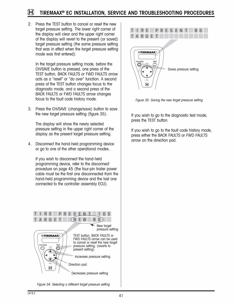
TIREMAAX® EC INSTALLATION, SERVICE AND TROUBLESHOOTING PROCEDURES
41L818 E
2. Press the TEST button to cancel or reset the newtarget pressure setting. The lower right corner ofthe display will clear and the upper right cornerof the display will revert to the present (or saved)target pressure setting (the same pressure settingthat was in effect when the target pressure settingmode was first entered).
In the target pressure setting mode, before theCH/SAVE button is pressed, one press of theTEST button, BACK FAULTS or FWD FAULTS arrowacts as a “reset” or “do over” function. A secondpress of the TEST button changes focus to thediagnostic mode, and a second press of theBACK FAULTS or FWD FAULTS arrow changesfocus to the fault code history mode.
3. Press the CH/SAVE (change/save) button to savethe new target pressure setting (figure 35).
The display will show the newly selectedpressure setting in the upper right corner of thedisplay as the present target pressure setting.
4. Disconnect the hand-held programming deviceor go to one of the other operational modes.
If you wish to disconnect the hand-heldprogramming device, refer to the disconnectprocedure on page 45 (the four-pin trailer powercable must be the first one disconnected from thehand-held programming device and the last oneconnected to the controller assembly ECU).
New targetpressure setting
Increases pressure setting
Decreases pressure setting
Figure 34. Selecting a different target pressure setting
Direction pad
TEST button, BACK FAULTS orFWD FAULTS arrow can be usedto cancel or reset the new targetpressure setting, (reverts topresent setting)
If you wish to go to the diagnostic test mode,press the TEST button.
If you wish to go to the fault code history mode,press either the BACK FAULTS or FWD FAULTSarrow on the direction pad.
Figure 35. Saving the new target pressure setting
Saves pressure setting

TIREMAAX® EC INSTALLATION, SERVICE AND TROUBLESHOOTING PROCEDURES
42L818 E
DIAGNOSTIC TEST OPERATIONThe diagnostic test mode can be used to toggle thetrailer mounted indicator and controller assemblyLED, the delivery solenoid valve and the supply solenoid valve on and off to see if these componentsrespond properly. The diagnostic test mode also displays delivery and supply pressure sensor outputsin psi.
NOTE: Temporarily disconnect (unscrew) a wheelhose at the tee fitting on the wheel afterentering the diagnostic test mode. This willprevent inadvertent tire overinflation duringsolenoid valve response testing when bothsupply and delivery solenoids are opened atthe same time.
When the diagnostic test mode is entered, the displayshows the supply and delivery pressure sensor outputs and the current state of the trailer mountedindicator (figure 36). This screen provides a visualindication that you are in the diagnostic test mode.1. To test the trailer mounted indicator and
controller assembly LED response:
Figure 36. Initial diagnostic test mode display
Press the CH/SAVE (change/save) button totoggle the trailer mounted indicator and LED fromoff to on (figure 37). Press the CH/SAVE buttonagain to toggle from on to off.
The trailer mounted indicator and controllerassembly LED will remain in the last statechosen (either on or off) when the diagnosticfocus is changed in the next step.
Figure 37. Testing the trailer mounted indicator and controllerassembly LED response
Toggles indicator
Display toggles with each press of the CH/SAVE button
Figure 38. Testing the supply solenoid valve (SUP) response
2. Toggles supply solenoid valve (SUP) on or off
Display toggles with each press of the CH/SAVE button
1. Shifts focus to supply solenoid (SUP)

TIREMAAX® EC INSTALLATION, SERVICE AND TROUBLESHOOTING PROCEDURES
43L818 E
2. To test the supply solenoid valve response, pressthe TEST button (figure 38). The diagnostic focusshifts from the indicator to the supply solenoidvalve.
Press the CH/SAVE (change/save) button totoggle the supply solenoid valve from off to on.Press the CH/SAVE button again to toggle thevalve from on to off (figure 38).
CAUTION: Potential overinflation hazard. Whenperforming diagnostics, the trailer airtank pressure MUST NOT be higherthan the target pressure setting.
If the trailer air tank pressure ishigher, the tires will overinflate whenboth supply and delivery solenoidvalves are opened at the same time.No method exists to exhaust theoverinflated tires, other thandisconnecting the tire hoses andmanually depressing the valve stemcore at each tire.
The supply solenoid valve will remain in the laststate chosen (either on or off) when thediagnostic focus is changed in the next step.
3. To test the delivery solenoid valve response,press the TEST button (figure 39). The diagnosticfocus shifts from the supply solenoid valve to thedelivery solenoid valve.
Press the CH/SAVE button to toggle the deliverysolenoid valve from off to on. Press the CH/SAVEbutton again to toggle the valve from on to off(figure 39).
The delivery solenoid valve will remain in the laststate chosen (either on or off) when shifting toanother mode of operation.
When indicator and solenoid valve responsetesting is complete, set all responses to the OFFstate and reconnect the wheel hose at the teefitting.
4. Disconnect the hand-held programming deviceor go to one of the other operational modes.
If you wish to disconnect the hand-heldprogramming device, refer to the disconnect
procedure on page 45 (the four-pin trailer powercable must be the first one disconnected from thehand-held programming device and the last oneconnected to the controller assembly ECU).
If you wish to go to the target pressure settingmode, press the +PSI or -PSI arrow on thedirection pad.
If you wish to go to the fault code history mode,press the BACK FAULTS or FWD FAULTS arrow onthe direction pad.
Figure 39. Testing the delivery solenoid valve (DEL) response
2. Toggles delivery solenoid valve(DEL) on or off
Display toggles with each press of the CH/SAVE button
1. Shifts focus to delivery solenoid (DEL)

TIREMAAX® EC INSTALLATION, SERVICE AND TROUBLESHOOTING PROCEDURES
44L818 E
FAULT CODE HISTORY OPERATIONThe fault code history mode is used to review faultcodes that have been stored in the TIREMAAX® EC controller.
When the fault code history mode is entered, the display will show the last recorded fault (figure 40).This screen provides a visual indication that you arein the fault code history mode.
There are five possible fault codes that can be displayed in the fault code history mode (figure 41).The upper right corner of the fault code display showsthe fault code number. This number will match thenumber of times the LED on the controller assemblyblinks when a fault is detected. The bottom line of thedisplay contains a brief description of the fault. Referto the Blink Code Descriptions section on page 36 foradditional fault details.
1. Press the BACK FAULTS arrow on the directionpad to go back through the six most-recentlyrecorded faults (figure 42).
Figure 40. Initial fault code history mode display
(The X’s are specificto each fault code)
2. Press the FWD FAULTS arrow on the directionpad to go forward through the six most-recentlyrecorded faults (figure 42).
The upper left corner of the display identifies thefault by its relationship to the last fault (figure 42).
After reviewing the fault code history, the nature of thefault can be identified and the following steps can betaken to correct the fault:
a. Disconnect the hand-held programming deviceand reconnect the proper cables to the ECU onthe controller assembly, but do not apply powerto the trailer.
b. Fix the fault and pressurize the trailer air tank toat least five psi above the target pressure.
c. After the trailer air tank is adequately pressurized,apply power to the trailer.
Figure 41. Possible fault codes

TIREMAAX® EC INSTALLATION, SERVICE AND TROUBLESHOOTING PROCEDURES
45L818 E
When the controller is repowered, it will go into itsnormal operating mode. As the controller proceedsthrough its system routines, it will assume the faulthas been corrected.
If the fault was not fixed, the controller will detect itand the LED on the controller assembly will blink thefault code. This LED blink code will be adequate todiagnose issues until resolved, without needing to re-attach the hand-held programming device. Everytime power is removed from the controller and then reapplied, it will assume the fault has been correctedand will not repeat a fault code unless it detects thesame one again.
A fault code will not be stored as a repeated codeunless the same fault is the first one recorded after a power up. If the same fault is displayed in two consecutive locations in the fault code history, thefault was redetected after controller power was reconnected.
Figure 42. Stepping through the fault code history
Steps forward through fault history
Steps backward through fault history
It is not possible to clear faults from the register.When a new fault is detected, it becomes the lastfault and all pre-existing faults shift one location. The last location, the sixth fault, gets overwritten.
3. Disconnect the hand-held programming deviceor go to one of the other operational modes.
If you wish to disconnect the hand-heldprogramming device, refer to the followingdisconnect procedure (the four-pin trailer powercable must be the first one disconnected from thehand-held programming device and the last oneconnected to the controller assembly ECU).
If you wish to go to the target pressure settingmode, press the +PSI or -PSI arrow on thedirection pad.
If you wish to go to the diagnostic test mode,press the TEST button twice. Pressing the TESTbutton once takes you to the target pressuresetting mode. The second press will take you tothe diagnostic test mode.
HAND-HELD PROGRAMMING DEVICEDISCONNECT PROCEDURE1. Unplug the four-pin trailer power cable from the
hand-held programming device. Do not plug thisconnector back into the controller assembly ECUat this time, it will be reconnected in step six.
2. Unplug the six-pin sensor cable from the hand-held programming device.
3. Unplug the hand-held programming device six-pin connector from the controller assembly ECU.
4. Unplug the hand-held programming device four-pin connector from the controller assembly ECU.
5. Plug the six-pin sensor cable back into the six-pin connector on the controller assembly ECU.
6. Plug the four-pin trailer power cable back into thefour-pin connector on the controller assemblyECU.
7. Observe the LED on the controller assembly.Make sure it does not blink a fault codeassociated with loose or leaking tire hoses.

REMOVAL1. Disconnect the five-pin ABS connector
(figure 43).
2. Disconnect the five-pin power supply connector.
3. Disconnect the indicator connection.
4. Disconnect the ECU connector.
INSTALLATION1. Connect the five-pin ABS connector.
2. Connect the five-pin power supply connector.
3. Connect the indicator connector.
4. Connect the ECU connector.
SERVICE PROCEDURESWIRING HARNESS REPLACEMENTTwo wiring harnesses are available with TIREMAAX® EC: a standard, three-wire, 18-inch long harness and a premium, ABS-ready, 15-foot longharness.
With the standard wiring harness, replacement issimply a matter of disconnecting the existing harnessand connecting the new one. On the standard harness, the red wire is the indicator power lead, thewhite wire is vehicle ground and the blue wire is 12VDC vehicle power. The termination of these wires isthe responsibility of the harness installer. Terminalsand connectors must be weatherproof, and corrosionprevention compound must be used on all connectors. Refer to TMC RP 113, 114 and 704 forrecommended wiring practices.
Use the following procedure to replace the premiumwiring harness.
TIREMAAX® EC INSTALLATION, SERVICE AND TROUBLESHOOTING PROCEDURES
46L818 E
Figure 43. Premium wiring harness replacement
Five-pin ABSconnector
Five-pin power supply connector
Premium wiring harness
Indicatorconnection
ECU powerconnector
J560 interface
Indicator
These components not included with TIREMAAX® EC
Use an internal ground or run adedicated ground wire from theindicator to the plug that connectsthe trailer to the tow vehicle.
Alternate style premium,ABS-ready harness

5. If reusing the air line fittings, remove them fromthe tee fittings on the controller assembly.
6. Remove the two bracket-to-frame mounting bolts.
INSTALLATION1. Install the two bracket-to-frame mounting bolts.
2. If necessary, apply thread sealant to air fittings.
3. Install air line fittings on tee fittings.
4. Connect the air IN and air OUT lines to theappropriate ports. Test for air leaks by listeningor using soapy water.
CONTROLLER ASSEMBLY REPLACEMENTThis procedure replaces the controller assembly asone complete unit.
REMOVAL1. Exhaust the trailer air tank.
2. Disconnect the ECU power connector (figure 44).
3. Disconnect the air supply line. Label the line “IN”to avoid confusion when installing the newcontroller assembly.
4. Disconnect the air delivery line. Label the line“OUT” to avoid confusion when the newcontroller assembly is installed.
TIREMAAX® EC INSTALLATION, SERVICE AND TROUBLESHOOTING PROCEDURES
47L818 E
Figure 44. Controller assembly replacement
Mounting bolt
ECU powerconnector
Supply line (air IN)
Delivery line (air OUT)
Controller assembly
Tee fittings

TIREMAAX® EC INSTALLATION, SERVICE AND TROUBLESHOOTING PROCEDURES
48L818 E
5. Connect the ECU connector.
6. Recharge the trailer air system.
7. Manually measure tire pressure. Refer to thesection titled MANUALLY CHECKING TIREPRESSURE on page 6 for complete manual tirepressure measuring instructions.
8. Verify that the target tire pressure matches thedesired operating tire pressure.

ELECTRONIC CONTROL UNIT REPLACEMENTREMOVAL1. Disconnect trailer from power source.
2. Disconnect all three ECU connectors (figure 45).
3. Remove the two ECU-to-bracket mounting screwsand remove the ECU.
INSTALLATION1. Install the replacement ECU and secure with the
two ECU-to-bracket mounting screws andwashers.
2. Connect the ECU connectors.
3. Apply power to the trailer (blue circuit on theseven-pin trailer connector). The replacement
ECU comes from the factory with a pre-set targetpressure. No further programming is requiredunless a target pressure setting other than thefactory setting is desired. In that case a hand-held programming device, available fromHendrickson, can be used to program a newtarget pressure setting.
TIREMAAX® EC INSTALLATION, SERVICE AND TROUBLESHOOTING PROCEDURES
49L818 E
Figure 45. ECU replacement
ECU connectors
Mountingscrews andwashers
ECU

1. Turn vehicle off and disconnect the tire hose(s)at the tee on the hubcap (figure 46).
TIREMAAX® EC INSTALLATION, SERVICE AND TROUBLESHOOTING PROCEDURES
50L818 E
WHEEL REMOVAL AND INSTALLATIONDisable the system before wheel removal. This willeliminate potential faults if the system attempts to checktire pressure while the tire hoses are disconnected.
Figure 46. Tire removal and installation
Outer wheel hoseassembly
Check valve
Inner wheelhose assembly
Rotary joint bulkheadadapter (use onewrench to hold thejam nut stationarywhile tightening the teefitting with a secondwrench)
Tee fitting guard (not to be used as a step)
NOTE: Tire hoses must be connected directly tothe tire valve stems and the tee fitting.Do not use valve stem extenders.
Alternate style teeguard, used onHUS® hubs withbolt-on hubcaps
Dual wheelconfiguration
clock “A”
For 17.5- or 22.5-inch, five-hole or five-spoked wheels
For 19.5- or 24.5-inch, five-hole or five-spoked wheels
For any size, two-hole or four / six-spoked wheels
7 to 8 o’clock
With the hubcap fitting in the 12 o'clock position, the valve stemshould be located between 7 and 8 o'clock for most applications.When the wheel is installed, verify that the tire hose is notstretched so tightly that a strain is introduced at either the valvestem or hubcap fitting. Also make sure the tire hose is not soloose that it contacts the wheel.
This illustration shows the valve stem pointing outboard (towardthe viewer). Other valve stem orientations could be supplied bythe wheel manufacturer. Do not rotate or otherwise alter the orientation of the valve stem as supplied from the wheel manu-facturer. Valve stem orientation is not critical to TIREMAAX performance as long as the hose is routed as noted above.
Check to ensure that no portion of the tire hose extends furtheroutboard than the outer face of the wheel. If this occurs, contactHendrickson for instructions on how to route the hoses to avoidthis.
Dual wheelconfiguration
clock “C”
Dual wheelconfiguration
clock “B”
Super singlewheel
configuration

CAUTION: DO NOT overtighten the knurled tirehose nut. Doing so will bend the tee/ elbow fitting stem and compromisethe integrity of internal tee / elbowfitting components. Do not damageknurled finish on tire hose nut. Doingso will make tire hose removalextremely difficult.
NOTE: Tire hoses must be connected directly to thetire valve stems and the tee fitting. Do not usevalve stem extenders.
8. Attach the tire hose(s) to the tire valve stem(s)and tighten finger tight.
9. Using a 7/16-inch wrench, tighten the tirehose/valve stem connection an additional one-half turn. Do not overtighten this connection.
CAUTION: DO NOT overtighten the tire hose(s)on the tire valve stem(s). Doing somay damage the tire hose internalgasket, causing a leak or decreasedsystem performance. Only tightenthe connection an additional one-half turn with the wrench.
10. If the tee fitting guard was removed, reinstall thetee fitting guard and tighten the hub cap bolts to12 - 18 ft. lbs. (16 - 24 N•m). Check all airsystem connections for leaks using the systemintegrity check found on page 33.
WHEEL-END SERVICE (HUB REMOVAL)When it is necessary to remove the hub, care must betaken to avoid damaging the rotary joint assembly:
• On HP and HUS® spindles (axles with same sizeinner and outer bearings), the hub may beremoved with the rotary joint in place. Follow theWHEEL REMOVAL AND INSTALLATION procedure onthe previous page to remove the wheel. Thenremove the jam nut from the rotary joint bulkheadadapter and remove the hubcap. Finally, removethe hub. If necessary, refer to Hendrickson publication L496, Wheel-End MaintenanceProcedures, for complete hub removal details.
• To remove the hub on HN spindles, the rotary jointmust be detached from the spindle plug, but notcompletely removed from the braided axle hose.
NOTE: There will be no air loss when the tire hosesare disconnected at the tee since a checkvalve is located in each tire hose.
NOTE: Steps 2 through 4 describe the completeremoval of the tee fitting guard and tee fittingwhen removing the wheel. As an alternative,the wheel can be removed with the tee fittingguard and tee fitting still installed on thehubcap as long as the wheel assembly isrotated so that the tee fitting is in the sixo’clock position. With the tee fitting in the sixo’clock position, it is more protected frompotential damage when the wheel assemblydrops down onto the hub after clearing thewheel studs. Note that if a wheel dolly is beingused, the wheel must be lowered to clear thetee fitting.
2. Remove the two hubcap bolts securing the teefitting guard to the wheel end and remove the tee fitting guard.
NOTE: The tee fitting guard may not be used on allTIREMAAX® EC systems. For example, it is notused on HUS® hubs with screw-on hubcaps.
3. Remove the tee from the hubcap fitting. Cover(plug) the hubcap fitting to preventcontamination from entering the system.
4. On dual-wheel configurations, observe andrecord the orientation of the wheel to the hubbefore removal of the wheel (clock A, B, or C.Refer to figure 46).
5. Remove and reinstall the wheel. Take care not todamage the hubcap fitting. Make sure the wheelis properly oriented to the hub as indicated infigure 46.
6. If the tee fitting was removed, reinstall the teefitting and tighten the swivel threads to 130 ±10in. lbs. of torque. Refer to the TIRE HOSEINSTALLATION procedure on page 30 forcomplete tee fitting and tire hose tighteningdetails.
7. Attach tire hose and check valve assemblies tothe tee or elbow fitting and tighten finger tight(figure 24). Using pliers, carefully and gentlyverify that the hose connection is tight.
TIREMAAX® EC INSTALLATION, SERVICE AND TROUBLESHOOTING PROCEDURES
51L818 E

ROTARY JOINT REATTACHMENT1. When hub / wheel-end service is complete, re-
attach the rotary joint to the spindle plug byinstalling the three T20 Torx fasteners andtightening to 45 ±5 in. lbs. (5 ±½ N•m) oftorque.
2. Rotate the rotary joint exit tube one fullrevolution. Make sure that the steel air tube doesnot contact any part of the spindle or spindle nutsystem.
HUBCAP ASSEMBLY1. Place hubcap gasket over rotary joint exit tube
and bulkhead adapter.
2. Lubricate O-ring on the rotary joint bulkheadadapter. Use the same lubricant as is used in thehub or a light film of #2 grease, white lithiumgrease or Vaseline®.
3. From the inside, insert the bulkhead adapterthrough the hole in the hubcap labeled “Air”. Alignthe flat on the bulkhead adapter with the anti-rotation flat in the hubcap (figure 15). Note theorientation indicator on the top of the bulkheadadapter threads (figure 15, view a). Use thisindicator (some models have a dot, other modelshave a notch) to properly orient the bulkheadadapter in the hubcap hole. When the flat on thebulkhead adapter is properly aligned with theanti-rotation flat in the hubcap, the orientationindicator will face outboard (figure 15, view b).
Do not use pliers or any kind of wrench to pullthe bulkhead adapter up through the hole in the
TIREMAAX® EC INSTALLATION, SERVICE AND TROUBLESHOOTING PROCEDURES
52L818 E
While detached from the spindle plug, the rotaryjoint can be moved, tipped or otherwise manipulated so the hub can clear it and beremoved. There is no need to disconnect the rotaryjoint from the braided axle hose. Follow the WHEELREMOVAL AND INSTALLATION procedure on the previous page to remove the wheel, then use thefollowing procedure to detach the rotary joint forhub removal:
ROTARY JOINT DETACHMENT (FOR HUBREMOVAL ON HN SPINDLES)1. Remove the jam nut from the rotary joint bulk-
head adapter and remove the hubcap (figure 47).
2. Remove the three fasteners holding the rotaryjoint assembly to the spindle plug (figure 48).
3. When detached, the rotary joint can be moved,tipped or otherwise manipulated so the spindlenuts, outer bearing and hub can clear the rotaryjoint and be removed. DO NOT disconnect therotary joint from the braided axle hose.
Figure 47. Hubcap to bulkhead adapter removal
Rotary joint assembly
Hubcap
Jam nut
Bulkheadadapter
Spindle
figure 48. Rotary joint removal from spindle
T20 Torxfasteners

TIREMAAX® EC INSTALLATION, SERVICE AND TROUBLESHOOTING PROCEDURES
53L818 E
hubcap. This could cause the bulkhead adapterto rotate before it engages the flat in thehubcap, potentially damaging the rotary unionor hubcap.
Attach the jam nut and hand tighten. Whenproperly seated, the top of the bulkhead adapterwill be flush (or higher) with the top of the jamnut when hand tightened (figure 15, view c).
CAUTION: Wheel must be properly “clocked” tothe hubcap to prevent the hosesfrom rubbing on the wheel (figure23). Failure to properly “clock” thewheels may result in hose failure.
4. Install the hubcap. If the hubcap is a screw-onstyle used on the HUS hub, tighten it to 50-100ft. lbs. (68-137 N•m) of torque. If the hubcap isa bolt-on style used on the other hubs, tightenthe hubcap bolts to 12-18 ft. lbs. (16-24 N•m)of torque.
5. Tighten the rotary joint jam nut to 15 ft. lbs. (20 N•m) of torque.
6. Refer to the TIRE HOSE INSTALLATION section onpage 30 to complete the reassembly.
GLOSSARYTIREMAAX® EC Tire Inflation System — A systemthat maintains the pressure of selected tires and activates a warning to alert the vehicle operator if thepressure drops by more than 20 psi.
Electronic Control Unit (ECU) — The ECU is programmed with the target tire pressure and directsthe system to supply air to the tires when needed. A significant drop in tire pressure causes the ECU toilluminate the indicator.
Rotary Joint — Rotary air seal assembly that allowsair transfer from wheel end to tire(s) while vehicle isin motion. The rotary joint is only pressurized whilethe system is checking tire pressure or inflating.
Target Tire Pressure — The desired tire pressure.
Bulkhead Adapter — The threaded portion of therotary union assembly that gets inserted through thehubcap from the inside.
Controller Assembly — Consists of the ECU, mount-ing bracket, solenoid valves and pressure sensorsand controls the flow of air from the onboard air tankto the tires.
Axle Vent — On INTRAAX / VANTRAAX suspensions,the axle vent is the remaining hole in the axle wrapwindow. On Hendrickson Trailer Axles, the axle ventis the hole in the midpoint of the axle, equidistantfrom each spindle end. In both cases, it vents theaxle to atmospheric pressure through a duck billcheck valve.
System Integrity Check — A manual air leak test orcheck of all connections in the TIREMAAX system. Itmust be accomplished after installation and beforeputting the vehicle into service. It is done by manually pressurizing the TIREMAAX system throughthe controller assembly vent tube from a shop airsupply and applying soapy water to all connectionsto check for leaks.
Controller Assembly Vent Tube — A ¼ inch nylontube that extends through the controller assemblymounting bracket and originates from the deliveryside solenoid.

TIREMAAX® EC INSTALLATION, SERVICE AND TROUBLESHOOTING PROCEDURES
54L818 E

TIREMAAX® EC INSTALLATION, SERVICE AND TROUBLESHOOTING PROCEDURES
55L818 E
APPENDIX
figure 49. Typical tire maintenance system performance at 100 psig
Ambient temperature when the target tire pressure is set
For example: Target tire pressure is set to 100 psi in Little Rock, Arkansas, where the air temperature is 70degrees F. The trailer is then driven to International Falls, Minnesota, where the air temperature is 20 degreesF. Instead of 100 psi, the pressure in the tires is now 89 psi, due solely to the effects of temperature on pressure.
-40 -30 -20 -10 0 10 20 30 40 50 60 70 80 90 100 110 120
120
110
100
90
80
70
60
50
40
30
20
10
0
TIRE PRESSURE VS. TEMPERATURE
Temperature (ºF)
Pres
sure
(PS
IG)
Drops to 89 psig at 20º F(warning lamp comes on)
Set 100 psig at 70º F
68
70
72
74
76
78
80
82
84
86
88
90
92
94
96
98
100
120
70
72
74
76
78
80
82
84
86
88
90
92
94
96
98
100
102
110
71
73
75
77
79
82
84
86
88
90
92
94
96
98
100
102
104
100
74
77
79
81
83
85
87
89
91
94
96
98
100
102
104
106
109
80
76
78
81
83
85
87
89
91
94
96
98
100
102
104
106
109
111
70
78
80
82
85
87
89
91
93
96
98
100
102
104
107
109
111
113
60
80
82
84
86
89
91
93
95
98
100
102
105
107
109
111
114
116
50
100
103
105
108
111
114
116
119
122
125
127
130
133
136
138
141
144
-40
-40
-30
-20
-10
0
10
20
30
40
50
60
70
80
90
100
110
120
97
100
103
105
108
111
113
116
119
121
124
127
129
132
135
137
140
-30
-95
97
100
103
105
108
110
113
116
118
121
123
126
129
131
134
137
-20
92
95
97
100
103
105
108
110
113
115
118
120
123
126
128
131
133
-10
90
93
95
98
100
102
105
107
110
112
115
117
120
122
125
127
130
0
88
90
93
95
98
100
102
105
107
110
112
115
117
120
122
124
127
10
86
88
90
93
95
98
100
102
105
107
110
112
114
117
119
122
124
20
84
86
88
91
93
95
98
100
102
105
107
109
112
114
116
119
121
30
82
84
86
89
91
93
95
98
100
102
105
107
109
111
114
116
118
40
73
75
77
79
81
83
85
87
90
92
94
96
98
100
102
104
106
90Am
bien
t tem
pera
ture
whe
n tir
e pr
essu
re is
mea
sure
d
NOTE: Temperature values in chart above are only for 100 psi target tire pressure.

www.hendrickson-intl.com
Information contained in this literature was accurate at the time of publication. Product changes may have been made after the copyright date that are not reflected.© 2007 Hendrickson USA, L.L.C. (U.S. Rights) Hendrickson International Corporation (Rights Outside U.S.) All Rights ReservedL818 Rev E 10-07 ECN 16066
Trailer Suspension Systems250 Chrysler Drive, Unit #3Brampton, ON Canada L6S 6B6905.789.1030Fax 905.789.1033
Trailer Suspension SystemsAve. Rogelio González Caballero #850-B Parque Industrial Stiva Apodaca, N.L., C.P. 66600 México(52) 81 8156 1300Fax (52) 81 8156 1301
Trailer Suspension Systems2070 Industrial Place SECanton, OH 44707-2641 USA
866.RIDEAIR (743.3247)330.489.0045Fax 800.696.4416
Printed in United States of America