technical reference manual - library.e.abb.com · technical reference manual 4. instructions 4.1....
TRANSCRIPT

Overcurrent and Earth-Fault RelayREJ 525
Technical Reference Manual


Overcurrent and Earth-Fault Relay Technical Reference Manual
REJ 5251MRS750941-MUM
Issued: 14.09.1998Version: D/14.11.2005
Contents1. About this manual ...................................................................5
1.1. Copyrights ...................................................................................51.2. Trademarks .................................................................................51.3. Guarantee ...................................................................................51.4. General ........................................................................................51.5. Use of symbols ............................................................................61.6. Terminology .................................................................................61.7. Related documents .....................................................................61.8. Document revisions .....................................................................6
2. Safety Information ...................................................................73. Introduction .............................................................................9
3.1. Use of the relay ...........................................................................93.2. Features ......................................................................................9
4. Instructions ............................................................................114.1. Application .................................................................................114.2. Requirements ............................................................................114.3. Configuration .............................................................................11
5. Technical description ...........................................................155.1. Functional description ...............................................................15
5.1.1. Product functions ...........................................................155.1.1.1. Schema of product functions ............................155.1.1.2. Overcurrent, phase discontinuity and
earth-fault .........................................................155.1.1.3. Inputs ...............................................................165.1.1.4. Outputs .............................................................165.1.1.5. Circuit-breaker failure protection unit ...............165.1.1.6. Disturbance recorder ........................................165.1.1.7. HMI module ......................................................165.1.1.8. Non-volatile memory ........................................175.1.1.9. Self-supervision ................................................17
5.1.2. Measurements ...............................................................185.1.3. Configuration ..................................................................185.1.4. Protection .......................................................................19
5.1.4.1. Block diagram ..................................................195.1.4.2. Overcurrent unit ...............................................195.1.4.3. Phase discontinuity protection unit ...................205.1.4.4. Earth-fault unit ..................................................205.1.4.5. Time/current characteristics .............................21
3
1MRS750941-MUMOvercurrent and Earth-Fault Relay Technical Reference Manual
REJ 525
5.1.4.6. Settings ............................................................ 305.1.4.7. Technical data on protection functions ............ 38
5.1.5. Indicator LEDs and alarm indication messages ............. 395.1.6. Monitoring of demand values ......................................... 405.1.7. Commissioning test ....................................................... 405.1.8. Disturbance recorder ..................................................... 40
5.1.8.1. Function ........................................................... 405.1.8.2. Disturbance recorder data ............................... 415.1.8.3. Control and indication of disturbance
recorder status ................................................. 425.1.8.4. Triggering ......................................................... 425.1.8.5. Settings and unloading .................................... 425.1.8.6. Event code of the disturbance recorder ........... 43
5.1.9. Recorded data of the last events ................................... 435.1.10.External serial communication ....................................... 44
5.1.10.1.Communication ports ....................................... 445.1.10.2.IEC 60870-5-103 remote communication
protocol ............................................................ 455.1.10.3.Event codes ..................................................... 485.1.10.4.SPA bus communication protocol parameters . 50
5.1.11.Self-supervision (IRF) system ........................................ 585.1.12.Relay parameterization .................................................. 58
5.2. Design description .................................................................... 585.2.1. Input/output connections ................................................ 585.2.2. Serial communication connections ................................ 615.2.3. Technical data .............................................................. 62
6. Ordering information ............................................................ 677. Abbreviations ........................................................................ 698. Check lists ......................................................................... 719. Service ................................................................................... 7510. Index ...................................................................................... 77
4

1MRS750941-MUM REJ 525Overcurrent and Earth-Fault Relay Technical Reference Manual
1. About this manual
1.1. CopyrightsThe information in this document is subject to change without notice and should not be construed as a commitment by ABB Oy. ABB Oy assumes no responsibility for any errors that may appear in this document.
In no event shall ABB Oy be liable for direct, indirect, special, incidental or consequential damages of any nature or kind arising from the use of this document, nor shall ABB Oy be liable for incidental or consequential damages arising from use of any software or hardware described in this document.
This document and parts thereof must not be reproduced or copied without written permission from ABB Oy, and the contents thereof must not be imparted to a third party nor used for any unauthorized purpose.
The software or hardware described in this document is furnished under a license and may be used, copied, or disclosed only in accordance with the terms of such license.
Copyright © 2005 ABB Oy All rights reserved.
1.2. TrademarksABB is a registered trademark of ABB Group.All other brand or product names mentioned in this document may be trademarks or registered trademarks of their respective holders.
1.3. GuaranteePlease inquire about the terms of guarantee from your nearest ABB representative.
1.4. GeneralThe purpose of this manual is to provide the user with thorough information on the protection relay REJ 525 and its applications, focusing on giving a technical description of the relay.
Refer to the Operators Manual for instructions on how to use the Human-Machine Interface (HMI) of the relay, also known as the Man-Machine Interface (MMI), and to the Installation Manual for installation of the relay.
5
1MRS750941-MUMOvercurrent and Earth-Fault Relay Technical Reference Manual
REJ 525
1.5. Use of symbolsThis document includes warning, caution, and information icons that point out safety-related conditions or other important information. The corresponding icons should be interpreted as follows:
Although warning hazards are related to personal injury, and caution hazards are associated with equipment or property damage, it should be understood that operation of damaged equipment could, under certain operational conditions, result in degraded process performance leading to personal injury or death. Therefore, comply fully with all warning and caution notices.
1.6. TerminologyThe following is a list of terms that you should be familiar with. The list contains terms that are unique to ABB or have a usage or definition that is different from standard industry usage.
1.7. Related documents
1.8. Document revisions
The electrical warning icon indicates the presence of a hazard which could result in electrical shock.
The caution icon indicates important information or warning related to the concept discussed in the text. It might indicate the presence of a hazard which could result in corruption of software or damage to equipment or property.
The information icon alerts the reader to relevant facts and conditions.
Term DescriptionIEC_103 IEC 60870-5-103, a communication protocol standardized by the
International Electrotechnical CommissionSPA A data communication protocol developed by ABB
Name of the manual MRS numberREJ 525 Operators Manual 1MRS752137-MUMRE_ 5__ Installation Manual 1MRS750526-MUM
Version Date HistoryC 23.03.2004D 14.11.2005 Relay face plate updated.
Manual layout updated.
6

1MRS750941-MUM REJ 525Overcurrent and Earth-Fault Relay Technical Reference Manual
2. Safety Information
Dangerous voltages can occur on the connectors, even though the auxiliary voltage has been disconnected.Non-observance can result in death, personal injury or substantial property damage.Only a competent electrician is allowed to carry out the electrical installation.National and local electrical safety regulations must always be followed.The frame of the device has to be carefully earthed.The device contains components which are sensitive to electrostatic discharge. Unnecessary touching of electronic components must therefore be avoided.Breaking the sealing tape on the rear panel of the device will result in loss of warranty and proper operation will no longer be guaranteed.
7

8
1MRS750941-MUM REJ 525Overcurrent and Earth-Fault Relay Technical Reference Manual
3. Introduction
3.1. Use of the relay The combined overcurrent and earth-fault relay REJ 525 is intended for selective short-circuit protection and non-directional earth-fault protection in medium voltage distribution networks but can also be used for protection of generators, motors and transformers.
The REJ 525 is based on a microprocessor environment. A self-supervision system continuously monitors the operation of the relay.
The HMI includes a Liquid Crystal Display (LCD) which makes the local use of the relay safe and easy.
Local control of the relay via serial communication can be carried out with a portable computer connected to the front connector and remote control via the rear connector connected to the distribution automation system through the serial interface and the fibre-optic bus.
3.2. Features Three-phase low-set overcurrent stage with definite-time or inverse definite
minimum time (IDMT) characteristic Three-phase high-set overcurrent stage with instantaneous or definite-time
characteristic Phase discontinuity protection Low-set non-directional earth-fault stage with definite-time or IDMT
characteristic High-set non-directional earth-fault stage with instantaneous or definite-time
characteristic Circuit-breaker failure protection (CBFP) Disturbance recorder
recording time up to 10 seconds triggering by a start or a trip signal from any protection stage and/or by a binary
input signal records four analogue channels and up to eight user-selectable digital channels adjustable sampling rate
Non-volatile memory for up to 60 event codes setting values disturbance recorder data recorded data of the five last events with time stamp number of starts for each stage alarm indication messages and LEDs showing the status at the moment of
power failure maximum pick-up currents
9
1MRS750941-MUMOvercurrent and Earth-Fault Relay Technical Reference Manual
REJ 525
Four accurate current inputs Galvanically isolated binary input with a wide input voltage range All settings can be modified with a personal computer HMI with an alphanumeric LCD and manoeuvring buttons IEC 60870-5-103 and SPA bus communication protocols Two normally open power output contacts Two change-over signal output contacts Output contact functions freely configurable for desired operation Optical PC-connector for two-way data communication (front) RS-485 connector (rear) for system communication Continuous self-supervision of electronics and software. At an internal relay fault
(IRF), all protection stages and outputs are blocked. User-selectable rated frequency 50/60 Hz User-selectable password protection for the HMI Display of primary current values Demand values Multi-language support
10
1MRS750941-MUM REJ 525Overcurrent and Earth-Fault Relay Technical Reference Manual
4. Instructions
4.1. ApplicationThe combined overcurrent and earth-fault relay REJ 525 is a secondary relay which is connected to the current transformers of the object to be protected. The overcurrent and the earth-fault unit continuously measure the phase currents and the neutral current of the object. On detection of a fault, the relay will start, trip the circuit breaker, provide alarms, record fault data, etc., in accordance with the application and the configured relay functions.
The overcurrent unit includes low-set stage I> and high-set stage I>> and the earth-fault unit low-set stage I0> and high-set stage I0>>. If the high-set stage is given a setting value within the lower part of the setting range, the relay module will have two nearly identical stages. In this case, the relay can be used in two-stage load shedding applications.
The protection functions are independent of each other and have their own setting groups and data recordings. The overcurrent and earth-fault protection functions use conventional current transformer measurement.
An output contact matrix allows start or trip signals from the protection stages to be routed to the desired output contact.
4.2. Requirements When the REJ 525 is operating under the conditions specified below (see also Technical data), it will be practically maintenance-free. The relay includes no parts or components subject to abnormal physical or electrical wear under normal operating conditions.
Environmental conditions
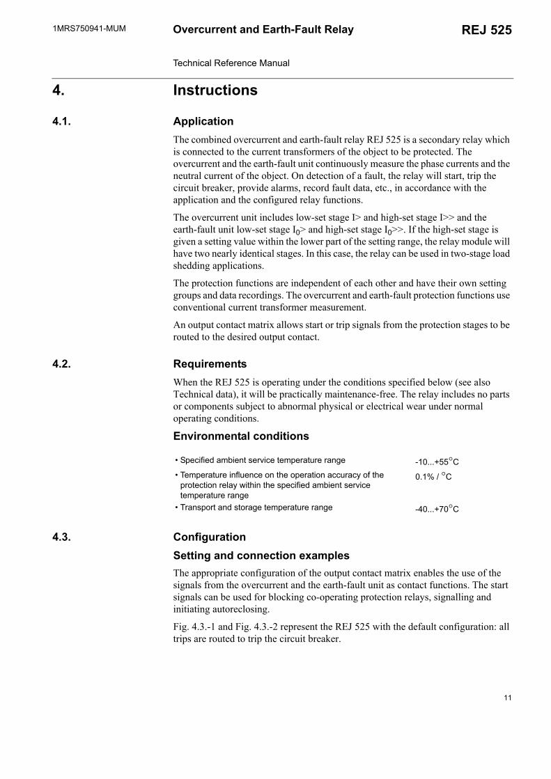
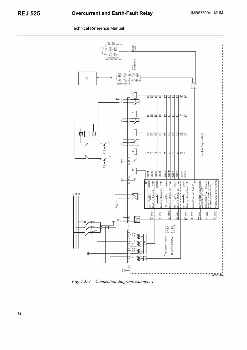
4.3. ConfigurationSetting and connection examplesThe appropriate configuration of the output contact matrix enables the use of the signals from the overcurrent and the earth-fault unit as contact functions. The start signals can be used for blocking co-operating protection relays, signalling and initiating autoreclosing.
Fig. 4.3.-1 and Fig. 4.3.-2 represent the REJ 525 with the default configuration: all trips are routed to trip the circuit breaker.
Specified ambient service temperature range -10...+55°C Temperature influence on the operation accuracy of the
protection relay within the specified ambient service temperature range
0.1% / °C
Transport and storage temperature range -40...+70°C
11
1MRS750941-MUMOvercurrent and Earth-Fault Relay Technical Reference Manual
REJ 525
A0501414
Fig. 4.3.-1 Connection diagram, example 1
!
"
!
"
!
"
#
#
$
%
&
&
&
&
&
&
&
&!
&%
&%
&%
&%
'
%
%(
)
)
'
%
%(
)
)#
&%
&%
&%
"&%
&
&"
&%
*+,-.
,/+012-0
%. -3,/4 25+40
%. -3,/4 25+40
%. -3,/4 25+40
%. -3,/4 25+40
)$-+ 16702
.+
01,.
* 1+
$
%. -3,/4 25+40
87 8
7
#8 #8
97
878
7#
7
: 9&
8
;7<
87
87#
7=
8
8
97
*+ ->.0
12
1MRS750941-MUM REJ 525Overcurrent and Earth-Fault Relay Technical Reference Manual
A0501415
Fig. 4.3.-2 Connection diagram, example 2
$
!
"
!
"
!
"
#
#
%
$
&
&
&
&
&
&
&
&!
&%
&%
&%
&%
'
%
%(
)
)
'
%
%(
)
)#
&
&"
&%
&%
&%
&%
"
&%
*+,-.
,/+012-0
%. -3,/4 25+40
%. -3,/4 25+40
%. -3,/4 25+40
%. -3,/4 25+40
01,.
* 1+
)$-+ 16702.+
%. -3,/4 25+40
87 8
7
#8 #8
97
878
7#
7
: 9&
8
;7<
87
87#
7=
8
8
97
*+ ->.0
13

14

1MRS750941-MUM REJ 525Overcurrent and Earth-Fault Relay Technical Reference Manual
5. Technical description
5.1. Functional description
5.1.1. Product functions
5.1.1.1. Schema of product functions
A0501416
Fig. 5.1.1.1.-1 Product functions
5.1.1.2. Overcurrent, phase discontinuity and earth-faultRefer to sections:
5.1.4.1. Overcurrent unit 5.1.4.3. Phase discontinuity protection unit 5.1.4.4. Earth-fault unit
8
8
!%$
$
!
?100*?50@02,/,+0+,A0 1,/B0150+,A0. C50+ B01-110/+*1 +0-+, /
702,/,+0+,A0 1,/B0150+,A0. C50+01+?2.+*1 +0-+, /
01,.- AA/,-+, /
?100*?50,/5+/+/0 5 1@02,/,+0+,A0?,4?50+ B01-110/+*1 +0-+, /
/5+/+/0 5 1@02,/,+0+,A0?,4?50+01+?2.+*1 +0-+, /
,1-,+>103012,.10*1 +0-+, /
0A +01050+D10A +050++,/4- /+1 . 1>. -3,/4,/*+2 1+?0@,22010/+*1 +0-+, /5+405
?50@,5- /+,/,+6*1 +0-+, /
%,/16,/*+%
*+,-.*-,/+012-0
15
1MRS750941-MUMOvercurrent and Earth-Fault Relay Technical Reference Manual
REJ 525
5.1.1.3. InputsThe REJ 525 includes four energizing inputs and one external binary input controlled by an external voltage. Three of the energizing inputs are for the phase currents and one for the earth-fault current. For details, refer to Section 5.2.1. Input/output connections and tables 5.1.4.6-7, 5.2.1-1 and 5.2.1-5. The function of the binary input is determined with the SGB switches.
5.1.1.4. OutputsThe REJ 525 is provided with two power outputs (PO1 and PO2) and two signal outputs (SO1 and SO2). Switchgroups SGR1...10 are used for routing start and trip signals from the protection stages to the desired signal or power output. PO1 and PO2 can be configured to be latched and the minimum pulse length to 40 or 80 ms.
5.1.1.5. Circuit-breaker failure protection unitThe REJ 525 features a circuit-breaker failure protection (CBFP) unit. The CBFP unit will generate a trip signal via output PO2 if the fault has not been cleared on expiration of the set operate time 0.10 s...1.00 s.
Normally, the CBFP unit controls the upstream circuit breaker. It can also be used for tripping via redundant trip circuits of the same circuit breaker. The CBFP unit is activated with a switch of switchgroup SGF1.
5.1.1.6. Disturbance recorder The REJ 525 includes an internal disturbance recorder which records the momentary measured values, or the RMS curves of the measured signals, and up to eight user-selectable digital signals: the external binary input signal and the states of the internal protection stages. The disturbance recorder can be set to be triggered by a start or a trip signal from any protection stage and/or by an external binary input signal, and either on the falling or rising triggering edge.
5.1.1.7. HMI moduleThe HMI of the REJ 525 is equipped with six push-buttons and an alphanumeric 2x16 characters LCD. The push-buttons are used for navigating in the menu structure and for adjusting set values.
An HMI password can be set to protect all user-changeable values from being changed by an unauthorised person. The HMI password will remain inactive and will thus not be required for altering parameter values until the default HMI password has been replaced. Entering the HMI password successfully can be selected to generate an event code. This feature can be used to indicate interaction activities via the local HMI. For further information on the HMI, refer to the Operators Manual.
16
1MRS750941-MUM REJ 525Overcurrent and Earth-Fault Relay Technical Reference Manual
5.1.1.8. Non-volatile memoryThe REJ 525 can be configured to store various data in a non-volatile memory, which will retain its data also in case of loss of auxiliary voltage. Alarm indication messages and LEDs, the number of starts, disturbance recorder data, event codes and recorded data can all be configured to be stored in the non-volatile memory whereas setting values will always be stored.
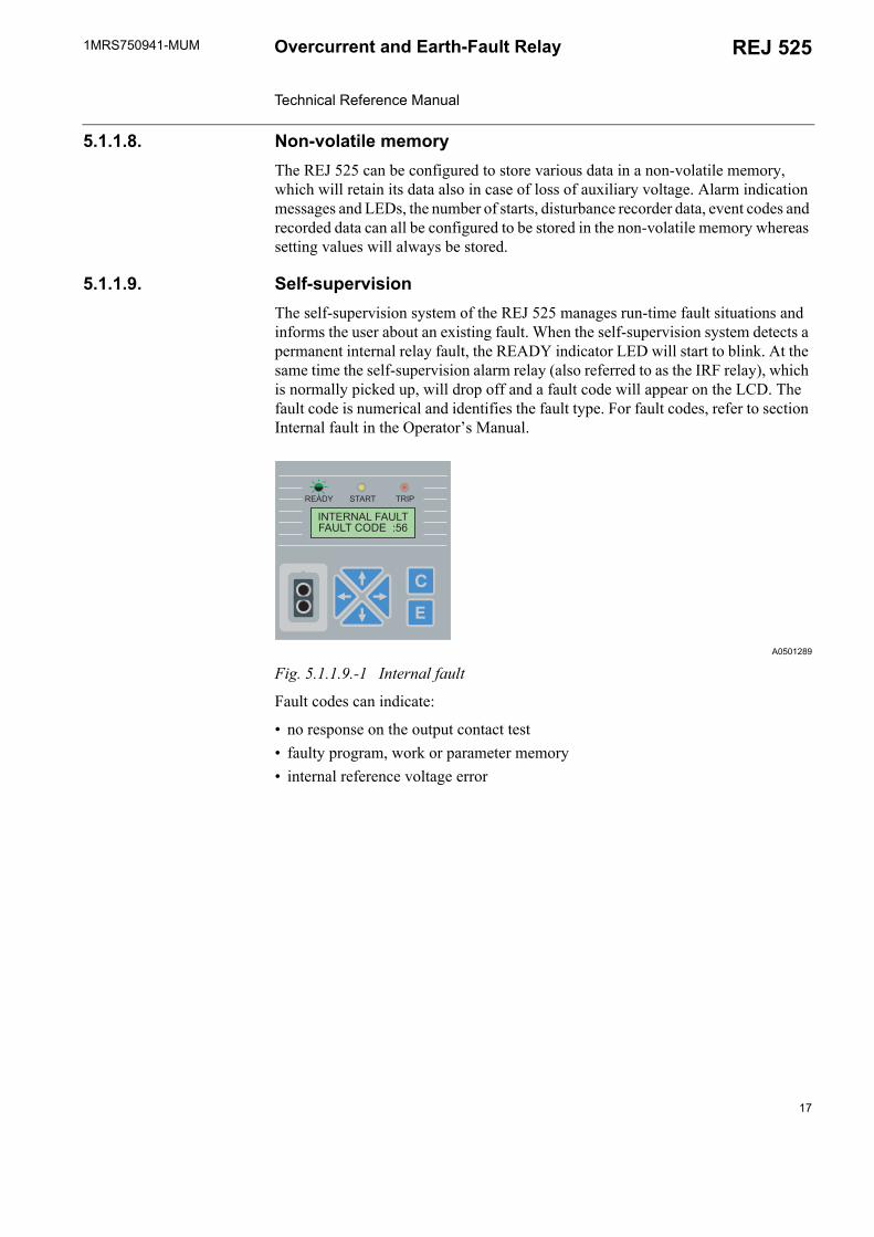
5.1.1.9. Self-supervisionThe self-supervision system of the REJ 525 manages run-time fault situations and informs the user about an existing fault. When the self-supervision system detects a permanent internal relay fault, the READY indicator LED will start to blink. At the same time the self-supervision alarm relay (also referred to as the IRF relay), which is normally picked up, will drop off and a fault code will appear on the LCD. The fault code is numerical and identifies the fault type. For fault codes, refer to section Internal fault in the Operators Manual.
A0501289
Fig. 5.1.1.9.-1 Internal fault
Fault codes can indicate:
no response on the output contact test faulty program, work or parameter memory internal reference voltage error
7E
8 8$ $ 7(!
17
1MRS750941-MUMOvercurrent and Earth-Fault Relay Technical Reference Manual
REJ 525
5.1.2. MeasurementsThe table below presents the measured values which can be accessed through the HMI, expressed as multiples of the rated voltage, In, of the energizing input.
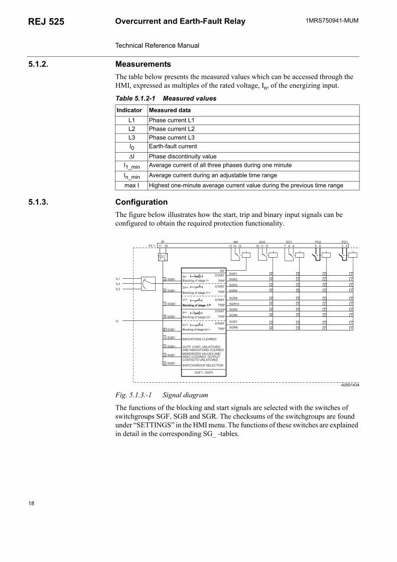
5.1.3. ConfigurationThe figure below illustrates how the start, trip and binary input signals can be configured to obtain the required protection functionality.
A0501434
Fig. 5.1.3.-1 Signal diagram
The functions of the blocking and start signals are selected with the switches of switchgroups SGF, SGB and SGR. The checksums of the switchgroups are found under SETTINGS in the HMI menu. The functions of these switches are explained in detail in the corresponding SG_ -tables.
Table 5.1.2-1 Measured values
Indicator Measured dataL1 Phase current L1L2 Phase current L2L3 Phase current L3I0 Earth-fault current
∆I Phase discontinuity valueI1_min Average current of all three phases during one minute
In_min Average current during an adjustable time range
max I Highest one-minute average current value during the previous time range
"# " !
!
$ %
&$###&$
&%
&%
&%
&%
&
&
&
&!
&
&
&
&
&%
&%
&%
" &%
&%
&
&"
%. -3,/4 25+40
%. -3,/4 25+40
%. -3,/4 25+40
%. -3,/4 25+40
$
%. -3,/4 25+40
87 87
#8 #8 978787 87;7<8787#7= 8 8 97
: 9& 8
%. -3,/4 25+40
18
1MRS750941-MUM REJ 525Overcurrent and Earth-Fault Relay Technical Reference Manual
5.1.4. Protection
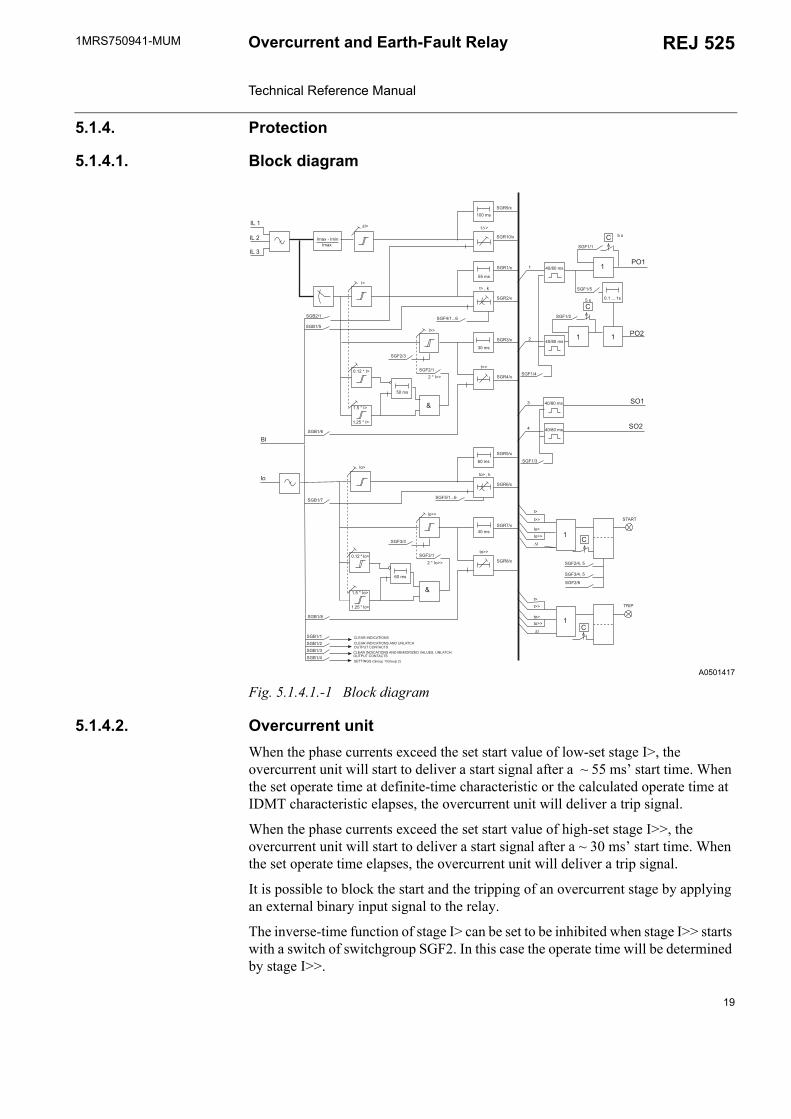
5.1.4.1. Block diagram
A0501417
Fig. 5.1.4.1.-1 Block diagram
5.1.4.2. Overcurrent unitWhen the phase currents exceed the set start value of low-set stage I>, the overcurrent unit will start to deliver a start signal after a ~ 55 ms start time. When the set operate time at definite-time characteristic or the calculated operate time at IDMT characteristic elapses, the overcurrent unit will deliver a trip signal.
When the phase currents exceed the set start value of high-set stage I>>, the overcurrent unit will start to deliver a start signal after a ~ 30 ms start time. When the set operate time elapses, the overcurrent unit will deliver a trip signal.
It is possible to block the start and the tripping of an overcurrent stage by applying an external binary input signal to the relay.
The inverse-time function of stage I> can be set to be inhibited when stage I>> starts with a switch of switchgroup SGF2. In this case the operate time will be determined by stage I>>.
#
#
#
F
&$
&
&
&
&
+D3
&%!
%
+
&%
#
#
#
F
&$
&
&"
&!
&
+ D3
&$###!
+
&%
&%"
&%
&%
&%
+
+
+
+
A5
!A5
A5
!A5
A5
&$
&$
&$###!
&$D
&$D
A5
+
&
&
A5
&%
5
&$
"A5
&$
5
"A5
&$
####5
&$
&$
"A5
"A5
&%
AA,/A
&$!
87 8878 9 8
87 887;7<D8 9 8
87 8
8&G&1 *&1 *H
19

1MRS750941-MUMOvercurrent and Earth-Fault Relay Technical Reference Manual
REJ 525
The high-set stage can be set out of operation. This state will be indicated by dashes on the LCD and by 999 when the set start value is read via serial communication.
The set start value of stage I>>, I>>/In, can be automatically doubled in a start situation, e.g. when the object to be protected is connected to a distribution network. Thus a set start value below the connection inrush current level can be selected for stage I>>. A start situation is defined as a situation where the phase current rises from a value below 0.12 x I> to a value above 1.5 x I> in less than 60 ms. The start situation ends when the current falls below 1.25 x I>.
5.1.4.3. Phase discontinuity protection unitThe phase discontinuity protection function monitors the minimum and maximum phase currents and calculates the difference between them. The difference between these currents is calculated as follows:
The phase discontinuity protection stage will start when the current difference exceeds the start value, ∆I, of the protection stage. Should the phase discontinuity situation last longer than the set operate time, the protection stage will deliver a trip signal which can be routed to the desired output contact. It is possible to block the start and the tripping of the protection stage by applying an external binary input signal to the relay. When the values of the measured currents fall below 0.1 x In, the function will no longer be in use.
The phase discontinuity function can be set out of operation. This state will be indicated by dashes on the LCD and 999 when the set start value is read via serial communication.
5.1.4.4. Earth-fault unitWhen the earth-fault current exceeds the set start value of low-set stage I0>, the earth-fault unit will start to deliver a start signal after a ~ 60 ms start time. When the set operate time at definite-time characteristic or the calculated operate time at IDMT characteristic elapses, the earth-fault unit will deliver a trip signal.
When the earth fault current exceeds the set start value of high-set stage I0>>, the earth-fault unit will start to deliver a start signal after a ~ 40 ms start time. When the set operate time elapses, the earth-fault unit will deliver a trip signal.
It is possible to block the start and the tripping of an earth-fault stage by applying an external binary input signal to the relay.
The inverse-time function of stage I0> can be set to be inhibited when stage I0>> starts with a switch of switchgroup SGF2. In this case the operate time will be determined by stage I0>>.
The high-set stage can be set out of operation. This state will be indicated by dashes on the LCD and by 999 when the set start value is read via serial communication.
∆I Imax Imin( )Imax
----------------------------------- 100%×=
20
1MRS750941-MUM REJ 525Overcurrent and Earth-Fault Relay Technical Reference Manual
The set start value of stage I0>>, I0>>/In, can be automatically doubled in a start situation, e.g. when the object to be protected is connected to a distribution network. Thus a set start value below the connection inrush current level can be selected for stage I0>>. A start situation is defined as a situation where the earth-fault current rises from a value below 0.12 x I0> to a value above 1.5 x I0> in less than 60 ms. The start situation ends when the current falls below 1.25 x I0>.
5.1.4.5. Time/current characteristicsThe low-set overcurrent and earth-fault stages can be given a definite-time or an inverse definite minimum time (IDMT) characteristic whereas the high-set overcurrent and earth-fault stages feature the definite-time characteristic alone. The settings of switches SGF4/1...6 determine the operation mode of stage I> whereas those of switches SGF5/1...6 determine that of stage I0>. Refer to section Settings for additional information.
At IDMT characteristic, the operate time of the stage is dependent on the current value: the higher the current value, the shorter the operate time. Six time/current curve groups are available, of which four comply with the IEC 60255 standard: the normal inverse, very inverse, extremely inverse and long-time inverse. The two additional inverse-time curve groups, referred to as RI and RD, are special curve groups according to ABB praxis.
Characteristics according to the IEC 60255 standardThe relay module incorporates four internationally standardized time/current curve groups called extremely inverse, very inverse, normal inverse and long-time inverse. The relationship between time and current is in accordance with the IEC 60255-3 standard and can be expressed as follows:
where
t = operate timek = time multiplierI = phase current valueI> = set start value
According to the standard, the normal current range is 2...20 times the setting value at normal inverse, very inverse or extremely inverse characteristic. The relay is to start before the current exceeds the setting value by 1.3 times. At long-time inverse
Table 5.1.4.5-1 The values of constants α and β
Time/current curve group α β
Normal inverse 0.02 0.14Very inverse 1.0 13.5Extremely inverse 2.0 80.0Long-time inverse 1.0 120
t s ][ k β×I
I>----- α
1-----------------------=
21
1MRS750941-MUMOvercurrent and Earth-Fault Relay Technical Reference Manual
REJ 525
characteristic, the normal current range is specified to be 2...7 times the setting value, and the relay is to start before the current exceeds the setting value by 1.1 times.
Within the normal current range the inverse-time stage fulfils the tolerance requirements of class 5 at all degrees of inversity.
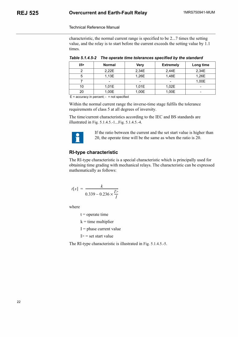
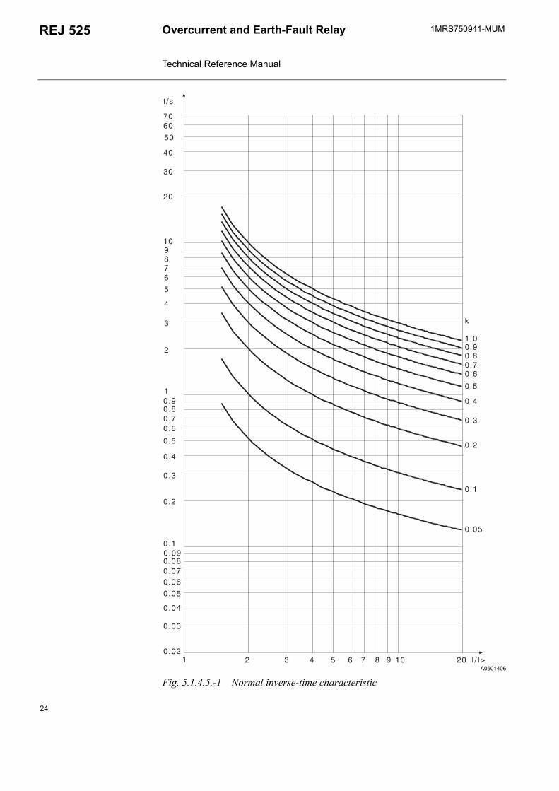
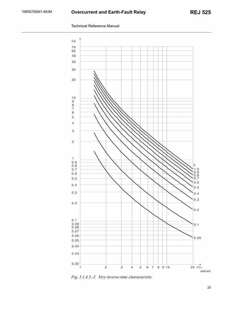
The time/current characteristics according to the IEC and BS standards are illustrated in Fig. 5.1.4.5.-1...Fig. 5.1.4.5.-4.
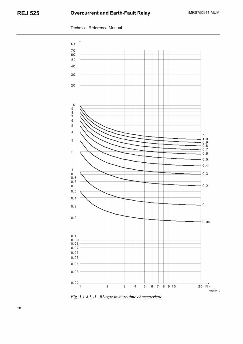
RI-type characteristicThe RI-type characteristic is a special characteristic which is principally used for obtaining time grading with mechanical relays. The characteristic can be expressed mathematically as follows:
where
t = operate timek = time multiplierI = phase current valueI> = set start value
The RI-type characteristic is illustrated in Fig. 5.1.4.5.-5.
Table 5.1.4.5-2 The operate time tolerances specified by the standard
I/I> Normal Very Extremely Long time2 2,22E 2,34E 2,44E 2,34E5 1,13E 1,26E 1,48E 1,26E7 - - - 1,00E10 1,01E 1,01E 1,02E -20 1,00E 1,00E 1,00E -
E = accuracy in percent; - = not specified
If the ratio between the current and the set start value is higher than 20, the operate time will be the same as when the ratio is 20.
t s[ ] k
0.339 0.236 I>I
-----×---------------------------------------------=
22

1MRS750941-MUM REJ 525Overcurrent and Earth-Fault Relay Technical Reference Manual
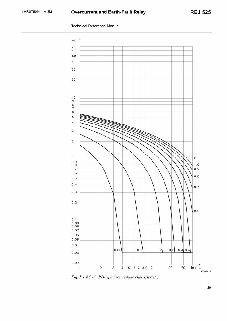
RD-type characteristicThe RD-type characteristic is a special characteristic which is principally used in earth-fault protection and which requires a high degree of selectivity even at high resistance faults. The protection can operate in a selective way even if it is not directional. Mathematically, the time/current characteristic can be expressed as follows:
where
t = operate timek = time multiplierI = phase current valueI> = set start value
The RD-type characteristic is illustrated in Fig. 5.1.4.5.-6.
t s ][ 5.8 1.35 loge× Ik I>×-------------- =
23
1MRS750941-MUMOvercurrent and Earth-Fault Relay Technical Reference Manual
REJ 525
A0501406
Fig. 5.1.4.5.-1 Normal inverse-time characteristic
24
1MRS750941-MUM REJ 525Overcurrent and Earth-Fault Relay Technical Reference Manual
A0501407
Fig. 5.1.4.5.-2 Very inverse-time characteristic
25

1MRS750941-MUMOvercurrent and Earth-Fault Relay Technical Reference Manual
REJ 525
A0501408
Fig. 5.1.4.5.-3 Extremely inverse-time characteristic
26
1MRS750941-MUM REJ 525Overcurrent and Earth-Fault Relay Technical Reference Manual
A0501409
Fig. 5.1.4.5.-4 Long-time inverse-time characteristic
27
1MRS750941-MUMOvercurrent and Earth-Fault Relay Technical Reference Manual
REJ 525
A0501410
Fig. 5.1.4.5.-5 RI-type inverse-time characteristic
28
1MRS750941-MUM REJ 525Overcurrent and Earth-Fault Relay Technical Reference Manual
A0501411
Fig. 5.1.4.5.-6 RD-type inverse-time characteristic
29
1MRS750941-MUMOvercurrent and Earth-Fault Relay Technical Reference Manual
REJ 525
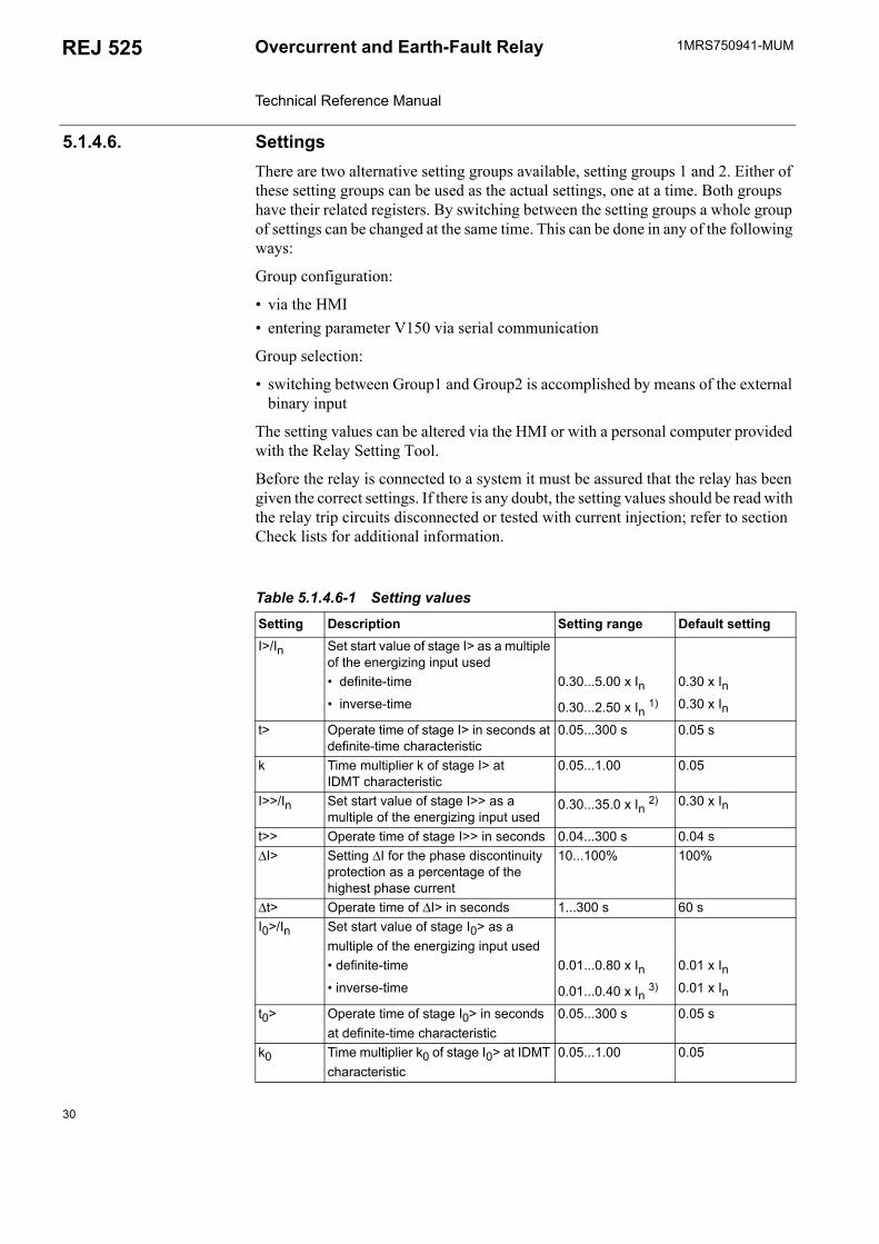
5.1.4.6. SettingsThere are two alternative setting groups available, setting groups 1 and 2. Either of these setting groups can be used as the actual settings, one at a time. Both groups have their related registers. By switching between the setting groups a whole group of settings can be changed at the same time. This can be done in any of the following ways:
Group configuration:
via the HMI entering parameter V150 via serial communication
Group selection:
switching between Group1 and Group2 is accomplished by means of the external binary input
The setting values can be altered via the HMI or with a personal computer provided with the Relay Setting Tool.
Before the relay is connected to a system it must be assured that the relay has been given the correct settings. If there is any doubt, the setting values should be read with the relay trip circuits disconnected or tested with current injection; refer to section Check lists for additional information.
Table 5.1.4.6-1 Setting values
Setting Description Setting range Default settingI>/In Set start value of stage I> as a multiple
of the energizing input used definite-time 0.30...5.00 x In 0.30 x In inverse-time 0.30...2.50 x In 1) 0.30 x In
t> Operate time of stage I> in seconds at definite-time characteristic
0.05...300 s 0.05 s
k Time multiplier k of stage I> at IDMT characteristic
0.05...1.00 0.05
I>>/In Set start value of stage I>> as a multiple of the energizing input used
0.30...35.0 x In 2) 0.30 x In
t>> Operate time of stage I>> in seconds 0.04...300 s 0.04 s∆I> Setting ∆I for the phase discontinuity
protection as a percentage of the highest phase current
10...100% 100%
∆t> Operate time of ∆I> in seconds 1...300 s 60 sI0>/In Set start value of stage I0> as a
multiple of the energizing input used definite-time 0.01...0.80 x In 0.01 x In inverse-time 0.01...0.40 x In 3) 0.01 x In
t0> Operate time of stage I0> in seconds at definite-time characteristic
0.05...300 s 0.05 s
k0 Time multiplier k0 of stage I0> at IDMT characteristic
0.05...1.00 0.05
30
1MRS750941-MUM REJ 525Overcurrent and Earth-Fault Relay Technical Reference Manual
1) At IDMT characteristic, the REJ 525 allows settings above 2.5 x In for stage I>, but regards any setting > 2.5 x In as equal to 2.5 x In.
2) The stage can be set out of operation in SGF. This state will be indicated by dashes on the LCD and by "999" when parameters are read via the SPA bus.
3) At IDMT characteristic, the REJ 525 allows settings above 0.4 x In for stage I0, but regards any setting >0.4 x In as equal to 0.4 x In.
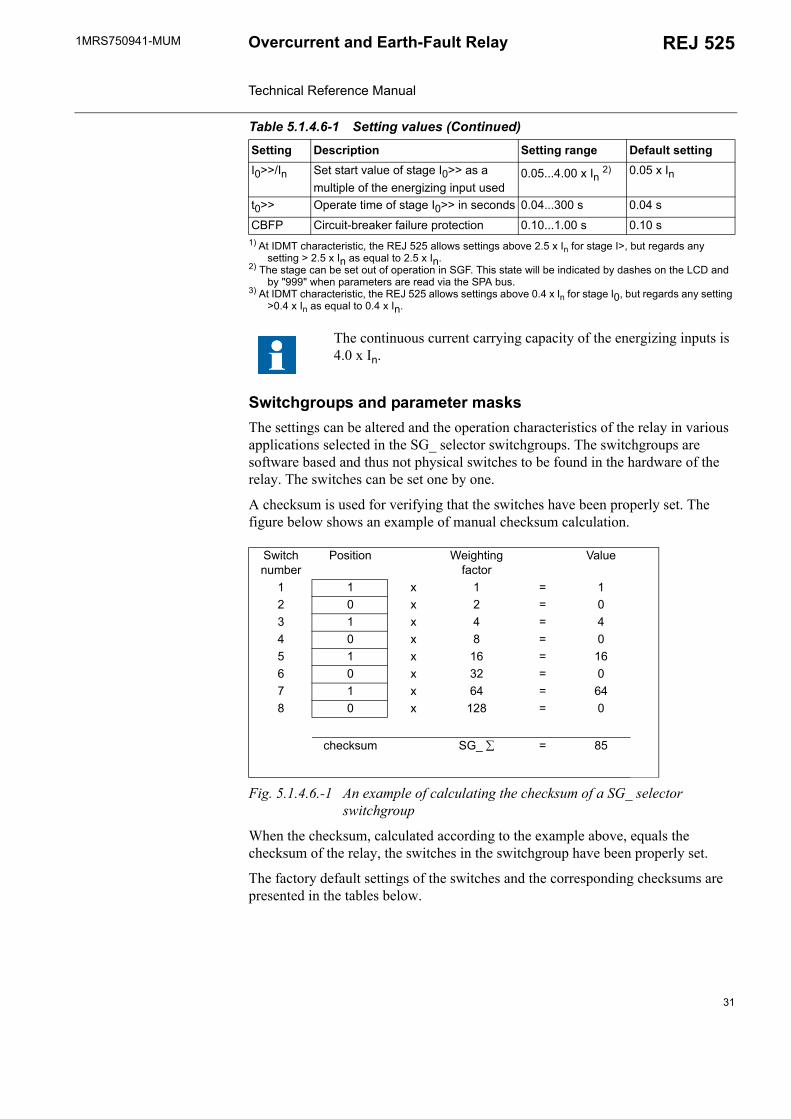
Switchgroups and parameter masksThe settings can be altered and the operation characteristics of the relay in various applications selected in the SG_ selector switchgroups. The switchgroups are software based and thus not physical switches to be found in the hardware of the relay. The switches can be set one by one.
A checksum is used for verifying that the switches have been properly set. The figure below shows an example of manual checksum calculation.
Fig. 5.1.4.6.-1 An example of calculating the checksum of a SG_ selector switchgroup
When the checksum, calculated according to the example above, equals the checksum of the relay, the switches in the switchgroup have been properly set.
The factory default settings of the switches and the corresponding checksums are presented in the tables below.
I0>>/In Set start value of stage I0>> as a multiple of the energizing input used
0.05...4.00 x In 2) 0.05 x In
t0>> Operate time of stage I0>> in seconds 0.04...300 s 0.04 s
CBFP Circuit-breaker failure protection 0.10...1.00 s 0.10 s
The continuous current carrying capacity of the energizing inputs is 4.0 x In.
Switch number
Position Weighting factor
Value
1 1 x 1 = 12 0 x 2 = 03 1 x 4 = 44 0 x 8 = 05 1 x 16 = 166 0 x 32 = 07 1 x 64 = 648 0 x 128 = 0
checksum SG_ ∑ = 85
Table 5.1.4.6-1 Setting values (Continued)
Setting Description Setting range Default setting
31
1MRS750941-MUMOvercurrent and Earth-Fault Relay Technical Reference Manual
REJ 525
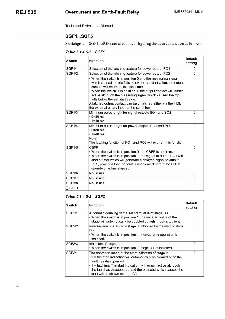
SGF1...SGF5Switchgroups SGF1...SGF5 are used for configuring the desired function as follows:
Table 5.1.4.6-2 SGF1
Switch Function Default setting
SGF1/1 Selection of the latching feature for power output PO1 0SGF1/2 Selection of the latching feature for power output PO2 0
When the switch is in position 0 and the measuring signal which caused the trip falls below the set start value, the output contact will return to its initial state.
When the switch is in position 1, the output contact will remain active although the measuring signal which caused the trip falls below the set start value.
A latched output contact can be unlatched either via the HMI, the external binary input or the serial bus.
SGF1/3 Minimum pulse length for signal outputs SO1 and SO2 0=80 ms 1=40 ms
0
SGF1/4 Minimum pulse length for power outputs PO1 and PO2 0=80 ms 1=40 msNote! The latching function of PO1 and PO2 will overrun this function.
0
SGF1/5 CBFP When the switch is in position 0, the CBFP is not in use. When the switch is in position 1, the signal to output PO1 will
start a timer which will generate a delayed signal to output PO2, provided that the fault is not cleared before the CBFP operate time has elapsed.
0
SGF1/6 Not in use 0SGF1/7 Not in use 0SGF1/8 Not in use 0∑ SGF1 0
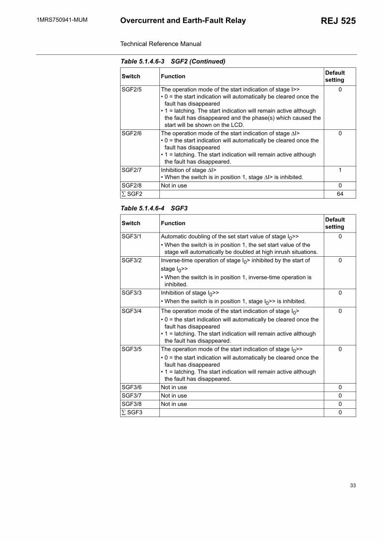
Table 5.1.4.6-3 SGF2
Switch Function Default setting
SGF2/1 Automatic doubling of the set start value of stage I>> When the switch is in position 1, the set start value of the
stage will automatically be doubled at high inrush situations.
0
SGF2/2 Inverse-time operation of stage I> inhibited by the start of stage I>> When the switch is in position 1, inverse-time operation is
inhibited.
0
SGF2/3 Inhibition of stage I>> When the switch is in position 1, stage I>> is inhibited.
0
SGF2/4 The operation mode of the start indication of stage I> 0 = the start indication will automatically be cleared once the
fault has disappeared 1 = latching. The start indication will remain active although
the fault has disappeared and the phase(s) which caused the start will be shown on the LCD.
0
32
1MRS750941-MUM REJ 525Overcurrent and Earth-Fault Relay Technical Reference Manual
SGF2/5 The operation mode of the start indication of stage I>> 0 = the start indication will automatically be cleared once the
fault has disappeared 1 = latching. The start indication will remain active although
the fault has disappeared and the phase(s) which caused the start will be shown on the LCD.
0
SGF2/6 The operation mode of the start indication of stage ∆I> 0 = the start indication will automatically be cleared once the
fault has disappeared 1 = latching. The start indication will remain active although
the fault has disappeared.
0
SGF2/7 Inhibition of stage ∆I> When the switch is in position 1, stage ∆I> is inhibited.
1
SGF2/8 Not in use 0∑ SGF2 64
Table 5.1.4.6-4 SGF3
Switch Function Default setting
SGF3/1 Automatic doubling of the set start value of stage I0>> When the switch is in position 1, the set start value of the
stage will automatically be doubled at high inrush situations.
0
SGF3/2 Inverse-time operation of stage I0> inhibited by the start of stage I0>> When the switch is in position 1, inverse-time operation is
inhibited.
0
SGF3/3 Inhibition of stage I0>> When the switch is in position 1, stage I0>> is inhibited.
0
SGF3/4 The operation mode of the start indication of stage I0> 0 = the start indication will automatically be cleared once the
fault has disappeared 1 = latching. The start indication will remain active although
the fault has disappeared.
0
SGF3/5 The operation mode of the start indication of stage I0>> 0 = the start indication will automatically be cleared once the
fault has disappeared 1 = latching. The start indication will remain active although
the fault has disappeared.
0
SGF3/6 Not in use 0SGF3/7 Not in use 0SGF3/8 Not in use 0∑ SGF3 0
Table 5.1.4.6-3 SGF2 (Continued)
Switch Function Default setting
33
1MRS750941-MUMOvercurrent and Earth-Fault Relay Technical Reference Manual
REJ 525
1) Default setting
1) Default setting
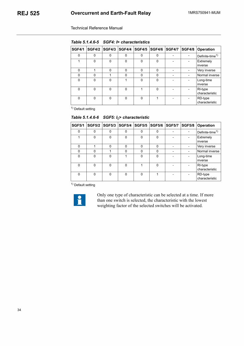
Table 5.1.4.6-5 SGF4: I> characteristics
SGF4/1 SGF4/2 SGF4/3 SGF4/4 SGF4/5 SGF4/6 SGF4/7 SGF4/8 Operation0 0 0 0 0 0 - - Definite-time1)
1 0 0 0 0 0 - - Extremely inverse
0 1 0 0 0 0 - - Very inverse0 0 1 0 0 0 - - Normal inverse0 0 0 1 0 0 - - Long-time
inverse0 0 0 0 1 0 - - RI-type
characteristic0 0 0 0 0 1 - - RD-type
characteristic
Table 5.1.4.6-6 SGF5: I0> characteristic
SGF5/1 SGF5/2 SGF5/3 SGF5/4 SGF5/5 SGF5/6 SGF5/7 SGF5/8 Operation0 0 0 0 0 0 - - Definite-time1)
1 0 0 0 0 0 - - Extremely inverse
0 1 0 0 0 0 - - Very inverse0 0 1 0 0 0 - - Normal inverse0 0 0 1 0 0 - - Long-time
inverse0 0 0 0 1 0 - - RI-type
characteristic0 0 0 0 0 1 - - RD-type
characteristic
Only one type of characteristic can be selected at a time. If more than one switch is selected, the characteristic with the lowest weighting factor of the selected switches will be activated.
34

1MRS750941-MUM REJ 525Overcurrent and Earth-Fault Relay Technical Reference Manual
SGB1
SGB2
SGR1...SGR10The start and trip signals from the protection stages are connected to the output contacts with the switches of switchgroups SGR1...SGR10.
The matrix below can be of help when making the desired selections. The start and trip signals from the different protection stages are combined with the output contacts by encircling the desired intersection point. Each intersection point is marked with a switch number, and the corresponding weighting factor of the switch
Table 5.1.4.6-7 SGB1 Resetting/blocking with BI
Switch Function Default setting
SGB1/1 0 = indications are not cleared by the binary input signal 1 = indications are cleared by the binary input signal
0
SGB1/2 0 = indications are not cleared and latched output contacts are not unlatched by the binary input signal
1 = indications are cleared and latched output contacts are unlatched by the binary input signal
0
SGB1/3 0 = indications and memorized values are not cleared and latched output contacts are not unlatched by the binary input signal
1 = indications and memorized values are cleared and latched output contacts are unlatched by the binary input signal
0
SGB1/4 Switching between setting groups 1 and 2 using the external binary input 0 = the setting group cannot be changed using the external
binary input 1 = the currently used setting group is determined by the
binary input. When the binary input is energized, setting group 2 will be activated.
Note!When SGB1/4 is set to 1, it is important that the switch has the same setting in both setting groups.
0
SGB1/5 Blocking of stage I> by the binary input signal 0SGB1/6 Blocking of stage I>> by the binary input signal 0SGB1/7 Blocking of stage I0> by the binary input signal 0
SGB1/8 Blocking of stage I0>> by the binary input signal When SGB1/5...8=1, tripping of the stage will be blocked by
the external binary input signal.
0
∑ SGB1 0
Table 5.1.4.6-8 SGB2
Switch Function Default setting
SGB2/1 Blocking of stage ∆I> by the binary input signal 0∑ SGB2 0
35

1MRS750941-MUMOvercurrent and Earth-Fault Relay Technical Reference Manual
REJ 525
is shown on the bottom line of the matrix. The switchgroup checksum is obtained by horizontally adding the weighting factors of all the selected switches of the switchgroup.
A0501418
Fig. 5.1.4.6.-2 Output signal matrix
Table 5.1.4.6-9 SGR1...SGR10
Switch Function Default setting
SGR1/1...4 I> signal to output contacts PO1, PO2, SO1 and SO2 12SGR2/1...4 t> signal to output contacts PO1, PO2, SO1 and SO2 3SGR3/1...4 I>> signal to output contacts PO1, PO2, SO1 and SO2 12SGR4/1...4 t>> signal to output contacts PO1, PO2, SO1 and SO2 3SGR5/1...4 I0> signal to output contacts PO1, PO2, SO1 and SO2 12
SGR6/1...4 t0> signal to output contacts PO1, PO2, SO1 and SO2 3
SGR7/1...4 I0>> signal to output contacts PO1, PO2, SO1 and SO2 12
SGR8/1...4 t0>> signal to output contacts PO1, PO2, SO1 and SO2 3
SGR9/1...4 ∆I> signal to output contacts PO1, PO2, SO1 and SO2 12SGR10/1...4 ∆t> signal to output contacts PO1, PO2, SO1 and SO2 3
!"#$%&
'$% '$% '$% '$%
($&$%& !"
36
1MRS750941-MUM REJ 525Overcurrent and Earth-Fault Relay Technical Reference Manual
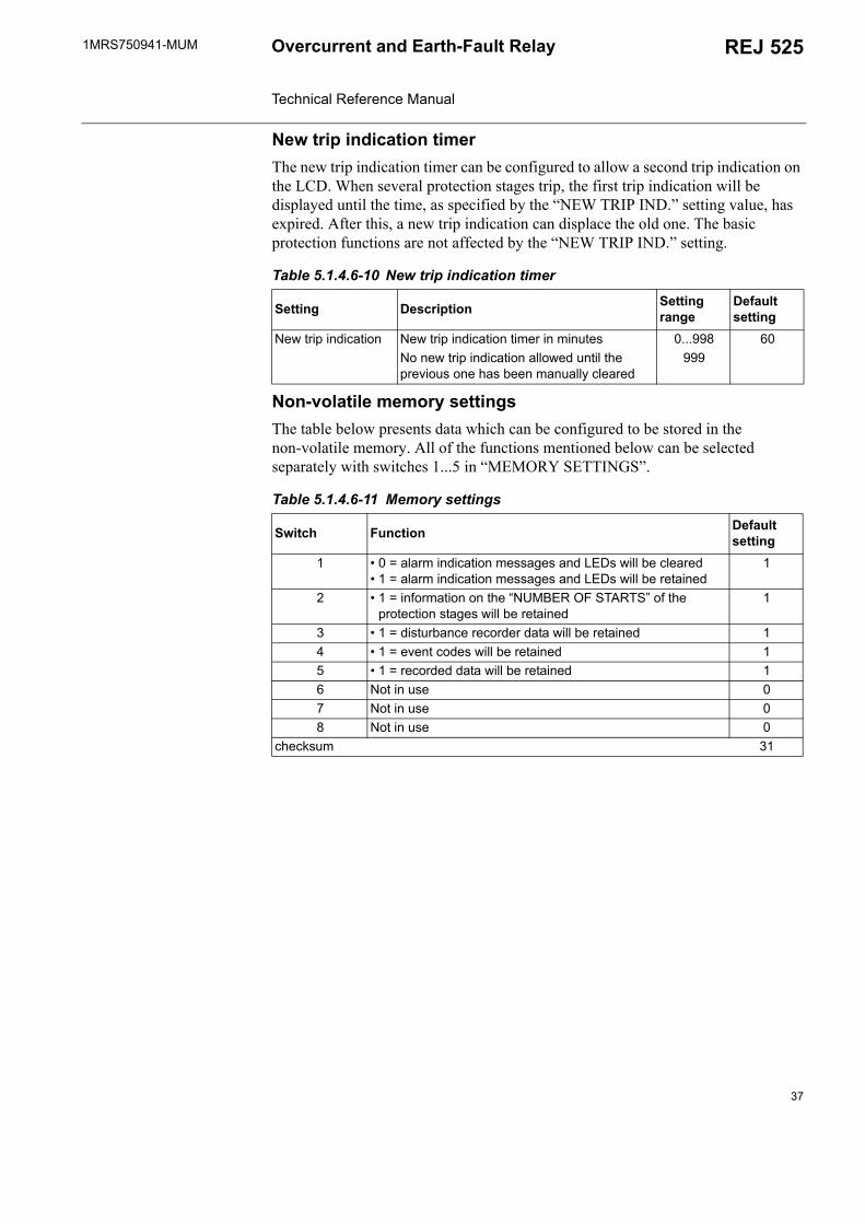
New trip indication timerThe new trip indication timer can be configured to allow a second trip indication on the LCD. When several protection stages trip, the first trip indication will be displayed until the time, as specified by the NEW TRIP IND. setting value, has expired. After this, a new trip indication can displace the old one. The basic protection functions are not affected by the NEW TRIP IND. setting.
Non-volatile memory settingsThe table below presents data which can be configured to be stored in the non-volatile memory. All of the functions mentioned below can be selected separately with switches 1...5 in MEMORY SETTINGS.
Table 5.1.4.6-10 New trip indication timer
Setting Description Setting range
Default setting
New trip indication New trip indication timer in minutes 0...998 60No new trip indication allowed until the previous one has been manually cleared
999
Table 5.1.4.6-11 Memory settings
Switch Function Default setting
1 0 = alarm indication messages and LEDs will be cleared 1 = alarm indication messages and LEDs will be retained
1
2 1 = information on the NUMBER OF STARTS of the protection stages will be retained
1
3 1 = disturbance recorder data will be retained 14 1 = event codes will be retained 15 1 = recorded data will be retained 16 Not in use 07 Not in use 08 Not in use 0
checksum 31
37
1MRS750941-MUMOvercurrent and Earth-Fault Relay Technical Reference Manual
REJ 525
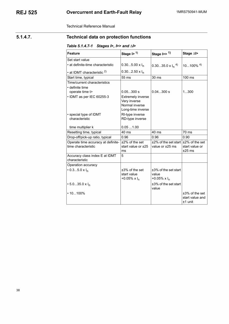
5.1.4.7. Technical data on protection functions
Table 5.1.4.7-1 Stages I>, I>> and ∆I>
Feature Stage I> 1) Stage I>> 1) Stage ∆I>
Set start value at definite-time characteristic 0.30...5.00 x In 0.30...35.0 x In 4) 10...100% 4)
at IDMT characteristic 2) 0.30...2.50 x InStart time, typical 55 ms 30 ms 100 msTime/current characteristics definite time
operate time t> 0.05...300 s 0.04...300 s 1...300 IDMT as per IEC 60255-3 Extremely inverse
Very inverseNormal inverse Long-time inverse
special type of IDMT characteristic
time multiplier k
RI-type inverse RD-type inverse
0.05 ...1.00Resetting time, typical 40 ms 40 ms 70 msDrop-off/pick-up ratio, typical 0.96 0.96 0.90Operate time accuracy at definite-time characteristic
±2% of the set start value or ±25 ms
±2% of the set start value or ±25 ms
±2% of the set start value or ±25 ms
Accuracy class index E at IDMT characteristic
5
Operation accuracy 0.3...5.0 x In ±3% of the set
start value+0.05% x In
±3% of the set start value+0.05% x In
5.0...35.0 x In ±3% of the set start value
10...100% ±3% of the set start value and ±1 unit
38

1MRS750941-MUM REJ 525Overcurrent and Earth-Fault Relay Technical Reference Manual
1) The start and the tripping of the low-set stage at IDMT characteristic can be blocked by the starting of the high-set stage, provided that this function has been selected in SGF. If set in SGF, the operate time will be determined by the set operate time of the high-set stage at heavy fault currents. In order to obtain a trip signal, the high-set stage must be routed to PO1 or PO2.
2) At IDMT characteristic, the relay allows settings above 2.5 x In for stage I>, but regards any setting > 2.5 x In as equal to 2.5 x In.
3) At IDMT characteristic, the relay allows settings above 0.4 x In for stage I0>, but regards any setting > 0.4 x In as equal to 0.4 x In.
4) The stage can be set out of operation in SGF. This state will be indicated by dashes on the LCD and by 999 when parameters are read via the SPA bus.
5.1.5. Indicator LEDs and alarm indication messagesThe operation of the REJ 525 can be monitored by means of three indicators on the front panel of the relay: a green READY indicator LED, a yellow START indicator LED and a red TRIP indicator LED (refer to the Operators Manual for a more thorough presentation).
In addition, in case of an alarm from a protection stage, a text message will appear on the LCD.
Table 5.1.4.7-2 Stages I0> and I0>>
Feature Stage I0> 1) Stage I0>> 1)
Set start value at definite-time characteristic 0.01...0.80 x In 0.05...4.00 x In 4)
at IDMT characteristic 3) 0.01...0.40 x InStart time, typical 60 ms 40 msTime/current characteristics definite time
operate time t0>0.05...300 s 0.04...300 s
IDMT as per IEC 60255-3 Extremely inverseVery inverseNormal inverseLong-time inverse
special type of inverse-time characteristic
time multiplier k
RI-type inverseRD-type inverse
0.05 ...1.00Resetting time, typical 40 ms 40 msDrop-off/pick-up ratio, typical 0.96 0.96Operate time accuracy at definite-time characteristic
±2% of the set start value or ±25 ms
±2% of the set start value or ±25 ms
Accuracy class index E at IDMT characteristic
5
Operation accuracy 0.01...0.8 x In ±3% of the set start
value+0.05% x In
±3% of the set start value+0.05% x In
0.8...4.0 x In ±3% of the set start value
39
1MRS750941-MUMOvercurrent and Earth-Fault Relay Technical Reference Manual
REJ 525
The messages on the LCD have a certain priority order. If different types of indications are activated simultaneously, the message with the highest priority will appear on the LCD.
The priority order of the messages:
1. CBFP2. TRIP3. START
5.1.6. Monitoring of demand valuesThe REJ 525 provides three different kinds of demand values. The first value shows the average current of all three phases measured during one minute. The value is updated once a minute. The second value shows the average current during an adjustable time range, ranging from 0 to 999 minutes, with an accuracy of one minute. This value is updated at the expiration of each time range. The third value shows the highest one-minute average current value measured during the previous time range. However, if the time range is set to zero, only the one-minute and the maximum demand value will be shown. The maximum value is the highest one-minute mean value since the last reset.
The demand values can be set to zero by resetting the relay or through communication using a V parameter. The demand values will also be reset if V135, M80 or M83 is changed.
5.1.7. Commissioning testThe function test is used for testing the configuration as well as the connections to and from the relay. By selecting this test the ten internal signals from the protection stages and the IRF function can be activated and tested one by one. Provided that the internal signals from the protection stages have been set to be routed to the output contacts (PO1, PO2, SO1 and SO2) with the switches of SGR1...10, the output contacts will be activated and the corresponding event codes generated when the test is run. The test will not generate protection function event codes. Additionally, if the CBFP function is in use and PO1 is activated, PO2 will be activated, too.
The state of the binary input can be monitored by selecting the binary input test, and the LEDs can be turned on by selecting the LED test. Refer to the Operators Manual for more detailed instructions on how to perform the tests.
5.1.8. Disturbance recorder
5.1.8.1. FunctionThe REJ 525 features an integrated disturbance recorder for recording monitored quantities. The recorder continuously captures the curve forms of the currents as well as the status of both the internal signals and the external binary input signal and stores these in the memory.
40
1MRS750941-MUM REJ 525Overcurrent and Earth-Fault Relay Technical Reference Manual
Triggering of the recorder will generate an event code. After the recorder has been triggered, it will continue to record data for a pre-defined post-triggering time. An asterisk will be shown on the LCD on completion of the recording. The status of the recording can also be viewed using a SPA parameter.
As soon as the recorder has been triggered and the recording has finished, the recording can be uploaded and analyzed by means of a PC provided with a special program.
5.1.8.2. Disturbance recorder dataOne recording contains data from the four analogue channels and up to eight digital channels for a preselected time. The analogue channels, whose data is stored either as RMS curves or as momentary measured values, are the currents measured by the relay. The digital channels, referred to as digital signals, are the start and trip signals from the protection stages and the external binary input signal linked to the relay.
The user can select up to eight digital signals to be recorded. The start or trip signal from any protection stage and/or the external binary input signal can be selected. If more than eight signals are selected, the first eight signals will be stored, starting with the internal signals followed by the external signal. The digital signals to be stored are selected with parameters V238 and V239; see tables 5.1.10.4-5 and 5.1.10.4-6.
The recording length varies according to the selected sampling frequency. The RMS curve is recorded by selecting the sampling frequency to be the same as the nominal frequency of the relay. The sampling frequency is selected with parameter M15; see the table below for details.
1) RMS curve.
Recording length:
Changing the setting values of parameters M15, V238 and V239 is allowed only when the recorder is not triggered.
The post-triggering recording length defines the time during which the recorder continues to store data after it has been triggered. The length can be changed with parameter V240. If the post-triggering recording length has been defined to be the
Table 5.1.8.2-1 Sampling frequency
Nominal frequencyHz
Sampling frequencyHz Cycles
50 800 32400 64
50 1) 512
60 960 32480 64
60 1) 512
s[ ] CyclesNominal frequency Hz[ ]-----------------------------------------------------------------=
41
1MRS750941-MUMOvercurrent and Earth-Fault Relay Technical Reference Manual
REJ 525
same as the total recording length, no data stored prior to the triggering will be retained in the memory. By the time the post-triggering recording finishes, a complete recording will have been created.
Triggering of the recorder immediately after it has been cleared or the auxiliary voltage connected may result in a shortened total recording length. Disconnection of the auxiliary voltage after the recorder has been triggered but before the recording has finished, on the other hand, may result in a shortened post-triggering recording length. This, however, will not affect the total recording length.
At a power reset, triggered recorder data will be retained in the memory provided that it has been defined non-volatile.
5.1.8.3. Control and indication of disturbance recorder statusIt is possible to control and monitor the recording status of the disturbance recorder by writing to and reading parameters M1, M2 and V246. Reading parameter V246 will return either the value 0 or 1, indicating whether the recorder has not been triggered or triggered and ready to be uploaded. Event code E31 will be generated the moment the disturbance recorder is triggered. If the recorder is ready to be uploaded, this will also be indicated by an asterisk shown in the lower right-hand corner of the LCD when it is in the idle mode.
Writing the value 1 to parameter M2 will clear the recorder memory, restart the storing of new data and enable the triggering of the recorder. Recorder data can be cleared by performing a master reset. Writing the value 2 to parameter V246 will restart the unloading process by setting the time stamp and the first data ready to be read.
5.1.8.4. TriggeringThe user can select the start or trip signal from any protection stage and/or the external binary input signal to trigger the disturbance recorder, either on the rising or falling edge of the signal(s). Triggering on the rising edge means that the post-triggering recording sequence will start when the signal is activated. Correspondingly, triggering on the falling edge means that the post-triggering recording sequence will start when the active signal is reset. The trigger signal(s) and the edge are selected with parameters V241...V244; see tables 5.1.10.4-5 and 5.1.10.4-6. The recorder can also be triggered manually using parameter M1.
Triggering of the disturbance recorder is only possible if the recorder has not already been triggered.
5.1.8.5. Settings and unloadingThe setting parameters for the disturbance recorder are V parameters V238...V244 and V246, and M parameters M15, M18, M20 and M80...M83.
Unloading the recorder requires that M80 and M83 have been set. Unloading is done using a PC application. The uploaded recorder data is stored in separate files defined by the comtrade format.
42
1MRS750941-MUM REJ 525Overcurrent and Earth-Fault Relay Technical Reference Manual
5.1.8.6. Event code of the disturbance recorderThe disturbance recorder generates an event code (E31) on triggering of the recorder by default. The event mask is defined using serial parameter V158.
5.1.9. Recorded data of the last eventsThe REJ 525 records up to five events. This enables the user to analyze the last five fault situations in the electrical power network. Each event includes the measured currents, the phase discontinuity value, start durations, and the time stamp. Additionally, information on the number of starts is provided.
Recorded data and the number of starts are non-volatile by default. A master reset will erase the contents of the recorded events and the number of starts.
The REJ 525 will start to collect data from all the stages when a protection function starts. When each stage has dropped off, the collected data and the time stamp will be stored in the first event register and the four previously stored events will move one step forward. When a sixth event is stored, the oldest event will be cleared.
Table 5.1.9-1 Recorded data
REGISTER Recorded dataEVENT1 Phase current L1 measured as a multiple of the rated current, In,is displayed
in two registers: the main register and the sub register. When the stage starts but does not trip, the maximum fault current during the pick-up period will be stored in both the main register and the sub register. When the stage trips, the fault current at the time of the trip will be stored in the main register and the maximum fault current during the pick-up period in the sub register. The same applies to phase currents L2, L3 and I0.
The phase discontinuity, ∆I, as a percentage of the maximum phase current value. When the stage starts but does not trip, the maximum phase discontinuity value during the pick-up period will be stored. When the stage trips, the fault unbalance at the time of the trip will be stored.
Duration of the last starts of stages t>, t>>, t0>, t0>> and ∆t>, expressed as a percentage of the set operate time, or of the calculated operate time at IDMT characteristic. The timing will start when a stage starts. A value other than zero means that the corresponding stage has started whereas a value which is 100% of the set or calculated operate time means that the stage has tripped. If the operate time for a stage has elapsed but the stage is blocked, the value will be 99% of the set or calculated operate time.
Time stamp for the event. The time when the last stage drops off will be stored. The time stamp is displayed in two registers, one including the date expressed as yy-mm-dd, and the other including the time expressed as HH.MM; SS.sss.
EVENT 2 Same as EVENT 1.EVENT 3 Same as EVENT 1.EVENT 4 Same as EVENT 1.EVENT 5 Same as EVENT 1.Number of starts
The number of times each protection stage, i.e. I>, I>>, I0 >, I0 >> and ∆I>, has started, counting up to 999.
43

1MRS750941-MUMOvercurrent and Earth-Fault Relay Technical Reference Manual
REJ 525
5.1.10. External serial communication
5.1.10.1. Communication portsThe REJ 525 is provided with two serial communication ports: an optical PC-connection on the front panel and an RS-485 connection on the rear panel.
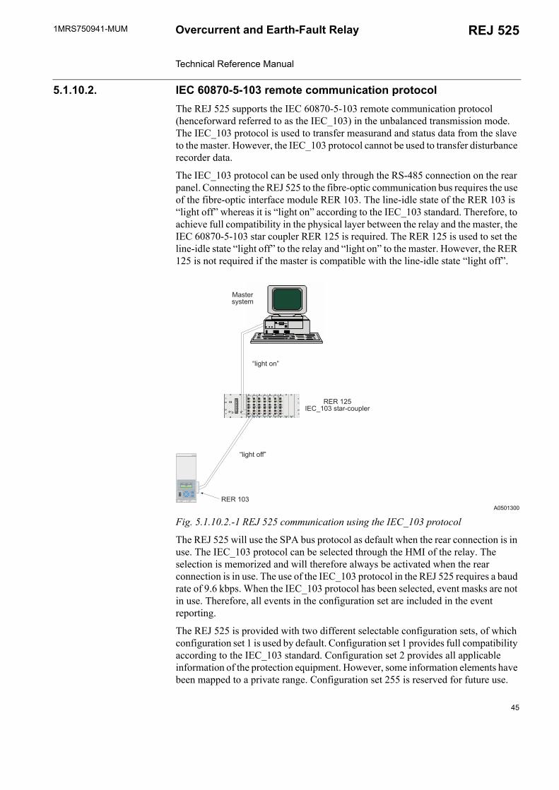
The D9S-type RS-485 connector is used to connect the relay to the distribution automation system. This connection enables the use of either the SPA bus communication protocol or the IEC 60870-5-103 communication protocol. The fibre-optic interface module RER 103 is used to connect the relay to the fibre-optic communication bus.
Although the RER 103 supports LON bus communication, the REJ 525 does not support the LON protocol. LON communication requires a separate LSG device.
A0501299
Fig. 5.1.10.1.-1 Front connector (1) for local communication
The relay is connected to a PC used for setting via the optical PC-connector on the front panel. The front interface uses the SPA bus protocol.
The optical PC-connector galvanically isolates the PC from the relay. The connection consists of a transmitter stage and a receiver stage. The front connector is standardized for ABB relay products and requires a specific opto-cable (ABB art. no 1MKC950001-2). The cable is connected to the serial RS-232C port of the PC. The optical stage of the cable is powered by RS-232C control signals.
The following serial communication parameters are to be used for RS-232C:
Relay data such as events, setting values and all input data and memorized values can be read via the optical PC-interface.
When setting values are altered via the optical PC-interface, the relay will check that the entered parameter values are within the permitted setting range. If an entered value is too high or too low, the setting value will remain unchanged.
The REJ 525 has an counter which can be accessed via COMMUNICATION under CONFIGURATION in the HMI menu. The counter value is set to 0 when the relay receives a valid message.
Number of data bits 7 Number of stop bits 1 Parity even Baud rate 9.6 kbps as default
7E
%%
44
1MRS750941-MUM REJ 525Overcurrent and Earth-Fault Relay Technical Reference Manual
5.1.10.2. IEC 60870-5-103 remote communication protocolThe REJ 525 supports the IEC 60870-5-103 remote communication protocol (henceforward referred to as the IEC_103) in the unbalanced transmission mode. The IEC_103 protocol is used to transfer measurand and status data from the slave to the master. However, the IEC_103 protocol cannot be used to transfer disturbance recorder data.
The IEC_103 protocol can be used only through the RS-485 connection on the rear panel. Connecting the REJ 525 to the fibre-optic communication bus requires the use of the fibre-optic interface module RER 103. The line-idle state of the RER 103 is light off whereas it is light on according to the IEC_103 standard. Therefore, to achieve full compatibility in the physical layer between the relay and the master, the IEC 60870-5-103 star coupler RER 125 is required. The RER 125 is used to set the line-idle state light off to the relay and light on to the master. However, the RER 125 is not required if the master is compatible with the line-idle state light off.
A0501300
Fig. 5.1.10.2.-1 REJ 525 communication using the IEC_103 protocol
The REJ 525 will use the SPA bus protocol as default when the rear connection is in use. The IEC_103 protocol can be selected through the HMI of the relay. The selection is memorized and will therefore always be activated when the rear connection is in use. The use of the IEC_103 protocol in the REJ 525 requires a baud rate of 9.6 kbps. When the IEC_103 protocol has been selected, event masks are not in use. Therefore, all events in the configuration set are included in the event reporting.
The REJ 525 is provided with two different selectable configuration sets, of which configuration set 1 is used by default. Configuration set 1 provides full compatibility according to the IEC_103 standard. Configuration set 2 provides all applicable information of the protection equipment. However, some information elements have been mapped to a private range. Configuration set 255 is reserved for future use.
5+01565+0A
I.,4?+ /J
I.,4?+ 22J
K5+1- *.01
! "##$!
%$&' ()*$ %$&' ()* +, ( -.
, ( /0
7E
%%
45
1MRS750941-MUMOvercurrent and Earth-Fault Relay Technical Reference Manual
REJ 525
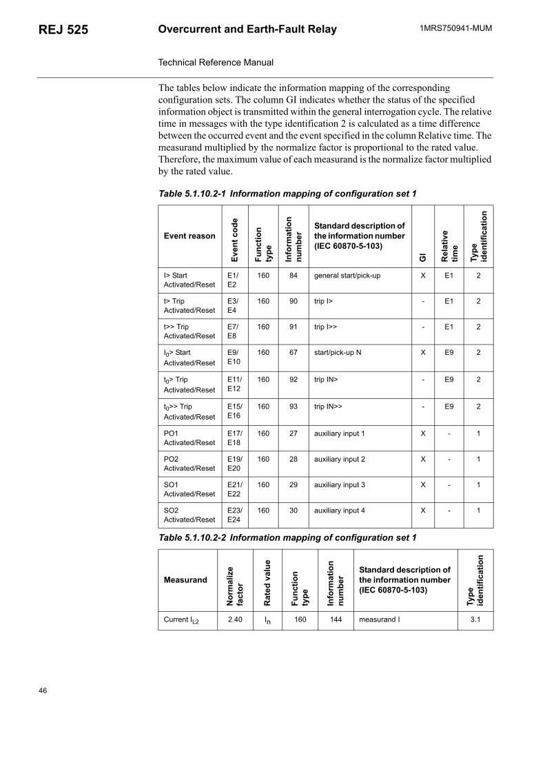
The tables below indicate the information mapping of the corresponding configuration sets. The column GI indicates whether the status of the specified information object is transmitted within the general interrogation cycle. The relative time in messages with the type identification 2 is calculated as a time difference between the occurred event and the event specified in the column Relative time. The measurand multiplied by the normalize factor is proportional to the rated value. Therefore, the maximum value of each measurand is the normalize factor multiplied by the rated value.
Table 5.1.10.2-1 Information mapping of configuration set 1
Event reasonEv
ent c
ode
Func
tion
type
Info
rmat
ion
num
ber
Standard description of the information number (IEC 60870-5-103)
GI
Rel
ativ
e tim
e
Type
id
entif
icat
ion
I> Start Activated/Reset
E1/E2
160 84 general start/pick-up X E1 2
t> Trip Activated/Reset
E3/E4
160 90 trip I> - E1 2
t>> Trip Activated/Reset
E7/E8
160 91 trip I>> - E1 2
I0> Start Activated/Reset
E9/E10
160 67 start/pick-up N X E9 2
t0> Trip Activated/Reset
E11/E12
160 92 trip IN> - E9 2
t0>> Trip Activated/Reset
E15/E16
160 93 trip IN>> - E9 2
PO1 Activated/Reset
E17/E18
160 27 auxiliary input 1 X - 1
PO2 Activated/Reset
E19/E20
160 28 auxiliary input 2 X - 1
SO1 Activated/Reset
E21/E22
160 29 auxiliary input 3 X - 1
SO2 Activated/Reset
E23/E24
160 30 auxiliary input 4 X - 1
Table 5.1.10.2-2 Information mapping of configuration set 1
Measurand
Nor
mal
ize
fact
or
Rat
ed v
alue
Func
tion
type
Info
rmat
ion
num
ber
Standard description of the information number (IEC 60870-5-103)
Type
id
entif
icat
ion
Current IL2 2.40 In 160 144 measurand I 3.1
46
1MRS750941-MUM REJ 525Overcurrent and Earth-Fault Relay Technical Reference Manual
Table 5.1.10.2-3 Information mapping of configuration set 2
Event reason
Even
t cod
e
Func
tion
type
Info
rmat
ion
num
ber
Standard description of the information number (IEC 80870-5-103)
GI
Rel
ativ
e tim
e
Type
id
entif
icat
ion
I> Start Activated/Reset
E1/E2
160 84 general start/pick-up X E1 2
t> Trip Activated/Reset
E3/E4
160 90 trip I> - E1 2
I>> Start Activated/Reset
E5/E6
162 94 - X E5 2
t>> Trip Activated/Reset
E7/E8
160 91 trip I>> - E5 2
I0> Start Activated/Reset
E9/E10
160 67 start/pick-up N X E9 2
t0> Trip Activated/Reset
E11/E12
160 92 trip IN> - E9 2
I0>> Start Activated/Reset
E13/E14
162 95 - X E13 2
t0>> Trip Activated/Reset
E15/E16
160 93 trip IN>> - E13 2
PO1 Activated/Reset
E17/E18
160 27 auxiliary input 1 X - 1
PO2 Activated/Reset
E19/E20
160 28 auxiliary input 2 X - 1
SO1 Activated/Reset
E21/E22
160 29 auxiliary input 3 X - 1
SO2 Activated/Reset
E23/E24
160 30 auxiliary input 4 X - 1
Disturbance recorder triggered
E31 162 100 - - - 1
HMI Password Opened/Closed
E32/E33
162 101 - - - 1
∆I> Start Activated/Reset
E41/E42
173 84 general start/pick-up X E41 2
t∆> Trip Activated/Reset
E43/E44
173 90 trip I> - E41 2
47
1MRS750941-MUMOvercurrent and Earth-Fault Relay Technical Reference Manual
REJ 525
5.1.10.3. Event codesSpecial codes have been determined to represent certain events, such as start and tripping of protection stages and different states of output signals.
Events E1...E51 are stored in the event register of the relay. The maximum capacity of the register is 60 events. Under normal conditions the register is empty.
The contents of the register can be read using the L command, five events at a time. Using the L command erases the previously read events from the register, with the exception of events E50 and E51 which have to be reset using the C command. Should a fault occur, for example in data communication, these events can be re-read using the B command. If needed, the B command can also be repeated.
Events to be included in the event reporting are marked with multiplier 1. The event mask is formed by the sum of the weighting factors of all those events which are to be included in the event reporting.
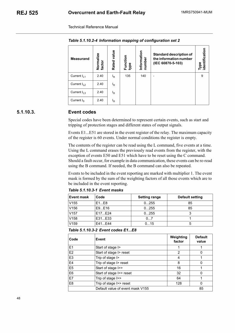
Table 5.1.10.2-4 Information mapping of configuration set 2
Measurand
Nor
mal
ize
fact
or
Rat
ed v
alue
Func
tion
type
Info
rmat
ion
num
ber
Standard description of the information number (IEC 60870-5-103)
Type
id
entif
icat
ion
Current IL1 2.40 In 135 140 - 9
Current IL2 2.40 In
Current IL3 2.40 In
Current I0 2.40 In
Table 5.1.10.3-1 Event masks
Event mask Code Setting range Default settingV155 E1...E8 0...255 85V156 E9...E16 0...255 85V157 E17...E24 0...255 3V158 E31...E33 0...7 1V159 E41...E44 0...15 5
Table 5.1.10.3-2 Event codes E1...E8
Code Event Weighting factor
Default value
E1 Start of stage I> 1 1E2 Start of stage I> reset 2 0E3 Trip of stage I> 4 1E4 Trip of stage I> reset 8 0E5 Start of stage I>> 16 1E6 Start of stage I>> reset 32 0E7 Trip of stage I>> 64 1E8 Trip of stage I>> reset 128 0
Default value of event mask V155 85
48
1MRS750941-MUM REJ 525Overcurrent and Earth-Fault Relay Technical Reference Manual
Explanations of the default values:
0 = not included in the event reporting1 = included in the event reporting
Events E50 and E51 are always included in the event reporting.
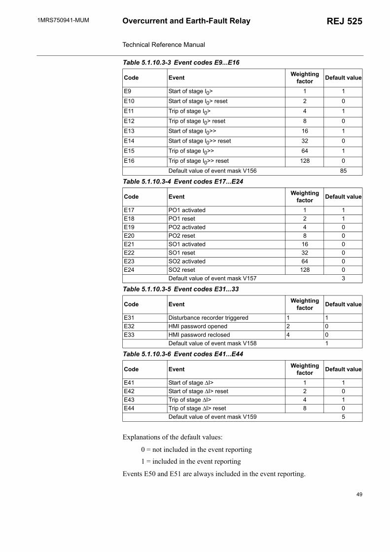
Table 5.1.10.3-3 Event codes E9...E16
Code Event Weighting factor Default value
E9 Start of stage I0> 1 1
E10 Start of stage I0> reset 2 0
E11 Trip of stage I0> 4 1
E12 Trip of stage I0> reset 8 0
E13 Start of stage I0>> 16 1
E14 Start of stage I0>> reset 32 0
E15 Trip of stage I0>> 64 1
E16 Trip of stage I0>> reset 128 0
Default value of event mask V156 85
Table 5.1.10.3-4 Event codes E17...E24
Code Event Weighting factor Default value
E17 PO1 activated 1 1E18 PO1 reset 2 1E19 PO2 activated 4 0E20 PO2 reset 8 0E21 SO1 activated 16 0E22 SO1 reset 32 0E23 SO2 activated 64 0E24 SO2 reset 128 0
Default value of event mask V157 3
Table 5.1.10.3-5 Event codes E31...33
Code Event Weighting factor Default value
E31 Disturbance recorder triggered 1 1E32 HMI password opened 2 0E33 HMI password reclosed 4 0
Default value of event mask V158 1
Table 5.1.10.3-6 Event codes E41...E44
Code Event Weighting factor Default value
E41 Start of stage ∆I> 1 1E42 Start of stage ∆I> reset 2 0E43 Trip of stage ∆I> 4 1E44 Trip of stage ∆I> reset 8 0
Default value of event mask V159 5
49
1MRS750941-MUMOvercurrent and Earth-Fault Relay Technical Reference Manual
REJ 525
5.1.10.4. SPA bus communication protocol parametersIn some cases, altering parameter values via serial communication requires the use of the SPA password. The password is a number within the range 1...999, the default value being 1.
To enter the setting mode, enter the password into parameter V160. To quit the setting mode, enter the same password into parameter V161. The password protection is also reactivated in case of loss of auxiliary voltage.
The HMI password can be changed via parameter V162, but it is not possible to read the password via this parameter.
Abbreviations used in the following tables:
R = readable data W = writeable data P = password protected writeable data I = input data S = setting value V = recorded data/parameter M = disturbance recorder parameter O = output data
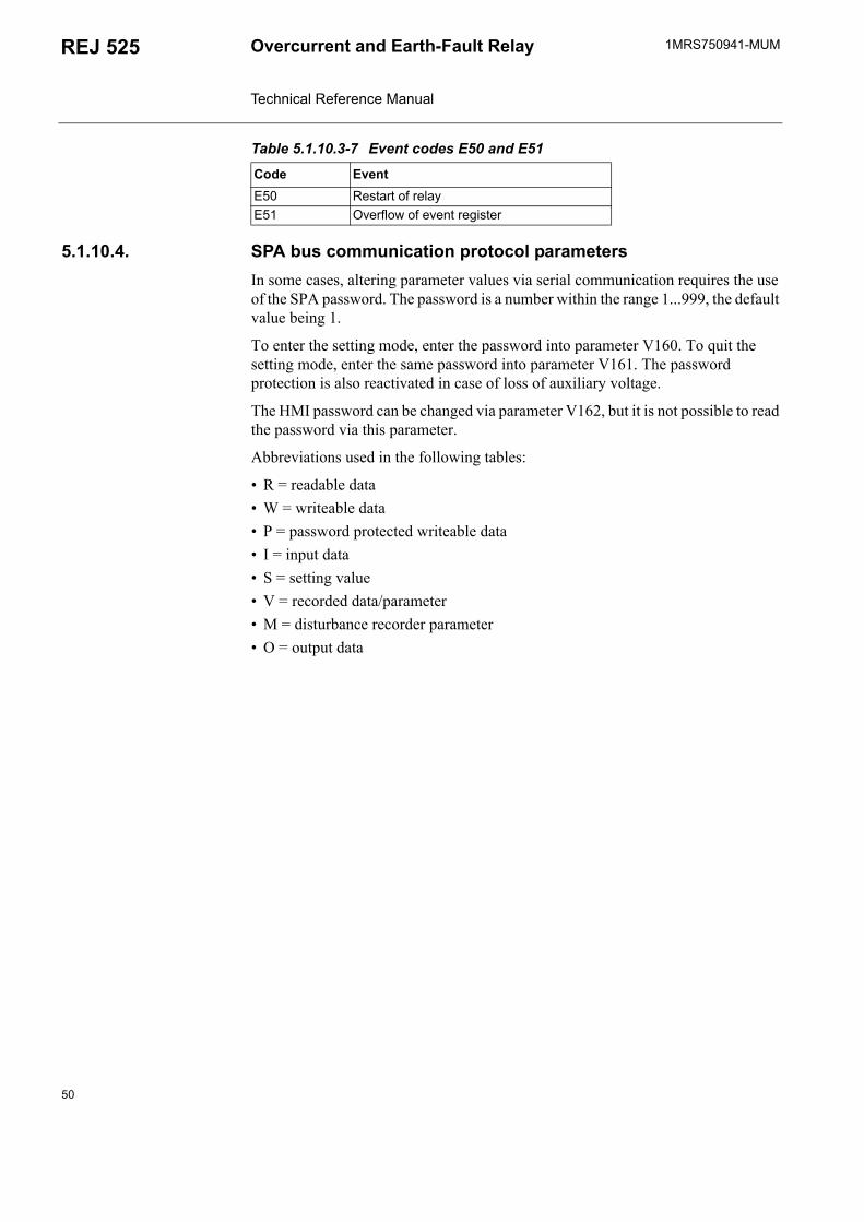
Table 5.1.10.3-7 Event codes E50 and E51
Code EventE50 Restart of relayE51 Overflow of event register
50
1MRS750941-MUM REJ 525Overcurrent and Earth-Fault Relay Technical Reference Manual
Settings
1) Values above 1 equal 1.2) If the protection stage has been set out of operation, the number indicating the currently used value
will be displaced by 999 when parameters are read via the SPA bus and by dashes on the LCD.
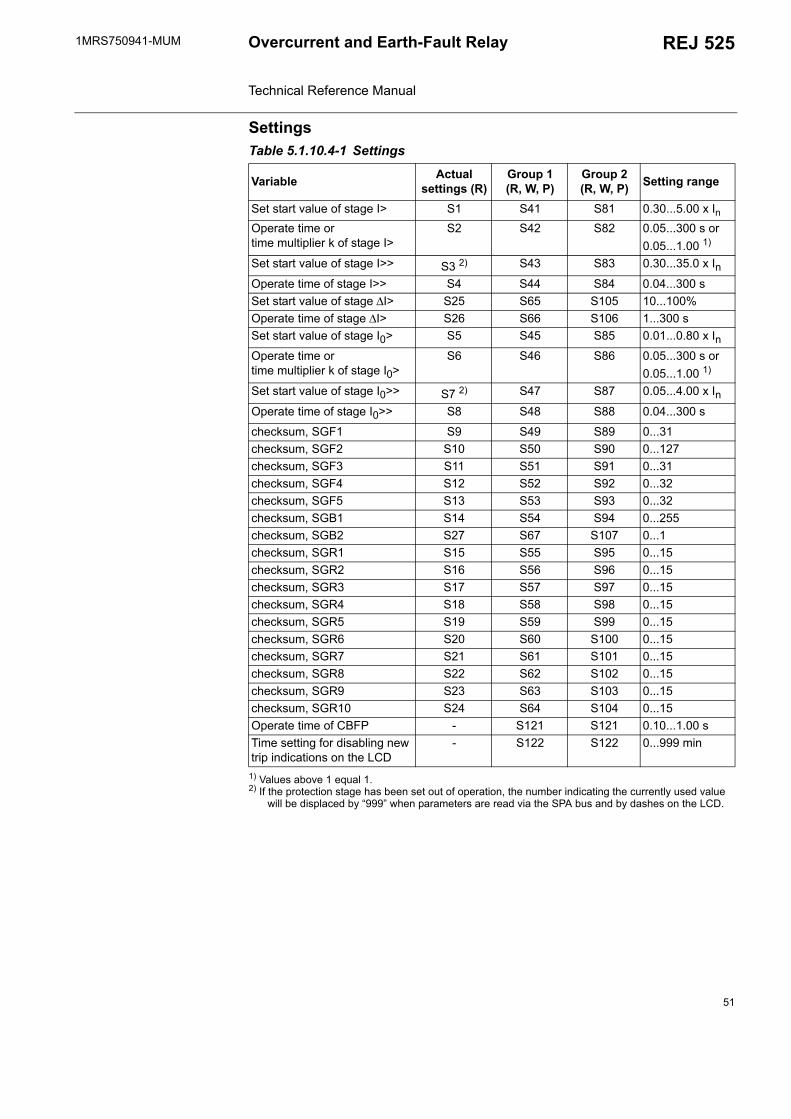
Table 5.1.10.4-1 Settings
Variable Actual settings (R)
Group 1 (R, W, P)
Group 2 (R, W, P) Setting range
Set start value of stage I> S1 S41 S81 0.30...5.00 x InOperate time or time multiplier k of stage I>
S2 S42 S82 0.05...300 s or 0.05...1.00 1)
Set start value of stage I>> S3 2) S43 S83 0.30...35.0 x InOperate time of stage I>> S4 S44 S84 0.04...300 sSet start value of stage ∆I> S25 S65 S105 10...100%Operate time of stage ∆I> S26 S66 S106 1...300 sSet start value of stage I0> S5 S45 S85 0.01...0.80 x InOperate time or time multiplier k of stage I0>
S6 S46 S86 0.05...300 s or 0.05...1.00 1)
Set start value of stage I0>> S7 2) S47 S87 0.05...4.00 x InOperate time of stage I0>> S8 S48 S88 0.04...300 s
checksum, SGF1 S9 S49 S89 0...31checksum, SGF2 S10 S50 S90 0...127checksum, SGF3 S11 S51 S91 0...31checksum, SGF4 S12 S52 S92 0...32checksum, SGF5 S13 S53 S93 0...32checksum, SGB1 S14 S54 S94 0...255checksum, SGB2 S27 S67 S107 0...1checksum, SGR1 S15 S55 S95 0...15checksum, SGR2 S16 S56 S96 0...15checksum, SGR3 S17 S57 S97 0...15checksum, SGR4 S18 S58 S98 0...15checksum, SGR5 S19 S59 S99 0...15checksum, SGR6 S20 S60 S100 0...15checksum, SGR7 S21 S61 S101 0...15checksum, SGR8 S22 S62 S102 0...15checksum, SGR9 S23 S63 S103 0...15checksum, SGR10 S24 S64 S104 0...15Operate time of CBFP - S121 S121 0.10...1.00 sTime setting for disabling new trip indications on the LCD
- S122 S122 0...999 min
51
1MRS750941-MUMOvercurrent and Earth-Fault Relay Technical Reference Manual
REJ 525
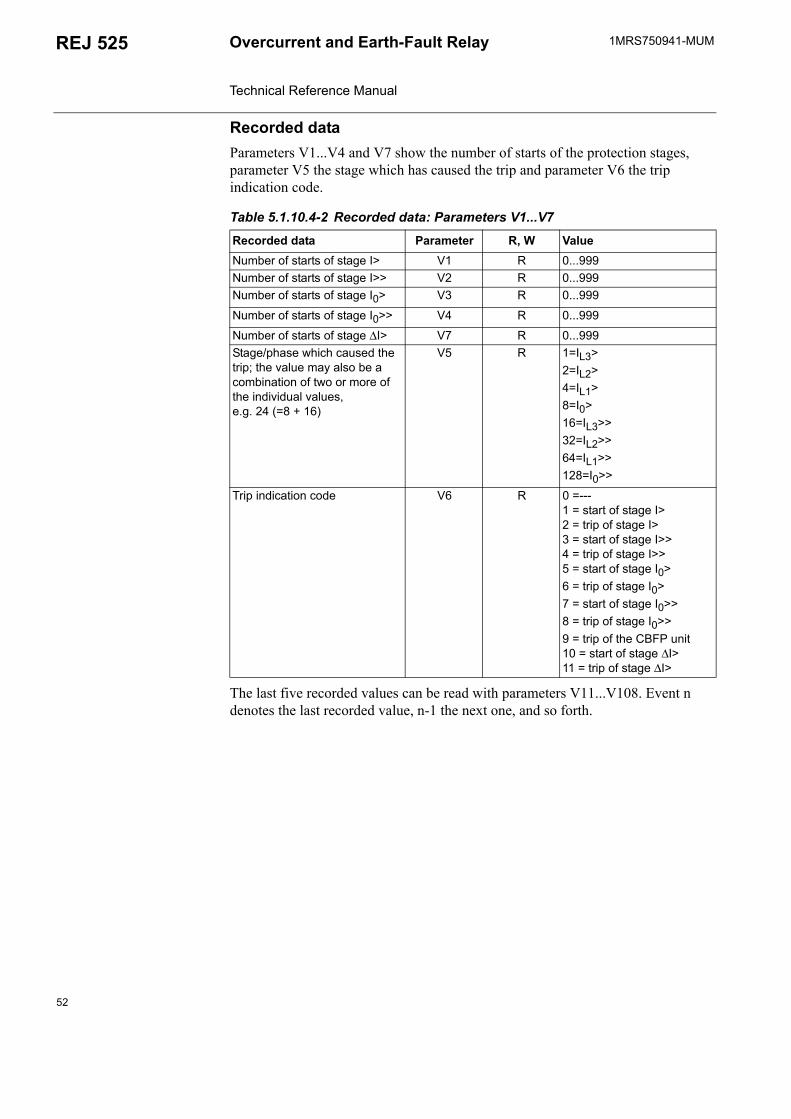
Recorded dataParameters V1...V4 and V7 show the number of starts of the protection stages, parameter V5 the stage which has caused the trip and parameter V6 the trip indication code.
The last five recorded values can be read with parameters V11...V108. Event n denotes the last recorded value, n-1 the next one, and so forth.
Table 5.1.10.4-2 Recorded data: Parameters V1...V7
Recorded data Parameter R, W ValueNumber of starts of stage I> V1 R 0...999Number of starts of stage I>> V2 R 0...999Number of starts of stage I0> V3 R 0...999
Number of starts of stage I0>> V4 R 0...999
Number of starts of stage ∆I> V7 R 0...999Stage/phase which caused the trip; the value may also be a combination of two or more of the individual values, e.g. 24 (=8 + 16)
V5 R 1=IL3> 2=IL2>4=IL1>8=I0>16=IL3>> 32=IL2>>64=IL1>>128=I0>>
Trip indication code V6 R 0 =---1 = start of stage I>2 = trip of stage I>3 = start of stage I>>4 = trip of stage I>>5 = start of stage I0>6 = trip of stage I0>7 = start of stage I0>>8 = trip of stage I0>>9 = trip of the CBFP unit10 = start of stage ∆I>11 = trip of stage ∆I>
52
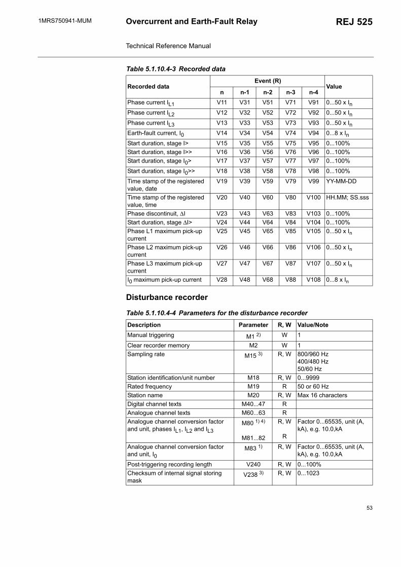
1MRS750941-MUM REJ 525Overcurrent and Earth-Fault Relay Technical Reference Manual
Disturbance recorder
Table 5.1.10.4-3 Recorded data
Recorded dataEvent (R)
Valuen n-1 n-2 n-3 n-4
Phase current IL1 V11 V31 V51 V71 V91 0...50 x InPhase current IL2 V12 V32 V52 V72 V92 0...50 x InPhase current IL3 V13 V33 V53 V73 V93 0...50 x InEarth-fault current, I0 V14 V34 V54 V74 V94 0...8 x InStart duration, stage I> V15 V35 V55 V75 V95 0...100%Start duration, stage I>> V16 V36 V56 V76 V96 0...100%Start duration, stage I0> V17 V37 V57 V77 V97 0...100%
Start duration, stage I0>> V18 V38 V58 V78 V98 0...100%
Time stamp of the registered value, date
V19 V39 V59 V79 V99 YY-MM-DD
Time stamp of the registered value, time
V20 V40 V60 V80 V100 HH.MM; SS.sss
Phase discontinuit, ∆I V23 V43 V63 V83 V103 0...100%Start duration, stage ∆I> V24 V44 V64 V84 V104 0...100%Phase L1 maximum pick-up current
V25 V45 V65 V85 V105 0...50 x In
Phase L2 maximum pick-up current
V26 V46 V66 V86 V106 0...50 x In
Phase L3 maximum pick-up current
V27 V47 V67 V87 V107 0...50 x In
I0 maximum pick-up current V28 V48 V68 V88 V108 0...8 x In
Table 5.1.10.4-4 Parameters for the disturbance recorder
Description Parameter R, W Value/NoteManual triggering M1 2) W 1
Clear recorder memory M2 W 1Sampling rate M15 3) R, W 800/960 Hz
400/480 Hz50/60 Hz
Station identification/unit number M18 R, W 0...9999Rated frequency M19 R 50 or 60 HzStation name M20 R, W Max 16 charactersDigital channel texts M40...47 RAnalogue channel texts M60...63 RAnalogue channel conversion factor and unit, phases IL1, IL2 and IL3
M80 1) 4)
M81...82
R, W
R
Factor 0...65535, unit (A, kA), e.g. 10.0,kA
Analogue channel conversion factor and unit, I0
M83 1) R, W Factor 0...65535, unit (A, kA), e.g. 10.0,kA
Post-triggering recording length V240 R, W 0...100%Checksum of internal signal storing mask
V238 3) R, W 0...1023
53
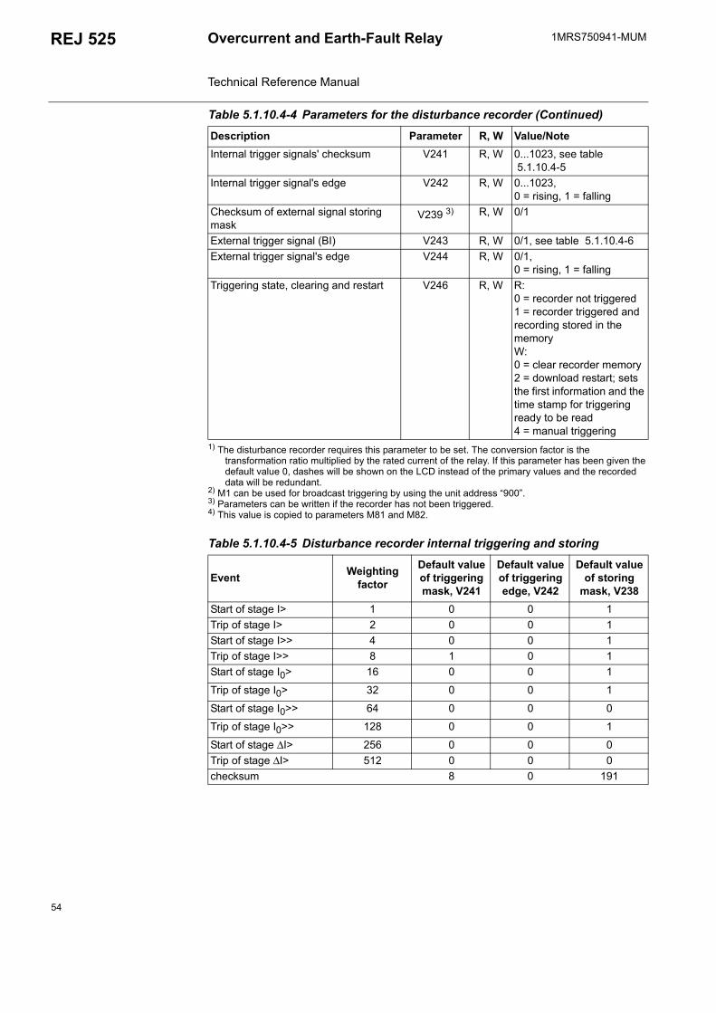
1MRS750941-MUMOvercurrent and Earth-Fault Relay Technical Reference Manual
REJ 525
1) The disturbance recorder requires this parameter to be set. The conversion factor is the transformation ratio multiplied by the rated current of the relay. If this parameter has been given the default value 0, dashes will be shown on the LCD instead of the primary values and the recorded data will be redundant.
2) M1 can be used for broadcast triggering by using the unit address 900.3) Parameters can be written if the recorder has not been triggered.4) This value is copied to parameters M81 and M82.
Internal trigger signals' checksum V241 R, W 0...1023, see table 5.1.10.4-5
Internal trigger signal's edge V242 R, W 0...1023, 0 = rising, 1 = falling
Checksum of external signal storing mask
V239 3) R, W 0/1
External trigger signal (BI) V243 R, W 0/1, see table 5.1.10.4-6External trigger signal's edge V244 R, W 0/1,
0 = rising, 1 = fallingTriggering state, clearing and restart V246 R, W R:
0 = recorder not triggered1 = recorder triggered and recording stored in the memoryW:0 = clear recorder memory2 = download restart; sets the first information and the time stamp for triggering ready to be read4 = manual triggering
Table 5.1.10.4-5 Disturbance recorder internal triggering and storing
Event Weighting factor
Default value of triggering mask, V241
Default value of triggering edge, V242
Default value of storing
mask, V238Start of stage I> 1 0 0 1Trip of stage I> 2 0 0 1Start of stage I>> 4 0 0 1Trip of stage I>> 8 1 0 1Start of stage I0> 16 0 0 1
Trip of stage I0> 32 0 0 1
Start of stage I0>> 64 0 0 0
Trip of stage I0>> 128 0 0 1
Start of stage ∆I> 256 0 0 0Trip of stage ∆I> 512 0 0 0checksum 8 0 191
Table 5.1.10.4-4 Parameters for the disturbance recorder (Continued)
Description Parameter R, W Value/Note
54
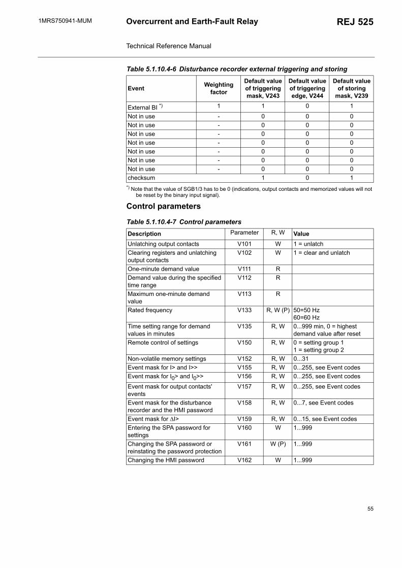
1MRS750941-MUM REJ 525Overcurrent and Earth-Fault Relay Technical Reference Manual
*) Note that the value of SGB1/3 has to be 0 (indications, output contacts and memorized values will not be reset by the binary input signal).
Control parameters
Table 5.1.10.4-6 Disturbance recorder external triggering and storing
Event Weighting factor
Default value of triggering mask, V243
Default value of triggering edge, V244
Default value of storing
mask, V239
External BI *) 1 1 0 1
Not in use - 0 0 0Not in use - 0 0 0Not in use - 0 0 0Not in use - 0 0 0Not in use - 0 0 0Not in use - 0 0 0Not in use - 0 0 0checksum 1 0 1
Table 5.1.10.4-7 Control parameters
Description Parameter R, W ValueUnlatching output contacts V101 W 1 = unlatchClearing registers and unlatching output contacts
V102 W 1 = clear and unlatch
One-minute demand value V111 RDemand value during the specified time range
V112 R
Maximum one-minute demand value
V113 R
Rated frequency V133 R, W (P) 50=50 Hz60=60 Hz
Time setting range for demand values in minutes
V135 R, W 0...999 min, 0 = highest demand value after reset
Remote control of settings V150 R, W 0 = setting group 11 = setting group 2
Non-volatile memory settings V152 R, W 0...31Event mask for I> and I>> V155 R, W 0...255, see Event codesEvent mask for I0> and I0>> V156 R, W 0...255, see Event codes
Event mask for output contacts' events
V157 R, W 0...255, see Event codes
Event mask for the disturbance recorder and the HMI password
V158 R, W 0...7, see Event codes
Event mask for ∆I> V159 R, W 0...15, see Event codesEntering the SPA password for settings
V160 W 1...999
Changing the SPA password or reinstating the password protection
V161 W (P) 1...999
Changing the HMI password V162 W 1...999
55
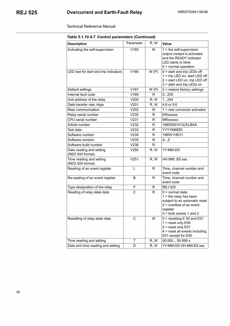
1MRS750941-MUMOvercurrent and Earth-Fault Relay Technical Reference Manual
REJ 525
Activating the self-supervision V165 W 1 = the self-supervision output contact is activated and the READY indicator LED starts to blink0 = normal operation
LED test for start and trip indicators V166 W (P) 0 = start and trip LEDs off1 = trip LED on, start LED off2 = start LED on, trip LED off3 = start and trip LEDs on
Default settings V167 W (P) 2 = restore factory settingsInternal fault code V169 R 0...255Unit address of the relay V200 R, W 1...254Data transfer rate, kbps V201 R, W 4.8 or 9.6Rear communication V202 W 1 = rear connector activatedRelay serial number V230 R ERxxxxxxCPU serial number V231 R MRxxxxxxArticle number V232 R 1MRS091412(/5)-BAATest date V233 R YYYYMMDDSoftware number V234 R 1MRS118011Software revision V235 R A...ZSoftware build number V236 RDate reading and setting (RED 500 format)
V250 R, W YY-MM-DD
Time reading and setting (RED 500 format)
V251 R, W HH.MM; SS.sss
Reading of an event register L R Time, channel number and event code
Re-reading of an event register B R Time, channel number and event code
Type designation of the relay F R REJ 525Reading of relay state data C R 0 = normal state
1 = the relay has been subject to an automatic reset2 = overflow of an event register3 = both events 1 and 2
Resetting of relay state data C W 0 = resetting E 50 and E511 = reset only E502 = reset only E514 = reset all events including E51 except for E50
Time reading and setting T R, W 00.000... 59.999 sDate and time reading and setting D R, W YY-MM-DD HH.MM;SS.sss
Table 5.1.10.4-7 Control parameters (Continued)
Description Parameter R, W Value
56
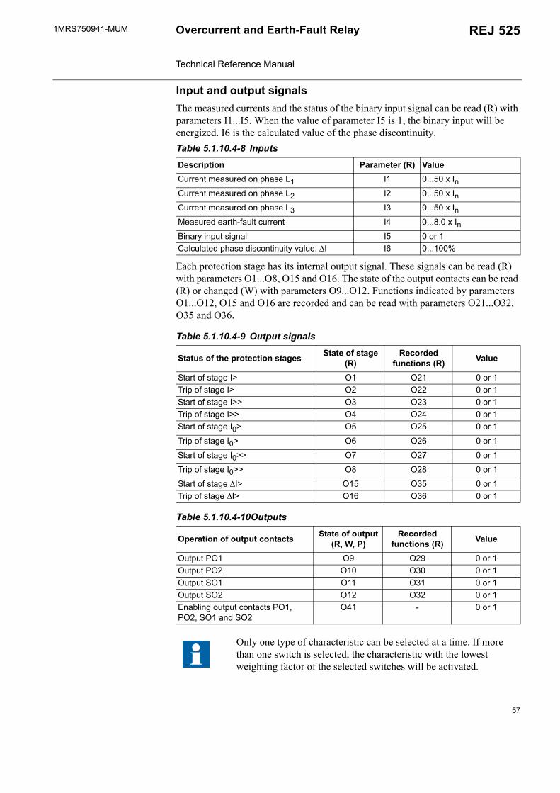
1MRS750941-MUM REJ 525Overcurrent and Earth-Fault Relay Technical Reference Manual
Input and output signalsThe measured currents and the status of the binary input signal can be read (R) with parameters I1...I5. When the value of parameter I5 is 1, the binary input will be energized. I6 is the calculated value of the phase discontinuity.
Each protection stage has its internal output signal. These signals can be read (R) with parameters O1...O8, O15 and O16. The state of the output contacts can be read (R) or changed (W) with parameters O9...O12. Functions indicated by parameters O1...O12, O15 and O16 are recorded and can be read with parameters O21...O32, O35 and O36.
Table 5.1.10.4-8 Inputs
Description Parameter (R) ValueCurrent measured on phase L1 I1 0...50 x InCurrent measured on phase L2 I2 0...50 x InCurrent measured on phase L3 I3 0...50 x InMeasured earth-fault current I4 0...8.0 x InBinary input signal I5 0 or 1Calculated phase discontinuity value, ∆I I6 0...100%
Table 5.1.10.4-9 Output signals
Status of the protection stages State of stage (R)
Recorded functions (R) Value
Start of stage I> O1 O21 0 or 1Trip of stage I> O2 O22 0 or 1Start of stage I>> O3 O23 0 or 1Trip of stage I>> O4 O24 0 or 1Start of stage I0> O5 O25 0 or 1
Trip of stage I0> O6 O26 0 or 1
Start of stage I0>> O7 O27 0 or 1
Trip of stage I0>> O8 O28 0 or 1
Start of stage ∆I> O15 O35 0 or 1Trip of stage ∆I> O16 O36 0 or 1
Table 5.1.10.4-10Outputs
Operation of output contacts State of output (R, W, P)
Recorded functions (R) Value
Output PO1 O9 O29 0 or 1Output PO2 O10 O30 0 or 1Output SO1 O11 O31 0 or 1Output SO2 O12 O32 0 or 1Enabling output contacts PO1, PO2, SO1 and SO2
O41 - 0 or 1
Only one type of characteristic can be selected at a time. If more than one switch is selected, the characteristic with the lowest weighting factor of the selected switches will be activated.
57
1MRS750941-MUMOvercurrent and Earth-Fault Relay Technical Reference Manual
REJ 525
5.1.11. Self-supervision (IRF) system The REJ 525 is provided with an extensive self-supervision system which continuously supervises the software and the electronics of the relay. It handlesrun-time fault situations and informs the user about an existing fault via a LED on the HMI and a text message on the LCD.
When a fault is detected, the relay will first try to eliminate it by restarting. Only after the fault has been found to be permanent, the green READY indicator LED will start to blink and the self-supervision output contact will be activated. All other output contacts are blocked during an internal fault. Further, a fault indication message will appear on the LCD.
Fault indications have the highest priority on the HMI. None of the other HMI indications can override the IRF indication. As long as the READY indicator LED is blinking, the fault indication can not be cleared. In case an internal fault disappears, the READY indicator LED will stop blinking and the IRF relay will be returned to the normal service state, but the fault indication message will remain on the LCD.
The IRF code is the code of the last internal fault detected by the self-supervision system and describes the type of fault. When a fault appears, the code is to be recorded and given to an authorised repair shop when overhaul is ordered. For fault codes, refer to the Operators Manual.
5.1.12. Relay parameterizationLocal parameterizationThe parameters of the relay can be set either locally via the HMI or externally via serial communication with the Relay Setting Tool. When the parameters are set locally, the setting parameters can be chosen via the hierarchical menu structure. The desired language can be selected for parameter descriptions. Refer to the Operators Manual for further information.
External parameterizationThe Relay Setting Tool is used for parameterizing the relay units. Adjusting the parameter values using the Relay Setting Tool is done off-line, after which the parameters can be downloaded to the relay via a communication port.
5.2. Design description
5.2.1. Input/output connectionsAll external circuits are connected to the terminals on the rear panel of the relay. Terminals X1.1-_ are dimensioned for one 0.5...6.0 mm2 wire or for two max 2.5 mm2 wires and terminals X2.1-_ for one 0.08...2.5 mm2 wire or for two max 1.5 mm2 wires.
58
1MRS750941-MUM REJ 525Overcurrent and Earth-Fault Relay Technical Reference Manual
The energizing currents of the overcurrent unit are connected to terminals X1.1/4-5, X1.1/7-8 and X1.1/10-11 when the rated current of the CT secondary circuits is In = 5 A and to terminals X1.1/4-6, X1.1/7-9 and X1.1/10-12 when it is In = 1 A. The relay can also be used in single or two-phase applications by leaving one or two energizing inputs unoccupied.
The energizing current of the earth-fault unit is connected to terminals X1.1/1-3 (see table 5.2.1-1.
The binary input X2.1/17-18 can be used to generate an external blocking signal, to unlatch the output contacts or for remote control of relay settings. The requested function is selected in SGB. The binary input can also be used as a trigger signal for the disturbance recorder; this function is selected with SPA parameter V243.
The auxiliary voltage of the relay is connected to terminals X2.1/1-2. At DC supply, the positive lead is connected to terminal X2.1/1. For details, refer to the description of the auxiliary voltage. The permitted auxiliary voltage range of the relay is marked on the front panel of the relay.
Output contacts PO1 and PO2 are heavy-duty trip contacts capable of controlling most circuit breakers. The trip signals from the different protection stages are routed to the output contacts with switches 1 and 2 of SGR1...SGR10. On delivery from the factory, the trip signals from all the protection stages are routed to both PO1 and PO2.
Output contacts SO1 and SO2 can be used for signalling on start and tripping of the relay. The signals to be routed to output contacts SO1 and SO2 are selected with switches 3 and 4 of SGR1...SGR10. On delivery from the factory, the start signals from all the protection stages are routed to both SO1 and SO2.
Output contact IRF functions as an output contact for the self-supervision system of the protection relay. The IRF relay is energized under normal operating conditions and contact gap X2.1/13-15 is closed. When a fault is detected by the self-supervision system or the auxiliary voltage is disconnected, the output contact will drop off and contact X2.1/13-14 will close.
The following picture presents a rear view of the REJ 525, showing three connecting sockets: one for measuring transformers, one for power supply and one for serial communication.
59
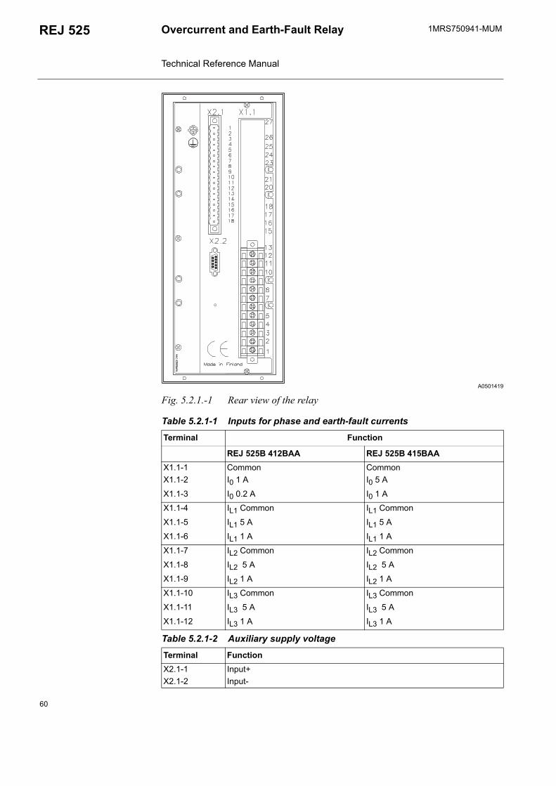
1MRS750941-MUMOvercurrent and Earth-Fault Relay Technical Reference Manual
REJ 525
A0501419
Fig. 5.2.1.-1 Rear view of the relay
Table 5.2.1-1 Inputs for phase and earth-fault currents
Terminal Function
REJ 525B 412BAA REJ 525B 415BAAX1.1-1 Common CommonX1.1-2 I0 1 A I0 5 A
X1.1-3 I0 0.2 A I0 1 A
X1.1-4 IL1 Common IL1 Common
X1.1-5 IL1 5 A IL1 5 A
X1.1-6 IL1 1 A IL1 1 A
X1.1-7 IL2 Common IL2 Common
X1.1-8 IL2 5 A IL2 5 A
X1.1-9 IL2 1 A IL2 1 A
X1.1-10 IL3 Common IL3 Common
X1.1-11 IL3 5 A IL3 5 A
X1.1-12 IL3 1 A IL3 1 A
Table 5.2.1-2 Auxiliary supply voltage
Terminal FunctionX2.1-1 Input+X2.1-2 Input-
60
1MRS750941-MUM REJ 525Overcurrent and Earth-Fault Relay Technical Reference Manual
5.2.2. Serial communication connectionsThe REJ 525 is interfaced with a fibre-optic bus by means of the bus connection module RER 103 via the D9S-type connector X2 located on the rear panel of the device. The terminals of the fibre-optic cables are connected to the counter terminals Rx (Receiver) and Tx (Transmitter) of the bus connection module. The fibre-optic cables are linked from one protection relay to another and to the substation level communication unit, e.g. SRIO 1000M and the RER 125.
The optical PC-connection on the front panel of the relay is used to connect the relay to a fibre-optic SPA bus via opto-cable 1MKC950001-2.
Table 5.2.1-3 Output contacts
Terminal FunctionX2.1-3 PO1, closing contactX2.1-4X2.1-5 PO2, closing contactX2.1-6X2.1-7 SO1, commonX2.1-8 SO1, NCX2.1-9 SO1, NOX2.1-10 SO2, commonX2.1-11 SO2, NCX2.1-12 SO2, NO
Table 5.2.1-4 IRF contact
Terminal FunctionX2.1-13 Internal relay fault, commonX2.1-14 Closed; IRF, or Uaux disconnected
X2.1-15 Closed; no IRF, and Uaux connected
Table 5.2.1-5 Binary input
Terminal FunctionX2.1-17 Input+X2.1-18 Input-
Table 5.2.2-1 RS-485 connector X2 for the RER 103
Terminal FunctionX.2.2-1 Data A (data signal +)X.2.2-2 Data B (data signal -)X.2.2-3 RTS A (request to send +)X.2.2-4 RTS B (request to send -)X.2.2-5 COL A (2.8 V on relay)X.2.2-6 COL B (2.2 V on relay)X.2.2-7 GNDX.2.2-8 NCX.2.2-9 +5 V DC, auxiliary voltage (max. 200 mA)
61
1MRS750941-MUMOvercurrent and Earth-Fault Relay Technical Reference Manual
REJ 525
5.2.3. Technical data
1) For dimension drawings, refer to the Installation Manual (1MRS 750526-MUM).
Table 5.2.3-1 Dimensions 1)
Width, frame 111.4 mm, box 94 mmHeight, frame 265.9 mm (6U), box 249.8 mmDepth 235 mm (245.1 mm with a protective rear cover, available as an option)Enclosure size 1/4 (x 19")Weight of the relay ~3.3 kg
Table 5.2.3-2 Power supplyUaux rated Ur=10/120/220/240 V AC
Ur=48/60/110/125/220 V DCUaux variation 80...265 V AC
38...265 V DCRelay power start-up time, typical 300 msBurden of auxiliary voltage supply under quiescent/operating condition
~5 W/~10 W
Ripple in the DC auxiliary voltage Max 12% of the DC valueInterruption time in the auxiliary DC voltage without resetting the relay
< 30 ms at 48 V DC< 100 ms at 110 V DC< 500 ms at 220 V DC
Table 5.2.3-3 Energizing inputsRated frequency 50/60 Hz ±5 HzRated current, In 0.2 A 1 A 5 A
Thermal withstand capability continuously 1.5 A 4 A 20 A for 1 s 20 A 100 A 500 ADynamic current withstand half-wave value 50 A 250 A 1250 AInput impedance < 750 mΩ < 100 mΩ < 20 mΩ
Table 5.2.3-4 Measuring rangeMeasured currents on phases L1, L2 and L3 as multiples of the rated currents of the energizing inputs
0...50 x In
Earth-fault current as a multiple of the rated current of the energizing input
0...8 x In
Table 5.2.3-5 Binary inputOperating range 18...265 V DCRated voltage 24/48/60/110/220 V DCCurrent drain ~ 2...25 mAPower consumption < 0.8 W
62
1MRS750941-MUM REJ 525Overcurrent and Earth-Fault Relay Technical Reference Manual
Table 5.2.3-6 Signal outputs (SO1, SO2) and self-supervision (IRF) output Rated voltage 250 V AC/DCContinuous carry 5 AMake and carry for 3.0 s 8 AMake and carry for 0.5 s 10 ABreaking capacity when the control circuit time-constant L/R < 40 ms, at 48/110/220 V DC
1 A/0.25 A/0.15 A
Minimum contact load 100 mA at 24 V AC/DC
Table 5.2.3-7 Power outputs (PO1, PO2)Rated voltage 250 V AC/DCContinuous carry 5 AMake and carry for 3.0 s 15 AMake and carry for 0.5 s 30 ABreaking capacity when the control circuit time-constant L/R < 40 ms, at 48/110/220 V DC
5 A/3 A/1 A
Minimum contact load 100 mA at 24 V AC/DC
Table 5.2.3-8 Enclosure classFront side IP 54 (flush-mounted)Rear side, connection terminals IP 20Note!A rear protective cover (accessory part) can be used to protect and shield the rear of the case.
Table 5.2.3-9 Environmental testsSpecified service temperature range -10...+55 °CTransport and storage temperature range -40...+70 °C according to
the IEC 60068-2-48Dry heat test According to the IEC 60068-2-2Dry cold test According to the IEC 60068-2-1 Damp heat test, cyclic According to the IEC 60068-2-30
Table 5.2.3-10 Electromagnetic compatibility testsEMC immunity test level requirements consider the demands in the generic standard EN 50082-2.1 MHz burst disturbance test, class III According to the IEC 60255-22-1 Common mode 2.5 kV Differential mode 1.0 kVElectrostatic discharge test, class III According to the IEC 61000-4-2 and
IEC 60255-22-2 For contact discharge 6 kV For air discharge 8 kV
63
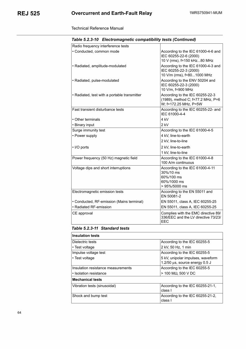
1MRS750941-MUMOvercurrent and Earth-Fault Relay Technical Reference Manual
REJ 525
Radio frequency interference tests Conducted, common mode According to the IEC 61000-4-6 and
IEC 60255-22-6 (2000)10 V (rms), f=150 kHz...80 MHz
Radiated, amplitude-modulated According to the IEC 61000-4-3 andIEC 60255-22-3 (2000)10 V/m (rms), f=80...1000 MHz
Radiated, pulse-modulated According to the ENV 50204 andIEC 60255-22-3 (2000)10 V/m, f=900 MHz
Radiated, test with a portable transmitter According to the IEC 60255-22-3 (1989), method C; f=77.2 MHz, P=6 W; f=172.25 MHz, P=5W
Fast transient disturbance tests According to the IEC 60255-22- and IEC 61000-4-4
Other terminals 4 kV Binary input 2 kVSurge immunity test According to the IEC 61000-4-5 Power supply 4 kV, line-to-earth
2 kV, line-to-line
I/O ports 2 kV, line-to-earth1 kV, line-to-line
Power frequency (50 Hz) magnetic field According to the IEC 61000-4-8100 A/m continuous
Voltage dips and short interruptions According to the IEC 61000-4-1130%/10 ms60%/100 ms60%/1000 ms> 95%/5000 ms
Electromagnetic emission tests According to the EN 55011 and EN 50081-2
Conducted, RF-emission (Mains terminal) EN 55011, class A, IEC 60255-25 Radiated RF-emission EN 55011, class A, IEC 60255-25
CE approval Complies with the EMC directive 89/336/EEC and the LV directive 73/23/EEC
Table 5.2.3-11 Standard tests
Insulation testsDielectric tests According to the IEC 60255-5 Test voltage 2 kV, 50 Hz, 1 minImpulse voltage test According to the IEC 60255-5 Test voltage 5 kV, unipolar impulses, waveform
1.2/50 µs, source energy 0.5 JInsulation resistance measurements According to the IEC 60255-5 Isolation resistance > 100 MΩ, 500 V DC
Mechanical testsVibration tests (sinusoidal) According to the IEC 60255-21-1,
class IShock and bump test According to the IEC 60255-21-2,
class I
Table 5.2.3-10 Electromagnetic compatibility tests (Continued)
64
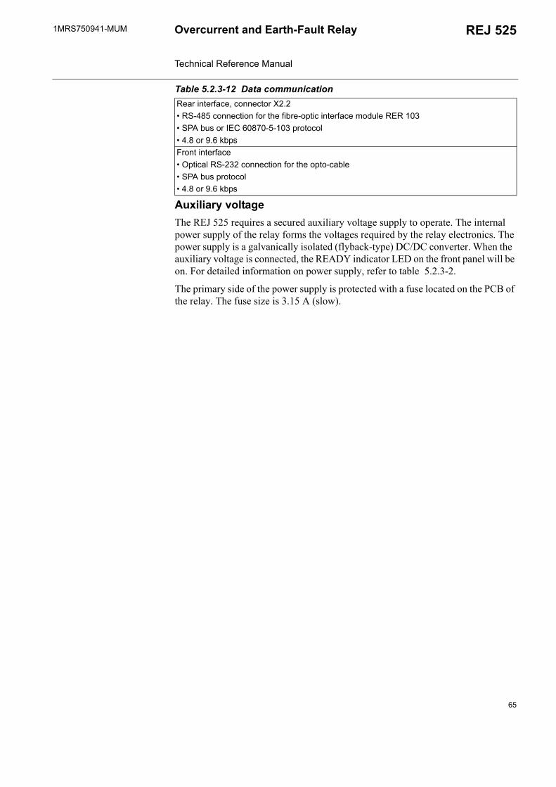
1MRS750941-MUM REJ 525Overcurrent and Earth-Fault Relay Technical Reference Manual
Auxiliary voltageThe REJ 525 requires a secured auxiliary voltage supply to operate. The internal power supply of the relay forms the voltages required by the relay electronics. The power supply is a galvanically isolated (flyback-type) DC/DC converter. When the auxiliary voltage is connected, the READY indicator LED on the front panel will be on. For detailed information on power supply, refer to table 5.2.3-2.
The primary side of the power supply is protected with a fuse located on the PCB of the relay. The fuse size is 3.15 A (slow).
Table 5.2.3-12 Data communicationRear interface, connector X2.2 RS-485 connection for the fibre-optic interface module RER 103 SPA bus or IEC 60870-5-103 protocol 4.8 or 9.6 kbpsFront interface Optical RS-232 connection for the opto-cable SPA bus protocol 4.8 or 9.6 kbps
65

66

1MRS750941-MUM REJ 525Overcurrent and Earth-Fault Relay Technical Reference Manual
6. Ordering informationOrder number (I0 inputs 0.2 A/1 A) REJ525B 412BAA
(Article nr:1MRS091412-BAA)Order number (I0 inputs 1 A/5 A) REJ525B 415BAA
(Article nr:1MRS091415-BAA)Protective cover for rear connectors 1MRS060132Flush mounting kit 1MRS050209Semi-flush mounting kit 1MRS050253Wall mounting kit 1MRS050240Side-by-side mounting kit 1MRS05024119" Rack mounting kit 1MRS050257 Optic bus connection module 1MRS090701 (RER 103)Opto-cable 1MKC950001-2
67

68
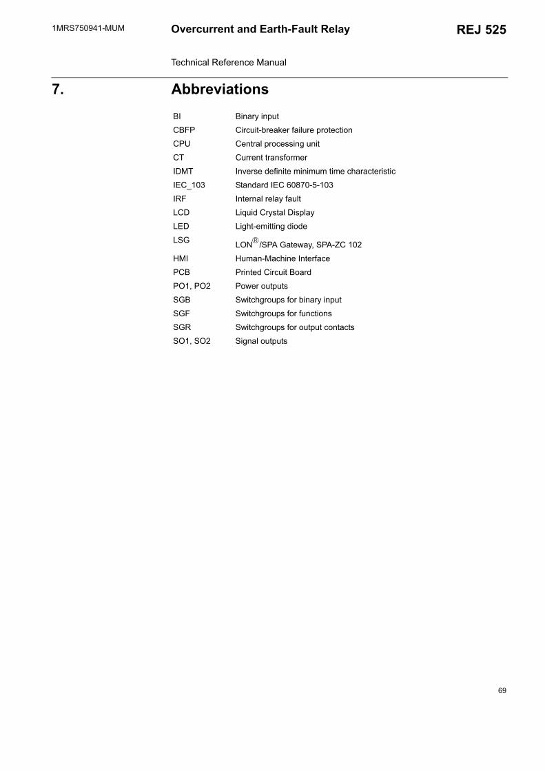
1MRS750941-MUM REJ 525Overcurrent and Earth-Fault Relay Technical Reference Manual
7. AbbreviationsBI Binary input
CBFP Circuit-breaker failure protection
CPU Central processing unit
CT Current transformer
IDMT Inverse definite minimum time characteristic
IEC_103 Standard IEC 60870-5-103
IRF Internal relay fault
LCD Liquid Crystal Display
LED Light-emitting diode
LSG LON/SPA Gateway, SPA-ZC 102
HMI Human-Machine Interface
PCB Printed Circuit Board
PO1, PO2 Power outputs
SGB Switchgroups for binary input
SGF Switchgroups for functions
SGR Switchgroups for output contacts
SO1, SO2 Signal outputs
69

70

1MRS750941-MUM REJ 525Overcurrent and Earth-Fault Relay Technical Reference Manual
8. Check lists Table 8.-1 Setting group 1
Variable Group 1 (R, W, P) Setting range Default
settingCustomer's setting
Set start value of stage I> S41 0.30...5.00 x In 0.30 x InOperate time or time multiplier k of stage I>
S42 0.05...300 s 0.05 s/ 0.05
Set start value of stage I>> S43 0.30...35.0 x In 0.30 x InOperate time of stage I>> S44 0.04...300 s 0.04 sSet start value of stage ∆I> S65 10...100% 100%Operate time of stage ∆I> S66 1...300 s 60 sSet start value of stage I0> S45 0.01...0.80 x In 0.01 x InOperate time or time multiplier k of stage I0>
S46 0.05...300 s 0.05 s/ 0.05
Set start value of stage I0>> S47 0.05...4.00 x In 0.05 x InOperate time of stage I0>> S48 0.04...300 s 0.04 s
Checksum, SGF1 S49 0...31 0Checksum, SGF2 S50 0...127 64Checksum, SGF3 S51 0...31 0Checksum, SGF4 S52 0...32 0Checksum, SGF5 S53 0...32 0Checksum, SGB1 S54 0...255 0Checksum, SGB2 S67 0...1 0Checksum, SGR1 S55 0...15 12Checksum, SGR2 S56 0...15 3Checksum, SGR3 S57 0...15 12Checksum, SGR4 S58 0...15 3Checksum, SGR5 S59 0...15 12Checksum, SGR6 S60 0...15 3Checksum, SGR7 S61 0...15 12Checksum, SGR8 S62 0...15 3Checksum, SGR9 S63 0...15 12Checksum, SGR10 S64 0...15 3
Table 8.-2 Setting group 2
Variable Group 2 (R, W, P) Setting range Default
settingCustomer's setting
Set start value of stage I> S81 0.30...5.00 x In 0.30 x InOperate time or time multiplier k of stage I>
S82 0.05...300 s 0.05 s/ 0.05
Set start value of stage I>> S83 0.30...35.0 x In 0.30 x InOperate time of stage I>> S84 0.04...300 s 0.04 sSet start value of stage ∆I> S105 10...100% 100%Operate time of stage ∆I> S106 1...300 s 60 sSet start value of stage I0> S85 0.01...0.80 x In 0.01 x InOperate time or time multiplier k of stage I0>
S86 0.05...300 s 0.05 s/ 0.05
71
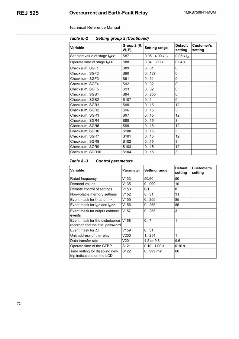
1MRS750941-MUMOvercurrent and Earth-Fault Relay Technical Reference Manual
REJ 525
Set start value of stage I0>> S87 0.05...4.00 x In 0.05 x InOperate time of stage I0>> S88 0.04...300 s 0.04 s
Checksum, SGF1 S89 0...31 0Checksum, SGF2 S90 0...127 0Checksum, SGF3 S91 0...31 0Checksum, SGF4 S92 0...32 0Checksum, SGF5 S93 0...32 0Checksum, SGB1 S94 0...255 0Checksum, SGB2 S107 0...1 0Checksum, SGR1 S95 0...15 12Checksum, SGR2 S96 0...15 3Checksum, SGR3 S97 0...15 12Checksum, SGR4 S98 0...15 3Checksum, SGR5 S99 0...15 12Checksum, SGR6 S100 0...15 3Checksum, SGR7 S101 0...15 12Checksum, SGR8 S102 0...15 3Checksum, SGR9 S103 0...15 12Checksum, SGR10 S104 0...15 3
Table 8.-3 Control parameters
Variable Parameter Setting range Default setting
Customer's setting
Rated frequency V133 50/60 50Demand values V135 0...999 10Remote control of settings V150 0/1 0Non-volatile memory settings V152 0...31 31Event mask for I> and I>> V155 0...255 85Event mask for I0> and I0>> V156 0...255 85
Event mask for output contacts' events
V157 0...255 3
Event mask for the disturbance recorder and the HMI password
V158 0...7 1
Event mask for ∆Ι V159 0...31Unit address of the relay V200 1...254 1Data transfer rate V201 4.8 or 9.6 9.6Operate time of the CFBP S121 0.10...1.00 s 0.10 sTime setting for disabling new trip indications on the LCD
S122 0...999 min 60
Table 8.-2 Setting group 2 (Continued)
Variable Group 2 (R, W, P) Setting range Default
settingCustomer's setting
72
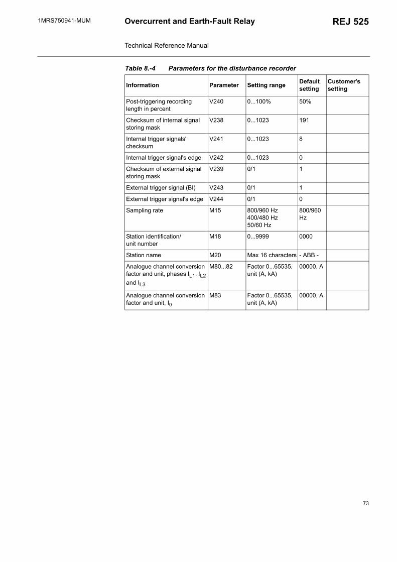
1MRS750941-MUM REJ 525Overcurrent and Earth-Fault Relay Technical Reference Manual
Table 8.-4 Parameters for the disturbance recorder
Information Parameter Setting range Default setting
Customer's setting
Post-triggering recording length in percent
V240 0...100% 50%
Checksum of internal signal storing mask
V238 0...1023 191
Internal trigger signals' checksum
V241 0...1023 8
Internal trigger signal's edge V242 0...1023 0
Checksum of external signal storing mask
V239 0/1 1
External trigger signal (BI) V243 0/1 1
External trigger signal's edge V244 0/1 0
Sampling rate M15 800/960 Hz400/480 Hz50/60 Hz
800/960 Hz
Station identification/ unit number
M18 0...9999 0000
Station name M20 Max 16 characters - ABB -
Analogue channel conversion factor and unit, phases IL1, IL2 and IL3
M80...82 Factor 0...65535, unit (A, kA)
00000, A
Analogue channel conversion factor and unit, I0
M83 Factor 0...65535, unit (A, kA)
00000, A
73

74

1MRS750941-MUM REJ 525Overcurrent and Earth-Fault Relay Technical Reference Manual
9. Service
When the protection relay is used under the conditions specified in Section 5.2.3. Technical data, it is practically maintenance-free. The protection relay electronics include no parts or components subject to abnormal physical or electrical wear under normal operating conditions.
If the relay fails in operation or if the operating values considerably differ from those mentioned in the protection relay specifications, the relay should be overhauled. All repairs are to be taken by the manufacturer. Please contact the manufacturer or its nearest representative for further information about checking, overhaul and recalibration of the relay.
To achieve the best possible operation accuracy, all parts of the protection relay have been calibrated together. In the event of malfunction, please consult your relay supplier.
If the protection relay is sent to the manufacturer, it has to be carefully packed to prevent further damage to the device.
75

76
1MRS750941-MUM REJ 525Overcurrent and Earth-Fault Relay Technical Reference Manual
10. Index
AApplication ............................................................................................... 11Auxiliary voltage .......................................................................... 60, 62, 65
BBinary input ........................................................................................ 61, 62Binary input test ....................................................................................... 40Block diagram .......................................................................................... 19
CCBFP ........................................................................................................ 16Check lists ................................................................................................ 71Checksum calculation ............................................................................... 31Communication ports ............................................................................... 44Communication protocol .......................................................................... 45Comtrade .................................................................................................. 42Configuration ...................................................................................... 11, 18Connection diagram .................................................................................. 12Control parameters ................................................................................... 55Counter ..................................................................................................... 44
DData communication ................................................................................. 65Demand values ......................................................................................... 40Design description .................................................................................... 58Dimensions ............................................................................................... 62Disturbance recorder .................................................................... 16, 40, 53Disturbance recorder data ......................................................................... 41
EEarth-fault unit .......................................................................................... 20Electromagnetic compatibility tests ......................................................... 63Energizing inputs ...................................................................................... 62Environmental conditions ......................................................................... 11Environmental tests .................................................................................. 63Event code .................................................................................... 43, 48, 49External parameterization ......................................................................... 58
FFault code ........................................................................................... 17, 58Features ....................................................................................................... 9Function test ............................................................................................. 40
HHMI .................................................................................................... 16, 30
77

1MRS750941-MUMOvercurrent and Earth-Fault Relay Technical Reference Manual
REJ 525
IIEC 60255 standard .................................................................................. 21IEC 60870-5-103 ...................................................................................... 45Indication messages ............................................................................ 39, 58Input/output connections .......................................................................... 58Input/output signals .................................................................................. 57Inputs .................................................................................................. 16, 57Internal relay fault ........................................................................ 17, 58, 61
LLatching feature ........................................................................................ 32LCD .................................................................................................... 16, 58LED .............................................................................................. 17, 39, 58LED test ................................................................................................... 40Local parameterization ............................................................................. 58LON bus ................................................................................................... 44
MMaster reset ........................................................................................ 42, 43Measurements ........................................................................................... 18Measuring range ....................................................................................... 62
NNew trip indication ................................................................................... 37Non-volatile memory ......................................................................... 17, 37
OOrdering information ................................................................................ 67Output signals ........................................................................................... 57Overcurrent unit ....................................................................................... 19
PParameterization ....................................................................................... 58Parameters for the disturbance recorder ............................................. 53, 73Password ............................................................................................ 16, 50Phase discontinuity protection ................................................................. 20Power outputs (PO1, PO2) ..................................................... 16, 57, 61, 63Power supply ............................................................................................ 62Product functions ..................................................................................... 15
RRD-type characteristic .............................................................................. 23Recorded data ..................................................................................... 43, 52Requirements ............................................................................................ 11RI-type characteristic ............................................................................... 22
78
1MRS750941-MUM REJ 525Overcurrent and Earth-Fault Relay Technical Reference Manual
SSelf-supervision .................................................................................. 17, 58Serial communication ......................................................................... 44, 61Setting groups ........................................................................................... 30Settings ............................................................................................... 30, 51SGB1 ........................................................................................................ 35SGF1...SGF5 ............................................................................................ 32SGR1...SGR10 .................................................................................... 35, 59Signal diagram .......................................................................................... 18Signal outputs (SO1, SO2) ..................................................... 16, 57, 61, 63SPA bus communication protocol ............................................................ 44Switchgroups ............................................................................................ 31
TTechnical data ........................................................................................... 62Technical data on protection functions ..................................................... 38Time/current characteristics ..................................................................... 21
WWeighting factor ....................................................................................... 31
79


ABB OyDistribution Automation P.O. Box 699FI-65101 VaasaFINLANDTel. +358 10 22 11Fax. +358 10 224 1094www.abb.com/substationautomation
1MR
S75
0941
-MU
M E
N 1
1.20
05