technical report 3 - engr.psu.edu 3...core and shell timothy maffett 2012 submitted: november...
TRANSCRIPT
2012
Technical Report 3
Timothy Maffett
Construction Management
Advisor: Dr. Messner
San Anto, California
Submitted: November 12, 2012
Research Facility
Core and Shell

[TECHNICAL REPORT 3] November 12, 2012
Construction Management | Timothy Maffett i
Executive Summary
Research Facility Core and Shell (RFCS) is a 127,000 square foot, 4 story building with
underground parking which houses both laboratory and office space. It is located in Southern
California and was proposed as a solution to the growing needs of the company, Faction, which
produces new technologies used for medical research. The location of RFCS is set on the
existing campus next to other buildings used for similar purposes. The owner contracted DPR
Construction as the General Contractor and the scope of this portion of the project consisted of
the foundation, the main structural systems, the exterior façade, and the core mechanical and
electrical units. The final cost of the core and shell was approximately 20 million dollars.
Sustainability was a major initiative set forth by the owner. The project has attained
LEED Silver and is only a few credits away from LEED Gold which the owner has shown some
interest in eventually pursuing. The major components of the building which accounted for the
majority of the credits were water efficiency, sustainable site improvements, energy efficient
wall panels, increased indoor air quality, and day lighting. The construction team at RFCS also
implemented a robust waste management and recycling system which accounted for credits
too.
Schedule acceleration scenarios were reviewed as a means to gain a better
understanding towards research opportunities. The critical path is composed of 3-D systems
coordination, procurement of air handlers and masonry veneer, fabrication of structural steel,
pouring the spread footings, erecting the structure steel, and building the exterior façade. The
main component that appears to show the most room for schedule acceleration is the
construction of the exterior façade. Prefabricated panels could prove to be a successful
alternate solution to the current stick built approach.
Another topic that was investigated which could help in understanding research
opportunities was Value Engineering. The owner chose to implement value engineering ideas
such as a prefabricated stair system and cost efficient bathroom tiles. Ideas that were
suggested but not implemented were an alternate masonry veneer, the removal of the
architectural ceiling in the lobbies, and the removal of the underground parking garage.
On November 6th, 2012 the 21st PACE Roundtable conference commenced at Penn State
University in University Park, PA. The conference covered the research opportunities the Penn
State Architectural Engineering Department is involved with as well as discussed the benefits of
the BIM Studio that is offered as opposed to the traditional studio sessions. Once the main
lectures were complete students, faculty, and professionals were split into small breakout
sessions. The two sessions I attended were Supply Chain- Integrating Strategies and
Technologies and Supply Chain- Modularization. In the first session we discussed a barcoding

[TECHNICAL REPORT 3] November 12, 2012
Construction Management | Timothy Maffett ii
system that could help with tracking materials. In the second session we discussed the benefits
and challenges associated with prefabrication and modularization in construction. These
sessions, along with research into LEED, schedule acceleration, and value engineering helped in
identifying areas to perform technical analysis.
The areas that arose out of this investigation that call for technical analysis are
associated with the exterior façade construction, the masonry veneer selection, passive energy
systems, and BIM use for Operations and Maintenance. Exterior façade construction could
benefit from prefabricating the wall panels which could decrease the schedule duration due to
the critical nature of the activity. The masonry veneer was also critical due to the long lead
time of the order. Research into alternate materials that are local to Southern California could
result in a decreased lead time. Along with considering materials local to Southern California,
the local climate should also be considered and implementation of passive energy systems may
result in lower long term energy costs. Finally, BIM use for Operations and Maintenance could
improve efficiency of the maintenance crew once the project is turned over which could save
long term costs. All of these ideas will be considered when forming my final thesis proposal.

[TECHNICAL REPORT 3] November 12, 2012
Construction Management | Timothy Maffett iii
Table of Contents
Executive Summary..……………………………………………………………………………………………………………………………….i
Table of Contents……………………………………………………………………………………………………………………………………iii
LEED Evaluation…………….………………………………………………………………………………………………………………………..1
Schedule Acceleration Scenarios……..………………………………………………………………………………………………………4
Value Engineering Topics…………………………………………………………………………………………………………………………7
Critical Industry Issues (PACE Roundtable)……………………………………………………………………………………………..9
Problem Identification and Technical Analysis…………….…………………………………………………………………………14
Appendix A- RFCS LEED Scorecard
Appendix B- PACE Roundtable Notes

[TECHNICAL REPORT 3] November 12, 2012
Construction Management | Timothy Maffett 1
LEED Evaluation
Sustainable construction proved to be an important matter at RFCS. The owner and the
team began planning towards sustainable design and construction from day one which
influenced the process and nature of the building throughout the entire project. This early
planning allowed the core and shell portion of the project to attain LEED Silver with a future
plan of attaining LEED Gold. The team is still finishing the final documentation and system
calibration which could result in this shift from silver to gold once approved by the USGBC. The
following table summarizes the main categories of the LEED rating system and the complete
breakdown can be found in Appendix A- LEED Scorecard. The “Targeted” category indicates
points the team expects to achieve and the “?” category indicates points that could be possible
but are unlikely to be achieved.
Table 1: LEED Scorecard Summary
LEED Scorecard Summary
Category Yes Targeted ? No Points Possible
Sustainable Sites 2 7 10 7 26
Water Efficiency 8 2 0 0 10
Energy and Atmosphere 1 14 12 8 35
Materials and Resources 2 4 2 6 14
Indoor Environmental Quality 5 9 1 0 15
Innovation and Design Process 1 5 0 0 6
Regional Priority Credits 1 2 1 0 4
Total 20 43 26 21 110
Since the LEED certification the team pursued did not include the tenant improvement,
the team had to pay special attention to the requirements set forth by the USGBC to ensure the
points were totaled correctly in relation to the core and shell. The team was challenged by this
based on the unique contract situation but worked with USGBC representatives to finish
successfully.
The areas that the team pursued to the greatest extent were Water Efficiency, Energy
and Atmosphere, and Indoor Environmental Quality. Important to the owner was to distinguish
the building as “green” and show leadership in sustainability. Along with this goal, the owner
wished to provide an indoor environment that was pleasing to the researchers in hopes of
creating a more productive work environment. To give a further understanding of the LEED
goals on RFCS the following section will summarize and evaluate the main categories of the
LEED rating system and will conclude with an overall critical evaluation of the LEED plan the
team utilized for construction.

[TECHNICAL REPORT 3] November 12, 2012
Construction Management | Timothy Maffett 2
Sustainable Sites
The team at RFCS took a very appropriate approach to the Sustainable Sites portion of
the LEED grading system. The team pursued points in this section based on site selection,
protecting nearby habitats, storm water control, and reducing the heat island effect. The
subcategories the team did not pursue resided mainly on community connectivity and public
transportation access. While these are two large categories, it makes sense that the team
chose not to pursue community connectivity based on the need for privacy in the fast paced
and competitive field in which the owner does business as well as the poor nature of the public
transportation outside of San Diego.
Water Efficiency
Water efficiency was a very important factor to the owner at RFCS. They saw this as a
critical category in which they could achieve LEED points and also save money in long term
utility costs. They chose to pursue every point possible in this section by choosing an efficient
landscaping plan as well as reducing water in the building by 40% compares to industry
standards. They reduced water demands in the building by reusing gray water where
appropriate and installing plumbing fixtures rated for low water use. The LEED strategy the
team pursued for Water Efficiency is quite commendable.
Energy and Atmosphere
The Energy and Atmosphere portion of the LEED rating system proved to be another
instance where the owner could tally numerous credits as well as save money in long term
utility costs. The main goals regarding Energy and Atmosphere were to create an energy
efficient exterior envelope and to calibrate and commission the main systems of the building to
maximize performance. While the team succeeded in creating a core and shell that is about
25% more energy efficient than industry standard, they missed credit opportunities and long
term cost savings by simply stopping there. With current trends of energy cost increases, utility
costs are becoming more and more important. A recommendation to the team by this
researcher would be to focus more on an envelope that could optimize energy performance to
a greater extent. Various systems exist that could achieve these rates at a similar cost while still
maintaining the architectural integrity the owner desires.
Materials and Resources
The team chose to put heavy emphasis on this portion of the LEED scorecard. While not
a highly weighted category by USGBC, the team at DPR holds high core values in sustainability
and saw this as a section that they could have direct control over. The points they accrued in
this section dealt directly with construction waste management and recycling plans. The team

[TECHNICAL REPORT 3] November 12, 2012
Construction Management | Timothy Maffett 3
worked rigorously to maintain constant recycling efforts and impressed the owner based on the
level of detail and control they maintained throughout the project. This researcher’s view is
that the team should be highly commended for their efforts as this is an issue that can slip in a
high paced construction project.
Indoor Environmental Quality
Optimized Indoor Environmental Quality is an issue that has come into the spotlight in
recent years. Studies have proven that employees are more productive and happier when the
environment they work in is enjoyable. The owner, as well as the designers and construction
team, took this into consideration targeting almost all of the points possible in this category. By
using low-emitting materials for almost all of the interior systems, maintaining high indoor air
quality, and focusing on large full story windows and curtain walls throughout the building; the
team was able to create a pleasing indoor environment for the future tenants of the space.
Both the design and construction teams worked hand-in-hand to produce what the owner
deemed as a very successful space.
Regional Priority Credits
The team was able to gain a few extra LEED credits in this category based on an overlap
between the regional credits of the area and requirements that they had fulfilled in the other
major LEED Scorecard categories. These overlaps included day lighting, water efficient
landscaping, and innovative wastewater technologies.
Overall Evaluation of LEED Strategy at RFCS
The LEED Strategy at RFCS proved to be highly successful. By focusing on areas that
provided long term cost savings and relevance to the actual construction site, the team was
able to utilize sustainability to not only meet the necessary point requirements, but also
produce a building that benefited in all respects by “thinking green”. They were able to not
only meet the owner’s request of LEED Silver but take that one step further and will most likely
achieve LEED Gold. They were able to create a sustainable project and save the owner money
in long term utility costs. An area that could see improvement is selecting an envelope that has
increased energy efficiency properties while still maintaining the similar architectural qualities
and cost. Aside from this small criticism, the overall impression of the LEED strategy at RFCS by
this researcher is very high. The team proved that with some consideration into sustainability,
they could provide a successful project while benefiting the public image of the owner,
providing an enjoyable environment for the tenants to work, and saving long-term utility costs.
[TECHNICAL REPORT 3] November 12, 2012
Construction Management | Timothy Maffett 4
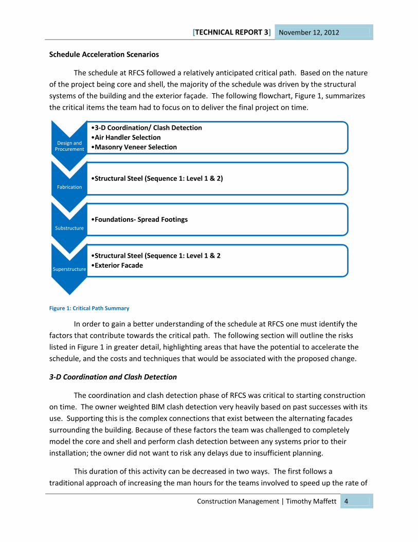
Schedule Acceleration Scenarios
The schedule at RFCS followed a relatively anticipated critical path. Based on the nature
of the project being core and shell, the majority of the schedule was driven by the structural
systems of the building and the exterior façade. The following flowchart, Figure 1, summarizes
the critical items the team had to focus on to deliver the final project on time.
Figure 1: Critical Path Summary
In order to gain a better understanding of the schedule at RFCS one must identify the
factors that contribute towards the critical path. The following section will outline the risks
listed in Figure 1 in greater detail, highlighting areas that have the potential to accelerate the
schedule, and the costs and techniques that would be associated with the proposed change.
3-D Coordination and Clash Detection
The coordination and clash detection phase of RFCS was critical to starting construction
on time. The owner weighted BIM clash detection very heavily based on past successes with its
use. Supporting this is the complex connections that exist between the alternating facades
surrounding the building. Because of these factors the team was challenged to completely
model the core and shell and perform clash detection between any systems prior to their
installation; the owner did not want to risk any delays due to insufficient planning.
This duration of this activity can be decreased in two ways. The first follows a
traditional approach of increasing the man hours for the teams involved to speed up the rate of
Design and Procurement
•3-D Coordination/ Clash Detection
•Air Handler Selection
•Masonry Veneer Selection
Fabrication
•Structural Steel (Sequence 1: Level 1 & 2)
Substructure
•Foundations- Spread Footings
Superstructure
•Structural Steel (Sequence 1: Level 1 & 2
•Exterior Facade

[TECHNICAL REPORT 3] November 12, 2012
Construction Management | Timothy Maffett 5
modeling to meet a more accelerated schedule of collaboration meetings. The costs associated
with this technique would mainly result from the increased man hours the contractors would
have to spend which would most likely either require an additional engineer or require
overtime. The second technique follows a more abstract approach. Recent trends in the
construction industry have shown that a “Big Room” environment in which all teams are
located in one area can increase the rate at which issues are resolved. If the owner was willing
to spend money on relocating the teams to one location during the clash detection phase, they
could see considerable decreases in the duration of this activity.
Air Handler Selection
RFCS consists mainly of the structure of the building but also includes the heavy core
electrical and mechanical equipment that will be used to energize and condition the building.
Of the various pieces of equipment that would be installed during core and shell, the air
handlers required were deemed the longest lead item of all. The team worked with the
architect during the procurement stage to ensure the air handlers were specified, submittals
were approved, and the order was placed to ensure on time arrival.
The team was able to make their decision quite quickly on this matter. The only viable
options for decreasing the duration on the air handlers’ delivery would be to decrease the time
taken to place the order by increased collaboration and planning or to pay the supplier extra to
speed up the delivery sequence. The first option could be achieved with little cost if proper
planning and collaboration was achieved. The second option would require increased costs
based on the costs the supplier deems are necessary to produce the materials quicker.
Masonry Veneer Selection and Procurement
The masonry veneer the owner and architect decided on would prove to be a
continuous challenge to the team at RFCS during procurement. In order to match the existing
architecture of the campus and remain within the budget, the owner decided on a stone that
would need to be ordered from India. Initially the team did not see this as a problem and did
not consider it a critical activity. Once construction had begun the team quickly noticed
difficulties with the supplier. Communication with the supplier was poor, and the stone
manufacturing was delayed by external factors. Once the team realized the importance of the
masonry veneer to the critical path of completion, the team increased attention towards the
task and were able to complete the activity on time.
The delivery schedule for the masonry veneer could be increased substantially by
choosing a different vendor. Perhaps one that is local in which the team could have face to face
interaction with on a regular basis. By choosing a vendor in India the team was able to save
money but at the cost of continuous delays to the delivery date. If the team were to spend

[TECHNICAL REPORT 3] November 12, 2012
Construction Management | Timothy Maffett 6
additional time searching for a vendor in the United States, they could most likely find a similar
material. This could add material costs but would allow the team to begin the masonry veneer
much sooner which could in turn decrease the entire schedule duration of the project.
Fabrication of Structural Steel (Sequence 1: Level 1 & 2)
The fabrication of the first two levels of structural steel at RFCS was a key activity in
guaranteeing that the team could begin erecting the superstructure on time. The engineers
took longer than expected to design the structural system which left the team little time to
finish details and as a result place the mill order. By delaying the erection of levels 1 and 2 the
team would in turn delay all of the trades that were scheduled to begin work on those floors
which would be costly to the project.
The schedule duration for fabrication of structural steel could be decreased by fast-
tracking the fabrication sequences to an even greater extent. It is currently structured to be
fabricated and delivered two floors at a time. If the team were able to package the steal into
smaller groupings such as one level at a time, the first level could be fabricated and delivered
without having to wait for the second level steel fabrication. This would allow for earlier steel
erection assuming other items on the critical path could be adjusted to fit an earlier start date.
The costs associated with this change would accrue mainly from increased planning time and
possibly additional costs due to smaller orders with the steel mill. These costs have the
potential to be offset by the time saved due to start date acceleration for structural steel
erection though and could possibly be worth investigating further.
Foundations- Spread Footings
The majority of the substructure at RFCS did not fall on the critical path. One item that
drove the critical path during this phase though was the spread footings that would eventually
support the load of the building. The installation of the footings was not the key issue here but
rather the time needed for the concrete to cure to the necessary strength to begin other work
related to the footings.
The time necessary for the concrete to cure to strength could be decreased by adding
an accelerant to the concrete mix. The accelerant would substantially increase the curing rate
of the concrete which could shave a few days off of the substructure schedule allowing the
trades following to begin work sooner. Costs associated with this change would be amassed
mainly by the additional time the structural engineer would have to spend reviewing the new
mix design compared to strength requirements as well as the increased cost of the concrete
mix containing the accelerant.

[TECHNICAL REPORT 3] November 12, 2012
Construction Management | Timothy Maffett 7
Structural Steel Erection (Sequence 1: Level 1 & 2)
As can be imagined based on the fabrication of structural steel levels 1 & 2 being on the
critical path, the structural steel erection of levels 1 & 2 also fell on the critical path. In order to
begin metal decking as well as pouring slab on deck and all other trades, steel erection of these
levels had to be complete.
The erection of structural steel would be difficult to speed up for RFCS. The existing
design of the system is already a simplified redundant bay scheme with very little room for
confusion. On top of this, the team utilized a side-plate system to support lateral loads which
decreases installation time compared to other systems. An option that could be considered for
decreasing the duration of this sequence could be to investigate the way in which the steel was
actually erected. Perhaps changes in the location of crane placement as well as the material
locations could allow for faster erection. Another option would be to work overtime which
would result in increased labor costs.
Exterior Façade Construction
The exterior façade proved to be the main item of concern at RFCS. The executed plan
involved erecting scaffolding around the building, stick building the walls, stick building the
window units, and hand placing the masonry veneer. This activity drove the schedule based on
the need for complete enclosure prior to doing large scope interior work such as drywall.
Of all the critical path items the exterior façade appears to show the most room for
schedule acceleration. The executed wall system plan involves a great amount of onsite
construction which can only start once other trades have finished the preceding work. If the
contractors were able to work with the designer and owner early in the project to prefabricate
these systems the schedule would be considerably reduced. Instead of spending time stick
building everything, they could hoist prefabricated wall panels and window units into place at a
much faster pace. Work could be completed off site on these systems immediately rather than
waiting on precedent activities to be finished. A prefabricated wall system would add costs
initially during the planning phase based on increased engineering costs and ordering the
material but could pay dividends in the long run. A prefabricated wall system would save costs
on labor, scaffolding, possibly material, and general conditions in the long term.
Value Engineering Topics
Value engineering is an essential practice during design and planning in which
suggestions are made for alternate systems or materials that will ideally produce the same
quality product at a lower cost. In the case of RFCS, value engineering was minor due to the

[TECHNICAL REPORT 3] November 12, 2012
Construction Management | Timothy Maffett 8
nature of the project. The majority of the core and shell scope entailed structural systems and
large scale mechanical equipment which leaves minimal area for the application of value
engineering. Areas that were considered for value engineering are listed in Table 2 below. The
table lists the original design, the alternative solution, and whether the idea was actually
implemented.
Table 2: Value Engineering at RFCS
Value Engineering
Original Design Alternative Solution Implemented?
Build stairways on site Use preassembled stairways Yes
High-end bathroom tiling More generic/ less cost tiling Yes
Masonry veneer to match other buildings on campus
Cheaper masonry veneer but did not completely match surrounding buildings
No
Architectural ceiling in lobbies Eliminate and build simple ceiling No
Underground parking Eliminate and build parking lot No
One of the main areas the general contractor, DPR, saw for cost savings while
maintaining quality was in the nature of the stair units. The original design called for assembly
on site which would increase the cost as well as increase the schedule duration for the activity.
DPR offered a solution in which the stairs could be assembled off site at a lower cost and could
be installed much faster once brought to site. Minor problems occurred during the planning
phase of this resulting in some architectural changes to the stairwells. This did not detract from
any goals set forth by the owner and correlated with cost savings which the owner saw as a
success.
Another area that was reviewed during the design and planning phase was the tiles that
would be used in the core restrooms of the building. Under the initial design these tiles were to
be high end and were expensive. After research into substitute products, the team came across
a tile that was very similar to the one in the initial design. Once the alternate tile was
determined the owner reviewed the option and was pleased with the aesthetics it offered
while keeping the material costs low. This correlated with the owner’s goal of providing an
architectural pleasing space while keeping the project under budget.
While the owner was willing to make the switch on a substitute bathroom tile, they
were not willing to make the switch on the masonry veneer that was the face of the exterior
façade throughout the majority of the enclosure. It was of paramount importance for RFCS to
match the existing campus and the owner was willing to spend the extra money here. Though
alternative solutions were investigated, the team had little time to spend researching due to
the constraint of the long lead time on the veneer. The masonry veneer was chosen and almost

[TECHNICAL REPORT 3] November 12, 2012
Construction Management | Timothy Maffett 9
immediately specified by the owner and architect. It would need to be supplied from a
manufacturer in India.
Another item the owner was not willing to part with was the architectural ceiling used in
the main lobby of each floor. It is a curved ceiling which gives the feeling of compression and
release as you walk through it. The owner found it critical to incorporate items that add
interest to the interior space in hopes of creating a better environment for their workers. DPR
offered solutions to this that were more basic and less costly but the owner was willing to
spend the extra money here in hopes of generating a better environment for the employees
which would in turn raise profits.
A final area of value engineering that was considered during the design phase was
eliminating the underground parking garage and building a parking lot in the space next to the
building. Initial thoughts were that this would be a valuable change but developments in other
areas of the owners business would result in the need for yet another building on campus in the
space intended for the parking lot. Based on this event the owner was convinced that other
space on campus would be necessary for future construction and that in the long term an
underground parking garage would make the most sense. They accumulated more costs in the
present but protected the investment into space availability for future project needs.
Though the core and shell offered only a few opportunities for value engineering, the
team at RFCS was able to work together to offer solutions for cost savings to the owner. Ideas
such as the prefabricated stair system and cost efficient bathroom tiles saved costs while
maintaining the quality and goals of the owner. Ideas such as the masonry veneer substitute,
removal of the architectural ceiling in the hallway, and removal of the underground parking
garage demonstrated areas in which the owner would have to sacrifice goals in order to save
costs and were not implemented. In future studies these topics will be considered to influence
which areas will be pursued as depths and breadths for my final thesis proposal.
Critical Industry Issues (PACE Roundtable)
Of the many opportunities we are presented with outside of the normal curriculum, the
PACE Roundtable on November 6th, 2012 demonstrated one of the best environments of
collaboration between student and industry professionals yet. The conference opened with
presentations by Dr. Robert Leicht and Mr. Robert Holland in which they described the many
research studies that the Penn State AE Department has been conducting as well as a summary
of the BIM studio that Penn State offers. Dr. Leicht described the studies that both
professionals and students at Penn State are working on which include the Lean and Green
Delivery project in which Penn State has partnered with the University of Colorado, a

[TECHNICAL REPORT 3] November 12, 2012
Construction Management | Timothy Maffett 10
retrofitting and auditing application that can be used to quickly gauge the energy use in a
building, safety in relation to building “green”, and studies of student behaviors in team
environments to name a few.
Mr. Holland followed this by describing how the BIM studio forces the students to work
in an IPD type environment in which collaboration makes or breaks the project. It was very
interesting to see what the students had to say once Mr. Holland opened questions to the floor.
I found it particularly interesting to hear directly from other students who participated in the
BIM studio first hand describing the role of a CM on a team like this. It seemed to be a general
consensus that performing a project under this environment really does not add work to the
job of the CM but rather changes their role. This seems to contradict many opinions I have
heard regarding the IPD approach to building which provides some optimism towards the
future of increased collaboration in the construction industry. After the students discussed
their opinions of the BIM Studio the conference moved from the large room to small breakout
sessions in which we were given the opportunity to pick what topics we would like to discuss
further. I chose to attend Supply Chain- Integrating Strategies and Technologies during Session
#1 and Supply Chain- Modularization during Session #2. Both sessions were valuable and
sparked intriguing discussions.
Session #1: Supply Chain- Integrating Strategies and Technologies
The main focus of this session is hard to state with one word but rather followed an
unorganized, sporadic flow. The conversation jumped from managing deliveries, to challenges
faced by Mr. Bryan Franz in ordering elevator enclosures from Italy for the National Cathedral
Project, to procurement strategies, to communication management, and finally to the
technology that can help the supply chain on a jobsite.
The general consensus from the professionals in the room was that of frustration with
the supply chain that exists during construction. Based on the unique nature of each project
and the many parties involved, the chances of completing a project from start to finish without
some roadblocks in the supply chain are very low. They stressed the importance of continued
communication with the parties involve. Mr. Bill Moyer, one of the industry attendees,
described the communication process as “the squeaky wheel still gets the grease”. What he
meant by this was that the louder and more persistent you are in tracking down items and
deliveries, the more attention you will receive. He made it clear that personal connections are
the key to success in construction. After hearing corroborating stories from the other
professionals in the room, my thoughts began to shift towards targeting a solution to these
frustrations. Others seemed to share the same interest and the topic of discussion shifted from
the problems we are faced with towards solutions to those problems that are currently
trending in the industry.

[TECHNICAL REPORT 3] November 12, 2012
Construction Management | Timothy Maffett 11
I found that in particular the most beneficial of those solutions regarded technologies
we can use to increase efficiency in the supply chain process. The focus of this in particular was
that of bar-coding equipment on a vendor level with information that will be needed all the
way through operations and maintenance. The idea seems so practical and I am very surprised
that this does not already exist in the industry. Instead of replicating work time and again as
the equipment goes through the supply chain, why not input the relevant information once in a
way that can be easily accessed by all of the parties? Imagine the time and costs that could be
saved by extra thought taken early in the process. The idea of barcoding equipment could go
very far in regards to RFCS based on the intensity of the final mechanical, electrical, and
research equipment demand. It would be interesting to compare the time the engineers on
site spend during turnover under the current plan and compare that to a situation where the
information could auto-populate their systems based on a scan of a barcode.
Of the few industry professionals that attended this session, Mr. Bill Moyer seemed to
know a great deal about the trends in the industry regarding barcoding equipment. I plan to
contact Mr. Moyer through the next few weeks to hopefully discuss this topic to a greater
extent. His full contact information is:
Mr. Bill Moyer
James G. Davis Construction Corporation
12530 Parklawn Dr.
Rockville, MD 20852
Session #2: Supply Chain- Modularization
The focus of Session #2 followed a more direct discussion relating to current trends of
modularization in the construction industry. We discussed the benefits and risks associated
with modularizing as well as the many challenges that one must overcome to see success by
using it. In respect to the types of modularization we discussed, the main categories included
prefabricated mechanical and electrical runs, prefabricated wall panels, and prefabricated
windows. The following breakdowns summarize the requirements for successful modularized
project delivery, the challenges that are associated with it, and the positive outcomes if
executed correctly according to the industry professionals present.
Requirements for Successful Modularized Project Delivery
Make prefabrication part of the design
Must be up-front thought process

[TECHNICAL REPORT 3] November 12, 2012
Construction Management | Timothy Maffett 12
Owner has to want modularization
Delivery method must support prefabrication
Contract must outline modularization requirements
Subcontractors must be familiar with the differences associated with building modular
Collaboration early in design is necessary
Trust between the teams and a team attitude is essential
Project must support it
Challenges Associated with Modularization
Increased planning
Site logistics
Transportation of the prefabricated systems
Tolerances with connection points
Aesthetics of the final assembly
Module size must be “just right”
Design variations throughout construction
Addition of large equipment required to lift the larger modules
Positive Outcomes of Modularizing
Cost decreases
Schedule acceleration
Cleaner job site
Decreases the busyness of jobsite
Reduction in accidents on site
The majority of the discussion seemed logical and followed what we have learned thus
far at Penn State in our AE classes in which modularization is fully praised. While most
conversation reinforced what we have already learned, I was surprised to hear that
modularization is not right for every project. My impression going into the meeting was that if
modular systems are implemented, the project will always see success. Based on the
testimonials of the industry professionals we learned that vague contract requirements,
intricate project types, and indecisive architects can cause serious problems when it comes to
modularization. A vague contract can lead to arguments between parties rather than a team
attitude and intricate projects often require very high tolerance precision which must be
assembled on site. Indecisive architects can make decisions late enough that it impacts the
time needed to prefabricate the necessary components and can even make it impossible to

[TECHNICAL REPORT 3] November 12, 2012
Construction Management | Timothy Maffett 13
complete on time. These issues must be considered when deciding on the extent of
modularization one chooses on their project.
RFCS stands to benefit from modularization. In particular RFCS stands to benefit from
modularizing the core mechanical chase, the stick built windows used in the majority of the
exterior, and possibly the exterior façade which was stick built with a masonry veneer installed
by hand. The core mechanical chase could be prefabricated off site and installed much quicker
than building the system piece by piece on site. This would decrease the interior working
environment congestion as well as accelerate the schedule of the interior work. It should be
noted that effectively modeling the systems in the design phase would be a major requirement
for this to be successful.
If the team at RFCS were to prefabricate the exterior façade including the punch out
window systems, they could benefit greatly. The exterior façade drove the critical path and
accrued the majority of the cost of construction. If the façade was modularized the panels and
window systems could be hoisted with a crane into place at a much faster pace and most likely
at a lower cost due to this decrease in schedule duration. An important consideration at this
point would be to consult the architect to ensure a similar architectural aesthetic if the switch
to modularized panels was made.
Of all the industry professionals in the room, Ms. Christi Saunders caught my attention
as someone who understands modularization and would be willing to help with future
research. After the meeting I was able to discuss the opportunities at RFCS further with her and
she gave me very valuable insight. Her complete contact information is:
Contact: Ms. Christi Saunders
Mascaro Construction Company
PO Box 29540
Raleigh, NC 27626
[TECHNICAL REPORT 3] November 12, 2012
Construction Management | Timothy Maffett 14
Problem Identification and Technical Analysis Options
RFCS was built on time and at a cost suitable to the owner. The systems utilized and the
methods of implementation were effective. After review of the project thus far it seems as
though the majority of design and construction followed a logical approach but there are some
areas that are worth considering an alternate solution to that could result in more value to the
owner. Those problematic areas in which an alternate solution might be more appropriate are
listed in this section and a summary for each is provided.
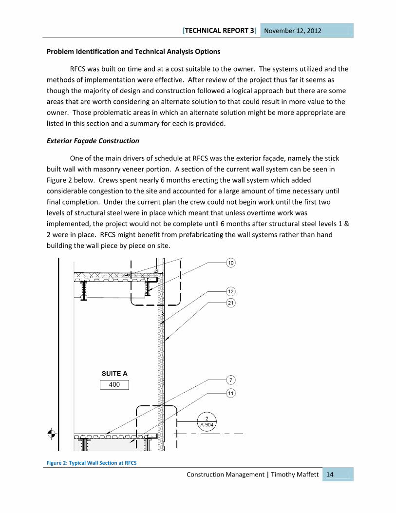
Exterior Façade Construction
One of the main drivers of schedule at RFCS was the exterior façade, namely the stick
built wall with masonry veneer portion. A section of the current wall system can be seen in
Figure 2 below. Crews spent nearly 6 months erecting the wall system which added
considerable congestion to the site and accounted for a large amount of time necessary until
final completion. Under the current plan the crew could not begin work until the first two
levels of structural steel were in place which meant that unless overtime work was
implemented, the project would not be complete until 6 months after structural steel levels 1 &
2 were in place. RFCS might benefit from prefabricating the wall systems rather than hand
building the wall piece by piece on site.
Figure 2: Typical Wall Section at RFCS

[TECHNICAL REPORT 3] November 12, 2012
Construction Management | Timothy Maffett 15
If the design team, the contractor, and the subcontractor for exterior façade were able
to team up early in the construction process and determine a suitable exterior panel system,
the exterior façade duration could be decreased drastically. By prefabricating wall systems,
crews could begin assembling the façade off site almost immediately and prepare them for
installation. The time needed for installation would be much smaller because scaffolding needs
would be decreased and crews could raise the panels at a much faster pace compared to the
current approach. General conditions costs would be decreased, the project would be safer,
quality could increase, and the project could complete at a sooner date.
In order to gain an understanding of the impacts of prefabricating the wall systems
rather than stick building them it is important to look into projects that have utilized systems of
this nature before and analyze the quality, cost, safety, and schedule that resulted from their
implementation. One such project could be the Millennium Science Building at Penn State
University which chose to implement prefabricated masonry panels. I could consult with
engineers who were involved with this and hopefully attain values for the costs and durations
of the exterior façade. After modifying the values to suit that of the San Diego area and
specifically RFCS, this could result in a very close comparison with reliable data. Schedule
comparisons would be necessary along with costs comparisons such as scaffolding needs, crane
use, manufacturing costs, installation costs, and general conditions.
Masonry Veneer Selection (Supply Chain)
Another area that is of interest to project schedule is the masonry veneer the owner
chose for RFCS. They chose a veneer that is produced in India based on the need for matching
aesthetics to buildings on the campus and the cost of manufacturing. The plant in India offered
the material necessary at the lowest price. Figure 3 below shows the masonry veneer being
discussed. A problem with choosing this material is that it became difficult to contact the
supplier overseas and resulted in delays.
Figure 3: Masonry Veneer

[TECHNICAL REPORT 3] November 12, 2012
Construction Management | Timothy Maffett 16
The team may have benefited by choosing a manufacturer and supplier who was local to
the United States; one which could offer a similar product and ensure that it would be delivered
to the site on time. If the manufacturer and supplier were local the risks of transportation as
well as communication hazards would be greatly decreased. To research into this topic it would
be important to interview the project team and document the issues that resulted in this delay.
It would be important to document the current transportation path the materials were sent
through and understand where possible delays could occur. Once the existing scenario was
understood, it would be important to look into local manufacturers and suppliers that could
produce a comparable material. The same studies of transportation paths as well as instances
where a local supply chain could be delayed would be important for comparison as well. Finally
a cost comparison between the local option and the current option from India could be
performed in which direct costs and indirect costs such as schedule were accounted for.
Minimal Passive Energy Saving Systems
The building systems at RFCS offer little control whatsoever over means of passively
cooling the building. In a moderate climate like San Diego a system that can respond to the
outdoor conditions makes great sense. With cool breezes, little severe weather and near 70
degree days on a regular basis; this building is the perfect model for downsizing the mechanical
systems and utilizing more passive means of cooling with a system that could measure outside
conditions and alter its functions in response. Figure 4 below shows a typical window unit
currently in place at RFCS
Figure 4: Typical Window at RFCS
A relatively simple solution to this problem would be a system that incorporated
operational windows into the exterior envelope. Under current plan the building was
constructed with non-operational window units allowing for little control. If the system

[TECHNICAL REPORT 3] November 12, 2012
Construction Management | Timothy Maffett 17
installed had sensors that could alter the response to the climate for the day, considerable
energy could be saved by reduced mechanical needs. For example the system on a favorable
day would automatically open the windows and downsize the mechanical needs in the building
while on a bad day would be able to close the windows and ramp up the mechanical needs back
to normal.
In order to gain a better understanding of the impacts of switching to a system like this
certain comparison must be made. It would be important to compare the construction costs
associated with each system as well as the long term energy costs of both systems. Energy
costs could be determined by modeling the energy uses in each scenario. The cost for controls
would also need to be considered along with the material costs of both options. A building that
I would use as a comparison is DPR’s office in Newport Beach. It is an office building similar to
RFCS but is fitted with completely operational windows with a system that is able to respond to
the daily whether. Comparisons could be made easily due to the proximity of the two buildings
and the similar markets in the area. By using the data from DPR’s office as well as quotes from
suppliers in the Southern California region, a relatively precise cost/benefit analysis could be
completed.
BIM Utilization
BIM was an integral component to successfully building RFCS. The team used it for clash
detection and saved a considerable amount of time because of it. Though clash detection was
a success, I see more uses for BIM in a project of this nature than were pursued. BIM has
various functions and more particularly to RFCS could be used for Operations and Maintenance
purposes.
Under the current plan, turnover consists of handing over a large booklet to the owner
composed of the various manuals and product data of the numerous components that went
into the building. This takes a large amount of time to produce and an even larger amount of
time for the eventual maintenance team to read and sift through. A solution to this could be a
3-D model that links the product data for each material to the visual components of the model.
Instead of maintenance crews spending time looking for data, they could figure out information
about a piece of equipment in a matter of seconds by referencing the model.
To perform a comparison study between the two approaches it would be important to
find an owner that is at the forefront of BIM Operations and Maintenance use and hear first-
hand what they think. It would be important to calculate the price of producing a model with
the necessary information for turnover as well as the eventual savings in time and workflow for
the maintenance teams. Another item to be considered would be a training program for the
maintenance teams to familiarize them with the new technology. Once all factors are

[TECHNICAL REPORT 3] November 12, 2012
Construction Management | Timothy Maffett 18
accounted for the two approaches could be closely compared and it could be determined
whether a BIM Operations and Maintenance plan would be effective at RFCS.

[TECHNICAL REPORT 3] November 12, 2012
Construction Management | Timothy Maffett 19
Appendix A- LEED Scorecard

LEED 2009 for New Construction and Major Renovations Research Facility Core and Shell
Project Checklist Date: November 12, 2012
2 7 10 7 Possible Points: 26Y T ? N d/C Notes:
Y C Prereq 1
1 d Credit 1 1
5 d Credit 2 5
1 d Credit 3 Brownfield Redevelopment 1
6 d Credit 4.1 6
1 d Credit 4.2 1
3 d Credit 4.3 Alternative Transportation—Low-Emitting and Fuel-Efficient Vehicles 3
2 d Credit 4.4 2
1 C Credit 5.1 Site Development—Protect or Restore Habitat 1
1 d Credit 5.2 Site Development—Maximize Open Space 1
1 d Credit 6.1 Stormwater Design—Quantity Control 1
1 d Credit 6.2 Stormwater Design—Quality Control 1
1 C Credit 7.1 Heat Island Effect—Non-roof 1
1 d Credit 7.2 1
1 d Credit 8 Light Pollution Reduction 1
8 2 0 0 Possible Points: 10
Y T ? N Notes:
Y d Prereq 1
4 d Credit 1 Water Efficient Landscaping 2 to 4
2 Reduce by 50% 2
2 No Potable Water Use or Irrigation 4
2 d Credit 2 Innovative Wastewater Technologies 2
4 d Credit 3 2 to 4
2 Reduce by 30% 2
1 Reduce by 35% 3
1 Reduce by 40% 4
1 14 12 8 Possible Points: 35
Y T ? N Notes:
Y C Prereq 1
Y d Prereq 2
Y d Prereq 3
1 7 6 5 d Credit 1 1 to 19
1 Improve by 12% for New Buildings or 8% for Existing Building Renovations 1
T Improve by 14% for New Buildings or 10% for Existing Building Renovations 2
T Improve by 16% for New Buildings or 12% for Existing Building Renovations 3
T Improve by 18% for New Buildings or 14% for Existing Building Renovations 4
T Improve by 20% for New Buildings or 16% for Existing Building Renovations 5
T Improve by 22% for New Buildings or 18% for Existing Building Renovations 6
T Improve by 24% for New Buildings or 20% for Existing Building Renovations 7
T Improve by 26% for New Buildings or 22% for Existing Building Renovations 8
T Improve by 28% for New Buildings or 24% for Existing Building Renovations 9
? Improve by 30% for New Buildings or 26% for Existing Building Renovations 10
? Improve by 32% for New Buildings or 28% for Existing Building Renovations 11
? Improve by 34% for New Buildings or 30% for Existing Building Renovations 12
? Improve by 36% for New Buildings or 32% for Existing Building Renovations 13
? Improve by 38% for New Buildings or 34% for Existing Building Renovations 14
N Improve by 40% for New Buildings or 36% for Existing Building Renovations 15
N Improve by 42% for New Buildings or 38% for Existing Building Renovations 16
N Improve by 44% for New Buildings or 40% for Existing Building Renovations 17
N Improve by 46% for New Buildings or 42% for Existing Building Renovations 18
N Improve by 48%+ for New Buildings or 44%+ for Existing Building Renovations 19
4 3 d Credit 2 1 to 7
? 1% Renewable Energy 1
? 3% Renewable Energy 2
? 5% Renewable Energy 3
? 7% Renewable Energy 4
N 9% Renewable Energy 5
N 11% Renewable Energy 6
N 13% Renewable Energy 7
2 C Credit 3 2
2 d Credit 4 2
3 C Credit 5 3
2 C Credit 6 2
Energy and Atmosphere
Enhanced Commissioning
Enhanced Refrigerant Management
Measurement and Verification
Green Power
Minimum Energy Performance
Construction Activity Pollution Prevention
Site Selection
Development Density and Community Connectivity
Alternative Transportation—Public Transportation Access
Alternative Transportation—Bicycle Storage and Changing Rooms
Optimize Energy Performance
On-Site Renewable Energy
Sustainable Sites
Water Efficiency
Alternative Transportation—Parking Capacity
Heat Island Effect—Roof
Water Use Reduction—20% Reduction
Fundamental Refrigerant Management
Water Use Reduction
Fundamental Commissioning of Building Energy Systems
LEED 2009 for New Construction and Major Renovations Project Checklist 1 of 1

2 4 2 6 Possible Points: 14
Y T ? N Notes:
Y d Prereq 1
3 C Credit 1.1 1 to 3
N Reuse 55% 1
N Reuse 75% 2
N Reuse 95% 3
1 C Credit 1.2 Building Reuse—Maintain 50% of Interior Non-Structural Elements 1
1 1 C Credit 2 1 to 2
1 50% Recycled or Salvaged 1
T 75% Recycled or Salvaged 2
1 1 C Credit 3 1 to 2
1 Reuse 5% 1
N Reuse 10% 2
1 1 C Credit 4 1 to 2
1 10% of Content 1
T 20% of Content 2
1 1 C Credit 5 1 to 2
T 10% of Materials 1
? 20% of Materials 2
1 C Credit 6 Rapidly Renewable Materials 1
1 C Credit 7 1
5 9 1 0 Possible Points: 15
Y T ? N Notes:
Y d Prereq 1
Y d Prereq 2
1 d Credit 1 1
1 d Credit 2 1
1 C Credit 3.1 1
1 C Credit 3.2 1
1 C Credit 4.1 1
1 C Credit 4.2 1
1 C Credit 4.3 1
1 C Credit 4.4 1
1 d Credit 5 1
1 d Credit 6.1 Controllability of Systems—Lighting 1
1 d Credit 6.2 1
1 d Credit 7.1 1
1 d Credit 7.2 Thermal Comfort—Verification 1
1 d Credit 8.1 1
1 d Credit 8.2 1
1 5 0 0 Possible Points: 6
Y T ? N Notes:
1 d/C Credit 1.1 1
1 d/C Credit 1.2 1
1 d/C Credit 1.3 1
1 d/C Credit 1.4 1
1 d/C Credit 1.5 1
1 d/C Credit 2 1
1 2 1 0 Possible Points: 4
Y T ? N Notes:
1 d/C Credit 1.1 1
1 d/C Credit 1.2 1
1 d/C Credit 1.3 1
1 d/C Credit 1.4 1
20 43 26 21 Possible Points: 110Certified 40 to 49 points Silver 50 to 59 points Gold 60 to 79 points Platinum 80 to 110
Innovation and Design Process
Total
Indoor Chemical and Pollutant Source Control
Controllability of Systems—Thermal Comfort
Thermal Comfort—Design
Daylight and Views—Daylight
Daylight and Views—Views
Regional Priority Credits
Innovation in Design: Specific Title
Innovation in Design: Specific Title
LEED Accredited Professional
Regional Priority: On-Site Renewable Energy
Regional Priority: Daylight & Views - Daylight
Regional Priority: Water Efficient Landscaping- Reduce by 50%
Regional Priority: Innovative Wastewater Technologies
Construction IAQ Management Plan—During Construction
Construction IAQ Management Plan—Before Occupancy
Low-Emitting Materials—Adhesives and Sealants
Low-Emitting Materials—Paints and Coatings
Low-Emitting Materials—Flooring Systems
Low-Emitting Materials—Composite Wood and Agrifiber Products
Regional Materials
Certified Wood
Minimum Indoor Air Quality Performance
Environmental Tobacco Smoke (ETS) Control
Outdoor Air Delivery Monitoring
Increased Ventilation
Innovation in Design: Specific Title
Innovation in Design: Specific Title
Innovation in Design: Specific Title
Storage and Collection of Recyclables
Building Reuse—Maintain Existing Walls, Floors, and Roof
Construction Waste Management
Materials Reuse
Recycled Content
Materials and Resources
Indoor Environmental Quality
LEED 2009 for New Construction and Major Renovations Project Checklist 1 of 1

[TECHNICAL REPORT 3] November 12, 2012
Construction Management | Timothy Maffett 20
Appendix B- PACE Roundtable Notes