technical report best practices for scalable san practices for scalable san ontap 9 ... 7.3 unix or...
TRANSCRIPT
Technical Report
Best Practices for Scalable SAN ONTAP 9 Michael Peppers, NetApp June 2017 | TR-4080 version 5
Abstract This technical report gives an overview of block protocols in the NetApp® ONTAP® 9 storage operating system along with best practice recommendations.
Information Classification Public
2 TR-4080:Scalable SAN Best Practices in ONTAP © 2017 NetApp, Inc. All rights reserved. Public
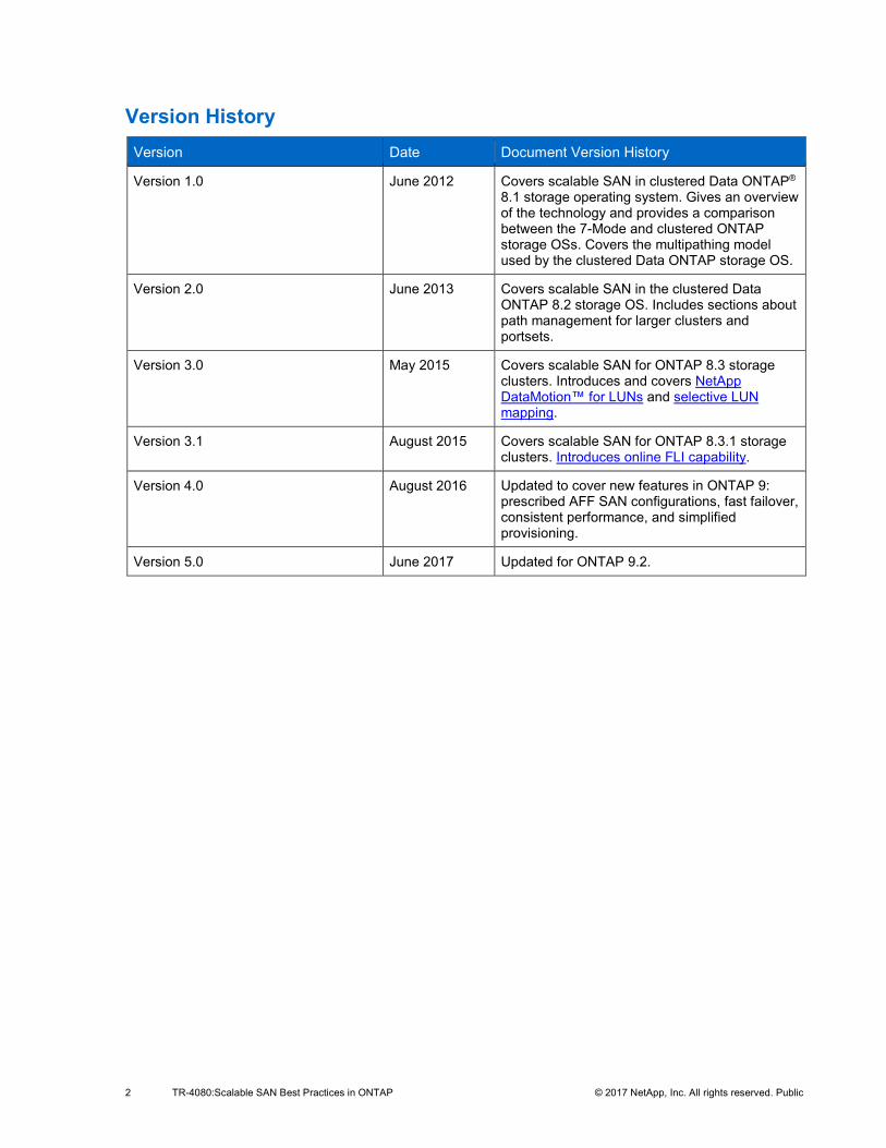
Version History Version Date Document Version History
Version 1.0 June 2012 Covers scalable SAN in clustered Data ONTAP® 8.1 storage operating system. Gives an overview of the technology and provides a comparison between the 7-Mode and clustered ONTAP storage OSs. Covers the multipathing model used by the clustered Data ONTAP storage OS.
Version 2.0 June 2013 Covers scalable SAN in the clustered Data ONTAP 8.2 storage OS. Includes sections about path management for larger clusters and portsets.
Version 3.0 May 2015 Covers scalable SAN for ONTAP 8.3 storage clusters. Introduces and covers NetApp DataMotion™ for LUNs and selective LUN mapping.
Version 3.1 August 2015 Covers scalable SAN for ONTAP 8.3.1 storage clusters. Introduces online FLI capability.
Version 4.0 August 2016 Updated to cover new features in ONTAP 9: prescribed AFF SAN configurations, fast failover, consistent performance, and simplified provisioning.
Version 5.0 June 2017 Updated for ONTAP 9.2.
3 TR-4080:Scalable SAN Best Practices in ONTAP © 2017 NetApp, Inc. All rights reserved. Public
TABLE OF CONTENTS
Version History ........................................................................................................................................... 2
1 Overview ................................................................................................................................................ 6 1.1 Audience .........................................................................................................................................................6 1.2 Caveats ...........................................................................................................................................................6
2 ONTAP 9 New Features ........................................................................................................................ 6 2.1 Prescribed AFF SAN Configurations ...............................................................................................................7 2.2 Fast Failover ...................................................................................................................................................7 2.3 Simplified Provisioning Workflows ..................................................................................................................8 2.4 Performance Capacity ....................................................................................................................................8 2.5 Low-Latency Consistent Performance ............................................................................................................9 2.6 igroup Ping ......................................................................................................................................................9 2.7 Intercluster Copy Offload ................................................................................................................................9 2.8 SAN Performance Improvements ...................................................................................................................9
3 ONTAP 9.1 New Features ..................................................................................................................... 9 3.1 12-Node SAN ................................................................................................................................................ 10 3.2 SAP HANA .................................................................................................................................................... 10 3.3 AFF FLI support ............................................................................................................................................ 10 3.4 32GB FC Target ............................................................................................................................................ 10
4 ONTAP 9.2 New Features ................................................................................................................... 10 4.1 ONTAP 9.2 SAN-Specific Features .............................................................................................................. 10 i) 32GBps End-to-End Support ........................................................................................................................ 10 ii) 8-Node SAN MetroCluster GA ...................................................................................................................... 10 iii) iSCSI Access Control .................................................................................................................................... 10 4.2 ONTAP 9.2 Non-SAN-Specific Features ....................................................................................................... 11 iv) Minimum QoS ............................................................................................................................................... 11 v) Balanced Placement ..................................................................................................................................... 11 4.3 Application Aware Data Management ........................................................................................................... 11
5 Clustered ONTAP and SAN Protocols .............................................................................................. 16 5.1 Clustered ONTAP Overview ......................................................................................................................... 16 5.2 Scalable SAN ................................................................................................................................................ 16 5.3 Volume Configuration ................................................................................................................................... 16 5.4 Host Connectivity .......................................................................................................................................... 17
4 TR-4080:Scalable SAN Best Practices in ONTAP © 2017 NetApp, Inc. All rights reserved. Public
5.5 Path Selection ............................................................................................................................................... 17 5.6 Path Selection Changes ............................................................................................................................... 18 vi) HA Failover ................................................................................................................................................... 18 vii) Port or Switch Failure .................................................................................................................................... 19 viii) Volume or LUN Mobility ................................................................................................................................ 19 5.7 Fibre Channel and NPIV ............................................................................................................................... 20 5.8 Path Management and Selective LUN Mapping ........................................................................................... 23 5.9 Selective LUN Mapping ................................................................................................................................ 23 5.10 Portsets ......................................................................................................................................................... 24 5.11 Management Interfaces ................................................................................................................................ 24 5.12 DataMotion for LUNs .................................................................................................................................... 26 ix) LUN Move and LUN Copy Comparison ........................................................................................................ 26 x) Storage Efficiency Considerations ................................................................................................................ 26 xi) Data Protection Considerations .................................................................................................................... 26 xii) Scalability and Throughput Considerations ................................................................................................... 27 xiii) Data Management and Workflow Considerations ......................................................................................... 27 xiv) DataMotion and Selective LUN Mapping: Discovering and Discarding Paths ............................................... 28 5.13 Path Management Best Practices ................................................................................................................. 28
6 Scalable SAN Key Value Propositions and Features ...................................................................... 29 6.1 SVM as Unified Target and Unit of Management .......................................................................................... 29 6.2 Scalability at the Node and Cluster Levels .................................................................................................... 30 6.3 Cluster-Wide Consistency Groups ................................................................................................................ 30 6.4 Intracluster LUN and LIF Mobility .................................................................................................................. 30 6.5 Foreign LUN Import (FLI) .............................................................................................................................. 31
7 Host Integration .................................................................................................................................. 31 7.1 NetApp Host Utilities Kit ................................................................................................................................ 31 7.2 Microsoft Windows ........................................................................................................................................ 32 xv) Microsoft Windows and Native MPIO ............................................................................................................ 32 xvi) Microsoft Windows and Data ONTAP DSM .................................................................................................. 34 xvii) Host Utilities Kit ............................................................................................................................................. 34 7.3 UNIX or Linux ................................................................................................................................................ 35 xviii) Host Utilities Kit ............................................................................................................................................. 35 xix) NetApp SnapDrive ........................................................................................................................................ 35 xx) IBM AIX and Clustered ONTAP .................................................................................................................... 36 7.4 Cross-Platform Utilities ................................................................................................................................. 36
5 TR-4080:Scalable SAN Best Practices in ONTAP © 2017 NetApp, Inc. All rights reserved. Public
xxi) RBAC User Creator ...................................................................................................................................... 36
8 Summary of Best Practices ............................................................................................................... 36
Additional Resources ............................................................................................................................... 37
9 Acknowledgements ............................................................................................................................ 37
10 Contact Us ........................................................................................................................................... 37
LIST OF TABLES Table 1) Fast failover takeover and giveback timing guidelines. ....................................................................................7 Table 2) Application Aware Data Management performance tiers. .............................................................................. 12 Table 3) Scalability in ONTAP. ..................................................................................................................................... 30
LIST OF FIGURES Figure 1) Performance capacity showing performance capacity used and optimal point. ..............................................8 Figure 2) ONTAP continuous performance improvements. ............................................................................................9 Figure 3) iSCSI Access Control CLI commands. .......................................................................................................... 11 Figure 4) Application Aware Data Management initial screen. ..................................................................................... 13 Figure 5) OnCommand System Manager Basic Application Provisioning. ................................................................... 14 Figure 6) OnCommand System Manager App DM Initial screen. ................................................................................. 14 Figure 7) OnCommand System Manager Application Aware Data Management VMware. .......................................... 15 Figure 8) Overview of paths in clustered ONTAP. ........................................................................................................ 18 Figure 9) Paths during HA failover. .............................................................................................................................. 19 Figure 10) Paths during port or switch failure. .............................................................................................................. 19 Figure 11) Paths during volume or LUN mobility. ......................................................................................................... 19 Figure 12) Paths after volume or LUN mobility. ............................................................................................................ 20 Figure 13) FC adapters in System Manager. ................................................................................................................ 22 Figure 14) Network interfaces in System Manager. ...................................................................................................... 22 Figure 15) Creating a management LIF during SVM creation. ..................................................................................... 25 Figure 16) Creating a management LIF for an existing SVM........................................................................................ 25 Figure 17) Management LIF details. ............................................................................................................................. 25 Figure 18) MPIO properties in Windows 2012. ............................................................................................................. 32 Figure 19) Connecting with multipath in Windows iSCSI initiator. ................................................................................ 33 Figure 20) Multiple target ports in Windows iSCSI initiator. .......................................................................................... 33 Figure 21) Data ONTAP DSM. .................................................................................................................................... 34
6 TR-4080:Scalable SAN Best Practices in ONTAP © 2017 NetApp, Inc. All rights reserved. Public
1 Overview The NetApp ONTAP 9.2 storage operating system (storage OS) is the sixth clustered ONTAP major release to support SAN protocols after their introduction in 8.1. This paper presents an overview of clustered SAN implementations from the point of view of SAN-attached hosts. It covers new features added since 8.3.x and describes using prescribed AFF SAN configurations to optimize performance. Additionally, it describes best practices for leveraging the high-availability and data mobility features of the ONTAP storage OS.
1.1 Audience This paper is intended for system and storage architects who design iSCSI, Fibre Channel (FC), and Fibre Channel over Ethernet (FCoE) solutions with NetApp storage solutions running ONTAP 8.3.x or later. It assumes that the reader:
• Has a general knowledge of NetApp hardware and software solutions • Is familiar with block-access protocols such as Fibre Channel and iSCSI
1.2 Caveats This document is not meant to be a general introduction to ONTAP administration. An introduction is covered by the ONTAP® 9 System Administration Reference and the ONTAP® 9 SAN Administration Guide . SAN-related limits for Data ONTAP clusters that use SAN protocols can be found in the ONTAP 9 SAN Configuration Guide.
For the regularly updated and complete matrix of tested and supported SAN configurations, refer to the Interoperability Matrix Tool (IMT) on the NetApp Support site to validate that the exact product and feature versions described in this document are supported for your specific environment. The NetApp IMT defines the product components and versions that have been tested together and qualified by NetApp to work together. Specific results depend on each customer's installation in accordance with published specifications.
2 ONTAP 9 New Features ONTAP 9 has several new SAN-related features, some of which are mostly invisible to storage administrators, architects, and users, and some of which are not. Some of the features that are not readily visible include:
• Cluster hardening.
• Improvements in quorum handling, including several autoheal features.
• Enhancements to first failure detection and reliability, availability, and serviceability (RAS).
• Foreign LUN import (FLI) to verify performance improvements. The imported LUN verification workflow has some performance improvements that allow verifications to complete more rapidly.
• Foreign LUN import hardening. There has been some hardening in FLI to allow imports to survive and be restarted after a takeover or giveback, an event that previously would have required a restart of the import.
These enhancements fall into two primary categories:
• Hardening and resiliency. These are enhancements made to ONTAP code to make ONTAP more resilient in the face of faults. In many cases ONTAP can encounter a fault and heal itself without any human intervention.
• RAS. These enhancements are primarily categorized around creating messaging and gathering appropriate counters so that faults are more easily isolated, recognized, and diagnosed. This allows
7 TR-4080:Scalable SAN Best Practices in ONTAP © 2017 NetApp, Inc. All rights reserved. Public
storage administrators and NetApp support to more quickly diagnose and resolve fault conditions, often before there is any externally recognizable impact.
Additional features that are noticeable and likely to be compelling to storage architects, professional services, and storage administrators include: • Prescribed All Flash FAS (AFF) SAN configurations • Fast failover • Out-of-box experience • Simplified provisioning workflows • Performance capacity • Low-latency consistent performance • igroup ping • Intercluster copy offload • SAN performance improvements These features are described in the following sections. For an overview of all the product enhancements in ONTAP 9, review the release notes for ONTAP 9.
2.1 Prescribed AFF SAN Configurations Customers who elect to use prescribed All Flash FAS SAN configuration limits and configurations are guaranteed consistent low-latency operations and fast failover. The prescribed AFF SAN configurations are described in detail in TR-4480: All Flash FAS SAN Optimized Configuration. By staying within the prescriptions outlined in TR-4480, storage professionals are able to optimize SAN performance, making sure of consistent low-latency performance with fast failover and givebacks. This is enabled by staying within a certain number of objects and selecting certain configuration items. By doing this, administrators see latencies below 1ms, with failovers and givebacks occurring within 2 to 10 seconds for planned failovers and givebacks and 2 to 15 seconds for unplanned failovers and givebacks. For detailed information about the prescribed configuration requirements and settings, review TR-4480: All Flash FAS SAN Optimized Configuration.
2.2 Fast Failover ONTAP 9 continues code optimizations and enhancements that have reduced the time ONTAP HA pairs require to take over and give back partner workloads. When operating in an AFF prescribed SAN configuration, planned takeovers and givebacks complete within 2 to 10 seconds. Unplanned takeovers and givebacks complete within 2 to 15 seconds. Both of these measurements are the time it takes for one node of the HA pair to fail over or give back from the other node in the HA pair. In testing, most operating system stacks resumed I/O from 4 to 7 seconds after the takeover or giveback event started. This is a fairly dramatic improvement over ONTAP 8.3.x takeover/giveback performance, where the respective numbers for takeover/giveback completions for planned and unplanned on AFF prescribed configurations were within approximately 15 to 30 seconds. Table 1 summarizes the failover times by platform type and version of ONTAP. All the numbers assume that the HA pairs are in a prescribed SAN configuration as defined by TR-4515: AFF SAN Best Practices for Business Critical Workloads.
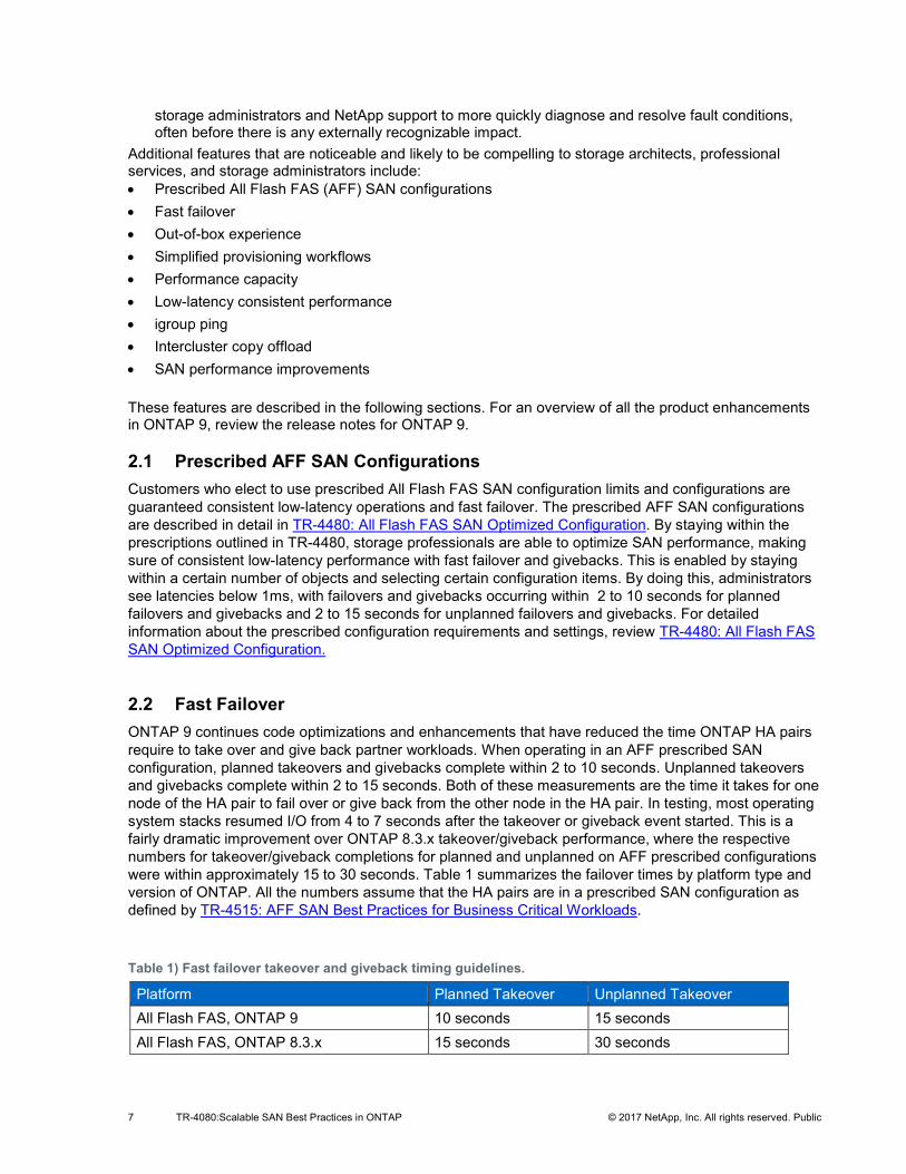
Table 1) Fast failover takeover and giveback timing guidelines.
Platform Planned Takeover Unplanned Takeover All Flash FAS, ONTAP 9 10 seconds 15 seconds All Flash FAS, ONTAP 8.3.x 15 seconds 30 seconds
8 TR-4080:Scalable SAN Best Practices in ONTAP © 2017 NetApp, Inc. All rights reserved. Public
Platform Planned Takeover Unplanned Takeover FAS with Flash Pool™ or SSD aggregates 30 seconds 60 seconds
Note: FAS systems using FlexArray® do not have an associated takeover and giveback timing guideline.
2.3 Simplified Provisioning Workflows The simplified provisioning workflows introduced in ONTAP 9 have been improved dramatically and are now part of the Application Aware Data Management workflows, covered in section 4.3 Application Aware Data Management.
2.4 Performance Capacity Performance capacity is a new feature that uses counter manager statistics gathered by the controller, which are then consumed by OnCommand® Performance Manager (OPM) to analyze performance counters to dynamically optimize for the maximum IOPS that can be produced while maintaining consistent low latency. This means that storage administrators no longer have to guess whether there is sufficient remaining performance potential on a controller or HA pair to add additional workloads.
In an All Flash FAS SAN business-critical configuration, OPM can use the ONTAP generated performance capacity calculations to maximize IOPS while maintaining <1ms latencies. Latencies may be somewhat higher when there is a failover; obviously, this needs to be taken into account in workload planning.
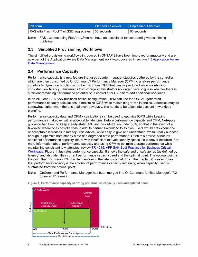
Performance capacity data and OPM visualizations can be used to optimize IOPS while keeping performance in takeover within acceptable latencies. Before performance capacity and OPM, NetApp’s guidance had been to keep steady-state CPU and disk utilization under 50%, so that in the event of a takeover, where one controller has to add its partner’s workload to its own, users would not experience unacceptable increases in latency. This advice, while easy to give and understand, wasn’t really nuanced enough to optimize both steady-state and degraded-state performance. Often this advice either left additional performance capacity idle or was insufficient to avoid latency spikes if a takeover occurred. For more information about performance capacity and using OPM to optimize storage performance while maintaining consistent low latencies, review TR-4515: AFF SAN Best Practices for Business Critical Workloads. Figure 1 illustrates performance capacity. It shows the safe and unsafe zones (as defined by latency) and also identifies current performance capacity used and the optimal point. The optimal point is the point that maximizes IOPS while maintaining the latency target. From the graphic, it is easy to see that performance capacity is the amount of performance capacity remaining when capacity used is subtracted from the optimal point.
Note: OnCommand Performance Manager has been merged into OnCommand Unified Manager’s 7.2 (June 2017 release).
Figure 1) Performance capacity showing performance capacity used and optimal point.
9 TR-4080:Scalable SAN Best Practices in ONTAP © 2017 NetApp, Inc. All rights reserved. Public
2.5 Low-Latency Consistent Performance ONTAP 9 is able to achieve and guarantee consistent low-latency performance when AFF prescriptive SAN configuration guidelines are followed in conjunction with using performance capacity and OPM. For more information about prescriptive SAN configurations and using performance capacity and OPM, review TR-4515: AFF SAN Best Practices for Business Critical Workloads.
2.6 igroup Ping igroup ping is a new enhancement offered in ONTAP 9 that allows the storage admin to verify that members of an FC igroup are able to access mapped LUNs through the LIFs identified by the igroup. This is done by using FC ping.
2.7 Intercluster Copy Offload This feature of ONTAP 9 allows Windows to nondisruptively offload copying blocks between LUNs, which significantly reduces CPU load, network bandwidth, and move durations, while maintaining access to the LUNs, which remain online throughout the move. This feature is an extension of Microsoft Windows Server 2012’s copy offload feature (ODX). In SAN, it is supported only with Windows LUNs.
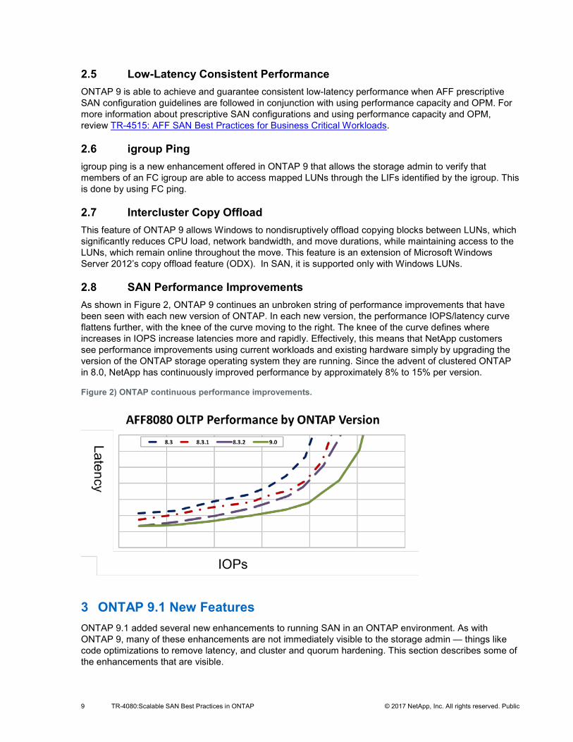
2.8 SAN Performance Improvements As shown in Figure 2, ONTAP 9 continues an unbroken string of performance improvements that have been seen with each new version of ONTAP. In each new version, the performance IOPS/latency curve flattens further, with the knee of the curve moving to the right. The knee of the curve defines where increases in IOPS increase latencies more and rapidly. Effectively, this means that NetApp customers see performance improvements using current workloads and existing hardware simply by upgrading the version of the ONTAP storage operating system they are running. Since the advent of clustered ONTAP in 8.0, NetApp has continuously improved performance by approximately 8% to 15% per version.
Figure 2) ONTAP continuous performance improvements.
3 ONTAP 9.1 New Features ONTAP 9.1 added several new enhancements to running SAN in an ONTAP environment. As with ONTAP 9, many of these enhancements are not immediately visible to the storage admin — things like code optimizations to remove latency, and cluster and quorum hardening. This section describes some of the enhancements that are visible.
10 TR-4080:Scalable SAN Best Practices in ONTAP © 2017 NetApp, Inc. All rights reserved. Public
3.1 12-Node SAN ONTAP 9.1 increased the maximum diameter of an ONTAP SAN from 8 nodes to 12 nodes. Although the number of nodes increased by 50%, the maximum number of LUNs the cluster supports remained the same, at 98,304 LUNs. This means that if all nodes were using the maximum, the maximum number of LUNs per node would go from 12,288 to 8,192 LUNs on each of the 12 controllers.
3.2 SAP HANA A SAP HANA workflow was added to the simplified provisioning workflows that can be run from OnCommand System Manager.
3.3 AFF Foreign LUN Import support Before ONTAP 9.1, AFF did not support foreign LUN import (FLI) natively. To use FLI with AFF as the destination, the account team had to file a Product Variance Request (PVR). Once the request was approved, an approval letter was sent detailing commands that needed to be performed to enable FLI support on AFF. With ONTAP 9.1, this is no longer necessary because AFF now has FLI support enabled.
3.4 32GB FC Target ONTAP 9.1 debuts a 32GB Fibre Channel target, which increases the bandwidth available and also ensures that there will be adequate bandwidth for the growing densities seen in the number of LIFs associated with physical Fibre Channel ports in NetApp controllers.
4 ONTAP 9.2 New Features ONTAP 9.2 adds several new features. As was the case with ONTAP 9 and 9.1, some of these features include a considerable amount of content that is largely invisible to the storage administrator or consumer. These features include a substantial investment in code review and optimizations to increase performance and to harden the cluster, underlying components, and quorum maintenance. Some enhancements that are visible will improve the storage admin's provisioning and management experience. Some of these enhancements are SAN-specific, and some are not SAN-specific but have substantial effects on provisioning, managing, and optimizing block protocol storage in ONTAP 9.2. The following subsections describe those enhancements, starting with the SAN-specific features, followed by discussions of other enhancements that substantially improve the NetApp SAN experience.
4.1 ONTAP 9.2 SAN-Specific Features 1. 32GBps End-to-End Support With ONTAP 9.2, NetApp adds end-to-end support for 32GB Fibre Channel. This support includes 32GB target adapters, either onboard with some of the newer controllers like the A Series of All Flash FAS, FAS 8200, and FAS 9000 series controllers or as expansion cards. Additionally, NetApp has added 32GB FC target expansion cards. NetApp also resells 32GB switches and 32GB host bus adapters (initiators)
2. 8-Node SAN MetroCluster GA ONTAP 9.2 now includes support for 8-node SAN MetroCluster™ high-availability and disaster recovery software.
3. iSCSI Access Control
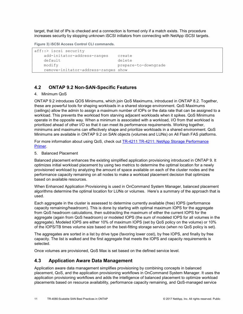
ONTAP 9.2 introduces iSCSI access control, which allows administrators to use an access control list in addition to LUN masking (igroups) and CHAP to gate iSCSI connection setups. iSCSI endpoint security is defined from the command line interface on a cluster node, making it possible to supply a list of IP addresses or a range of addresses. When an iSCSI initiator attempts to connect to the NetApp iSCSI
11 TR-4080:Scalable SAN Best Practices in ONTAP © 2017 NetApp, Inc. All rights reserved. Public
target, that list of IPs is checked and a connection is formed only if a match exists. This procedure increases security by stopping unknown iSCSI initiators from connecting with NetApp iSCSI targets.
Figure 3) iSCSI Access Control CLI commands.
aff::> iscsi security add-initator-address-ranges create default delete modify prepare-to-downgrade remove-initator-address-ranges show
4.2 ONTAP 9.2 Non-SAN-Specific Features 4. Minimum QoS
ONTAP 9.2 introduces QOS Minimums, which join QoS Maximums, introduced in ONTAP 8.2. Together, these are powerful tools for shaping workloads in a shared storage environment. QoS Maximums (ceilings) allow the admin to assign a maximum number of IOPs or the data rate that can be assigned to a workload. This prevents the workload from starving adjacent workloads when it spikes. QoS Minimums operate in the opposite way. When a minimum is associated with a workload, I/O from that workload is prioritized ahead of other I/O so that it can meet its performance requirements. Working together, minimums and maximums can effectively shape and prioritize workloads in a shared environment. QoS Minimums are available in ONTAP 9.2 on SAN objects (volumes and LUNs) on All Flash FAS platforms.
For more information about using QoS, check out TR-4211 TR-4211: NetApp Storage Performance Primer.
5. Balanced Placement
Balanced placement enhances the existing simplified application provisioning introduced in ONTAP 9. It optimizes initial workload placement by using two metrics to determine the optimal location for a newly provisioned workload by analyzing the amount of space available on each of the cluster nodes and the performance capacity remaining on all nodes to make a workload placement decision that optimizes based on available resources.
When Enhanced Application Provisioning is used in OnCommand System Manager, balanced placement algorithms determine the optimal location for LUNs or volumes. Here’s a summary of the approach that is used.
Each aggregate in the cluster is assessed to determine currently available (free) IOPS (performance capacity remaining/headroom). This is done by starting with optimal maximum IOPS for the aggregate from QoS headroom calculations, then subtracting the maximum of either the current IOPS for the aggregate (again from QoS headroom) or modeled IOPS (the sum of modeled IOPS for all volumes in the aggregate). Modeled IOPS are either 10% of maximum IOPS (set by QoS policy on the volume) or 10% of the IOPS/TB times volume size based on the best-fitting storage service (when no QoS policy is set).
The aggregates are sorted in a list by drive type (favoring lower cost), by free IOPS, and finally by free capacity. The list is walked and the first aggregate that meets the IOPS and capacity requirements is selected.
Once volumes are provisioned, QoS Max is set based on the defined service level.
4.3 Application Aware Data Management Application aware data management simplifies provisioning by combining concepts in balanced placement, QoS, and the application provisioning workflows in OnCommand System Manager. It uses the application provisioning workflows and adds the intelligence of balanced placement to optimize workload placements based on resource availability, performance capacity remaining, and QoS-managed service
12 TR-4080:Scalable SAN Best Practices in ONTAP © 2017 NetApp, Inc. All rights reserved. Public
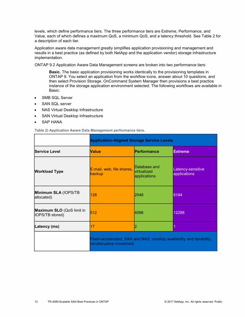
levels, which define performance tiers. The three performance tiers are Extreme, Performance, and Value, each of which defines a maximum QoS, a minimum QoS, and a latency threshold. See Table 2 for a description of each tier.
Application aware data management greatly simplifies application provisioning and management and results in a best practice (as defined by both NetApp and the application vendor) storage infrastructure implementation.
ONTAP 9.2 Application Aware Data Management screens are broken into two performance tiers:
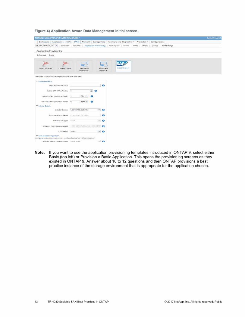
Basic. The basic application provisioning works identically to the provisioning templates in ONTAP 9. You select an application from the workflow icons, answer about 10 questions, and then select Provision Storage. OnCommand System Manager then provisions a best practice instance of the storage application environment selected. The following workflows are available in Basic:
• SMB SQL Server • SAN SQL server • NAS Virtual Desktop Infrastructure • SAN Virtual Desktop Infrastructure • SAP HANA
Table 2) Application Aware Data Management performance tiers.
Application-Aligned Storage Service Levels
Service Level Value Performance Extreme
Workload Type E-mail, web, file shares, backup
Database and virtualized applications
Latency-sensitive applications
Minimum SLA (IOPS/TB allocated) 128 2048 6144
Maximum SLO (QoS limit in IOPS/TB stored) 512 4096 12288
Latency (ms) 17 2 1
Flash-accelerated, SAN and NAS, nonstop availability and durability, nondisruptive movement
13 TR-4080:Scalable SAN Best Practices in ONTAP © 2017 NetApp, Inc. All rights reserved. Public
Figure 4) Application Aware Data Management initial screen.
Note: If you want to use the application provisioning templates introduced in ONTAP 9, select either Basic (top left) or Provision a Basic Application. This opens the provisioning screens as they existed in ONTAP 9. Answer about 10 to 12 questions and then ONTAP provisions a best practice instance of the storage environment that is appropriate for the application chosen.
14 TR-4080:Scalable SAN Best Practices in ONTAP © 2017 NetApp, Inc. All rights reserved. Public
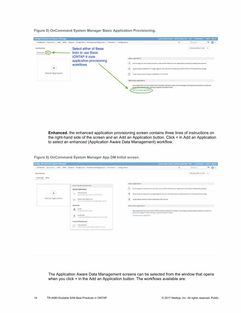
Figure 5) OnCommand System Manager Basic Application Provisioning.
Enhanced. the enhanced application provisioning screen contains three lines of instructions on the right-hand side of the screen and an Add an Application button. Click + in Add an Application to select an enhanced (Application Aware Data Management) workflow.
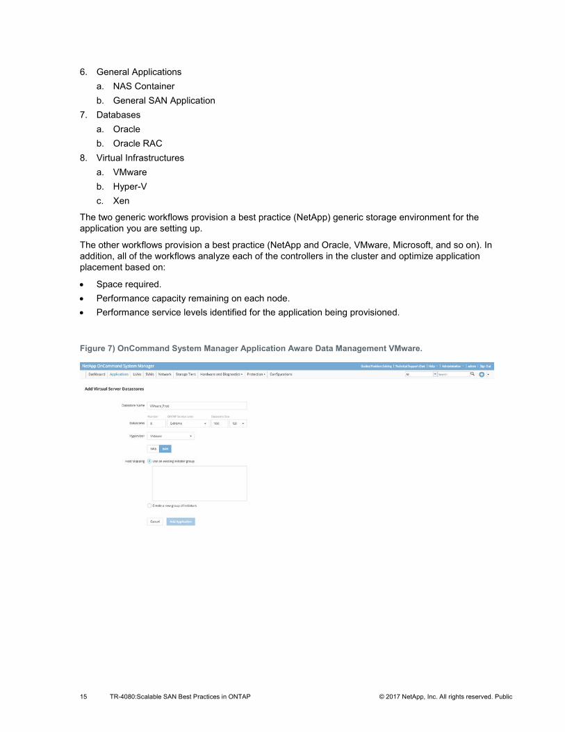
Figure 6) OnCommand System Manager App DM Initial screen.
The Application Aware Data Management screens can be selected from the window that opens when you click + in the Add an Application button. The workflows available are:
15 TR-4080:Scalable SAN Best Practices in ONTAP © 2017 NetApp, Inc. All rights reserved. Public
6. General Applications a. NAS Container b. General SAN Application
7. Databases a. Oracle b. Oracle RAC
8. Virtual Infrastructures a. VMware b. Hyper-V c. Xen
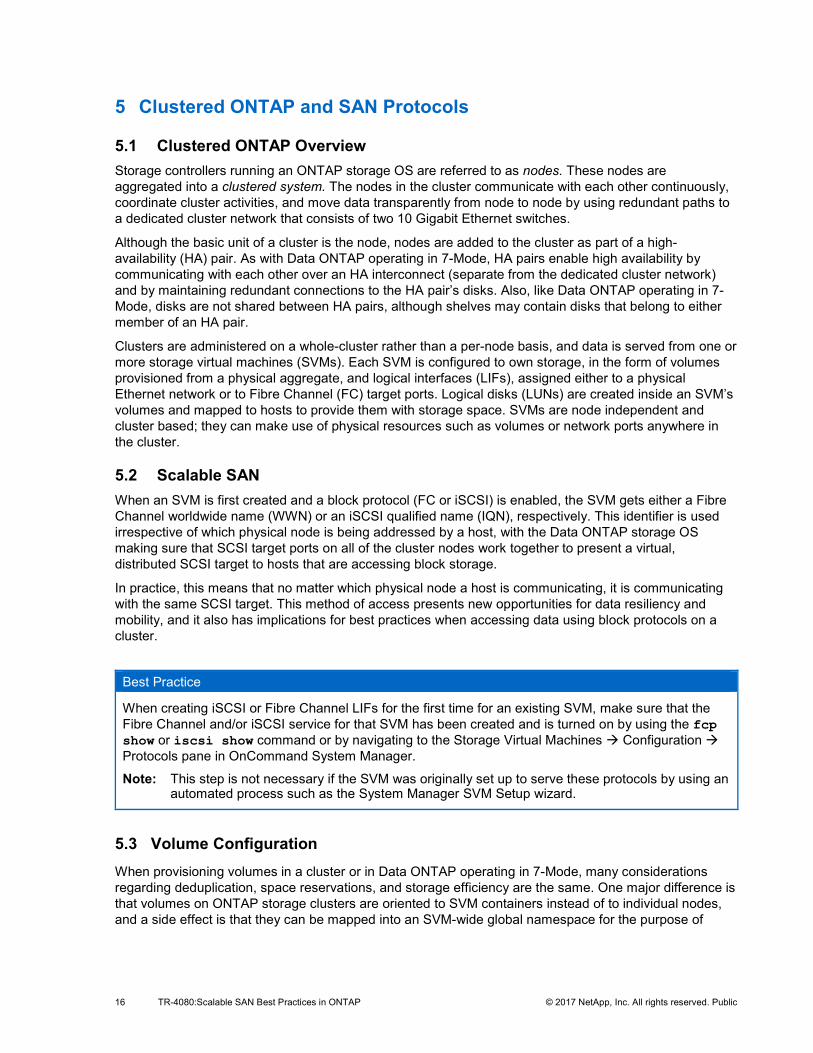
The two generic workflows provision a best practice (NetApp) generic storage environment for the application you are setting up.
The other workflows provision a best practice (NetApp and Oracle, VMware, Microsoft, and so on). In addition, all of the workflows analyze each of the controllers in the cluster and optimize application placement based on:
• Space required. • Performance capacity remaining on each node. • Performance service levels identified for the application being provisioned.
Figure 7) OnCommand System Manager Application Aware Data Management VMware.
16 TR-4080:Scalable SAN Best Practices in ONTAP © 2017 NetApp, Inc. All rights reserved. Public
5 Clustered ONTAP and SAN Protocols
5.1 Clustered ONTAP Overview Storage controllers running an ONTAP storage OS are referred to as nodes. These nodes are aggregated into a clustered system. The nodes in the cluster communicate with each other continuously, coordinate cluster activities, and move data transparently from node to node by using redundant paths to a dedicated cluster network that consists of two 10 Gigabit Ethernet switches.
Although the basic unit of a cluster is the node, nodes are added to the cluster as part of a high-availability (HA) pair. As with Data ONTAP operating in 7-Mode, HA pairs enable high availability by communicating with each other over an HA interconnect (separate from the dedicated cluster network) and by maintaining redundant connections to the HA pair’s disks. Also, like Data ONTAP operating in 7-Mode, disks are not shared between HA pairs, although shelves may contain disks that belong to either member of an HA pair.
Clusters are administered on a whole-cluster rather than a per-node basis, and data is served from one or more storage virtual machines (SVMs). Each SVM is configured to own storage, in the form of volumes provisioned from a physical aggregate, and logical interfaces (LIFs), assigned either to a physical Ethernet network or to Fibre Channel (FC) target ports. Logical disks (LUNs) are created inside an SVM’s volumes and mapped to hosts to provide them with storage space. SVMs are node independent and cluster based; they can make use of physical resources such as volumes or network ports anywhere in the cluster.
5.2 Scalable SAN When an SVM is first created and a block protocol (FC or iSCSI) is enabled, the SVM gets either a Fibre Channel worldwide name (WWN) or an iSCSI qualified name (IQN), respectively. This identifier is used irrespective of which physical node is being addressed by a host, with the Data ONTAP storage OS making sure that SCSI target ports on all of the cluster nodes work together to present a virtual, distributed SCSI target to hosts that are accessing block storage.
In practice, this means that no matter which physical node a host is communicating, it is communicating with the same SCSI target. This method of access presents new opportunities for data resiliency and mobility, and it also has implications for best practices when accessing data using block protocols on a cluster.
Best Practice
When creating iSCSI or Fibre Channel LIFs for the first time for an existing SVM, make sure that the Fibre Channel and/or iSCSI service for that SVM has been created and is turned on by using the fcp show or iscsi show command or by navigating to the Storage Virtual Machines Æ Configuration Æ Protocols pane in OnCommand System Manager.
Note: This step is not necessary if the SVM was originally set up to serve these protocols by using an automated process such as the System Manager SVM Setup wizard.
5.3 Volume Configuration When provisioning volumes in a cluster or in Data ONTAP operating in 7-Mode, many considerations regarding deduplication, space reservations, and storage efficiency are the same. One major difference is that volumes on ONTAP storage clusters are oriented to SVM containers instead of to individual nodes, and a side effect is that they can be mapped into an SVM-wide global namespace for the purpose of
17 TR-4080:Scalable SAN Best Practices in ONTAP © 2017 NetApp, Inc. All rights reserved. Public
exporting file systems by using NFS or CIFS protocols. However, the presence or absence of a given volume in the global namespace has no effect on data that is served by using Fibre Channel or iSCSI.
Best Practice
Volumes that contain LUNs do not need to be junctioned to the global namespace to serve data by using block protocols; they only require an igroup-to-LUN mapping.
5.4 Host Connectivity Hosts that access data served by a clustered ONTAP storage cluster using a block protocol are expected to make use of the asymmetrical logical unit access (ALUA) extension to the SCSI protocol to determine which paths are direct and which are indirect to any particular LUN. The ALUA standard refers to direct paths as active/optimized and to indirect paths as active/nonoptimized. All ALUA information is requested and delivered in band, using the same iSCSI or Fibre Channel connection that is used for data.
The status of a given path is discoverable by a host that sends a path status inquiry down each of the paths it has discovered for a given LUN. This path status inquiry can be triggered when the storage system sends extra data along with the result of a SCSI request to inform a host that paths’ statuses have been updated and that their priorities should be rediscovered.
ALUA is a well-known and widely deployed standard and is a requirement for access to block data served by clustered ONTAP. Any operating systems tested and qualified to work with ONTAP block access protocols support ALUA.
5.5 Path Selection Even though every LIF owned by an SVM accepts writes and read requests for its LUNs, only one of the cluster nodes actually owns the disks backing that LUN at any given moment. This effectively divides available paths to a LUN into two types: direct and indirect paths.
A direct path for a LUN is a path where an SVM’s LIFs and the LUN being accessed reside on the same node. To go from a physical target port to disk, it is not necessary to traverse the cluster network.
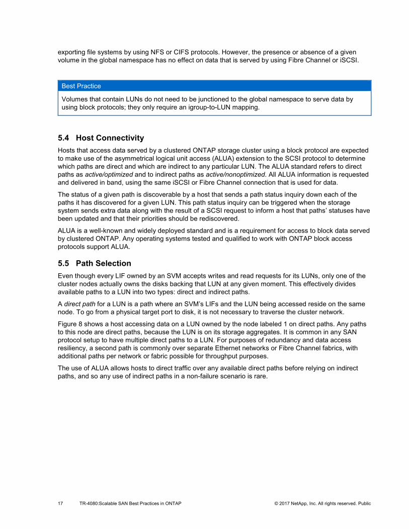
Figure 8 shows a host accessing data on a LUN owned by the node labeled 1 on direct paths. Any paths to this node are direct paths, because the LUN is on its storage aggregates. It is common in any SAN protocol setup to have multiple direct paths to a LUN. For purposes of redundancy and data access resiliency, a second path is commonly over separate Ethernet networks or Fibre Channel fabrics, with additional paths per network or fabric possible for throughput purposes.
The use of ALUA allows hosts to direct traffic over any available direct paths before relying on indirect paths, and so any use of indirect paths in a non-failure scenario is rare.
18 TR-4080:Scalable SAN Best Practices in ONTAP © 2017 NetApp, Inc. All rights reserved. Public
Figure 8) Overview of paths in clustered ONTAP.
Indirect paths are data paths where an SVM’s LIFs and the LUN being accessed reside on different nodes. Data must traverse the cluster network in order to go from a physical target port to disk. Because the cluster network is fast and highly available, this does not add a great deal of latency to the round trip, but it is not the maximally efficient data path. In a well-configured SAN environment, a host’s use of indirect paths is minimal.
Because every host communicates only with SVMs that use physical resources anywhere in the cluster, in practice this means that all connections to a cluster are managed by multipath I/O (MPIO) software running on the host that is accessing LUNs, with the result that only direct paths are used during normal operation.
Best Practice
All SVMs should be assigned LIFs on each cluster node and each Fibre Channel fabric or Ethernet network. For instance, if a four-node cluster is connected to two independent Fibre Channel fabrics, A and B, using its 3a and 4a Fibre Channel target ports, an SVM that serves data by using Fibre Channel should have eight LIFs, on node1:3a, node1:4a, node2:3a, node2:4a, node3:3a, node3:4a, node4:3a, and node4:4a. Clusters with more than four nodes should limit the number of paths used to access any given LUN for ease of manageability and in deference to operating system path count limitations. For a more in-depth discussion, see section 5.8, Path Management and Selective LUN Mapping.
For administrators who are used to using an ONTAP storage cluster with NAS protocols such as NFS and CIFS, there is a distinction to be made between LIFs that serve these protocols and LIFs that serve block iSCSI or Fibre Channel. NAS LIFs can be freely moved from node to node, or they can belong to a failover group that specifies to which node and port they move during an HA or port failover. SAN LIFs, by comparison, represent the endpoint of a number of paths, all established simultaneously between SCSI initiator and SCSI target, and the host’s MPIO software manages which paths actually receive I/O. As a result, unlike NAS LIFs, SAN LIFs do not fail over. The failover mechanism for SAN is provisioning multiple paths and using multipathing (MPIO) software on hosts to manage the multiple paths presented to them.
Because of this difference in behavior, Ethernet LIFs that serve data by using the iSCSI protocol cannot also serve data by using a NAS protocol.
5.6 Path Selection Changes There are three events that could change the path selected by a host to access data on a cluster.
HA Failover
19 TR-4080:Scalable SAN Best Practices in ONTAP © 2017 NetApp, Inc. All rights reserved. Public
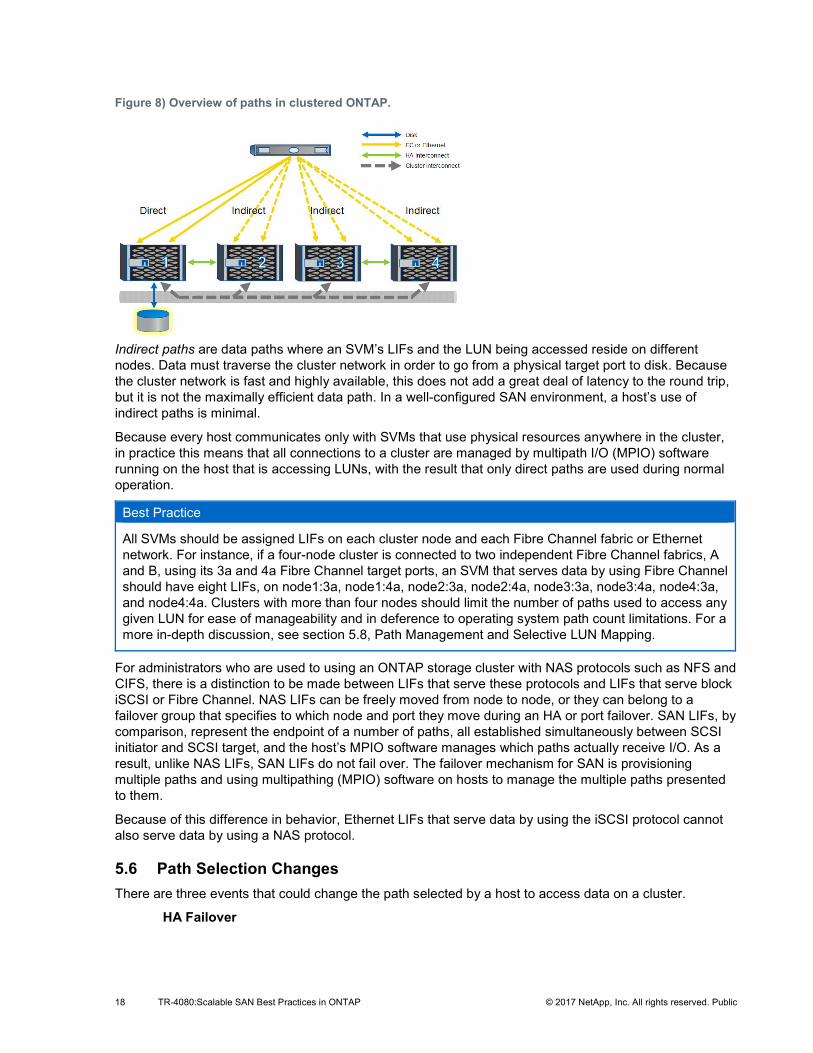
In an HA failover event, LIFs on the down node are seen as offline, and LIFs on the HA partner that has taken over for the down node are now direct paths. This state changes automatically due to ALUA path inquiry, and no administrative changes are necessary.
Figure 9) Paths during HA failover.
Port or Switch Failure In a port or switch failure, no more direct paths are available. Path priority remains the same, and MPIO software running on the host selects alternate indirect paths until a direct path becomes available again. The ALUA path states do not change.
Figure 10) Paths during port or switch failure.
Volume or LUN Mobility A volume is moved transparently between nodes by using volume move functionality, or a LUN is moved transparently between nodes using lun move.
Figure 11) Paths during volume or LUN mobility.
20 TR-4080:Scalable SAN Best Practices in ONTAP © 2017 NetApp, Inc. All rights reserved. Public
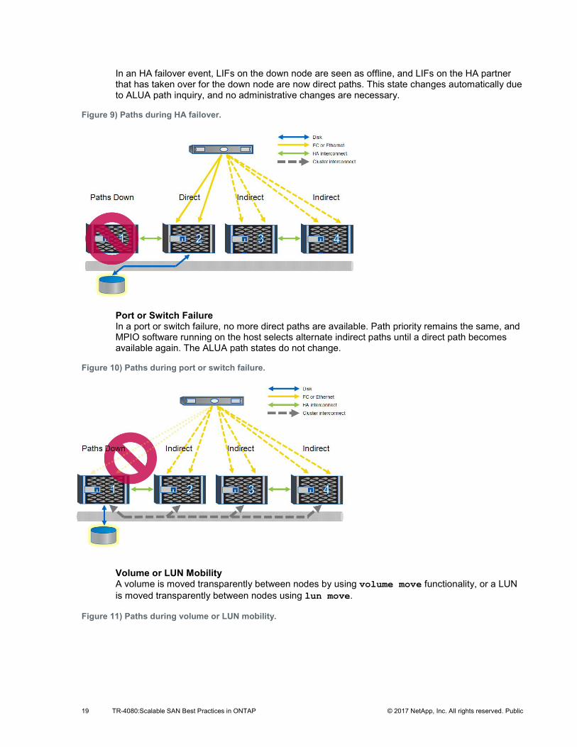
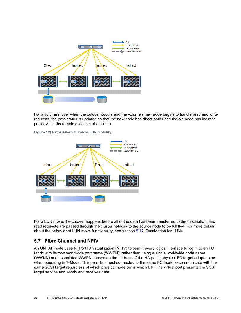
For a volume move, when the cutover occurs and the volume’s new node begins to handle read and write requests, the path status is updated so that the new node has direct paths and the old node has indirect paths. All paths remain available at all times.
Figure 12) Paths after volume or LUN mobility.
For a LUN move, the cutover happens before all of the data has been transferred to the destination, and read requests are passed through the cluster network to the source node to be fulfilled. For more details about the behavior of LUN move functionality, see section 5.12, DataMotion for LUNs.
5.7 Fibre Channel and NPIV An ONTAP node uses N_Port ID virtualization (NPIV) to permit every logical interface to log in to an FC fabric with its own worldwide port name (WWPN), rather than using a single worldwide node name (WWNN) and associated WWPNs based on the address of the HA pair’s physical FC target adapters, as when operating in 7-Mode. This permits a host connected to the same FC fabric to communicate with the same SCSI target regardless of which physical node owns which LIF. The virtual port presents the SCSI target service and sends and receives data.
21 TR-4080:Scalable SAN Best Practices in ONTAP © 2017 NetApp, Inc. All rights reserved. Public
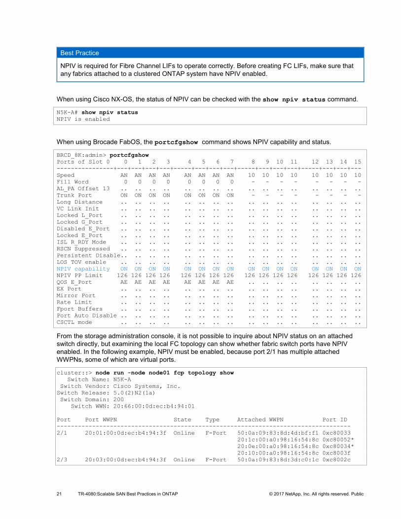
Best Practice
NPIV is required for Fibre Channel LIFs to operate correctly. Before creating FC LIFs, make sure that any fabrics attached to a clustered ONTAP system have NPIV enabled.
When using Cisco NX-OS, the status of NPIV can be checked with the show npiv status command.
N5K-A# show npiv status NPIV is enabled
When using Brocade FabOS, the portcfgshow command shows NPIV capability and status.
BRCD_8K:admin> portcfgshow Ports of Slot 0 0 1 2 3 4 5 6 7 8 9 10 11 12 13 14 15 ----------------+---+---+---+---+-----+---+---+---+-----+---+---+---+-----+---+---+--- Speed AN AN AN AN AN AN AN AN 10 10 10 10 10 10 10 10 Fill Word 0 0 0 0 0 0 0 0 - - - - - - - - AL_PA Offset 13 .. .. .. .. .. .. .. .. .. .. .. .. .. .. .. .. Trunk Port ON ON ON ON ON ON ON ON - - - - - - - - Long Distance .. .. .. .. .. .. .. .. .. .. .. .. .. .. .. .. VC Link Init .. .. .. .. .. .. .. .. .. .. .. .. .. .. .. .. Locked L_Port .. .. .. .. .. .. .. .. .. .. .. .. .. .. .. .. Locked G_Port .. .. .. .. .. .. .. .. .. .. .. .. .. .. .. .. Disabled E_Port .. .. .. .. .. .. .. .. .. .. .. .. .. .. .. .. Locked E_Port .. .. .. .. .. .. .. .. .. .. .. .. .. .. .. .. ISL R_RDY Mode .. .. .. .. .. .. .. .. .. .. .. .. .. .. .. .. RSCN Suppressed .. .. .. .. .. .. .. .. .. .. .. .. .. .. .. .. Persistent Disable.. .. .. .. .. .. .. .. .. .. .. .. .. .. .. .. LOS TOV enable .. .. .. .. .. .. .. .. .. .. .. .. .. .. .. .. NPIV capability ON ON ON ON ON ON ON ON ON ON ON ON ON ON ON ON NPIV PP Limit 126 126 126 126 126 126 126 126 126 126 126 126 126 126 126 126 QOS E_Port AE AE AE AE AE AE AE AE .. .. .. .. .. .. .. .. EX Port .. .. .. .. .. .. .. .. .. .. .. .. .. .. .. .. Mirror Port .. .. .. .. .. .. .. .. .. .. .. .. .. .. .. .. Rate Limit .. .. .. .. .. .. .. .. .. .. .. .. .. .. .. .. Fport Buffers .. .. .. .. .. .. .. .. .. .. .. .. .. .. .. .. Port Auto Disable .. .. .. .. .. .. .. .. .. .. .. .. .. .. .. .. CSCTL mode .. .. .. .. .. .. .. .. .. .. .. .. .. .. .. ..
From the storage administration console, it is not possible to inquire about NPIV status on an attached switch directly, but examining the local FC topology can show whether fabric switch ports have NPIV enabled. In the following example, NPIV must be enabled, because port 2/1 has multiple attached WWPNs, some of which are virtual ports.
cluster::> node run -node node01 fcp topology show Switch Name: N5K-A Switch Vendor: Cisco Systems, Inc. Switch Release: 5.0(2)N2(1a) Switch Domain: 200 Switch WWN: 20:66:00:0d:ec:b4:94:01 Port Port WWPN State Type Attached WWPN Port ID ----------------------------------------------------------------------------------- 2/1 20:01:00:0d:ec:b4:94:3f Online F-Port 50:0a:09:83:8d:4d:bf:f1 0xc80033 20:1c:00:a0:98:16:54:8c 0xc80052* 20:0e:00:a0:98:16:54:8c 0xc80034* 20:10:00:a0:98:16:54:8c 0xc8003f 2/3 20:03:00:0d:ec:b4:94:3f Online F-Port 50:0a:09:83:8d:3d:c0:1c 0xc8002c
22 TR-4080:Scalable SAN Best Practices in ONTAP © 2017 NetApp, Inc. All rights reserved. Public
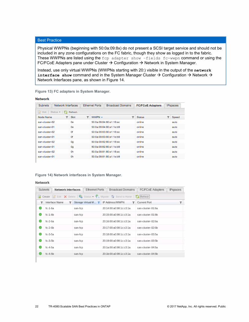
Best Practice
Physical WWPNs (beginning with 50:0a:09:8x) do not present a SCSI target service and should not be included in any zone configurations on the FC fabric, though they show as logged in to the fabric. These WWPNs are listed using the fcp adapter show –fields fc-wwpn command or using the FC/FCoE Adapters pane under Cluster Æ Configuration Æ Network in System Manager.
Instead, use only virtual WWPNs (WWPNs starting with 20:) visible in the output of the network interface show command and in the System Manager Cluster Æ Configuration Æ Network Æ Network Interfaces pane, as shown in Figure 14.
Figure 13) FC adapters in System Manager.
Figure 14) Network interfaces in System Manager.
23 TR-4080:Scalable SAN Best Practices in ONTAP © 2017 NetApp, Inc. All rights reserved. Public
5.8 Path Management and Selective LUN Mapping Clusters with more than two nodes are likely to have more paths than has commonly been the case in the past. Clusters attached to more than one fabric, or with storage controllers attached more than once per fabric, can quickly multiply the number of potential paths available.
This presents the following potential problems to the storage administrator:
• Having a large number of target ports can be good for redundancy, but it can become operationally burdensome. In an FC environment, it requires larger, more complex zones and zonesets; a larger table of WWPNs belonging to cluster SVMs of which to keep track; or, in the case of an iSCSI environment, a large number of sessions to be established for every host that requires a LUN.
• Many operating systems have an upper limit to the number of paths it is feasible for them to access. Especially for hosts that have many paths and many LUNs, this can lead to LUN enumeration or path status problems.
• Some demanding, high-throughput workloads can benefit from having their traffic segregated from less critical traffic to reduce contention, but ALUA path statuses provide no mechanism to prioritize one direct path over another.
• The ONTAP storage OS has an upper tested limit to the total number of established paths (known as an initiator-target nexus, or ITN). See the SAN Configuration Guide or the Hardware Universe site for further details about the limit for any NetApp storage controller.
You should consider limiting the total number of paths presented. However, to make sure of both a direct path to data and availability/redundancy in the case of an HA failover or path failure, at a minimum, both the node that contains the volume with the data being accessed and its HA partner must present paths.
There are two methods for limiting paths presented by a LUN by using storage OS capabilities, as opposed to limiting paths only using FC zoning or iSCSI session management: selective LUN mapping, which is enabled by default (ONTAP 8.3 and later), and portsets.
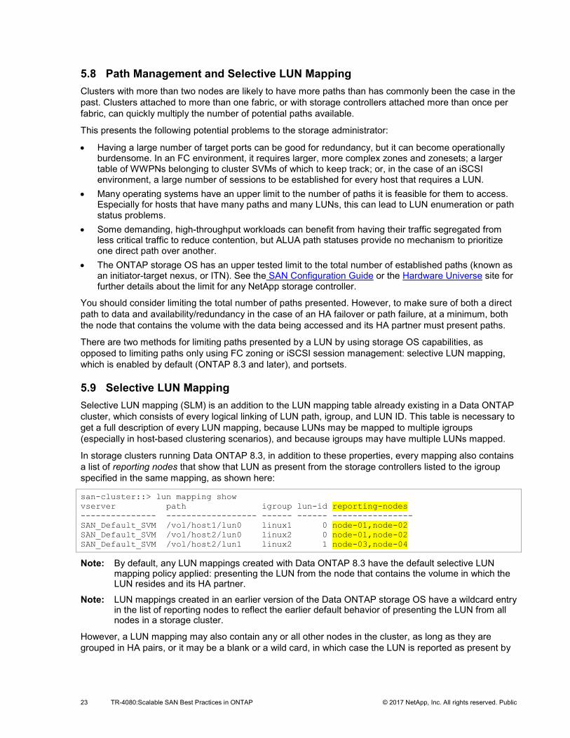
5.9 Selective LUN Mapping Selective LUN mapping (SLM) is an addition to the LUN mapping table already existing in a Data ONTAP cluster, which consists of every logical linking of LUN path, igroup, and LUN ID. This table is necessary to get a full description of every LUN mapping, because LUNs may be mapped to multiple igroups (especially in host-based clustering scenarios), and because igroups may have multiple LUNs mapped.
In storage clusters running Data ONTAP 8.3, in addition to these properties, every mapping also contains a list of reporting nodes that show that LUN as present from the storage controllers listed to the igroup specified in the same mapping, as shown here:
san-cluster::> lun mapping show vserver path igroup lun-id reporting-nodes --------------- ------------------ ------ ------ ---------------- SAN_Default_SVM /vol/host1/lun0 linux1 0 node-01,node-02 SAN_Default_SVM /vol/host2/lun0 linux2 0 node-01,node-02 SAN_Default_SVM /vol/host2/lun1 linux2 1 node-03,node-04
Note: By default, any LUN mappings created with Data ONTAP 8.3 have the default selective LUN mapping policy applied: presenting the LUN from the node that contains the volume in which the LUN resides and its HA partner.
Note: LUN mappings created in an earlier version of the Data ONTAP storage OS have a wildcard entry in the list of reporting nodes to reflect the earlier default behavior of presenting the LUN from all nodes in a storage cluster.
However, a LUN mapping may also contain any or all other nodes in the cluster, as long as they are grouped in HA pairs, or it may be a blank or a wild card, in which case the LUN is reported as present by
24 TR-4080:Scalable SAN Best Practices in ONTAP © 2017 NetApp, Inc. All rights reserved. Public
every node in the cluster. In this way, storage administrators may choose which storage controllers present paths in a highly granular fashion.
5.10 Portsets Portsets permit administrators to mask an interface group so that the LUNs that are mapped to it are available on a subset of the total number of available target ports. This functionality is available in both clustered ONTAP and 7-Mode. Whereas in clustered ONTAP 8.2 and earlier, portsets played a larger role in path management, in the Data ONTAP 8.3 storage OS they are used for the purpose of limiting the number of paths presented in a scenario where storage controllers and SVMs have more than one target LIF available per FC fabric or Ethernet network. In such cases, for example, it may be considered desirable to limit traffic for a set of hosts or for an application to a dedicated subset of the total number of target ports.
Note: A LIF that is currently a member of a portset cannot be modified until it is removed from the portset. It can be added to the portset after modification, but care should be taken to leave enough LIFs in the portset to satisfy host requirements for a path to data.
To make sure of both a direct path to data and availability/redundancy in the case of an HA failover or non-disruptive operation event, the only paths required are to the node that contains the volume with the data being accessed and its HA partner.
5.11 Management Interfaces Because LIFs belonging to SVMs that serve data by using block protocols cannot also be used for administration purposes and because the logical unit of management on an ONTAP storage cluster is the SVM, every SVM must have a management interface in addition to interfaces that are serving data using block protocols.
Best Practices
A management interface on an SVM serving block data should have the following properties:
• A LIF type of data • No data protocols assigned (-data-protocols none) • A firewall policy that permits management access (-firewall-policy mgmt) • A failover group and policy that keep the LIF accessible to hosts that might need to contact it for
data management purposes, such as creating or managing Snapshot® copies (For more information about failover groups, see “Configuring Failover Groups and Policies for LIFs” in the ONTAP Network Management Guide.)
Additionally, an SVM-level administrative account should be available. The default account created during SVM creation is the vsadmin account, but it must first be assigned a password with the security login password command and then unlocked by using the security login unlock command. For more details, see “Delegating Administration to SVM Administrators” in the ONTAP System Administration Guide.
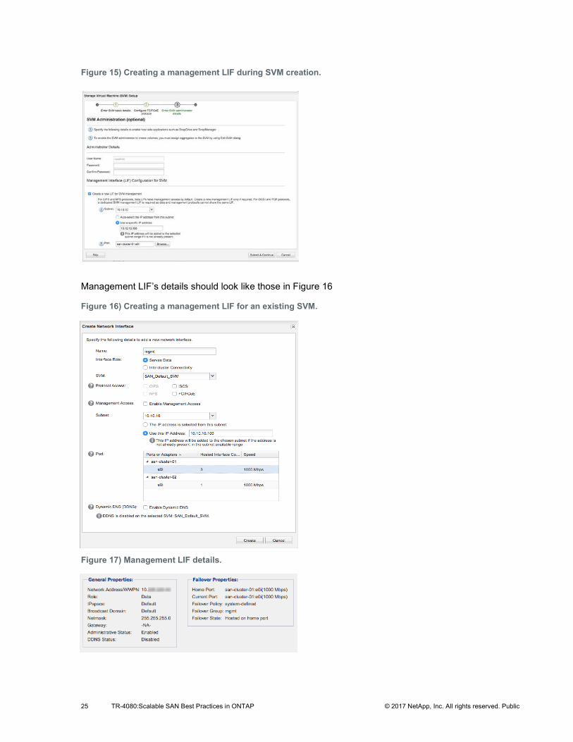
When administering a cluster using System Manager, an SVM management LIF may be created during step 3 of SVM creation, or it may be designated a management LIF during normal LIF creation. See Figures 15, 16, and 17.
25 TR-4080:Scalable SAN Best Practices in ONTAP © 2017 NetApp, Inc. All rights reserved. Public
Figure 15) Creating a management LIF during SVM creation.
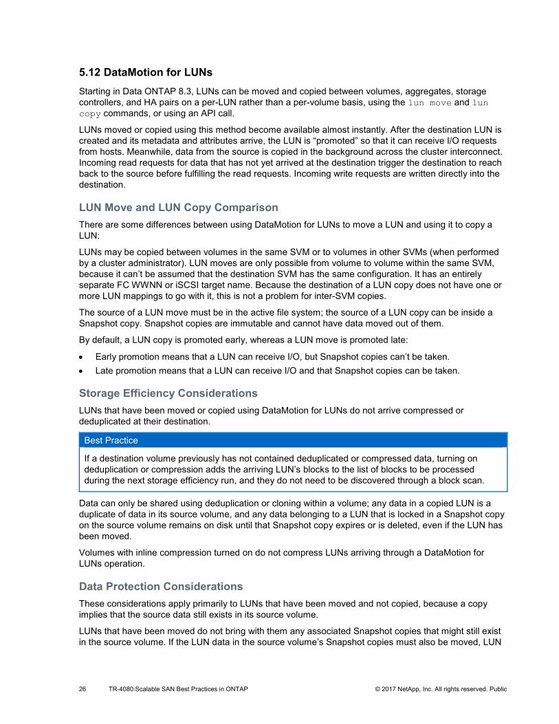
Management LIF’s details should look like those in Figure 16
Figure 16) Creating a management LIF for an existing SVM.
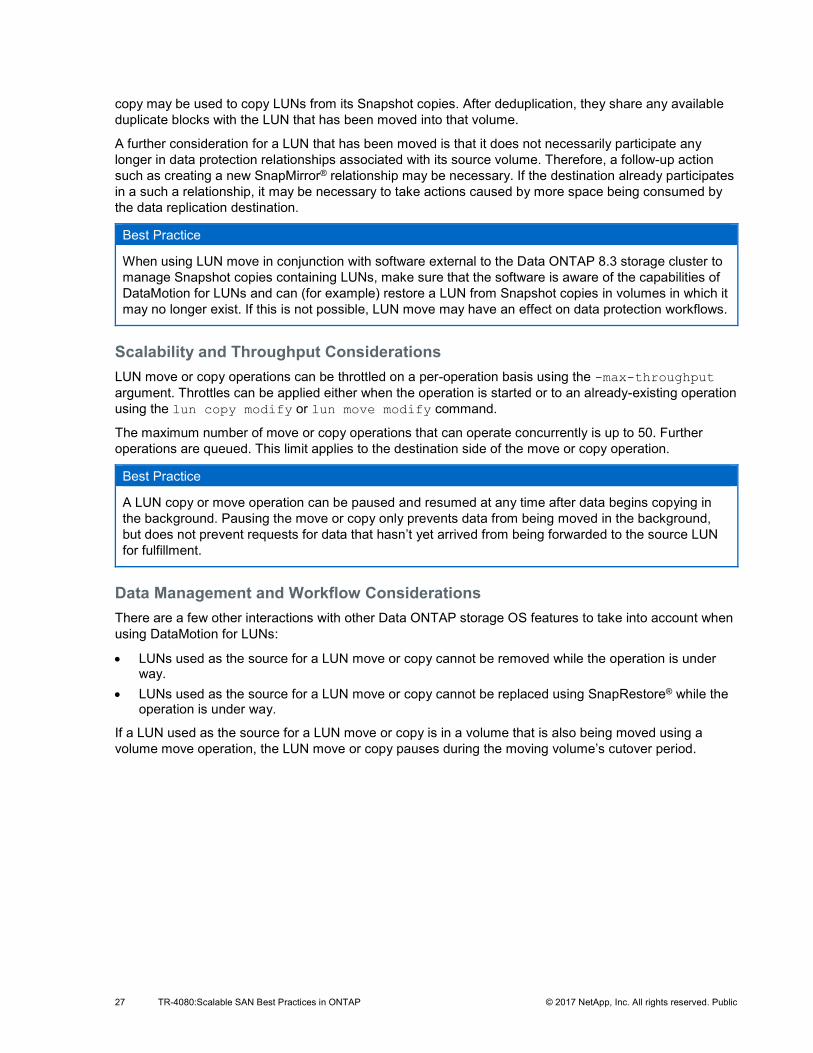
Figure 17) Management LIF details.
26 TR-4080:Scalable SAN Best Practices in ONTAP © 2017 NetApp, Inc. All rights reserved. Public
5.12 DataMotion for LUNs Starting in Data ONTAP 8.3, LUNs can be moved and copied between volumes, aggregates, storage controllers, and HA pairs on a per-LUN rather than a per-volume basis, using the lun move and lun copy commands, or using an API call.
LUNs moved or copied using this method become available almost instantly. After the destination LUN is created and its metadata and attributes arrive, the LUN is “promoted” so that it can receive I/O requests from hosts. Meanwhile, data from the source is copied in the background across the cluster interconnect. Incoming read requests for data that has not yet arrived at the destination trigger the destination to reach back to the source before fulfilling the read requests. Incoming write requests are written directly into the destination.
LUN Move and LUN Copy Comparison There are some differences between using DataMotion for LUNs to move a LUN and using it to copy a LUN:
LUNs may be copied between volumes in the same SVM or to volumes in other SVMs (when performed by a cluster administrator). LUN moves are only possible from volume to volume within the same SVM, because it can’t be assumed that the destination SVM has the same configuration. It has an entirely separate FC WWNN or iSCSI target name. Because the destination of a LUN copy does not have one or more LUN mappings to go with it, this is not a problem for inter-SVM copies.
The source of a LUN move must be in the active file system; the source of a LUN copy can be inside a Snapshot copy. Snapshot copies are immutable and cannot have data moved out of them.
By default, a LUN copy is promoted early, whereas a LUN move is promoted late:
• Early promotion means that a LUN can receive I/O, but Snapshot copies can’t be taken. • Late promotion means that a LUN can receive I/O and that Snapshot copies can be taken.
Storage Efficiency Considerations LUNs that have been moved or copied using DataMotion for LUNs do not arrive compressed or deduplicated at their destination.
Best Practice
If a destination volume previously has not contained deduplicated or compressed data, turning on deduplication or compression adds the arriving LUN’s blocks to the list of blocks to be processed during the next storage efficiency run, and they do not need to be discovered through a block scan.
Data can only be shared using deduplication or cloning within a volume; any data in a copied LUN is a duplicate of data in its source volume, and any data belonging to a LUN that is locked in a Snapshot copy on the source volume remains on disk until that Snapshot copy expires or is deleted, even if the LUN has been moved.
Volumes with inline compression turned on do not compress LUNs arriving through a DataMotion for LUNs operation.
Data Protection Considerations These considerations apply primarily to LUNs that have been moved and not copied, because a copy implies that the source data still exists in its source volume.
LUNs that have been moved do not bring with them any associated Snapshot copies that might still exist in the source volume. If the LUN data in the source volume’s Snapshot copies must also be moved, LUN
27 TR-4080:Scalable SAN Best Practices in ONTAP © 2017 NetApp, Inc. All rights reserved. Public
copy may be used to copy LUNs from its Snapshot copies. After deduplication, they share any available duplicate blocks with the LUN that has been moved into that volume.
A further consideration for a LUN that has been moved is that it does not necessarily participate any longer in data protection relationships associated with its source volume. Therefore, a follow-up action such as creating a new SnapMirror® relationship may be necessary. If the destination already participates in a such a relationship, it may be necessary to take actions caused by more space being consumed by the data replication destination.
Best Practice
When using LUN move in conjunction with software external to the Data ONTAP 8.3 storage cluster to manage Snapshot copies containing LUNs, make sure that the software is aware of the capabilities of DataMotion for LUNs and can (for example) restore a LUN from Snapshot copies in volumes in which it may no longer exist. If this is not possible, LUN move may have an effect on data protection workflows.
Scalability and Throughput Considerations LUN move or copy operations can be throttled on a per-operation basis using the -max-throughput argument. Throttles can be applied either when the operation is started or to an already-existing operation using the lun copy modify or lun move modify command.
The maximum number of move or copy operations that can operate concurrently is up to 50. Further operations are queued. This limit applies to the destination side of the move or copy operation.
Best Practice
A LUN copy or move operation can be paused and resumed at any time after data begins copying in the background. Pausing the move or copy only prevents data from being moved in the background, but does not prevent requests for data that hasn’t yet arrived from being forwarded to the source LUN for fulfillment.
Data Management and Workflow Considerations There are a few other interactions with other Data ONTAP storage OS features to take into account when using DataMotion for LUNs:
• LUNs used as the source for a LUN move or copy cannot be removed while the operation is under way.
• LUNs used as the source for a LUN move or copy cannot be replaced using SnapRestore® while the operation is under way.
If a LUN used as the source for a LUN move or copy is in a volume that is also being moved using a volume move operation, the LUN move or copy pauses during the moving volume’s cutover period.
28 TR-4080:Scalable SAN Best Practices in ONTAP © 2017 NetApp, Inc. All rights reserved. Public
Best Practice
Some existing workflows can take advantage of DataMotion for LUNs to shorten the number of required steps:
• Previously, to duplicate a volume containing LUNs, the entire volume needed to be cloned. Now any empty or already-occupied volume may be filled with LUN copies from another volume’s Snapshot copies, even if that volume is in a separate SVM. Effectively, the subvolume LUN cloning capability previously available within a volume can now be extended to other volumes.
• Previously, to change the existing layout and ratio of LUNs and volumes, it was necessary to clone volumes and then remove unneeded LUNs or to use a host-side copy using volume management to fill a new LUN with an old LUN’s data. Now, if storage efficiency can be better served by consolidating LUNs in fewer volumes, or if a single LUN in a volume containing others needs to relocate to satisfy performance or storage tiering needs, LUNs can be moved non-disruptively between volumes on the fly.
DataMotion and Selective LUN Mapping: Discovering and Discarding Paths When altering the LUN mapping on the storage cluster to create new paths or remove existing ones, the hosts attached to that LUN must perform a SCSI bus rescan. Therefore, when moving LUNs between HA pairs, the procedure should be as follows:
1. Change the LUN mapping to add the new reporting nodes using the lun mapping add-reporting-nodes command.
2. Perform a SCSI bus rescan on the hosts accessing the LUN, discovering the new paths. 3. Move the LUN non-disruptively; ALUA signals a path status change to the host, and the host begins
moving I/O down the new direct paths. 4. Change the LUN mapping to remove the old reporting nodes using the lun mapping remove-
reporting-nodes command. 5. Perform a SCSI bus rescan on the hosts accessing the LUN, discarding the old paths.
More than one LUN can have new paths discovered or old ones removed during a rescan.
For step-by-step instructions of how to perform a host SCSI bus rescan for all supporting operating systems, see the KB article on the NetApp Support site describing the procedure.
Caution
Do NOT remove reporting nodes until the LUN move is complete and any host remediation steps, for example, SCSI bus rescans, are completed. If reporting nodes are removed prior to adding new reporting nodes, completing the LUN move, and all host remediation steps are completed, you could lose access to the LUN that was moved.
5.13 Path Management Best Practices You should use Data ONTAP features to limit the number of available paths at the storage management level.
29 TR-4080:Scalable SAN Best Practices in ONTAP © 2017 NetApp, Inc. All rights reserved. Public
Best Practices • For storage controllers that have a single target LIF on each connected Fibre Channel fabric or
Ethernet network, the default number of paths presented by a LUN mapping is two direct paths from the storage controller that contains the volume and LUN being accessed and two indirect paths from its HA partner, for a total of four paths.
• Selective LUN mapping by default limits a LUN’s paths to the storage controller that owns it and its HA partner, but extra nodes may be part of a mapping on either a temporary or permanent basis.
• In clusters that have more than one target LIF per connected Fibre Channel fabric or Ethernet network, you can use the extra paths to provide more bandwidth or queue depth on a per-LUN basis, or portsets can be used to channel traffic on a per-igroup basis to specific LIFs.
• For LUNs that require more paths than a default LUN mapping provides, eight paths are almost always sufficient and is a path count supported by all host SAN implementations. For LUNs that require even more paths, the SAN Configuration Guide lists the tested maximum number of paths for each supported host OS.
• LUN mobility events such as vol move or lun move that involve moving a LUN from one HA pair in the cluster to another should include a step to confirm that the LUN is being presented using the destination storage controllers before the mobility event is initiated. The lun mapping add-reporting-nodes command can be used to add the new paths. After the move is complete, use the lun mapping remove-reporting-nodes command to remove the original, no longer direct path.
• Changing the paths presented for a LUN also means that a host SCSI bus rescan should be performed in order to discover new paths and discard stale ones. See section 5.12.6, DataMotion and Selective LUN Mapping: Discovering and Discarding Paths for best practices from a host perspective on path changes and for the procedure to be used when a LUN mapping must change to accommodate its moving to an HA pair that currently does not present paths.
• Because a change on the host accessing the LUN is necessary for a LUN mapping change, consider expanding the list of nodes in LUN mapping situations where administrative steps taken on the host are undesirable or when LUN mobility between HA pairs is frequent.
6 Scalable SAN Key Value Propositions and Features This section highlights some of NetApp’s principal design goals. These goals included providing a unified architecture at scale that enables non-disruptive operations for data mobility, performance optimization, capacity planning, and even system-level hardware replacement. Although this is not an exhaustive list of key features now available, it does show how scalable SAN features and the ONTAP storage OS are set apart from the rest of the storage market.
6.1 SVM as Unified Target and Unit of Management Storage controllers running Data ONTAP operating in 7-Mode, when a member of an HA configuration, already present a single WWNN to an attached Fibre Channel fabric. The storage cluster extends this single WWNN on an SVM basis to every member of a cluster, so that every node presents the same target and permits multiple targets to coexist on the same physical hardware.
The same concept also applies to storage management. Because all data is served from volumes associated with an SVM and from an iSCSI or FC target configured as part of an SVM, a cluster is administered on a per-SVM basis, rather than the time-consuming process of administering storage a single node at a time.

30 TR-4080:Scalable SAN Best Practices in ONTAP © 2017 NetApp, Inc. All rights reserved. Public
This focus on management at the SVM level means that it is possible to implement a secure multitenancy model of storage management.
6.2 Scalability at the Node and Cluster Levels The ONTAP storage OS offers scale at both the node level and cluster level and has increased the scalability at both since SAN protocols were introduced in Data ONTAP 8.1. For the latest full details about SAN configuration limits, see the SAN Configuration Guide. For a summary, see Table 3.
Table 3) Scalability in ONTAP.
6.3 Cluster-Wide Consistency Groups Snapshot consistency groups were introduced in ONTAP 8.2. Consistency groups are a way for Snapshot copies on multiple storage controllers to be taken simultaneously, allowing a host with LUNs served from multiple volumes within an SVM to synchronize Snapshot copy creation, which allows for consistent Snapshot copies across multiple LUNs even when those LUNs reside on multiple cluster nodes.
Rather than directing a Snapshot copy to be taken on multiple storage controllers at once, a host can take a copy across multiple cluster nodes and volumes simultaneously with a single command. Consistency groups work on a per-SVM basis, so any volumes owned by an SVM that is receiving the command are candidates for a Snapshot copy.
6.4 Intracluster LUN and LIF Mobility Previous versions of the ONTAP storage OS allowed volumes to be moved non-disruptively from any node to any other node in the cluster. Beginning with ONTAP 8.3, it’s also possible to copy and move LUNs between volumes and storage controllers on a per-LUN rather than a per-volume basis. LUN copy can be used to shorten cloning operations by making LUNs instantly available.
During normal operations, there is no need for LIFs or volumes to move from one cluster node to another, but in some circumstances non-disruptive migration of either volumes or LIFs from one node to another might be desirable.
Migrating LUNs and volumes from one node to another requires only that the destination node be able to provide a direct path for the host (see section 5.5, Path Selection).
Migrating a LIF from one node and port to another can be made less administratively burdensome by modifying rather than deleting and recreating it; its IP address or WWPN remains the same, so no fabric zoning or host changes are needed. SAN LIFs can be modified only when the LIF (but not the port) in question is offline. SAN LIFs can be set administratively offline by using the network interface modify –status-admin down command.
Version of clustered ONTAP 8.1 8.2 8.3 9 9.1
Nodes per cluster 4 8 8 8 12
LUNs per node 2,048 8,192 12,288 12,288 8,192
LUNs per cluster 6,144 49,152 98,304 98,304 98,304
iSCSI sessions/node 128 2,048 8,192 8,192 8,192
FC I_T_Ns/node 256 2,048 8,192 8,192 8,192
31 TR-4080:Scalable SAN Best Practices in ONTAP © 2017 NetApp, Inc. All rights reserved. Public
Best Practice
Do not exceed the cluster size limit when making changes to cluster membership. For information about the cluster size limit when using block protocols, see the ONTAP 9 SAN Configuration Guide.
6.5 Foreign LUN Import (FLI) Beginning in Data ONTAP 8.3, you can import LUNs from third-party arrays and first-party E-Series and EF-Series storage controllers using Fibre Channel.
This functionality is included in the Data ONTAP 8.3 software and does not require a license to use or any additional equipment; it only requires having some of a storage controller’s Fibre Channel or UTA2 ports set to initiator mode during the import process. If using UTA2 ports, those ports would need to be set to their FCP personalities, because Fibre Channel is the only transport FLI supports.
A storage controller performing a foreign LUN import (FLI) examines a LUN presented from an FC target to create a LUN of identical size and geometry inside an existing volume on its own storage and then creates a block-by-block copy of all the source LUN’s data, with offsets if necessary to maintain proper block alignment. Because LUNs created with the Data ONTAP storage OS are protocol agnostic, LUNs imported using FC may be presented to hosts using iSCSI the same way any native LUN could be.
This import procedure can be performed in online (as of Data ONTAP 8.3.1) or offline mode. An online FLI import means that the LUN is offline for only if it takes to create an import relationship between the source and destination LUN and for the host to mount the storage at its new location. I/O to that LUN can then continue as usual, with the Data ONTAP storage OS multiplexing incoming data to both source and destination until the import is complete and the relationship is broken. During an offline FLI import, both source and destination LUNs are inaccessible to hosts until the import has completed and the import relationship has been broken.
For an overall FLI migration strategy, see TR-4380.
Supported third-party arrays can be found by querying the FLI Interoperability Matrix Tool (IMT).
Beginning in Data ONTAP 8.3.1, imports can be performed using a NetApp storage controller running 7-Mode as a source. This is useful as a data transition strategy in cases where a LUN must have its alignment corrected during transition, or if it resides on an aggregate that must remain 32-bit. See TR-4380 for details about this version of the FLI procedure and TR-4052 for details about transition strategies.
7 Host Integration
7.1 NetApp Host Utilities Kit Installation of the Host Utilities Kit sets timeout and other operating system–specific values to their recommended defaults and includes utilities for examining LUNs provided by NetApp storage, whether clustered or operating in 7-Mode. See the NetApp Interoperability Matrix Tool for complete details for a given NetApp tested and supported configuration.
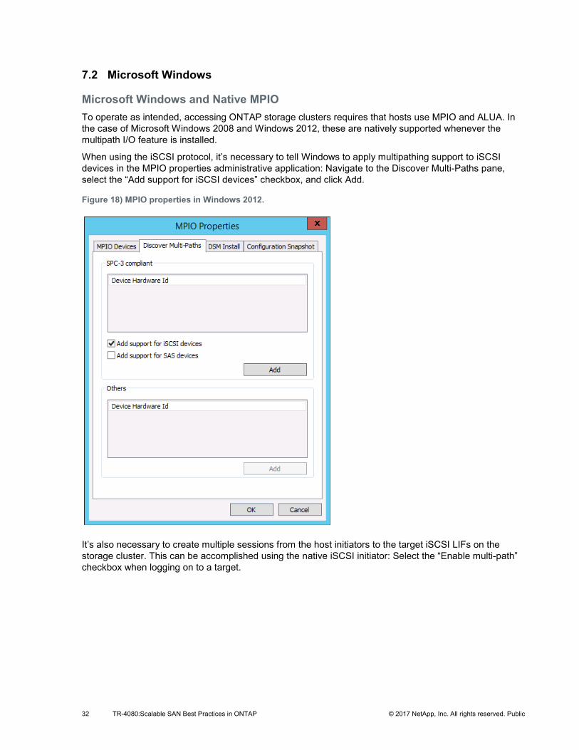
32 TR-4080:Scalable SAN Best Practices in ONTAP © 2017 NetApp, Inc. All rights reserved. Public
7.2 Microsoft Windows
Microsoft Windows and Native MPIO To operate as intended, accessing ONTAP storage clusters requires that hosts use MPIO and ALUA. In the case of Microsoft Windows 2008 and Windows 2012, these are natively supported whenever the multipath I/O feature is installed.
When using the iSCSI protocol, it’s necessary to tell Windows to apply multipathing support to iSCSI devices in the MPIO properties administrative application: Navigate to the Discover Multi-Paths pane, select the “Add support for iSCSI devices” checkbox, and click Add.
Figure 18) MPIO properties in Windows 2012.
It’s also necessary to create multiple sessions from the host initiators to the target iSCSI LIFs on the storage cluster. This can be accomplished using the native iSCSI initiator: Select the “Enable multi-path” checkbox when logging on to a target.
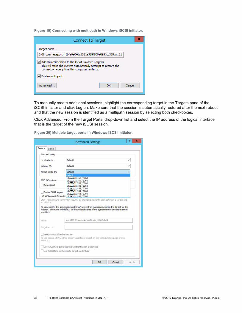
33 TR-4080:Scalable SAN Best Practices in ONTAP © 2017 NetApp, Inc. All rights reserved. Public
Figure 19) Connecting with multipath in Windows iSCSI initiator.
To manually create additional sessions, highlight the corresponding target in the Targets pane of the iSCSI initiator and click Log on. Make sure that the session is automatically restored after the next reboot and that the new session is identified as a multipath session by selecting both checkboxes.
Click Advanced. From the Target Portal drop-down list and select the IP address of the logical interface that is the target of the new iSCSI session.
Figure 20) Multiple target ports in Windows iSCSI initiator.
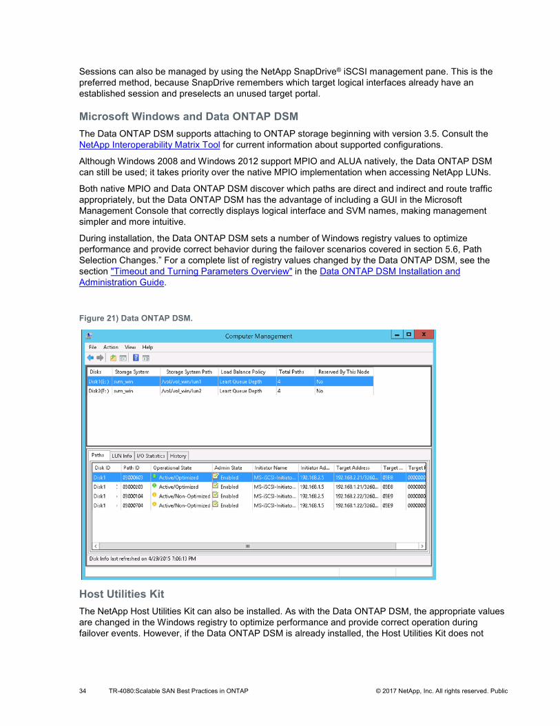
34 TR-4080:Scalable SAN Best Practices in ONTAP © 2017 NetApp, Inc. All rights reserved. Public
Sessions can also be managed by using the NetApp SnapDrive® iSCSI management pane. This is the preferred method, because SnapDrive remembers which target logical interfaces already have an established session and preselects an unused target portal.
Microsoft Windows and Data ONTAP DSM The Data ONTAP DSM supports attaching to ONTAP storage beginning with version 3.5. Consult the NetApp Interoperability Matrix Tool for current information about supported configurations.
Although Windows 2008 and Windows 2012 support MPIO and ALUA natively, the Data ONTAP DSM can still be used; it takes priority over the native MPIO implementation when accessing NetApp LUNs.
Both native MPIO and Data ONTAP DSM discover which paths are direct and indirect and route traffic appropriately, but the Data ONTAP DSM has the advantage of including a GUI in the Microsoft Management Console that correctly displays logical interface and SVM names, making management simpler and more intuitive.
During installation, the Data ONTAP DSM sets a number of Windows registry values to optimize performance and provide correct behavior during the failover scenarios covered in section 5.6, Path Selection Changes.” For a complete list of registry values changed by the Data ONTAP DSM, see the section "Timeout and Turning Parameters Overview" in the Data ONTAP DSM Installation and Administration Guide.
Figure 21) Data ONTAP DSM.
Host Utilities Kit The NetApp Host Utilities Kit can also be installed. As with the Data ONTAP DSM, the appropriate values are changed in the Windows registry to optimize performance and provide correct operation during failover events. However, if the Data ONTAP DSM is already installed, the Host Utilities Kit does not
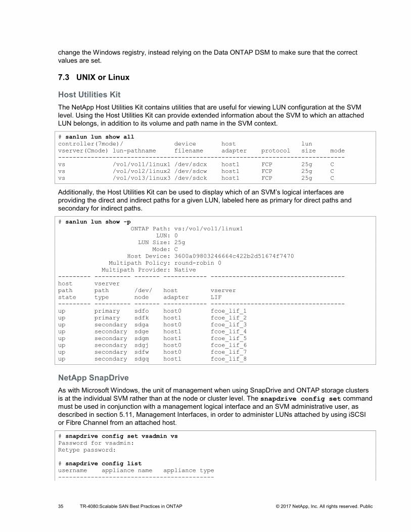
35 TR-4080:Scalable SAN Best Practices in ONTAP © 2017 NetApp, Inc. All rights reserved. Public
change the Windows registry, instead relying on the Data ONTAP DSM to make sure that the correct values are set.
7.3 UNIX or Linux
Host Utilities Kit The NetApp Host Utilities Kit contains utilities that are useful for viewing LUN configuration at the SVM level. Using the Host Utilities Kit can provide extended information about the SVM to which an attached LUN belongs, in addition to its volume and path name in the SVM context.
# sanlun lun show all controller(7mode)/ device host lun vserver(Cmode) lun-pathname filename adapter protocol size mode ------------------------------------------------------------------------------- vs /vol/vol1/linux1 /dev/sdcx host1 FCP 25g C vs /vol/vol2/linux2 /dev/sdcw host1 FCP 25g C vs /vol/vol3/linux3 /dev/sdck host1 FCP 25g C
Additionally, the Host Utilities Kit can be used to display which of an SVM’s logical interfaces are providing the direct and indirect paths for a given LUN, labeled here as primary for direct paths and secondary for indirect paths.
# sanlun lun show -p ONTAP Path: vs:/vol/vol1/linux1 LUN: 0 LUN Size: 25g Mode: C Host Device: 3600a09803246664c422b2d51674f7470 Multipath Policy: round-robin 0 Multipath Provider: Native --------- ---------- ------- ------------ ------------------------------------- host vserver path path /dev/ host vserver state type node adapter LIF --------- ---------- ------- ------------ ------------------------------------- up primary sdfo host0 fcoe_lif_1 up primary sdfk host1 fcoe_lif_2 up secondary sdga host0 fcoe_lif_3 up secondary sdge host1 fcoe_lif_4 up secondary sdgm host1 fcoe_lif_5 up secondary sdgj host0 fcoe_lif_6 up secondary sdfw host0 fcoe_lif_7 up secondary sdgq host1 fcoe_lif_8
NetApp SnapDrive As with Microsoft Windows, the unit of management when using SnapDrive and ONTAP storage clusters is at the individual SVM rather than at the node or cluster level. The snapdrive config set command must be used in conjunction with a management logical interface and an SVM administrative user, as described in section 5.11, Management Interfaces, in order to administer LUNs attached by using iSCSI or Fibre Channel from an attached host.
# snapdrive config set vsadmin vs Password for vsadmin: Retype password: # snapdrive config list username appliance name appliance type -------------------------------------------
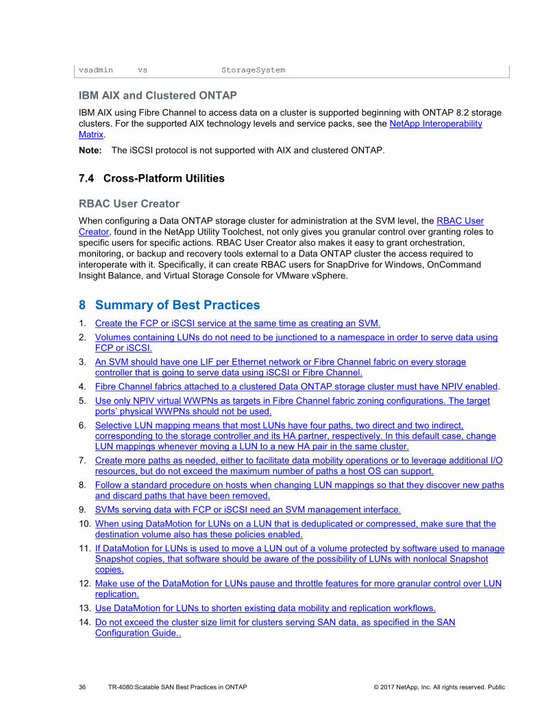
36 TR-4080:Scalable SAN Best Practices in ONTAP © 2017 NetApp, Inc. All rights reserved. Public
vsadmin vs StorageSystem
IBM AIX and Clustered ONTAP IBM AIX using Fibre Channel to access data on a cluster is supported beginning with ONTAP 8.2 storage clusters. For the supported AIX technology levels and service packs, see the NetApp Interoperability Matrix.
Note: The iSCSI protocol is not supported with AIX and clustered ONTAP.
7.4 Cross-Platform Utilities
RBAC User Creator When configuring a Data ONTAP storage cluster for administration at the SVM level, the RBAC User Creator, found in the NetApp Utility Toolchest, not only gives you granular control over granting roles to specific users for specific actions. RBAC User Creator also makes it easy to grant orchestration, monitoring, or backup and recovery tools external to a Data ONTAP cluster the access required to interoperate with it. Specifically, it can create RBAC users for SnapDrive for Windows, OnCommand Insight Balance, and Virtual Storage Console for VMware vSphere.
8 Summary of Best Practices 1. Create the FCP or iSCSI service at the same time as creating an SVM. 2. Volumes containing LUNs do not need to be junctioned to a namespace in order to serve data using
FCP or iSCSI. 3. An SVM should have one LIF per Ethernet network or Fibre Channel fabric on every storage
controller that is going to serve data using iSCSI or Fibre Channel. 4. Fibre Channel fabrics attached to a clustered Data ONTAP storage cluster must have NPIV enabled. 5. Use only NPIV virtual WWPNs as targets in Fibre Channel fabric zoning configurations. The target
ports’ physical WWPNs should not be used. 6. Selective LUN mapping means that most LUNs have four paths, two direct and two indirect,
corresponding to the storage controller and its HA partner, respectively. In this default case, change LUN mappings whenever moving a LUN to a new HA pair in the same cluster.
7. Create more paths as needed, either to facilitate data mobility operations or to leverage additional I/O resources, but do not exceed the maximum number of paths a host OS can support.
8. Follow a standard procedure on hosts when changing LUN mappings so that they discover new paths and discard paths that have been removed.
9. SVMs serving data with FCP or iSCSI need an SVM management interface. 10. When using DataMotion for LUNs on a LUN that is deduplicated or compressed, make sure that the
destination volume also has these policies enabled. 11. If DataMotion for LUNs is used to move a LUN out of a volume protected by software used to manage
Snapshot copies, that software should be aware of the possibility of LUNs with nonlocal Snapshot copies.
12. Make use of the DataMotion for LUNs pause and throttle features for more granular control over LUN replication.
13. Use DataMotion for LUNs to shorten existing data mobility and replication workflows. 14. Do not exceed the cluster size limit for clusters serving SAN data, as specified in the SAN
Configuration Guide..
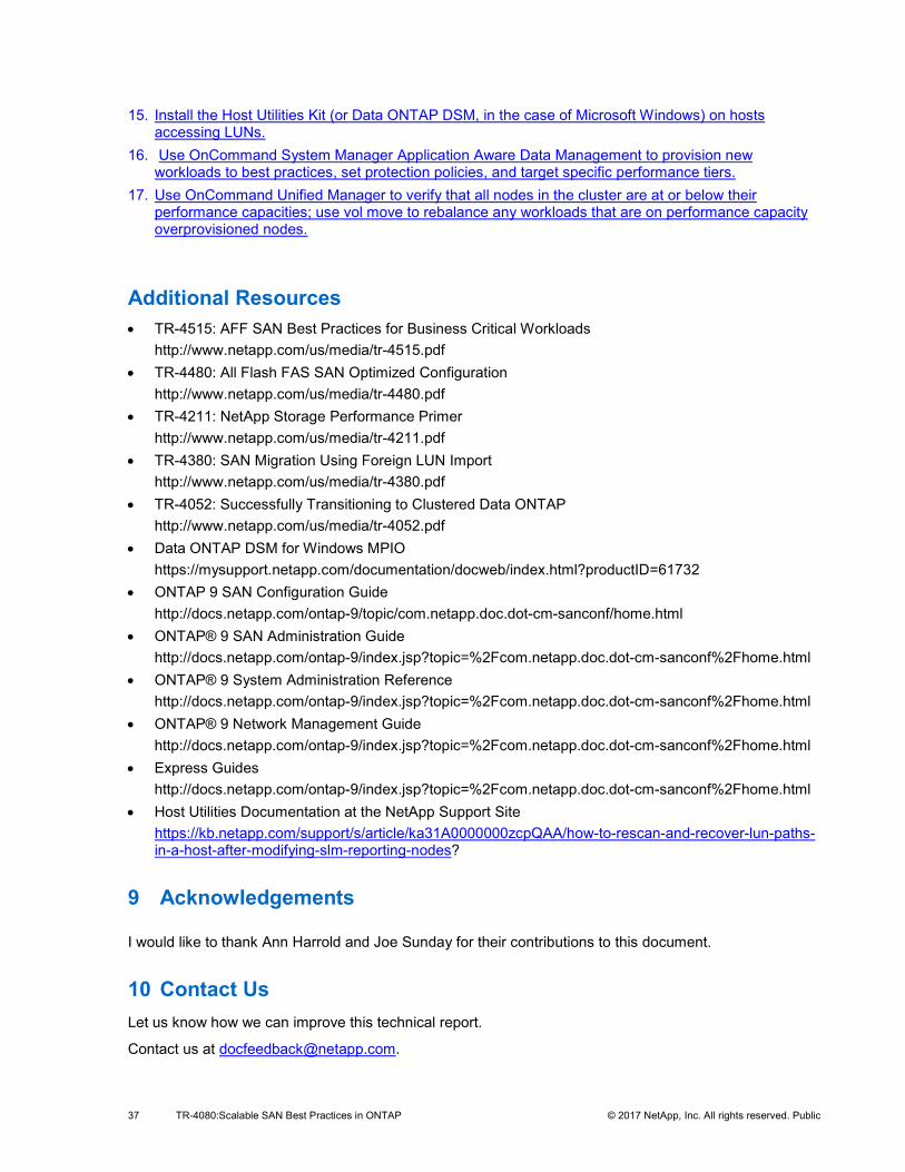
37 TR-4080:Scalable SAN Best Practices in ONTAP © 2017 NetApp, Inc. All rights reserved. Public
15. Install the Host Utilities Kit (or Data ONTAP DSM, in the case of Microsoft Windows) on hosts accessing LUNs.
16. Use OnCommand System Manager Application Aware Data Management to provision new workloads to best practices, set protection policies, and target specific performance tiers.
17. Use OnCommand Unified Manager to verify that all nodes in the cluster are at or below their performance capacities; use vol move to rebalance any workloads that are on performance capacity overprovisioned nodes.
Additional Resources • TR-4515: AFF SAN Best Practices for Business Critical Workloads
http://www.netapp.com/us/media/tr-4515.pdf • TR-4480: All Flash FAS SAN Optimized Configuration
http://www.netapp.com/us/media/tr-4480.pdf • TR-4211: NetApp Storage Performance Primer
http://www.netapp.com/us/media/tr-4211.pdf • TR-4380: SAN Migration Using Foreign LUN Import
http://www.netapp.com/us/media/tr-4380.pdf • TR-4052: Successfully Transitioning to Clustered Data ONTAP
http://www.netapp.com/us/media/tr-4052.pdf • Data ONTAP DSM for Windows MPIO
https://mysupport.netapp.com/documentation/docweb/index.html?productID=61732 • ONTAP 9 SAN Configuration Guide
http://docs.netapp.com/ontap-9/topic/com.netapp.doc.dot-cm-sanconf/home.html • ONTAP® 9 SAN Administration Guide
http://docs.netapp.com/ontap-9/index.jsp?topic=%2Fcom.netapp.doc.dot-cm-sanconf%2Fhome.html • ONTAP® 9 System Administration Reference
http://docs.netapp.com/ontap-9/index.jsp?topic=%2Fcom.netapp.doc.dot-cm-sanconf%2Fhome.html • ONTAP® 9 Network Management Guide
http://docs.netapp.com/ontap-9/index.jsp?topic=%2Fcom.netapp.doc.dot-cm-sanconf%2Fhome.html • Express Guides
http://docs.netapp.com/ontap-9/index.jsp?topic=%2Fcom.netapp.doc.dot-cm-sanconf%2Fhome.html • Host Utilities Documentation at the NetApp Support Site
https://kb.netapp.com/support/s/article/ka31A0000000zcpQAA/how-to-rescan-and-recover-lun-paths-in-a-host-after-modifying-slm-reporting-nodes?
9 Acknowledgements
I would like to thank Ann Harrold and Joe Sunday for their contributions to this document.
10 Contact Us Let us know how we can improve this technical report.
Contact us at [email protected].

38 TR-4080:Scalable SAN Best Practices in ONTAP © 2017 NetApp, Inc. All rights reserved. Public
Include TECHNICAL REPORT 4080 in the subject line.
39 TR-4080:Scalable SAN Best Practices in ONTAP © 2017 NetApp, Inc. All rights reserved. Public
Refer to the Interoperability Matrix Tool (IMT) on the NetApp Support site to validate that the exact product and feature versions described in this document are supported for your specific environment. The NetApp IMT defines the product components and versions that can be used to construct configurations that are supported by NetApp. Specific results depend on each customer’s installation in accordance with published specifications.
Copyright Information
Copyright © 1994–2017 NetApp, Inc. All rights reserved. Printed in the U.S. No part of this document covered by copyright may be reproduced in any form or by any means—graphic, electronic, or mechanical, including photocopying, recording, taping, or storage in an electronic retrieval system—without prior written permission of the copyright owner.
Software derived from copyrighted NetApp material is subject to the following license and disclaimer:
THIS SOFTWARE IS PROVIDED BY NETAPP “AS IS” AND WITHOUT ANY EXPRESS OR IMPLIED WARRANTIES, INCLUDING, BUT NOT LIMITED TO, THE IMPLIED WARRANTIES OF MERCHANTABILITY AND FITNESS FOR A PARTICULAR PURPOSE, WHICH ARE HEREBY DISCLAIMED. IN NO EVENT SHALL NETAPP BE LIABLE FOR ANY DIRECT, INDIRECT, INCIDENTAL, SPECIAL, EXEMPLARY, OR CONSEQUENTIAL DAMAGES (INCLUDING, BUT NOT LIMITED TO, PROCUREMENT OF SUBSTITUTE GOODS OR SERVICES; LOSS OF USE, DATA, OR PROFITS; OR BUSINESS INTERRUPTION) HOWEVER CAUSED AND ON ANY THEORY OF LIABILITY, WHETHER IN CONTRACT, STRICT LIABILITY, OR TORT (INCLUDING NEGLIGENCE OR OTHERWISE) ARISING IN ANY WAY OUT OF THE USE OF THIS SOFTWARE, EVEN IF ADVISED OF THE POSSIBILITY OF SUCH DAMAGE.
NetApp reserves the right to change any products described herein at any time, and without notice. NetApp assumes no responsibility or liability arising from the use of products described herein, except as expressly agreed to in writing by NetApp. The use or purchase of this product does not convey a license under any patent rights, trademark rights, or any other intellectual property rights of NetApp.
The product described in this manual may be protected by one or more U.S. patents, foreign patents, or pending applications.
RESTRICTED RIGHTS LEGEND: Use, duplication, or disclosure by the government is subject to restrictions as set forth in subparagraph (c)(1)(ii) of the Rights in Technical Data and Computer Software clause at DFARS 252.277-7103 (October 1988) and FAR 52-227-19 (June 1987).
Trademark Information
NETAPP, the NETAPP logo, and the marks listed at http://www.netapp.com/TM are trademarks of NetApp, Inc. Other company and product names may be trademarks of their respective owners.