technical report fluid flow analysis of the ssme high
TRANSCRIPT
LMSC-HEC TR F268780
TECHNICAL REPORT
ii i1 I 1 q I [I
FLUID FLOW ANALYSIS OF THE SSME
HIGH PRESSURE FUEL AND OXIDIZER TURBINECOOLANT SYSTEMS
i
i 6
JULY 1989
Contract NAS8-36284
i .
=
t.,.t
= =
Prepared for
NATIONAL AERONAUTICS AND SPACE ADMINISTRATION
GEORGE C. MARSHALL SPACE FLIGHT CENTER
MARSHALL SPACE FLIGHT CENTER. AL 35812
(NA'_A-C_,-!63730) FLUIO FLOW ANALYSIS OF THE
SSME HIgH PRESSI_!RF FUeL AND oxIr_IZER TUR_INF
CfIQLANT SYSTEMS (LMS£) 67 p CSCL 7'IN
Nq0-i4277
unclas
G_3/_0 0231737
/wss/P.s & Space _ny,/no.Huntsville Engineering Center
41100 Bradford Blvd., Hunlsville, AL 35807
_ r
mine
LIL_C-HEC TR F268780
i
TECHNICAL REPORT
FLUID FLOW ANALYSIS OF THE SSME HIGH PRESSURE FUEL
AND OXIDIZER TURBINE COOLANT SYSTEMS
July 1989
Contract NAS8-36284
L •
m
u
Prepared for
NATIONAL AERONAUTICS AND SPACE ADMINISTRATION
GEORGE C. MARSHALL SPACE FLIGHT CENTER, AL 35812
by
G.A. Teal
LOCKHEED MISSILES & SPACE COMPANY, INC.
HUNTSVILLE ENGINEERING CENTER
HUNTSVILLE, AL 35807

LMSC-HEC TR F268780
=
FOREWORD
This document presents the results of work performed
for NASA-Marshall Space Flight Center by the Computational
Mechanics Section of the Lockheed Missiles & Space Company,
Inc., Huntsville Engineering Center. This work was performed
for NASA-MSFC under Contract NAS8-36284, with Dr. Helen
McConnaughey serving as technical monitor.
0931R
ii
w
LOCKHEED-HUNTSVILLE ENGINEERING CENTER

LMSC-HEC TR F268780
m
m
Section
CONTENTS
FOREWORD
INTRODUCTION AND SUMMARY
I.I Objectives
1.2 Summary
GENERAL THEORY OF FLUID FLOW RELATIONS
2.1 Flow Equations
2.2 Bearing Model
2.3 Labyrinth Seal Model
2.4 Therm_odynamic and Transport Properties
HIGH PRESSURE FUEL TURBINE COOLANT ANALYSIS
3.1 Turbine Coolant System
3.2 Model Improvement3.3 Results
3.4 Program Input Guide
HIGH PRESSURE OXIDIZER TURBINE COOLANT ANALYSIS
4.1 Turbine Coolant System
4.2 Model Improvement4.3 Results
4.4 ProEram Input Guide
REFERENCES
P a_e_
ii
1-1
1"-1
2-1
2-1
2-5
2-5
2-5
-..I
3-1
3-1
3-3
3-3
4-1
4-1
4-1
4-20
4-20
5-1
Tab ie
2-1
3-I
3-2
3-3
4-1
4-2
4-3
LIST OF TABLES
Pressure Loss Factors (K)
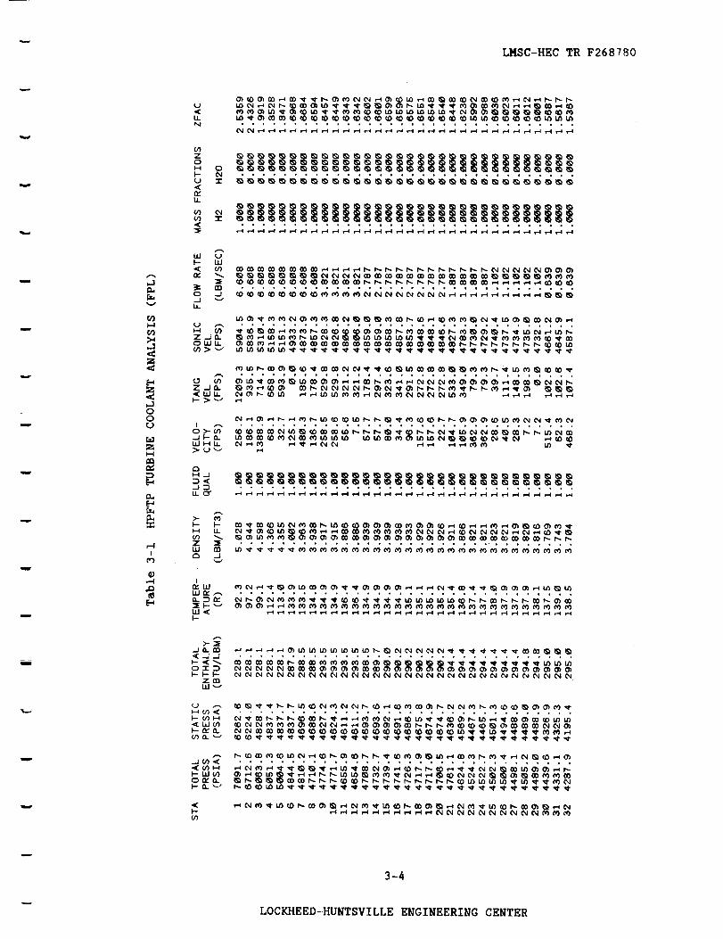
HPFTP Turbine Coolant Analysis (FPL)
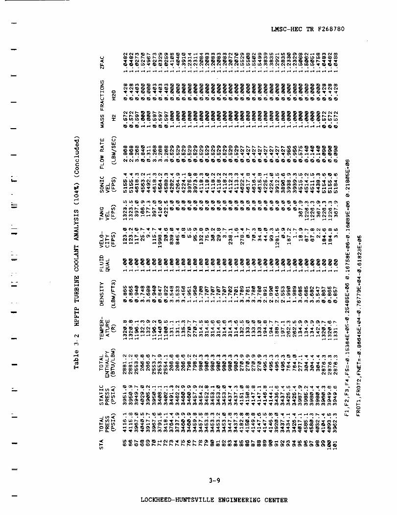
HPFTP Turbine Coolant Analysis (I04%)
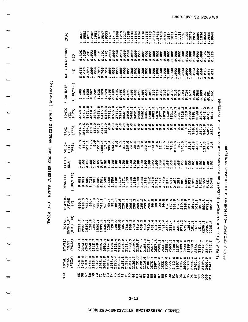
HPFTP Turbine Coolant Analysis (MPL)
HPOTP Turbine Coolant Analysis (FPL)
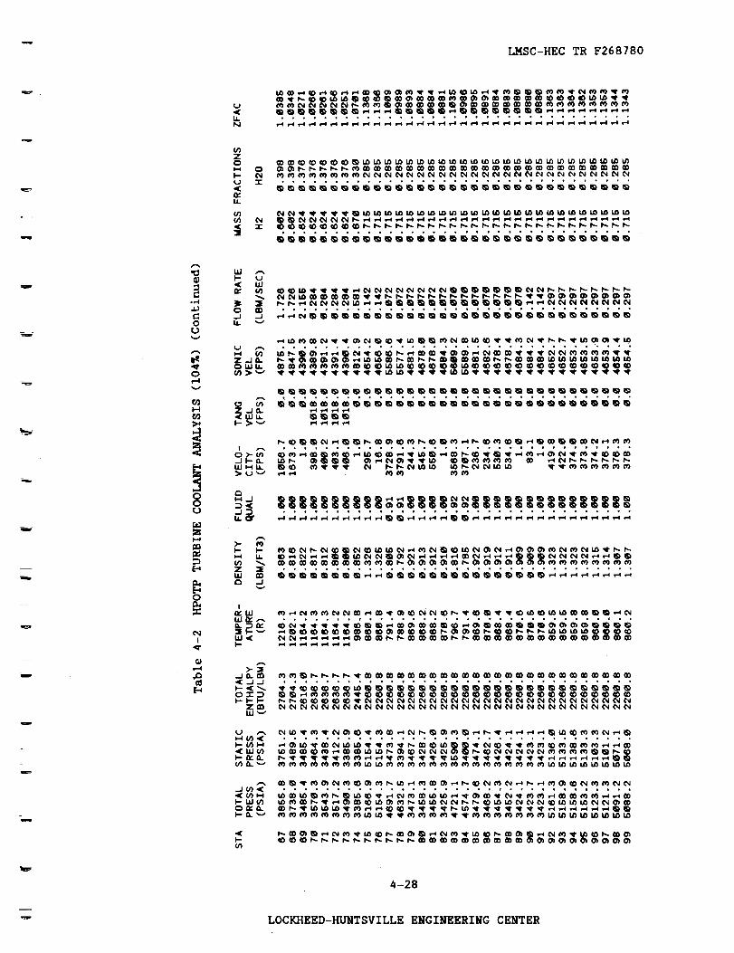
HPOTP Turbine Coolant Analysis (104%)
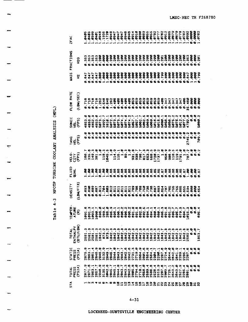
HPOTP Turbine Coolant Analysis (MPL)
PaK_
2-2
34
3-7
3-10
4-21
4-26
4-31
iii
LOCKHEED-HUNTSVILLE ENGINEERING CENTER

LMSC-HEC TR F268780
LIST OF ILLUSTRATIONS
m
FiKure
3-1
4-1
4-2a
4-2b
4-2c
4-2d
4-2e
4-2f
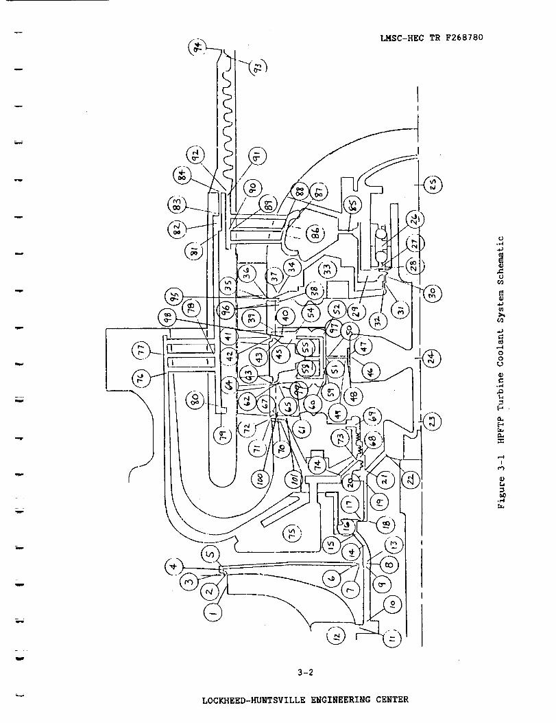
HPFTP Turbine Coolant System Schematic
HPOTP Turbine Coolant System Schematic Diagram
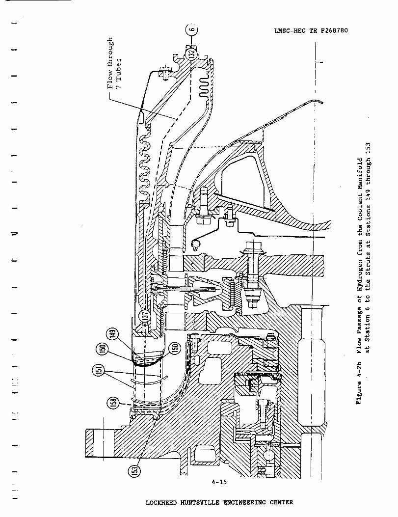
Flow Passage of Hydrogen from the Coolant Manifold at
Station 6 to the Turbine Seal Region at Station 131
Flow Passage of Hydrogen from the Coolant Manifold at
Station 6 to the Struts at Stations 149 through 153
Flow Passage of Mixed Coolant from the Mixing Chamber
at Station 8 to the First Stage Rotor at Stations 22
and 28
Flow Passage of Mixed Coolant from the Mixing Chamber
at Station 8 to the Turbine Stator Region at Stations 63
and 66
Flow Passage of Mixed Coolant from the Mixing Chamber at
Station 8 to the Turbine Housing at Stations 42 through
50 and Exit Strut Region at Stations 75 through 90
Flow Passage of Mixed Coolant from the Mixing Chamber at
Station 8 to the Second Stage Rotor at Station 109
3-2
4-2
4 --14
4-15
4-16
4-17
4-18
4--19
iv
LOCKHEED-HUNTSVILLE ENGINEERING CENTER

LMSC-HEC TR F268780
I. INTRODUCTION AND SUMMARY
I.I OBJECTIVES
l
w
The objective of this study is to provide improved analysis capability
for the Space Shuttle Main Engine (SSME) high pressure fuel and oxidizer
turbine coolant systems. Each of the systems was analyzed to determine fluid
flow rates and thermodynamic and transport properties at all key points in the
systems.
I. 2 SUMMARY
Existing computer codes developed by Lockheed for NASAMSFC were used as
a baseline for these analyses. These codes were modified to provide improved
analysis capability. The major areas of improvement are listed below.
u
• A review Of the drawings was performed, and pertinent geometry changes
were included in the models.
• Improvements were made in the calculation of thermodynamic and
transport properties for a mixture of hydrogen and steam.
A one-dimensional turbine model for each system is included as a
subroutine to each code. This provides a closed loop analysis with a
minimum of required boundary conditions as input.
• An improved labyrinth seal model is included in the high pressure fuel
turbine coolant model.
The modifications and the analysis results are presented in detail in the
following sections.
i-I
m_
\ LOCKHEED-HUNTSVILLE ENGINEERING CENTER

LMSC-HECTR F268780
2. GENERAL THEORY OF FLUID FLOW RELATIONS
The fluid flow model solves the steady state continuity, momentum, and
energy equations to obtain thermodynamic and transport properties at various
stations in the coolant systems. The models compute changes in fluid flow
properties between stations using coolant system geometrical data, pressure
loss factors, heat transfer rates, and bearing and labyrinth seal models
discussed below.
i
2.1 FLOW EQUATIONS
The mass continuity, momentum, and energy conservation equations are cast
in one'dimensional, incompressible form to describe the fluid flow from station
to station. The continuity equation states that the fluid flow rate ls con
served from station to station. The momentum equation is cast in the fot_
P = P - _p + _PT2 T1 loss cen
o
where
and
PT2 is the total pressure at the downstream station
P is the total pressure at the upstream stationT1
6Ploss is the change in pressure due to friction or turbulence
AP is the change in pressure due to centrifugal effects.cen
The term APloss depends on the type of flow passage involved and is
evaluated using the relationship
APloss = K (pV_ /2 gc )
2-1
LOCKHEED-HUNTSVILLE ENGINEERING CENTER

LMSC-HEC TR F268780
where
and
p is the fluid density
VF is the fluid flow velocity (excluding centrifugal components)
g is the gravitational constantc
K is a pressure loss factor that depends on the type of flow.
The values of K for several types of flow may be obtained from Ref. 1 and are2
presented in Table 2-1. The dynamic pressure term PVF/2 gc is evaluated at
the station with the smaller flow area.
Table 2-I PRESSURE LOSS FACTORS (K)
Type of Passage I Value of K (Ref. I) Remarks!
Smooth Pipe
(Darcy Weisbach)
Mitered Bend
Sudden Expansion
Sudden Contraction
Entrance from
Large Volume
Exit to Large
Volume
K = fL/D
K = fL /De
2
K = [I - (DI/D2)2]
K = 0.50
K=0.23
K = 0.04
K= 1.0
f = 0.1841R 0"2
L = length
D = hydraulic diameter
R = Reynolds number
L = equivalent lengthe
(See page A-27 of Ref. I)
DI = smaller hydraulic .diameter
D 2 = larger hydraulic diameter
See page A-26 of Ref. 1
Sharp-edged entrance
Rounded entrance
Well-rounded entrance
V F = 0.0 (small flow velocity)
2-2
-- LOCKHEED-HUNTSVILLE ENGINEERING CENTER
LMSC-HEC TR F268780
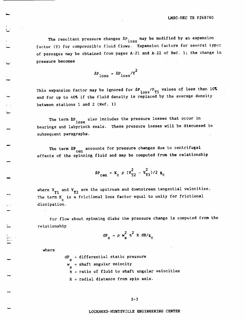
The resultant pressure changes _Ploss may be modified by an expansion
factor (Y) for compressible fluid flows. Expansion factors for several types
of passages may be obtained from pages A-21 and A-22 of Ref. I; the change in
pressure becomes
2
_Ploss = _Ploss/Y
This expansion factor may be ignored for _Ploss/PTl values of less than 10%
and for up to 40% if the fluid density is replaced by the average density
between stations 1 and 2 (Ref. i)
The term _Ploss also includes the pressure losses that occur in
bearings and labyrinth seals. These pressure losses will be discussed in
subsequent paragraphs.
The term AP accounts for pressure changes due to centrifugalten
effects of the spinning fluid and may be computed from the relationship
2 2
_Pcen = Kc p (VT2 - VTI)/2 gc
where VTI and VT2 are the upstream and downstream tangential velocities.
The term K is a frictional loss factor equal to unity for frictionalc
dissipation.
For flow about spinning disks the pressure change is computed from the
relationship
2 2
= p w _ R dR/g cdPs s
where
dP = differential static pressures
w = shaft angular velocitys
= ratio of fluid to shaft angular velocities
R = radial distance from spin axis.
2-3
LOCKHEED-HUNTSVILLE ENGINEERING CENTER

LMSC-HEC TR F268780
w
Relationships for n may be obtained from Ref, 2 for inward and outward
flows through smooth and bladed disk/housing configurations, The effect on
total pressure hP must be determined from dP and dynamic pressure.cen s
These various contributions to pressure changes also affect the energy of
the fluid through the energy equation
QI-2
HT2 = HTI + m + _Hcen
w
m
w
where
HT = total enthalpy per pound of fluid
QI-2 = heat transferred to the fluid
AH = change in total enthalpy due to centrifugal effects.cen
Changes in pressure due to centrifugal effects result in a change in total
enthalpy equal to
gH = AP Ipcen cen
For spinning disks the heat generation term AH becomes (Ref. 2):cen
P (RI- R2) C
AHcen = \ 60/ _ 4 gc J m
where C is a coefficient depending on disk/housing configuration,m
and J = 778.2 Ibf-ft/Btu,
w i
The above equations represent solutions to the general flow equations
which will adequately describe the flow in the coolant systems.
2-4
LOCKHEED-HUNTSVILLE ENGINEERING CENTER

LMSC-HECTR F268780
2.2 BEARING MODEL
w
The bearing model computes the pressure drop in the fluid flowing through
ball bearings. The pressure loss term AP B is computed by solving the
quadratic equation
_(APB)2 .2- m (AP B) - _ _2 = 0
where
2 2
= 288 p gc A C
2 (2_N/60) 2
B = p (RK) 288 gc
N = shaft rpm
The coefficients A, C, R, and K are bearing constants supplied by NASA-MSFC.
2.3 LABYRINTH SEAL MODEL
The labyrinth seal model now used by the high pressure fuel turbine
coolant model is an empirical leakage prediction program for straight-through
labyrinth seals developed for NASA-MSFC by Texas A&M University (Ref. 3).
This program is included as a subroutine in the fuel turbine coolant program.
2.4 THERMODYNAMIC AND TRANSPORT PROPERTIES
The high pressure fuel and oxidizer turbine coolant systems are complex
flow systems comprising several flow paths in which the fluid is pure hydrogen
and other flow paths containing a mixture of H 2 and H20. Thermodynamic and
transport properties for hydrogen are computed from the GASP computer code
(Ref. 4).
To evaluate real thermodynamic properties for H2/H20 gas mixtures the
WASP computer code (Ref. 5) is used to calculate H20 properties. The gas
2-5
LOCKHEED-HUNTSVILLE ENGINEERING CENTER

LMSC-HECTR F268780
components are assumed to occupy the entire volume at the mixture temperature
and pressure, and the thermodynamic properties are mass fraction weighted to
obtain mixture properties. The compressibility factor is assumed to obey the
law of additive volumes and is computed accordingly.
To obtain thermodynamic properties for a mixture containing H20 in the
liquid phase, the following procedure is employed:
• PM and HM are the known thermodynamic properties (except at
turbine inlet and discharge stations where PM and TM are known)
• Assume TM and compute PV
e Check if PH20 > PV (two-phase if true)
• Compute a gas phase mole fraction required to give PH20G = PV
• Compute KL and XG
• HTM = XH HH + XL H L + XG HG
• Iterate on TM until HTM = HM.
This procedure is extended to include the solid region when PM and HM are
known. However, in the solid region, the thermodynamic state cannot be
defined by PM and TM alone.
In general, the properties routine evaluates thermodynamic properties of
H20 for four separate regions:
I. TM > Tcrit
Composition is all gas, properties evaluated at PM and TM
2. TM < Tcrit' PV > PM
Composition is all gas, properties evaluated at PM and TM
.
PV < PM' PV > PH20Composition is In vapor state.
Enthalpy is evaluated by computing liquid enthalpy at PM and TM
and adding the heat of vaporization. Transport properties are
evaluated for saturated vapor only.
w
2-6
LOCKHEED-HUNTSVILLE ENGINEERING CENTER

LMSC-HEC TR F268780
L,,,_
L_
iii
H
PV < PM' PV < PH 0
Composltion is t_o-pha_o
- Liquid/vapor
- Liquid
Vapor phase is negligible
- Solid/liquid
Vapor phase is negligible
- Solid
Vapor and liquid phases negligible
where
TM = mixture temperature
PM = mixture pressure
Tcrit = critical temperature of H20
PV = vapor pressure of H20 at TM
PH20 = H20 partial pressure based on total mixturemole fraction
PH2OG = H20 partial pressure based on gas phasemole fraction
XL
xG
HH
H L
HG
%.
= the mass fraction of liquid H20 in the
total mixture
= the mass fraction of H20 vapor in thetotal mixture
= H 2 enthalpy at PM and TM
= H20 liquid enthalpy at PM and TM
= H20 vapor enthalpy at PM and TM
= mixture enthalpy
= computed mixture enthalpy.
In the two-phase region, the mixture density computed by the program is
the homogeneous two-phase density. The compressibility factor is computed for
the gas phase only.
Transport properties are evaluated for a mlxture of gases using the method
of Wilke for computing viscosity and the method of vanderslice for computing
thermal conductivity (see Reference 6). Mixture transport properties are
evaluated for the gas phase only.
2-7
LOCKHEED-HUNTSVILLE ENGINEERING CENTER

LMSC-HEC TR F268780
3. HIGH PRESSURE FUEL TURBINE COOLANT ANALYSIS
.!i!vs_
z_
3.1 TURBINE COOLANT SYSTEM
The existing high pressure fuel turbopump (HPFTP) turbine coolant system
flow model developed by Lockheed for NASA-MSFC was used as a baseline for this
analysis. This baseline model (shown in Figure 3-1) is documented in Ref-
erence 7. The turbine coolant system was modeled to evaluate the flow proper-
ties at each of the numbered stations shown in Figure 3-1 and to compute the
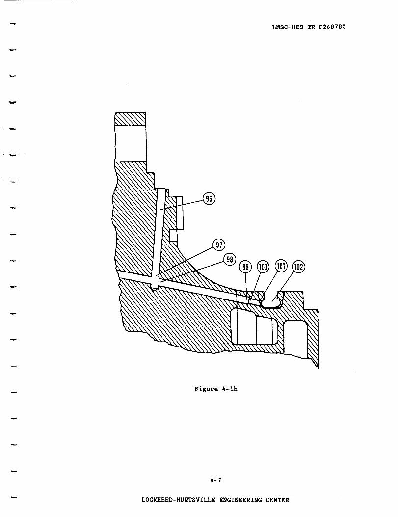
flow rates along each of the flow paths in the system. Two additional flow
paths have been added to compute flows through the turbine blade fir trees.
These are the first stage blade fir trees (stations 95 through 98) and the
second stage blade fir trees (stations 99 through I01). The model comprises
I01 stations and 25 flow paths.
3.2 MODEL IMPROVEMENT
A review of current drawings was performed and pertinent geometry changes
were included in the model. Operating clearances for the turbine blade
platform seals, labyrinth seal, and the lift-off seal were supplied by NASA-
MSFC.
A one-dimensional turbine model is included as a subroutine in the code.
This provides a closed loop analysis with a minimum of required boundary con-
ditions as input. Estimated platform seal leakage rates are input to the
turbine model, and the turbine model is executed to provide pressures as
boundary conditions for the coolant flow model (stations 35, 41, 64, and 72).
The coolant model is then executed and new leakage flows are computed. An
input option is provided for terminating the execution at this point or con-
tinuing with another pass through each model if greater accuracy is desired.
= _
3-1
LOCKHEED-HUNTSVILLE ENGINEERING CENTER
LMSC-HECTR F268780
= _w
w
w
r_
iI
i
ii-_}/
L.
fir ..
I1| 0"
)
3-2
,,.4
,,-Ioo_D
0)C.,4
_-_
n.
,-4I
0%
o$.,4
LOCKHEED-HUNTSVILLE ENGINEERING CENTER

LMSC-HECTR F268780
An improved labyrinth seal leakage prediction program developed for
NASA-MSFC by Texas A&M University (Ref. 3) is included as a subroutine in the
turbine coolant program.
An improved properties subroutine for computing thermodynamic and trans-
port properties for a mixture of H 2 and H20 has been added to the program.
See Section 2.4 for a detailed description of this calculation procedure.
3.3 RESULTS
The fuel turbine coolant system was analyzed at full power level (FPL),
104% and minimum power level (MPL), using Rocketdyne engine balance data
obtained from Reference 8. The results of these analyses are presented in
Tables 3-1 through 3-3. These results are for a balance piston high pressure
orifice gap of 0.004 inch.
3.4 PROGRAM INPUT GUIDE
This section describes the input data file required for execution of the
HPFTP turbine coolant program.
Column Parameter Description
Line number I, Format (8EI0.4)
I-I0 GAP Balance piston high pressure orifice
gap, in.
Line number 2, Format (8EI0.4)
I-I0 RDEFO
11-20 RDEFI
21-30 XDEF
Housing radial deflection at high
pressure orifice, in.
Impeller radial deflection at high
pressure orifice, in.
Impeller axial deflection at high
pressure orifice, positive toward
turbine, in.
3-3
LOCKHEED-HUNTSVILLE ENGINEERING CENTER
LMSC-HEC TR F268780
w
w
w
w
w
u
w
I-4Cn
>4
00
1-1
0.,
r-4I
,-4
Zo
I-
<
tl_
_9U_<
•,,o,ooo,oo,,,,,s,_ooo_ooooo°,o,
wW
,_ O9tw .-..
_j .._
I-4 o')Z ._ a,.oWI.Log>,J
P%
<WU-_- > ,._
&,._"LLI _-I IS.
_.-4 _J
U.._'
e'_ --I
t_W
_ I-- "---'
I-
__ o_ o_
o'1" D
7mtO'-"
_CW09
o0£0.}- O._-,
o9
..... o • ° o o , ° , ° ° • • o o ° • o • • • • • ° ° , ° °
o,o,•o,ooooooooooo_o,,o,o_oooo,o
,o ....... o.,o,•_°oo,o,,o,oooooo•
...... • ooooo°o,,°°•°°°••°ooo,°°,
•oooo•ooo_o_,••,o•oo•ooo_•o_o,o,o
ooo•oooo .... oo•_ooo•_o•,,,,,_,o•
...... • o•ooooo.o ....... °o,•o•°••
.......... oooo .... °•o,oo••oo•ooo
3-4
LOCKHEED-HUNTSVILLE ENGINEERING CENTER

m
LMSC-HEC TR F268780
"O
.,4
.o
O
_Dv
,-%
_a
v
>4
00U
E-I
I
,....4
LLN
O9
Z0
U -r<
U_
O9 04
O9 -r
wI-- W
O9
3Err,
O J
_j _.sLL
H O9ZJ0-C3 LLI U.
r_¢._ O9ZJ0-,_C W LL
O _- (/)Jl--a-b_ I-I LL
C_I-G_Jm_
JDLLc_r
H LL.
O9 "._Z
_tLL I
LLI r_" ,.--,
"51--,...,UJ_I--
j__rn
I-- < "_.C3 :r :D
I-- I-- I--
LLI_
_C LLI O9
O9 r,.. v
..,J £t) <°_ O9 I,--II'-W_C3 rw __I--0 _,
i--
O9
........... ,o,o,o0_°,oo.0,,,0ooo
oo,o,,0 .... °o,o,,o,o°,.,,0o,.,,.
.,oo°°°,ooo_,°,,,,_°,°o.o,,°°°°°
o°o,°°°°o°o°,°,,o,°,,o°,_,°°°°°°
°.,,°o°°°°,°°°°o°o,°,,°°°°,_ooo°
oo,°°°°°,°°°°°°°°°o°°o°oo.°°o°°°
........ °.°°°°°°o .... 0°.°° .... °°
,°,°o°,,°°o,°°°,,°o°°,°°o,.°°,,o
.......... °o .......... .° ........
..... o°o,°0°,,°°o,°°o°,.°°°°°,o°
°°°°°°°,,°,°°,o°°°°,°°°_o°°oo°°
3-5
"-- LOCKHEED-HUNTSVILLE ENGINEERING CENTER

LMSC-HEC TR F268780
T
mini
n
u
I
C)
OL)v
J
_L
v
k-4
C/)
E-_
OO_._
Z
m_
E-4r..
,-4I
-4
i,N
ZO
U
U-
c0
_- _J
CD
U-
z/a.Olll_
Z.J_-.(Whp--> --_
>uv
r_H._J
--J3Cl._-
I.- I--M _co "_Z '_
I_ 1.1.1
.,_ .J .J
" ZI_
<hl_
/ o') _K.(COil
oE_.I-_.v
o')
Q+
W
.... ,°°,,.,.°,°,..°°.°.°...o,°,°.,.o°
.... °° • °° °° ° o
_ _ _ _ _ _ _ _ _ _ +
...... °°°°°0°°,°°,,,°,,,°°,,°,°°,,,,°
!
• °''°'*,,°.°.,0..,°.,.,..,,,,,._. _ ®
!
o°'oo0o0°°o*,o_ooo_*°_°oo_o°.o°o..00. _ _W
''°°°°°'°°°'°°°°°°°°*°*''°°''°°°°"°'° _ II
...... °,,°,..°,.,°, .... ,,°,,,°.°,0°,° _
o
...... °°,°°°°°°.°°°°°,,°°°°°°°°°,°°,°
3-6
LOCKHEED-HUNTSVILLE ENGINEERING CENTER

u
LMSC-HEC TR F268780
B
i
m
=
m
O,-4
U)>_
OO
L,JZ_4
,,...4
,m
t.)
Zo
n
< O5
COo .2
u_
O5Z ..J_I.OUJU-O5 > ,.w
JO--( tU U__- > -._
0>-09J I,- o_W _-4U.
_-4_JD<JDu. cr
I-4 U.09 _.Z :2EW CO
J
I_W
>-"5-2 O- _0_ J ,,,.I
o-r_D
(_O.v
_[ O5 _.,,_I--WO5O0_0.
o5
o °oo°.... • ° 0 0 • 0 • • ° • • ..... • • • , • ° ° ° • • • °
......... 0 .... 0•••o••o•°•o•°0o•°
• • .......... •o•o••.000••••0 .... ,
............. • ...... 00•000•0••.•
•••0••0.•00•°•0_•o•.•••••0•00000
° ........................... • • • •
• 0•••00000.0•••0•0 ..............
o•• ....... oo•••o• ...............
............ o .... • • • ......... • • •
3-7
LOCKHEED-HUNTSVILLE ENGINEERING CENTER

LMSC-HECTR F268780
l
m
m
u
o,-4
OtD
Or-4v
t_
O9
oor.D
Br.1
I-4
[-4
r..
¢Ni
<iiU
(.,')Z0I.-4I.-
IJ.
W
n_
O-2U.
..... ,0°o.o_°• .... 0,.°00.o.•,•00
C_I
Wto
"5m.2
H tOZ .-J O-OWl,
oZ.2O._C L_JLLp- > ,-,
_J
D<.2DLLCr
2H LLtO "_ZUJ _0t',,
..................... _ ._ . ._ . .
..... • ooo• ...... •00°o°.0°0o0o0•o
o0.,,00,°°°.o,•oo0,,..o0.0.0,,,,__ _ _ _ __'_ __ _ _
o .... • ........ • ........ °
00•, ......... • ........ •.° ......
.,J ,", _o_J.J
o1,,,::3_ I,- l-
AmBi_1 ..,_s
............. • 0,,_°,0°0°°°,•0•0•
.2_ ,0° ..... °° ..... •0,, .......... °•.
,(I,,-tO
3-8
LOCKHEED-HUNTSVILLE ENGINEERING CENTER
LMSC-HEC TR F268780
m
w
mm
m
u
i
m
,-4
OL)v
,,-%
O,-4v
{aI.....4
>4
00r_
Z
[-I
A
.,--t
u.1[
N
_9ZoH O
u -r.(
i,
(n 04(n "I-
wF- hl
O -J
H (nZ-JD.OUJLL
C._ ('9Z --JO-<hlU_
O>-(n.J_O.W _-4LL
_-_.JD'(-JDu. or
H h09Z 3Eill ,n_3 .J
v
in- w
w.<
>,..,_
t.-- ,<: "%
zmILl,.-,
I-- _ k.4.<WV)t,-_
_J_,_
O_.D_i-- O. _-
)--
....... o ...................... ,°°°.o,
.......................... ,,o,o,o,o,,
o.o°..o..o°. .................. ,o..o.o
• • • • o , • • • o • o • • • o • o • , • • , o • • • • • • • • • • • • ,
,÷
_ _ r-._ m- t-._ _ _ _ _ _ _ _ _ _ _ _ _ _ _ _ _ _ _ _ _ _ _ r.._ _-_ _ _- +
_D
.......... , 0 , 0 , 0 0 0 , , , 0 , . . , 0 , , 0 o o 0 0 , 0 ,
_l (_J _-I (_1 ,_-_O) Ol _1 __- I_) {'f_ t,.- (_ {%1 _) i'_ b-- (_ _l" O) _ _0 _-I (0 _0 _0{0 I I_
uJ ('4OD _0
• . , ....... , . , , . 0 0 0 , 0 0 ° ° • ° . • , , 0 0 , 0 0 . ° , _
I
• • • • • • • • • • • • • , • • • • • • • • • • • , • • • • • • • • * • • I._ _
•q" b-ix)
....................... o , ..... , ...... _ +
_.9 (:oh9
I.... , o , , o o . o o o o . o , ...... o o o , o o , o o o o o o
I_) II IlJ
...... • • • ° • 0 • • • • • • • • • • • • • , • 0 0 0 • 0 • • • • • 0'_ /%"
C3
• , 0 • 0 , 0 0 0 • , 0 • 0 • • 0 • , 0 0 • • • 0 0 • • • • • , 0 , , , °
3-9
n
LOC_EED-_NTSVILLE ENGINEERING CENTER

4-
LMSC-HEC TR F268780
L
w
w
u
v
C_
OO_D
Z
D
It,
i
,-.4
L_
LLU
tOZO
t)<
tL
_OCO
............ • °°°, ...............
-r
wILlCO
__ vt_m
..........................
• ° .... ,°°.°,°°°°°,°°°°°, ........
r_
D_
2
Z •W O0
_WuJ Oc ,.-_
]_ _..v
..J 0.. _1,_ ...j jI,.-.- ,,_ _.
ZOOU./",-"
I,- CO _-I,_WCOI-- O_ O.
I-WCO
_r_ v
................ °°°°,, ........ ,,
,°.,°°°°°° .............. °.°,,°°o
.......... °°,° ..................
3-10
LOCKHEED-HUNTSVILLE ENGINEERING CENTER

u
LMSC-HEC TR F268780
m
m
=
G)
,-I.4J
OrJv
.I
v
{4I-4C/l:M
L_
r_
p.l
I
,-.4
c0
u.(iiN
(/)zoi.-db.-v
n,,LL
COO9,(
...0o00o,,0oo,°,,,oo.o,,0.,,°0°°
i'MZ
wI- tU•_ (/)
(:D -.I,_1 v
UH (/}ZJ&.0 UJ Lt.
Z/O._{WLLl-->v
O >- (/)J I- I_.W _-dLL>L) v
l..d..J
-JDU__f
>. _"I-- I-
(/) ,-_Zill _7,'% j
v
t_ll.l.l
We.-.-...0..D _-"_:l-vl.IJ_I--
_j O_ an.l:JJ
O:=:D
Z_OWV
I-I(/:I<I-- (_ H
_O_v
..J (,')_:
I--UJ 0')
_O_v
I--
G_G;GG_GG_;G;_G_GGG_GGGG_VVjGG_
...... __ ..................... _
.o°,o.°,o,oooo,,0,0.0.°o,.,,0,,.
.... °°°,, .... ,ooo,ooo,0 .... °.o._
• o°.°o.o0.0ooo.ooo..oo .... ooo..o
3-11
LOCKHEED-HUNTSVILLE ENGINEERING CENTER
-- LMSC-HEC TR F268780
w
3,-4
U
OL>v
v
U_H
00
Z
pl
1
u
u.N
(/)Z0
0l-- ('4U "1"
n_LL
CO tN(/) -r
w_- W
mo J_j __su.
_J P_
Z-JO.OWh
<._ cOZ--O-_WtL
._,1 t..- 0,...UJ H I.L
0H_I:),<
tL C_"
I1.
ZUJ nn0 .J
_UJ
W,<
.J o_ _I•< .J .JI-.(_
,,< (_ HI-W_
I-
..°......°..°..... .... °°°°..0°.°°°...
....°°°..°..°°.°..°°...°°.°...° ......
.°°...._.°..°.°°o°.°.°._°.°.....°.o°.
....°.,.°°,.,.,°°°°.°.°.° .... °°,,°...
W
°°°..°°,,.,°°°°°.,...°,°...°..,°..°.. _
3-12
-- LOCKHEED-HUNTSVILLE ENGINEERING CENTER

LMSC-HEC TR F268780
I
Column Parameter Description
Line numbers 3 through 103, Format (15,5X, 6EI0.4)
1-5 IP
11-20 A
21-30 D
31-40 XL
41-50 XR
51-60 XK
61-70 EFF
Flow type
Passage flow area, in2
Passage hydraulic diameter, in.
Passage effective length for frictional
losses, in.
Radial location, in.
Flow loss coefficient
Ratio of fluid to shaft rotational speed.
w
w
Line number I04, Format (8EI0.4)
I-I0 BAREA
11-20 BRAD
21-30 BC
31-40 BK
Bearing area, in 2
Bearing pitch radius, in.
Empirical constant
Empirical constant.
Line number I05, Format (215, 7FI0.5)
Data for interstage labyrinth seal
1-5 N
6-10 J
11-20 CL
21-30 PL
31-40 HL
41-50 WL
51-60 DSHF
61-70 DCASE
71-80 DCL
Final tooth number, enter 4
Parameter not used; enter 0
Radial clearance from drawings, in.
Tooth pitch, in.
Tooth height, in.
Tooth width, in.
Shaft diameter, in.
Case diameter, in. = DSHF+2(CL+HL)
Change in diametral clearance at
operating conditions, in.
3-13
LOCKHEED-HUNTSVILLE ENGINEERING CENTER

" LMSC-HEC TR F268780
Column Parameter Description
w
Line number 106, Format (215, 7F10.5)
Data for first two teeth of turbine seal
1-5 N Final tooth number, enter 6
6-80 Same parameters as above.
Line number 107, Format (215, 7FI0.5)
Data for next three teeth of turbine seal
1-5 N Final tooth number, enter 9
6-80 Same parameters as above.
= ..w
= =
Line number 108, Format (215, 7FI0.5)
Data for final three teeth of turbine seal
1-5 N Final tooth number, enter 12
6-80 Same parameters as above.
Line number 109, blank card image.
Line number ii0, Format (815)
1-5 IOPT = 1 Fixed blade coefficient and
iterates to determine flow rate
= 2 Fixed flow rate and iterates to
determine blade coefficient
6-10 IOPTXI = 1 Enter total pressures in pump
input data
= 2 Enter static pressures in pump
input data
11-15 ITURB = I Uses programmed turbine leakage
flows and makes one pass throughturbine and coolant flow models
= 2 Uses computed leakage flows from
first pass and makes an additional
pass through each model
16-20 KPUMP = I Reads input impeller inlet and
discharge conditions and bypasses
pump head rise model
= 2 Computes impeller inlet and
discharge conditions using pumphead rise model.
3-14
LOCKHEED-HUNTSVILLE ENGINEERING CENTER

LMSC-HECTR F268780
Column Parameter
Line number III, Format (8EI0.4)
I-I0 WPIO
11-20 PIOF
21-30 TIOF
31-40 POOF
41-50 TOOF
51-60 ETAP
61-70 RPM
71-80 XPL
Description
Pump inlet flow rate, Ibm/s
Pump inlet pressure, psla
Total pressure if IOPTXI = 1
Static pressure if IOPTXI = 2
Pump inlet temperature, °R
Pump discharge pressure, psia
Total pressure if IOPTXI = 1
Static pressure if IOPTXI = 2
Pump discharge temperature, °R
Pump efficiency
Pump speed, rpm
Power level ratio.
w
Line number 112, Format (8EI0.4)
I-i0 PKNOWN(1)
11-20 TKNOWN(1)
21-30 RKNOWN(1)
31-40 VTKNON(1)
Line number 113, Format (8EI0.4)
I-I0 PKNOWN(2)
11-20 TKNOWN(2)
21-30 PKNOWN(2)
31-40 VTKNON(2)
Impeller discharge total pressure, psia
Impeller discharge temperature, °R
Impeller discharge density, Ibm/ft 3
Impeller discharge fluid tangential
velocity, ft/s.
Impeller inlet total pressure, psia
Impeller inlet temperature, °R
Impeller inlet density, Ibm/ft 3
Impeller inlet fluid tangential
velocity, ft/s.
3-15
"- LOCKHEED-HUNTSVILLE ENGINEERING CENTER

LHSC-HEC TR F268780
. I
m
Column Parameter
Line number 114, Format (8EI0.4)
I-I0 WDPB
11-20 PPB
21-30 TPB
31-40 HPA
41-50 TFTD
51-60 PFTD
61-70 ETANZ
71-80 XKB
Line number 115, Format (8EI0.4)
i-i0 OF
Line number 116, Format (8EI0.4)
1-80 WDLEG
Line number 117, Format (8EI0.4)
1-80 WDLEG
Line number 118, Format (8EI0.4)
1-80 WDLEG
Description
Turbine inlet flow rate, ibm/s
Turbine inlet total pressure, psia
Turbine inlet total temperature, °R
Turbine horsepower, hp
Turbine discharge total temperature, °R
Turbine turnaround duct discharge total
pressure, psia
Nozzle efficiency, Kn2
Blade coefficient, Kb.
Preburner mixture ratio.
Legs 1 through 8 estimated flow rate at
FPL, Ibmls.
LeEs 9 through 16 estimated flow rate
at FPL, ibm/s.
LeEs 17 through 24 estimated flow rate
at FPL, Ibm/s.
Line number 119, Format (8EI0.4)
I-I0 WDLEG Leg 25 estimated flow rate at FPL,
ibm/s.
3-16
-- LOCKHEED-HUNTSVILLE ENGINEERING CENTER

LMSC-HE¢TR F268780
4. HIGH PRESSURE OXIDIZER TURBINE COOLANT ANALYSIS
4.1 TURBINE COOLANT SYSTEM
!
mm_
w
The existing high pressure oxidizer turbopump (HPOTP) turbine coolant
system flow model developed by Lockheed for NASA-MSFC was used as a baseline
for this analysis. This baseline model (shown in Figures 4-1 and 4-2) is
documented in Reference 9. The turbine coolant system was modeled to evaluate
the flow properties at each of the numbered stations and to compute the flow
rates along each of the flow paths in the system. Four additional stations
have been included in the model for computational purposes. These are at the
first stage blade exit (station 159), second stage nozzle exit (station 160),
second stage blade exit (station 161), and primary turbine seal inlet (station
162). The model comprises 162 stations and 27 flow paths.
4.2 MODEL IMPROVEMENT
A review of current drawings was performed, and pertinent geometry changes
were included in the model. Operating clearances for the interstage seal and
turbine seal were supplied by NASA-MSFC. The flow path supplying coolant
hydrogen to the turbine seal region at station 131 (see Figure 4-2a) has been
modified and now supplies mixed coolant from the mixing chamber. The cold
hydrogen supply has been blanked off, and mixed coolant is now introduced at
old station location 122 shown in Figure 4-1m. This flow path now consists of
stations 120 through 131.
A one-dimensional turbine model is included as a subroutine in the code.
This provides a closed loop analysis with a minimum of required boundary
conditions as input. Estimated leakage rates into the primary turbine flow
path are input to the turbine model, and the turbine model is executed to
provide pressures as boundary conditions for the coolant flow model (stations
29, 159, 160, and 161). The coolant model is then executed and new leakage
4-1
LOCKHEED-HUNTSVILLE ENGINEERING CENTER

u_
w
w
®
LMSC-HEC TR F268780
_-2
.,4
t)U)
.O
_O
.O
OOL)
0)C
0
I
D
.,-4
LOCI_{EED-HUNTSVILLE ENGINEERING CENTER

LMSC-HEC TR F268780
= =
= =
_ _ 0
0 _'_
C _ u _
O
ouC
0 C _
I |
4-3
I,,,I"
I-i
.I-I
t
LOCI(HEED-HUNTSVILLE ENGINEERING CENTER

LMSC-HECTR F268780
®
Figure 4-1b
Figure 4-ic
4-4
LOCKHEED-HUNTSVILLE ENGINEERING CENTER

.LMSC-HEC TR F268780
E
E
r
m
(84
Figure 4-1d
F '
--:::_
w_a
I II I
I I
_ Denotes nodes
at which pres-sures are bal-
anced and flows
summed.
Figure 4-1e
4-5
LOCKHEED-HUNTSVILLE ENGINEERING CENTER

LMSC-HEC TR F268780
mu_
...o
_ Idl I
--"4911
'_ALl
_ Denotes nodesat which pres-sures are bal-
anced and flows
summed.
Figure 4-1f
._'_i_'_2 ____ _
Figure 4-1g
4-6
LOCKHEED-HUNTSVILLE ENGINEERING CENTER
LMSC-HECTR F268780
\p.a.
Figure 4-1h
4-7
_- LOCKHEED-HUNTSVILLE ENGINEERING CENTER

w
LMSC-HEC TR F268780
w
w
= =
z :
W
Figure 4-Ii
F
_ Denotes nodes
at which pres-
sures are bal-
anced and flows
summed.
Figure 4-1j
4-8
LOCKHEED-HUNTSVILLE ENGINEERING CENTER

LMSC-HECTR F268780
®
Figure 4-1k
A
[lqlIILII
,
Figure 4-i_
4-9
LOCKHEED-HUNTSVILLE ENGINEERING CENTER

LMSC-HEC TR F268780
Section A-A
Figure 4-1m
Figure 4-1n
4-I0
LOCKHEED-HUNTSVILLE ENGINEERING CENTER

LMSC-HECTR F268780
m
f
k.,
! %
! J
f
_ Denotes nodesat which pres-
sures are bal-
anced and flows
summed.
m
Figure 4-1o
m
<D
m
m
Figure 4-1p
4-11
LOCKHEED-HUNTSVILLE ENGINEERING CENTER

LMSC-HEC TR F268780
Figure 4-1q
u
- i
u
Flow Splits
Figure 4-1r
4-12
LOCKHEED-HUNTSVILLE ENGINEERING CENTER

w
LMSC-HEC TR F268780
m
m
w
m
i
Figure 4-1s
4-13
LOCKHEED-HUNTSVILLE ENGINEERING CENTER

m
m
m
w
4-14
LMSC-HEC TR F268780
•"40O .,_
.,_
CC
,.-400.,4OU 0_
0_
O
Co_
C_
o
_-_ oo ,_
_ o_ .,.4
o
cNI
°_
LOCKHEED-HUNTSVILLE ENGINEERING CENTER
l
w
//
/
II
//
/
LMSC-HEC TR F268780
4-15
LOCKHEED-HUNTSVILLE ENGINEERING CENTER
u_,-4
,-4 _0o
o
C_
O_
,-4 _
o Co o
_.) .,4
,_.o
o _I.
.o
o _
_ oo ._
m C_ o_ .,.4
o
,o
t
t,

LMSC-HEC TR F268780
/
i-
i
u
m
= •
= =
=
\
v
4-16
LOCKHEED-HUNTSVILLE ENGINEERING CENTER
ooc_
e.m
• _ d.l
xm
N o
_0
,,...4o.l.J
N _
m e.,m o_ .,.4
_mo
_b
I

w
L o
i
m
5
//
r
"T
LMSC-HEC TR F268780
%-17
1I
_D
,,.,4
C.o
_ o.r,l
o oL_J
_o
C
O*,_O.O
.,.4 ,_
_/1 °,4
0
I
-- LOCKHEED-HUNTSVILLE ENGINEERING CENTER

i
w
m
w
L__
8
//
/
/
LMSC-HEC TR F268780
f///f_
4-18
\
TI
--'7--
I
I
i
LOCKHEED-HUNTSVILLE ENGINEERING CENTER
oo
C
c_4.)
X
O_n
X o°_
o
o_' O0
--_ 0
X
_ o C"_ o
o o-_
• .,.4 ._
_ .0 I:11
I
.,.4

LMSC-HEC TR F268780
w
/
[
1°0Co
_._.._ .o
.,-4_._
oO_' o
c _0
.-_ .oo _0O
O
X
o .o
o
u_ (30
Co
o
I
LOCKHEED-HUNTSVILLE ENGINEERING CENTER

w
m
. l
w
--4
LMSC-HEC TR F268780
flows are computed. An input option ls provided for tecmlnating the execution
at this point or continuing with another pass through each model if greater
accuracy is desired.
An improved properties subroutine for computing thermodynamic and trans-
port properties for a mixture of H2 and H20 has been added to the program.
Refer to Section 2.4 for a detailed description of this calculation procedure.
4.3 RESULTS
The oxidizer turbine coolant system was analyzed at FPL, I04%, and MPL
using Rocketdyne engine balance data obtained from Reference 8. The results
of these analyses are presented in Tables 4-1 through 4-3.
4.4 PROGRAM INPUT GUIDE
Th[s section describes the input data file required for execution of the
HPOTP turbine coolant program.
Column Parameter Description
Line numbers 1 through 158, Format (15, 5X, 6EI0.4))
1-5 IP
11-20 A
21-30 D
31-40 XL
41-50 XR
51-60 XK
61-70 EFF
Flow type
Passage flow area, in2
Passage hydraulic diameter, in.
Passage effective length for frictional
losses, in.
Radial location, in.
Flow loss coefficient
Ratio of fluid to shaft rotational
speed.
4-20
LOCKHEED-HUNTSVILLE ENGINEERING CENTER

• m
LMSC-HEC TR F268780
t]
U.N
09
H O
0_m,
O509 t_
_l__''_''_ __. .. _ _®_.. I_
__i °_" _ _" _" _I|.,0,..°,°°°,.,°,°,, ......... 0,_t,
__ii _ _ __ _ |i
=
m
o. _
w
w_
=
w
P%
v
00
0
,-iI
,.-t
ill
• ILlll_ 09
OJ
09Z ..J _-OWU.09 > ,-_
ZJ_-<LULL
>-09
>U'-"
D•
>- _
(_ '_.
?_ ..Iv
Ie_'UJUJ _: ,.-.,
._2_I--
,,.11_ IIXI
O-rD_- p- p-
_e
t--?,_I..-_•U.J__m._."_.09_m v
P_
• 09 t"__" U.J09O0_O._O..v
" "_='_l_!!! ___li'' !t®i_® tI_®® -.--_---®®®_®_®- -o,°00,,,°
GVGVG4_GGGGGG&G&_GG&_GGJGGGGG
...°.o.,,..o.°.°., .... .,°,.o°,.o
m
!!!!!!!!!!!!!!!!!!!!!!!!!!!!!!!!
®_ _''_ _Z_ __®_ _'_o,=,,,,,.,,,,.,,,,,,o .... ,,,o,.,
o°.,,°,°.... ..... ° ..... . ..... ..°
i-°_i--i--i-----l---i_l°-!i_°-_.. .°
......°.° .... .°.°°..,..o ........
..,...,,, ..... °°°,,.,.._.°°0°°,.
°,,,°,,.,, ....... 0.°.,,,,,..,,,,
4-21
LOCKhEED-HUNTSVILLE ENGINEERING CENTER

LMSC-HEC TR F268780
w
r -
°-4
0r..)
..]
,-3
E-t
oorD
BUZ
E-I0
r-iI
u
iIN
¢,.; "l-
ivI,L
W
,_ UJO_ 09
mo aB.J J
Z.J0.OWLL
Z.JB._UJU._->_-
O>-_JF-B.UJH[,
D_JD
> 2I- I-
g
I
I--
>-_.-I o. II_
Z_nLI.I _."
I-I (/) _"I.- (_ I.-I_I: LU (/)
J(/)_,((/) HI-- U.I v)o_nI-- (L v
p-(t)
• ° o , , o o _ • • • • • • ° • o ° o , • • , ° • ° • ° o o o • • ,
0°, ..... 0_°00,,°°,_0.**0000,°0°,,
° ..... °°°°,o=°°,,,°.°,,°°,°° ..... ,
oo°,,,,,,°_o,°°°°°°°,,0°°,o°,o°°_°
o,o°°°°°°_,°°°,o°°,_o°°°°°o,°°°°°,
4-22
LOCKHEED-HUNTSVILLE ENGINEERING CENTER

LMSC-HEC TR F268780
ti
w
I
f__
m
"o
°,_
-6-)
Ot.)
.I
{n
{4
OOL_
tU
H
0
I
,,,,.4
U
I.LN
ZOD-_ (D
U "r
U.
(/)G9.( :E
UJ
.( uJIZ (;1
O ,n
.J ..JLL "-.-"
U
Z ,.J IL•,_ W LLI,.- > _
>Uv
65
H--ID'(
H U.
¢'_ _1
_m.u
_v
w,(_m
>-=i
_{ ..J _J
z_
U _m-4 _ _tm.- _ _..._
_,-._ _.(_ _.. v
_.J_
............ ,.,...,,,,,,.°,...oo.
...,,,°l°O°.°l,,°°°°,,.,,,,°,°,..°
.,°_,_,,,,°°°°_,°,°,°°,,_,,_°°,,_
°°°_,,,,,°,.,°°°,lO,O°,,°,°°,,,,i
...... ,°,,.°°,°°°°°,.,,,°,°,o°°.°
4-23
" LOCKHEED-HUNTSVILLE ENGINEERING CENTER

F
LMSC-HEC TR F268780
w
e
w
°,4
o_Jv
3
v
U_
OOL)
H
0
I
[-I
u
N
H 0
_j "1-,(
ii
,( "r"
I-- U'( W
O ,nJ
u s-_H ¢0Z ,..J 0,.OWU.
_.Ja.W"
O>-¢0J i- Q..
> ,,.)v
,..,.
)- 2I-- I--
Z •UJ (1_
I
UJ _ ,,..,
%2_vLU__m
>'•..J_ m'¢t.--i..J
O'_:D
zm_v
_ _,)_.._
_m _,"_.
_ bU (#)O_-__I-._. v
_t
°,,,.°°,,,.,,°°°°°°°o°,,,°,,_°.°o
®__®_ ®® ®®8®®®°°° ..... °°,,,, .... °,°,,,,,,,,,°,,
,°.°,,,,,,,,,,°,o,,, ..... ,,,°°°°°
_;_,_,_,_lilllli!i_,_,_,-° .>-• , ..... ° • ° ° ° ° , , ° , ° • ° ° , ° ° ° , ° , , , , ° ,
.°..., ..... °o,,°,, ...... ,, .......
.............. °°.,°°°°,,°°°,.,,,,
I||lilii|ll|llll||l|tl|ll|ll|l|l ®,°,,°°°°°°°,°°°.°.o.,, ...........
!iii!1! --°" i _-'"!
itiiiii__'""'"|1_"_.._ i_i iii"::_ _
...°,°,,,,,,,°,°,°,°°,°,°°°,°,°.°.
.o.°°°°°°°°°,,°°,,,°,°,°.°°_°,°°°,
4-24
LOCKHEED-HUNTSVILLE ENGINEERING CENTER

LMSC-ffEC TR F268780
u
,-4
O
_Dv
v
r_2
OOU
Zh_
0
t-4I
<D,,-t
U,.N
_ _ ||||||||||||||||||||||||||__ _ .,,,,,,,,,,,°,o,o,o,,_*_*_°,*,
_ _ ||||||||||||||||||||||||||_
i11
• W
• m
.J _J
®_
D.J
>-k-
ZUJ
k-U.
:E
.2v
.3
.<DOr
.o0.00,00000_,00...0000_00o_0
W_ ..°. .... ......°°.0°.°°°°,.,°°.
_ _®®®®®®®®_®®®®®®®®®®®®®®_ _ _
.20. _B__J.2
O_-Dh-_k-
5__®®®®®® ®®®®®®®®®®®®®®®®®®® ®_
_ .... °,°°,,°°°,,_,,,°l,t,,,,,°.
4-25
LOCKHEED-HUNTSVILLE ENGINEERING CENTER

LMSC-HECTR F268780
t0
LLN
if)ZOt-4
t)
n-U.
_9
............... _._ .... _ ......
o ii '11 °° °" "" ilt
.°°°...,°.°.°...°..,°...,°..._
m_
w
0,-Iv
I,,-I
00[.)
i,-i
E-_0
oiI
v-I
LIJ
• LIJ
..J ._I.L v
Z -i "OWU.(/)>v
_->v
O>-_O
UJHU.>Uv
D•
h- h-
z i
Ill: I11li..I l'i," .-..
"'_ I,-- vi,i.I •I,-.
>,...,_,,_I II.. IIl
Z_D_v
i..- /v _.o,) _.. v
k-_(nO_o._-O.v
.• .......... ••...•°°=.•_.. ....
.... °.•.••0,.,.•°..••_.,.°•••°..
l!.!!!!!!!!!!!l!.!!!!!!i!.!!!!!!!!!!!!
°°•°°,•o,.°°,.,, ........ ,...°,,•
_ ...... • ..... • ...... • ...... •°oo•
°°•°,°.°•.o ..... °°°°°,°°•°,,•°o°
..... , ............... •,,,,,..•°°
..... ° , ° . • = • • • , • , ° • _ _ _ _ • • • • , • • • •
4-26
LOCKHEED-HUNTSVILLE ENGINEERING CENTER

LMSC-HEC TR F268780
_ZF
u
m
U
W
m=--
"(3
C.,'4
_J
O_Dv
0,-_
C_
oo0
t_
Z
E.-I
0
I
,,-4
,qg
N
Z0
0I.- O_v "mr
00 ¢,_
0-J J
Z .-J _-0 U.I U,.
F->v
0>-09
1111-41.1.
D.
>- 2I- I--
W.
>-_.___m _ ''
Z_mUJv
m.-._')_.-__ u.Ju')_ _."o..¢_9mo_ v
_ u..m_OQ:O.__v
I'-
®® ®® ®®_®®_®® |_ ®_,,° ...... ,°°,,., .... oll,,,°,°,,°,°
...... °,,,,,, .... ,°,°,,,,,,°,.,,,,
.... ,,.,,°°,,,,..,,,,,, ......... ,°
..... °,,,,,°,,,°°,,,° ........... ,,
4-27
-- LOCKHEED-HUNTSVILLE ENGINEERTNG CENTER
LMSC-HEC TR F268780
= ;
-a.
w
w
w
OL)v
O
v
InP4tO
o0rD
r._Z
0
I
i1N
(/)Z0
I,- t'_u "r"
,,vu.
0')
I- U• U.I
O _B.J .JLL _-'
H
LUU._0 > "-"
ZJQ-
O>-u__h-B.WHLt
_JD_
>_ _"
Z "_
I
f-
>-£
U_-__/)_
m.-_::_.._9__..v
J t,_ _t
_ _--_..i,-_,.v
_t
,,,°.,..°..,,,,,°,,,,,,,°°,° .....
,,,.° .... ,,°,°°0.,,,,°,.,,,,,,,,,
,°,,,,,°°,=°°°°.,_°,°0,°,,,,..°,°°
,o0,,,.,° ..... °,,, .... ,,°.°,.,°.,
,°,,°,,,,,,°°,_,°,,,,°,°,°,,._._°
°°°°,,°,,,, ...... °, .......... ,_°°
_°°°°0°.,.,°, ..... °°.°°,°°°°,,,,°
,,,,,,,,,,,°, .......... ,,,,,°°,0°
,,°° ...... ,° ...... °,,°,,,,,,,.°°°
4-28
-- LOCKHEED-HUNTSVILLE ENGINEERING CENTER

LMSC-HEC TR F268780
i
r =
OL_v
O
v
8
H
0
I
E-I
U,.N
I/IZ0i-I (DI-- _li.I 9-,<M,.LL
I/) _l• 2=
iml
• Ill
0--I --IU. v
I--i I/!Z_OUdb.u')>v
Z.JO-.<Whi->v
o>-(n_J F.--a.UJ _-¢ b.>t_v
D<
F- I-b-_ LL
Z •
_W
_-vW,<_m
>.'_
o..r-DI-I--I-
Z_BlilY
<w(n
_mU_t_0_.8._-_.v
_t
............iii!!ili..............oo,oo°.,,,o°.,.,,o,o.,oooo.o,,,.
ooo,o,ooo°°,o,.,.., ........ oo,o,,
• 0 • • • 0 • • ° • • 0 0 • • • • • 0 • ..... • • • .....
_ _ _fllllllli.,°,.,,oo,o,oo,oo.o,,o,,o ..... o.o
°,,,,,,00,°0o_°,0,,,0,°,°,,,0,,0,
l|lllilllllllllllllli|lll|l|lt|ltoo..ooo,,,o,,,oo,,oo,ooo.o.,oo.,o
_" ii !111ii "'° _'i'" ii_i_oo.o,oooooo.,. .......... o ........
..... .,o.o,o..oo..o ..............
ooo.o,ooo,o, .... ,.,o.o ....... ,o.o
,oo.o°,o,,,,,o,°°°°o,,,,,,_oooo°.
4-2g
LOCKHEED-HUNTSVILLE ENGINEERING CENTER

LMSC-HEC TR F268780
m
,-%
4)
,-IO
O
v
0,--4
N
z
11111i!ii!!t11111!!i!i!!!i!! i_ ...... 0.0.0...0....0.....o..°.
< IIIIIililillllllllllillllllllli
i i
0o
I-.Iixli:zl:D
0
(.4t
,-4,l:lIll
ill,- O• LIJn.. U l
0 'In--I --Iu v
• ........... .=..o0.0..o0....0.
#%I-4D..JIi.
>-l-
t_
l-u.
:E
.J%,,
.J,(D
|l|lllllltlllllllll|lll||lllll.o.o000......o..............0.
>._-Ill_ Cl:i__1_1 ....... ...o...0000...........0
,i[i-In
4-30
LOCKHEED-HUNTSVILLE ENGINEERING CENTER
LMSC-HEC TR F268780
u
U.N
UlZ0HI-u
u.
ol(/)
_ __I____ ®__®_
,,0 ..... 0.,,,0,00_,..°°,...i..i,
• ..0.°..0,,,°,.°.,,.....°,° .....
1111® lill ill ill,i® l®° • • ° . • • . . • • • • • • • • • • .... ° • • • • • • . •
Illli_llllllllllllililllllll_l
,-1
iv
i#iI-I
J
i...-.I
E_
O
I
,.-,4
W _)- u• UJn_ (n
O.J .JU. v
Z.J_-OWl,(#_>v
UJU._->v
p_>-(/_..J _- O.WHU.>fly
I-- F-H I.l.
Z •
v
_W
I-
>-3E..J II. _n•.J.J
7a_wv
_-V) H•LU(n
(_1 _L V
P_
_,.v
°" " "!.....°°o........ ..... ..°o. ......
Illl_ll_llllllllllllllllllllilli
.............. °o°o°°.°.....o....
o.,.°o...,.o°....,,..°.°.,.°.,..
GG_GG_GG_G_GG_GG_GGGG_GGG
|tit®Ill®®®®®®®®®®®_®® ®® ®® ®®_®®_®i_®®_11|_°.° ..... °°......°°.............°
.....°°oo°°o°..o.1.°.°°.°.1._...
®®_ _®® ®®®_ ®®__ ®
o ..... °.°..,°.,°°°.._°....°°°°,
®®IIII _"
_J_GG_GGG_J_GGGGGG_GJ_G_GGG
4-31
LOCKHEED-HUNTSVILLE ENGINEERING CENTER

LMSC-HEC TR F268780
3
O_Dv
J
v
8_D
E-40
I
,,,.4
U
N
I¢)ZoI,..4I--
I1¢i1
° , ° ° , , , , . , , , ° , ° • ,_ , • , _ _ , • . ° , , , , , • , °
C_"t"
U A °,°.,,°_,,°._,_°_,,,°,,,.°,,.°,,,
.... ....,o°°i.,°°,°°_,°,°,,,.°,,.°
>U'--"
.°°,°,Q,°,i°,°°,,,w,_,,,°,.°,,°,,,
>-k-_4
®® ®® ®®
.Jv
I
°.o..............................
.J0.®
Z m ®®_®__®®_®®_®®_ ®®®®®®®_®®_
U A
_._..v
P_.J (_ .(
.(F-
_®®®®®®®®®®®®®®®®® ®®®®®_®_
4-32
LOCKHEED-HUNTSVILLE ENGINEERING CENTER

LMSC-HEC TR F268780
7
L=
U.N
O
a:U-
_0
• UJ'_ _O
O.J .2U. v
A
I.Ll',_>v
..4
OL_v
v
Pa
p->v
> r,,_ v
o _.0 _
U.O"
Z
_ v0
_ _2_
Ol
i_ p%
•U.I_
!!!!!!!!!!!!!!!!!
ooooo..o.....o._,.oooo.o._.o..ooo
°oo°o.o...o........_o..o._....o.o
ill il Jill _,o.°_°o..o0..0.0..0.00o.0o_.0.,.°
o,.o0_0.._._o......_.,..o..0,.0.0
o0.00o0°o.0_o..0.._0o°..0..0._0_
®® ®® _ _®®_®®_®®®®®_
°oo00°.0°.,,0_0°°...,,°o000000,0o
.0oo°°.0.00.00_00.°000°.0_0.0.0.0
_-33
LOCKHEED-HUNTSVILLE ENGINEERING CENTER

LMSC-HECTR F268780
v
w
,-%
.-4
.o
O_Dv
/-%
v
CaH_O
OO_D
a4
O
I
,.-4
uN
(/)ZCDm-4p.-U
ii
09(n
_. ...... _._._. ............... _._._._. ._._. .
-r
I,LII-- U• UJ
m(D _B
U. v
z.J,,LUll(_>.v
Z-J_-.( UJ U.
AJ I-- _.
>Uv
D_
e_
v
I
I.-
•//
_Wu_
_9
.°,..°,.....,o.o.,.,1.,°.,.o.,,,.
°...,.o......°.,..........°.°.°,.
• . o o . . o o . . ° • , ° , o o ° • ° ° . ° ° , • ° . • o • . o
4-34
LOCKHEED-HUNTSViLLE ENGINEERING CENTER

LMSC-HEC TR F268780
U.N
Z
v
0)
,-4_J
0_D
00_.)
[-t0
I
I,- U
m
- .jLL _"
t_ P_
Z ..,1 _
O>-oO
tU_U.
_4.JD_
I.- I,-
I
U.II--
I.- 0') t,,_
-JIO•
k-W_0O_D.
F-
° . ° ° ° ° • • , ° • • • • ° • o • • ° o . • • ° ° ° ° . •
,,°°°°•°.0.°•°o,o,°°°0,•°°•o,°
4-35
LOCKHEED-HUNTSVILLE ENGINEERING CENTER

LMSC-HEC TR F268780
Column Parameter Description
Line number 159, Format (8EI0.4))
I-I0 SEALCL Primary turbine seal operating
clearance, in.
Line number 160, Format (8EI0.4)
1-10 RPM
11-20 ROF
21-30 XPL
Line number 161, Format (8EI0.4)
I-I0 WDPB
11-20 PPB
21-30 TPB
"- 31-40 HPA
41-50 TFTD
qm_
51-60 PFTD
6I- 70 ETANZ
71-80 XKB
Line number 162, Format (815)
1-5 IOPT
6-I0 ITURB
Pump speed, rpm
Preburner mixture ratio
Power level ratio.
Turbine inlet flow rate, Ibm/s
Turbine inlet total pressure, psia
Turbine inlet total temperature, °R
Turbine horsepower, hp
Turbine discharge total temperature, °R
Turbine discharEe total pressure, psia
Nozzle eff£ciency, Kn 2
Blade coefficient, Kb.
= 1 Fixed blade coefficient and
iterates to determine flow rate
= 2 Fixed flow rate and iterates to
determine blade coefficient
= I Uses programmed turbine leakage
flows and makes one pass throuEhturbine and coolant flow models
= 2 Uses computed leakage flows from
first pass and makes an additional
pass through each model.
4-36
"_ LOCKHEED-HUNTSVILLE ENGINEERING CENTER

LMSC-HEC TR F268780
Y
Column Parameter
Line number 163, Format (8EI0.4)
I-I0
11-20
21-30
PKNOWN (2)
TKNOWN (2)
WKNOWN (2)
31-40 RKNOWN(2)
Description
41-50 VTKNON(2)
Hydrogen coolant supply pressure, psia
Hydrogen coolant supply temperature, °R
Estimated hydrogen coolant flow rate,Ibm/s
Estimated hydrogen coolant density,Ibmlft 3
Coolant supply tangential velocity, ft/s.
i
Line number 164, Format (8EI0.4)
1-80 WDLEG Legs 1 through 8 estimated flow rate at
FPL, Ibm/s
Line number 165, Format (8EI0.4)
1-80 WDLEG Legs 9 through 16 estimated flow rate at
FPL, Ibmls
Line number 166, Format (8EI0.4)
1-80 WDLEG Legs 17 through 24 estimated flow rate
at FPL, Ibm/s
Leg 19 is no longer used, input 0.O
Line number 167, Format (8EI0.4)
1-30 WDLEG Legs 25 through 27 estimated flow rate
at FPL, Ibmls.
4-37
LOCKHEED-HUNTSVILLE ENGINEERING CENTER

LMSC-HEC TR F268780
5. REFERENCES
w
L _
I. "Flow of Fluids Through Valves, Fittings, and Pipe," Technical Paper
No. 410, Crane Company, 1957.
,
o
5 ,
6 ,
o
,
°
H.F. Due and W.E. Young, "Investigation of Pressure Prediction Methods for
Low Flow Radial Impellers," PWA FR-1716, Pratt & Whitney Aircraft, West
Palm Beach, FL, February 1966.
G.L. Morrison et al., "Labyrinth Seals for Incompressible Flow," Seai-4-83,
Texas A&M University, College Station, Texas, November 1983.
R.C. Hendricks et al., "GASP-A Computer Code for Calculating the Thermo-
dynamic and Transport Properties for Ten Fluids," NASA TN D-7808, February
1975.
R.C. Hendricks et al., "WASPrA Flexible FORTRAN IV Computer Code for
Calculating Water and Steam Properties," NASA TN D-7391, November 1973.
S. Gordon, B.J. McBride and F.3. Zeleznick, "Computer Program for
Calculation of Complex Chemical Equilibrium Compositions and Applications,
Supplement I - Transport Properties," NASA TM-86885, October 1984.
P.G. Anderson et al., "Fluid Flow Analysis of the SSME High Pressure Fuel
Turbopump," LMSC-HREC TR D568931, Lockheed Missiles & Space Company,
Huntsville, AL, April 1979.
M. Tamasu, "SSME Phase 2 Predicted Engine Performance," OL 87RC060638,
Rockwell International, Rocketdyne Division, May 1987.
P.G. Anderson et al., "Fluid Flow Analysis of the SSME High Pressure
Oxidizer Turbopump Operating at Full Power Level," LMSC-HREC TR D698083,
Lockheed Missiles & Space Company, Huntsville, AL, August 1980.
w
5-1
LOCKHEED-HUNTSVILLE ENGINEERING CENTER