technical report series one meridian plaza philadelphia ... · one meridian plaza philadelphia,...
TRANSCRIPT
United States Fire Administration
Technical Report Series
High-rise Office Building FireOne Meridian Plaza
Philadelphia, Pennsylvania
Federal Emergency Management Agency
United States Fire Administration
National Fire Data Center
United States Fire Administration Fire Investigations Program
The United States Fire Administration develops reports on selected major fires throughout thecountry. The fires usually involve multiple deaths or a large loss of property. But the primary criterion fordeciding to do a report is whether it wig result in significant “lessons learned.” In some cases these lessonsbring to light new knowledge about fire - the effect of building construction or contents, human behavior intire, etc. In other cases, the lessons are not new but are serious enough to highlight once again, with yetanother fire tragedy report.
The reports are sent to fire magazines and are distributed at national and regional fire meetings.The International Association of Fire Chiefs assists USFA in disseminating the findings throughout the fireservice. On a continuing basis the reports are available on request from USFA; announcements of theiravailability are published widely in tire journals and newsletters
This body of work provides detailed information on the nature of the fire problem for policymakerswho must decide on allocations of resources between fire and other pressing problems, and within the fireservice to improve codes and code enforcement, training, public fire education, building technology, andother related areas.
The Fire Administration, which has no regulatory authority, sends an experienced fire investigatorinto a community after a major incident only after having conferred with the local fire authorities to insurethat USFA’s assistance and presence would be supportive and would in no way interfere with any review ofthe incident they are themselves conducting. The intent is not to arrive during the event or even immediatelyafter, but rather after the dust settles, so that a complete and objective review of all the important aspects ofthe incident can be made. Local authorities review USFA’s report while it is in draft, The USFAinvestigator or team is available to local authorities should they wish to request technical assistance for theirown investigation.
This report and its recommendations were developed by USFA staff and by TriData Corporation,Arlington, Virginia, its staff and consultants, who are under contract to assist the Fire Administration incarrying out the Fire Reports Program.
The United States Fire Administration greatly appreciates the cooperation received from thePhiladelphia Fire Department. In particular, the assistance and information provided by Fire CommissionerRoger Ulshafer (ret.), Commissioner Harold Hairston, Deputy Commissioner Christian Scheizer (ret.),Deputy Commissioner Phil McLaughlin, Deputy Commissioner Matthew J. McCrory Jr., Battalion ChiefTheodore Bateman, Battalion Chief Richard Bailey, and Lieutenant Matthew Medley were invaluable.
For additional copies of this report write to the United States Fire Administration, National FireData Center, 16825 South Seton Avenue, Emmitsburg, Maryland 21727.
High-rise Office Building FireOne Meridian Plaza
Philadelphia, Pennsylvania(February 23, 1991)
Report by: J. Gordon RoutleyCharles JenningsMark Chubb
This is Report 049 of the Major Fires Investigation Project conductedby TriData Corporation under contract EMW-90-C-3338 to the United
States Fire Administration, Federal Emergency Management Agency.
Federal Emergency Management Agency
United States Fire Administration
National Fire Data Center
FOREWORD
This report on the Philadelphia, Pennsylvania, One Meridian Plazafire documents one of the most significant high-rise fires in United States’history. The fire claimed the lives of three Philadelphia firefighters andgutted eight floors of a 38-story fire-resistive building causing an estimated$100 million in direct property loss and an equal or greater loss throughbusiness interruption. Litigation resulting from the fire amounts to anestimated $4 billion in civil damage claims. Twenty months after the firethis building, one of Philadelphia’s tallest, situated on Penn Square directlyacross from City Hall, still stood unoccupied and fire-scarred, its structuralintegrity in question.
This fire is a large scale realization of fire risks that have beenidentified on many previous occasions. The most significant newinformation from this fire relates to the vulnerability of the systems thatwere installed to provide electrical power and to support fire suppressionefforts. In this incident there was an early loss of normal electrical power,a failure of the emergency generator and a major problem with thestandpipe system, each of which contributed to the final outcome. Theseexperiences should cause responsible individuals and agencies to criticallyreexamine the adequacy of all emergency systems in major buildings.
When the initial news reports of this fire emerged, attention focusedon how a modern, fire-resistive high-rise in a major metropolitan city witha well-staffed, well-equipped fire department could be so heavily damagedby fire. The answer is rather simple -- fire departments alone cannotexpect or be expected to provide the level of fire protection that modemhigh-rises demand. The protection must be built-in. This fire was finallystopped when it reached a floor where automatic sprinklers had beeninstalled.
This report will demonstrate that the magnitude of this loss isgreater than the sum of the individual problems and failures whichproduced it. Although problems with emergency power systems, standpipepressure reducing valves, fire alarm systems, exterior fire spread, andbuilding staff response can be identified, the magnitude of this fire was aresult of the manner in which these factors interacted with each other. Itwas the combination of all of these factors that produced the outcome.
At the time of the One Meridian Plaza fire, the three model fireprevention codes had already adopted recommendations or requirementsfor abating hazards in existing high-rise buildings. Each of the modelbuilding codes contains explicit requirements for fire protection and means
Page i
of egress in high-rise buildings. Actions were and are underway in manycities and several states to require retrofitting of existing high-rise buildingswith automatic sprinkler systems, fire detection and alarm systems, andother safety provisions. Since the Meridian Plaza fire, the National FireProtection Association’s Technical Committee on Standpipe Systems hasproposed a complete revision of NFPA 14, Standard for Installation ofStandpipe and Hose Systems. The new version of NFPA 14 was approvedby the NFPA membership at the 1992 fall meeting in Dallas, Texas. All ofthese efforts are necessary and commendable. To prove successful,however, they must take a comprehensive, holistic approach to the problemof high-rise fire safety, if we are to keep One Meridian Plaza from beingsurpassed by yet another devastating fire.
Page ii
Report by:
Local Contacts:
High-rise Off ice Bui lding Fire
O n e M e r i d i a n P l a z a
P h i l a d e l p h i a , P e n n s y l v a n i a
F e b r u a r y 2 3 , 1 9 9 l
J. Gordon RoutleyCharles JenningsMark Chubb
Commissioner (ret.) Roger UlshaferCommissioner Harold HairstonDeputy Commissioner (ret.) Christian SchweizerDeputy Commissioner Phil McLaughlinDeputy Commissioner Matthew J. McCrory, Jr.Theodore Bateman, Battalion ChiefRichard Bailey, Battalion ChiefMatthew Medley, LieutenantCity of Philadelphia Fire Department240 Spring Garden StreetPhiladelphia, Pennsylvania 19123-2991(215) 592-5962
OVERVIEW
A fire on the 22nd floor of the 38-story Meridian Bank Building,also known as One Meridian Plaza, was reported to the Philadelphia FireDepartment on February 23, 1991 at approximately 2040 hours and burnedfor more than 19 hours. The fire caused three firefighter fatalities andinjuries to 24 firefighters. The 12-alarms brought 51 engine companies, 15ladder companies, 11 specialized units, and over 300 firefighters to thescene. It was the largest high-rise office building fire in modern Americanhistory -- completely consuming eight floors of the building -- and wascontrolled only when it reached a floor that was protected by automaticsprinklers. A table summarizing the key aspects of the fire is presented onthe following pages.
The Fire Department arrived to find a well-developed fire on the22nd floor, with fire dropping down to the 21st floor through a set ofconvenience stairs. (For an elevation drawing of the building and the 22ndfloor plan see Appendix A.) Heavy smoke had already entered thestairways and the floors immediately above the 22nd. Fire attack washampered by a complete failure of the building’s electrical system and byinadequate water pressure, caused in part by improperly set pressurereducing valves on standpipe hose outlets.
Page 1
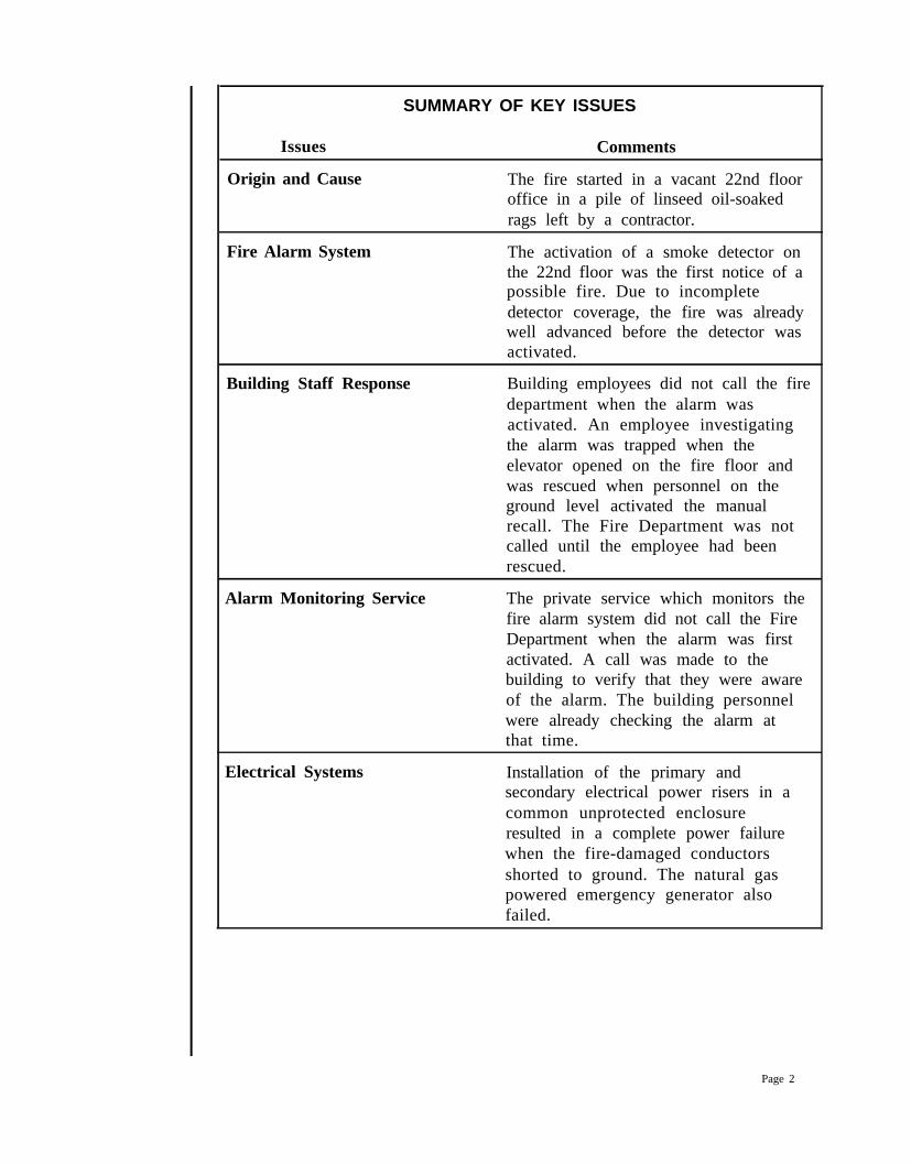
SUMMARY OF KEY ISSUES
Issues
Origin and Cause
Fire Alarm System
Comments
The fire started in a vacant 22nd flooroffice in a pile of linseed oil-soakedrags left by a contractor.
The activation of a smoke detector onthe 22nd floor was the first notice of apossible fire. Due to incompletedetector coverage, the fire was alreadywell advanced before the detector wasactivated.
Building Staff Response Building employees did not call the firedepartment when the alarm wasactivated. An employee investigatingthe alarm was trapped when theelevator opened on the fire floor andwas rescued when personnel on theground level activated the manualrecall. The Fire Department was notcalled until the employee had beenrescued.
Alarm Monitoring Service The private service which monitors thefire alarm system did not call the FireDepartment when the alarm was firstactivated. A call was made to thebuilding to verify that they were awareof the alarm. The building personnelwere already checking the alarm atthat time.
Electrical Systems Installation of the primary andsecondary electrical power risers in acommon unprotected enclosureresulted in a complete power failurewhen the fire-damaged conductorsshorted to ground. The natural gaspowered emergency generator alsofailed.
Page 2
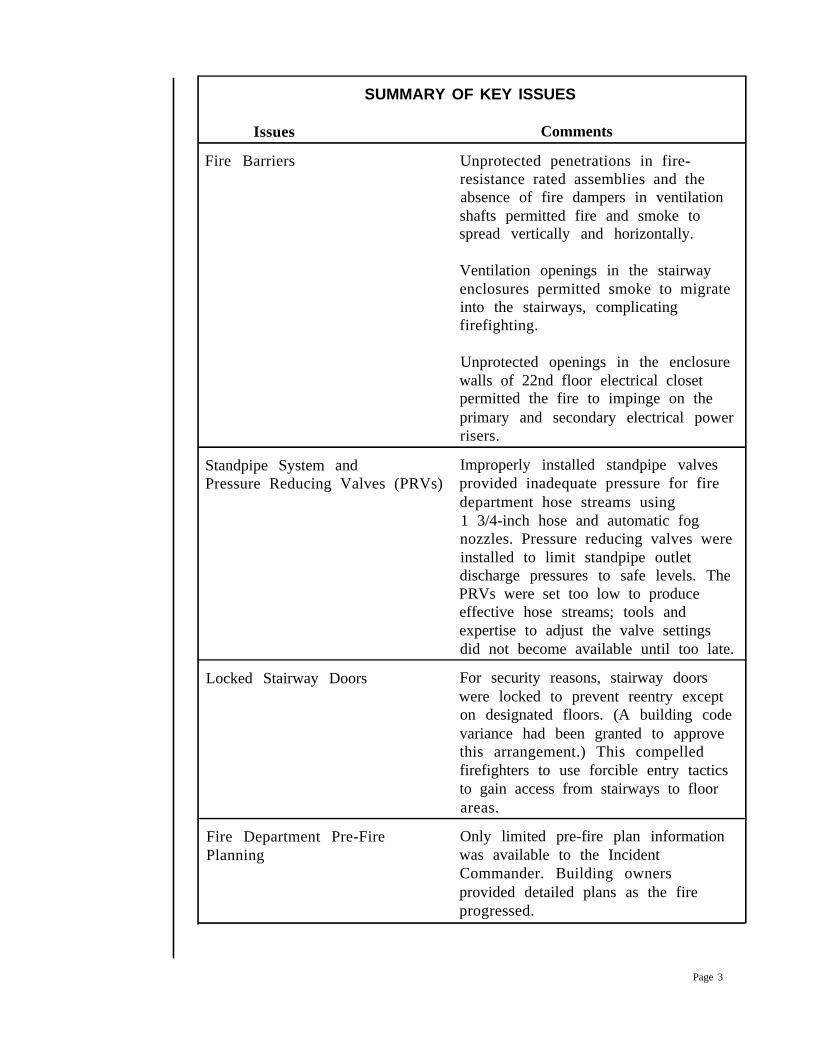
SUMMARY OF KEY ISSUES
Issues
Fire Barriers
Comments
Unprotected penetrations in fire-resistance rated assemblies and theabsence of fire dampers in ventilationshafts permitted fire and smoke tospread vertically and horizontally.
Ventilation openings in the stairwayenclosures permitted smoke to migrateinto the stairways, complicatingfirefighting.
Unprotected openings in the enclosurewalls of 22nd floor electrical closetpermitted the fire to impinge on theprimary and secondary electrical powerrisers.
Standpipe System and Improperly installed standpipe valvesPressure Reducing Valves (PRVs) provided inadequate pressure for fire
department hose streams using1 3/4-inch hose and automatic fognozzles. Pressure reducing valves wereinstalled to limit standpipe outletdischarge pressures to safe levels. ThePRVs were set too low to produceeffective hose streams; tools andexpertise to adjust the valve settingsdid not become available until too late.
Locked Stairway Doors For security reasons, stairway doorswere locked to prevent reentry excepton designated floors. (A building codevariance had been granted to approvethis arrangement.) This compelledfirefighters to use forcible entry tacticsto gain access from stairways to floorareas.
Fire Department Pre-FirePlanning
Only limited pre-fire plan informationwas available to the IncidentCommander. Building ownersprovided detailed plans as the fireprogressed.
Page 3
SUMMARY OF KEY ISSUES
Issues
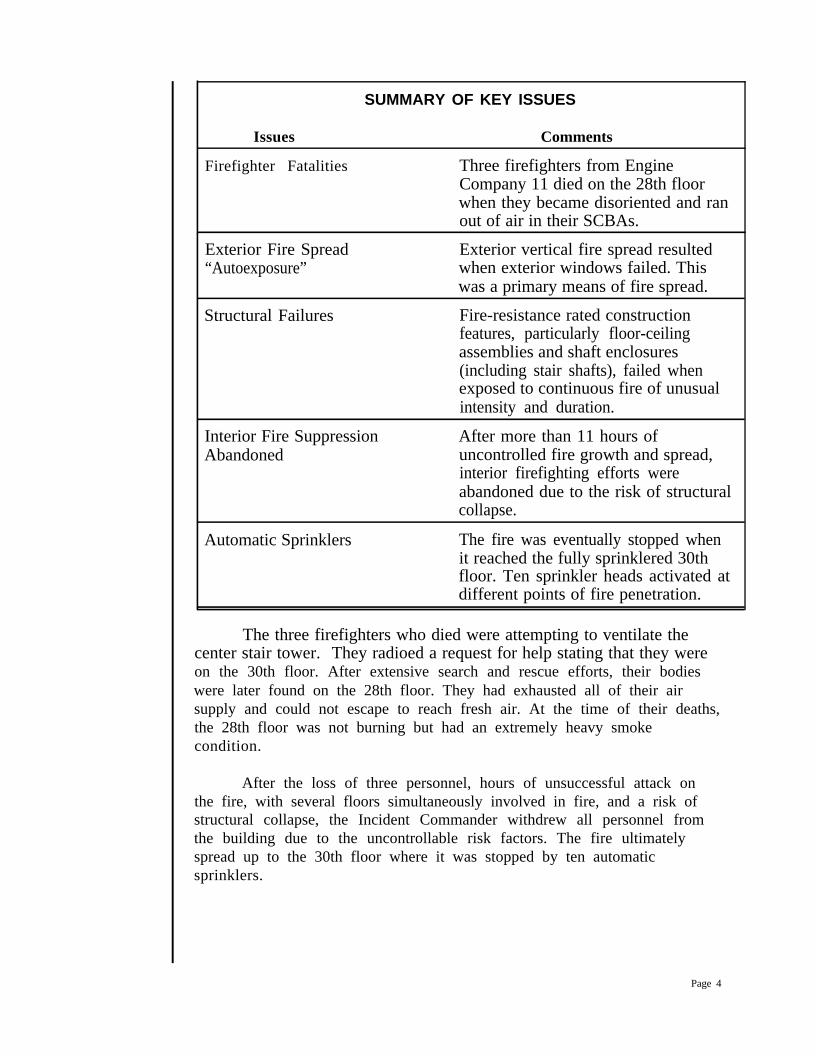
Firefighter Fatalities
Comments
Three firefighters from EngineCompany 11 died on the 28th floorwhen they became disoriented and ranout of air in their SCBAs.
Exterior Fire Spread“Autoexposure”
Exterior vertical fire spread resultedwhen exterior windows failed. Thiswas a primary means of fire spread.
Structural Failures Fire-resistance rated constructionfeatures, particularly floor-ceilingassemblies and shaft enclosures(including stair shafts), failed whenexposed to continuous fire of unusualintensity and duration.
Interior Fire SuppressionAbandoned
After more than 11 hours ofuncontrolled fire growth and spread,interior firefighting efforts wereabandoned due to the risk of structuralcollapse.
Automatic Sprinklers The fire was eventually stopped whenit reached the fully sprinklered 30thfloor. Ten sprinkler heads activated atdifferent points of fire penetration.
The three firefighters who died were attempting to ventilate thecenter stair tower. They radioed a request for help stating that they wereon the 30th floor. After extensive search and rescue efforts, their bodieswere later found on the 28th floor. They had exhausted all of their airsupply and could not escape to reach fresh air. At the time of their deaths,the 28th floor was not burning but had an extremely heavy smokecondition.
After the loss of three personnel, hours of unsuccessful attack onthe fire, with several floors simultaneously involved in fire, and a risk ofstructural collapse, the Incident Commander withdrew all personnel fromthe building due to the uncontrollable risk factors. The fire ultimatelyspread up to the 30th floor where it was stopped by ten automaticsprinklers.
Page 4
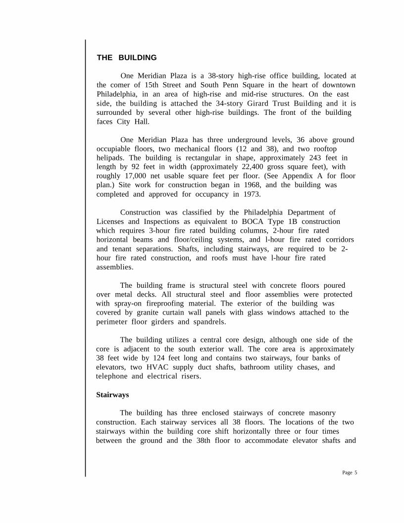
THE BUILDING
One Meridian Plaza is a 38-story high-rise office building, located atthe comer of 15th Street and South Penn Square in the heart of downtownPhiladelphia, in an area of high-rise and mid-rise structures. On the eastside, the building is attached the 34-story Girard Trust Building and it issurrounded by several other high-rise buildings. The front of the buildingfaces City Hall.
One Meridian Plaza has three underground levels, 36 above groundoccupiable floors, two mechanical floors (12 and 38), and two rooftophelipads. The building is rectangular in shape, approximately 243 feet inlength by 92 feet in width (approximately 22,400 gross square feet), withroughly 17,000 net usable square feet per floor. (See Appendix A for floorplan.) Site work for construction began in 1968, and the building wascompleted and approved for occupancy in 1973.
Construction was classified by the Philadelphia Department ofLicenses and Inspections as equivalent to BOCA Type 1B constructionwhich requires 3-hour fire rated building columns, 2-hour fire ratedhorizontal beams and floor/ceiling systems, and l-hour fire rated corridorsand tenant separations. Shafts, including stairways, are required to be 2-hour fire rated construction, and roofs must have l-hour fire ratedassemblies.
The building frame is structural steel with concrete floors pouredover metal decks. All structural steel and floor assemblies were protectedwith spray-on fireproofing material. The exterior of the building wascovered by granite curtain wall panels with glass windows attached to theperimeter floor girders and spandrels.
The building utilizes a central core design, although one side of thecore is adjacent to the south exterior wall. The core area is approximately38 feet wide by 124 feet long and contains two stairways, four banks ofelevators, two HVAC supply duct shafts, bathroom utility chases, andtelephone and electrical risers.
Stairways
The building has three enclosed stairways of concrete masonryconstruction. Each stairway services all 38 floors. The locations of the twostairways within the building core shift horizontally three or four timesbetween the ground and the 38th floor to accommodate elevator shafts and
Page 5
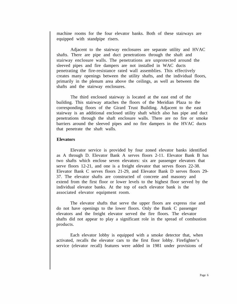
machine rooms for the four elevator banks. Both of these stairways areequipped with standpipe risers.
Adjacent to the stairway enclosures are separate utility and HVACshafts. There are pipe and duct penetrations through the shaft andstairway enclosure walls. The penetrations are unprotected around thesleeved pipes and fire dampers are not installed in WAC ductspenetrating the fire-resistance rated wall assemblies. This effectivelycreates many openings between the utility shafts, and the individual floors,primarily in the plenum area above the ceilings, as well as between theshafts and the stairway enclosures.
The third enclosed stairway is located at the east end of thebuilding. This stairway attaches the floors of the Meridian Plaza to thecorresponding floors of the Girard Trust Building. Adjacent to the eaststairway is an additional enclosed utility shaft which also has pipe and ductpenetrations through the shaft enclosure walls. There are no fire or smokebarriers around the sleeved pipes and no fire dampers in the HVAC ductsthat penetrate the shaft walls.
Elevators
Elevator service is provided by four zoned elevator banks identifiedas A through D. Elevator Bank A serves floors 2-11. Elevator Bank B hastwo shafts which enclose seven elevators: six are passenger elevators thatserve floors 12-21, and one is a freight elevator that serves floors 22-38.Elevator Bank C serves floors 21-29, and Elevator Bank D serves floors 29-37. The elevator shafts are constructed of concrete and masonry andextend from the first floor or lower levels to the highest floor served by theindividual elevator banks. At the top of each elevator bank is theassociated elevator equipment room.
The elevator shafts that serve the upper floors are express rise anddo not have openings to the lower floors. Only the Bank C passengerelevators and the freight elevator served the fire floors. The elevatorshafts did not appear to play a significant role in the spread of combustionproducts.
Each elevator lobby is equipped with a smoke detector that, whenactivated, recalls the elevator cars to the first floor lobby. Firefighter’sservice (elevator recall) features were added in 1981 under provisions of
Page 6
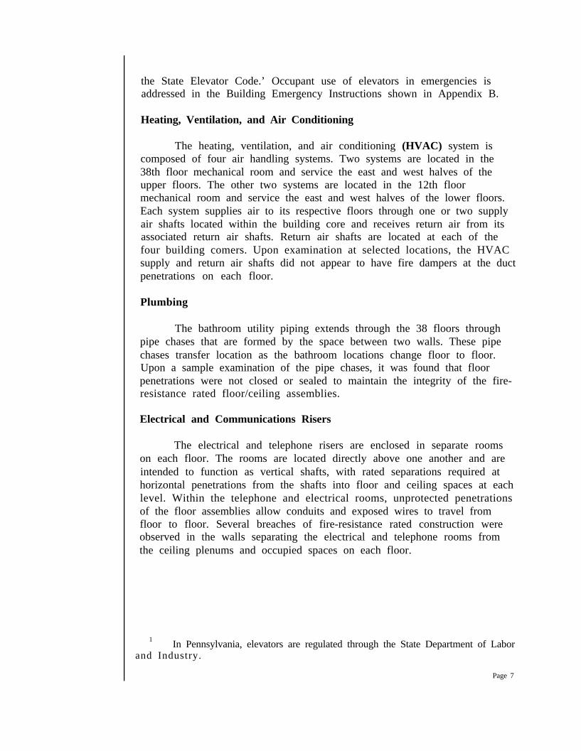
the State Elevator Code.’ Occupant use of elevators in emergencies isaddressed in the Building Emergency Instructions shown in Appendix B.
Heating, Ventilation, and Air Conditioning
The heating, ventilation, and air conditioning (HVAC) system iscomposed of four air handling systems. Two systems are located in the38th floor mechanical room and service the east and west halves of theupper floors. The other two systems are located in the 12th floormechanical room and service the east and west halves of the lower floors.Each system supplies air to its respective floors through one or two supplyair shafts located within the building core and receives return air from itsassociated return air shafts. Return air shafts are located at each of thefour building comers. Upon examination at selected locations, the HVACsupply and return air shafts did not appear to have fire dampers at the ductpenetrations on each floor.
Plumbing
The bathroom utility piping extends through the 38 floors throughpipe chases that are formed by the space between two walls. These pipechases transfer location as the bathroom locations change floor to floor.Upon a sample examination of the pipe chases, it was found that floorpenetrations were not closed or sealed to maintain the integrity of the fire-resistance rated floor/ceiling assemblies.
Electrical and Communications Risers
The electrical and telephone risers are enclosed in separate roomson each floor. The rooms are located directly above one another and areintended to function as vertical shafts, with rated separations required athorizontal penetrations from the shafts into floor and ceiling spaces at eachlevel. Within the telephone and electrical rooms, unprotected penetrationsof the floor assemblies allow conduits and exposed wires to travel fromfloor to floor. Several breaches of fire-resistance rated construction wereobserved in the walls separating the electrical and telephone rooms fromthe ceiling plenums and occupied spaces on each floor.
1In Pennsylvania, elevators are regulated through the State Department of Labor
and Industry.
Page 7
Emergency Power
The building electrical system receives power from two separateelectrical substations and is backed-up by an emergency generator. Thetwo sources of power are arranged so that the load would automaticallytransfer to the second source upon failure of the first. Electrical power forOne Meridian Plaza and four adjacent buildings is distributed from thebasement of 1414 S. Penn Square.
The electric service enters the building via the basement from theadjoining building and is distributed to the 12th and 38th floor mechanicalrooms via the electrical risers in the building core. From the 12th and 38thfloor mechanical rooms, electrical power is distributed to the majormechanical systems and to a buss bar riser, which services distributionpanels on the individual floors.
Emergency power was provided by a 340 kw natural gas-firedgenerator located in the 12th floor mechanical room. The generator wassized to supply power for emergency lighting and the fire alarm system, thefire pump located on the 12th floor and one car in each bank of elevators.The generator’s fuel was supplied by the building’s natural gas service.This generator was not required by the building code, since the building’selectrical power was supplied by two separate substations.
The generator was reported to have been tested weekly. The lastrecorded test date was January 30, almost four weeks before the fire, andthe maintenance records indicate that problems were encountered duringengine start-up under load conditions at that time. During a detailedinspection following that test, a damaged part was discovered and replaced.After the repair, the generator was started without a load and appeared towork properly, but no subsequent tests were performed to determine if theproblems persisted under load conditions.
Records of earlier maintenance and test activity suggest that loadtests were performed only occasionally. Test and maintenance recordsindicate a long history of maintenance problems with the emergencygenerator system. Many of these problems became manifest during orimmediately after conducting tests under load.
FIRE PROTECTION SYSTEMS
At the time of construction, the Philadelphia Building Coderequired only a local fire alarm system with manual stations at each exitand smoke detectors in the supply and return air shafts. Hose stations
Page 8
supplied from the domestic water service and portable fire extinguisherswere required for occupant use. Dry standpipes were installed for firedepartment use. Below ground levels were required to be provided withautomatic sprinklers.
As a result of local code changes, several improvements to the fireprotection systems were made in the years following the building’sconstruction.
In 1981, the Philadelphia Department of Licenses and Inspectionsimplemented amendments to the fire code which were intended to addressthe life safety of high-rise building occupants. These requirements includedinstallation of stair identification signs, provisions to permit stairway re-entry, and installation of smoke detection in common areas in the path ofaccess to exits. The “common areas” provision of the code was intended toaddress corridors and exit passageways in multi-tenant floors. The smokedetector requirements were interpreted in such a way that single tenant“open plan” floors were only required to have detectors installed at theexits; the entire floor, although open, was not considered a “common area.”Smoke detectors were also installed in the return air plenum adjacent tothe return air shaft intakes in each comer of the building. Theseprovisions required that building owners file permits for this work withinone year of the code change. City records do not indicate when this workwas performed in this particular building or if it was inspected andapproved.
Fire Detection and Alarm Systems
At the time of construction, One Meridian Plaza was equipped witha coded manual fire alarm system with pull stations installed adjacent toeach of the three exit stairwells on each floor. Smoke detection wasprovided in the major supply and return air ducts at the mechanical floorlevels.
After the 1981 fire code amendments were! enacted, the hardwareon stairway doors was required to allow access from stairs back to floorareas or to be unlocked automatically in the event that the fire alarm wasactivated. One Meridian Plaza was granted a variance from this provisionand generally had unlocked doors every three floors.
Approximately one and a half years before the fire, a public addresssystem was installed throughout the building. This system was operablefrom the lobby desk and had the capability of addressing floors, stairways,
Page 9
elevator machine rooms, and elevators. Two-way communication waspossible with elevators and elevator machine rooms.
As additional devices and systems were installed, they wereconnected to the fire alarm system to sound through the single-stroke bellsoriginally installed with the manual fire alarm system. Smoke detector andwater flow signals were assigned their own codes to allow annunciation notonly at the lobby but throughout the building for those members of thebuilding staff who knew the codes.
Standpipes
The occupant use standpipe system, which was connected to thedomestic water supply, provided two outlets per floor with 100 feet of1 l/2-inch hose and a nozzle. The hose cabinets were located in corridorson each floor.
A dry standpipe system was originally installed with 6 inch risers inthe west and center stair towers and outlets for 2 l/2 fire department hoselines at each floor level. This system was converted to a wet riser systemin 1988, to supply automatic sprinklers on some of the upper floors. An 8inch water supply was provided to deliver water to two 750 gpm electricfire pumps, one in the basement and one on the 12th floor.
The basement pump supplied the lower standpipe zone (floors B-12)while the 12th floor pump served the upper zone (floors 13-38).
There was no standpipe in the east stair tower.
A November 1988 Board of Building Standards decision permittedboth zones to be served by a common fire department connection, as partof a plan that would provide for the installation of automatic sprinklers onall floors by November 1993.2
Due to the height of the zones and the installation of fire pumps,pressures exceeded the 100 psi limit permitted by NFPA 14, Installation ofStandpipe and Hose Sytems at the standpipe hose outlets on several lowerfloors in each zone. Pressure restricting devices, which limit the dischargethrough standpipe outlets by restricting the orifice, were installed on themezzanine and second floor levels and on floors 26 through 30. Pressurereducing valves, which regulate both static pressure and discharge pressureunder variable flow conditions, were installed on floors 13 through 25.
2 Philadelphia Fire Department, “Investigative Report,” Section M, p. 2.
Page 10
Both types of devices prevent dangerous discharge pressures from hoseoutlets at the lower floors of each standpipe zone. The Philadelphia FireDepartment investigators report that the plans submitted at the time thestandpipes were converted did not indicate that PRVs were to be installed.
Automatic Sprinklers
Only the service floors located below grade were protected byautomatic sprinklers at the time of construction. Conversion of the drystandpipe to a wet system with fire pumps facilitated the installation ofautomatic sprinklers throughout the building. At the request of selectedtenants, sprinklers were installed on several floors during renovations,including all of the 3Oth, 31st, 34th, and 35th floors, and parts of floors 11and 15. Limited service sprinklers, connected to the domestic water supplysystem, were installed in part of the 37th floor. The building owners hadplans to install sprinklers on additional floors as they were renovated.
THE FIRE
Delayed Report
At approximately 2023 hours on February 23,1991, a smokedetector was activated on the 22nd floor of the One Meridian Plazabuilding. The activated detector is believed to have been located at theentrance to the return air shaft in the northeast comer of the building.At that time there were three people in the building, an engineer and twosecurity guards.’ The alarm sounded throughout the building and elevatorcars automatically returned to the lobby. The building engineerinvestigated the alarm using an elevator on manual control to go to the22nd floor. The central station monitoring company that served thebuilding reportedly called the guard desk in the lobby to report the alarm.The call came in before the engineer reached the fire floor, and the alarmcompany was told that the source of the alarm was being investigated. Thealarm company did not notify the Fire Department at that time.
When the elevator doors opened at the 22nd floor, the engineerencountered heavy smoke and heat. Unable to reach the buttons or toleave the elevator car to seek an exit, the building engineer becametrapped. He was able to use his portable radio to call the security guard at
3 The building staff regulated the after-hours population of the building through a lightingrequest system where tenants lights would be turned on for the duration of their work. Inaddition, there was a security system in the building that recorded any passage through stairwelldoors.
Page 11
the lobby desk requesting assistance. Following the trapped engineer’sinstructions, the security guard in the lobby recalled the elevator to theground floor using the Phase II firefighter’s safety feature.
The second security guard monitored the radio transmissions whiletaking a break on the 30th floor. This guard initially mistook the firealarm for a security alarm believing that he had activated a tenant’ssecurity system while making his rounds. He evacuated the building via thestairs when he heard the building engineer confirm there was a fire on the22nd floor.
The roving guard reported that as he descended from the 30th floorthe stairway was filling with smoke. He reached the ground level and metthe engineer and the other security guard on the street in front of thebuilding.
The Philadelphia Fire Department report on the incident states thatthe lobby guard called the alarm monitoring service to confirm that therewas an actual fire in the building when the engineer radioed to her fromthe 22nd floor. After meeting outside and accounting for each other’swhereabouts the three building personnel realized that they had not yetcalled the Fire Department.
The first call received by the Philadelphia Fire Department camefrom a passerby who used a pay telephone near the building to call 911.The caller reported smoke coming from a large building but was unable toprovide the exact address. While this call was still in progress, atapproximately 2027 hours, a call was received from the alarm monitoringservice reporting a fire alarm at One Meridian Plaza.
Initial Response
The Philadelphia Fire Department dispatched the first alarm at2027 hours consisting of four engine and two ladder companies with twobattalion chiefs. The first arriving unit, Engine 43, reported heavy smokewith fire showing from one window at approximately the mid-section of thebuilding at 2031 hours. A security guard told the first arriving battalionchief that the fire was on the 22nd floor. Battalion Chief 5 ordered asecond alarm at 2033 hours.
While one battalion chief assumed command of the incident at thelobby level, the other battalion chief organized an attack team to go up tothe fire floor. (The Philadelphia Fire Department’s “High-rise EmergencyProcedures” Operation Procedure 33 is presented in Appendix C.) The
Page 12
battalion chief directed the attack team to take the low-rise elevators upthe 11th floor and walk up from there.
Electrical Power Failure
Shortly after the battalion chief and the attack team reached the11th floor there was a total loss of electrical power in the building. Thisresulted when intense heat from the fire floor penetrated the electricalroom enclosure. The heat caused the cable insulation to melt resulting ina &ad short between the conductor and the conduit in both the primaryand secondary power feeds, and the loss of both commercial powersources. The emergency generator should have activated automatically, butit failed to produce electric power. These events left the entire buildingwithout electricity for the duration of the incident in spite of several effortsto restore commercial power and to obtain power from the generator.
This total power failure had a major impact on the firefightingoperations. The lack of lighting made it necessary for firefighters to carryout suppression operations in complete darkness using only batterypowered lights. Since there was no power to operate elevators, firefighterswere forced to hand carry all suppression equipment including SCBAreplacement cylinders up the stairs to the staging area that was establishedon the 20th floor. In addition, personnel had to climb at least 20 floors torelieve fellow firefighters and attack crews increasing the time required forrelief forces to arrive. This was a problem for the duration of the incidentas each relief crew was already tired from the long climb before they couldtake over suppression duties from the crews that were previouslycommitted.
Initial Attack
As the initial attack crews made their way toward the 22nd floorthey began to encounter smoke in the stairway. At the 22nd floor theyfound the west stair tower door locked. The door was already warped andblistering from the heat, and heavy fire could be seen through the door’swire glass window. A 1 3/4-inch hand line was stretched up the stairwayfrom a standpipe connection on the floor below and operated through thewindow while a ladder company worked on forcing open the door.
It took several minutes before the door could be forced open and anattempt could be made to advance onto the fire floor with the 13/4-inchattack line. The crews were not able to penetrate onto the 22nd floor dueto the intense heat and low water pressure they were able to obtain fromtheir hose line.
Page 13
An entry was also ma& on the 21st floor where the firefighterswere able to see fire on the floor above through the open conveniencestair. They attempted to use an occupant hose line to attack the fire butcould not obtain water from that outlet. They then connected a 1 3/4 inchattack line to the standpipe outlet in the stairway, but they could not obtainsufficient pressure to attack the flames. A Tactical Command Post wasestablished on the 21st floor and a staging area was set up on floor 20.
Fire Development
By this time fire was visible from several windows on the 22nd floorand crews outside were evacuating the area around the building andhooking up supply lines to the building’s standpipe connections. As flamesbroke through several more windows around a major portion of the firefloor, the floor above was subject to autoexposure from flames lapping upthe side of the building. Additional alarms were called to bring personneland equipment to the scene for a large scale fire suppression operation.
As the fire developed on the 22nd floor, smoke, heat, and toxicgases began moving through the building. Vertical fire extension resultedfrom unprotected openings in floor and shaft assemblies, failure of fire-resistance rated floor assemblies, and the lapping of flames throughwindows on the outside of the building.
Water Supply Problems
The normal attack hose lines used by the Philadelphia FireDepartment incorporate 1 3/4-inch hose lines with automatic fog nozzlesdesigned to provide variable gallonage at 100 psi nozzle pressure. Thepressure reducing valves in the standpipe outlets provided less than 60 psidischarge pressure, which was insufficient to develop effective fire streams.The pressure reducing values (PRVs) were field adjustable using a specialtool. However, not until several hours into the fire did a technicianknowledgeable in the adjustment technique arrive at the fire scene andadjust the pressure on several of the PRVs in the stairways.
When the PRVs were originally installed, the pressure settings wereimproperly adjusted. Index values marked on the valves did notcorrespond directly to discharge pressures. To perform adjustments thefactory and field personnel had to refer to tables in printed installation
Page 14
instructions to determine the proper setting for each floor level.4 Formore detailed information about PRVs see Appendices D and E.
Several fire department pumpers were connected to the FireDepartment connections to the standpipe system in an attempt to increasethe water pressure. The improperly set PRVs effectively prevented theincreased pressure in the standpipes from being discharged through thevalves. The limited water supply prevented significant progress in fightingthe fire and limited interior forces to operating from defensive positions inthe stairwells. During the next hour the fire spread to the 23rd and 24thfloors primarily through autoexposure, while firefighters were unable tomake entry onto these floors due to deteriorating heat and smokeconditions and the lack of water pressure in their hose lines. Windows onthe 22nd floor broke out and the 23rd and 24th floor windows were subjectto autoexposure from flames lapping up the sides of the building.
On the street below pedestrians were cleared from the area becauseof falling glass and debris as more and more windows were broken out bythe fire. Additional hose lines were connected to the standpipeconnections, attempting to boost the water pressure in the system.However, the design of the PRVs did not allow the higher pressures toreach the interior hose streams. Additional alarms were requested to bringa five-alarm assignment to the scene.
Three Firefighters Lost
As firefighters attempted to make entry to the burning floors fromthe stairways, heavy smoke continued to build up within the stair shafts andbanked down from the upper floors. An engine company was assigned toattempt to open a door or hatch to ventilate the stairways at the roof levelto allow the smoke and heat to escape. A Captain and two firefightersfrom Engine 11 started up the center stair from the 22nd floor with thisassignment. Engine 11 subsequently radioed that they had left the stairwayand were disoriented in heavy smoke on the 30th floor. Attempts weremade to direct the crew by radio to one of the other stairways.
Shortly thereafter a radio message was received at the CommandPost from Engine 11’s Captain requesting permission to break a windowfor ventilation. This was followed moments later by a message from a crew
4 The pressure reducing valves in the vicinity of the fire floor (floors 18 through 20)were set at “80” on the valve index which corresponded to a discharge pressure between 55 and57 psi, depending on the elevation. This would provide a nozzle pressure of 40 to 45 psi at theend of a 150 to 200 foot hose line.
Page 15
member of Engine 11 reporting that “the Captain is down.” Approval wasgiven to break the window and rescue efforts were initiated to search forthe crew. Search teams were sent from below and a helicopter wasrequested to land a team on the roof. The search teams were able toreach the 30th floor, which was enveloped in heavy smoke, but were unableto find the missing firefighters. They then searched the floors abovewithout success. An eight member search team became disoriented andran out of air in the mechanical area on the 38th floor, while trying to findan exit to the roof. They were rescued by the team that had landed on theroof and were transported back to ground level by the helicopter.
Several attempts were made to continue the search, until helicopteroperations on the rooftop had to be suspended due to the poor visibilityand the thermal drafts caused by the heat of the fire. The helicopter crewthen attempted an exterior search, using the helicopter’s searchlight, and at0117 located a broken window on the southeast comer of the 28th floor, inan area that could not be seen from any of the surrounding streets.Another rescue team was assembled and finally located the three missingmember just inside the broken window on the 28th floor at approximately0215. At that time the fire was burning on the 24th and 25th floors andextending to the 26th.
The victims were removed to the Medical Triage Area on the 20thfloor, but resuscitation efforts were unsuccessful and they were pronounceddead at the scene. An estimated three to four hours had elapsed sincethey had reported that they were in trouble and all had succumbed tosmoke inhalation.’
The three deceased members of Engine Company 11 were CaptainDavid P. Holcombe (age 52), Firefighter Phyllis McAllister (43), andFirefighter James A. Chappell (29).
Prior to being assigned to this task, the crew had walked up to thefire area wearing their full protective clothing and SCBAs and carryingextra equipment. It is believed that they started out with full SCBAcylinders, but it is not known if they became disoriented from the heavy
5 The exact time that Engine 11 was assigned to attempt ventilation and the time thecrew reported they were in trouble are not known, since the tactical radio channel they wereusing is not recorded and detailed time records of this event were not maintained during theincident. Estimates from individuals who were involved suggest that the assignment was madebetween 2130 and 2200 hours and search efforts were initiated between 2200 and 2230 hours.The bodies were located at approximately 0215 hours.
Page 16
smoke in the stairway, encountered trouble with heat build-up, or wereexhausted by the effort of climbing 28 floors. Some combination of thesefactors could have caused their predicament. Unfortunately, even afterbreaking the window they did not find relief from the smoke conditionswhich were extremely heavy in that part of the building.
Continuing Efforts to Improve Water Supply
Because of the difficulty in obtaining an adequate water supply, adecision was made to stretch 5-inch lines up the stairs to supply interiorattack lines. The first line was stretched up the west (#l) stairwell to the24th floor level and was operational by 0215, approximately six hours intothe fire. At 0221, a 12th alarm was sounded to stretch a second line, in thecenter (#2) stair. At 0455, a third 5-inch line was ordered stretched, in theeast (#3) stair. The operation in the east stair was discontinued at the17th floor level at 0600. While the 5-inch lines were being stretched, asprinkler contractor arrived at the scene and began manually adjusted thepressure reducing valves on the standpipe connections. This improved thedischarge pressure in the hoses supplied by the standpipe system, finallyproviding normal handline streams for the interior fire suppression crews.At this point, however, the fire involved several floors and could not becontained with manual hose streams.
Firefighting Operations Suspended
All interior firefighting efforts were halted after almost 11 hours ofuninterrupted fire in the building. Consultation with a structural engineerand structural damage observed by units operating in the building led tothe belief that there was a possibility of a pancake structural collapse ofthe fire damaged floors. Bearing this risk in mind along with the loss ofthree personnel and the lack of progress against the fire despite havingsecured adequate water pressure and flow for interior fire streams, anorder was given to evacuate the building at 0700 on February 24. At thetime of the evacuation, the fire appeared to be under control on the 22ndthough 24th floors. It continued to bum on floors 25 and 26 and wasspreading upward. There was a heavy smoke condition throughout most ofthe upper floors. The evacuation was completed by 0730.
After evacuating the building, portable master streams directed atthe fire building from several exposures, including the Girard Building #land One Centre Plaza, across the street to the west were the onlyfirefighting efforts left in place.
Page 17
Fire Stopped
The fire was stopped when it reached the 30th floor, which wasprotected by automatic sprinklers. As the fire ignited in different pointsthis floor level through the floor assembly and by autoexposure through thewindows, 10 sprinkler heads activated and the fires were extinguished ateach point of penetration. The vertical spread of the fire was stoppedsolely by the action of the automatic sprinkler system, which was beingsupplied by Fire Department pumpers. The 30th floor was not heavilydamaged by fire, and most contents were salvageable. The fire wasdeclared under control at 3:Ol p.m., February 24, 1991.
ANALYSIS
Smoke Movement
The heated products of combustion from a fire have a naturalbuoyancy, which causes them to accumulate in the upper levels of astructure. In a high-rise building the stairways, elevator shafts, and utilityshafts are natural paths for the upward migration of heated products ofcombustion.
Stack effect is a natural phenomenon affecting air movement in tallbuildings. It is characterized by a draft from the lower levels to the upperlevels, with the magnitude of the draft influenced by the height of thebuilding, the degree of air-tightness of exterior walls of the building, andtemperature differential between inside and outside air.6 This effect wasparticularly strong on the night of the fire due to the cold outsidetemperature. Interior air leakage rates, through shaft walls and openings,also modulate the rate of air flow due to stack effect. Smoke and toxicgases become entrained in this normal air movement during a fire and arecarried upward, entering shafts through loose building construction or pipeand duct penetrations. The air flow carries smoke and gases to the upperportions of the structure where the leakage is outward.
At the upper portions of the structure, smoke and toxic gasesfill the floors from the top floor down toward the fire, creating adangerous environment for building occupants and firefighters. During theinvestigation of this fire, this upward flow was evidenced by the presence ofheavy soot in the 38th floor mechanical room and all the upper floors of
6 Fitzgerald, R (1981), “Smoke Movement in Buildings,” in Fire ProtectionHandbook, 15th ed., McKinnon, G. P., ed., Quincy, MA: National Fire ProtectionAssociation, p. 3-32.
Page 18
the building. The path of smoke travel to the upper floors was vividlyevidenced by the soot remnants in HVAC shafts, utility chases, return airshafts, and exhaust ducts.
Fuel Loading
Fuel loading on the fire floors consisted mainly of files and papersassociated with securities trading and management consulting. At least onefloor had a significant load of computer and electronic equipment. Insome cases, correlation could be found between heavy fuel load anddamage to structural members in the affected area. From the 22nd floorto the 29th floor, the fire consumed all available combustible materialswith the exception of a small area at the east end of the 24th floor.
Structural Conditions Observed
Prior to deciding to evacuate the building, firefighters noticedsignificant structural displacement occurring in the stair enclosures. Acommand officer indicated that cracks large enough to place a man’s fistthrough developed at one point. One of the granite exterior wall panels onthe east stair enclosure was dislodged by the thermal expansion of the steelframing behind it. After the fire, there was evident significant structuraldamage to horizontal steel members and floor sections on most of the firedamaged floors. Beams and girders sagged and twisted -- some as much asthree feet -- under severe fire exposures, and fissures developed in thereinforced concrete floor assemblies in many places. Despite thisextraordinary exposure, the columns continued to support their loadswithout obvious damage.
INCIDENT COMMAND
During nearly 19 hours of firefighting, the Philadelphia FireDepartment committed approximately 316 personnel operating 51 enginecompanies, 15 ladder companies, and 11 specialized units, including EMSunits, to the 12-alarm incident. The incident was managed by 11 battalionchiefs and 15 additional chief officers under the overall command of theFire Commissioner. All apparatus and personnel were supplied withoutrequesting mutual aid. Off-duty personnel were recalled to staff reservecompanies to maintain protection for all areas of the city. Philadelphiauses an incident management system known within the department asPhiladelphia Incident Command (PIC). It is based on the ICS systemtaught at the National Fire Academy.
Page 19
Operations
The Department’s standard operating procedures for a high-riseincident were implemented at the time of arrival. Incident commanderswere confronted with multiple simultaneous systems failures. As a result,command and control decisions were based on the need to innovate and tofind alternate approaches to compensate for the normal systems thatfirefighters would have relied on to bring this incident to a more successfulconclusion.
Philadelphia Fire Department tactical priorities in a high-rise firefocus on locating and evacuating exposed occupants and making anaggressive interior attack to confine the fire to the area or at least the floorof origin. Confronted with total darkness, impaired vertical mobilitybecause the elevators were inoperable, water supply deficiencies whichmade initial attack efforts ineffective, vertical fire spread via unprotectedinterior openings and external auto-exposure, and worsening heat andsmoke conditions in the stairways, the tactical focus shifted to findingsomething (perhaps anything) which could be accomplished safely andeffectively.
When Engine 11’s crew reported their predicament, the prioritychanged to attempting to locate and rescue the trapped firefighters.Unfortunately, these efforts were in vain and nearly proved tragic when theeight firefighters conducting search and rescue operations becamedisoriented and ran out of air in the 38th floor mechanical room andnearly perished while trying to locate a roof exit. The rescue of thesemembers was extremely fortunate in a situation that could have resulted inan even greater tragedy.
Communications
As is often the case, communication at such a large incidentpresented a serious challenge to maintaining effective command andcontrol. The loss of electrical power plunged the entire building into totaldarkness, forcing firefighters to rely on portable lights. This impacted evenface-to-face communications by making it difficult for people to identifywith whom they were talking.
Radio communication was also affected by the significant durationof the incident. A field communications van was brought to the scene earlyin the incident with a supply of spare radios and batteries, but it was amajor challenge to provide charged batteries for all of the radios that werein use in the incident.
Page 20
To ease congestion on fireground radio channels, cellular telephoneswere used to communicate between the Command Post in the lobby andthe staging area on the 20th floor. Several other communications functionstook advantage of the cellular telephone capability.
Logistics
The Logistics Section was responsible for several functions includingrefilling SCBA cylinders, supplying charged radio batteries, and stretchingthe 5-inch supply line up the stairways. These were monumental endeavorswhich required the labor of approximately 100 firefighters. Equipment andsupplies were in constant demand including handlights and portablelighting, deluge sets, hose, nozzles and other equipment. The Staging Areaon the 20th floor included the Medical and Rehabilitation sectors.
The Philadelphia Fire Department used its high-rise air supplysystem to refill air cylinders on the 20th floor. Falling glass and debrissevered the airline, which is extended from the air compressor vehicleoutside the building to the staging area, and the system had to be repairedand reconnected at the scene.
Safety
When things go wrong on a scale as large as One Meridian Plaza,safety becomes an overriding concern. Firefighters were continuallyconfronted with unusual danger caused by multiple system failures duringthis incident. The deaths of the three firefighters and the critical situationfaced by the rescue team that was searching for them are clear evidence ofthe danger level and the difficulties of managing operations in a dark,smoke-filled high-rise building.
A perimeter was set up around the building to prevent injuries fromfalling glass and stone panels, but it was necessary for personnel to crossthis zone to enter and exit the building and to maintain the hose linesconnected to the standpipe system. One firefighter was seriously injuredwhen struck by falling debris while tending the hose lines. In addition, allsupplies and equipment needed inside the building had to cross the safetyperimeter at some point.
Many firefighters working inside the building were treated for minorinjuries and fatigue during the fire. Rest and rehabilitation sectorscontributed to firefighter safety by improving mental and physical stamina,and a medical triage treatment area was established on the 20th floor.
Page 21
The physical and mental demands on personnel were extraordinary.In addition to managing the physical safety of personnel, their emotionaland psychological well-being were considered. The Department activatedits critical incident stress debriefing program and relieved first and secondalarm companies soon after discovering that the crew of Engine 11 haddied on the 28th floor. More than 90 firefighters were debriefed on siteafter the dead firefighters were evacuated. The CISD involvementcontinued after the fire, due to the tremendous impact of the loss and therisk to the hundreds of firefighters who were involved in the incident.
The most courageous safety decision occurred when FireCommissioner Roger Ulshafer ordered the cessation of interior firefightingefforts and evacuated the building due to the danger of structural collapse.Firefighters did not reenter the structure until the fire had been controlledby the automatic sprinklers on the 30th floor and burned out all of theavailable fuels on the fire-involved lower levels.
BUILDING AND FIRE REGULATIONS
When One Meridian Plaza construction began in 1968, the City ofPhiladelphia was enforcing the 1949 edition of the Philadelphia BuildingCode. This code was of local origin and contained minor amendments thathad been incorporated since its enactment. This building code made nodistinction between high-rise and other buildings; and therefore, no specialhigh-rise construction features were required. The general focus of thecode was to provide a high degree of fire-resistive construction rather thanrelying on automatic sprinkler protection or compartmentation.
In 1984, Philadelphia switched from a locally developed buildingcode to one based on the BOCA Basic Building Code/l981. That code hassince been updated, and the BOCA National Building Code/1990 iscurrently in force in Philadelphia. Both of these codes contain provisionsexpressly addressing high-rise building fire protection, including arequirement for automatic sprinkler systems in all new high-rise buildings.
As a result of this fire, the City of Philadelphia has adopted anordinance requiring all existing high-rise buildings to be protected byautomatic sprinklers by 1997. Also, officials of the Philadelphia FireDepartment have discussed proposing adoption of the BOCA National FirePrevention Code with local amendments, as opposed to continuing todevelop their Philadelphia Fire Prevention Code locally.
Page 22
In 1981, the City enacted amendments to its Fire Code requiring theinstallation of special fire protection features in existing high-rise buildings.These modifications included:
Fire alarm systems with smoke detection in elevatorlobbies, entrances to exit stairways, return air plenums,corridors, and other common or public areas.
Stairway identification signs, (i.e., identification of thestairway, floor level, and the top and bottom levels ofthe stairway).
Stairway re-entry to permit occupants to retreat fromstairways compromised by smoke or fire and return totenant spaces. (In the event doors were locked fromthe stairway side for security reasons, provisions had tobe made to unlock doors automatically upon activationof the fire alarm system.)
In November 1984, the Philadelphia Department of Licenses andInspections issued a notice of violation to the owners of One MeridianPlaza requiring compliance with these amendments. The Board of Safetyand Fire Prevention later granted the owners a variance to permit stairwaydoors to be locked, provided that doors were unlocked to permit reentryevery third floor.7
FIRE CODE ENFORCEMENT
The preparation and adoption of fire safety regulations is managedby the Philadelphia Fire Department under the direction of the FireMarshal. However, the department does not perform or direct complianceinspections of individual properties. Fire code enforcement is delegated tothe Department of Licenses and Inspections (L&I) by city charter. Thisdepartment performs the functions of the building official in Philadelphia.
The Fire Department conducts inspections of properties applying forvariances, follows-up citizen complaints, and makes referrals to L&I. Theblock inspection program detailed in Fire Department OperationalProcedure 4 (see Appendix F) provides for the annual inspection of all
7 Records and reports provided by the Philadelphia Fire Department during this
investigation do not indicate the dates of either the appeal or this variance. Firefighters didreport having to force entry on several floors during firefighting because some stairwaydoors were locked.
Page 23
buildings except one and two family dwellings. However, Fire Departmentactivities to detect and abate hazards are primarily of an educationalnature. Guidelines for referring serious or continuing hazards to L&I arenot detailed in the Block Inspection procedure; however, informationregarding the maintenance of referral and appeal records for individualproperties is detailed.
It has been questioned whether the working relationship betweenline company personnel, the Fire Marshal’s office, and the Department ofLicenses and Inspections produces effective fire code compliance. SeniorFire Department officials have expressed considerable dissatisfaction withthe relationship between the Fire Department and L&I, and continue toadvocate a more active role for the Fire Department in code enforcementmatters.
Fire inspection records for One Meridian Plaza were examined afterthe fire to document code enforcement actions requiring the installation orupgrade of fire protection features required by the 1981 fire codeamendments. An August 17, 1990, L&I violation notice cited the ownerfor failing to pay a non-residential inspection fee and noted that areinspection would be conducted within 30 days. However, no record of asubsequent inspection was produced.
LESSONS LEARNED
Perhaps the most striking lesson to be learned from the OneMeridian Plaza high-rise fire is what can happen when everything goeswrong. Major failures occurred in nearly all fire protection systems. Eachof these failures helped produce a disaster. The responsibility for allowingthese circumstances to transpire can be widely shared, even by those notdirectly associated with the events on and before February 23, 1991.
To prevent another disaster like One Meridian Plaza requireslearning the lessons it can provide. The consequences of this incident arealready being felt throughout the fire protection community. Major codechanges have already been enacted in Philadelphia (see Appendix G) andnew proposals are under consideration by the model code organizations.These changes may eventually reduce the likelihood of such a disaster inmany communities.
Page 24
1. Automatic sprinklers should be the standard level of protection inhigh-rise buildings.
The property conservation and life safety record of sprinklers isexemplary, particularly in high-rise buildings. While other fire protectionfeatures have demonstrated their effectiveness over time in limiting lossesto life and property, automatic sprinklers have proven to provide superiorprotection and the highest reliability. Buildings in some of the nation’slargest cities, designed and built around effective compartmentation, havedemonstrated varying success at containing fires, but their effectiveness isoften comprised by inadequate design or installation and may not beeffectively maintained for the life of the building. Even with effectivecompartmentation, a significant fire may endanger occupants and require amajor commitment of fire suppression personnel and equipment.Retrofitting of automatic sprinklers in existing buildings has proveneffective in taking the place of other systems that have been found to beinadequate.
2. Requirements for the installation of automatic sprinklers arejustified bv concerns about firefighter safetv and public protectioneffectiveness. as well as traditional measures such as life safety andproperty conservation.
The property protection value of sprinklers was recognized longbefore life safety became a popular justification for installing fireprotection. Life safety has become the primary concern in recent times,justifying the installation of automatic sprinklers in high-rise buildings. Thevalue of sprinklers as a means of protecting firefighters has rarely beendiscussed.
Members of the fire service should promote automatic firesprinklers if for no other reason than to protect themselves. Requiring theinstallation and maintenance of built-in fire protection should become alife safety issue for firefighters.8 The opposition to retrofit protection hasconsistently cited cost concerns. Communities need to be made aware thatthe costs they defer may be paid by firefighters in terms of their safety.This is above and beyond the potential loss to citizens and businesses thatis usually considered.
8 A study by Charles Jennings reports that the firefighter injury rate in non-sprinkleredhigh-rise buildings is seven times higher than in comparable buildings equipped with automaticsprinklers. “In High-rise Fire Sprinklers Beat Compartmentation -Hands Down.” U.S. FireSprinkler Reporter, April 1992, pp. 1, 5-7.
Page 25
3. Code assumptions about fire department standpipe tactics movedinvalid.
One of the principal code assumptions affecting fire departmentoperations at One Meridian Plaza concerned the installation of standpipepressure reducing valves. The rationale for PRVs is the concern thatfirefighters would be exposed to dangerous operating pressures and forces
Firefighters at One Meridian Plaza had great difficultydetermining how to improve flow and pressure from hose outlets duringthe fire. Even if firefighters could have closely examined the valves,with good light and under less stressful conditions, it is unlikely thatthey would have been able to readjust the valves. Numerical indicatorson the valve stems represented an index for adjustment not the actualdischarge pressure. (This may have confused the techniciansresponsible for installing and maintaining the valves. Investigatorsfound valves set at “20” and “80” on the index markings. To achieve 65psi would have required a setting from 88 to 91 on the index. A settingof 150 to 158 was necessary to produce the maximum allowable 100psi.)
Pressure regulating devices come in three different types:
Pressure restricting devices which reduce pressureunder flowing conditions by reducing the cross-sectional area of the hose outlet.
Pressure control valves are pilot-operated deviceswhich use water pressure within the system tomodulate the position of a spring-loadeddiaphragm within the valve to reduce downstreampressure under flowing and non-flowing conditions.
Pressure reducing valves use a spring-loaded valveassembly to modulate the position of the valve discin the waterway to reduce the downstream pressureunder flowing and non-flowing conditions.
Further differentiation within each of these types results fromdifferences in manufacturer specifications. (Details are provided in thePhiladelphia Fire Department fact sheet on pressure regulating devicesin Appendix G.) Some devices are field adjustable, some are not.Some can be removed to permit full, unrestricted flow, others cannot.
Page 26
if they connected hose lines to outlets near the base of standpipe risers ofsubstantial height, particularly those supplied by stationary fire pumps. Forexample, in a 275 foot high standpipe zone (the highest permitted usingstandard pipe and fittings), a pressure of 184 psi is required at the base of theriser to overcome elevation and produce the minimum required outlet pressureof 65 psi at the top of the riser. At this pressure, a standard 2 1/2-inch firehose fitted with a 1 1/8-inch straight bore nozzle would produce a backpressure (reaction force) in excess of 500 pounds. This is a well-foundedconcern; however, it is built upon the assumption that fire departments use2 1/2-inch attack lines and straight bore nozzles to attack fires fromstandpipes. Most fire departments today use 1 3/4-inch and 2-inch hosewith fog nozzles for interior attack. These appliances require substantiallygreater working pressures to achieve effective hose streams.
In the aftermath of this incident, the NFPA Technical Committeeon Standpipes has proposed a complete revision of NFPA 149 to moreclosely reflect current fire department operating practices. Section 5-7 ofthe proposed standard requires a minimum residual pressure of 150 psi atthe required flow rate from the topmost 2 1/2-inch hose outlet and 65 psiat the topmost 1 1/2-inch outlet (presumably for occupant use). Minimumflow rates of 500 gpm for the first standpipe and 250 gpm for eachadditional standpipe remain consistent with past editions of the standard.The proposed new requirements limit the installation of pressure regulatingdevices to situations where static pressures at hose outlets exceed 100 psifor occupant use hose or 175 psi for fire department use hose. This willprovide substantially greater flow and pressure margins for fire departmentoperations. These requirements are intended to apply to new installationsand are not retroactive.
4. The requirements and procedures for design. installation. inspection,testing. and maintenance of standpipes and oressure reducing valves mustbe examined carefully.
The proposed revision of NFPA 14 (1993) and a new NFPAdocument, NFPA 25, Standard for the Installation, Testing, and Maintenanceof Water-Based Fire Protection Systems (1992), address many of the concernsarising from this fire regarding installation and adjustment of pressurereducing valves. NFPA 14 requires acceptance tests to verify properinstallation and adjustment of these devices. NFPA 25 requires flow testsat five year intervals to verify proper installation and adjustment.
9The report of the Technical Committee on Standpipes appears in the NFPA I992
Fall Meeting Technical Committee Reports, pp. 331-367.Page 27
Neither of these standards proposes changes in the performancestandards for the design of pressure reducing valves.
Standard performance criteria for the design and operation of eachtype of valve should be adopted to encourage user-friendly designs that willpermit firefighters to achieve higher pressure and flow rates withoutinterrupting firefighting operations. The operation and adjustment ofvalves should be easy to identify and clearly understandable by inspectionand maintenance personnel without reliance on detailed operating ormaintenance instructions.
It is extremely important to have all systems and devices thoroughlyinspected and tested at the time of installation and retested on a regularbasis. Fire suppression companies that respond to a building should befamiliar with equipment that is installed in its fire protection systems andconfident that it will perform properly when needed.
5. Inconsistencies between code assumptions and firefighting; tacticsmust be addressed.
The inconsistency between fire department tactics and designcriteria for standpipe hose outlet pressures was widely recognized beforethis fire. However, little was done to change fire department tactics or toamend the code requirements for standpipe installations.
Fire departments utilize lightweight hose and automatic nozzles forthe same reasons the code requires pressure reducing valves: firefightersafety. The inconsistency between these approaches can cause seriousproblems. Where pressure reducing valves are not installed, firedepartments can usually augment water supplies by connecting to the firedepartment connections. However, when contemporary firefighting tacticsare employed and improperly adjusted PRVs are installed, the combinationis likely to produce hose streams with little reach or effectiveness.
The PRV equipped hose outlets on the 22nd floor of One MeridianPlaza, adjusted as reported at the time of the fire, would have producednozzle pressures of approximately 40 psi. This is insufficient for a straightstream device and dangerously inadequate for a fog nozzle.
Standard operating procedures for high-rise buildings, particularlythose not protected by automatic sprinklers, should reflect the potentialneed to employ heavy firefighting streams, which may require higher flowsand pressures.
Page 28
6. Pre-fire planning is an essential fire department function.
The availability of information about the building was a problem inthis incident.
The purpose of conducting pre-fire plans is be to gather informationabout buildings and occupancies from the perspective that a fire willeventually occur in the occupancy. This information should be used toevaluate fire department readiness and resource capabilities. At a firescene, pre-fire plan information can be used to formulate strategies fordealing with the circumstances which present themselves.
Pre-fire planning activities should identify building and fireprotection features which are likely to help or hinder firefightingoperations and record this information in a format usable to firefighters atthe scene of an emergency. Recognizing and recording information aboutpressure restricting devices and pressure reducing valves should be amongthe highest priorities. Information on fire alarm systems and auxiliaryfeatures such as elevator recall, fan control or shutdown, and door releasesshould also be noted.
The Fire Department was unable to obtain important details aboutthe installed fire protection at One Meridian Plaza during critical stages ofthe fire attack. Detailed information about the design and installation ofstandpipes, pressure relief valves and the fire pump, could have aidedfirefighters significantly if it had been available earlier in the fire.
Pre-fire plans and standard operating procedures should alsoconsider evacuation procedures and plans for the removal of occupants.
7. Standard Operating Procedures (SOPS) and training programs forfires in high-rise buildings should reflect the installed protection and high-rise fire behavior.
Training and SOPS should consider ways to achieve adequate fireflow with available pressures and ways to improve flow and pressure whenrequired. Tactics for placing multiple lines in service simultaneously mustalso be developed and discussed.
Extensive pre-fire planning and training are required for firedepartment control of mechanical smoke management systems to beeffective. Training in the management of smoke should consider stackeffect and the ability to predict and/or direct ventilation in a real incident.
Pag e 29
8. Safety-oriented strategies should dominate command decisions whenmultiple systems failures become evident.
This incident presented command officers with an unprecedentedsequence of system failures. As more things went wrong, officers had toseek alternative approaches to manage the situation. The time pressureand stress of fireground command can make it difficult to thoroughlyevaluate each alternative approach, particularly as new and unanticipatedproblems are presented in rapid succession. Conservative tactics, orientedtoward protecting the firefighters who must execute them, should takeprecedence when confronted with an unknown and unanticipated situation,since the potential consequences of fireground decisions can rarely be fullyevaluated during the incident. As much as possible, these alternativesshould be considered beforehand in pre-fire planning, standard operatingprocedures, and training materials, and by reviewing post-fire critiques andreports of other incidents. This is an incident that will make a majorcontribution to the knowledge of what can and will happen when majorsystem failures occur in the worst imaginable sequence.
9. Fire code enforcement programs require the active participation ofthe fire department.
In Philadelphia, responsibility for the fire code is fragmented. TheFire Department is responsible for developing and maintaining fire coderequirements, supervising the appeals process, and investigating andreferring fire code complaints. However, it does not conduct regularperiodic code enforcement inspections, issue permits, or develop targethazard protocols for ensuring that inspections conducted by the responsibleagency are addressing critical fire protection problems.
Many of the model code requirements that apply to high-risebuildings are predicated upon assumptions about firefighting strategies andtactics. Most model code organizations designate the fire department, fireprevention bureau, or fire marshal’s office as the principal enforcementauthority for fire protection system requirements. Fire departmentpersonnel are in the best position to validate code assumptions and seethat the built-in fire protection and life safety systems are functional andcompatible. Moreover, the first-hand knowledge and experience offirefighters with fire behavior is often an invaluable resource wheninterpreting fire and building code requirements.
Page 30
10. Code provisions should be adopted requiring high-rise buildingowners to retain trained personnel to manage fire protection and life safetycode compliance and assist fire department personnel during; emergencies.
Model fire prevention codes require building owners to develophigh-rise fire safety and evacuation plans to manage the life safetycomplexities of these buildings. The requirements are not specific aboutwhat must be included in these plans, and they give no explicitconsideration to the problems of firefighting and property conservation.
Mandating the appointment and certification of individuals withspecialized knowledge in code requirements and building systems would goa long way toward ensuring that the unique aspects of each high-risebuilding are incorporated into detailed plans.
(New York City Local Law 5 requires that each owner designate afire safety director. The responsibilities of this individual for managing thelife safety plan during an incident are clearly established in this ordinance.)
11. Occupants and central station operators must always treat automaticfire alarms as though they were actual fires. especially in high-risebuildings.
Building personnel, alarm services, and fire departments mustdevelop an expectation that an automatic alarm may be an indication of anactual fire in progress. Automatic detection systems have gained areputation for unnecessary alarms in many installations. This has causedan attitude of complacency that can be fatal in responding to such alarms.To change such attitudes and expectations, it will be necessary to improvethe reliability and performance of many systems.
By choosing to investigate and verify the alarm condition, the buildingengineer nearly lost his life. If not for the ability to communicate with thelobby guard to relay instructions for manually recalling the elevator, thisindividual would likely have shared the fate of his counterpart who died in aservice elevator at the First Interstate Bank Building Fire in Los Angeles (May4, 1988).
Technological advances and improved maintenance procedures arethe answers to solving the nuisance alarm problem. In addition torequiring regular maintenance of systems by qualified individuals,Philadelphia and other cities have stiffened the penalties on owners,occupants, and central station operators who fail to report automatic firealarm activations.
Page 31
12. Incomplete fire detection can create a false sense of security.
Automatic fire detectors, like automatic sprinklers, are componentsof engineered fire protection systems. A little protection is not alwaysbetter than none. Over-reliance on incomplete protection may lead to afalse sense of security on the part of building owners and firefighters alike.
Automatic fire detectors can only notify building occupants orsupervisory personnel at a central, remote, or proprietary station that anevent has occurred, and in some cases initiate action by other systems tolimit the spread of fire, smoke, or both. (In this case, automatic detectorsinitiated an alarm, recalled elevators, and shutdown air handlingequipment; however an elevator was subsequently used to go to the firefloor to investigate the alarm.)
Smoke detectors at One Meridian Plaza were installed in particularareas as required by the 1981 amendments to the fire code; that is at thepoint of access to exits, at the intakes to return air shafts, and in elevatorlobbies and corridors. The apparent underlying logic was to protect themeans of egress and to detect smoke in the areas where it was most likelyto travel. It appears in this case that the partitions and suspended ceilingcontained the smoke and heat during the fire’s incipient phase andprevented early detection. In all likelihood, the first detector may not haveactivated until after the room of origin had flashed-over. Shortly afterflashover, the suspended ceiling in this area probably failed permitting thefire to spread throughout the return air plenum. Once the fire broke theexterior windows and established an exterior air supply there was little thatcould be done to control the fire. Firefighters were disadvantaged by thedelay in reporting the fire.
13. Nationally recognized elevator code requirements for manualcontrol of elevators during fire emergencies work.
Elevator control modifications at One Meridian Plaza wereaccomplished in accordance with Commonwealth of Pennsylvaniarequirements based on ANSI/ASME A17.1, Safety Code for Elevators andEscalators. The elevators performed as expected by the standard. Theonly problem with the elevator response was the decision of the buildingengineer to override the system to investigate the alarm.
Page 32
14. The ignition source provided by oil-soaked rags is a lone recognizedhazard that continues to be a problem.
Had the contractor refinishing paneling on the 22nd floor notcarelessly left oil soaked cleaning rags unattended and unprotected in avacant office, this fire would not have occurred. To pinpoint the particularsource of ignition of this fire as the sole cause of the death and destructionthat followed is a gross oversimplification. Nevertheless, failure to controlthis known hazard is the proximate cause of this disaster. The danger ofspontaneous heating of linseed oil-soaked rag waste is widely recognized.Each model fire prevention code requires precautions to prevent ignition ofsuch materials. At a minimum, waste awaiting removal from the buildingand proper disposal must be stored in metal containers with tight-fitting,self-closing lids. Leaving these materials unattended in a vacant office overa weekend was an invitation to disaster. This is both an education and anenforcement problem for fire prevention officials.
15. Building security personnel should be vigilant for fire safety as wellas security threats, especially while construction, demolition. alteration, orrepair activities are underway.
Earlier in the day, the building engineer had become aware of anunusual odor on the 22nd floor which he associated with the refinishingoperations which were underway there. When the alarm system activatedlater that evening he first believed the solvent vapors had activated asmoke detector.
The roving security guard made no mention of anything unusualduring his rounds of the fire area earlier in the evening. It is conceivablethat no detectable odor of smoke or audible or visible signals of a fire werepresent when the guard last checked the floor. However, a cursory checkis not adequate when construction, demolition, renovations, or repairactivities are underway in a building area. Fire hazards are oftenassociated with construction activities, and buildings are especiallyvulnerable to fire during such operations. For these reasons, it should bestandard practice to check these areas even more carefully and thoroughlythan usual. All building operating and security personnel should have basictraining in fire prevention and procedures to be followed when a fireoccurs.
Page 33
16. Emergency electrical systems must be truly independent orredundant.
Article 700 of the National Electrical Code recognizes separatefeeders as a means of supplying emergency power. However, Section700-12(d) requires these services to be “widely separated electrically andphysically...to prevent the possibility of simultaneous interruption ofsupply.” Installing the primary and secondary electrical risers in a commonenclosure led to their almost simultaneous failure when the fire penetratedvoids in the walls above the ceiling of the 22nd floor electrical closet. Theintense heat melted conductor insulation resulting in dead shorts to groundwhich opened the overcurrent protection on each service interruptingpower throughout the building.
Auxiliary emergency power capability was provided by a natural gaspowered generator located in the basement mechanical room. Thisgenerator was intended to supply one elevator car in each bank, firepumps, emergency lighting and signs, and the fire alarm system. However,this generator set failed to produce power when needed. (Generatormaintenance records indicated a history of problems; however, the rootcause or mechanism responsible for these problems was not identified.)
Supplying the generator from the building natural gas service alsoleft the emergency power system vulnerable in the event of simultaneousfailure of the electrical and gas public utilities. The transformers thatprovided power for the adjacent building were installed in the basement ofthe One Meridian Plaza Building. These transformers had to be shut downdue to the accumulation of water in the basement, resulting in the loss ofpower to this building as well. As a result the elevators in the adjoiningbuilding could not be used.
17. The regulations governing fire-resistance ratings for high-risestructural components should be re-evaluated.
The degree of structural damage produced during the fire at OneMeridian Plaza suggests that the requirements for structural fire resistanceshould be reexamined. Floor assemblies deflected as much as three feet insome places. The fire burning on multiple floors may have producedsimultaneous exposure of both sides of these assemblies, which consisted ofconcrete slabs on corrugated decks, supported by structural steel beam andgirder construction, sprayed with cementitious fireproofing materials. Thestandard fire test for floor and ceiling assemblies involves exposure from asingle side only.
Page 34
Columns and certain other structural elements are normally exposedto fire from all sides. In this fire, the steel columns retained theirstructural integrity and held their loads. Experience in this and similarhigh-rise fires suggest that columns are the least vulnerable structuralmembers, due to their mass and relatively short height between restraints(floor to floor). Major damage has occurred to horizontal members,without compromising the vertical supports.
The development of uniform criteria for evaluating structural fireendurance accompanied the development of skyscrapers in the early 20thcentury. Test methods developed at the beginning of the century becamethe first fire-resistance standard in 1909,10 which endures today as ASTME119, Method of Fire Test of Building Construction and Materials. One ofthe principal criticisms of this standard has been its lack of correlation withactual fire conditions.
Many fire protection professionals believe that the standard time-temperature curve used to produce the standard fire exposure duringtesting is less severe than actual fires involving contemporary fuel loads.(The original test method was based on less volatile, primarily cellulosic,fuels, while modem plastics and hydrocarbon-based furnishings and finishesproduce much more dangerous and severe fire exposures.) Others believethat the current test method works well because it provides a goodyardstick for comparing the performance of different systems and has beenin widespread use for many decades, generating volumes of data on manysystems1
18. Inspections must be conducted during: and after construction toverify that penetrations in fire-resistance rated assemblies are properlyprotected.
Voids and so-called poke-throughs in horizontal and vertical fireseparation assemblies presented ideal avenues of fire spread during theOne Meridian Plaza fire. Openings in the partitions enclosing electrical
10 Fitzgerald, R W. (1981), “Structural Integrity During Fire,” in Fire ProtectionHandbook, 15th ed., McKinnon, G. P., ed., Quincy, MA: National Fire ProtectionAssociation, p. 5-62.
11 Actual conditions in most fires produce heat release curves similar to the standardexposure up to the point where oxygen, i.e., ventilation, becomes restricted by fire productrelease, i.e., smoke and heated gases. However, at this point, actual fires usually diminish insize unless ventilation improves or a renewed oxygen supply is established. Once refreshed witha new air supply, most fires will resume growth, reach a peak, and then diminish as the fuelsupply is consumed.
Page 35
equipment on the floor of origin permitted the fire to reach and damagethe electrical risers, plunging firefighters into darkness early in the fire.Voids in stairwell enclosures permitted smoke to spread in stairwellsmaking firefighting operations difficult and exposing upper floors. Smokeand fire also extended via pipe chases, and telephone and electrical closets.
Through-penetration protection has been a continuing concern andhas received considerable attention in building and fire codes in recentyears. Each of the model building codes now contains provisions requiringprotection of poke-throughs in fire-resistance rated assemblies. Moreover,a whole new industry has been developed to fill the technological void inthrough-penetration protection which developed with the widespreadacceptance of plastic pipe and cable.
The absence of fire dampers in mechanical system supply and returnducts at shaft penetrations on each floor is of particular concern. There isevidence of smoke and fire spread through the air handling system.Nationally recognized model building, fire, and mechanical codes havecontained requirements for fire dampers in these locations for many years.The installation of smoke detectors in these locations was an ineffectivesubstitute for protecting the integrity of smoke and fire barriers. This fireclearly illustrates that smoke and fire spread through mechanical systemplenums, ducts, and shafts is substantial even without the aid of operatingfans.12
19. Features to limit exterior vertical fire spread must be incorporatedin the design of high-rise buildings.
Exterior vertical fire spread or autoexposure can be a significant fireprotection problem in construction of high-rise buildings if interior firegrowth is unrestricted. Because of the difficulty with retrofitting exteriorfeatures to restrict fire spread, the installation of automatic sprinklers torestrict fire growth is the most simple approach to managing this risk inexisting buildings. Exterior features to prevent fire spread must usually bedesigned and built into new buildings. Many modem (international style)and post-modem building designs present difficult exterior fire spreadchallenges because of their smooth exterior facades and large glazing areas.Variegated exterior facades and larger noncombustible spandrelssignificantly reduce exterior fire spread effects by increasing the distanceradiant and conductive heat must travel to stress exterior windows and toheat materials inside the windows on floors above the fire.
1 2 HVAC fans were shut down at night and on weekends, and were not operating atthe time of the fire.
Page 36
CONCLUSION
The ultimate message delivered by this fire is the proof thatautomatic sprinklers are the most effective and reliable means at ourdisposal to protect high-rise buildings. When all other systems failed,automatic sprinklers were successful in controlling the fire. ThePhiladelphia Fire Department was confronted with an essentiallyimpossible situation and did a commendable job of managing the incident.The loss of three firefighters is a tragedy that will always be rememberedby the Philadelphia Fire Department. Analysis of the situation reveals,however, that the toll could have been much worse, had it not been for thecourage, skills, and experience of this Department. Several extremelydifficult decisions were made under the most severe conditions. This firewill also be remembered for the lessons that it brings with respect to fireprotection systems. To work effectively, such systems must be properlydesigned, installed, and maintained. When those requirements are notsatisfied, the results can be devastating, as clearly demonstrated by thisincident.
Page 37
SOURCES OF INFORMATION
In addition to references to codes and standards cited in the text,news media accounts of the fire, and interviews with officials of thePhiladelphia Fire Department, the following resources were used in thepreparation of this report:
Alert Bulletin: Pressure Regulating Devices in Standpipe Systems (May1991). Quincy, MA: National Fire Protection Association.
Butters, T., and T. Elliott (March 1991). “How the Philadelphia FDHandled the Worst High-Rise Fire in the City’s History,” IAFC OnScene, March 15, 1991.
Eisner, H., and B. Manning (August 1991). “One Meridian Plaza Fire,”Fire Engineering, August 1991. pp. 50-70.
Factory Mutual Engineering Corporation (March 1990). High-RiseBuildings, Loss Prevention Data Sheet l-3. Boston, MA: FactoryMutual Engineering Corporation.
Factory Mutual Engineering Corporation (December 1986). PressureReducing Valves for Fire Protection Service, Loss Prevention DataSheet 3-11. Boston, MA: Factory Mutual Engineering Corporation.
Klem, T. J. (May 1991). Preliminary Investigative Report: One MeridianPlaza, Philadelphia, PA, February 23, 1991, Three Fire FighterFatalities. Quincy, MA: National Fire Protection Association-
Klem, T. J. (September/October 1991). “High-Rise Fire Claims ThreePhiladelphia Fire Fighters,” NFPA Journal, Sept/Oct 1991. pp. 64-67, 89.
Linville, J. L., ed. (1991). Fire Protection Handbook, 17th ed. Quincy, MA:National Fire Protection Association.
McKinnon, G. P., ed. (1981). Fire Protection Handbook, 15th ed. Quincy,MA: National Fire Protection Association.
One Meridian Plaza: 12-Alarm High-Rise Fire (1991), Philadelphia, PA:Philadelphia Fire Films. Videotape.
Page 38
A P P E N D I C E S
A.
B.
C.
D.
E.
F.
G.
Elevation Drawing of the Building and 22nd Floor Plan, Floor ofFire Origin
Building Emergency Instructions
Philadelphia Fire Department High-rise Emergency Procedures
Factory Mutual Engineering Corporation Pressure Reducing ValveLess Prevention Data Sheet
Philadelphia Fire Department Pressure Regulating Device FactSheet
Philadelphia Fire Department Block Inspection Program
Philadelphia Fire Code Amendments Adopted after the OneMeridian Plaza Fire
H. Photographs
Appendix A
Elevation Drawing of the Building and22nd Floor Plan, Floor of Origin
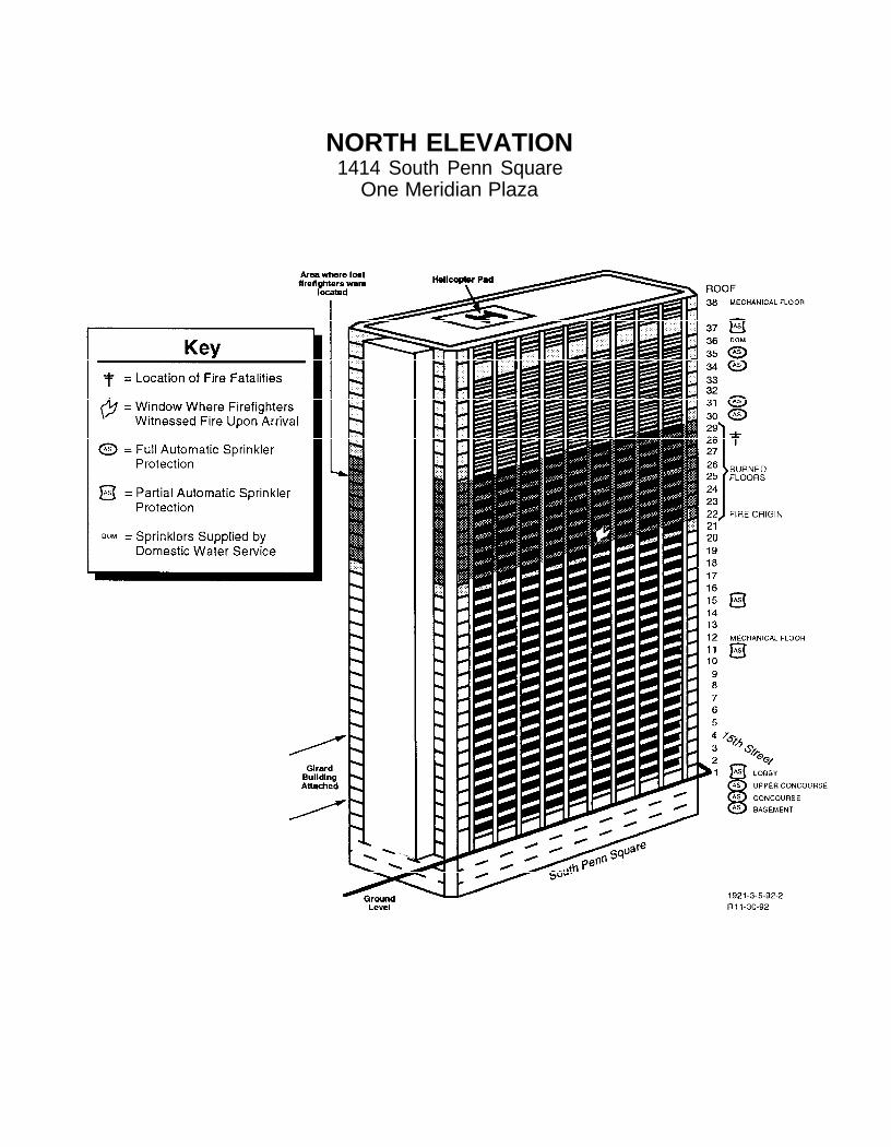
NORTH ELEVATION1414 South Penn Square
One Meridian Plaza
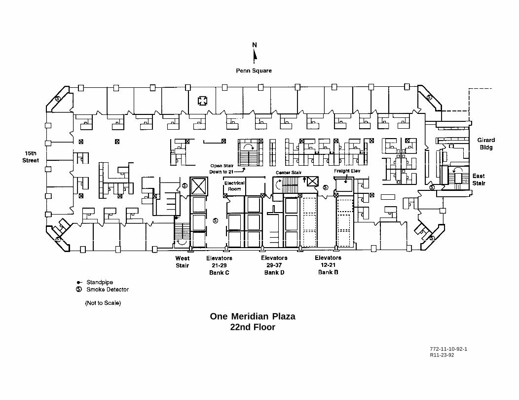
One Meridian Plaza22nd Floor
772-11-10-92-1R11-23-92

Appendix B
Building Emergency Instructions
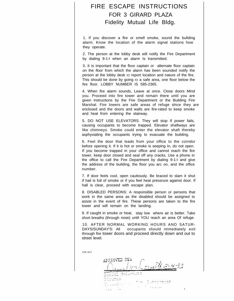
FIRE ESCAPE INSTRUCTIONSFOR 3 GIRARD PLAZA
Fidelity Mutual Life Bldg.
1. If you discover a flre or smell smoke, sound the bulldingalarm. Know the location of the alarm signal stations how they operate.
2. The person at the lobby desk will notify the Fire Departmentby dialing 9-1-l when an alarm Is transmitted.
3. It is important that the floor captain or alternate floor captainon the floor from which the alarm has been sounded notify theperson at the lobby desk IO report location and nature of the fire.This should be done by going IO a safe area, one floor below thefire floor. LOBBY NUMBER IS 585-2365.
4. When fire alarm sounds, Leave at once. Close doors Mindyou. Proceed into fire tower and remain there until you aregiven instructions by the Fire Department or the Building FireMarshal. Fire lowers are safe areas of refuge slnce they areenclosed and the doors and walls are fire-rated to keep smokeand heat from entering the stairway.
5. DO NOT USE ELEVATORS. They will stop If power fails,causing occupants to become trapped. Elevator shaftways arelike chimneys. Smoke could enter the elevator shaft therebyasphyxiating the occupants trying to evacuate the building.
6. Feel the door that leads from your office to the corridorbefore opening it. If it is hot or smoke is seeping In, do not open.If you become trapped in your office and cannot reach the firetower, keep door closed and seal off any cracks. Use a phone inthe office to call the Fire Department by dialing 9-1-l and givethe address of the building, the floor you arc on, and the officenumber.
7. If door feels cool, open cautiously. Be braced to slam it shutif hail is full of smoke or if you feel heat pressrure against door. Ifhall is clear, proceed with escape plan.
8. DISABLED PERSONS: A responsible person or persons thatwork in the same area as the disabled should be assigned toassist in the event of fire. These persons are taken to the firetower and will remain on the landing.
9. If caught in smoke or heat, stay low where air is better. Takeshort breaths (through nose) until YOU reach an area Of refuge.
10. AFTER NORMAL WORKlNG HOURS AND SATUR-DAYS/SUNDAY'S: All occupants should immediately exitthrough fire tower doors and proceed directly down and out tostreet level.
O M - 8 4 7
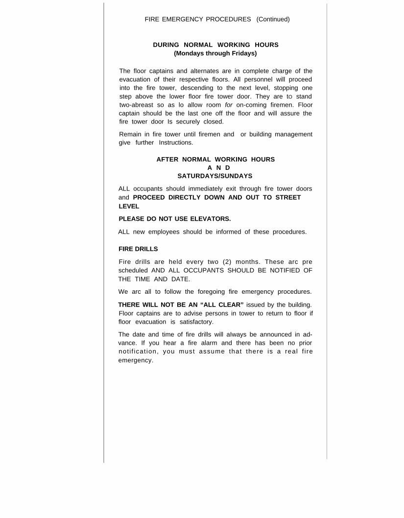
FIRE EMERGENCY PROCEDURES (Continued)
DURING NORMAL WORKING HOURS(Mondays through Fridays)
The floor captains and alternates are in complete charge of theevacuation of their respective floors. All personnel will proceedinto the fire tower, descending to the next level, stopping onestep above the lower floor fire tower door. They are tO standtwo-abreast so as lo allow room for on-coming firemen. Floor
captain should be the last one off the floor and will assure thefire tower door Is securely closed.
Remain in fire tower until firemen and or building managementgive further Instructions.
AFTER NORMAL WORKING HOURSA N D
SATURDAYS/SUNDAYS
ALL occupants should immediately exit through fire tower doorsand PROCEED DIRECTLY DOWN AND OUT TO STREETLEVEL
PLEASE DO NOT USE ELEVATORS.
ALL new employees should be informed of these procedures.
FIRE DRILLS
Fire drills are held every two (2) months. These arc prescheduled AND ALL OCCUPANTS SHOULD BE NOTIFIED OFTHE TIME AND DATE.
We arc all to follow the foregoing fire emergency procedures.
THERE WILL NOT BE AN “ALL CLEAR” issued by the building.Floor captains are to advise persons in tower to return to floor iffloor evacuation is satisfactory.
The date and time of fire drills will aIways be announced in ad-vance. If you hear a fire alarm and there has been no priornot i f icat ion, you must assume that there is a real f i reemergency.

Appendix C
Philadelphia Fire DepartmentHigh-rise Emergency Procedures
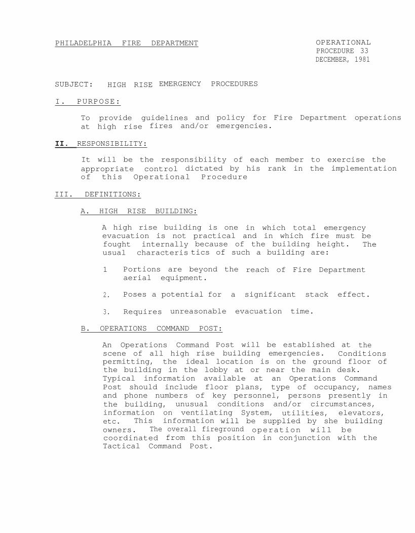
PHILADELPHIA FIRE DEPARTMENT OPERATIONALPROCEDURE 33DECEMBER, 1981
SUBJECT: HIGH RISE EMERGENCY PROCEDURES
I. PURPOSE:
To provide guidelines and policy for Fire Department operationsat high rise fires and/or emergencies.
II. RESPONSIBILITY:
It will be the responsibility of each member to exercise theappropriate control dictated by his rank in the implementationof this Operational Procedure
III. DEFINITIONS:
A. HIGH RISE BUILDING:
A high rise building is one in which total emergencyevacuation is not practical and in which fire must befought internally because of the building height. Theusual characteris tics of such a building are:
1 Portions are beyond the reach of Fire Departmentaerial equipment.
2. Poses a potential for a significant stack effect.
3. Requires unreasonable evacuation time.
B. OPERATIONS COMMAND POST:
An Operations Command Post will be established at thescene of all high rise building emergencies. Conditionspermitting, the ideal location is on the ground floor ofthe building in the lobby at or near the main desk.Typical information available at an Operations CommandPost should include floor plans, type of occupancy, namesand phone numbers of key personnel, persons presently inthe building, unusual conditions and/or circumstances,information on ventilating System, utilities, elevators,etc. This information will be supplied by she buildingowners. The overall fireground operation will becoordinated from this position in conjunction with theTactical Command Post.
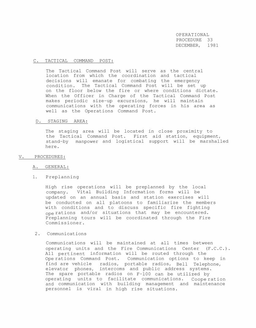
OPERATIONALPROCEDURE 33DECEMBER, 1981
C. TACTICAL COMMAND POST:
The Tactical Command Post will serve as the centrallocation from which the coordination and tacticaldecisions will emanate for combating the emergencycondition. The Tactical Command Post will be set upon the floor below the fire or where conditions dictate.When the Officer in Charge of the Tactical Command Postmakes periodic size-up excursions, he will maintaincommunications with the operating forces in his area aswell as the Operations Command Post.
D. STAGING AREA:
The staging area will be located in close proximity tothe Tactical Command Post. First aid station, equipment,stand-by manpower and logistical support will be marshalledhere.
V. PROCEDURES:
A. GENERAL:
1. Preplanning
High rise operations will be preplanned by the localcompany. Vital Building Information forms will beupdated on an annual basis and station exercises willbe conducted on all platoons to familiarize the memberswith conditions and to discuss specific fire fightingope rations and/or situations that may be encountered.Preplanning tours will be coordinated through the FireCommissioner.
2. Communications
Communications will be maintained at all times betweenoperating units and the Fire Communications Center (F.C.C.).A11 pertinent information will be routed through theOpe rations Command Post. Communication options to keep infind are vehicle radios, portable radios, Bell Telephone,elevator phones, intercoms and public address systems.The spare portable radios on F-100 can be utilized byoperating units to facilitate communications. Coope rationand communication with building management and maintenancepersonnel is viral in high rise situations.
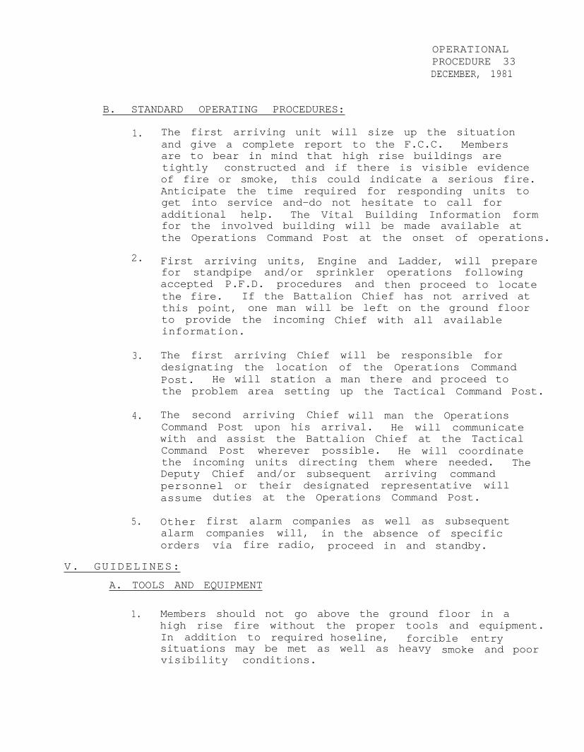
OPERATIONALPROCEDURE 33DECEMBER, 1981
B. STANDARD OPERATING PROCEDURES:
1.
2.
3.
4.
5.
The first arriving unit will size up the situationand give a complete report to the F.C.C. Membersare to bear in mind that high rise buildings aretightly constructed and if there is visible evidenceof fire or smoke, this could indicate a serious fire.Anticipate the time required for responding units toget into service and-do not hesitate to call foradditional help. The Vital Building Information formfor the involved building will be made available atthe Operations Command Post at the onset of operations.
First arriving units, Engine and Ladder, will preparefor standpipe and/or sprinkler operations followingaccepted P.F.D. procedures and then proceed to locatethe fire. If the Battalion Chief has not arrived atthis point, one man will be left on the ground floorto provide the incoming Chief with all availableinformation.
The first arriving Chief will be responsible fordesignating the location of the Operations CommandPost. He will station a man there and proceed tothe problem area setting up the Tactical Command Post.
The second arriving Chief will man the OperationsCommand Post upon his arrival. He will communicatewith and assist the Battalion Chief at the TacticalCommand Post wherever possible. He will coordinatethe incoming units directing them where needed. TheDeputy Chief and/or subsequent arriving commandpersonnel or their designated representative willassume duties at the Operations Command Post.
Other first alarm companies as well as subsequentalarm companies wil1, in the absence of specificorders via fire radio, proceed in and standby.
V. GUIDELINES:
A. TOOLS AND EQUIPMENT
1. Members should not go above the ground floor in ahigh rise fire without the proper tools and equipment.In addition to required hoseline, forcible entrysituations may be met as well as heavy smoke and poorvisibility conditions.
OPERATIONALPROCEDURE 33DECEMBER, 1981
2. An engine company's high rise tool compliment willconsist of the following equipment:
a. Standpipe adapters for particular buildings.
b. Three (3) rolled lengths of l-3/4" hose with shutoff.
C. A gated-wye or half of- the reducing adapter.
d. Roof rope.
B. STAIRWAYS:
1. Every effort should be made to maintain the integrityof stairways and towers, as these are main evacuationroutes. Doors leading into these exitways should notbe propped open, as the introduction of smoke and heatinto these avenues of life safety might preclude theiruse.
In the event a stairway or tower is to be used,considaration must be given to prior evecuation ofthe upper floors, where required, or the availabilityof another means of egress, remote from the area ofinvolvement.
2. Towers are good locations to initiate fire attack asstandpipes are usually located there and an escaperoute is readily available.
C. ELEVATORS:
1. The location and status of all elevators should bedetermined early in the operation, because of thepossibility of people being trapped in stalled ele-vators. Every effort should be made to return allelevators to the ground floor so they can be con-trolled by Fire Department personnel.
2 . The manual over- ride key will be obtained at the lobbyconsole or from the building engineer. Freightelevators are best suited for P.F.D. operations, inthat, they usually serve all floors and have greatercarrying capacity. Where possible, elevator banksremote from the fire should be utilized.
OPERATIONALPROCEDURE 33DECEMBER, 1981
3. If there is any doubt about the safe use of elevators,members will utilize stairways and towers.
D. OPERATIONAL CONSIDERATIONS:
1. Ventilation
a. Building personnel may be able to indicate whatinternal mechanical ventilation can be affected.Frequently, ventilating systems can be reversedto exhaust smoke. If details of the systemcannot be determined, air conditioning andventilating systems should be shut down to curtailthe spread of smoke and heated gases throughoutthe building.
b. Smoke ejectors properly utilized can be of greatvalue in channeling smoke. Window air conditionersmay be of value in the exhaust position.
C. Breaking glass on the upper floors of a high risebuilding is an extremely risky practice. Even ifpolice lines are maintained, glass falling fromextreme heights could carry over long distancescausing serious injury to both civilian and FireDepartment personnel. Glass should be broken onlyas a last resort.
VI. EVACUATION.
A. RESPONSIBILITY:
The building owner or manager will have the responsi-bility of preparing an evacuation plan for the highrise building occupants and/or tenants, with theassistance of the Fire Prevention Division. The highrise building Fire Marshal will have the initial re-sponsibility of occupant movement in a fire emergencyand may order total evacuation, if conditions warrant,before the arrival of the P.F.D.
3. PROCEDURES TO FOLLOW:
1. In buildings with two or more fire towers, all buildingoccupants will enter the fire tower and line thestairway at the sounding of the building fire alarm.prepared to evacuate. When the location of the fire isconfirmed, P.F.D. personnel will. institute the removaland relocation of building occupants in these firetowers. Occupants will be assisted to refuge areasbelow the fire floor.
2.
3.
4.
5.
OPERATIONALPROCEDURE 33DECEMBER, 1981
a. When the occupant load is such that the fire towerswill not accommodate all of the occupants, theinitial evacuation into the fire towers will be thefire floor and two floors above the fire floor,before the arrival of the P.F.D.
In buildings with one interior enclosed fire tower orbuildings that have only open stairways, totalevacuation will be started by the Building Fire Marshal.Upon arrival, the Commanding Officer will determine theneed for continued and/or total evacuation.
In buildings of newer construction that possess thecapability of pressurizing individual floors and ele-vator shafts, the building Fire Marshal will institutea three floor evacuation plan. The building fire alarm,when activated, will sound on the fire floor, the floorabove the fire floor and the floor below. The occupantson the affected floors will proceed into the fire towersand line the stairway. A warning tone will sound on theremaining floors when the alarm is activated and theoccupants on these floors will stand by their-assignedfire tower for further instructions, via the publicaddress system, by the building Fire Marshal or theFire Officer in charge. At the sounding of the alarm,the building engineer will shut down the air handlingsystem on the fire floor and pressurize the floor abovethe fire floor and elevator shafts.
In all high rise hotels and motels, the owner or managerwill supply written evacuation procedures for the hotelguests which will be posted on the inside of each guestroom door, and the elevator lobby at each level. Whenhotel guests are taken to a refuge area, at least onemember from the P.F.D. will remain with the guests andinform them when they may return to their rooms.
The first arriving fire officer will obtain the list ofall disabled persons at the lobby console or from thebuilding Fire Marshal. It will be necessary for P.F.D.members to assist the disabled persons from the firetower t0 the ground floor, if partial or tota1 evacuationis necessary. This can be accomplished by using elevatorsremote from the fire area. This procedure will includeall high rise hotels.
REFERENCE: High Rise Fire Safety Training ManualPhiladelphia Fire Code - Chapter 5-3400 High Rise Building.
BY ORDER OF THE FIRE COMMISSIONER

Appendix D
Factory Mutual Engineering CorporationPressure Reducing Valve Loss Prevention Data Sheet
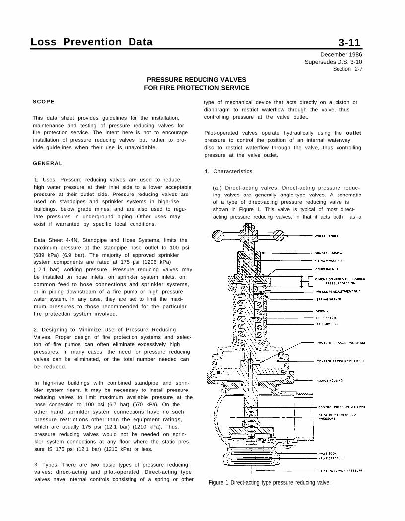
Loss Prevention Data
PRESSURE REDUCING VALVESFOR FIRE PROTECTION SERVICE
3-11December 1986
Supersedes D.S. 3-10Section 2-7
S C O P E
This data sheet provides guidelines for the installation,
maintenance and testing of pressure reducing valves forfire protection service. The intent here is not to encourageinstallation of pressure reducing valves, but rather to pro-vide guidelines when their use is unavoidable.
GENERAL
1. Uses. Pressure reducing valves are used to reducehigh water pressure at their inlet side to a lower acceptablepressure at their outlet side. Pressure reducing valves areused on standpipes and sprinkler systems in high-risebuildings. below grade mines, and are also used to regu-late pressures in underground piping. Other uses mayexist if warranted by specific local conditions.
Data Sheet 4-4N, Standpipe and Hose Systems, limits themaximum pressure at the standpipe hose outlet to 100 psi(689 kPa) (6.9 bar). The majority of approved sprinklersystem components are rated at 175 psi (1206 kPa)(12.1 bar) working pressure. Pressure reducing valves maybe installed on hose inlets, on sprinkler system inlets, oncommon feed to hose connections and sprinkler systems,or in piping downstream of a fire pump or high pressurewater system. In any case, they are set to limit the maxi-mum pressures to those recommended for the particularfire protectlon system involved.
2. Designing to Minimize Use of Pressure ReducingValves. Proper design of fire protection systems and selec-ton of fire pumos can often eliminate excessively highpressures. In many cases, the need for pressure reducingvalves can be eliminated, or the total number needed canbe reduced.
In high-rise buildings with combined standpipe and sprin-kler system risers. it may be necessary to install pressurereducing valves to limit maximum available pressure at thehose connection to 100 psi (6.7 bar) (670 kPa). On theother hand. sprinkler system connections have no such
pressure restrictions other than the equipment ratings,whlch are usually 175 psi (12.1 bar) (1210 kPa). Thus.pressure reducing valves would not be needed on sprin-kler system connections at any floor where the static pres-sure IS 175 psi (12.1 bar) (1210 kPa) or less.
3. Types. There are two basic types of pressure reducingvalves: direct-acting and pilot-operated. Direct-acting typevalves nave Internal controls consisting of a spring or other
type of mechanical device that acts directly on a piston ordiaphragm to restrict waterflow through the valve, thuscontrolling pressure at the valve outlet.
Pilot-operated valves operate hydraulically using the outletpressure to control the position of an internal waterwaydisc to restrict waterflow through the valve, thus controllingpressure at the valve outlet.
4. Characteristics
(a.) Direct-acting valves. Direct-acting pressure reduc-ing valves are generally angle-type valves. A schematicof a type of direct-acting pressure reducing valve isshown in Figure 1. This valve is typical of most direct-acting pressure reducing valves, in that it acts both as a
Figure 1 Direct-acting type pressure reducing valve.
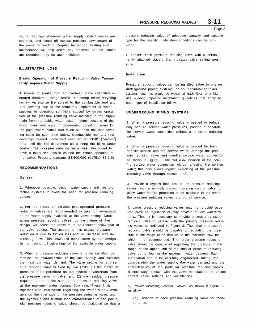
PRESSURE REDUCING VALVES 3-11Page 3
pressure reducing valve of adequate capacity and suitabletype for the specific installation conditions can be pro-vided.
gauge readings whenever water supply control valves areoperated, and bleed off excess pressure downstream ofthe pressure reading. Regular Inspection, testing and
maintenance will help detect any problems so that immedi-
ate remedies may be accomplished.
ILLUSTRATlVE LOSS
Erratic Operation of Pressure Reducing Valve Tempo-
rarily impairs Water Supply.
A shower of sparks from an overhead crane railignited oil-coated titanium turnings inside this scrap metal recyclingfacility. An intense fire spread to the combustible roof androof covering due to the temporary impairment of watersupplies to operating sprinklers caused by erratic opera-tion of the pressure reducing valve installed in the supplymain from the public water system. Many sections of thewood plank roof were in deteriorated condition, some lothe point where planks had fallen out, and the roof cover-
ing could be seen from below. Combustible roof and roofcoverings burned unchecked over an 80,000-ft2 (7440-m2)area until the fire department could bring the blaze undercontrol. The pressure reducing valve was later found tohave a faulty seal. which caused the erratic operation ofthe valve. Property damage S3,500,000 (01751X-81-1-8)
RECOMMENDATIONS
General
1. Whenever possible, design water supply and fire pro-tection systems to avoid the need for pressure reducingvalves.
2. For fire protection service, pilot-operated pressurereducing valves are recommended to take full advantageof the water supply available at the valve setting. Direct-acting pressure reducing valves, by the nature of theirdesign. will cause the pressure to be reduced below that ofthe valve setting. The amount of this excess pressurereduction is due to friction loss and will increase with in-creasing flow. This drawback complicates system designby not taking full advantage of the available water supply.
3. When a pressure reducing valve is to be installed. de-termine the characteristics of the inlet supply and calculatethe maximum water demand. The valve setting for a pres-sure reducing valve IS fixed by two limits: (1) the maximum
pressure lo be permitted on the system downstream fromthe pressure reduclng valve: and (2) the residual pressurerequired on the outlet side of the pressure reducing valveat the maximum water demand flow rate. These limits,together with information regarding the water supply avail-able on the inlet side of the pressure reducing valve. andthe hydraulic and frlction loss characeristics of the partic-ular pressure reducing valve. should be evaluated so that a
4. Provide each pressure reducing valve with a perma-nently attached placard that indicates valve setting pres-
sure.
Installation
Pressure reducing valves can be installed either in pits onunderground piping systems. or on individual sprinklersystems. such as would be typical at each floor of a high-rise building. Specific installation guidelines that apply toeach type of installation follow.
UNDERGROUND PIPING SYSTEMS
1. When a pressure reducing valve is needed to reduceonly non-fire service water pressures, provide a separatefire service water connection without a pressure reducingvalve.
2. When a pressure reducing valve is needed for bothnon-fire service and fire service water, arrange the pres-sure reducing valve and non-fire service water connectionas shown in Figure 3. This will allow isolation of the non-fire service water connection without affecting fire servicewater; this also allows regular exercising of the pressurereducing valve through normal draft.
3. Provide a bypass loop around the pressure reducingvalves. with a normally closed indicating control valve, toallow water for fire protection to be available in the eventthe pressure reducing valves are out of service.
4. Large pressure reducing valves may not provide accu-rate pressure regulation or may cavitate at low waterflowrates. Thus, it is necessary to provide a smaller pressurereducing valve in parallel with the primary pressure reduc-ing valve, as indicated in Figure 3. The smaller pressurereducing valve should be capable of regulating the pres-sure in the range of no flow up to the maximum flow forwhich it is recommended. The larger pressure reducingvalve should be capable of regulating the pressure in therange of the upper limit of the smaller pressure reducingvalve up to flow for the maximum water demand. Eachinstallation should be carefully engineered. taking intoconsideration the water supply, the water demand and thecharacteristics of the particular pressure reducing valves.If necessary. consult with the valve manufacturer lo ensurecorrect valve settings and installations.
5. Provide indicating control valves as shown in Figure 3to allow
(a.) Isolatlon of each pressure reduclng valve for main-renance.
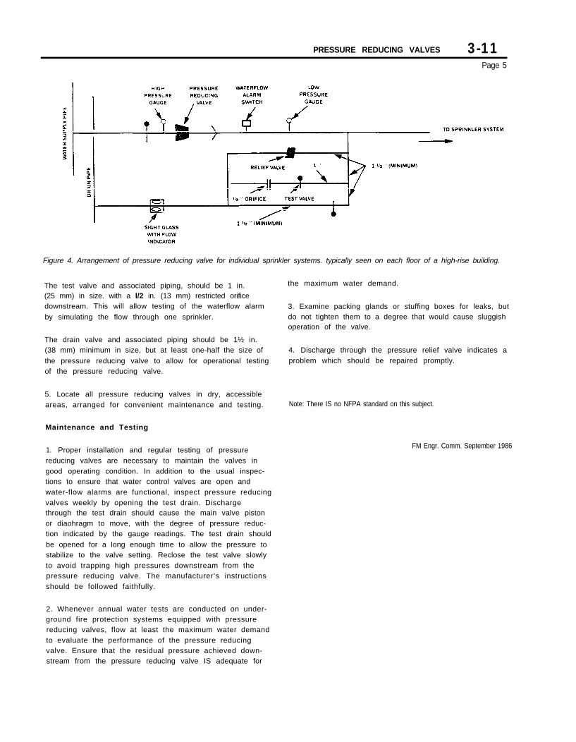
PRESSURE REDUCING VALVES 3-11Page 5
Figure 4. Arrangement of pressure reducing valve for individual sprinkler systems. typically seen on each floor of a high-rise building.
The test valve and associated piping, should be 1 in.(25 mm) in size. with a l/2 in. (13 mm) restricted orificedownstream. This will allow testing of the waterflow alarm
by simulating the flow through one sprinkler.
the maximum water demand.
3. Examine packing glands or stuffing boxes for leaks, butdo not tighten them to a degree that would cause sluggishoperation of the valve.
The drain valve and associated piping should be 1½ in.(38 mm) minimum in size, but at least one-half the size of
the pressure reducing valve to allow for operational testingof the pressure reducing valve.
4. Discharge through the pressure relief valve indicates aproblem which should be repaired promptly.
5. Locate all pressure reducing valves in dry, accessibleareas, arranged for convenient maintenance and testing. Note: There IS no NFPA standard on this subject.
Maintenance and Testing
1. Proper installation and regular testing of pressurereducing valves are necessary to maintain the valves ingood operating condition. In addition to the usual inspec-tions to ensure that water control valves are open andwater-flow alarms are functional, inspect pressure reducingvalves weekly by opening the test drain. Dischargethrough the test drain should cause the main valve pistonor diaohragm to move, with the degree of pressure reduc-tion indicated by the gauge readings. The test drain should
be opened for a long enough time to allow the pressure tostabilize to the valve setting. Reclose the test valve slowlyto avoid trapping high pressures downstream from thepressure reducing valve. The manufacturer’s instructionsshould be followed faithfully.
FM Engr. Comm. September 1986
2. Whenever annual water tests are conducted on under-ground fire protection systems equipped with pressurereducing valves, flow at least the maximum water demandto evaluate the performance of the pressure reducingvalve. Ensure that the residual pressure achieved down-stream from the pressure reduclng valve IS adequate for

Appendix E
Philadelphia Fire DepartmentPressure Regulating Device Fact Sheet
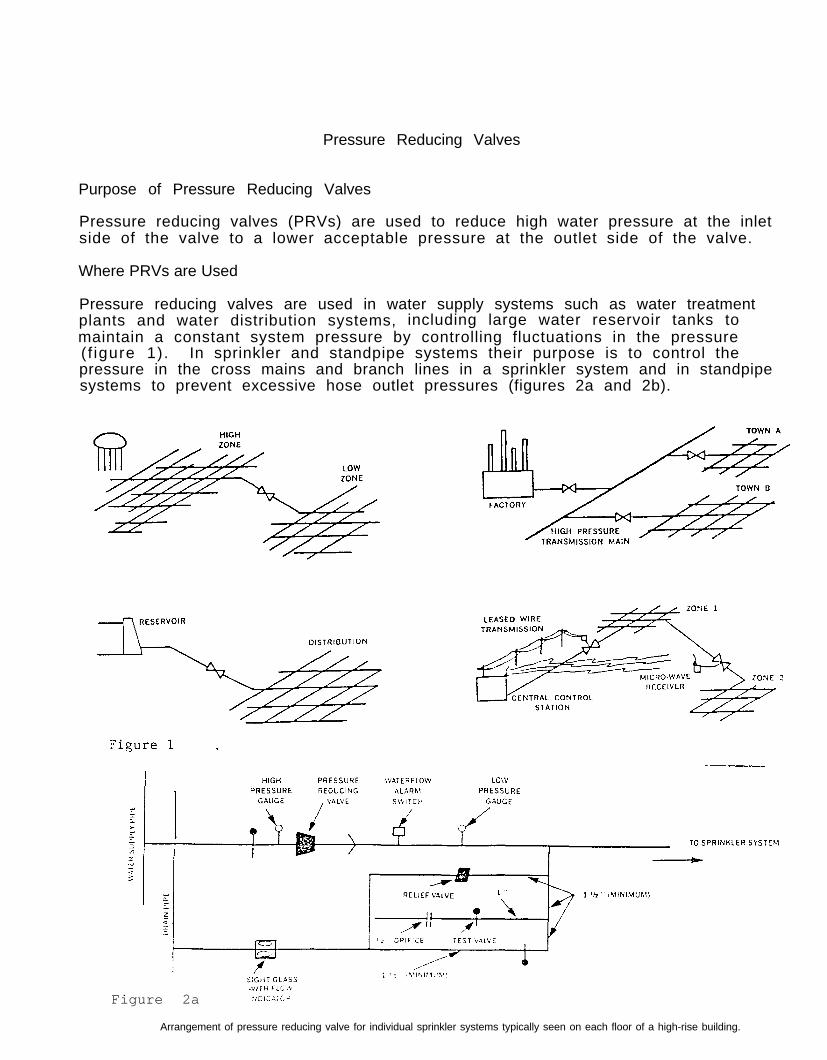
Pressure Reducing Valves
Purpose of Pressure Reducing Valves
Pressure reducing valves (PRVs) are used to reduce high water pressure at the inletside of the valve to a lower acceptable pressure at the outlet side of the valve.
Where PRVs are Used
Pressure reducing valves are used in water supply systems such as water treatmentplants and water distribution systems, including large water reservoir tanks tomaintain a constant system pressure by controlling fluctuations in the pressure(f igure 1). In sprinkler and standpipe systems their purpose is to control thepressure in the cross mains and branch lines in a sprinkler system and in standpipesystems to prevent excessive hose outlet pressures (figures 2a and 2b).
Figure 2a
Arrangement of pressure reducing valve for individual sprinkler systems typically seen on each floor of a high-rise building.
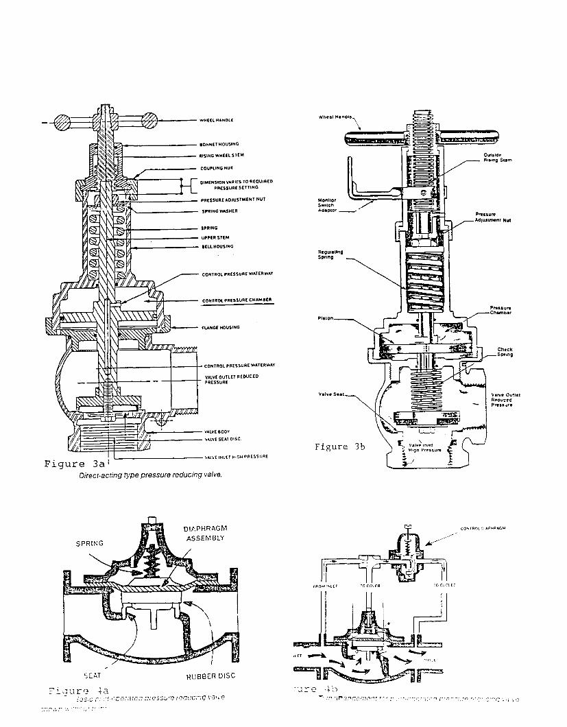

Types of PRVs Commonly Found on Standpipe Systems
The majority of PRVs installed in high-rise buildings in Philadelphia are thedirect-acting type. There are two varieties of these devices: pressure restrict-ing and pressure regulating.
Pressure Restricting Devices
Pressure restricting devices are simple devices or valves which control residualpressure by restricting the opening through which the water flows. They do notcontrol (reduce) static pressure.
Examples: Devices - fixed orifice disk or adjustable orifice valves withoutshut-off device.
Valves - adjustable valves with shut-off device.
Settings
Orifice disks - non-adjustable - ordered from manufacturer based on a spe-cific pressure and flow.
Orifice valves - adjustable orifice plate inside valve.
Adjustable valves - exterior adjustment scale controlling interior valveseat. The adjustment scale usually has a lock or seal toprevent tampering, but these can be overridden.
Pressure Regulating Valves
Pressure regulating valves control residual and static pressures by means of aninternal spring and pressure control chamber. The two parts, acting together, reg-ulate high inlet pressure to a lower, acceptable outlet pressure. Some valves alsoprovide a checking feature using an additional, light-weight spring to prevent anyback-flow or loss of water in the down stream portion of the system.
Settings
Most pressure regulating valves for standpipes are factory-set based on the cal-culated inlet pressure, desired outlet pressure, flow, and floor to beinstalled. They are ordered for a specific system and floor, with a labelattached to each valve indicating the floor of installation and the calculatedoutlet pressure at that floor. One brand is field adjustable and is set on siteby means of an adjusting rod.
Code Requirements for PRVs on Standpipe and Sprinkler Systems
NFPA
Standpipe Systems (NFPA 14-1990)
Where flows at a hose outlet exceed 100 psi, 3 pressure restricting or regulat-ing valve shall be installed.Where flows at a hose outlet exceedbe installed.
175 psi, a pressure regulating valve
-4-
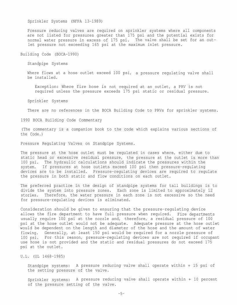
Sprinkler Systems (NFPA 13-1989)
Pressure reducing valves are required on sprinkler systems where all componentsare not listed for pressures greater than 175 psi and the potential exists fornormal water pressure in excess of 175 psi. The valve shall be set for an out-let pressure not exceeding 165 psi at the maximum inlet pressure.
Building Code (BOCA-1990)
Standpipe Systems
Where flows at a hose outlet exceed 100 psi, a pressure regulating valve shallbe installed.
Exception: Where fire hose is not required at an outlet, a PRV is notrequired unless the pressure exceeds 175 psi static or residual pressure.
Sprinkler Systems
There are no references in the BOCA Building Code to PRVs for sprinkler systems.
1990 BOCA Building Code Commentary
(The commentary is a companion book to the code which explains various sections ofthe Code.)
Pressure Regulating Valves on Standpipe Systems.
The pressure at the hose outlet must be regulated in cases where, either due tostatic head or excessive residual pressure, the pressure at the outlet is more than100 psi. The hydraulic calculations should indicate the pressures within thesystem. If pressures at hose outlets exceed 100 psi then pressure-regulatingdevices are to be installed. Pressure-regulating devices are required to regulatethe pressure in both static and flow conditions on each outlet.
The preferred practice in the design of standpipe systems for tall buildings is todivide the system into pressure zones. Each zone is limited to approximately 12stories. Therefore, the water pressure in each zone is not excessive so the needfor pressure-regulating devices is eliminated.
Consideration should be given to ensuring that the pressure-regulating deviceallows the fire department to have full pressure when required. Fire departmentsusually require 100 psi at the nozzle and, therefore, a residual pressure of 100psi at the hose outlet would not be adequate. Adequate pressure at the hose outletwould be dependent on the length and diameter of the hose and the amount of waterflowing. Generally, at least 150 psi would be required for a nozzle pressure of100 psi. For this reason, pressure-regulating devices are not required if occupantuse hose is not provided and the static and residual pressures do not exceed 175psi at the outlet.
U.L. (UL 1468-1985)
Standpipe systems: A pressure reducing valve shall operate within + 15 psi ofthe setting pressure of the valve.
Sprinkler systems: A pressure reducing valve shall operate within + 10 percentof the pressure setting of the valve.
-5-
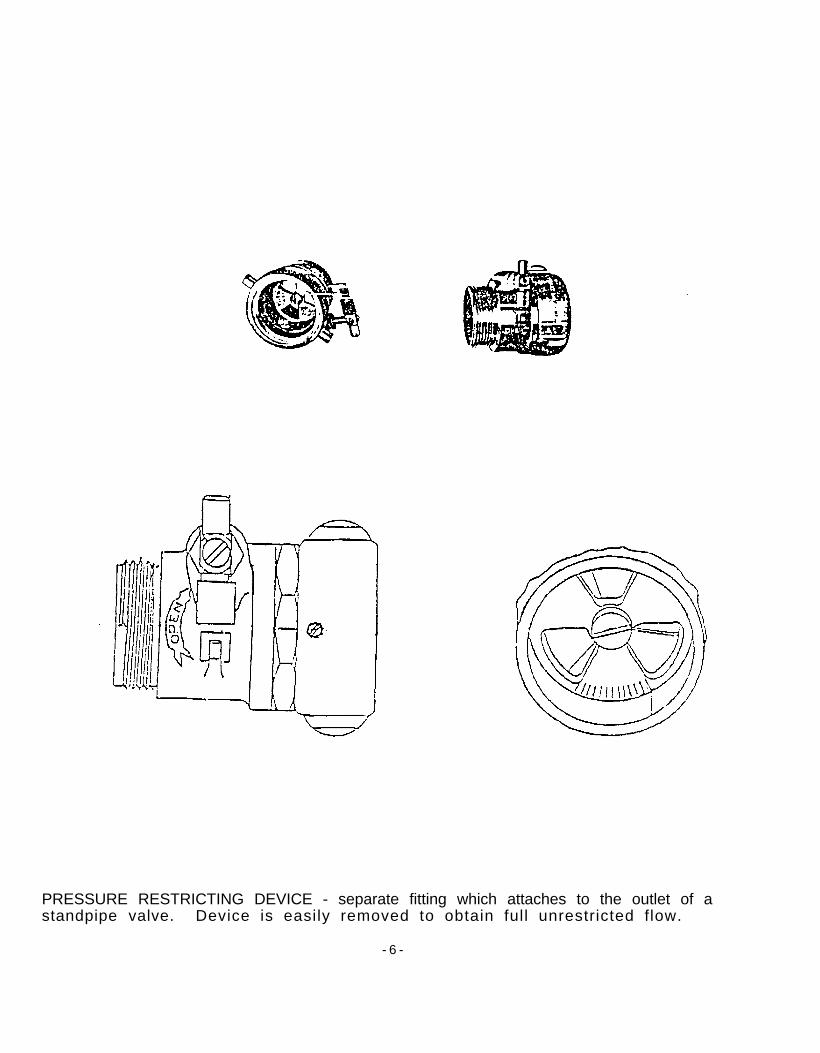
PRESSURE RESTRICTING DEVICE - separate fitting which attaches to the outlet of astandpipe valve. Device is easily removed to obtain full unrestricted flow.
- 6 -
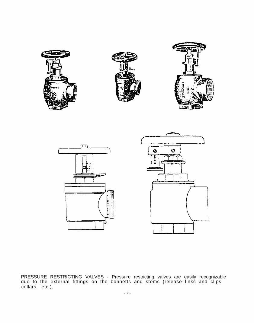
PRESSURE RESTRICTING VALVES - Pressure restricting valves are easily recognizabledue to the external fittings on the bonnetts and stems (release links and clips,collars, etc.).
- 7 -
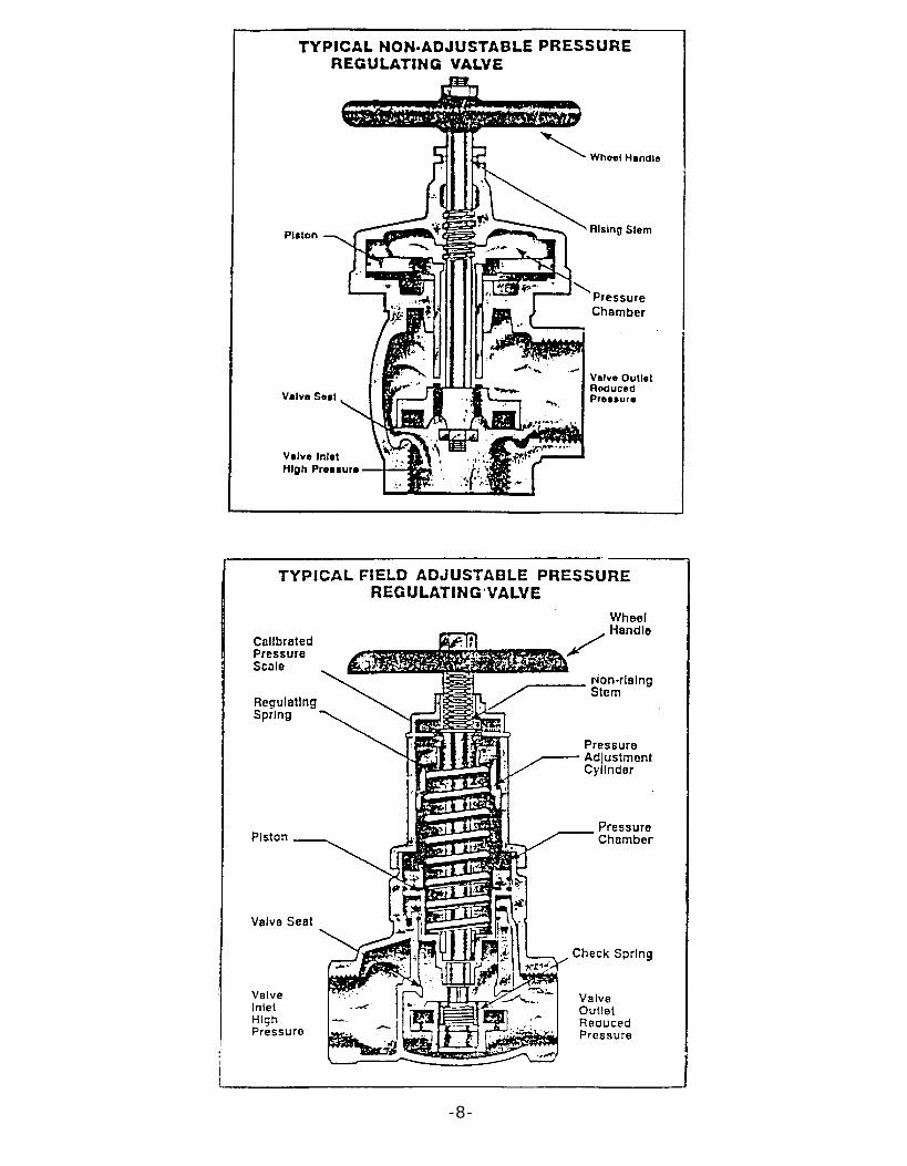
-8-
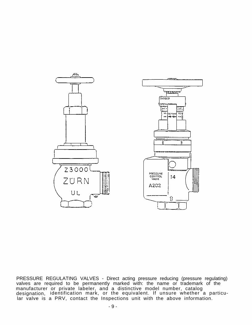
PRESSURE REGULATING VALVES - Direct acting pressure reducing (pressure regulating)valves are required to be permanently marked with: the name or trademark of themanufacturer or private labeler, and a distinctive model number, catalogdesignation, identif ication mark, or the equivalent. If unsure whether a particu-lar valve is a PRV, contact the Inspections unit with the above information.
- 9 -

Appendix F
PhiIadeIphia Fire Department Block Inspection Program
PHILADELPHIA FIRE DEPARTMENT
SUBJECT: BLOCK INSPECTION PROCEDURE
I. POLICY
OPERATIONALPROCEDURE 4AUGUST, 1990
Block inspection is an integral part of the Philadelphia FireDepartment's Fire Prevention program. The program provides uswith additional exposure in the community, enhancing publicrelations while discovering hazardous conditions that wouldcause a fire or present a life hazard. Professional appearance,courtesy and concern will have a lasting positive image ofPhiladelphia Fire Department members.
II. RESPONSIBILITY
It is the responsibility of each member to exercise the appro-priate control dictated by their rank in the implementation ofthis Operational Procedure.
III. DEFINITIONS
A. INSPECTIONS.
For the purpose of record keeping, inspections will berecorded as either regular or referral inspections.
1. Regular Inspections
Those inspections which reveal no violatlons orhazards, or minor violations or hazards which can becorrected immediately.
2. Referral Inspections
Those inspections which reveal serious violations ofthe Fire Code and/or fire, electrical or buildinghazards dangerous to life and property.
OPERATIONALPROCEDURE 4AUGUST, 1990
B. BUILDINGS UNDER CONSTRUCTION
1. Buildings under construction or renovation will betoured on a weekly basis by local companies. TheStation Manager will determine which day of the weekthe tour will be conducted. Centercompanies,
city firebecause of the large number of properties
under construction, will tour buildings being con-structed or renovated as frequently as is feasible.
2. The purpose of the tour of a building under construc-tion or renovation is to familiarize company memberswith the property. They should note fire protectionand exiting features, hazards or limitations due tothe construction, water supply and any fire or build-ing code violations.
3. The standpipe system should be inspected to ensure itis operational. Most fire protection systems are notrequired to be operational until a building is issueda Certificate of Occupancy (full building use) or aTemporary Certificate of Occupancy (selected flooruse). Standpipe systems are required to be opera-tional when construction reaches the fifth floor or65 feet in height (BOCA 10,13). From that time on,the system must be operational with a Fire Departmentintake connection and outlets on each floor up to andincluding the floor below the highest floor capableof being occupied (stairs and floors in place).
4. Fire and building code violations noted during thetour should be handled in the same manner as thosefound during block inspections.
IV. PROCEDURES
A. INSPECTION SCHEDULES
1. The Block Inspection Program will begin the secondMonday in January each year.
2. Block inspectionFriday,
will be performed Mondayexcluding holidays,
throughat the following times:
Division 1 - 0950 hours to 1150 hours and1250 hours to 1550 hours.
Division 2 - 1000 hours to 1200 hours andl300 hours to 1600 hours.
OPERATIONALPROCEDURE 4AUGUST, 1990
3. The FCC will announce weather conditions only, at0805 hours and 1205 hours. Block inspections willnot be performed when this report indicates tempera-tures below 400 F. or above 850 F.
4. Block checks will not be performed during extra alarmfires. Companies will return to their stations assoon as a second alarm is struck.
5. If, for any reason, a company is not going out onblock inspection as scheduled, they will notify theBattalion Chief. Upon request of the BattalionChief, the company will forward a memo to him.
B. COORDINATION
1. Deputy Chiefs will be responsible for the overallcoordination within their respective divisions.
2. Battalion Chiefs are responsible for the coordinationand quality of the Block Inspection Program withintheir battalions on their platoons.
3. Company officers will insure that all members undertheir command have a working knowledge of the BlockInspection Program, the Fire and Building Codes andrelated reports.
c. GUIDELINES
1. All buildings in the city will be inspected,annually, with the exception of one and twodwellings which will be inspected upon
familyrequest.
2. Each company's local area will be divided into foursections; one section assigned to each platoon.These sections will be rotated annually so that allplatoons inspect their entire district on a four yearbasis.
3. Inspectors will be arranged so that half of the com-panies in the battalion perform inspections inthe morning and the remainder in the afternoon.
OPERATIONALPROCEDURE 4AUGUST, 1990
4.
5.
Company inspection times will be alternated weekly,that is, in the. morning one week, in the afternoonthe next.
Inspections will normally be performed by the entirecompany, including the officer, working in teams oftwo or three. Example: Quota 1 and 3, inspectionteam will be officer and two firefighters, driverstays with the apparatus. If the quota is 1 and 4,inspection team will be officer and 1 firefighter;and the second team will be two firefighters, driverstays with the apparatus. In those areas where appa-ratus parking is a problem or the size of a buildingmakes it impossible for inspecting members inside thebuilding to hear the siren, the Battalion Chief willhave those companies send individual members out toperform inspections. This will be coordinatedthrough the Deputy Chief. When additional membersare detailed to a company for this purpose, theassigned members, rather than the detailed members,will perform the inspections.
6. The Battalion Chief will order and maintain a suffi-cient supply of Fire Prevention Check Forms for thebattalion. Companies needing forms will request themfrom their Battalion Chief.
D. BLOK INSPECTION DUTIES
1. A Fire Prevention Check Form will be prepared foreach building inspected. Where required, the VitalBuilding Information and Emergency Guide to HazardousMaterials Storage Forms will be prepared and/orupdated. This information will be reviewed, as partof the station exercise, by all platoons to familiar-ize themselves with existing hazards and conditionsin their local district.
2. Unsafe conditions, such as defective traffic signals,missing directional signs, missing sewer inletcovers, missing hydrant caps,. potholes, etc., will bereported. Notify the FCC via the fire radio if aserious hazard exists, other conditions will bereported on a Complaint Report by City Employee Formupon return to station.
OPERATIONALPROCEDURE 4AUGUST, 1990
3.
4.
5.
6.
Companies encountering buildings without a visiblestreet address will notify the owner that it is intheir best interest to clearly identify all buildingsto ensure that emergency services are not delayed.
Block inspections provide an excellent opportunityfor driver training. Company officers will takeadvantage of the time spent on the street to trainnew drivers and provide refresher training for quali-fied drivers. It also enables company personnel tobecome familiar with their local district.
Companies will remain attentive to new constructionwithin their local district and immediately informFire Survey of same. If possible, they will securethe information in regard to the numbering systembeing used and pass this information on to FireSurvey.
School properties will be inspected to ascertainthat apparatus accessibility to the exterior portionsof the school is insured. Where appropriate entranceto school yards is required for rescue and firefighting purposes and is not provided, via asufficiently wide entrance gate, a removable sectionof fencing must be maintained. This removable sectionwill be provided with a center post painted red 'foreasy identification. Inspecting members will ascer-tain that the required entrance to the school yardsis not blocked and that appropriate "No Parking"signs are posted. In those cases where access tothe school yard is not available, a duplicate memo-randum will be forwarded to the Deputy Chief, FirePrevention Division.
RADIO COMMUNICATIONS
When leaving the station, the FCC will be notifiedvia fire radio, that the company is going on blockinspection. When inspections are performed by indi-viduals and the apparatus is not t&en, the FCC willbe notified, via fire phone, when leaving and return-ing to station.
OPERATIONALPROCEDURE 4AUGUST, 1990
2.
3.
4.
Upon arriving on location, where block inspectionswill be performed, the FCC will be notified. When-ever the apparatus is moved to a new location, theFCC will again be notified. This will serve tolocate "dead" spots with regard to the fire radioand, additionally, inform other companies of yourlocation.
While a company is inspecting, the apparatus driverwill remain with the apparatus to receive fire radiomessages. If the company receives a run or isinstructed to return to their station for any reason,the member at the apparatus will sound the siren torecall the other members. Members performing inspec-tions will ensure that they are not too distant fromthe apparatus to hear the siren.
On those apparatus where it is possible, the fireradio will be turned to the standby position and theengine shut off. This will conserve fuel and stillenable the member remaining at the apparatus tomonitor radio messages. If a radio transmission isrequired, the motor will be started before transmis-sions are made.
5. Companies responding to an alarm while on blockinspection will, upon completion of their assignment:
a. If a fire report is required, return 'to station,and complete same, and then resume blockinspections. If Only an Analysis of Fire AlarmResort is required, company will prepare theform after block inspections are completed forthe day.
b. If no fire report is required, notify Fire Dis-patcher that the company is resuming blockinspecti on (give location).
Companies dispatched to alarms during the hours ofblock inspections will use extra caution whenresponding, as companies on inspections may not beusing their normal response routes.
OPERATIONALPROCEDURE 4AUGUST, 1990
F. REPORTS AND RECORDS
1. Policies and Procedures
A folder will be maintained containing statements ofDepartment, battalion or company policies and proce-dures concerning block inspections.
2. Block Check Folders
A folder will be prepared for each block shown on thecompany local district map. A drawing will be madeon the front of each folder showing all streets con-tained in that block. Folders will be maintained innumerical order. Fire Prevention Check Forms(#76-24) will be retained, for each property, in theappropriate folder.
3. Referral Reports
An "Action Pending" folder will be established forretention of Fire Inspection Referral Reports(#76-40) which have been forwarded by the company andon which no reply has been received from the Depart-ment of Licenses and Inspections via the FireMarshal's Office.
All fire inspection referral forms returned to thecompany, from the Department of Licenses andInspections, will be permanently retained in theappropriate block check folders.
4. Board of Safety and Fire Prevention Reports
After a request for variance from the Fire Code isruled on, a copy of the ruling will be sent throughchannels to the first-in engine company. This copyof the variance ruling will be attached to the insidecover of the block folder and retained permanentlyand referred to when inspecting the property eachyear. The date of the variance will be noted in theleft hand margin.
5. Progress Reports
Companies will record the number of regular antireferral inspections performed each day on the officedesk calendar.
OPERATIONALPROCEDURE 4AUGUST, 1990
If no inspections are performed that day, the reasonwill be noted. . This information will be transferredto the Company Block Check Progress Report and for-warded to the Battalion Chief on Saturday morning.The Battalion Chief will consolidate the figures onthe Battalion Block Check Progress Report. BattalionChiefs will also call these figures into the DeputyChief of their division on Sunday night. When acompany/platoon has completedtions, memorandum stating this will be
their block inspec-
forwardeda through' channels,Fire Prevention Division.
to the Deputy Chief,The Fire Prevention Divi-
sion will maintain a record of completions.
V. FORMS REQUIRED
A. FORMS
Consult the Forms Directive for preparation of all forms.
1. Battalion Block Check Progress Report, #76-105.
2. Company Block Check progress Report, #76-104.
3. Complaint Report by City Employee, #70-35.
4. Emergency Guide to Hazardous Materials Storage,#76-112.
5. Fire Inspection Referral, $76-40.
6. Fire Prevention Check, #76-24.
7. Vital Building Information #76-80.
BY ORDER OF THE FIRE COMMISSIONER
Appendix G
Philadelphia Fire Code AmendmentsAdopted after the One Meridian Plaza Fire
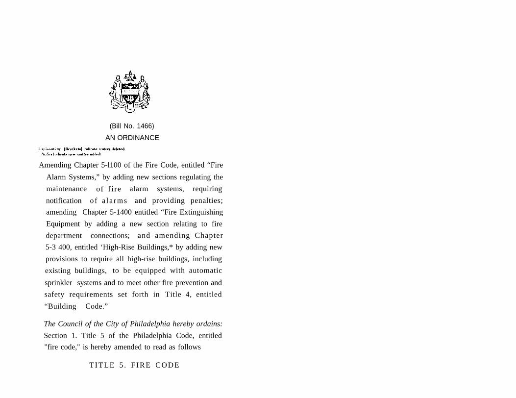
(Bill No. 1466)
AN ORDINANCE
Amending Chapter 5-l100 of the Fire Code, entitled “Fire
Alarm Systems,” by adding new sections regulating the
maintenance of f i re alarm systems, requiring
notification of a la rms and providing penalties;
amending Chapter 5-1400 entitled “Fire Extinguishing
Equipment by adding a new section relating to fire
department connections; and amending Chapter
5-3 400, entitled ‘High-Rise Buildings,* by adding new
provisions to require all high-rise buildings, including
existing buildings, to be equipped with automatic
sprinkler systems and to meet other fire prevention and
safety requirements set forth in Title 4, entitled
“Building Code.”
The Council of the City of Philadelphia hereby ordains:
Section 1. Title 5 of the Philadelphia Code, entitled
"fire code," is hereby amended to read as follows
TITLE 5 . F IRE CODE
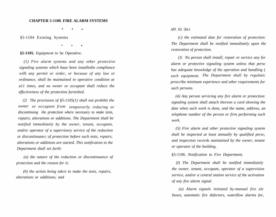
CHAPTER 5-1100. FIRE ALARM SYSTEMS
§5-1104 Existing Systems
§5-1105. Equipmcnt to be Operative.
(1) Fire alarm systems and any other protective
signaling systems which haue been installedin compliance
wilh any permit or order, or because of any law or
ordinance, shall be maintained in operative condition at
a11 times, and no owner or occupant shall reduce the
effectiveness of the protection furnished.
(2) The provisions of §5-1105(1) shall not prohibit the
owner or occupant from temporarily reducing ordiscontinuing the protection where necessary to make tests,
repairs, alterations or additions. The Department shall be
notified immediately by the owner, tenant, occupant,
and/or operator of a supervisory service of the reduction
or discontinuancc of protection before such tests, repairs,
alterations or additions are started. This notification to the
Department shall set forth:
(a) the nature of the reduction or discontinuance of
protection and the reason for it;
(b) the action being takcn to make the tests, repairs,
alterations or additions; and
APP. NO. 594-3
(c) the estimated date for restoration of protection:
The Department shall be notified immediately upon the
restoration of protection.
(3) No person shall install, repair or service any for
alarm or protective signaling system unless that persc
has adequate knowledge of the operation and handling (
such equipment. The Department shall by regulatic
prescribe minimum experience and other requirements for
such persons.
(4) Any person servicing any fire alarm or protection:
signaling system shall attach thereon a card showing the
date when such work is done, and the name, address, an
telephone number of the person or firm performing such
work.
(5) Fire alarm and other protective signaling system
shall be inspected at least annually by qualified persc,
and inspection records maintained by the owner, tenant
or operator of the building.
§5-1106. Notification to Fire Department.
(I) The Department shall be notified immediately
the owner, tenant, occupant, operator of a supervision
service, and/or a central station service of the activation
of any fire alarm signal.
(a) Alarm signals initiated by-manual fire alc
boxes, automatic fire defectors, waterflow alarms for,
APP. NO. 594-4
automatic sprinkler systems or activation of other fire
suppression systems or equipment shall be treated as fire
alarms.
(b) Central station services shall immediately
retransmit alarm signals received from protected
properties to the Department.
[§5-1105]§5-1107. Penalties.
(2) In addition to any other penalties provided in this
Title any person who violates §5-1106(l), or the regulations
issued thereunder, shall be subject to a fine of three
hundred ($300.00) dollars for each violation or to
imprisonment not exceeding ninety (90) days, or both.
(3) in addition to any other procedures, remedies or”
penalties provided by this ‘Title, the provisions of’
$5-1106(l) may be enforced in the manner set forth in this
section.
(a) Notice of violation.
(1) Whenever an investigation by the Department of
licenses and Inspections or the Department discloses any
violation of the provisions of §5.l106(1), the violator shall
be issued a printed notice of violation by the person
conducting the inspection. Such notice shall bear the date,
time and nature of the violation, identity and address of
the violator, the amount to be remitted in response to the
APP. NO. 594-5
notice of violatian, and the penalty which can be imposed
by the court for the violation. The notice shall be signed by
the person issuing the notice and shall bear the official
identification number of the person issuing the violation
notice. For each. violation, a separate notice of violation
may be issued under this section.
(.2) Any person who receives a notice of violation,
may within ten (10) days, pay theamount of three hundred
($300.00) dollars, admit the violation and waive
appearance before a Municipal Court Judge. The notice of
violation shall contain an appropriate statement for
signature by the violator for the purpose of admitting the
violation when he or she remits the stipulated payment.
Any paymemt made under this subsection shall not relieve
the violator of the responsibility for correcting the violation
set forth in the notice of violation.
(.3) If a person who receives a notice of violation fails
to pay the prescribed payment within ten (10) days of the
issuance of the notice of violation, a code enforcement
compliant shall be issued for the violation in such a
manner provided by law. If the person named in the code
enforcement complaint is found to have violated
§5-1106(1), he or she shall be subject to the penalties set
forth in §5-1107(2).
(.4) Any fine or costs imposed by the courts shall be
entered as a judgment against the violator. Any fine and
A P P . N O . 5 9 4 - 7APP. NO. 594-6
costs imposed by the court shall be paid within ten (10)
days of its imposition. If the fine together with any court
cost is not paid within such period, the violator shall be
subject to proceedings for contempt of court and/or
collection of the fine as provided by law.
(4) In addition to any other sanction or remedial
procedure provided in this Title, any person who shall
violate the provisions of §5-1106(1) or the regulations
pursuant thereto, shall be subject to referral to the Office
of the District Attorney.
CHAPTER 5-1400. FIRE EXTINGUISHING
EQUIPMENT
§5-1403. Equ ipment to be Operative.
(1) Sprinkler systems, standpipe systems, [alarm
systems,] and any -other [protective or] extinguishing
systems which have been installed in compliance with any
permit or order, or because of any law or ordinance, shall
be maintained in operative conditions at all times, and no
owner or occupant shall reduce the effectiveness of the
protection furnished.
§5-1405. Fire Department Connections on Sprinkler
and Standpipe Systems.
(1) All fire department intake connections to sprinkler
and standpipe systems shall have two (2) or more two an
one -half inch female National Hose (NH) standard threa
intake fittings. If an intake connection feeds one (I) zon
rather than the entire building, the floors encompassed .
the zone shall be indicated ‘at the intake which feeds 11
zone..
Exception: Dry standpipe systems with six inch
riser piping shall have connections with three
two and one-half inch female NH standard
thread intake fittings.
(2) Standpipe outlets on Class I and Class III system
that is, those designed for fire department use, shall have
floor outlets with two and one-half inch male NH standard
thread fittings.
CHAPTER 5-3400. HIGH-RISE BUILDINGS.
§5-3402. Aplication.
(1) [New high-rise buildings shall conform to Sect.
629-0 “High-Rise Buildings” of the Basic Building
Code/1981 published by the Building Officials and Code
Administrators (BOCA) International, Inc. and to
applicable provisions of this Chapter.]
APP. NO. 594-9
NO. 594-8
Existing -high-rise buildings shall conform to
602.3 ‘Sprinkler system’ of the Building Officials
Code Administrators (BOCA) National Building
Eleventh Edition, 1990, as incorporated by Title 4 of
Philadelphia Code, entitled -Building Code,’ and to
provisions of this Chapter.
Exception: In R-2 occupancies, as defined in the
Building Code sprinklers are only required in
areas as specified by Section 5-3405 of this Code
provided that:
(1) Smoke detectors connected to the building’s
electric system are provided in each dwelling unit
and installed in accordance with Section 1018 of
the Building Code within two (2) years of the date
of this chapter.
Exception: Electrical interconnection of
smoke detectors within a dwelling unit is
not required, provided that the alarm level
of each detector is 15 decibels above the
ambient noise level in every occupied space
within the unit.
(2) Doors from dwelling units opening into a
common corridor are self-closing within one (1)
year of the effective date of this chapter.
within one (1) year of the effective date of this Chapter the
of every existing high-rise building shall submit to
the Department of Licenses and Inspections for approval a
detailed written description of the methods and schedule
to be used for compliance with this Chapter. In no case
shall the plan provide for the completion of all work
required by this section later than eight (8) years from the
effective date of this Chapter. Applications for permits
necessary for compliance with the provisions of this
Chapter shall be submitted to the Department of Licenses
and Inspections upon approval of the written description
in accordance with the following schedule:
(1) Within eighteen (18) months, water supplies to all
floors of the building, and compliance with the sprinkler
and standpipe connection requirements in §5-1405;
(2) Within thirty (3O) months, fire suppression
systems in twenty percent (20%) of the floors of the
building;
(3) Within thirty-nine (39) months, fire suppression
systems in forty percent (40%) of the floors of the building;
(4) Within forty-eight (48) months, fire suppression
systems in sixty percent (60%) of the floors of the building;
(5) Within fifty-seven (57) months, fire suppression
systems in eighty percent (80%) of the floors of the
building; and

APP. NO. 594-11
N 0 . 5 9 . 1 . 1 0
(6) Within sixty-six (66) months, fire suppression
as in one hundred percent (100%) of the floors of the
bu i l d ing .
to the expirat ion of one (1) year af ter the ef fect ive
o f t h i s C h a p t e r . ] U p o n n o t i f i c a t i o n b y t h e
department of Licenses and Inspections that each permit
f ew i s comple t e , t he app l i can t sha l l ob ta in permi t s
t h i r t y ( 30 ) days [o f no t i f i ca t i on] .
3105. Fire Suppression Systems.
A l l e x i s t i ng h igh - r i s e bu i ld ings where s tandp ipe
1.5 exceed two hundred seventy-five (275) feet from the
at fire department connection to the roof or highest
act ion shal l be equipped with wet s tandpipe systems
called in accordance with NFPA 14 and the BuildingExplanation(Bracked) indicate matter deletedItalics indicate new matter added
Applications for permits necessary for compliance
the provisions of this section shall be shall be submitted to the
deparment of Licenses and Inspections within three (3)
of the effective date of this chapter.
109. Testing of Electrical Systems.
Inspections. Tests shall include 11 transfer from normal to
standby and/or emergency power under full load operating
c o n d i t i o n s . T e s t s s h a l l b e p e r f o r m e d b y a l i c e n s e d
electrician who shall certify to the Department of Licenses
and In spec t i ons t ha t t he s y s t em i s i n p roper work ing
order. Any fai lures shal l also be reported and shal l be
repaired and the system retested within thirty (30) days.
§5-3410. Notification of Fire Department.
The Department shal l be not i f ied immediately of any
changes to the f ire suppression, f ire alarm, emergency
e l ec t r i ca l , and any o ther bu i ld ing s y s t ems wh ich a re
necessary during fire department operations in a building.
Detai led information and instruct ions on al l equipment
as soc ia t ed w i th t he se s y s t ems sha l l be p rov ided to t he
Department .
SECTION 2 . Th i s Ord inance sha l l t ake e f fec t imme-
d i a t e l y
A standby and/or emergency electrical systems shall
be tested at least annually in accordance with the
action of the Department of Licenses and
APP. NO. 594-12
CERTIFICATION: This is a true and correct copy of theoriginal Ordinance approved by the Mayor on
DECEMBER l8,1991
Deputy Chief Clerk of the Council

Appendix H
Photographs
Numerous slides and photographs are included with the masterreport at the United States Fire Administration. The photographspresented on the following pages were taken by Charles Jenningsafter the fire, except where otherwise noted.
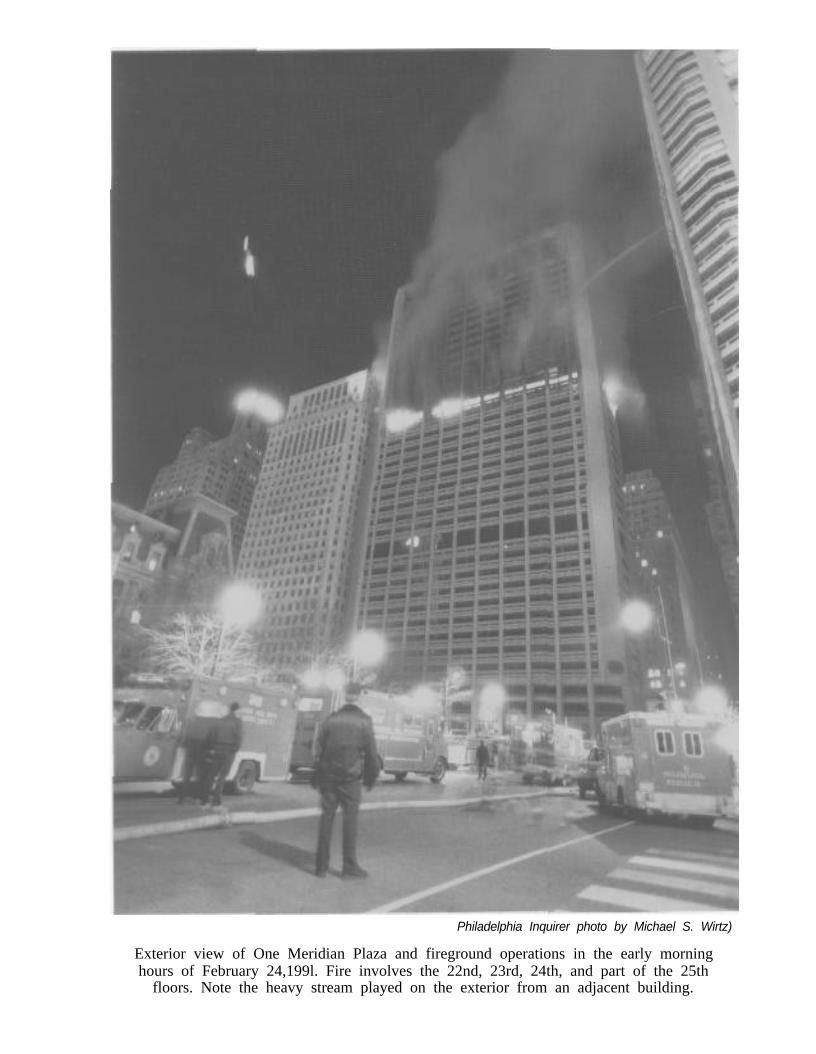
Philadelphia Inquirer photo by Michael S. Wirtz)
Exterior view of One Meridian Plaza and fireground operations in the early morninghours of February 24,199l. Fire involves the 22nd, 23rd, 24th, and part of the 25th
floors. Note the heavy stream played on the exterior from an adjacent building.
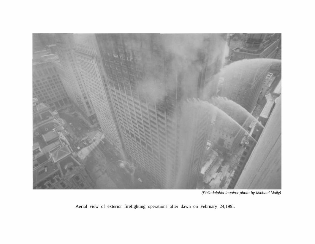
(Philadelphia Inquirer photo by Michael Mally)
Aerial view of exterior firefighting operations after dawn on February 24,199l.
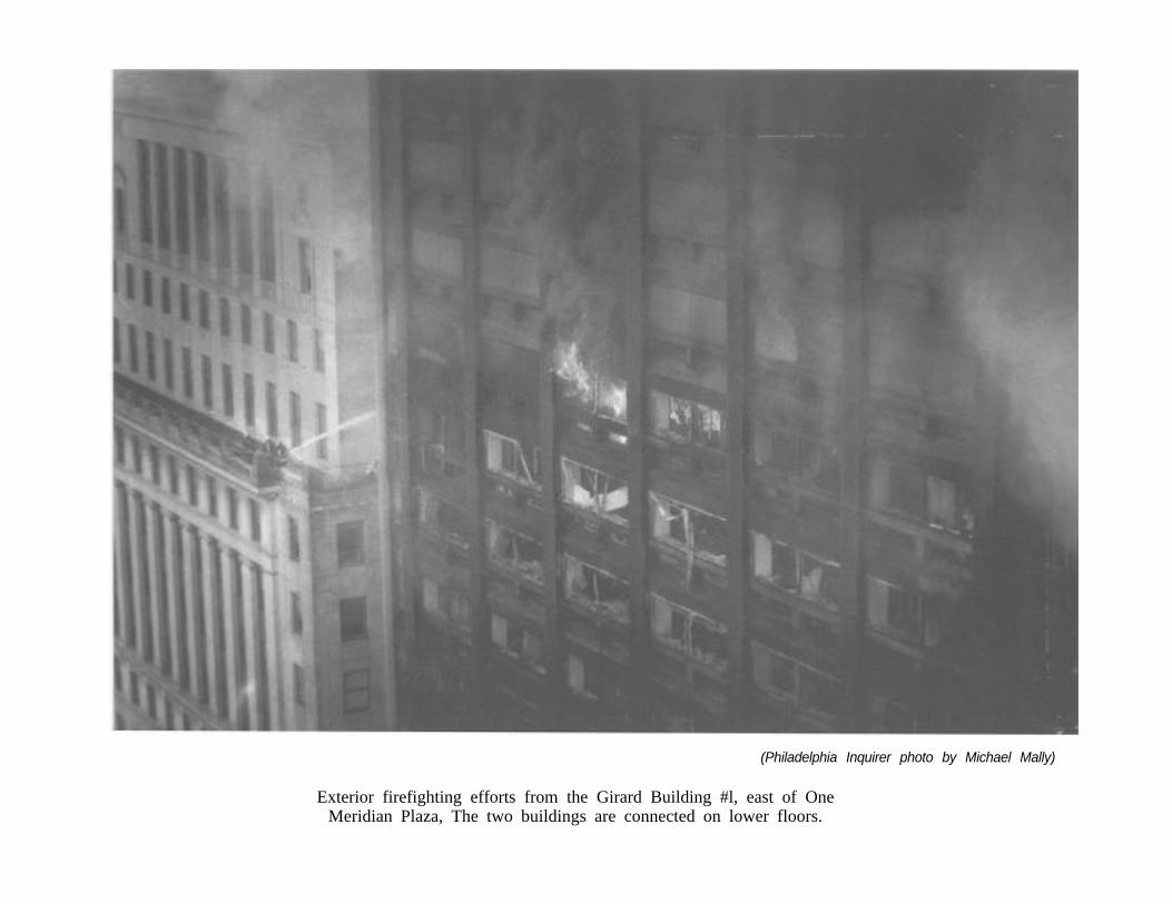
(Philadelphia Inquirer photo by Michael Mally)
Exterior firefighting efforts from the Girard Building #l, east of OneMeridian Plaza, The two buildings are connected on lower floors.
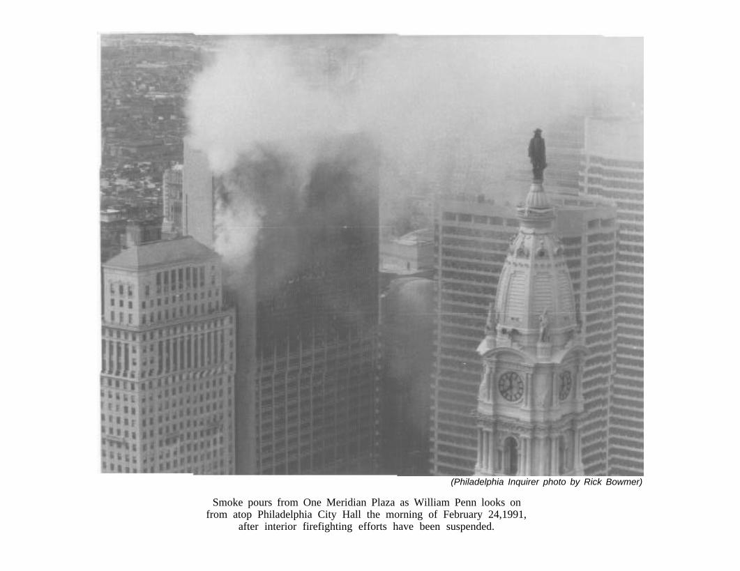
(Philadelphia Inquirer photo by Rick Bowmer)
Smoke pours from One Meridian Plaza as William Penn looks onfrom atop Philadelphia City Hall the morning of February 24,1991,
after interior firefighting efforts have been suspended.
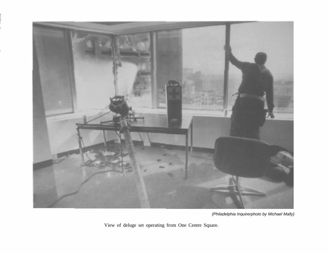
(Philadelphia Inquirerphoto by Michael Mally)
View of deluge set operating from One Centre Square.
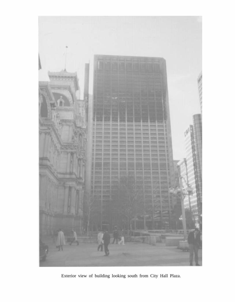
Exterior view of building looking south from City Hall Plaza.
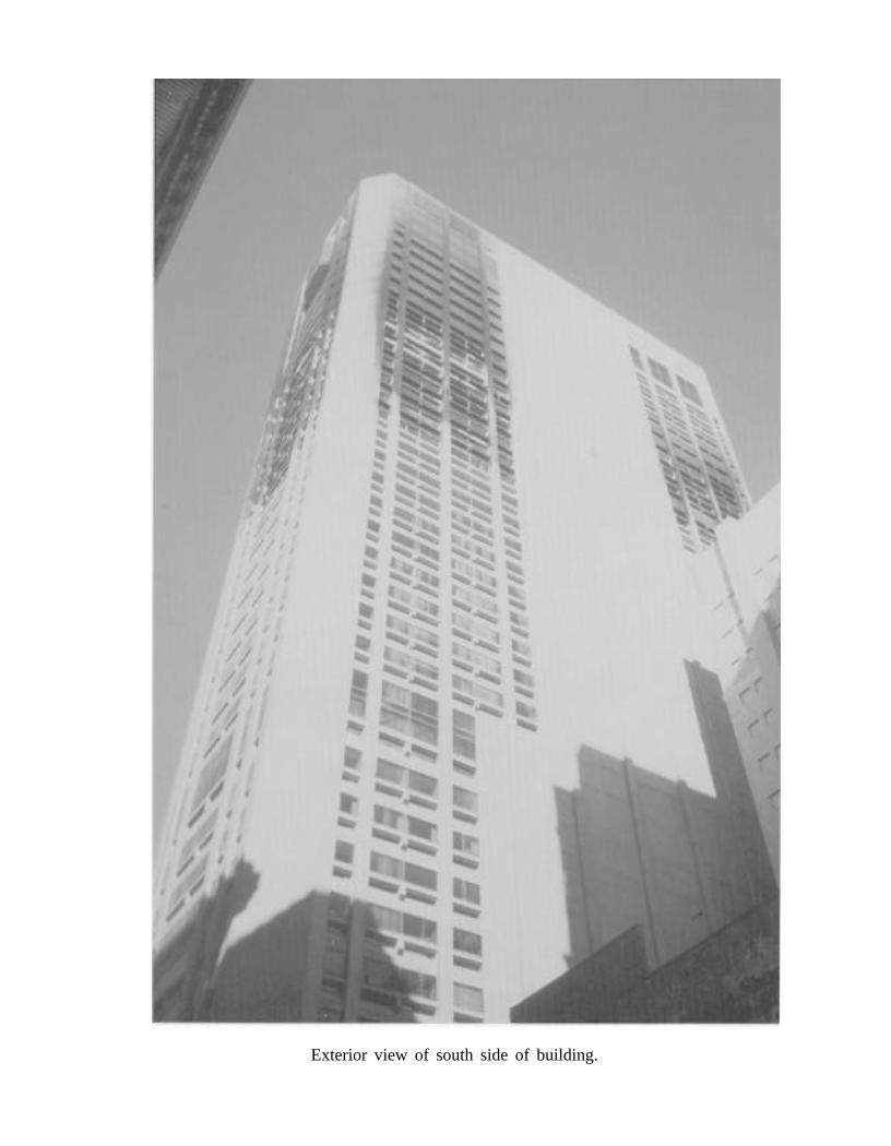
Exterior view of south side of building.
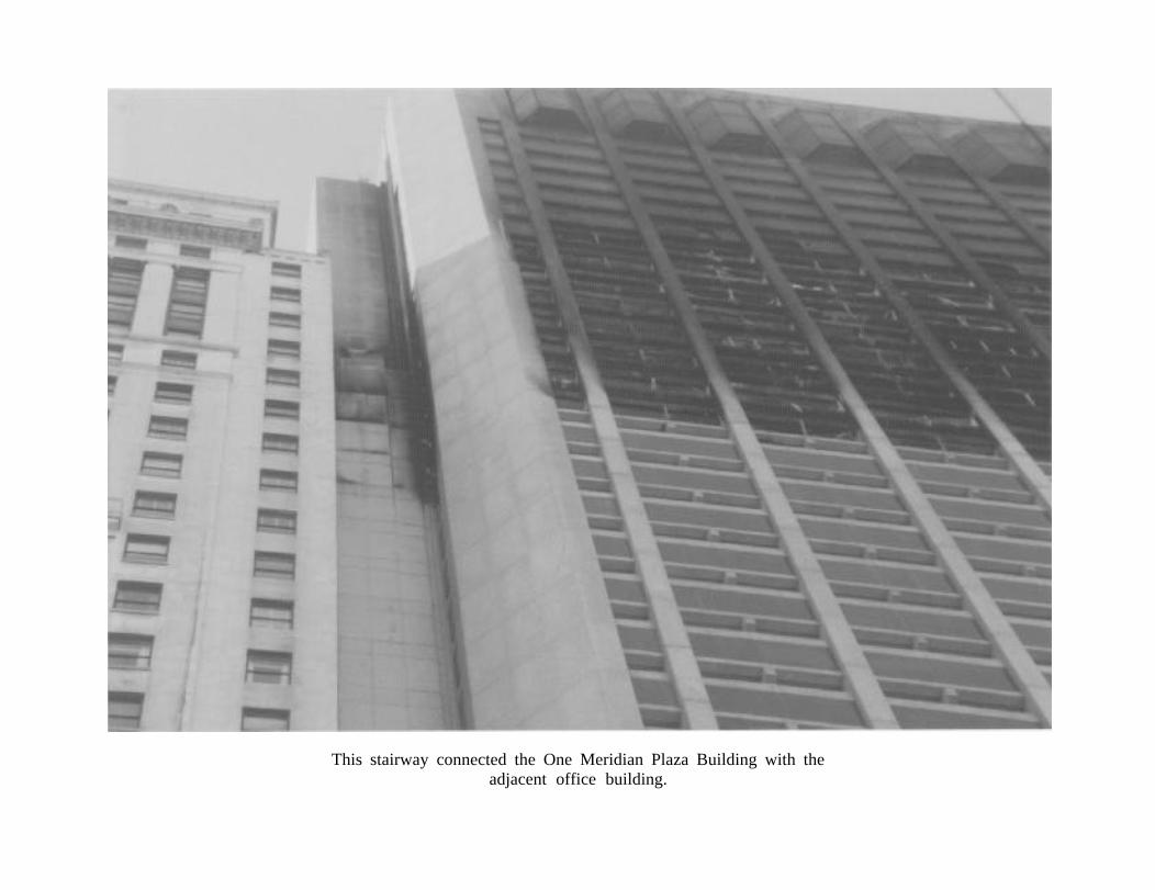
This stairway connected the One Meridian Plaza Building with theadjacent office building.
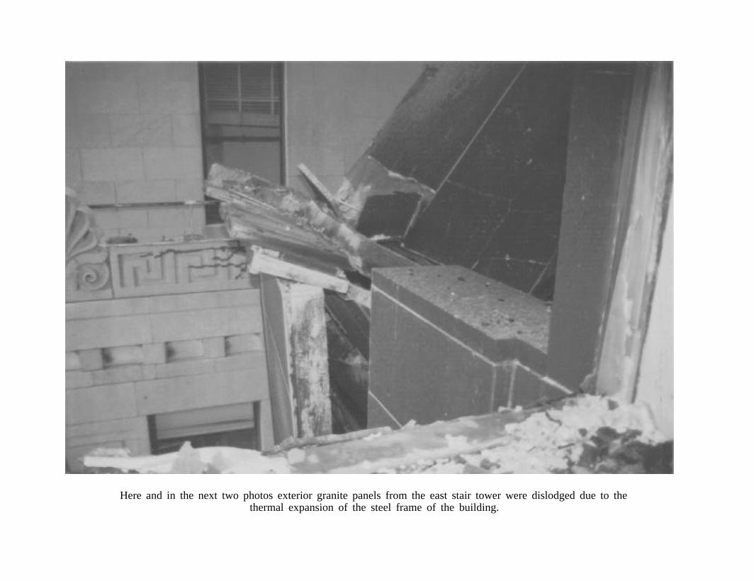
Here and in the next two photos exterior granite panels from the east stair tower were dislodged due to thethermal expansion of the steel frame of the building.
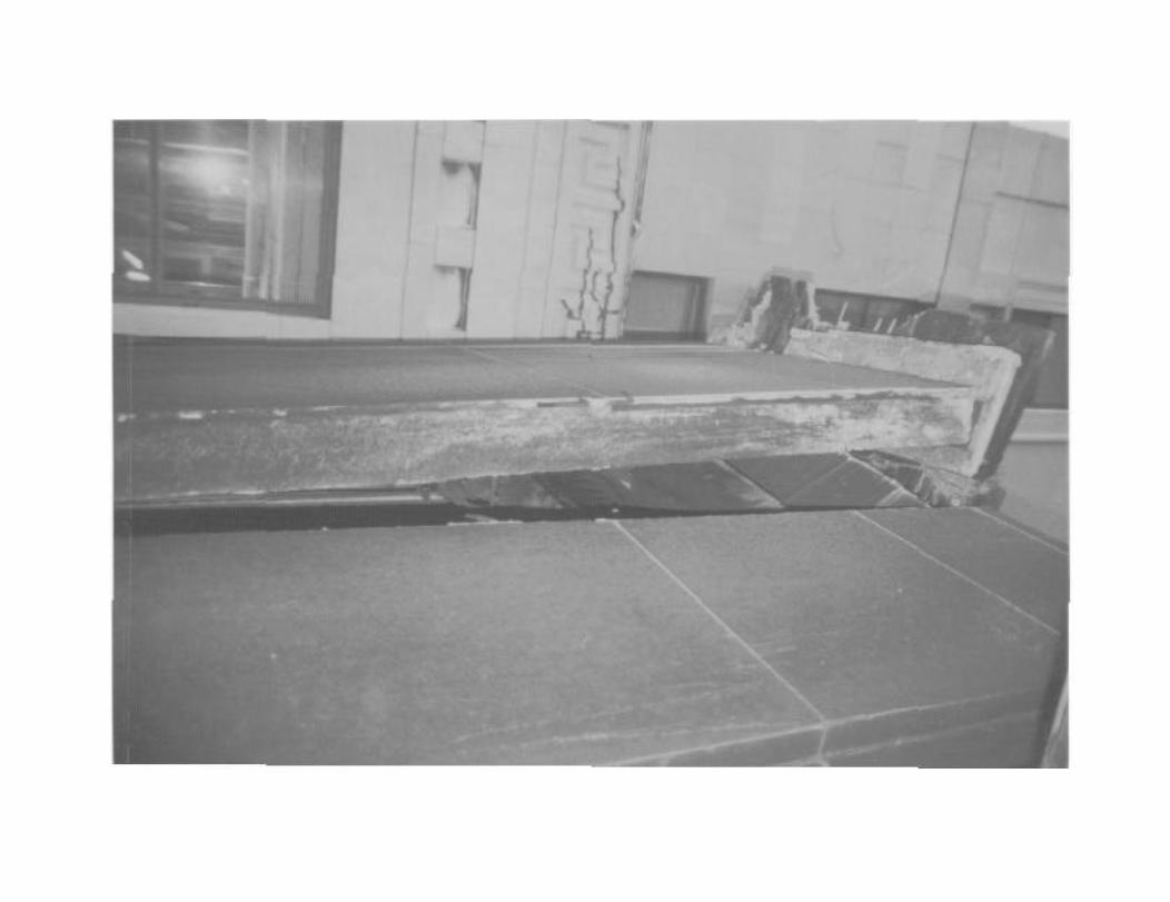
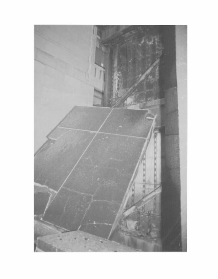

Photo by James David
One of the areas of fire penetration on the 30th floor where a single sprinkler head activatedto stop the upward extension of the fire.
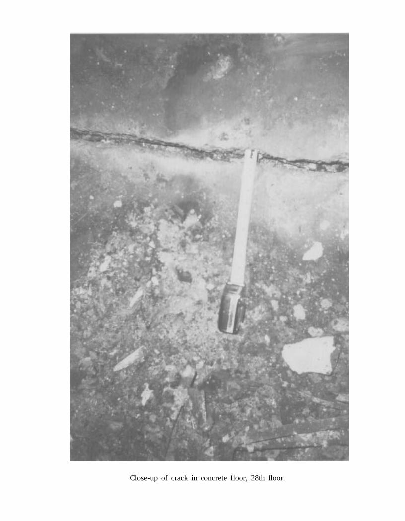
Close-up of crack in concrete floor, 28th floor.
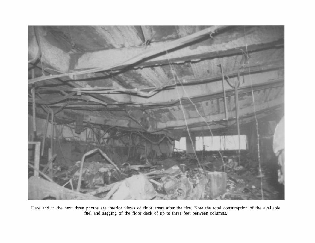
Here and in the next three photos are interior views of floor areas after the fire. Note the total consumption of the availablefuel and sagging of the floor deck of up to three feet between columns.
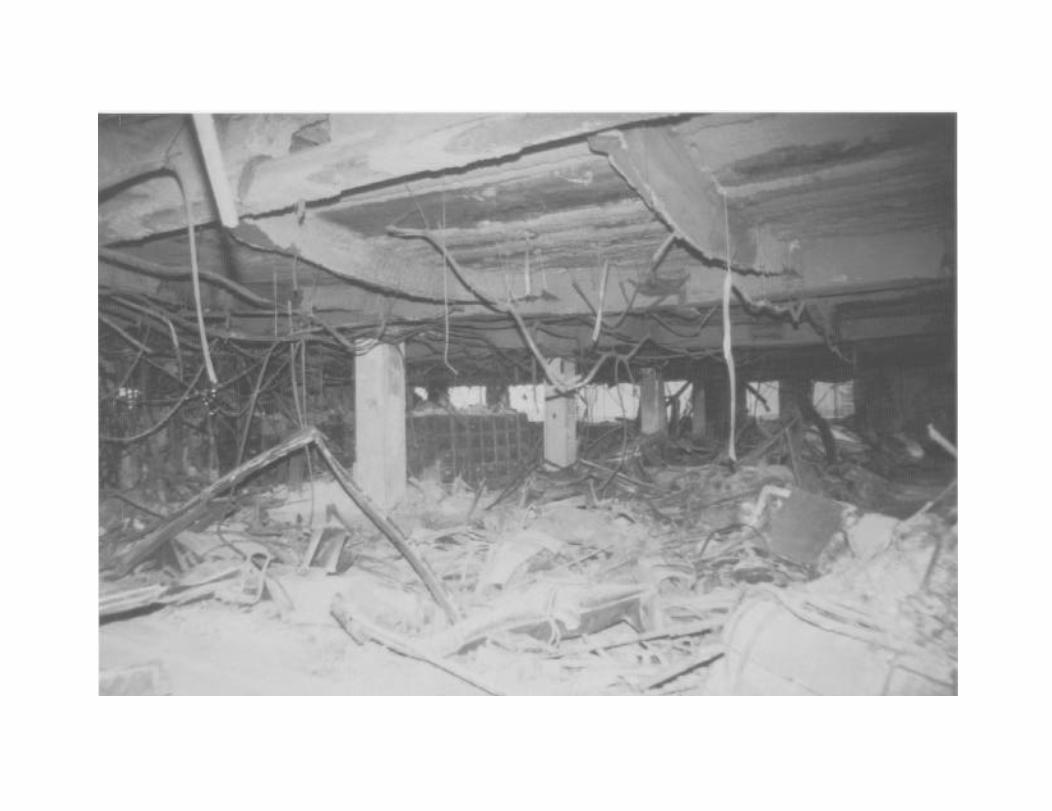
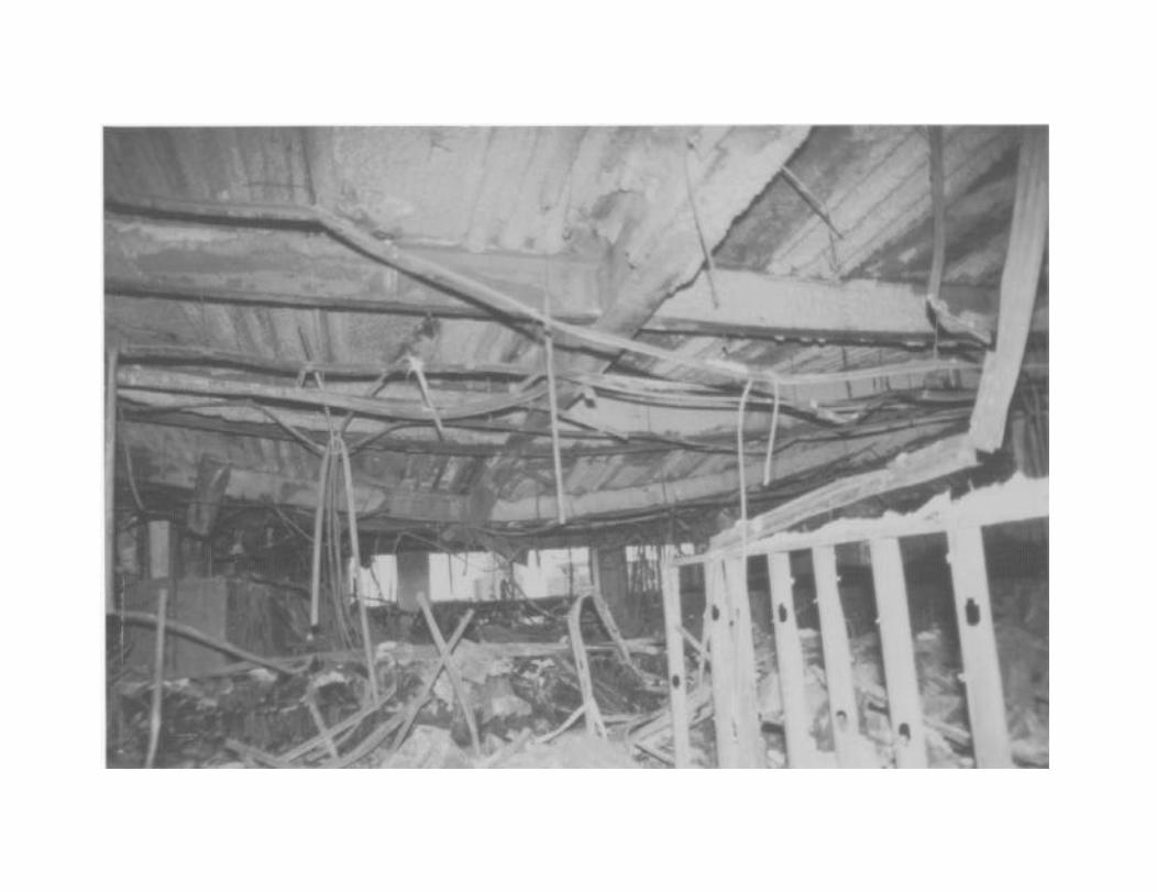
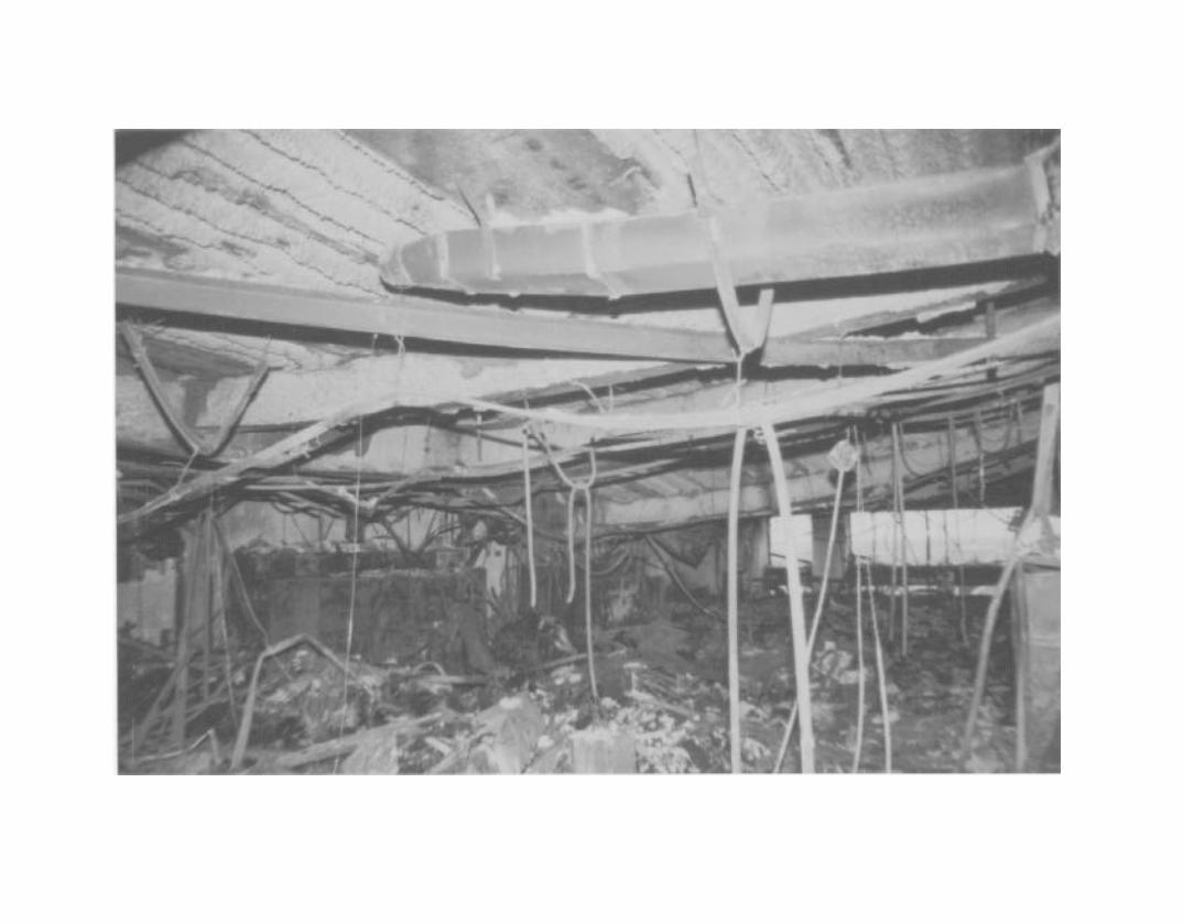
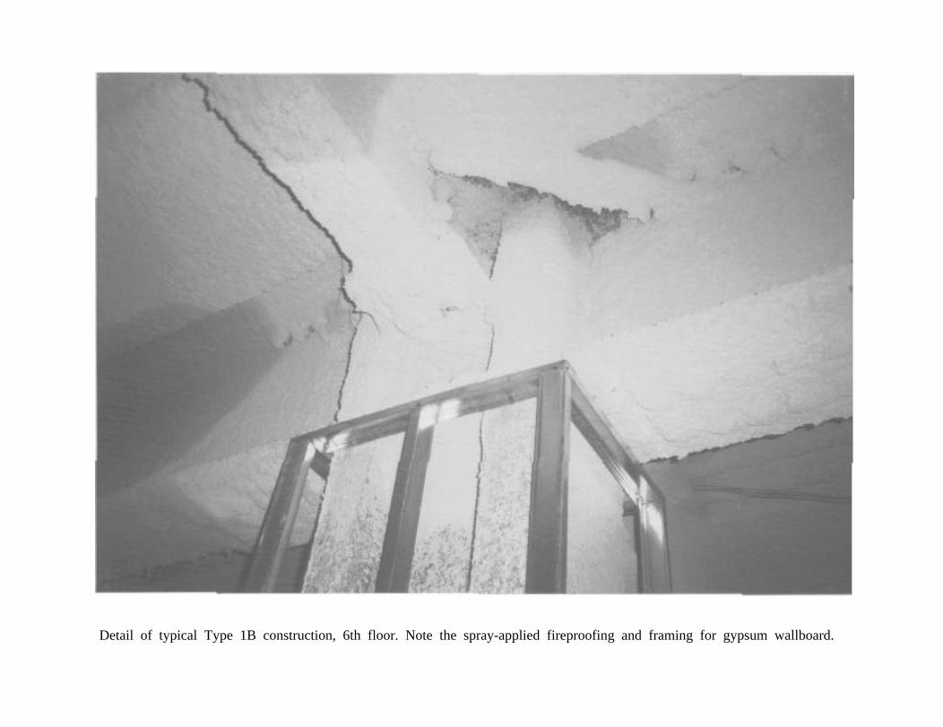
Detail of typical Type 1B construction, 6th floor. Note the spray-applied fireproofing and framing for gypsum wallboard.
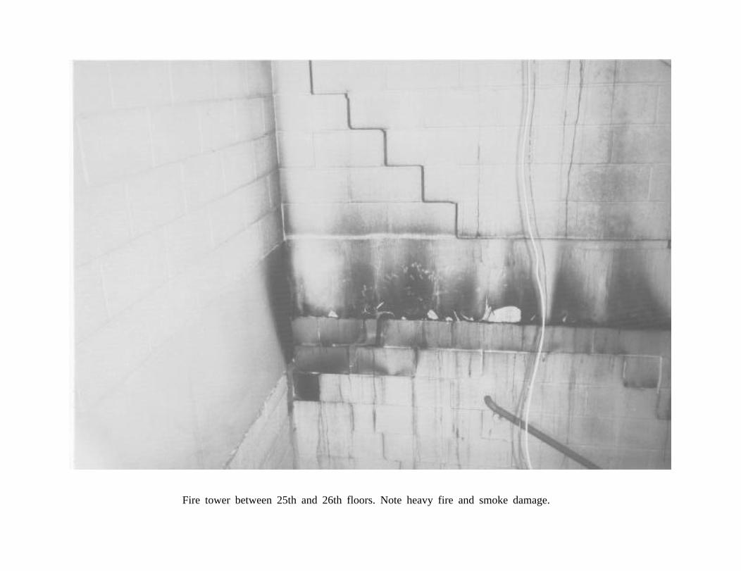
Fire tower between 25th and 26th floors. Note heavy fire and smoke damage.
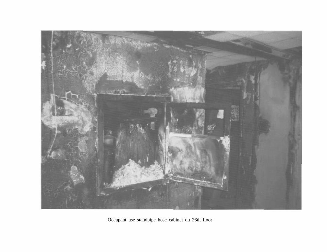
Occupant use standpipe hose cabinet on 26th floor.
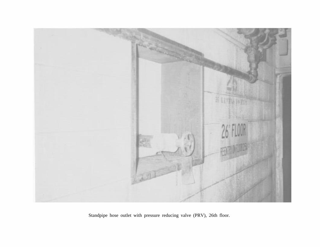
Standpipe hose outlet with pressure reducing valve (PRV), 26th floor.
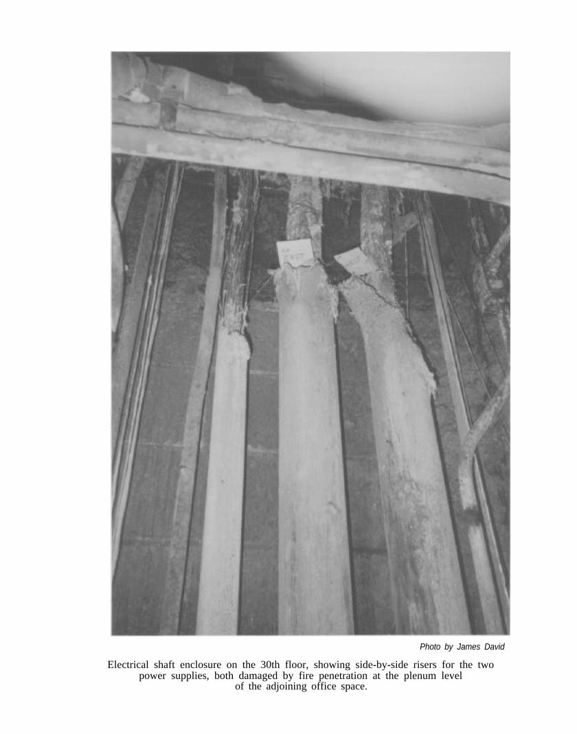
Photo by James David
Electrical shaft enclosure on the 30th floor, showing side-by-side risers for the twopower supplies, both damaged by fire penetration at the plenum level
of the adjoining office space.
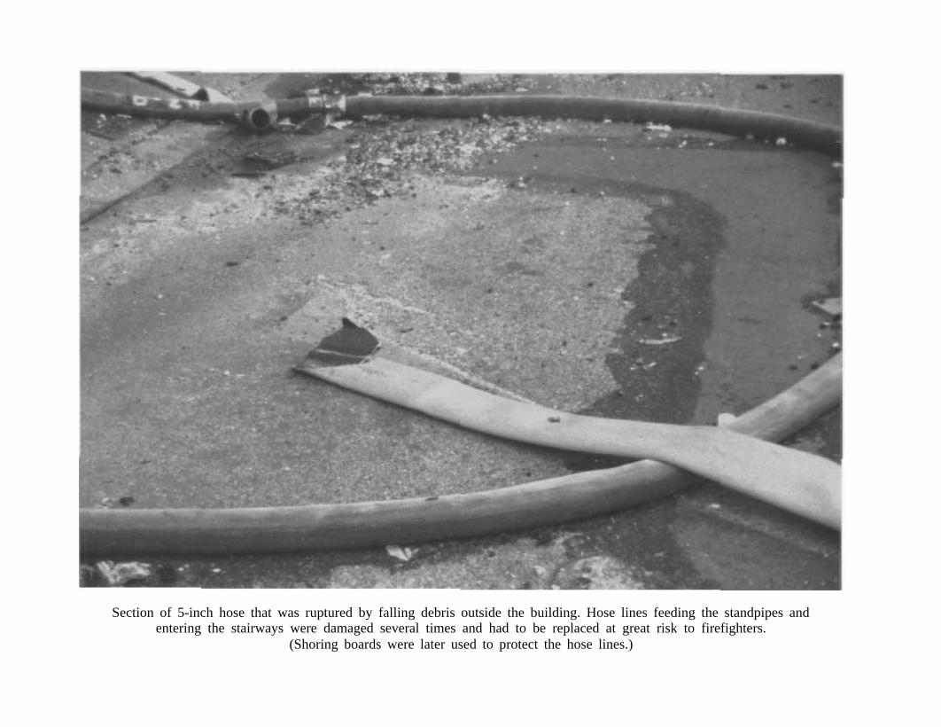
Section of 5-inch hose that was ruptured by falling debris outside the building. Hose lines feeding the standpipes andentering the stairways were damaged several times and had to be replaced at great risk to firefighters.
(Shoring boards were later used to protect the hose lines.)
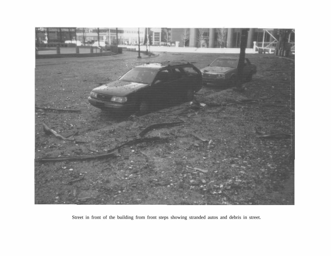
Street in front of the building from front steps showing stranded autos and debris in street.
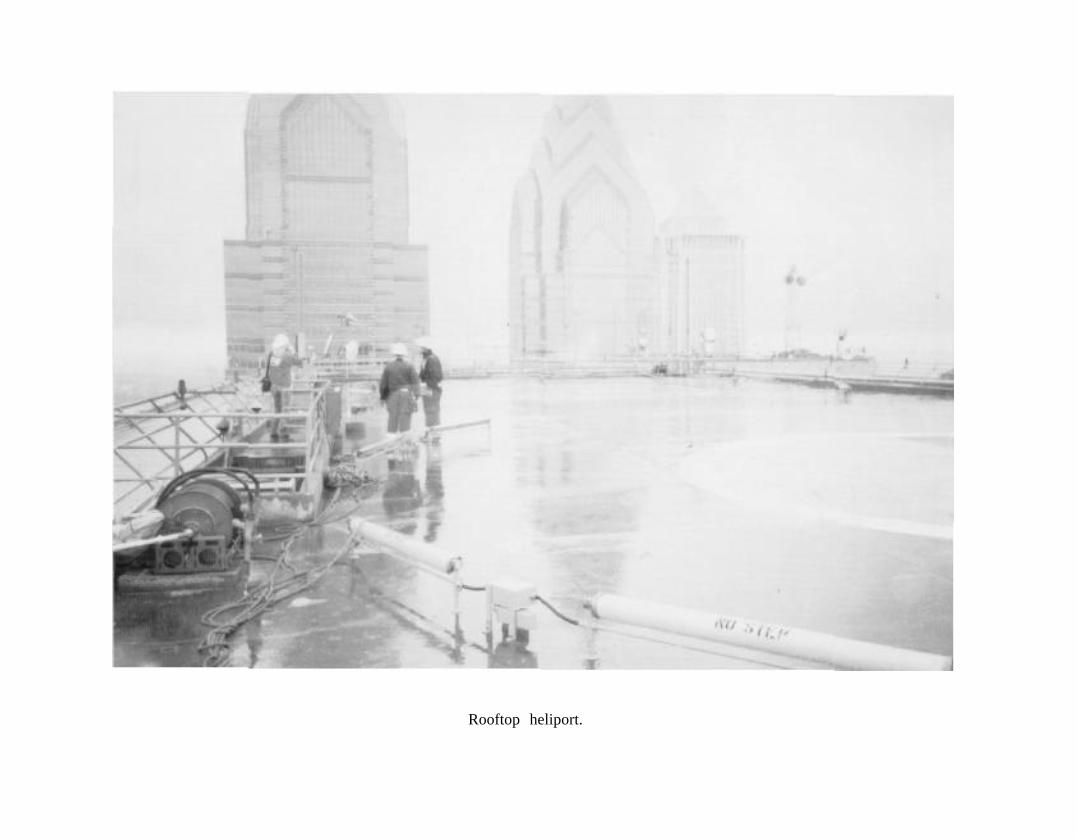
Rooftop heliport.